overview of spanning tree protocol
TRANSCRIPT

Spanning Tree ProtocolOverview
PRESENTED BY
ARASH FOROUGHI
Iran, November 2015

Slide 2
1. Introduction and Purpose of STP
2. STP Standards Overview
3. IEEE 802.1D STP Protocol
4. IEEE 802.1w RSTP Rapid STP
5. IEEE 802.1Q CST Common Spanning Tree
6. Cisco PVST+ and PVRST+
7. IEEE 802.1s MST Multiple Spanning Tree Protocol
Contents
Slide 3
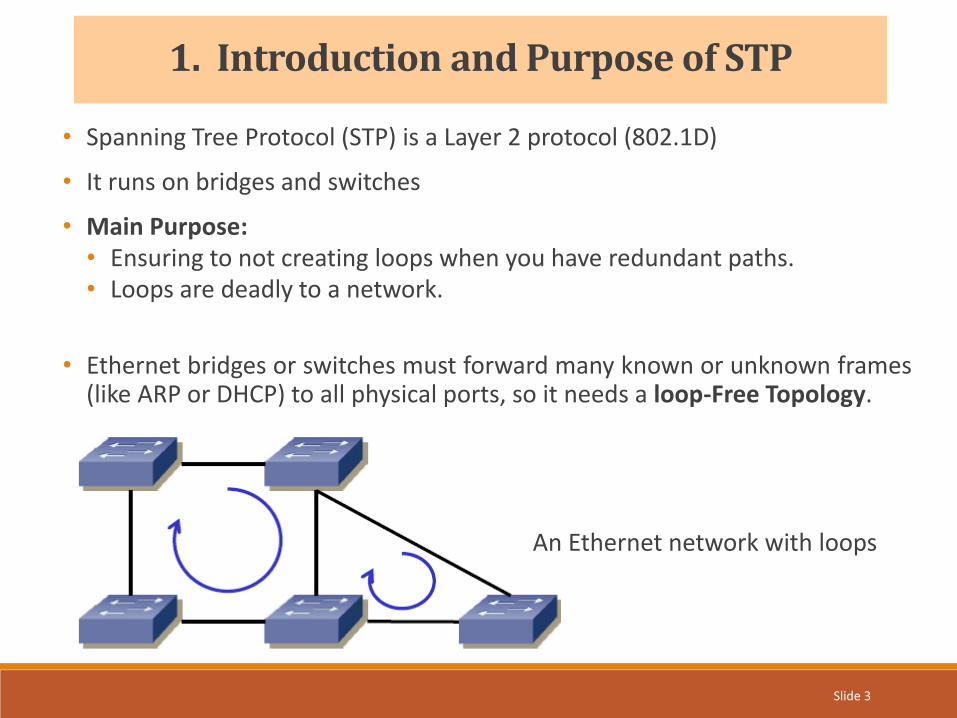
• Spanning Tree Protocol (STP) is a Layer 2 protocol (802.1D)
• It runs on bridges and switches
• Main Purpose:• Ensuring to not creating loops when you have redundant paths.• Loops are deadly to a network.
• Ethernet bridges or switches must forward many known or unknown frames(like ARP or DHCP) to all physical ports, so it needs a loop-Free Topology.
1. Introduction and Purpose of STP
An Ethernet network with loops

Slide 4
2. STP Standards Overview
Standard Description Abbreviation
IEEE 802.1D• Loop Prevention• Auto-reconfig of tree in case of any changes• Slow convergence (up to 50 Mbps)
STP
IEEE 802.1w• Rapid Spanning Tree Protocol
• Improved STP with faster convergence• Backward compatible with STP
RSTP
IEEE 802.1Q• Virtual LAN
• Defining 1 common spanning tree (CST) for all VLANs CST
Cisco Proprietary
• Per VLAN Spanning Tree• 1STP instance per VLAN• PVST+ is an improved variant of PVST
PVSTPVST+
Cisco Proprietary
• Per VLAN Rapid Spanning Tree• 1RSTP instance per VLAN
PVRST+ orR-PVST+
IEEE 802.1s• Multiple (Instance) Spanning Tree protocol• Multiple instance of VLAN mapped to 1 STP (both CST and PVST)
MSTP orMISTP
Slide 5
STP Overview
• Providing path redundancy while preventing undesirable loops in network.
• In a layer 2 network, only one active path can exist between any 2 stations.
• STP calculates and selects the best loop-free path.
• Layer 2 LAN ports send and receive STP frames and network devices use theframes to construct a loop-free path.
• If a loop exists in network, end stations receive duplicate messages andnetwork devices learn end station MAC addresses.
• STP defines a tree with a Root Bridge and a loop-free path from the root toall devices.
• STP forces redundant data paths into a blocked state.
3. STP Protocol – IEEE 802.1D
Slide 6
• Bridge:
• A bridge connects two or more LAN segments.
• Today’s networks are predominantly Switch based. For STP switch = bridge.
• Root Bridge (RB):
• It’s the bridge (or switch) that provides an interconnection point for all segments.
• Every bridge in a LAN has a path to the root.
• STP can select the root bridge automatically but if administrator wants, he canchange the RB according to the network.
• Non-Root Bridge (NRB):
• Any bridge that is not the RB is called Non-root Bridge.
3. STP Protocol – IEEE 802.1D
Slide 7
• Root Port (RP):
• The port that leads towards the RB. (or the port has the lowest path cost to RB).
• Every NRB has exactly 1 RP.
• The Root Bridge (RB) doesn’t have any Root Port (RP).
• Designated Port (DP):
• Every LAN segment has 1 DP. Every bridge receives the frames from DP andforward them through its RP towards the Root Bridge.
• DP guarantees that every segment is connected to the STP tree topology.
• In Root Bridge (RB) = All ports are Designated Port (DP)
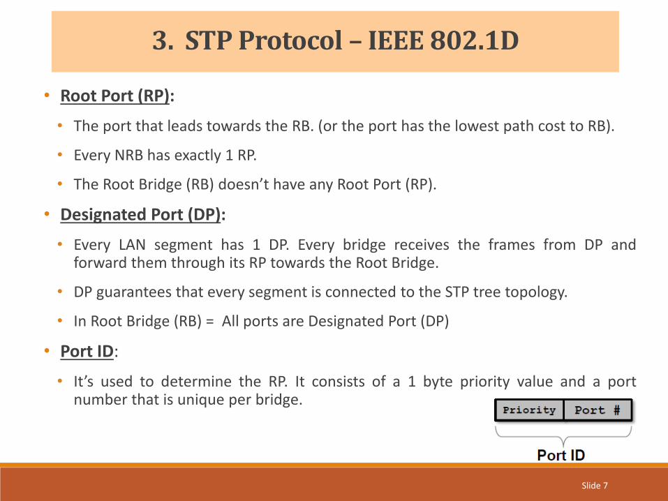
• Port ID:
• It’s used to determine the RP. It consists of a 1 byte priority value and a portnumber that is unique per bridge.
3. STP Protocol – IEEE 802.1D

Slide 8
Bridge Protocol Data Units (BPDU)
• Each network device send BPDUs to exchange topology information.
• There is 2 types of BPDU:
1. Configuration BPDU• The unique bridge ID of the root device in the network• The STP path cost to the root• The bridge ID of the transmitting bridge• The identifier of the transmitting port• Values for the hello, forward delay, and max-age protocol timers
2. Topology Change Notification (TCN) BPDU• One network device is elected as the root bridge.• The shortest distance to the root bridge is calculated for each network device based on
the path cost.• A designated bridge for each LAN segment is selected. This is the network device closest
to the root bridge through which frames are forwarded to the root.• A root port is selected. This is the port providing the best path from the bridge to the root
bridge.• Ports included in the spanning tree are selected.
3. STP Protocol – IEEE 802.1D

Slide 9
Election of the Root Bridge
• STP uses a 64-bit bridge ID consisting of a bridge priority value and MAC address forselection of the Root Bridge.
• STP also uses one MAC address per VLAN to make the bridge ID unique for eachVLAN.
• The bridge with the lowest BID in the network is elected as root bridge.• If 2 BIDs have the same priority value, the bridge with the lower MAC address wins.
1. First, all bridges send configuration BPDUs with their own BID.
2. All bridges compare the received BPDUs with their own BID. If it’s lower, they stopsending own BPDUs but they start forwarding received BPDUs to all interfaces.
3. STP Protocol – IEEE 802.1D

Slide 10
3. STP Protocol – IEEE 802.1D
• The Root Bridge should be a powerful device and be positioned at the center of thenetwork.
• In the below example, Br0 is elected as RB because it has the lowest BID, but theadministrator changed the root bridge to BR2, because it has the fast link with1Gbps.

Slide 11
3. STP Protocol – IEEE 802.1D
STP Port State Overview
State Description Process BPDUs Learn MAC
InitInitialization of an port (bootstrap).Actually not an STP port state.
No No
DisabledAdministrative state.The port doesn’t participate in STP operations.
No Mo
BlockingThe port doesn’t forward Ethernet frames and doesn’t learn MAC addresses. (Backup State)
Yes (receive and process BPDUs
only)No
ListeningComputation of loop-free topology is carried out in this state and the port is assigned its role. (RP, DP, NDP)
Yes (Send and receive BPDUs)
No
LearningAdditional state to delay forwarding of Ethernet frames to avoid flooding the network.
YesYes (Populate MAC address
table)
ForwardingNormal operation of forwarding Ethernet frames (user traffic)
Yes Yes

Slide 12
3. STP Protocol – IEEE 802.1D
• Port states and transitions for STP are defined by the following diagram:

Slide 13
3. STP Protocol – IEEE 802.1D
• In reality, the ports are in different states (Blocking, Listening, Learning) untilreaching a stable state (Forwarding or Blocking).

Slide 14
4. RSTP Rapid STP - IEEE 802.1w
Differences between STP & RSTP
1. The main difference is that RSTP places 3 ports states Listening, Blocking andDisabled all into a new state called Discarding state. Learning and forwarding portsremain more or less the same.
2. In STP, bridges only send out a BPDU when they received one on their RP from RB.In RSTP, enabled switches send out BPDUs in every hello time.
3. STP includes two port types: Root Port and Designated Port.RSTP includes two additional port types: Alternate Ports and Backup Ports.
• Alternate Port is a port that has an alternative path or paths to the RB, but is currently in a Discarding State.
• Backup Port is a port that could be used to reach RB, but there is already an active STP Designated Port for that segment. (can be considered as an additional unused designated port).
Slide 15
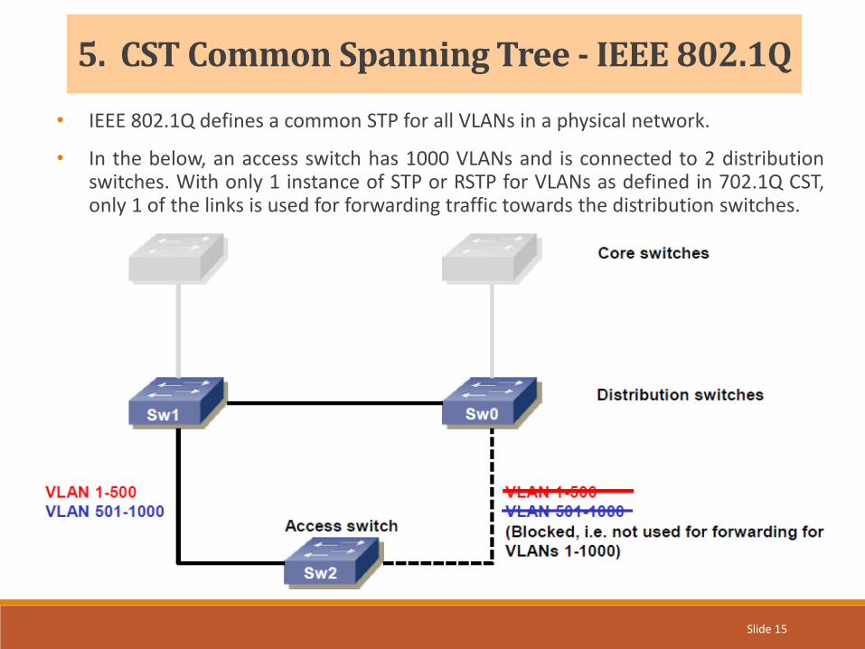
5. CST Common Spanning Tree - IEEE 802.1Q
• IEEE 802.1Q defines a common STP for all VLANs in a physical network.
• In the below, an access switch has 1000 VLANs and is connected to 2 distributionswitches. With only 1 instance of STP or RSTP for VLANs as defined in 702.1Q CST,only 1 of the links is used for forwarding traffic towards the distribution switches.
Slide 16
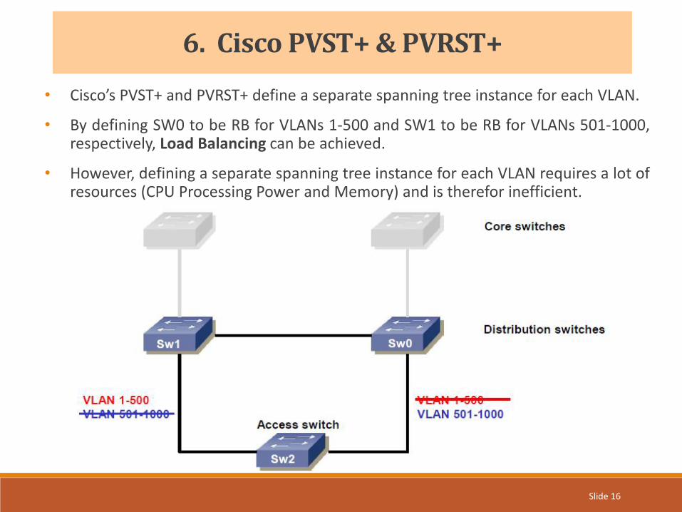
6. Cisco PVST+ & PVRST+
• Cisco’s PVST+ and PVRST+ define a separate spanning tree instance for each VLAN.
• By defining SW0 to be RB for VLANs 1-500 and SW1 to be RB for VLANs 501-1000,respectively, Load Balancing can be achieved.
• However, defining a separate spanning tree instance for each VLAN requires a lot ofresources (CPU Processing Power and Memory) and is therefor inefficient.

Slide 17
7. MST Multiple STP - IEEE 802.1s
• MSTP, originally defined in 802.1s and then merged to 802.1Q-2005, allowsmapping multiple VLANs to a single spanning tree instance.
• This reduces the resource requirements while preserving the advantages of havingmultiple spanning trees for load balancing purposes.
• In the example below, the VLANs are mapped to 2 separate spanning tree instancesas follows:• VLANs 1-500 : Spanning tree instance 1• VLANs 501-1000 : Spanning tree instance 2

Slide 18
1. http://www.cisco.com/c/en/us/td/docs/switches/lan/catalyst6500/ios/15-0SY/configuration/guide/15_0_sy_swcg/spanning_tree.html#wp1038835
2. http://www.cisco.com/c/en/us/support/docs/lan-switching/spanning-tree-protocol/5234-5.html
3. http://www.netwaxlab.com
4. http://www.indigoo.com
References

Thank youArash Foroughi
Iran, November 2015