overview and prospects for development of wave and
TRANSCRIPT

Brodogradnja/Shipbuilding Volume 65 Number 2, 2014
Carlos GUEDES SOARES Joydip BHATTACHARJEE Debabrata KARMAKAR
ISSN 0007-215X eISSN 1845-5859
OVERVIEW AND PROSPECTS FOR DEVELOPMENT OF WAVE AND OFFSHORE WIND ENERGY
UDC 629.563. Review paper
Summary
An overview of the present state of development of offshore renewable wave and wind energy is presented and future prospects are discussed. The information on some of the current wave energy systems worldwide are given as indicative of the present state of affairs. The main working principles of wave energy systems are described and the differences in terms of working principle, conversion chain, location and power take-off systems are highlighted. Some of the technology challenges are identified and the prospects of utilization of the various wave energy concepts are discussed comparing the characteristics of the devices in particular their power output. The evolution of the concepts of wind turbines with time and the main types of offshore wind turbine concepts are presented, from the shallow water fixed ones to the floating ones. The development of various numerical codes for the dynamic analysis of offshore wind turbines and the studies carried out based on the codes for hydrodynamic, aerodynamic, structural and response due to control system are presented. The present status of wind energy compared to wave energy and the role of naval architects and ocean engineers for the design and analysis of wave energy device and offshore wind turbine technology are presented and discussed.
Keywords: Offshore renewable energy; Wave power; Wave energy converters; Offshore wind turbine; Coupled dynamic analysis.
1. Introduction
Energy is the ability to do work and thus is absolutely essential for existence of human civilization. After the industrial revolution in the eighteenth century, the demand of energy has increased in manifolds. In today’s life, energy is essential in every aspect, be it agriculture, transportation and information technology. The primary resource of energy is still the fossil fuel, i.e. coal, petroleum and the natural gas. However, the fear of exhaustion of the fossil fuel in the future combined with the concern for national energy security as the concentration of fossil fuel is restricted to certain regions has forced to look for renewable energy resources. The renewable energy is derived from natural processes that are replenished constantly such as the wind, waves, sun, geothermal, hydrogen, biomass etc. and are considered to be green. In the recent decades, the interest in the use of renewable energy has

C. Guedes Soares, J. Bhattacharjee, D. Karmakar Overview and prospects for development of wave and offshore wind energy
88
gained significant attention due to the rising concern over global warming and environmental pollution.
Among the renewable energy resources, the wind energy represents the mainstream energy source of new power generation and an important player in the world's energy market. The wind energy is observed to be the one of the suitable solutions for global climate change and energy crisis which can be regarded as promising renewable, clean, and reliable energy source. On the other hand, the world oceans contain such a huge amount of energy that if exploited efficiently, can end the global energy problem. Therefore, it is relevant to discuss different aspects of the two important branches of renewable energy resources, namely the wave and the wind energy and understand the present status and the future prospects.
2. Wave power
Wave power is renewable energy derived from ocean waves. It is different from tidal energy, which is derived from underwater equipment that captures the ongoing movement of ocean currents powered by gravity and the Earth’s rotation. Ocean waves are generated due to wind blowing over the ocean surface. The pressure difference caused by Sun’s heating leads to wind blowing and hence ocean waves are a result. Amongst the other marine renewable energy resources, wind driven surface waves contain a great amount of energy. The wave energy level is usually expressed as power per unit length. Typical values for good offshore locations range between 20 kW/m - 70 kW/m and occur mostly in moderate to high latitudes as can be seen in Fig. 1.
Fig. 1 Global average wave energy distribution (Pelamis wave power)
A wide spread effort is seen presently to use advanced numerical methods to assess the wave energy resources along various coasts, such as the Baltic Sea (Bernhoff et al. (2006)), Continental Portugal (Rusu and Guedes Soares (1999)), the Spanish coast (Iglesias and Carballo (2009, 2010)), USA (Defne et al. (2009)), Canada (Dunnett and Wallace (2009)), Sweden (Waters et al. (2009)), the French coast (Gonçalves et al. (2014)) among others. These studies typically use numerical methods to study the generation of storms far away and the corresponding propagation of swell, as well as the waves induced by local winds. Some studies deal with the specific aspects of estimating wave resources around islands, which are specially interesting type of applications (Stopa et al. (2009), Iglesias and Carballo (2010), (2011), Rusu and Guedes Soares (2012a, b) and Gonçalves et al. (2013)).
Overview and prospects for development of wave and C. Guedes Soares, J. Bhattacharjee, D. Karmakar offshore wind energy
89
The best wave energy environments are along western coastlines because the largest, most consistent winds come from the west. Seasonal variations are larger in northern than southern hemisphere and hence, southern coasts of South America, Africa and Australia are particularly attractive for wave energy exploitation as evident from Fig 1. Globally, wave energy leaders are the UK, Portugal, Australia and New Zealand. Northern Canada and southern Africa are other wave power hotspots. In the United States, wave power hotspots are California, Oregon, Washington and Alaska. Portugal is home to the world’s first commercial wave farm, Aguçadoura Wave Farm near Póvoa de Varzim, north of Porto. Three Pelamis machines were initially installed with 2.25MW production capacity in Aguçadoura Wave Farm. The project was suspended for a period due to financial and technical difficulties. It is once again revived with a follow up project at Aguçadoura to install, in phases, a farm of up to 26 machines with an installed capacity of 20MW.
2.1 Historical evolution of wave energy conversion devices
The first evidence of the concept of wave energy extraction was found more than 200 years back when father son duo of Girard from France filed the first patent in 1799 (Ross (1995)). Since then, more than one thousand patents were taken on different concepts to harness energy from ocean waves (McCormick (1981)). However, the modern research started in the 1940’s in Japan. In this respect, Yoshio Masuda (1925 - 2009), a navy officer from Japan, may be regarded as the father of wave energy technologies, who invented the floating Oscillating Water Column (OWC) technology to extract energy from waves. He developed a navigation buoy with an air turbine that was later commercialized in Japan and USA in the 1960’s (Masuda (1971)). He later supervised the construction of a large floating barge named Kaimai, containing multiple OWC chambers having different types of air turbines. Another pioneer in the field of wave energy extraction was Michael E. McCormick from US Naval Academy, who developed the self-rectifying air turbines for OWC devices in the 1970’s.
Despite scattered personal interests, the industrial and academic progress in this field was still at its infant stage until the oil crisis in the 1970’s. The acute oil crisis combined with the concern for national security forced the nations to look for renewable energy resources. In 1974, Stephen Salter from University of Edinburg published a paper in the prestigious journal Nature on the concept of a nodding floater, called The Duck, which drew significant attention from the scientific community. The UK and the Norwegian governments started funding several wave energy research and development programs. Although the governmental interests died down once the oil crisis was over in the 1980’s, the theoretical developments were in progress with significant contributions from different branches of science and engineering, especially from applied mathematicians.
However, the scenario in Europe changed in the 1990’s when the European Commission made the decision to include wave energy in their R & D program on renewable energy. Several projects were funded to investigate different concepts and their feasibility of commercial implementation. The Ocean Energy Systems Implementing Agreement (OES) was launched in 2001 under the flagship of International Energy Agency (IEA) to speed up the wave energy developments thorough international collaborations and exchange of knowledgebase. Presently, the number of contacting parties in OES is nineteen and membership of the OES is earned by invitation of the Executive Committee to country governments. In the last two decades, several conferences, workshops and meetings were held to exchange ideas and information. Therefore, a significant progress has been made in the theoretical analysis of wave energy conversion devices. However, the utilization of wave energy in the commercial stage is yet to be achieved on a business scale due to various

C. Guedes Soares, J. Bhattacharjee, D. Karmakar Overview and prospects for development of wave and offshore wind energy
90
technical and financial challenges. Detailed reviews on historical progress, different concepts and technological developments can be found in Thorpe (1999), Clément et al. (2002), Harris et al. (2004), Falnes (2007), Drew et al. (2009), Falcão (2010) and Guedes Soares et al. (2012). The detailed discussion on the theoretical developments on ocean wave and oscillating wave energy systems, the difficulties and the future prospective can be found in Falnes (2004) and Cruz (2008).
2.2 Classification approaches of wave energy converters
There exists a large variety of concepts to extract energy from ocean waves all over the world. More than one thousand patents have been registered for different wave energy conversion devices only in Japan, Europe and North America (Clément et al. (2002)). Therefore, there is no unique classification approach to categorize the existing concepts and designs. In order to classify the devices, it is important to understand the basic characteristics and requirements of the wave energy converters (WECs).
Most of the wave energy comes from the rising and falling of the water free surface and hence requires the device to be exposed to the incoming waves. Therefore, the placement of the device is important and it can be installed at the shoreline, near to the shore or offshore. The distinction between near-shore and offshore is often related to design requirements for water depth, which generally increases with distance from the shore, the energy content of waves, which is being greater offshore, and access for deployment, retrieval, operation and maintenance. The near-shore and offshore devices may be either bottom-mounted or floating. In general, near-shore devices are being fixed to the seabed by a static member and the offshore devices are being moored through cables to hold on station.
Wave energy is in general extracted through the reaction forces between two or more bodies and this is one of the biggest design challenges. To build such a system, two or more bodies need to move relative to each other, while at least one body interacts with the waves. One of the numerous approaches is to allow one body to move freely with the waves, while another is held static as in the case of a floating buoy reacting against the seabed. Alternatively, all of the bodies may be dynamic and energy is extracted from their relative motion. Each moving body may be labelled as either a displacer or a reactor. Displacer is the body that is moved by the waves such as buoyant vessel, or, as in the case of Oscillating Water Column (OWC) devices, a mass of water. If buoyant, the displacer may pierce the surface of the waves or be submerged. On the other hand, reactor is the body that provides reaction to the displacer. It could be a body fixed to the seabed, or the seabed itself or another structure or mass that is not fixed, but moves in such a way that reaction forces are created. A degree of control over the forces acting on each body and acting between the bodies is often required to optimize the amount of energy captured. In some designs, the reactor is actually inside the displacer, while in others it is an external body. Internal reactors are not subject to wave forces, but external ones may experience loads that cause them to move in ways similar to a displacer. Thus, some devices do not have dedicated reactors at all, but rather a system of displacers whose relative motion creates a reaction system.
There are different approaches that have been proposed in the literature to classify WECs (Falcão (2010)). However, the common practice is to classify the devices based on the basic technology. Presently, based on the working principles, there are three major types of WECs – the oscillating water column device, the overtopping devices and the oscillating bodies.
Overview and prospects for development of wave and C. Guedes Soares, J. Bhattacharjee, D. Karmakar offshore wind energy
91
2.2.1 Oscillating water column device
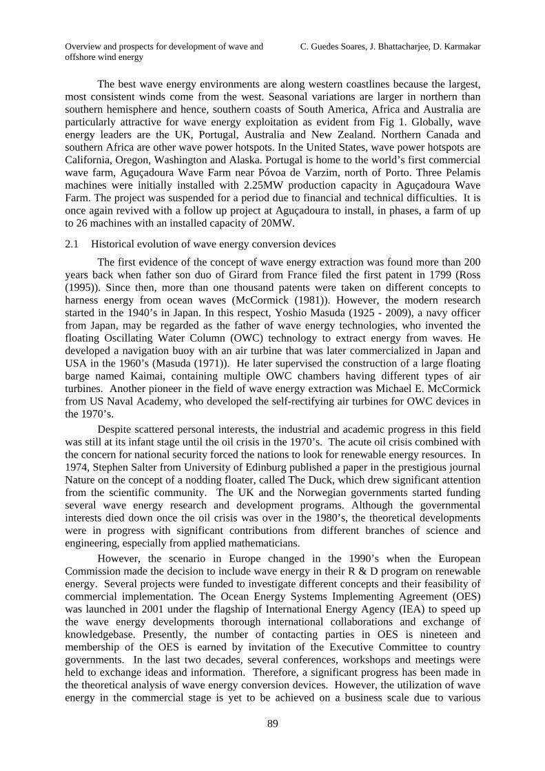
The oscillating water column (OWC) comprises of a partly submerged structure called ‘collector’ which is open to the sea below the water surface as shown in Fig 2. A column of air is trapped above the internal free surface of the water column. As waves enter and exit the collector, the water column moves up and down and acts like a piston on the air. The compressed air is channeled towards a turbine and forces it to turn. The turbine is in general a self-rectifying one to avoid the modification of the airflow and is coupled to a generator to produce electricity. A low pressure Wells turbine is commonly used in the PTO system. The OWC concept is known to the first to harness wave energy and hence called as the first generation of devices. A variety of OWC devices have been proposed and are being studied due to its simplicity in design and robustness (Duckers (2004)).
The oscillating water column (OWC) devices can be either fixed or floating. In general, fixed OWCs are installed on shore or near shore. As there is no moving parts or electrical equipment in contact with the sea water and no underwater cable is required, these are considered to be easy for installation and maintenance. The disadvantage is that the wave loses energy as it progresses towards the shoreline and hence the near shore wave climate is less energetic. However, proper positioning of the device and the favorable bathymetry may compensate the lost energy through refraction and diffraction. Several fixed OWC prototypes have been in operation in shore areas as in Toftestallen, Bergan, Norway (1985), Sakata, Japan (1990), Vizhinjan, Kerala, India (1990), Pico, Azores, Portugal (1999), LIMPET plant, Islay Island, Scotland (2000), Port Kembla, Australia, (2005) (see Alcorn et al. (2005)), Mutriku, Spain (2008) (see Torre-Enciso (2009)).
Fig. 2 Schematic diagram for OWC device
Floating OWC devices are in general designed for deep water regions as in the case of the first OWC built in Japan under the supervision of Yoshio Masuda. The larger barge type multiple OWC device “Kaimai” made in Japan was also a floating offshore device. Masuda further modified the geometry of the OWC to introduce the backward bent duct buoy (BBDB) and the concept was studied in different countries (Masuda et al. (1995), Hong et al. (2004)). Efforts are underway in Ireland to construct a larger version of BBDB and models are tested in the sheltered Galway Bay, western Ireland. The Mighty Whale (Hotta et al. (1996)) is another floating OWC which was developed in Japan and a prototype of around 50m length has been tested for several years, with three chambers connected to Wells turbines that drive electric generators. Several studies have also been made for SPAR type OWC (McCormick (1976), Korde (2000)). These are a relatively long vertical tubes opened at both ends, which have a heave motion. The pressure of the inner OWC with respect to the floater pressurizes the air chamber that is connected to a turbine (Lye et al. 2009).
C. Guedes Soares, J. Bhattacharjee, D. Karmakar Overview and prospects for development of wave and offshore wind energy
92
2.2.2 Overtopping devices
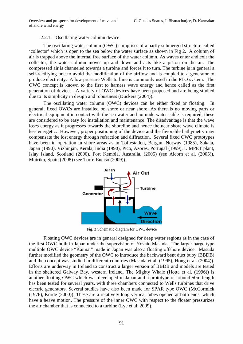
Overtopping devices are in general large structures, shore-based or in the ocean that channel waves into a basin or reservoir as shown in Fig 3. When the basin’s water level becomes higher than the ocean’s, the head of collected water turns the turbines as it flows back out to sea and the turbines are coupled to generators to produce electricity. The technology is similar to a hydropower system, in which draining water runs a turbine. These machines make use mainly of well-established technologies, thus reducing development costs and risks; the only moving parts are the turbine(s) and there are no components moving with the waves, thus minimizing loadings and breaking risks, as well as reducing the requirements on the structure and moorings. They are easily scalable without the need for reconfiguration or tuning. The presence of a reservoir, acting as a buffer, helps smoothing the power output. Examples of overtopping devices are the Tapchan (Tapered Channel Wave Power Device), Norway in 1985, Wave Dragon, Denmark in 2003 (Kofoed et al. (2006) and Seawave Slot-Cone Generator (SSG) (Margheritini et al. (2009)). The hydrodynamics of overtopping devices is highly nonlinear and hence the linear wave theory is not adequate for analysis of the aforementioned devices.
(a) (b)
Fig. 3 Schematic diagram for (a) shore based and (b) floating overtopping device
2.2.3 Oscillating body
Oscillating body devices are commonly meant for offshore regions to exploit the highly energetic wave climate which in general kept at water depth more than 50m. They are either submerged or floating on the surface and their relative motion with respect to the sea bottom or another body is used to drive an electric generator. The analysis becomes more complex due to the presence of mooring systems, under water cables, extreme sea states, difficulties in installation and maintenance and they are often termed as the third generation of devices. Oscillating bodies can be further categorized as point absorbers, terminators and attenuators.
(a) Point absorber: Point absorbers are floating or submerged structure that absorbs energy from all directions by virtue of its movements at or near the water surface as shown in Fig 4. Their horizontal dimension is very small compared to the incident wave length and hence the presence of these devices does not alter the incident wave characteristics. It may be designed so as to resonate with larger amplitudes than the waves themselves. This feature is useful to maximize the amount of power absorption. The power take-off system may take a number of forms, depending on the configuration of displacers/reactors.
Single body point absorbers are generally designed as a heaving buoy reacting against the sea bed or another structure fixed to the sea bed. Early evidence of single body point absorber device is found in Japan and Norway in the 1980’s (Falcão (2010)). The concept of taut moored buoy point absorber is being developed at Uppsala University in Sweden (Waters et al. (2007)). Vantorre et al. (2004) have proposed a heaving point absorber that moves with respect to a platform.

Overview and prospects for development of wave and C. Guedes Soares, J. Bhattacharjee, D. Karmakar offshore wind energy
93
Point absorbers that are connected to the sea bottom are not the most frequent ones but reference can be made to one taut-moored buoy concept that use a linear electric generator on the bottom (Eriksson et al. (2005), Leijon et al. (2006)). Elwood et al. (2010) at Oregon State University, USA have also developed a wave energy conversion system that consists of a deep draft spar and a taurus-shaped buoy having a saucer-shaped profile. The outer buoy is free to heave relative to the spar but is constrained in all other degrees of freedom by a linear bearing system. The systems that depend on the relative motion of two bodies (Falnes (1999)) are more frequent. Examples are the IPS buoy (Gomes et al. (2010)) Aquabuoy (Weinstein et al. (2004)), the Wavebob (Weber et al. (2009)), PowerBuoy (Ocean Power Technologies, USA) which are floating buoys that have parts moving vertically.
Fig. 4 Schematic diagram of floating and submerged point absorbers (US Dept. of Energy)
The Archimedes Wave Swing (AWS) is fully submerged heaving oscillating device. It has a bottom fixed cylinder and oscillating one on the upper part, which responds to the pressures of the waves as they pass. The system was tested in Portugal in 2004 and its performance can be improved with control strategies (Valério et al. (2007)). There are oscillating bodies that extracts the energy of ocean waves through the pitching motion. The most well-known example of pitching WEC is the Duck invented by Stephen Salter from University of Edinburg, UK in 1970’s (Salter (1974)). Another device that depends on its pitch motion is the PS Frog Mk.5, which is a floater that has a vertical floater with a ballast tank hanging below (McCabe et al. (2005)). When it pitches there is a mass that moves sideways above the sea level, providing the motion for the PTO. The Searev WEC developed at Ecole Centrale de Nantes, France is also a floating pitching device that fully encloses a horizontal axis wheel. The wheel acts as a pendulum and the rotational motion of the wheel with respect to the hull is used to run a hydraulic PTO.
(b) Terminator: The terminator devices are also floating structures that move at or near the water surface, but it absorbs energy in only a single direction. The device extends in the direction normal to the predominant wave direction so that the incoming waves are restrained. Again, resonance may be employed and the power take-off system may take a variety of forms. An example of this type is the famous Salter Duck, which has undergone different design improvements with time (Salter (1993)).
C. Guedes Soares, J. Bhattacharjee, D. Karmakar Overview and prospects for development of wave and offshore wind energy
94
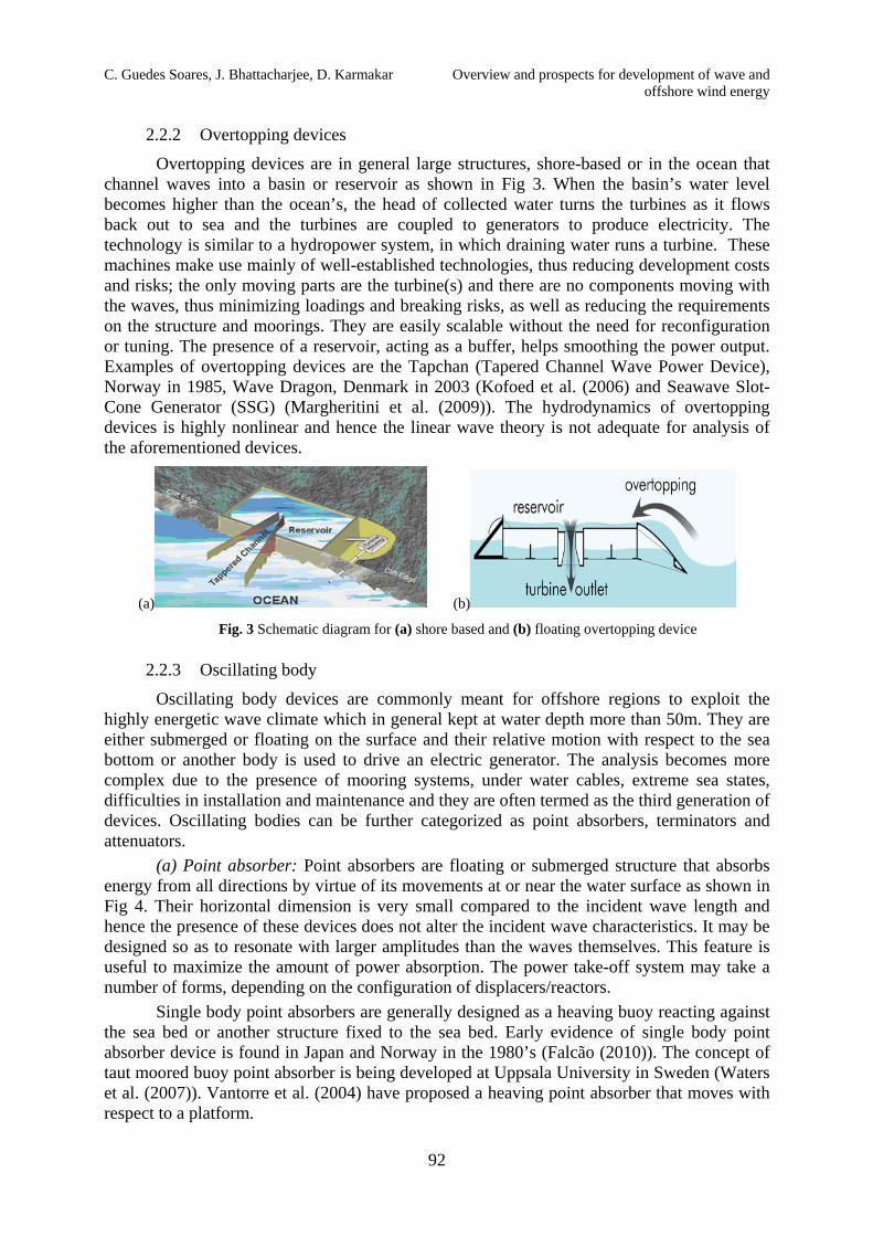
Fig. 5 Wave Star wave energy converter (courtesy WAVESTAR)
Other type of structures has one main platform where one PTO is installed and then several small floating point absorbers are deployed and their motion will react with the platform. One example is the FO3, which is based on a square floating structure with a hydraulic PTO around which there is an array of 21 axisymmetric buoys (Lendenmann et al. (2007)). The Wave Star is made of two rectilinear arrays of floaters located on both sides of a bottom mounted steel structure aligned with the dominant wave direction (see Fig 5). The swings of the buoys pump oil into the hydraulic system. A prototype with 24m long has been tested for some years connected to the grid (Marquis et al. (2010)). A similar system for wave energy absorption was adopted by Estefen et al. (2008), although in this case it is fixed to a vertical breakwater.
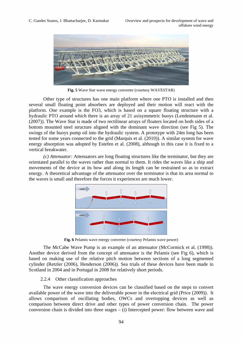
(c) Attenuator: Attenuators are long floating structures like the terminator, but they are orientated parallel to the waves rather than normal to them. It rides the waves like a ship and movements of the device at its bow and along its length can be restrained so as to extract energy. A theoretical advantage of the attenuator over the terminator is that its area normal to the waves is small and therefore the forces it experiences are much lower.
Fig. 6 Pelamis wave energy converter (courtesy Pelamis wave power)
The McCabe Wave Pump is an example of an attenuator (McCormick et al. (1998)). Another device derived from the concept of attenuator is the Pelamis (see Fig 6), which is based on making use of the relative pitch motion between sections of a long segmented cylinder (Retzler (2006), Henderson (2006)). Sea trials of these devices have been made in Scotland in 2004 and in Portugal in 2008 for relatively short periods.
2.2.4 Other classification approaches
The wave energy conversion devices can be classified based on the steps to convert available power of the wave into the deliverable power in the electrical grid (Price (2009)). It allows comparison of oscillating bodies, OWCs and overtopping devices as well as comparison between direct drive and other types of power conversion chain. The power conversion chain is divided into three stages – (i) Intercepted power: flow between wave and

Overview and prospects for development of wave and C. Guedes Soares, J. Bhattacharjee, D. Karmakar offshore wind energy
95
primary interface, (ii) Captured power: flow between primary interface and PTO and (iii) Delivered power: flow between PTO and final conversion stage. The wave energy is the combination of potential and kinetic energy. The overtopping devices fall in the category that harness the potential energy contained in the waves. The oscillating water column (OWC) device uses the pressure or kinetic energy to run the turbines. On the other hand, mechanical energy of the wave is exploited by the oscillating bodies like point absorbers, terminators and attenuators.
Amongst other approaches, WEC devices can be further classified in terms of the power take off (PTO) systems. A variety of PTO arrangements have been proposed, which are not device specific, but in general can be associated to a number of devices. The PTO elements can be categorized depending on the working fluid (if any) like high pressure oil, low pressure water, positioning of the PTO (with respect to machine, shore and surface), components, control strategies and efficiency. Some PTO systems are offered as off-the-shelf package to device developers. A more extensive description of the PTO systems for the WECs can be found in Mynett, et al. (1979) and Salter et al. (2002). The details of various types of WECs are provided in Table 1.
Table 1: Classification of WECs
Wave Energy Concepts Types of WECs Water depth Wave height Oscillating Water Column (OWC)
Fixed Structure Isolated: Pico, LIMPET, Oceanlinx 5m - 15m 5m - 15m
In breakwater: Sakata, Mutriku
Floating Structure Mighty Whale, BBDB 40m - 60m 5m - 10m
Oscillating Body
Point Absorber
Floating: Aquabuoy, IPS Buoy, Wavebob, PowerBuoy, FO3, PS Frog, Searev
30m - 60m 2m - 6m
Submerged: Oyster, WaverolLer, AWS
10m - 20m 5m - 8m
Attenuator Pelamis, Wave Treader, Waveberg > 50m 2m - 8m
Terminator Salter’s Duck 20m - 40m 2m - 10m
Overtopping Device
Fixed Structure Shoreline: TAPCHAN 5m - 20m 5m - 15m In breakwater: SSG
Floating Structure Wave Dragon 25m - 60m 5m - 10m
2.2.5 Mooring systems for WECs
The design of the mooring systems is gaining more and more significance as the present day WEC concepts are being developed more and more for deeper water regions to exploit the more energetic regime. It has been the same for the offshore industry for some time now. However, unlike the offshore industry, the WECs tend to be smaller and to operate in shallower waters compared to other offshore structures. Furthermore, devices like the point absorbers are aimed at operating in resonance and thus to undergo relatively large displacements. Thus, mooring systems need to be designed in such a way that they do not hamper the oscillatory motion of the device. Additionally, the mooring system will have a dynamic response to wave or wave group loading. This may be critical when the WEC and its moorings are considered together as a coupled system. For some WECs this dynamic response, or the lack of it, is a key element in the mooring system design. Therefore there is
C. Guedes Soares, J. Bhattacharjee, D. Karmakar Overview and prospects for development of wave and offshore wind energy
96
diversity among the associated mooring systems and their requirements. However in the case of large fixed structures, such as overtopping or OWC devices, mooring systems designed for oil platforms can be applied without much alteration. Harris et al. (2004) listed standard requirements for mooring lines applied to WECs including other issues strictly related to the challenge of harnessing ocean wave energy. It is obvious that general conclusions regarding mooring lines for all WECs cannot be drawn. However, recommendations addressing the specific problem for floating WECs such as the need for light materials (synthetic ropes) and the use of spring buoys to avoid hampering the oscillatory motion of devices can be found in the works of Harris et al. (2004), Fitzgerald and Bergdahl (2008) and Tello et al. (2012).
3. Significant technology challenges for wave power
At present ocean wave energy innovation activity is spread over a wide variety of concepts and components. Till date, most of the studies are on the hydrodynamic performance of the device and its survival strategies. However, detailed analysis of the complete system starting from the hydrodynamics of the device to the generation of electricity to the network grid is necessary for commercial installation of the device. When deciding on the installation at a site studies comparing the performance of different devices need to be done such as illustrated in Silva et al. (2013).
In addition, although diverse studies on different types of designs and experimentation are important, it may create problems in terms of focusing R&D investment and the speed of commercialization. Therefore, across the sector as a whole, there is a need to strike a balance between prototype design variety and consensus, and to manage the selection processes for linking between the two.
While resources and effort tend to focus on a few large-scale wave prototypes (up to around 1MW), and more conventional designs and components, there is a parallel need to explore more radical options which may offer step-change cost reductions or performance improvements. This can be understood as a balance between early-stage learning-by-research and later-stage learning-by-doing. At the same time, a number of generic technologies and components such as foundations, moorings, marine operations and resource assessment offer opportunities for collaborative learning, although the transfer of generic knowledge and components within the developer community is limited by commercial competition (Winskel (2007)).
Further, given limited full scale experience in real time operating conditions, there is a need for more data on prototype performance and operating experience to feed back into the overall Research, Development & Demonstration (RD&D) cycle. There are significant opportunities for knowledge transfer from other sectors, such as offshore and coastal engineering. Enabling this transfer will involve better understanding of the ‘adaption costs’ of transferring components and methods to the marine environment, and identifying opportunities for collaboration with other industries and supply chain partners.
4. Wind turbine technology
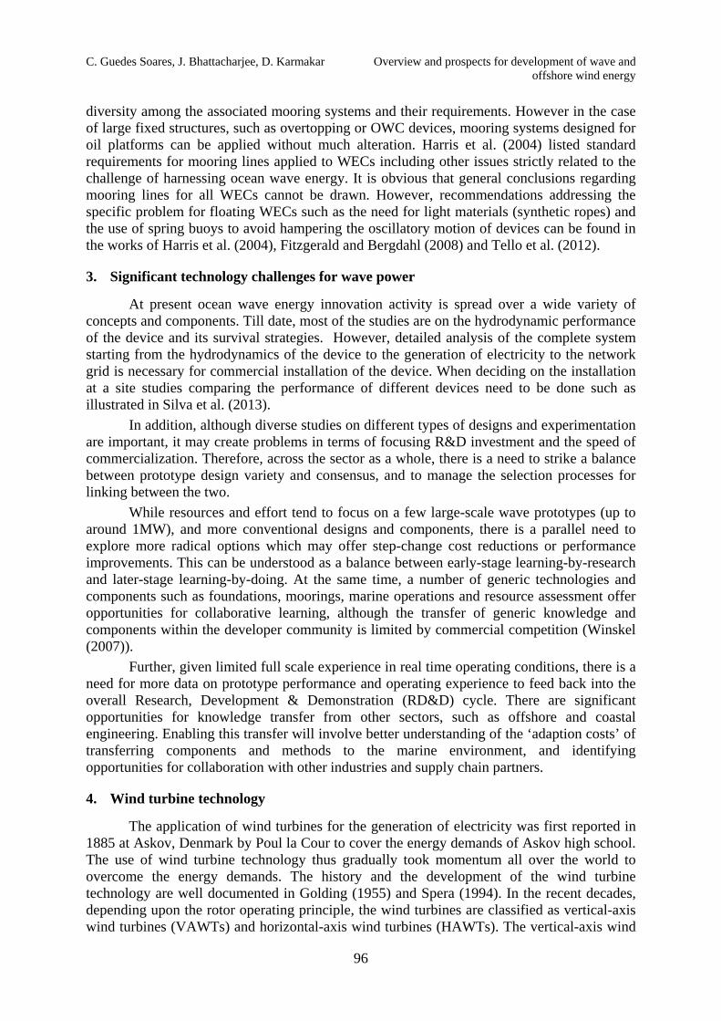
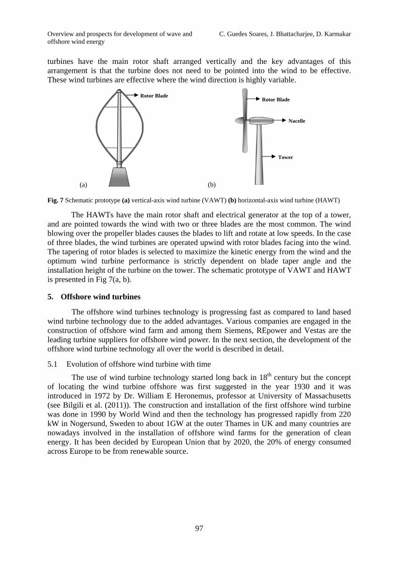
The application of wind turbines for the generation of electricity was first reported in 1885 at Askov, Denmark by Poul la Cour to cover the energy demands of Askov high school. The use of wind turbine technology thus gradually took momentum all over the world to overcome the energy demands. The history and the development of the wind turbine technology are well documented in Golding (1955) and Spera (1994). In the recent decades, depending upon the rotor operating principle, the wind turbines are classified as vertical-axis wind turbines (VAWTs) and horizontal-axis wind turbines (HAWTs). The vertical-axis wind
Overview and prospects for development of wave and C. Guedes Soares, J. Bhattacharjee, D. Karmakar offshore wind energy
97
turbines have the main rotor shaft arranged vertically and the key advantages of this arrangement is that the turbine does not need to be pointed into the wind to be effective. These wind turbines are effective where the wind direction is highly variable.
(a) (b)
Fig. 7 Schematic prototype (a) vertical-axis wind turbine (VAWT) (b) horizontal-axis wind turbine (HAWT)
The HAWTs have the main rotor shaft and electrical generator at the top of a tower, and are pointed towards the wind with two or three blades are the most common. The wind blowing over the propeller blades causes the blades to lift and rotate at low speeds. In the case of three blades, the wind turbines are operated upwind with rotor blades facing into the wind. The tapering of rotor blades is selected to maximize the kinetic energy from the wind and the optimum wind turbine performance is strictly dependent on blade taper angle and the installation height of the turbine on the tower. The schematic prototype of VAWT and HAWT is presented in Fig 7(a, b).
5. Offshore wind turbines
The offshore wind turbines technology is progressing fast as compared to land based wind turbine technology due to the added advantages. Various companies are engaged in the construction of offshore wind farm and among them Siemens, REpower and Vestas are the leading turbine suppliers for offshore wind power. In the next section, the development of the offshore wind turbine technology all over the world is described in detail.
5.1 Evolution of offshore wind turbine with time
The use of wind turbine technology started long back in 18th century but the concept of locating the wind turbine offshore was first suggested in the year 1930 and it was introduced in 1972 by Dr. William E Heronemus, professor at University of Massachusetts (see Bilgili et al. (2011)). The construction and installation of the first offshore wind turbine was done in 1990 by World Wind and then the technology has progressed rapidly from 220 kW in Nogersund, Sweden to about 1GW at the outer Thames in UK and many countries are nowadays involved in the installation of offshore wind farms for the generation of clean energy. It has been decided by European Union that by 2020, the 20% of energy consumed across Europe to be from renewable source.
Rotor Blade
Nacelle
Tower
Rotor Blade

C. Guedes Soares, J. Bhattacharjee, D. Karmakar Overview and prospects for development of wave and offshore wind energy
98
Fig. 8 Trends of offshore wind turbine size (Fichaux et al., 2011)
The studies carried out by the European Wind Energy Association (EWEA) shows that the countries such as Belgium, Finland, Portugal, Spain, Germany, Ireland, Norway, Sweden, Denmark, UK and Netherlands are actively engaged in the installation of offshore wind turbines. A commercial wind farm at Vindeby, Denmark of rated power 4.95 MW was constructed in 1991. Then in 1995, Denmark constructed another offshore wind farm of 5 MW output and consequently in 2000 Danish offshore wind farm was constructed of rated power 40 MW. Horns Rev offshore wind farm was constructed in 2002 with total output of 160 MW and in 2007, Lillgrund offshore wind farm was constructed with a total power production of 110 MW. The other offshore wind turbine projects carried out are in Belgium, Belwind Phase 1 (165MW), in Denmark, Nysted II/R_dsand II (207MW), in Germany, Alpha Ventus (60MW), in Sweden, Gasslingegrund (30MW), in the UK, Robin Rigg (180MW), Guneet Sands (172.6MW), and Thanet (300MW), Lynn and Inner Dowsing (194 MW), the Kentish Flats project (90 MW) and the Burbo Banks project (90 MW), in the Netherlands, the Q7 project (120 MW) (see Brennan et al. (2012)). The trends of offshore wind turbine size and development is presented in Fig 8.
The International Energy Agency (IEA) and National Renewable Energy Laboratory (NREL) are working on the research and developments of offshore floating wind turbines in deep water areas. In Portugal a 2 MW prototype offshore wind turbine has been installed on the floating platform WindFloat developed by Principle Power. In the next phase an additional 5 MW turbine is planned to follow and it is proposed to achieve a total capacity of 150 MW. Significant efforts have been made to implement this modified turbine structure, especially in Norway (Skaare et al. 2006, 2007), the United States of America (Wayman et al. (2006), Jonkman and Bhul, (2007)) and Japan (Suzuki and Sato, 2006)). A floating wind turbine prototype has been put into real sea test in Norway in 2009 (Nielsen et al. (2009)) and a detailed literature survey on offshore floating wind turbine are presented in Wang et al. (2010) and Bagbanci et al. (2012).
6. Classification of offshore wind turbines
The offshore wind turbines are in general classified as (i) Shallow water foundation, (ii) Transitional water foundation and (iii) Deep water foundation, depending upon the water depths. The shallow water wind turbines are generally placed in between 5m - 30m water depth and the transitional offshore wind turbine are placed between 30m - 60m water depth. Both these shallow water and transitional offshore wind turbines are having fixed foundations whereas the deep water offshore wind turbines are generally floating structures and are placed in more than 60m water depth. The floating wind turbines in deep water fall into four main

Overview and prospects for development of wave and C. Guedes Soares, J. Bhattacharjee, D. Karmakar offshore wind energy
99
categories (i) Spar-buoy type, (ii) Tension Leg Platform (TLP) type, (iii) Semi-submersible type and (iv) Pontoon type. So far, most projects of offshore wind farms are located in relatively shallow water using bottom-fixed type wind turbines. To extend wind turbine systems to deeper water, practical research of offshore floating wind turbine systems is required. Also, developing offshore floating wind farms is important because it can provide high wind speed by low surface roughness, and make use of extremely abundant deep water wind resources with the additional advantages of minimizing the scenery disturbance and avoiding the noise problems generated by wind-driven blades.
6.1 Fixed offshore wind turbines
The offshore fixed support structures for wind turbines are used mainly for shallow and intermediate water depths. These fixed support structures are designed and built based on the design principles of the oil and gas industry. In offshore regions the support structure is having the dominant loading from wind and wave loads, so an integrated analysis is required. The offshore wind energy began in shallow waters of the North Sea where the abundance of sites and higher wind resources are more favourable in comparison with Europe’s land-based alternatives. In 1990, the first installation was done in Sweden for a single 300-kW turbine and consequently, the industry has grown very fast in the past 22 years. Here, the discussion will only concentrate on some of the typical fixed offshore wind turbine support structure used in the offshore region of intermediate and shallow water depth.
6.1.1 Monopile structure
The monopile foundation (see Fig 9 (a)) used for the offshore wind turbine consists of a steel pile with a diameter in between 3.5m - 4.5m and the pile is driven some 10m – 20m into the seabed depending on the type of ground. The turbine tower is extended under the water and into the sea bed which also helps in controlling the erosion. The monopiles do not need any seabed preparations but require heavy piling equipment and can be easily transformed from onshore to offshore with minimal design and they leave a minimal footprint to the seabed. These monopile foundations are not well suited for soil strata with large boulders. Additionally the required size of an acceptable monopile increases disproportionately as turbine size increases and site conditions become more challenging. Agarwal and Manuel (2009) performed the simulation of offshore wind turbine response for long term extreme loads prediction. Recently, Bagbanci et al. (2012) studied the effect of environment on the design loads on 5MW offshore monopole wind turbine.
6.1.2 Gravity base
The gravity base foundations were used by most of the existing offshore wind parks in shallow water region. The foundation is similar to monopile foundation and it relies on gravity to keep the turbine in place. The gravity base foundations (see Fig 9 (b)) require well prepared seabed to ensure horizontal smooth ground for foundation. These gravity based foundations can be manufactured with reinforced concrete or steel and the studies carried out in Denmark have shown that steel is better foundation solution than concrete in large offshore wind farms.
The gravity based foundation using steel is a cylindrical steel tube placed on a flat steel box on the sea bed. The steel foundations are filled with olivine, which gives the foundations sufficient weight to withstand waves and pressure. A steel gravity foundation is considerably lighter than concrete foundations but it gives as good rigidity and stability as concrete. This gravity base alternative has not flair for flexibility like monopile but costs increase rabidly when water depth increases.

C. Guedes Soares, J. Bhattacharjee, D. Karmakar Overview and prospects for development of wave and offshore wind energy
100
Fig. 9 Prototype (a) monopile wind turbine and (b) gravity base wind turbine and (c) jacket type wind turbine
(Musial and Butterfield (2006))
6.1.3 Suction bucket
A suction bucket foundation consists of an upside down cylinder that is pressed into the subsoil. The bucket penetrates into the seabed partly by self-weight and partly by applied suction. Suction buckets are tubular steel foundations that are installed by sealing the top and applying suction inside the bucket. The hydrostatic pressure difference and the deadweight cause the bucket to penetrate the soil. This procedure allows the buckets to be connected to the rest of the structure before installation, enabling a reduction in steps of the installation procedure. This system has been tried in practice in the Norwegian oil and gas fields in the North Sea and in Angola. Due to large hydrostatic force that is required for installation, suction buckets commonly have a much lower aspect ratio than driven piles. It is observed that the diameter to length ratio of 10 is a practical maximum and it depends on water depth and soil properties.
6.1.4 Jacket support structure
The jacket type support structures (see Fig 9(c)) for offshore wind turbine are in general used for intermediate water depth. This type of support structures can also be used for higher water depths but the construction costs of jacket support structures are very high for higher water depth. These types of support structures are most common in oil and gas industries but for offshore wind energy application they are suitable for moderate water depths. In UK and Germany the jacket type wind turbines were installed in the Beatrice wind farm and Alpha Ventus wind farm as reported in Brennan et al. (2012). A lot of studies on these jacket type structures were carried out by Seidal (2007), Long and Moe (2007), Vemula et al. (2010) and Gao et al. (2010).
6.2 Design challenges of fixed offshore wind turbine
The fixed offshore wind turbine operating in the shallow and intermediate water depth region often face design challenges when they are used in the deep water regions. So the design challenges of fixed offshore wind turbines are as follows
• The cost of the support structure for the wind turbine increases with increase in the water depth and as a consequence the entire wind turbine lifecycle including the phases of design, installation, operation and maintenance cost increases.

Overview and prospects for development of wave and C. Guedes Soares, J. Bhattacharjee, D. Karmakar offshore wind energy
101
• The dynamic loading of the high power rated wind turbine increases significantly and as a result the aerodynamic loads induces high dynamic amplification to the support structure which may result in design challenge.
• In the case of fixed type support structure for deep water depth the hydrodynamic load on the structure may lead to fatigue damage.
So, in order to overcome these shortcomings of fixed offshore support structure for wind turbine in deep water region, the wind turbines need to be installed over floating foundations. In the next section the detailed study on the floating offshore wind turbine are discussed.
6.3 Floating offshore wind turbines
The floating offshore wind turbine concept is developed for the installation of wind turbines in the deep water regions. At present, there are a number of offshore wind turbines floating foundation concepts in various stages of development and the main concern is to study the floating wind turbine in deep water depth where the generation of power of each unit can be increased as compared to fixed support structures. The different type of offshore floating foundation for wind turbines are classified as spar-type, TLP type, Semi-submersible type and pontoon type structures.
6.3.1 Spar-type floating wind turbine
The spar-type floating foundation consists of a steel or concrete cylinder filled with a ballast of water and gravel to keep the centre of gravity well below the centre of buoyancy which ensures the wind turbine floats in the sea and stays upright since it creates a large righting moment arm and high inertial resistance to pitch and roll motions. The floater is ballasted by permanent solid iron ore ballast, concrete or gravel from a chute. The draft of the floating foundation is usually larger than or at least equal to the hub height above the mean sea level for stability and to minimize heave motion. The spar-type floating wind turbine is usually kept in position by a taut or a catenary spread mooring system using anchor-chains, steel cables or synthetic fibre ropes. The first full scale size spar floating turbine has been deployed off the south-west coast of Karmoy Island, Norway by Statoil in the Hywind demonstration project.
The studies on the spar-type floating wind turbine (see Fig 10(a)) are carried out by various researchers in the recent decades and among them are Tong (1998), Nielson et al. (2006), Skaare et al. (2007), Suzuki and Sato (2007), Matsukuma and Utsunomiya (2008), Utsunomiya et al. (2009) and Karimirad and Moan (2010). Recently, Bagbanci et al. (2011a) studied the dynamic analysis of spar-type floating wind turbine and Bagbanci et al. (2011b) performed a brief comparison of spar-type and barge-type offshore floating wind turbine.
6.3.2 Tension leg platform (TLP) type floating wind turbine
The TLP type floating foundation is most common in offshore oil and gas industry. The conventional TLP platform comprises a square pontoon with columns on which the topside deck rests. A smaller version of this conventional hull form is the mini-TLP which has been adopted by the TLP-type floating wind turbine. The TLP wind turbine are assembled and commissioned onshore thereby avoiding the logistical difficulties of offshore assembly. The fully fitted up platform is towed to the deployment site thus precluding the need to charter and mobilize expensive heavy-lift vessels or derrick crane barges for offshore construction. The floating platform is held in position by vertical tendons which are anchored either by a template foundation, suction caissons or by pile driven anchors and the pre-tensioned tethers provide the righting stability.

C. Guedes Soares, J. Bhattacharjee, D. Karmakar Overview and prospects for development of wave and offshore wind energy
102
Fig. 10 Prototype (a) spar-type wind turbine and (b) TLP type wind turbine (c) semi-submersible type wind turbine and (d) pontoon type wind turbine (Wang et al. (2010)).
A TLP wind turbine (see Fig 10(b)) has since been installed off the coast of Puglia, southern Italy by Blue H Technologies. This large scale prototype is used to test the assembly, transportation and installation of the TLP type wind energy converter as well as to serve as a metering platform with sensors to measure site specific data. The studies on the TLP type offshore floating wind turbine is carried out by Withee and Sclavounos (2004), Lee (2004), Suzuki et al. (2009), Weinzettel et al. (2009), Bae et al. (2010) and Nihei and Fujioka (2010).
6.3.3 Semi-submersible type floating wind turbine
The semi-submersible type comprises a few large columns connected to each other by tubular members. A wind turbine may sit on one of the columns or there can be wind turbines sitting on all the columns. Alternatively, the wind turbine may be positioned at the geometric centre of the columns and supported by lateral bracing members. The columns provide the ballast and they are partially filled with water. When in the afloat condition, the water-plane area of the columns primarily provides floatation stability. This design is good in providing stability to the wind turbine and its relatively shallow draft allows for site flexibility. The semi-submersible floating wind turbine is kept in position by mooring lines.
This semi-submersible type (see Fig 10(c)) floating wind turbine may be constructed onshore and until now, Principle Power Inc. is promoting the semi-submersible type which consists of three column tubes with patented horizontal water entrapment heave plates at the bases. The research is still carried on the semi-submersible floating foundation and among them are Henderson and Patel (1998), Zambrano et al. (2006), Shimada et al. (2007) and Ishihara et al. (2007a,b, 2008), Ishihara et al. (2009), Roddier et al. (2009), Cermelli et al. (2009) and Aubault et al. (2009).
6.3.4 Pontoon type floating wind turbine
The pontoon type floating wind turbine has a very large pontoon structure to carry a group of wind turbines. The large pontoon structure achieves stability via distributed buoyancy and by taking advantage of the weighted water plane area for righting moment and may be moored by conventional catenary anchor chains. Based on the buoyancy stabilized concept, NREL and MIT collaborated in a pontoon-type floating wind turbine (see Fig 10(d)). The pontoon-type is adopted because of its simplicity in design, fabrication and installation. The study on the pontoon-type floating foundation is carried out by Jonkman and Buhl (2007), Wayman et al. (2006) and Iijima et al. (2010).

Overview and prospects for development of wave and C. Guedes Soares, J. Bhattacharjee, D. Karmakar offshore wind energy
103
7. Coupled dynamic analysis of floating wind turbine
The studies on the floating offshore wind turbine concepts are carried out by various researchers all over the world and this has led to the development of numerical codes for the dynamic analysis of offshore wind turbines where hydrodynamic, aerodynamic, structural and response due to control system are taken into account. In general, for the design and analysis of the wind turbine system, the time domain analysis is widely used whereas in oil and gas industry frequency domain analysis is used. Various offshore wind turbine codes that were used today are FAST, FLEX5, Bladed, Bladed Multibody, ADAMS, SIMPACK, HAWC, HAWC2, BHawC and ADCoS-Offshore. Among all these codes FAST is frequently used for the analysis of offshore wind turbines.
The wind turbine modelled using the FAST (Fatigue, Aerodynamics, Structures, and Turbulence) is promoted by the National Renewable Energy Laboratory (NREL) in conjunction with ADAMS (Automatic Dynamic Analysis of Mechanical Systems), which is a commercially available software that is widely used to model mechanical systems (Jonkman and Buhl (2004a,b), Jonkman (2009, 2010)). FAST codes modelling the floater loading and mechanical properties are coupled to the ADAMS wind turbine model to determine the effect on the wind turbine components. The hydrodynamic studies can be conducted using WAMIT and then it can be coupled with FAST code to obtain aero-servo-hydro-elastic simulations. The CHARM3D is also used in the study of offshore wind turbine which is a time domain numerical code and is also coupled with FAST to analyse the mooring lines of the floater. Presently, IEA is continuing with the IEA Wind Task project for Offshore Codes Comparison Collaboration Continuation (OC4) for TLP type and semi-submersible type floating offshore wind turbines.
8. Present status of wave energy compared to wind energy
Although energy density is much higher in ocean wave than wind, exploitation of wave energy has lagged behind that of wind (Falcão (2010)). The primary reason behind this global scenario is probably due to the steady progression of wind energy exploitation from land-based to near-shore locations and further out to sea in the past few decades (Brennan et al. (2012)). The main disadvantage of capturing wave power compared to wind is its random variability in several time-scales, from wave to wave, with sea state, and from month to month. Optimal wave energy absorption involves some kind of resonance, thus the geometry and size of the structure are linked to wavelength. Hence, if pilot plants are to be tested in the open ocean, they must be large structures. In wind turbine industry (namely in Denmark), relatively small machines were developed first, and were subsequently scaled up to larger sizes and powers as the market developed. However, in the wave energy technology, high costs of constructing, deploying, maintaining and testing large prototypes under sometimes very harsh environmental conditions, has hindered the development of wave energy systems; in most cases such operations were possible only with substantial financial support from governments. The wind turbine technology has advantages as compared to wave energy. The major benefit of wind turbine technology is that it can offer cost-effective solutions that in the long term it can compete with energy from conventional sources. Furthermore, the installation offshore does not jeopardize the value of a home, office building or commercial building as can happen onshore.
9. Conclusions
In the recent years a lot of wave energy devices are developed and the challenges associated with wave energy are similar than those associated with wind energy. A larger

C. Guedes Soares, J. Bhattacharjee, D. Karmakar Overview and prospects for development of wave and offshore wind energy
104
number of devices have been tested as proto-type model test and the ideas on the wave power generation were also fully studied. The primary challenges for WECs are the cost reduction, including for moorings and deployment systems in addition to fatigue resistance. In general, the development, from concept to commercial stage, has been found to be a difficult, slow and expensive process.
In addition to the progress in the model testing a substantial study in the theoretical and numerical modelling of wave energy converters and their energy conversion chain has been widely carried out. In parallel to the development of wave power, the offshore wind technology has also taken a big step in the deployment of large scale offshore wind farms based on bottom-fixed support structures. In the recent years, a number of concepts demonstrating floating wind turbines have come up but the primary focus and major challenge is in reduction of capital and operational cost. Although design rules for bottom-fixed offshore wind turbines are in development, design rules for floating wind turbines is also initiated and covers a large variety of floating concepts.
The experience in the offshore oil and gas industry is valuable for such developments, but the design requirements needs to be properly studied due to the unmanned nature and economic constraints for fixed and floating wind turbines. In order to properly carry out structural design, various simulation tools needs to be addressed not only aerodynamic and hydrodynamic loads, but also the structural responses of the rotor, tower and floating/mooring systems, as well as control strategy. In this respect offshore wind structural analysis can be more complex than for oil and gas structures, however, machine loading can be monitored and controlled meaning greater scope for progressive life- cycle strategies. In the coming years, due to the progress in the R&D activities in wave and wind energy utilization, the future designs can take full advantage of this experience and of the new emerging modelling techniques. In addition, the focus will be on array optimization and cost reduction for large volume manufacture, deployment and operation.
Acknowledgement
This work was performed within the project “FLOATERS” financed by the Portuguese Foundation for Science and Technology (Fundação para a Ciência e Tecnologia) under contract PTDC/ECM/111242/2009. The second and third authors have been funded by the Portuguese Foundation for Science and Technology (FCT, Fundação para a Ciência e a Tecnologia, Ministério da Ciência, Tecnologia e Ensino Superior) through Post-Doctoral Fellowships under the contracts no. SFRH/BPD/47210/2008 and SFRH/BPD/81010/2011.
REFERENCES
[1]. Agarwal, P. and Manuel, L. 2009. Simulation of offshore wind turbine response for long-term extreme load prediction, J. of Eng. Struct. 31, pp. 2236-2246.
[2]. Alcorn, R., Hunter, S., Signorelli, C., Obeyesekera, R., Finnigan, T. and Denniss, T. Results of the testing of the Energetech wave energy plant at Port Kembla. Energeth Report; 2005.
[3]. Aubault, A., Cermelli, C., and Roddier, D., 2009. WIND FLOAT: a floating foundation for offshore wind turbines Part III: structural analysis. Proc. 28th Intl Conf. on Ocean, Offshore and Arctic Eng., Honolulu, Hawaii, USA, OMAE-79232.
[4]. Bae, Y. H., Kim, M. H., and Shin, Y. S., 2010. Rotor-floater mooring coupled dynamic analysis of mini TLP-type offshore floating wind turbines. Proc. 29th Intl. Conf. on Ocean, Offshore and Arctic Eng., OMAE-20555.
[5]. Bilgili, M., Yasar, A. and Simsek, E. 2011. Offshore wind power development in Europe and its comparison with onshore counterpart. Renewable and Sustainable Energy Reviews; Vol. 15, pp. 905-915.

Overview and prospects for development of wave and C. Guedes Soares, J. Bhattacharjee, D. Karmakar offshore wind energy
105
[6]. Bagbanci, H., Karmakar, D. and Guedes Soares, C. 2011a. Dynamic analysis of spar-type floating offshore wind turbine. 2nd Coastal and Maritime Mediterranean Conference CM2-2011, Tangier, Morocco, pp. 407-412.
[7]. Bagbanci, H., Karmakar, D. and Guedes Soares, C. 2011b. Comparative study on the coupled dynamic analysis of spar-type and barge-type floating wind turbine. 1st Intl. Conference on Naval Architecture and Marine and Engineering, INT-NAM 2011, Turkey, Istanbul.
[8]. Bagbanci, H., Karmakar, D. and Guedes Soares, C. 2012. Review of offshore floating wind turbine concepts, Maritime Engineering and Technology, C. Guedes Soares et al. (Eds.), Taylor & Francis Group, London, pp 553-562.
[9]. Bagbanci, H., Karmakar, D. and Guedes Soares, C. 2012. Effect of environment on the design loads on monopole offshore wind turbine, Maritime Engineering and Technology, C. Guedes Soares et al. (Eds.), Taylor & Francis Group, London, pp 547-552.
[10]. Bernhoff, H., Sjöstedt E. and Leijon M., 2006. Wave energy resources in sheltered sea areas: a case study of the Baltic Sea. Renewable Energy, 31, 2164-70.
[11]. Brennan, F. P., Gao, Z., Landet, E., Boulluec, M. L., Rim, C. W., Sirkar, J., Sun, L., Suzuki, H., Thiry, A., Trarieux, F. and Wang, C. M. 2012. Offshore Renewable energy, ISSC Committee report V.4, 18th International Ship and Offshore Structures Congress, Rostock, Germany, Vol. 2, pp. 153-207.
[12]. Cermelli, C., Roddier, D. and Aubault, A. 2009. WINDFLOAT: a floating foundation for offshore wind turbines Part II: Hydrodynamics analysis. Proc. 28th Intl Conf. on Ocean, Offshore and Arctic Eng., Honolulu, Hawaii, USA, Paper OMAE2009-79231.
[13]. Clément, A., McCullen, P., Falcão, A., Fiorentino, A., Gardner, F., Hammarlund, K., Lemonis, G., Lewis, T., Nielsen, K., Petroncini, S., Pontes, M.-T., Schild, P., Sjöström, B.O., Sørensen, H., C. and Thorpe, T. 2002. Wave energy in Europe: current status and perspectives. Renewable and Sustainable Energy Reviews, Vol. 6(5), pp. 405–31.
[14]. Cruz, J., editor. Ocean wave energy. Berlin: Springer, 2008. [15]. Defne, Z., Haas, K.A., and Fritz, H.M., 2009. Wave power potential along the Atlantic coast of the
southeastern USA. Renewable Energy, 34, 2197-2205. [16]. Duckers, L. Wave energy. In Renewable energy (Ed. G. Boyle), 2nd edition, 2004, Ch. 8 Oxford
University Press, Oxford, UK. [17]. Dunnett, D, and Wallace, JS., 2009. Electricity generation from wave power in Canada. Renewable
Energy, 34(1), 179-195 [18]. Drew, B., Plummer, A. R. and Sahinkaya M. N. 2009. A review of wave energy converter technology, J.
Power and Energy, Vol. 223, pp. 887-902. [19]. Elwood, D., Yim, S. C., Prudell, J., Stillinger, C., von Jouanne, A., Brekken, T., Brown, A. and Paasch.
R. 2010. Design, Construction, and Ocean Testing of a Taut- Moored Dual-Body Wave Energy Converter with a Linear Generator Power Take-off., Renewable Energy, Vol. 35(2), pp. 348-354.
[20]. Eriksson, M., Isberg. J. and Leijon, M. 2005. Hydrodynamic modelling of a direct drive wave energy converter. Int. J. Engineering Science, Vol. 43, pp. 1377-1387.
[21]. Estefen, S. F., Esperança, P. T. T., Ricarte, E., Costa, P. R., Pinheiro, M. M., Clemente, C. H., et al. 2008. Experimental and numerical studies of the wave energy hyperbaric device for electricity production. Proc. of 27th Int. Conf. Offshore Mechanics Arctic Engineering, Estoril, Portugal; paper no.OMAE2008-57891.
[22]. Falcão, A. F.de O., 2010. Wave energy utilization: A review of the technologies. Renewable and Sustainable Energy Reviews, Vol. 14, pp. 899-918.
[23]. Falnes, J. 1999. Wave-energy conversion through relative motion between two single-mode oscillating bodies. J Offshore Mech. Arctic Eng., Vol. 121, pp. 32–8.
[24]. Falnes, J., Ocean Waves and Oscillating Systems: Linear interactions including wave-energy extraction, Cambridge University Press, UK, 2004.
[25]. Falnes, J. 2007. A review of wave-energy extraction. Marine Structures, Vol. 20, pp. 185-201. [26]. Fichaux, N., Beurskens, J., Jensen, P. H. and Wilkes, J. 2011. Final Report – UpWind-Design limits and
solutions for very large wind turbines. The EU FP6 Project UpWind, Contract No. 019945 (SES6). [27]. Fitzgerald, J. and Bergdahl, L. 2008. Including moorings in the assessment of a generic offshore wave
energy converter: A frequency domain approach. Marine Structures, Vol. 21(1), pp. 23-46.

C. Guedes Soares, J. Bhattacharjee, D. Karmakar Overview and prospects for development of wave and offshore wind energy
106
[28]. Gao, Z., Saha, N., Moan, T. and Amdahl, J. (2010). Dynamic analysis of offshore fixed wind turbines under wind and wave loads using alternative computer codes. In: Proceedings of the 3rd Conference on the Science of making Torque from Wind, June 28-30, Heraklion, Greece.
[29]. Golding, E. W. 1955. The generation of electricity from wind power. E. & F. N. Spon (reprinted R. I. Harris, 1976).
[30]. Gomes, R. P. F., Henriques, J. C. C., Gato, L. M. C. and Falcão, A. F. O. 2010. IPS Two-body Wave Energy Converter: Acceleration Tube Optimization, Proceedings of the Twentieth International Offshore and Polar Engineering Conference, Beijing, China, June 20 25, 2010.
[31]. Gonçalves, M., Martinho, P. and Guedes Soares, C., 2014. Wave energy conditions in the western French coast. Renewable Energy, 62, 155-163.
[32]. Gonçalves, M.; Martinho, P., and Guedes Soares, C. 2013. Assessment of wave energy in the Canary Islands. Renewable Energy.(accepted)
[33]. Guedes Soares, C., Bhattacharjee, J., Tello, M., and Pietra, L. Review and classification of Wave Energy Converters. C. Guedes Soares, Y. Garbatov S. Sutulo T. A. Santos, (Eds.). Maritime Engineering and Technology. 2012, pp. 585-594.
[34]. Harris, R. E., Johanning, L. and Wolfram, J., 2004. Mooring systems for wave energy converters: A review of design issues and choices. 3rd International Conference on Marine Renewable Energy, Blyth, UK.
[35]. Henderson, R., 2006. Design, simulation, and testing of a novel hydraulic power take-off system for the Pelamis wave energy converter, Renewable Energy, Vol. 31, pp. 271–283.
[36]. Henderson, A. R. and Patel, M. H., 1998. Floating offshore wind energy. Proc. of 17th Intl Conf. on Ocean, Offshore and Arctic Eng., Lisbon, Portugal, July 5–9.
[37]. Hong, D. C., Hong, S. Y., and Hong, S. W., 2004 Numerical Study on the Reverse Drift Force of Floating BBDB Wave Energy Absorbers, Ocean Engineering, Vol. 31, No 10, pp. 1257-1294.
[38]. Hotta, H., Washio, Y., Yokozawa, H. and Miyazaki, T. 1996, R&D on wave power device “Mighty Whale”, Renewable Energy, Vol. 9, pp. 1223-1226.
[39]. Iglesias, G. and Carballo, R., 2009. Wave energy potential along the death coast (Spain). Energy, 34(11), 1963–75.
[40]. Iglesias, G. and Carballo, R., 2010. Wave energy and nearshore hot spots: The case of the SE Bay of Biscay. Renewable Energy, 35, 2490-2500.
[41]. Iglesias G., Carballo R. Wave power for La Isla Bonita. Energy. 2010, 35:5013- 5021 [42]. Iglesias G., Carballo R. Wave resource in El Hierro - an island towards energy self-sufficiency.
Renewable Energy. 2011, 36:689-698 [43]. Iijima, K., Kim, J. and Fujikubo, M., 2010. Coupled aerodynamic and hydroelastic analysis of an offshore
floating wind turbine system under wind and wave loads. Proc. 29th Intl. Conf. on Ocean, Offshore and Arctic Eng., Paper OMAE2010-20772.
[44]. Ishihara, T., Phuc, P. V., and Sukegawa, H., 2007a. Numerical study on the dynamic response of a floating offshore wind turbine system due to resonance and nonlinear wave. Proc. 2nd EOW, Berlin, Germany.
[45]. Ishihara, T., Phuc, P. V., and Sukegawa, H., 2007b. A study on the dynamic response of a semi-submersible floating offshore wind turbine system Part 1: a water tank test. Proc. 12th Intl. Conf. on Wind Engineering, Cairns, Australia.
[46]. Ishihara, T., Waris, M. B., and Sukegawa, H., 2009. A study on influence of heave plate on dynamic response of floating offshore wind turbine system. Proc. 3rd European Offshore Wind Conference and Exhibition, Stockholm, Sweden.
[47]. Jonkman, J. M. 2009. Dynamics of offshore floating wind turbine model development and verification, Wind Energy, Vol. 12, pp. 459-492.
[48]. Jonkman, J. M. 2010. Defination of the floating system for phase IV of OC3, NREL technical report, pp. 1-25.
[49]. Jonkman, J. M. and Buhl, M. L. Jr. 2004a. New Developments for the NWTC’s FAST Aeroelastic HAWT Simulator, ASME Wind Energy Symposium, 42nd AIAA Aerospace Sciences Meeting and Exhibit, Reno Nevada, USA, New York.
[50]. Jonkman, J. M. and Buhl, M. L. Jr. 2004b. FAST User’s Guide, NREL/EL-500-29798, Golden, CO: National Renewable Energy Laboratory.

Overview and prospects for development of wave and C. Guedes Soares, J. Bhattacharjee, D. Karmakar offshore wind energy
107
[51]. Jonkman, J. M. and Buhl, M. L. Jr, 2007. Loads analysis of a floating offshore wind turbine using fully coupled simulation. Proc. of Wind Power 2007 Conference and Exhibition, Los Angeles, California.
[52]. Joselin Herbert, G. M., Iniyan, S., Sreevalsan, E. and Rajapandian, S. 2007. A review of wind energy Technologies, Renewable and Sustainable Energy Reviews, Vol. 11, pp. 1117–1145.
[53]. Karimirad, M. and Moan, T., 2010. Extreme structural response of a spar type wind turbine. Proc. 29th Intl. Conf. on Ocean, Offshore and Arctic Engineering, OMAE-20044.
[54]. Kim, G, Jeong, WM, Lee, KS, Jun, K, Lee, ME., 2011. Offshore and nearshore wave energy assessment around the Korean Peninsula. Energy, 36(3), 1460-1469.
[55]. Kofoed, J. P., Frigaard, P., Friis-Madsen, E., Sørensen, H. C. 2006. Prototype testing of the wave energy converter wave dragon. Renewable Energy, Vol. 31, pp. 181-189.
[56]. Korde, U. A. 2000. A note on the hydrodynamics of a tail tube buoy. Ocean Engng., Vol. 27, pp. 1473-1484.
[57]. Lee, K. H., 2004. Responses of floating wind turbines to wind and wave excitation. Thesis (MSc). Massachusetts Institute of Technology.
[58]. Lendenmann, H., Strømsem, K.-C., Dai Pre, M., Arshad, W., Leirbukt, A., Tjensvoll, G. and Gulli, T. 2007. Direct generation wave energy converters for optimized electrical power production. Proceedings of 7th European Wave Tidal Energy Conference.
[59]. Leijon, M., Danielsson, O., Eriksson, M., Thorburn, K., Bernhoff, H., Isberg, J., et al. 2006. An electrical approach to wave energy conversion. Renewable Energy, Vol. 31(9), pp. 1309–19.
[60]. Long, H. Y. and Moe, G. 2007. Truss type towers in offshore wind turbines. In: Proceedings of the European O_shore Wind Conference and Exhibition, December 4-6, Berlin, Germany.
[61]. Lye, J. L., Brown, D. T. and Johnson, F. 2009. An investigation into the non-linear effects resulting from air cushions in the Orecon oscillating water column (OWC) device. Proc. of 28th Int. Conf. on Ocean Offshore Arctic Engineering, Honolulu, Hawaii; paper no. OMAE2009-79115.
[62]. McCabe, A. P., Bradshaw, A., Meadowcroft, J. A. C. and Aggidis, G. 2005. Developments in the design of the PS Frog Mk 5 wave energy converter. Renewable Energy, Vol. 31, pp. 141–51.
[63]. McCormick, M. E. 1976. A modified linear analysis of a wave-energy conversion buoy, Ocean Engng. Vol. 3, pp.133-144.
[64]. McCormick, M. E. Ocean wave energy conversion. New York: Wiley; 1981. [65]. McCormick, M. E., Murthagh, J. and McCabe, P. 1998. Large-scale experimental study of a hinged-barge
wave energy conversion system. Proc. 3rd European Wave Energy Conference; pp. 215–22. [66]. Margheritini, L., Vicinanza, D. and Frigaard, P. 2009. SSG wave energy converter: Design, reliability and
hydraulic performance of an innovative overtopping device, Renewable Energy, Vol. 34, pp. 1371–1380. [67]. Marquis, L., Kramer, M. and Frigaard, P., 2010. First Power Production Results from the Wave Star
Roshage Wave Energy Converter, Proc. 3rd Int. Conf. on Ocean Energy (ICOE 2010), 6 October, Bilbao. [68]. Masuda, Y., Kimura, H., Liang, X., Gao, X., Mogensen, R. M. and Andersen, T. 1995. Regarding BBDB
wave power generation plant. In: Proceedings of 2nd European Wave Power Conference, Lisbon, Portugal. pp. 69–76.
[69]. Masuda, Y. 1971.Wave-activated generator. Int. Colloq Exposition Oceans. France: Bordeaux. [70]. Matsukuma, H. and Utsunomiya, T., 2008. Motion analysis of a floating offshore wind turbine
considering rotor rotation The IES Journal Part A: Civil and Structural Eng., Vol. 1 (4), pp. 268–279. [71]. Musial, W. and Butterfield, S. 2006. Energy from offshore wind. Offshore Technology Conf., OTC
18355 (OER), Houston. [72]. Mynett, A. E., Serman, D. D. and Mei, C. C. 1979. Characteristics of Salter's cam for extracting energy
from ocean waves, Appl. Ocean Res., Vol. 1(1), pp. 13-20. [73]. Nielsen, F. G., Hanson, T. D. and Skaare, B., 2006. Integrated dynamic analysis of floating offshore wind
turbines. Proc. 25th Intl. Conf. Offshore Mechanics and Arctic Eng. Hamburg, Germany, OMAE2006-92291.
[74]. Nielsen, F. G., Argyriadis, K., Fonseca, N., Le Boulluec, M., Liu, P., Suzuki, H., Sirkar, J., Tarp-Johansen, N.J., Turnock, S.R., Waegter, J. and Zong, Z. 2009. Ocean, Wind and wave energy utilization. 17th Intl. Ship and Offshore Structures Congress, Seoul, Korea, pp. 201-257.
[75]. Nihei, Y. and Fujioka, H., 2010. Motion characteristics of a TLP type offshore wind turbine in waves and wind. Proc. 29th Intl. Conf. on Ocean, Offshore and Arctic Eng., OMAE-21126.

C. Guedes Soares, J. Bhattacharjee, D. Karmakar Overview and prospects for development of wave and offshore wind energy
108
[76]. Price, A. A. E. 2009. New Perspectives on Wave Energy Converter Control, Ph. D. thesis, University of Edinburg, UK. (available online at http://lac-repo-live7.is.ed.ac.uk/handle/1842/3109)
[77]. Retzler, C. 2006. Measurements of the slow drift dynamics of a model Pelamis wave energy converter, Renewable Energy, Vol. 31, pp. 257–269.
[78]. Roddier, D., Cermelli, C. and Weinstein, A., 2009. WINDFLOAT: a floating foundation for offshore wind turbines Part I: Design basis and qualification process. Proc. 28th Intl. Conf. on Ocean, Offshore and Arctic Eng., Honolulu, Hawaii, USA, OMAE2009-79229.
[79]. Ross, D. Power from sea waves. Oxford: Oxford University Press; 1995. [80]. Rusu, E. and Guedes Soares, C., 2012a. Wave energy pattern around the Madeira islands. Energy, 45,
771-785. [81]. Rusu, E. and Guedes Soares, C., 2009. Numerical modelling to estimate the spatial distribution of the
wave energy in the Portuguese nearshore. Renewable Energy, 34(6), 1501-1516. [82]. Rusu, L. and Guedes Soares, C., 2012b. Wave energy assessments in the Azores islands. Renewable
Energy, 45, 183-196. [83]. Salter, S. H. 1974. Wave power. Nature, Vol. 249(5459), pp. 720–724. [84]. Salter, S. H. 1993. Changes to the 1981 Design of Spine-based Ducks, Proceedings of the First European
Wave Power Conference, Edinburgh, UK. [85]. Salter, S. H., Taylor, J. R. M. and Caldwell, N. J. 2002. Power conversion mechanisms for wave energy.
J. Engineering for the Maritime Environment, Vol. 216, pp. 1-27. [86]. Seidel, M. 2007. Jacket substructures for the REpower 5M wind turbine. In: Proceedings of the European
Offshore Wind Conference and Exhibition, December 4-6, Berlin, Germany. [87]. Shimada, K., Ohyama, T., Miyakawa, M., Ishihara, T., Phuc, P.V. and Sukegawa, H. 2007. A study on a
semi-submersible floating offshore wind energy conversion system. Proc. 17th Intl. Offshore and Polar Eng. Conf., Lisbon, Portugal, pp. 384–354.
[88]. Silva, D., Rusu, E., and Guedes Soares, C., 2013. Evaluation of various technologies for wave energy extraction in the Portuguese nearshore. Energies, 6, 1344-1364.
[89]. Skaare, B., Hanson, T. and Nielsen, F. G. 2006. Integrated Dynamic Analysis of Floating Offshore Wind Turbines. Proc. European Wind Energy Conf. and Exhibition, Athens, Greece.
[90]. Skaare, B., Hanson, T. and Nielsen, F. G. 2007. Importance of control strategies on fatigue life of floating wind turbines. Proc. 26th Intl. Conf. on Offshore Mechanics and Arctic Eng.. OMAE2007-29277.
[91]. Spera, D. A. 1994. Wind-turbine technology, fundamental concepts of wind-turbine engineering. ASME Press, New York, US.
[92]. Stopa, JE, Cheung, KF, Chen, YL., 2011. Assessment of wave energy resources in Hawaii. Renewable Energy, 36, 554-567.
[93]. Suzuki, H. and Sato, A., 2007. Load on turbine blade induced by motion of floating platform and design requirement for the platform. Proc. 26th Intl. Conf. on Offshore Mechanics and Arctic Eng., OMAE2007-29500.
[94]. Suzuki, H., Kurimoto, M., Kitahara, Y. and Yukinari Fukumoto, Y. 2009. Progressive drifting of floating wind turbines in a wind farm. Proc. 28th Intl. Conf. on Ocean, Offshore and Arctic Eng., Honolulu, Hawaii, OMAE2009-79634.
[95]. Tello, M., Bhattacharjee, J. and Guedes Soares, C. 2012. Dynamics and hydrodynamics of a ship like Wave Energy Converters in roll. C. Guedes Soares, Y. Garbatov S. Sutulo T. A. Santos, (Eds.). Maritime Engineering and Technology. pp. 655-666.
[96]. Thorpe, T. W. A brief review of wave energy, Technical reportno. R120, Energy Technology Support Unit (ETSU). A report produced for the UK Department of Trade and Industry, 1999.
[97]. Tong, K. C., 1998. Technical and economic aspects of a floating offshore wind farm. J. of Wind Eng. and Industrial Aerodynamics, Vol. 74–76, pp. 399–410.
[98]. Torre-Enciso Y, Ortubia I, Ló pez de Aguileta, L. I. and Marqués J. 2009. Mutriku wave power plant: from the thinking out to the reality. In: Proceedings 8th European Wave Tidal Energy Conference, pp. 319–29.
[99]. Utsunomiya, T., Sato, T., Matsukuma, H. and Yago, K. 2009. Experimental validation for motion of a spar-type floating offshore wind turbine using 1/22.5 scale model. Proc. 28th Intl. Conf. on Ocean, Offshore and Arctic Eng., Honolulu, Hawaii, USA, OMAE2009-79695.

Overview and prospects for development of wave and C. Guedes Soares, J. Bhattacharjee, D. Karmakar offshore wind energy
109
[100]. Valério, D., Beirão, P., Sá da Costa, J. 2007. Optimisation of wave energy extraction with the Archimedes Wave Swing. Ocean Engineering; Vol. 34(17-18), pp. 2330-44.
[101]. Vantorre, M., Banasiak, R. and Verhoeven, R. 2004. Modelling of hydraulic performance and wave energy extraction by a point absorber in heave. Applied Ocean Research, Vol. 26, pp. 61-72.
[102]. Vemula, N. K., de Vries, W., Fischer, T., Cordle, A. and Schmidt, B. 2010. Design solution for the UpWind reference offshore support structure (WP4: Offshore foundations and support structures). The EU FP6 Project UpWind, Contract No. 019945 (SES6).
[103]. Wang, C. M., Utsunomiya, T., Wee, S. C. and Choo, Y. S. 2010. Research on floating wind turbines: a literature survey. The IES Journal Part A: Civil and Structural Engineering, Vol. 3(4), pp. 267-277.
[104]. Waters, R., Stalberg, M., Danielsson, O., Svensson, O., Gustafsson, S., Stromstedt, E., et al. 2007. Experimental results from sea trials of an offshore wave energy system. Appl Phys Lett, Vol. 90(3).
[105]. Waters, R, Engström, J, Isberg, J, Leijon, M., 2009. Wave climate off the Swedish west coast. Renewable Energy, 34(6), 1600-1606.
[106]. Wayman, E. N., Sclavounos, P. D., Butterfield, S., Jason, J. and Musial, W. 2006. Coupled dynamic modeling of floating wind turbine systems. Proc. Offshore Technology Conference, Houston, Texas.
[107]. Weber, J., Mouwen, F., Parrish, A. and Robertson, D. 2009. Wavebob-research & development network and tools in the context of systems engineering. In: Proceedings of 8th European Wave Tidal Energy Conference; pp. 416–420.
[108]. Weinstein, A., Fredrikson, G., Parks, M. J. and Nielsen, K., 2004. Aquabuoy, the offshore wave energy converter numerical modeling and optimization, Proc. MTTS/IEEE Techno-Ocean ’04 Conf., Kobe, Japan, Vol. 4, pp. 1854-1859.
[109]. Weinzettel, J., Reenaas, M., Solli, C. and Hertwich, E. G. 2009. Life cycle assessment of a floating offshore wind turbine. Renewable Energy, Vol. 34 (3), pp. 742–747.
[110]. Winskel, M. 2007. Marine energy innovation in the UK energy system: financial capital, social capital and interactive learning. International Journal of Global Energy Issues (IJGEI), Vol. 27, No. 4, 472-491.
[111]. Withee, J. E. and Sclavounos, P. D., 2004. Fully coupled dynamic analysis of a floating wind turbine system. Proc. 8th World Renewable Energy Congress, Denver, USA.
[112]. Zambrano, T., MacCready, T., Kiceniuk, T. Jr.., Roddier, D.G. and Cermelli, C., 2006. Dynamic modeling of deepwater offshore wind turbine structures in Gulf of Mexico storm conditions. Proc. 25th Intl. Con. on Offshore Mechanics and Arctic Eng., Hamburg, Germany, OMAE2006-92029.
Submitted: 01.11.2013 Accepted: 24.02.2014
Carlos GUEDES SOARES Joydip BHATTACHARJEE Debabrata KARMAKAR Centre for Marine Technology and Engineering (CENTEC), Instituto Superior Técnico, Universidade de Lisboa, Av. Rovisco Pais, 1049 001 Lisboa, Portugal Tel: +351 218417957; Fax: +351 218474015 e-mail: [email protected]