outdoor powermax
TRANSCRIPT
PAGE 1 OF 10 214835 REV - RA 7151
Outdoor PowerMAX Modular N+1 Soft-Fail
Phase Combined GaAs System
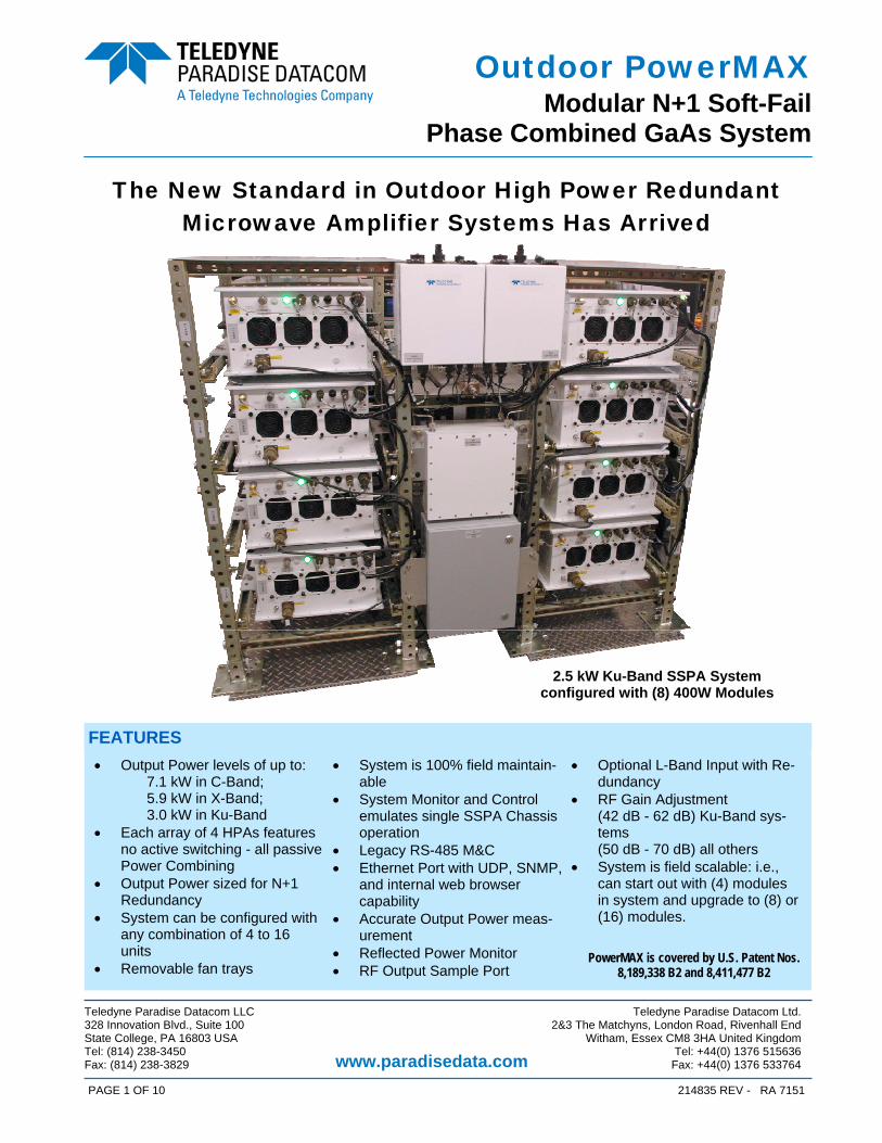
The New Standard in Outdoor High Power Redundant Microwave Amplifier Systems Has Arrived
• Output Power levels of up to: 7.1 kW in C-Band; 5.9 kW in X-Band; 3.0 kW in Ku-Band • Each array of 4 HPAs features
no active switching - all passive Power Combining
• Output Power sized for N+1 Redundancy
• System can be configured with any combination of 4 to 16 units
• Removable fan trays
• System is 100% field maintain-able
• System Monitor and Control emulates single SSPA Chassis operation
• Legacy RS-485 M&C • Ethernet Port with UDP, SNMP,
and internal web browser capability
• Accurate Output Power meas-urement
• Reflected Power Monitor • RF Output Sample Port
• Optional L-Band Input with Re-dundancy
• RF Gain Adjustment (42 dB - 62 dB) Ku-Band sys-tems (50 dB - 70 dB) all others
• System is field scalable: i.e., can start out with (4) modules in system and upgrade to (8) or (16) modules.
FEATURES
PowerMAX is covered by U.S. Patent Nos. 8,189,338 B2 and 8,411,477 B2
Teledyne Paradise Datacom LLC Teledyne Paradise Datacom Ltd. 328 Innovation Blvd., Suite 100 2&3 The Matchyns, London Road, Rivenhall End State College, PA 16803 USA Witham, Essex CM8 3HA United Kingdom Tel: (814) 238-3450 Tel: +44(0) 1376 515636 Fax: (814) 238-3829 Fax: +44(0) 1376 533764 www.paradisedata.com
2.5 kW Ku-Band SSPA System configured with (8) 400W Modules
PAGE 2 OF 10 214835 REV - RA 7151
Outdoor PowerMAX Modular N+1 Soft-Fail
Phase Combined GaAs System
System Operation The Outdoor PowerMAX system maintains complete parallel redundancy down to the embed-ded control level. Therefore the loss of an entire amplifier will not interrupt remote communi-cations with the system. Remote communications can be either RS-485 or Ethernet. The sys-tem will automatically correct its gain level in the event of one or more amplifier failures. The sophisticated system monitor and control allows the system to be locally or remotely op-erated as if it were a “single” chassis amplifier. The system control maintains a hierarchical management that allows the operator to interface to a single chassis of the multi-module ar-ray. Another feature unique to Teledyne Paradise Datacom’s Outdoor PowerMAX is the introduc-tion of “true rms” output power measurement. Unlike other amplifier systems that utilize diode detection schemes, the Outdoor PowerMAX reports the true rms output power of the system independent of the number of carriers and modulation schemes. Proprietary waveguide combining techniques are employed so that maximum power combin-ing efficiency is optimized within the operating frequency band. System Output Power and Configurations The Outdoor PowerMAX system is typically used as a “self-redundant” system. The output power is sized such that the loss of (1) RF module’s power will still allow the system to main-tain its minimum required output power. This type of system architecture is described as n+1 redundant. The system can be configured with any number of modules, but best overall effi-ciency is obtained with the popular binary combinations of 4, 8, or 16 modules. It is very easy to upgrade the PowerMAX system from 4 modules to 8 or 16 modules in the field. It is not necessary to fully populate the system at the time of initial purchase. This pro-vides the user a path to upgrade output power capability as system requirements grow, thus keeping capital investment minimized. For sizing redundant output power capability use the following guideline to determine the output power of the system with the loss of (1) module. 4 Module System - 3 of 4 Modules Operable = 2.5 dB loss in output power capability 8 Module System - 7 of 8 Modules Operable = 1.2 dB loss in output power capability 16 Module System - 15 of 16 Modules Operable = 0.6 dB loss in output power capability
PAGE 3 OF 10 214835 REV - RA 7151
Outdoor PowerMAX Modular N+1 Soft-Fail
Phase Combined GaAs System
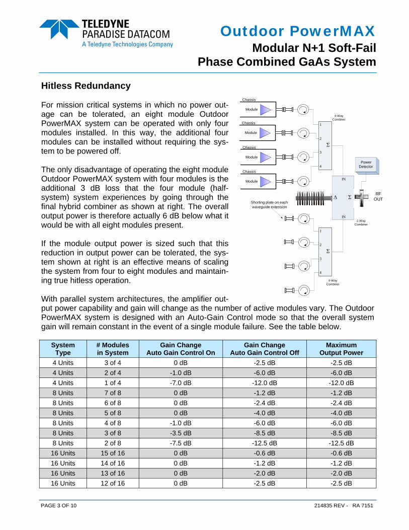
Hitless Redundancy For mission critical systems in which no power out-age can be tolerated, an eight module Outdoor PowerMAX system can be operated with only four modules installed. In this way, the additional four modules can be installed without requiring the sys-tem to be powered off. The only disadvantage of operating the eight module Outdoor PowerMAX system with four modules is the additional 3 dB loss that the four module (half-system) system experiences by going through the final hybrid combiner as shown at right. The overall output power is therefore actually 6 dB below what it would be with all eight modules present. If the module output power is sized such that this reduction in output power can be tolerated, the sys-tem shown at right is an effective means of scaling the system from four to eight modules and maintain-ing true hitless operation. With parallel system architectures, the amplifier out-put power capability and gain will change as the number of active modules vary. The Outdoor PowerMAX system is designed with an Auto-Gain Control mode so that the overall system gain will remain constant in the event of a single module failure. See the table below.
2
Σ
1
3
4
RF OUT
Power Detector
Module
Chassis
Module
Chassis
Module
Chassis
Module
Chassis
2
Σ
1
3
4
Shorting plate on each waveguide extension
ΣΔ
IN
IN
4-Way Combiner
4-Way Combiner
2-Way Combiner
System Type
# Modules in System
Gain Change Auto Gain Control On
Gain Change Auto Gain Control Off
Maximum Output Power
8 Units 7 of 8 0 dB -1.2 dB -1.2 dB 8 Units 6 of 8 0 dB -2.4 dB -2.4 dB 8 Units 5 of 8 0 dB -4.0 dB -4.0 dB 8 Units 4 of 8 -1.0 dB -6.0 dB -6.0 dB 8 Units 3 of 8 -3.5 dB -8.5 dB -8.5 dB 8 Units 2 of 8 -7.5 dB -12.5 dB -12.5 dB 16 Units 15 of 16 0 dB -0.6 dB -0.6 dB 16 Units 14 of 16 0 dB -1.2 dB -1.2 dB 16 Units 13 of 16 0 dB -2.0 dB -2.0 dB 16 Units 12 of 16 0 dB -2.5 dB -2.5 dB
4 Units 3 of 4 0 dB -2.5 dB -2.5 dB 4 Units 2 of 4 -1.0 dB -6.0 dB -6.0 dB 4 Units 1 of 4 -7.0 dB -12.0 dB -12.0 dB
PAGE 4 OF 10 214835 REV - RA 7151
Outdoor PowerMAX Modular N+1 Soft-Fail
Phase Combined GaAs System
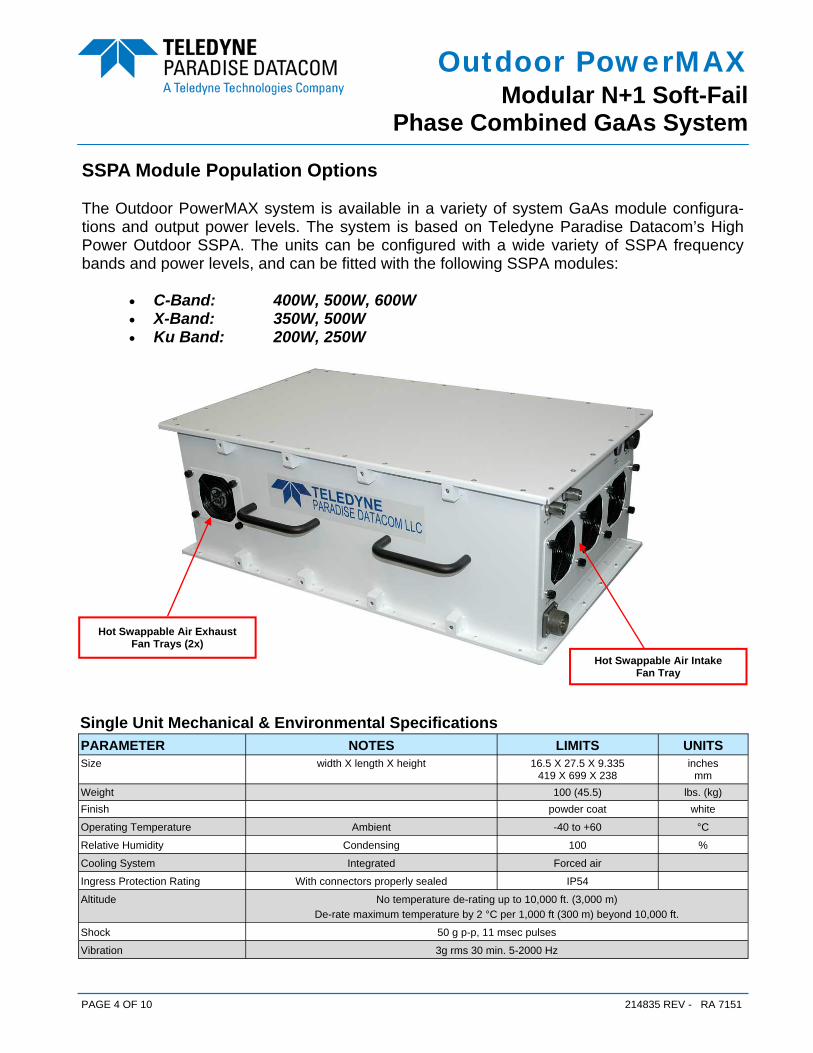
SSPA Module Population Options The Outdoor PowerMAX system is available in a variety of system GaAs module configura-tions and output power levels. The system is based on Teledyne Paradise Datacom’s High Power Outdoor SSPA. The units can be configured with a wide variety of SSPA frequency bands and power levels, and can be fitted with the following SSPA modules:
• C-Band: 400W, 500W, 600W • X-Band: 350W, 500W • Ku Band: 200W, 250W
Hot Swappable Air Intake Fan Tray
Hot Swappable Air Exhaust Fan Trays (2x)
Single Unit Mechanical & Environmental Specifications PARAMETER NOTES LIMITS UNITS Size width X length X height 16.5 X 27.5 X 9.335
419 X 699 X 238 inches
mm Weight 100 (45.5) lbs. (kg) Finish powder coat white
Operating Temperature Ambient -40 to +60 °C Relative Humidity Condensing 100 %
Cooling System Integrated Forced air
Ingress Protection Rating With connectors properly sealed IP54
Altitude No temperature de-rating up to 10,000 ft. (3,000 m) De-rate maximum temperature by 2 °C per 1,000 ft (300 m) beyond 10,000 ft.
Shock 50 g p-p, 11 msec pulses
Vibration 3g rms 30 min. 5-2000 Hz
PAGE 5 OF 10 214835 REV - RA 7151
Outdoor PowerMAX Modular N+1 Soft-Fail
Phase Combined GaAs System
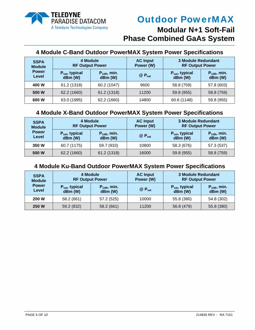
4 Module C-Band Outdoor PowerMAX System Power Specifications SSPA
Module Power Level
4 Module RF Output Power
AC Input Power (W)
3 Module Redundant RF Output Power
Psat, typical dBm (W)
P1dB, min. dBm (W) @ Psat
Psat, typical dBm (W)
P1dB, min. dBm (W)
400 W 61.2 (1318) 60.2 (1047) 9600 58.8 (759) 57.8 (603)
500 W 62.2 (1660) 61.2 (1318) 11200 59.8 (955) 58.8 (759)
600 W 63.0 (1995) 62.2 (1660) 14800 60.6 (1148) 59.8 (955)
4 Module X-Band Outdoor PowerMAX System Power Specifications SSPA
Module Power Level
4 Module RF Output Power
AC Input Power (W)
3 Module Redundant RF Output Power
Psat, typical dBm (W)
P1dB, min. dBm (W) @ Psat
Psat, typical dBm (W)
P1dB, min. dBm (W)
350 W 60.7 (1175) 59.7 (933) 10800 58.3 (676) 57.3 (537)
500 W 62.2 (1660) 61.2 (1318) 16000 59.8 (955) 58.8 (759)
4 Module Ku-Band Outdoor PowerMAX System Power Specifications SSPA
Module Power Level
4 Module RF Output Power
AC Input Power (W)
3 Module Redundant RF Output Power
Psat, typical dBm (W)
P1dB, min. dBm (W) @ Psat
Psat, typical dBm (W)
P1dB, min. dBm (W)
200 W 58.2 (661) 57.2 (525) 10000 55.8 (380) 54.8 (302)
250 W 59.2 (832) 58.2 (661) 11200 56.8 (479) 55.8 (380)

PAGE 6 OF 10 214835 REV - RA 7151
Outdoor PowerMAX Modular N+1 Soft-Fail
Phase Combined GaAs System
8 Module C-Band Outdoor PowerMAX System Power Specifications SSPA
Module Power Level
8 Module RF Output Power
AC Input Power (W)
7 Module Redundant RF Output Power
Psat, typical dBm (W)
P1dB, min. dBm (W) @ Psat
Psat, typical dBm (W)
P1dB, min. dBm (W)
400 W 64.0 (2512) 63.0 (1995) 19200 62.8 (1905) 61.8 (1514)
500 W 65.0 (3162) 64.0 (2512) 22400 63.8 (2399) 62.8 (1905)
600 W 66.0 (3981) 65.0 (3162) 29600 65.0 (3162) 64.0 (2512)
8 Module X-Band Outdoor PowerMAX System Power Specifications SSPA
Module Power Level
8 Module RF Output Power
AC Input Power (W)
7 Module Redundant RF Output Power
Psat, typical dBm (W)
P1dB, min. dBm (W) @ Psat
Psat, typical dBm (W)
P1dB, min. dBm (W)
350 W 63.5 (2239) 62.5 (1778) 21600 62.3 (1698) 61.3 (1349)
500 W 65.0 (3162) 64.0 (2512) 32000 63.8 (2399) 62.8 (1905)
8 Module Ku-Band Outdoor PowerMAX System Power Specifications SSPA
Module Power Level
8 Module RF Output Power
AC Input Power (W)
7 Module Redundant RF Output Power
Psat, typical dBm (W)
P1dB, min. dBm (W) @ Psat
Psat, typical dBm (W)
P1dB, min. dBm (W)
200 W 61.0 (1259) 60.0 (1000) 20000 59.8 (955) 58.8 (759)
250 W 62.0 (1585) 61.0 (1259) 22400 60.8 (1202) 59.8 (955)

PAGE 7 OF 10 214835 REV - RA 7151
Outdoor PowerMAX Modular N+1 Soft-Fail
Phase Combined GaAs System
16 Module C-Band Outdoor PowerMAX System Power Specifications SSPA
Module Power Level
16 Module RF Output Power
AC Input Power (W)
15 Module Redundant RF Output Power
Psat, typical dBm (W)
P1dB, min. dBm (W) @ Psat
Psat, typical dBm (W)
P1dB, min. dBm (W)
400 W 66.7 (4677) 65.7 (3715) 38400 66.1 (4074) 65.1 (3236)
500 W 67.7 (5888) 66.7 (4677) 44800 67.1 (5129) 66.1 (4074)
600 W 68.5 (7079) 67.7 (5888) 59200 67.9 (6166) 67.1 (5129)
16 Module X-Band Outdoor PowerMAX System Power Specifications SSPA
Module Power Level
16 Module RF Output Power
AC Input Power (W)
15 Module Redundant RF Output Power
Psat, typical dBm (W)
P1dB, min. dBm (W) @ Psat
Psat, typical dBm (W)
P1dB, min. dBm (W)
350 W 66.2 (4169) 65.2 (3311) 43200 65.6 (3631) 64.6 (2884)
500 W 67.7 (5888) 66.7 (4677) 64000 67.1 (5129) 66.1 (4074)
16 Module Ku-Band Outdoor PowerMAX System Power Specifications SSPA
Module Power Level
16 Module RF Output Power
AC Input Power (W)
15 Module Redundant RF Output Power
Psat, typical dBm (W)
P1dB, min. dBm (W) @ Psat
Psat, typical dBm (W)
P1dB, min. dBm (W)
200 W 63.7 (2344) 62.7 (1862) 40000 63.1 (2042) 62.1 (1622)
250 W 64.7 (2951) 63.7 (2344) 44800 64.1 (2570) 63.1 (2042)
PAGE 8 OF 10 214835 REV - RA 7151
Outdoor PowerMAX Modular N+1 Soft-Fail
Phase Combined GaAs System
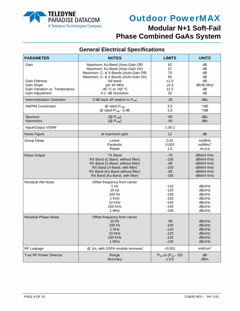
General Electrical Specifications PARAMETER NOTES LIMITS UNITS Gain Gain Flatness Gain Slope Gain Variation vs. Temperature Gain Adjustment
Maximum, Ku-Band (Auto-Gain Off) Maximum, Ku-Band (Auto-Gain On)
Maximum, C- & X-Bands (Auto-Gain Off) Maximum, C- & X-Bands (Auto-Gain On)
full band per 40 MHz
-40 °C to +60 °C 0.1 dB resolution
62 57 70 65
±1.0 +0.3 ±1.5 20
dB dB dB dB dB
dB/40 MHz dB dB
Intermodulation Distortion 3 dB back off relative to P1dB -25 dBc
AM/PM Conversion @ rated P1dB @ rated P1dB - 3 dB
3.5 1.0
°/dB °/dB
Spurious Harmonics
(@ P1dB) (@ P1dB)
-65 -50
dBc dBc
Input/Output VSWR 1.30:1
Noise Figure at maximum gain 12 dB
Group Delay Linear Parabolic
Ripple
0.01 0.003 1.0
ns/MHz ns/MHz2 ns p-p
Noise Output TX Band RX Band (C-Band, without filter) RX Band (X-Band, without filter)
RX Band (X-Band, with filter) RX Band (Ku-Band without filter) RX Band (Ku-Band, with filter)
-75 -155 -85
-155 -85
-155
dBW/4 KHz dBW/4 KHz dBW/4 KHz dBW/4 KHz dBW/4 KHz dBW/4 KHz
Residual AM Noise Offset frequency from carrier 1 Hz
10 Hz 100 Hz 1 KHz
10 KHz 100 KHz 1 MHz
-110 -120 -130 -135 -140 -140 -140
dBc/Hz dBc/Hz dBc/Hz dBc/Hz dBc/Hz dBc/Hz dBc/Hz
Residual Phase Noise Offset frequency from carrier 10 Hz 100 Hz 1 KHz
10 KHz 100 KHz 1 MHz
-90
-100 -110 -120 -125 -130
dBc/Hz dBc/Hz dBc/Hz dBc/Hz dBc/Hz dBc/Hz
RF Leakage @ 1m, with SSPA module removed <0.001 mW/cm2
True RF Power Detector Range Accuracy
Psat to (Psat - 20) ± 0.5
dB dBm
PAGE 9 OF 10 214835 REV - RA 7151
Outdoor PowerMAX Modular N+1 Soft-Fail
Phase Combined GaAs System
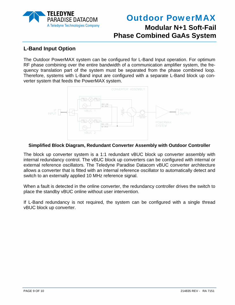
L-Band Input Option The Outdoor PowerMAX system can be configured for L-Band Input operation. For optimum RF phase combining over the entire bandwidth of a communication amplifier system, the fre-quency translation part of the system must be separated from the phase combined loop. Therefore, systems with L-Band input are configured with a separate L-Band block up con-verter system that feeds the PowerMAX system.
The block up converter system is a 1:1 redundant vBUC block up converter assembly with internal redundancy control. The vBUC block up converters can be configured with internal or external reference oscillators. The Teledyne Paradise Datacom vBUC converter architecture allows a converter that is fitted with an internal reference oscillator to automatically detect and switch to an externally applied 10 MHz reference signal. When a fault is detected in the online converter, the redundancy controller drives the switch to place the standby vBUC online without user intervention. If L-Band redundancy is not required, the system can be configured with a single thread vBUC block up converter.
Simplified Block Diagram, Redundant Converter Assembly with Outdoor Controller
PAGE 10 OF 10 214835 REV - RA 7151
Outdoor PowerMAX Modular N+1 Soft-Fail
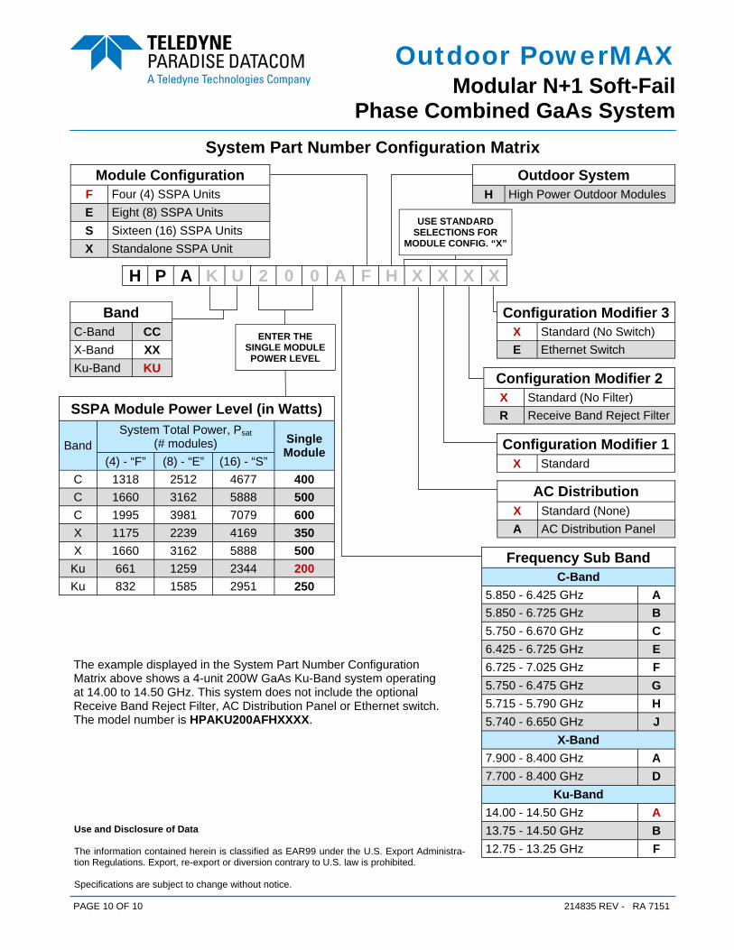
Phase Combined GaAs System System Part Number Configuration Matrix
H P A K U 2 0 0 A F H X X X X
Module Configuration
E Eight (8) SSPA Units S Sixteen (16) SSPA Units
F Four (4) SSPA Units
X Standalone SSPA Unit
SSPA Module Power Level (in Watts)
Band System Total Power, Psat
(# modules) Single Module
(4) - “F” (8) - “E” (16) - “S” C 1318 2512 4677 400 C 1660 3162 5888 500 C 1995 3981 7079 600 X 1175 2239 4169 350 X 1660 3162 5888 500 Ku 661 1259 2344 200 Ku 832 1585 2951 250
Configuration Modifier 1 X Standard
ENTER THE SINGLE MODULE POWER LEVEL
Band C-Band CC X-Band XX Ku-Band KU
Frequency Sub Band C-Band
5.850 - 6.425 GHz A 5.850 - 6.725 GHz B 5.750 - 6.670 GHz C 6.425 - 6.725 GHz E 6.725 - 7.025 GHz F 5.750 - 6.475 GHz G 5.715 - 5.790 GHz H 5.740 - 6.650 GHz J
X-Band 7.900 - 8.400 GHz A 7.700 - 8.400 GHz D
Ku-Band 14.00 - 14.50 GHz A 13.75 - 14.50 GHz B 12.75 - 13.25 GHz F
Use and Disclosure of Data The information contained herein is classified as EAR99 under the U.S. Export Administra-tion Regulations. Export, re-export or diversion contrary to U.S. law is prohibited. Specifications are subject to change without notice.
The example displayed in the System Part Number Configuration Matrix above shows a 4-unit 200W GaAs Ku-Band system operating at 14.00 to 14.50 GHz. This system does not include the optional Receive Band Reject Filter, AC Distribution Panel or Ethernet switch. The model number is HPAKU200AFHXXXX.
Outdoor System H High Power Outdoor Modules
Configuration Modifier 3 X Standard (No Switch) E Ethernet Switch
Configuration Modifier 2 X Standard (No Filter) R Receive Band Reject Filter
AC Distribution X Standard (None) A AC Distribution Panel
USE STANDARD SELECTIONS FOR
MODULE CONFIG. “X”