oscillatory dissipative conjugate heat and mass transfer ...usir.salford.ac.uk/43831/1/imeche j...
TRANSCRIPT

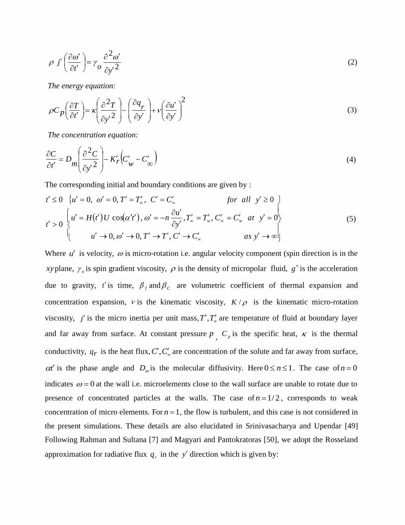
Oscillatory dissipative conjugate heat and mass transfer in chemicallyreacting
micropolar flow with wall couple stress : a finite element numerical study
Shamshuddin, MD, Sheri, SR and Beg, OA
http://dx.doi.org/10.1177/0954408917743372
Title Oscillatory dissipative conjugate heat and mass transfer in chemicallyreacting micropolar flow with wall couple stress : a finite element numerical study
Authors Shamshuddin, MD, Sheri, SR and Beg, OA
Type Article
URL This version is available at: http://usir.salford.ac.uk/43831/
Published Date 2017
USIR is a digital collection of the research output of the University of Salford. Where copyright permits, full text material held in the repository is made freely available online and can be read, downloaded and copied for noncommercial private study or research purposes. Please check the manuscript for any further copyright restrictions.
For more information, including our policy and submission procedure, pleasecontact the Repository Team at: [email protected].

PROC. IMECHE-PART E-
JOURNAL OF PROCESS MECHANICAL ENGINEERING
eISSN: 20413009 | ISSN: 09544089
Impact Factor: 1.448
PUBLISHER: SAGE PUBLISHING
Accepted September 20th 2017
OSCILLATORY DISSIPATIVE CONJUGATE HEAT AND MASS TRANSFER IN CHEMICALLY-REACTING
MICROPOLAR FLOW WITH WALL COUPLE STRESS: FINITE ELEMENT NUMERICAL STUDY
Shamshuddin MD 1*
, Siva Reddy Sheri2 and O. Anwar Bég
3
1*Department of Mathematics, Vaagdevi College of Engineering, Warangal, Telangana, India. 2Department of Mathematics, GITAM University, Hyderabad Campus, Telangana, India.
3Fluid Mechanics and Propulsion, Aeronautical and Mechanical Engineering, University of Salford,
Newton Building, The Crescent, Salford, M54WT, England, UK.
*Corresponding author: [email protected]
Abstract
High temperature non-Newtonian materials processing provides a stimulating area for process
engineering simulation. Motivated by emerging applications in this area, the present article
investigates the time-dependent free convective flow of a chemically-reacting micropolar fluid
from a vertical plate oscillating in its own plane adjacent to a porous medium. Thermal
radiative, viscous dissipation and wall couple stress effects are included. The Rosseland diffusion
approximation is used to model uni-directional radiative heat flux in the energy equation.
Darcy’s model is adopted to mimic porous medium drag force effects. The governing two-
dimensional conservation equations are normalized with appropriate variables and transformed
into a dimensionless, coupled, nonlinear system of partial differential equations under the
assumption of low Reynolds number. The governing boundary value problem is then solved
under physically viable boundary conditions numerically with a finite element method based on
the weighted residual approach. Graphical illustrations for velocity, micro-rotation (angular
velocity), temperature and concentration are obtained as functions of the emerging physical
parameters i.e. thermal radiation, viscous dissipation, first order chemical reaction parameter etc.
Furthermore, friction factor (skin friction), surface heat transfer and mass transfer rates have
been tabulated quantitatively for selected thermo-physical parameters. A comparison with
previously published paper is made to check the validity and accuracy of the present finite
element solutions under some limiting cases and excellent agreement is attained. Additionally, a
mesh independence study is conducted. The model is relevant to reactive polymeric materials
processing simulation.
Keywords Wall couple stress, Thermal Radiation, Chemical reaction, Micropolar fluid, FEM,
Materials processing, Buoyancy.

1. INTRODUCTION
In recent years, non-Newtonian fluids have received significance interest, since they offer a more
accurate framework for simulating the characteristics of a fluid with suspended particles than the
classical Navier-Stokes (Newtonian) viscous model. Such fluids abound in complex industrial
processes for example, in slurry and petro-chemical materials processing. Micro-structural fluids
require additional balance equations corresponding to angular momentum. Eringen [1] proposed
the theory of micropolar fluids (a simplification of his more complex micromorphic fluid model)
by developing constitute equations that take into account the effects arising from the local
structure and micro-motions of the micro elements. Also micropolar fluids can support the shear
stress, couple stress, body couples and exhibit gyratory motions. By generalizing of micropolar
fluids to heat conduction and other thermal effects, Eringen [2] developed a robust theory of
thermo-micropolar fluids. These theories present an excellent mechanism for exploring new non-
Newtonian characteristics and simultaneously validating solutions to mathematical models.
Interesting aspects of theory and applications of micropolar fluids can be found in books by
Eringen [3] and Lukaswiascz [4]. Further details of applications in petro-chemical and process
engineering are provided in the lucid review article of Airman et al. [5]. These investigations
have addressed numerous multi-physical phenomena including thermal dispersion, thermal
radiation, electrophoresis, wavy surfaces, body rotations, oscillatory flow, squeezing
hydrodynamics, fluid dynamic stability and magnetohydrodynamics. The multi-scale, multi-
physical nature of materials processing systems therefore provides a rich arena for exploring
micropolar transport phenomena. Recent investigations of micropolar materials processing
include Gupta et al. [6] who used a variational finite element method to investigate free and
forced convection of micropolar liquids in contracting sheet flow under strong radiative flux.
Rahman and Sultana [7] analyzed the radiative heat transfer effects on micropolar flow with
variable heat flux in a porous medium was examined by Considering the effects of MHD and
radiation Reddy [8] investigated unsteady convection flow of micropolar fluid past a vertical
porous plate with variable wall heat flux. Zueco et al. [9] used network electro-thermal
simulation to analyze buoyancy-driven magnetic micropolar convection flows in vertical
conduits containing complex porous materials.

Conjugate heat and mass transfer problems have also stimulated considerable interest. Both
numerical and analytical studies have ben communicated in this regard. This category of flow
occurs as a result of combined buoyancy effects of thermal diffusion and diffusion through
chemical species, which find important applications in industrial materials fabrication and
chemical engineering. These include food drying, foodstuff processing and polymer production.
The term conjugate heat transfer describes the interaction between the convective fluid and heat
conduction through the bounding wall. The heat transfer coefficient or thermal boundary
conditions become an integral part of solving such problems which deviate from the
conventional boundary layer flow analysis, in which they are usually specified. This condition is
necessary in the heat transfer analysis of extended surfaces where the thermal boundary
conditions are specified only at the ends of the surfaces. It may be noted that
conjugate/convective thermal boundary conditions are known arise in many diverse areas of
technology including combustion in gas turbines, convective flows setup where the bounding
surfaces absorb heat by solar radiation, design of efficient heat exchangers, optimization of
turbine blade cooling system etc. An important analysis in this regard was presented by Aziz [10]
who considered convective surface boundary conditions. This in turn has stimulated a number of
investigations in boundary layer flows with convective surface boundary conditions for different
physical scenarios. By employing finite difference schemes, Pop and Merkin [11, 12] studied
conjugate heat transfer from a vertical plate in a saturated permeable medium. Conjugate forced
convection heat transfer from a continuous and moving flat sheet was analyzed by Char et al.,
[13] employing a cubic spline collocation numerical method. Recently Khalid et al. [14]
presented exact solutions (using a Laplace transform method) for conjugate heat and mass
transfer in transient micropolar flow with wall couple stress. This has partly motivated the
current investigation in which we extend the analysis in [14] to consider thermal radiation,
viscous dissipation and first order chemical reaction effects, all of which may feature in realistic
materials and process flow systems. Furthermore, detailed reviews of other investigations into
conjugate heat transfer are provided by Chaudhary and Jain [15], Hussain [16], Zhang [17] and
Bejan [18]. In recent years, conjugate natural convection flows with radiative heat transfer have
mobilized some interest owing their significance in high-temperature engineering systems such
as heat exchangers, combustion chambers and materials synthesis. These flows require a more
sophisticated approach to radiative heat transfer in the system which can substantially influence

performance and modify characteristics of manufactured products. In addition to this, such
regimes are strongly influenced by thermal boundary conditions. Arpaci [19] conducted seminal
work on analyzing thermal radiation effects in laminar free convection from a heated vertical
plate. England and Emery [20] computed the impact of thermal radiation of an optically-thin
gray gas on the laminar free convection flow past a stationary vertical plate. Thereafter many
researchers further studied thermal radiation problems in fluid dynamics including Özisik [21]
who considered the interaction of thermal radiation transfer with both thermal conduction and
convection. Bestman and Adjepong [22] presented an analysis on unsteady hydromagnetic free
convection flow with radiative heat transfer in a rotating fluid. Other studies of relevance include
convection-radiation flow along a vertical wavy surface as examined by Molla and Hossain [23].
Jang et al. [24] studied flows in rotating horizontal rectangular ducts with radiation effects. Jang
et al. [25] further investigated radiative flows in stationary rectangular ducts. Free convective
transport along an inclined flat plate with temperature-dependent viscosity was studied by
Siddiqa et al. [26]. Siddiqa and Hossain [27] investigated mixed convection with radiative flux
effects. In the context of micropolar flows, several researchers have also examined thermal
radiative heat transfer. Abo-Eldahab and Ghonaim [28] evaluated radiation effects on heat
transfer of a micropolar fluid through a porous medium. Olajuwon and Oahimire [29] obtained
perturbation solutions for the double-diffusive convection in time-dependent radiative
hydromagnetic micropolar convection. Kundu et al. [30] studied thermo-diffusive and radiative
effects on rotating micropolar convection flows.
In the most of the above investigations, viscous heating has generally been neglected on the
premise that under normal conditions the Eckert number is small based on an order of magnitude
analysis. The viscous dissipation effect however can have a significant influence in materials
processing operations, in particular those associated with rheological (non-Newtonian)
processes, as elaborated by Warren [31]. Chen [32] described the effects of heat and mass
transfer in MHD free convection with Ohmic heating and viscous dissipation. Gnaneswara and
Bhaskar [33] investigated the radiation and mass transfer effects on transient magneto-
convection with viscous dissipation.
In numerous process engineering systems, chemical reactions take place. These can markedly
modify heat and mass transfer rates. Most analytical studies consider first order chemical
reaction effects and assume the reaction to be destructive. Recently Srinivasacharya and Upender

[34] have considered the composite effects of thermal radiation and chemical reaction on
magnetic free convection heat and mass transfer in micropolar fluids. Sheri and Shamshuddin
MD [35] have addressed the problem of coupled heat and mass transfer in
magnetohydrodynamic micropolar flow with both viscous dissipation and chemical reaction
effects. Sheri and Shamshuddin [36] have further presented finite element numerical solutions
for diffuso-thermal and chemical reaction effects on transient free convection micropolar flow.
Further studies of reactive micropolar flows include Rawat et al. [37] (which considered double
diffusive convection in reactive micropolar flow from an extending sheet) and Pal and Talukdar
[38].
The presence of oscillatory flow in materials fabrication processes is also of great importance.
This invokes time-dependent effects and these can dramatically modify momentum, heat and
species diffusion characteristics, as elaborated by Reis [39]. Many insightful investigations have
been reported concerning oscillatory transport phenomena. These include Pan and Li [40],
Adesanya et al. [41], Bhargava et al. [42] (who used finite element methods and considered
cross-diffusion), Adesanya [43] who considered momentum slip effects at the wall and Rajesh et
al. [44] who considered hydromagnetic enrobing flow over a curved geometry with reactive and
thermal oscillation behavior. Further studies include Adesanya et al. [45] who considered
viscous heating in pulsatile porous media pumping, Maqbool et al. [46] who presented Fourier
solutions to a family of oscillatory non-Newtonian ferromagnetic gel flows, Adesanya et al. [47]
who considered transient boundary conditions in magnetic heat transfer and Bég et al. [48] who
developed network electro-thermal solutions for oscillatory heat transfer of magnetized polymers
in a spinning channel.
The above oscillatory studies all confirmed the considerable impact that oscillation frequency
exerts on shear stress, wall heat transfer rates and in some cases [46] also on vorticity fields.
However they did not consider species diffusion or the micropolar model. In the present
problem, therefore, we extended the analytical work of Khalid et al. [14] by taking into account
of thermal radiation, viscous dissipation and first order chemical reaction effects and deriving
finite element numerical solutions for generalized micropolar radiative-convection flow from a
vertical surface in a porous medium. The closed-form exponential solutions presented by Khalid
et al. [14] provide a benchmark for the current computational solutions. The effects of various
emerging thermo-physical parameters on the velocity, micro-rotation velocity, temperature and

concentration profiles as well as on local skin friction coefficient and wall couple stress are
visualized and tabulated. Furthermore, a mesh-independence study is also conducted. The current
problem, to the best knowledge of the authors, has not been communicated thusfar in the
technical literature.
2. MATHEMATICAL MODEL
Consider the unsteady, laminar incompressible, free convective heat and mass transfer flow of
micropolar fluid from an infinite porous oscillating vertical plate adjacent to a porous medium.
Thermal radiation, viscous dissipation and chemical reaction effects are included. The coordinate
system is such that the x axis is taken along the plate and y axis is taken perpendicular to the
plate. The micropolar fluid saturates the porous half space 0y . The schematic model of the
coordinate system and physical model is represented in Figure 1. Initially at the time 0t , both
the fluid and the plate are at rest with constant temperature T and constant concentration
C . At
time 0t the plate is given sudden impulse, and the motion is induced against gravity such that
plate begins to oscillate in its own plane with velocity itCostHUV .Here tH is the
Heaviside (unit step) function, U is the amplitude of the motion, i
is the unit vector in the
vertical flow direction and is the frequency of oscillation. The temperature wT and
concentration wC of the plate are raised linearly with respect to time and thereafter maintained as
constant. It is assumed that the plate is infinite in extent and hence all physical quantities depend
on y and t only. By virtue of these assumptions the governing equations for unsteady natural
convective flow under Boussinesq’s approximations may be formulated as follows, by extending
the model of Khalid et al. [14] to include the radiative flux and porous media terms in Rahman
and Sultana [7], the viscous dissipation term in the model of Zueco et al. [9] and Reddy et al.
[33] and the chemical reaction term in the model of Srinivasacharya and Upender [34] we arrive
at the new generalized model:
The linear momentum equation:
y
KC
wC
CgT
wT
fg
y
uK
t
u
2
2 (1)
The angular momentum equation:
2
2
yot
j
(2)
The energy equation:
2
2
2
y
u
y
rq
y
T
t
TpC (3)
The concentration equation:
C
wCrK
y
C
mD
t
C
2
2 (4)
The corresponding initial and boundary conditions are given by :
yasCCTTu
yatCCTTy
untUtHu
t
yallforCCTTut
ww
,,0,0
0,,,cos0
0,,0,00
(5)
Where u is velocity, is micro-rotation i.e. angular velocity component (spin direction is in the
xy plane, o is spin gradient viscosity, is the density of micropolar fluid,
g is the acceleration
due to gravity, t is time, f and C are volumetric coefficient of thermal expansion and
concentration expansion, is the kinematic viscosity, /K is the kinematic micro-rotation
viscosity, j is the micro inertia per unit mass, TT , are temperature of fluid at boundary layer
and far away from surface. At constant pressure p , pC is the specific heat, is the thermal
conductivity, rq is the heat flux, CC , are concentration of the solute and far away from surface,
t is the phase angle and mD is the molecular diffusivity. Here 10 n . The case of 0n
indicates 0 at the wall i.e. microelements close to the wall surface are unable to rotate due to
presence of concentrated particles at the walls. The case of 2/1n , corresponds to weak
concentration of micro elements. For 1n , the flow is turbulent, and this case is not considered in
the present simulations. These details are also elucidated in Srinivasacharya and Upendar [49]
Following Rahman and Sultana [7] and Magyari and Pantokratoras [50], we adopt the Rosseland
approximation for radiative flux rq in the y direction which is given by:

y
T
krq
4
3
4 (6)
Here and k are the Stefan-Boltzmann constant and mean absorption coefficient respectively.
Hence the fluid medium is assumed optically-thick for the present analysis. Eqn. (6) results in a
highly nonlinear energy equation inT and it is difficult to obtain a solution. However, researchers
have resolved this problem by assuming small temperature differences with in the fluid flow (see
[51]-[53]). In this situation, Rosseland’s model can be linearized about ambient temperature T
assuming that the difference in the temperature with in the flow such that 4T can be expressed as
linear combination of the temperature. Using Taylor’s series expansion about T the expansion
of 4T can be written as follows, neglecting higher order terms:
43344
TTTT (7)
Differentiating equation (6) w.r.t y and using (7), we obtain:
2
2
3
316
y
T
k
T
y
rq
(8)
Now simply replacing 3T in Eq. (6) with 3
T , Eq. (3) can be expressed as follows:
23
3
161
2
2
y
uT
kt
TpC
y
T
(9)
In order to write the governing equations and boundary conditions in dimensionless form, the
following non-dimensional quantities are introduced:
jU
JU
Cw
C
CC
Tw
T
TT
Ut
Uty
Uy
U
uu
2
2,
2
,,,2
,2
,,
(10)
Here U represents scale of free stream velocity. Furthermore, the spin gradient viscosity o
which connects the coefficient of viscosity and micro-inertia is defined as follows:
whereJJ
o 21
2 (11)

Here denotes the dimensionless viscosity ratio parameter or microrotation parameter, in which
is the coefficient of gyro-viscosity (Eringen’s vortex viscosity) and J is the dimensionless
micro inertia coefficient. By introducing the non-dimensional quantities in eqns. (10), (11), eqns.
(1)-(4) reduce to the following dimensionless form :
ymG
rG
y
u
t
u
2
21 (12)
2
21
yt
(13)
2
2
21
Pr
1
y
uEc
yN
t
(14)
2
21
ySct (15)
Where
2
2
o
jdenotes dimensionless spin gradient viscosity parameter,
3
U
TT
wTg
rG
denotes the Grashof number,
3U
CC
wCg
mG
is the species (solutal)
Grashof number,
p
C
rP is the Prandtl number,
mD
cS
denotes Schmidt number,
Tw
TpC
UEc
2
is the Eckert (viscous heating) number, kk
TN
3
316
is radiative-conduction
parameter and 2
U
rK
is the chemical reaction parameter. The boundary conditions (5) are
then given by the following dimensionless equations

yasu
yaty
unttHu
t
yallforCCTTut
0,0,0,0
0,1,1,,cos0
0,,0,00
(16)
3. NUMERICAL SOLUTIONS WITH FINITE ELEMENT METHOD (FEM)
The finite element method (FEM) is employed to solve the transformed, coupled boundary value
problem defined by eqns. (12)-(15) under (16). FEM is the most versatile technique available for
engineering analysis and equally adept at handling ordinary or partial differential equations as
well as integral equations. The general details of the variational finite element method are
documented succinctly in Reddy [54] and Bathe [55]. FEM has been applied to study many
complex boundary value problems in micropolar fluid mechanics, many of which are considered
in Bég et al. [56]. Micropolar heat and mass transfer applications also include [57]-[59].The
fundamental steps involved in the finite-element analysis of a problem are as follows:
Discretization of the infinite fluid domain into finite elements
Derivation of element equations
Assembly of Element Equations
Imposition of boundary conditions
Solution of assembled equations
The final matrix equation obtained can be solved by any efficient iterative scheme.
3.1 Variational formulation
The variational formulation associated with Eqns. (12) - (15) over a typical two-node linear
element 1, ee yy is given by:
0)(1
22
2
11
dyy
AGmGry
uA
t
uw
e
e
y
y
(17)

01
2
2
32
dyy
At
we
e
y
y
(18)
01
2
2
2
43
dyy
uEc
yA
tw
e
e
y
y
(19)
011
2
2
4
dyySct
we
e
y
y
(20)
Here ,1w ,2w 3w and 4w are arbitrary test functions and may be viewed as the variations in ,u
, and respectively and 11A , 2A ,
1
3A , NA 1Pr
1
4 . After dropping the
order of integration and non-linearity, we arrive at the following system of equations.
0)(
11
11211
1
11
e
e
e
e
y
y
y
yy
uwdy
ywAGmwwGr
y
u
y
wA
t
uw
(21)
0
11
2
2
32
e
e
e
e
y
y
y
yy
wdyyy
wA
tw
(22)
0
11
33
3
43
e
e
e
e
y
y
y
yy
wdyy
u
y
uwEc
yy
wA
tw
(23)
0)(1
11
4
4
4
4
e
e
e
e
y
y
y
yySc
wdyw
yy
w
Sctw
(24)
3.2 Finite Element formulation
The finite element model may be obtained from Eqs. (21) - (24) by substituting finite element
approximations of the form:
,2
1
j
e
j
e
juu ,2
1
j
e
j
e
j
2
1j
e
j
e
j and
2
1j
e
j
e
j (25)
With ),2,1(4321 iwwww e
j where ,e
ju ande
j
e
j , e
j are the velocity in the
direction of x-axis, y-axis and temperature respectively at the thj node of typical
the element
1, ee yy and e
i are the shape functions for this element 1, ee yy and are taken as:

andyy
yy
ee
ee
1
1
1 ,1
2
ee
ee
yy
yy
1 ee yyy
(26)
The finite element model of the equations for the the element thus formed is given by.
e
e
e
e
e
e
e
e
e
e
e
e
b
b
b
bU
MMMM
MMMM
MMMM
MMMMU
KKKK
KKKK
KKKK
KKKK
4
3
2
1
44434241
34333231
24232221
14131211
44434241
34333231
24232221
14131211
(27)
Where mnmn MK , and meeeeeeeee banduu ,,,,,,,
,1,( nm )4,3,2, are the set of matrices of order 22 and 12 respectively and )(prime
indicatesdy
d . These matrices are defined as follows:
,0,
,,
,,
14131211
1413
2
12
1
11
1
11
11
ijijij
z
z
e
j
e
iij
y
y
e
j
e
iij
y
y
e
j
e
iij
y
y
e
je
iij
y
y
e
je
i
ij
MMMdyM
dyGmKdyGrK
dyy
AKdyyy
AK
e
e
e
e
e
e
e
e
e
e
(28)
,0,,0
,0,,0,0
24232221
24
3
232221
1
1
ij
z
z
e
j
e
iijijij
ij
y
y
e
je
i
ijijij
MdyMMM
Kdyyy
AKKK
e
e
e
e
(29)
0,,0,0
,0,,,0
34333231
3433
4
3231
1
11
ij
y
y
e
j
e
iijijij
ij
y
y
e
je
iij
z
z
e
je
i
ijij
MdyMMM
Kdyyy
uEcKdy
yyAKK
e
e
e
e
e
e
(30)

0,,0,0
,1
,0,0,0
44434241
44434241
1
11
ij
y
y
e
j
e
iijijij
y
y
e
j
e
i
y
y
e
je
i
ijijijij
MdyMMM
dydyyySc
KKKK
e
e
e
e
e
e
(31)
11
11
43
21
,
,,
e
e
e
e
e
e
e
e
y
y
e
i
e
i
y
y
e
i
e
i
y
y
e
i
e
i
y
y
e
i
e
i
yb
yb
yb
y
ub
(32)
In one dimensional space, linear and quadratic elements or higher order can be taken. Here the
entire flow domain is considered by dividing it into successively sized grids of order 81x81,
101x101 and 121x121 in the y-axis direction. After many tests a grid size with 101 intervals has
been adopted. Thus all the computations are executed with 101 intervals of equal step size 0.01.
At each node, 4 functions are to be evaluated and after assembly of the element equations, a set
of 404 non-linear equations are obtained which necessitate an iterative solution subject to the
specified boundary conditions. The iterative process is terminated when the following condition
is met: 6
,
1 10 ji
nn where ,,,U and n denote the iterative step. In order to see
the effects of step size (h) the finite element code is run with step sizes as h=0.01 and very good
agreement is obtained for different profiles. Hence, this method has been proven to be adequate
and gives accurate results for the conservation equations. It is also important to compute
engineering quantities of primary interest, which are the skin-friction, wall couple stress (surface
micro-rotation gradient), Nusselt number and Sherwood number.
Skin-friction is obtained as,
0
y
fy
uC (33)
Wall couple stress is defined as,
0
y
my
C
(34)
The Nusselt number is computed as,

0
Re/
yyxNu
(35)
The Sherwood number is evaluated as,
0Re/
yyxSh
(36)
3.3 Study of Grid Independence
In general, to study the grid independency (or) dependency, we check how the mesh size should
be varied at different mesh (grid) sizes and get a range at which there is no subsequent variation
in the solutions. For this purpose, we have presented numerical values of velocity, temperature
and concentration for different values of mesh sizes at time 2.0t in the Table 1, which shows
that no variations in velocity, angular velocity, temperature and concentration. Hence the results
are independent of mesh size.
4. VALIDATION OF NUMERICAL RESULTS
To verify the accuracy and validity of the numerical results employed by the weighted residual
approach and the Galerkin finite element method, the results have been compared to the
analytical solutions for local skin friction coefficient and wall couple stress coefficient reported
by Khalid et al. [14] for different values of , ,n Pr, ,Gr ,Gm ,Sc ,t and t in Table 2. These
solutions negate thermal radiation, viscous dissipation and homogeneous chemical reaction
effects, since these terms were ignored in the model of Khalid et al. [14]. Generally, very good
correlation is achieved. Table 2 further shows that in the absence of radiative flux, chemical
reaction or viscous heating, skin friction increases as , Pr, ,Sc t increase but decreases with a
rise in ,n ,Gr ,Gm t . Further, it is observed that wall couple stress decreases as , ,n Pr, ,Gr
,Gm ,Sc ,t and t increase.
5. GRAPHICAL RESULTS AND DISCUSSION
In order to gain a clear insight into the physical problem, numerical calculations for distribution
of the velocity, microrotation (angular) velocity, temperature and concentration for different
values of the control parameters are illustrated in Figs. (2) - (27). In order to study the effects of

pertinent parameters in fluid flow explicit computations were carried out by varying micro-
rotation parameter , dimensionless spin gradient viscosity parameter , microelement surface
condition ,n Grashof number ,Gr species Grashof number ,Gm Prandtl number Pr, radiative-
conduction parameter ,N Eckert number ,Ec Schmidt number ,Sc phase angle t and chemical
reaction parameter .
Figures 2-3 illustrate the influence of micro-rotation parameter on velocity and micro-
rotation profiles. It is evident that velocity distribution is greater for a Newtonian fluid ( =0)
with the given parameters, as compared with non-Newtonian fluid (micropolar fluid). Peak
values are attained close to the plate and these migrate away from the plate with increasing .
All profiles decay from the peak to vanish in the free stream velocity. In addition, the micro-
rotation (fig. 3) i.e. angular velocity takes negative values throughout the regime. The lowest
values are at the plate surface and approach zero as one moves away from the plate surface
which agrees with the imposed boundary condition on micro-rotation. Hence micro-rotation
velocity profiles increase as increases.
Figures 4, 5 present the velocity and angular velocity (micro-rotation) profiles for various
values of spin gradient viscosity parameter . It is observed from that velocity increases as spin
gradient viscosity parameter increases whereas micro-rotation is strongly reduced i.e. the
gyratory motion of the micro-elements is decelerated with greater spin gradient viscosity. Drag
in the linear velocity field is however reduced and significant acceleration induced with greater
spin gradient viscosity and indeed this concurs with many other studies in micropolar fluid
mechanics including Hossain and Chowdhury [60].
Figures 6 and 7 depict the effect of microelement surface condition (n) on both velocity and
micro-rotation profiles. Micro element parameter ,n describes the relation between micro-
gyration vector and shear stress. It is observed that the velocity increases with increasing values
of n . Furthermore the momentum boundary layer thickness is decreased with greater n values,
and this is attributable to the smaller micro-gyration vector. The impact of increasing n however
diminishes with greater distance from the plate. Micro-rotation velocity increases as n increases,
although values are always negative. All profiles converge smoothly to zero in the free stream
i.e. the influence of n strongly decreases with progressive distance from the plate.

Figures 8 and 9 shows the variations in velocity and microrotation velocity profiles for
various values of thermal Grashof number,Gr . Gr quantifies the relative magnitude of the
buoyancy force and the opposing frictional (viscous) forces acting on the micropolar fluid.
Physically the positive, negative and zero )00,0.,.( GrandGrGrei values of the Grashof
number represents the cooling, heating of the boundary surface and absence of free convection
currents respectively. The velocity profiles are significantly elevated with an increase in thermal
Grashof number, since buoyancy assists in momentum development. The flow is therefore
strongly accelerated for the case where the plate is cooled (Gr >0). Velocity profiles exhibit a
parabolic distribution, ascending from the plate, achieving a peak value near the plate and then
decaying to vanish in the free stream, far from the plate. Conversely an increase in thermal
Grashof number strongly damps the micro-rotation field i.e. decreases angular velocity of the
micro-elements. Again values are consistently negative indicating a reverse spin in the micro-
elements. As with linear velocity, in the free stream micro-rotation vanishes and is generally
minimized at the plate.
Figures 10, 11 present the response in linear velocity and micro-rotation to a variation in
species (solutal) Grashof number i.e. Gm . This parameter embodies the relative contribution of
species buoyancy force to viscous hydrodynamic force. With increasing Gm, the mass diffusion
effect leads to an acceleration in the flow i.e. increase in velocity values and an associated
decrease in hydrodynamic boundary layer thickness. We note that for the case Gm = 0, species
buoyancy effect vanishes and the momentum eqn. (12) is de-coupled from the species diffusion
(concentration) eqn. (15). Micro-rotation values are significantly reduced with increasing Gm
values i.e. increasing species buoyancy (associated with greater concentration gradient) exerts a
similar influence to increasing thermal buoyancy and strongly damps the angular velocity. The
spin of the micro-elements is therefore markedly inhibited with greater buoyancy effects.
Figures 12-13 illustrate the evolution in linear velocity and micro-rotation distributions with
different values of phase angle t . A weak oscillatory behavior is computed for the linear
velocity and with increasing phase angle (three different values are chosen) there is a progressive
deceleration in the flow. Infact at maximum phase angle, flow reversal is induced since the linear
velocities attain negative values at t = π. At zero phase angle the maximum velocity is
achieved at the plate whereas for t = π, the maximum velocity is attained in the free stream.

Strong damping is therefore generated in the flow with increasing phase angle. Conversely an
increase in phase angle is observed to enhance the micro-rotation i.e. it increases angular
velocity. Greater oscillation of the plate encourages spin of the micro-elements and in all cases
the minimum micro-rotations (maximum negative values) arise at the plate eventually vanishing
in the free stream.
Figures 14-16 illustrate the influence of Prandtl number (Pr) on the linear, angular velocity
(micro-rotation) and temperature profiles. With greater Prandtl number, it is observed in fig. 14,
that the velocity is significantly decreased throughout the boundary layer. Prandtl number
represents the relative rate of momentum diffusion to energy diffusion. For Pr < 1 energy
diffusion rate exceeds momentum diffusion. Also fluids with higher Prandtl number possess
greater viscosities and as Pr increases from 0.3 through 0.5, 0.7 to 0.9, the viscous resistance
leads to depletion in velocity. This will also manifest in an increase in momentum
(hydrodynamic) boundary layer thickness. Similarly there is a strong depression in micro-
rotation (fig. 15) with increasing Prandtl number. The coupling of the linear and angular
momentum equations manifests in an indirect deceleration in the micro-element gyratory
motions (micro-rotation) due to damping of the linear velocity field. Temperature is also
significantly suppressed with greater Prandtl number, as plotted in fig. 16. Greater Prandtl
number corresponds to a lower thermal conductivity. This leads to a reduction in thermal energy
convected through the fluid from the plate (Gr >0 i.e. plate cooling) and also depresses the
thermal boundary layer thickness. These trends have also been computed by numerous other
researchers including Rahman and Sultana [7].
Figures 17-19 present the effect of thermal radiation-conduction parameter ( N ) on
respectively linear velocity, micro-rotation and temperature profiles. This parameter is defined as
kk
TN
3
316
and features in the augmented thermal diffusion term in eqn. (14) i.e. 2
2
1Pr
1
yN
.
It defines the relative contribution of thermal radiation heat transfer to thermal conduction heat
transfer. When N <1 thermal conduction dominates. When N = 1 both thermal conduction and
thermal radiation contributions are equal. For N >1 thermal radiation dominates over thermal
conduction. In the present simulations, we confine attention to the last of these three cases. Fig.
17 clearly reveals that there is a strong deceleration in the linear velocity with increasing N

values. The energizing of the flow enhances thermal diffusion but counteracts momentum
diffusion. This leads to an increase in momentum boundary layer thickness. A similar
observation has been reported by Abo-Eldahab and Ghonaim [28] and Olajuwon and Oahimire
[29]. Conversely increasing N values are found to elevate the micro-rotation of micro-elements
as observed in fig. 18. Increasing radiation-conduction parameter is also found to decrease
temperatures in the boundary layer (fig. 19). Thermal boundary layer thickness is therefore also
reduced with greater values of N.
Figures 20-22 present the effects of the viscous dissipation parameter i.e., the Eckert
number Ec on the velocity, micro-rotation and temperature fields. Eckert number signifies the
quantity of mechanical energy converted via internal friction to thermal energy i.e. heat
dissipation. Increasing Ec values will therefore cause an increase in thermal energy contributing
to the flow and will heat the regime. Positive Eckert number implies cooling of the wall and
therefore a transfer of heat to the micropolar fluid. Convection is enhanced and we observe in
consistency with this that at the fluid is accelerated i.e. linear velocity is elevated (fig. 20).
Similarly there is an enhancement in micro-rotation in the micropolar fluid with increasing Ec
values (fig. 21). Temperatures are markedly increased with greater Eckert number (fig. 22). For
all non-zero values of Ec the temperature overshoot near the wall is distinct, this overshoot
migrates marginally further into the boundary layer with an increase in Ec. Very smooth decays
in temperature profiles are observed for all values of Eckert number and the convergence of
profiles in the free stream indicates that an adequately large infinity boundary condition has been
imposed in the finite element model.
Figures 23-25 illustrate the velocity, micro-rotation and concentration profiles for different
values of Schmidt number, Sc. The Schmidt number embodies the ratio of the momentum to the
mass diffusivity i.e. DvSc / . The Schmidt number therefore quantifies the relative
effectiveness of momentum and mass transport by diffusion in the hydrodynamic (velocity) and
concentration (species) boundary layers. For 1Sc momentum diffusion rate exceeds the
species diffusion rate. The opposite applies for Sc < 1. For Sc =1 both momentum and
concentration (species) boundary layers will have the same thickness and diffusivity rates will be
equal. It is observed that as the Schmidt number increases velocity, angular velocity and
concentration all decrease. The momentum boundary layer thickness is also reduced with greater
Schmidt number. The suppression in micro-rotation is associated with a deceleration in the linear

velocity field. The depression in concentration magnitudes is due to the reduction in molecular
diffusivity which manifests in a stifled migration of species. Concentration boundary layer
thickness is therefore also decreased with increasing Schmidt number.
Figures 26-27 represents the influence of chemical reaction parameter ( ) on the velocity
and concentration profiles. The reaction parameter is based on a first-order irreversible chemical
reaction which takes place both in the bulk of the fluid (homogeneous) as well as at plate which
is assumed to be catalytic to chemical reaction. Although chemical reactions generally fall into
one of two categories i.e. homogenous or heterogenous, the former is of interest in the present
study. Homogenous chemical reactions take place uniformly throughout a given phase and are
similar in nature to an internal source of heat generation. We consider the destructive type of
homogenous chemical reaction. Increasing the chemical reaction parameter produces a
decrease in velocity (fig. 26). The momentum boundary layer thickness is therefore increased
substantially with greater chemical reaction effect. It is noticed that concentration distributions
decrease when the chemical reaction increases. Physically, for a destructive case, chemical
reaction takes place and progressively destroys the original species. This, in turn, suppresses
molecular diffusion of the remaining species which leads to a fall in concentration magnitudes
and a decrease in concentration boundary layer thickness.
Finally fig. 28 illustrates the difference in linear velocity for Newtonian and micropolar
fluids. Strong deceleration is present for the micropolar case. The presence of micro-elements
therefore achieves lower acceleration compared with Newtonian fluids which ignore
microstructural effects.
6. CONCLUSIONS
In this work motivated by applications in materials processing of slurry systems, a mathematical
model has been developed for conjugate free convection heat and mass in transient flow of an
incompressible, micropolar fluid from an oscillating vertical plate in porous media. Viscous
heating, thermal radiation and homogeneous chemical reaction effects have been incorporated
into the model. The conservation equations for momentum, angular momentum (micro-rotation
component), energy and concentration have been non-dimensionlized with appropriate variables.
The resulting non-linear, transient, coupled system of partial differential equations and set of

initial and boundary conditions has been solved numerically, using the variational finite element
method with Galerkin weighted residual scheme. Validation for solution for selected cases has
been conducted with previous published works i.e. Khalid et al. [14] and excellent correlation
achieved. A grid independence study has also been performed. The computations have been
executed in MATLAB software, and have shown that:
The flow is accelerated and momentum boundary layer thickness decreased with increasing
values of , ,n ,Gr ,Gm and Ec .
The flow is decelerated and momentum boundary layer thickness increased with increasing
values of , Pr, ,t ,N Sc and .
Angular velocity (micro-rotation) is suppressed and micro-rotation boundary layer thickness
increased with increasing of , ,n ,Gr ,Gm Pr and Sc . Conversely angular velocity is
elevated with increasing values of , ,t N and Ec .
Increasing radiation-conduction parameter and Prandtl number decrease temperatures and
thermal boundary layer thickness.
Increasing Eckert number elevates temperatures and enhances thickness of thermal boundary
layer.
Increasing Schmidt number decreases velocity, micro-rotation and also concentration values
and furthermore increases momentum boundary layer thickness but reduces concentration
boundary layer thickness.
Increasing homogeneous chemical reaction parameter decreases velocity and concentrations
i.e. increases momentum boundary layer thickness and reduces concentration boundary layer
thickness.
The velocity magnitudes are lower for micropolar fluid compared with Newtonian fluids.
The present study has shown that the finite element method is very versatile in simulating
unsteady micropolar materials processing transport phenomena. However a relatively simple
radiative heat flux model has been used and also reaction effects restricted to first order. Future
studies will consider more complex radiative models [61] and also higher order chemical
reaction and will be communicated soon.

ACKNOWLEDGEMENTS
This research did not receive any specific grant from funding agencies in the public, commercial,
or not- for profit sectors.
REFERENCES
[1] Eringen, A.C, Theory of micropolar fluids, Journal of Applied Mathematics and Mechanics,
16, 1-18 (1966).
[2] Eringen, A.C, Theory of thermo micropolar fluids, Journal of Mathematical Analysis and
Applications, 38, 480-496 (1972).
[3] Eringen, A.C, Micro-continuum field theories II Fluent media, Springer, New York (2001).
[4] Lukaszewicz, G, Micropolar Fluids, Modelling and Simulation, Birkhauser Boston, Boston,
(1999).
[5] Airman, T, Turk, M.A, Sylvester, N.D, Applications of micro-continuum fluid mechanics-a
review, Int. J. Eng. Sci. 12, 273-293 (1974).
[6] Gupta, D., L. Kumar, O. Anwar Bég and Bani Singh, Finite element simulation of mixed
convection flow of micropolar fluid over a shrinking sheet with thermal radiation, Proc IMechE-
Part E: J. Process Mechanical Engineering, 228 (1) 61-72 (2014).
[7] Rahman, M.M, Sultana, Y, Radiative heat transfer flow of micropolar fluid with variable heat
flux in porous medium, Nonlinear Analysis, Modelling and Control, 13, 71-87 (2008).
[8] Reddy, M. G., Magnetohydrodynamics and radiation effects on unsteady convection flow of
micropolar fluid past a vertical porous plate with variable wall heat flux, ISRN Thermodynamics,
4, 1-8 (2012).
[9] J. Zueco, O. Anwar Bég, H.S. Takhar, Network numerical analysis of magneto-micropolar
convection through a vertical circular non-Darcian porous medium conduit, Computational
Materials Science, 46, 4, 1028-1037 (2009).
[10] Aziz, A, A similarity solution for laminar thermal boundary layer over a flat plate with a
convective surface boundary condition. Commun. Nonlinear Sci. Numer. Simul. 14, 1064–1068
(2009).
[11] Pop, I, Merkin J.H, Conjugate free convection on a vertical surface in a saturated porous
medium, Fluid Dynamic Research, 16, 71-86 (1995).
[12] Merkin, J. H, Pop, I, Conjugate free convection on a vertical surface. Int. J. Heat Mass
Transfer, 39, 1527-1534 (1996).

[13] Char, M.I, Chen, C.K, Cleaver, J.W, Conjugate forced convection heat transfer from a
continuous moving flat sheet, Int. J. Heat and Fluid Flow, 11(3) 257-261 (1990).
[14] Khalid, A, I. Khan, Arshad Khan, Sharidan shafie, Conjugate transfer of heat and mass in
unsteady flow of a micropolar fluid with wall couple stress, AIP Advances, 5, 127125 (2015).
[15] Chaudhary, R.C, Jain, A, Combined heat and mass transfer effects on MHD free convective
flow past an oscillating plate embedded in porous medium, Romanian Journal of Physics, 52,
505-524 (2007).
[16] Hussain, A, Anwar, M.I, Ali, F, Khan, I, Natural convection flow past an oscillating plate
with newtonian heating, Heat Transfer Research, 45, 119-137 (2014).
[17] Zhang, L, Conjugate Heat and Mass Transfer in Heat Mass Exchanger Ducts, Ist ed.
Oxford, Elsevier (2013).
[18] Bejan, A. Convection Heat Transfer. 2nd ed. NY: Wiley (1993).
[19] Arpaci, V.S, Effect of thermal radiation on the laminar free convection from a heated
vertical plate, Int. J. Heat Mass Transfer, 11, 871–881 (1968).
[20] England, W. G, Emery, A.F, Thermal radiation effects on the laminar free convection
boundary layer of an absorbing gas, ASME J. Heat Transfer 91, 37–44 (1969).
[21] Özisik, M.N, Thermal Radiation Transfer and Interactions with Conduction and Convection
Wiley, New York (1973).
[22] Bestman, A.R, Adjepong, S.K, Unsteady hydromagnetic free-convection flow with radiative
heat transfer in a rotating fluid. Astrophysics. Space Sci. 143, 217–224 (1988).
[23] Molla, M.M, Hossain, M.A, Radiation effect on mixed convection laminar flow along a
vertical wavy surface, Int. J. Thermal Sci, 46, 926-935 (2007).
[24] Jang, J.H, Chiu, H.C, Yan, W.M, Combined mixed convection and radiation heat in
rectangular ducts rotating about a parallel axis, Int. J. Heat Mass Transfer, 50, 4229–4242
(2007).
[25] Jang, J.H, Chiu, H.C, Yan, W.M, Mixed convection heat transfer in horizontal rectangular
ducts with radiation effects, Int. J. Heat Mass Transfer, 50, 2874–2882 (2007).
[26] Siddiqa, S, Asghar, S, Hossain, M.A, Radiation effects on natural convection flow over an
inclined flat plate with temperature-dependent viscosity. Proc. Inst. Mech. Eng. Part C: J. Mech.
Eng. Sci., 225, 407–419 (2011).
[27] Siddiqa, S, Hossain, M.A, Mixed convection boundary layer flow over a vertical flat plate
with radiative heat transfer, Appl. Math., 3, 400–415 (2012).

[28] Abo-Eldahab, E.M, Ghonaim, A.F, Radiation effect on heat transfer of a micropolar fluid
through a porous medium, App. Math. Comput, 169 (1), 500-516 (2005).
[29] Olajuwon, B.I, Oahimire, J.I, Unsteady free convection heat and mass transfer in an MHD
micropolar fluid in the presence of thermo diffusion and thermal radiation, Int. J. Pure and
Applied Mathematics, vol.84: 015-037 (2013).
[30] Kundu, P.K, Das, K, Jana, S, MHD micropolar fluid flow with thermal radiation and
thermal diffusion in a rotating frame, Bull. Malays. Math. Sci. Soc., Vol.38: 1185-1205 (2015).
[31] R. C. Warren, Viscous heating, Chapter 7, Rheological Measurement, A. Collyer et al.
(Eds), Chapman and Hall, pp 210-236 (1998).
[32] C-H. Chen, Combined heat and mass transfer in MHD free convection from a vertical
surface with Ohmic heating and viscous dissipation, Int. J. Eng. Sci. 42, 699-713 (2004).
[33] Reddy, M.G, Reddy, N.B, Radiation and mass transfer effects on unsteady MHD free
convection flow past a vertical porous plate with viscous dissipation, Int. J. Appl. Math. Mech, 6
(6), 96–110 (2010).
[34] Srinivasacharya, D, Upender, M, Thermal radiation and chemical reaction effects on MHD
free convection heat and mass transfer in a micropolar fluid, Turk. J. Eng. Environmental. Sci.
38 (2015) 184-196.
[35] Siva Reddy, S, Shamshuddin, MD, Heat and mass transfer on the MHD flow of a
micropolar fluid in the presence of viscous dissipation and chemical reaction, Procedia Eng.,
127, 885-892 (2015).
[36] Siva Reddy, S., Shamshuddin, MD, Diffusion-thermo and chemical reaction effects on an
unsteady MHD free convection flow in a micropolar fluid. Theoretical and Applied Mechanics,
43, 117-131 (2016).
[37] Rawat, S., S. Kapoor, R. Bhargava and O. Anwar Bég, Heat and mass transfer of a
chemically-reacting micropolar fluid over a linear stretching sheet in a Darcy-Forchheimer
porous medium, Int.J. Computer Applications, 44, 40-51, (2012).
[38] Pal, D., Talukdar, B., Perturbation technique for unsteady MHD mixed convection periodic
flow, heat and mass transfer in micropolar fluid with chemical reaction in the presence of
thermal radiation, Central European J. Physics, 10, 1150-1167 (2012).
[39] Reis, N. M. F. Novel oscillatory flow reactors for biotechnological applications. PhD
Thesis, School of Engineering, University of Minho, Portugal (2006).
[40] B. Pan and B.Q. Li, Effect of magnetic fields on oscillating mixed convection, International
Journal of Heat and Mass Transfer, 41, 2705-2710 (1998).

[41] S. O. Adesanya, J. A. Falade and O.D. Makinde, MHD oscillatory slip flow and heat
transfer in a channel filled with porous media, U.P.B Scientific Bulletin A, 76, pp197- 204
(2014).
[42] R Bhargava, R Sharma, OA Bég, Oscillatory chemically-reacting MHD free convection
heat and mass transfer in a porous medium with Soret and Dufour effects: finite element
modeling, Int. J. Appl. Math. Mech 5 (6), 15-37(2012).
[43] S. O. Adesanya, Free convective flow of heat generating fluid through a porous vertical
channel with velocity slip and temperature jump, Ain Shams Engineering Journal, 6, 1045–
1052 (2014).
[44] V. Rajesh, O. Anwar Bég and C. Sridevi, Finite difference analysis of unsteady MHD free
convective flow over moving semi-infinite vertical cylinder with chemical reaction and
temperature oscillation effects, J. Appl. Fluid Mech. 9, 157-167 (2016).
[45] S. O. Adesanya, J. A. Falade and O.D. Makinde, Pulsating flow through vertical porous
channel with viscous dissipation effect, U.P.B. Sci. Bull., Series D - Mechanical Engineering, 77,
25-36 (2015).
[46] K. Maqbool, Ayesha Sohail, Shafaq Idreesa and O. Anwar Bég, Analytical solutions for
magnetohydrodynamic oscillatory rotating plate and channel flows in porous media using a
fractional Burgers viscoelastic model, European Physical Journal Plus, 131: 140-157 (2016).
[47] S. O. Adesanya, E.O.Oluwadare, J. A. Falade and O.D. Makinde Hydromagnetic natural
convection flow between vertical parallel plates with time-periodic boundary conditions, Journal
of Magnetism and Magnetic Materials, 396, 295–303 (2015).
[48] O. Anwar Bég, S.K. Ghosh and M. Narahari, Mathematical modelling of oscillatory MHD
Couette flow in a rotating highly permeable medium permeated by an oblique magnetic field,
Chemical Engineering Communications, 198, 235-254 (2010).
[49] Srinivasacharya, D, Upendar, M, Free convection in MHD micropolar fluid with radiation
and chemical reaction effects, Chem. Ind. Chem. Eng. Q. 20 (2), 183-195 (2014).
[50] Magyari, E, Pantokratoras, A, Note on the effect of thermal radiation in the linearized
Rosseland approximation on the heat transfer characteristics of various boundary layer flows, Int.
Commun. Heat Mass Transfer, 38, 554–556 (2011).
[51] Rapits A, Perdikis, C, Viscoelastic flow by the presence of radiation. ZAMP, 78, 277–279
(1998).
[52] Cortell, R, A numerical tackling on Sakiadis flow with thermal radiation. Chin Physics Let:
25: 1340–1342 (2008).

[53] Hayat T, Mustafa M, Sajid, M, Influence of thermal radiation on Blasius flow of a second
grade fluid. Z Naturforsch 64a: 827–833 (2009).
[54] Reddy, J.N, An Introduction to the Finite Element Method, McGraw-Hill, New York
(1985).
[55] Bathe, K.J.: Finite Element Procedures, Prentice-Hall, New Jersey, USA (1996).
[56] O. Anwar Bég, M.M. Rashidi, and R. Bhargava, Numerical Simulation in Micropolar Fluid
Dynamics, Lambert: Sarbrucken, Germany, 288pp (2011).
[57] O. Anwar Bég, R. Bhargava, S. Rawat, H. S. Takhar and T. A. Bég, A study of buoyancy-
driven dissipative micropolar free convection heat and mass transfer in a Darcian porous medium
with chemical reaction, Nonlinear Analysis: Modeling and Control, 12, 2, 157-180 (2007).
[58] O. Anwar Bég, R. Bhargava, S. Rawat, H. S. Takhar, M. Kalim Halim, Computational
modeling of biomagnetic micropolar blood flow and heat transfer in a two-dimensional non-
Darcian porous medium, Meccanica J., 43, 391-410 (2008).
[59] R. Bhargava, S. Sharma, P. Bhargava, O. Anwar Bég and A. Kadir, Finite element
simulation of nonlinear convective heat and mass transfer in a micropolar fluid-filled enclosure
with Rayleigh number effects, Int. J. Applied Computational Mathematics, 3, 1347-1379 (2017).
[60] M.A. Hossain and M. K. Chowdhury, Mixed convection flow of micropolar fluid over an
isothermal plate with variable spin gradient viscosity, Acta Mechanica, 131, 139-151 (1998).
[61] O. Anwar Bég, N. Ali, A. Zaman, Eemaan T. A. Bég and Ayesha Sohail, Computational
modelling of heat transfer in annular porous medium solar energy absorber with a P1-radiative
differential approximation, J. Taiwan Inst. Chemical Eng., 66, 258-268 (2016).

Nomenclature
C Concentration of the solute [3mmol ] V Plate velocity
fC Skin friction coefficient x Axis along the plate [ m ]
mC Wall couple stress y Axis perpendicular to the plate [ m ]
pC Specific heat at constant pressure [11 KKgJ ] 4321 ,,, wwww Arbitrary test functions
wC Concentration of the solute at the plate [3mmol ]
C Free stream concentration [3mmol ]
mD Molecular diffusivity [12 sm ]
Ec Eckert number
g Acceleration due to gravity [ 1ms ] Greek letters
mG Solutal Grashof number Frequency oscillations
rG Grashof number Viscosity ratio parameter
H Unit step function c Volumetric coefficient of concentration expansion[1
K ]
i
Unit vector in flow direction f
Volumetric coefficient of concentration expansion [1
K ]
J Micro inertia coefficient Dimensionless spin gradient viscosity ratio parameter
n micro-element surface condition t Phase angle
N Radiative-conduction parameter Density of micropolar fluid [3mkg ]
Nu Nusselt number Thermal conductivity [11 KWm ]
p constant pressure Mean absorption coefficient [1m ]
rP Prandtl number Stefan-Boltzmann constant [42 KWm ]
rq Radiative heat flux [ 2mW ] Kinematic viscosity [12 sm ]
xRe Local Reynolds number Coefficient of gryo-viscosity
Sc Schmidt number Fluid dynamic viscosity
xSh Sherwood number o Spin gradient viscosity
t dimensionless time Dimensionless chemical reaction parameter
T Temperature of the field in the boundary layer [ K ] Dimensionless temperature
wT wall temperature of the fluid [ K ] Dimensionless concentration
T Temperature of the fluid in free stream [ K ] Shape function
U Amplitude of the motion Microrotation component

Figures
Figure 1: Flow configuration and coordinate system
Figure 2: Velocity profiles for various values of , when 3/,6.0,5.1,2.0 tnt
1,2.0,01.0,3,3.0Pr,10,5 ScEcNGmGr .
g*
x’
Vertical plate
Free stream conditions:
u=0, T=T’,, C= C’
Reactive micropolar fluid-saturated porous medium
Buoyancy-driven boundary layer flow y’

Figure 3: Micro-rotation profiles for various values of , when 3/,6.0,5.1,2.0 tnt
1,2.0,01.0,3,3.0Pr,10,5 ScEcNGmGr .
Figure 4: Velocity profiles for various values of , when ,3/,6.0,5.0,2.0 tnt
1,2.0,01.0,3,3.0Pr,10,5 ScEcNGmGr .

Figure 5: Micro-rotation profiles for various values of , when 3/,6.0,5.0,2.0 tnt
1,2.0,01.0,3,3.0Pr,10,5 ScEcNGmGr .
Figure 6: Velocity profiles for various values of n , when 3/,5.1,5.0,2.0 tt
1,2.0,01.0,3,3.0Pr,10,5 ScEcNGmGr .

Figure 7: Micro-rotation for various values of n , when ,3/,5.1,5.0,2.0 tt
1,2.0,01.0,3,3.0Pr,10,5 ScEcNGmGr
Figure 8: Velocity profiles for various values of Gr , when ,3/,5.1,5.0,2.0 tt
1,2.0,01.0,3,3.0Pr,10,6.0 ScEcNGmn .

Figure 9: Micro-rotation for various values ofGr , when 3/,5.1,5.0,2.0 tt
1,2.0,01.0,3,3.0Pr,10,6.0 ScEcNGmn .
Figure 10: Velocity profiles for various values ofGm , when 3/,5.1,5.0,2.0 tt
1,2.0,01.0,3,3.0Pr,5,6.0 ScEcNGrn .

Figure 11: Micro-rotation for various values ofGm , when ,5.1,5.0,2.0 t
1,2.0,01.0,3,3.0Pr,5,3/,6.0 ScEcNGrtn .
Figure 12: Velocity profiles for various values of t , when ,6.0,5.1,5.0,2.0 nt
1,1,01.0,3,3.0Pr,10,5 ScEcNGmGr .

Figure 13: Micro-rotation profiles for various values of t , when ,5.1,5.0,2.0 t
1,1,01.0,3,3.0Pr,10,5,6.0 ScEcNGmGrn .
Figure 14: Velocity profiles for various values of Pr , when ,6.0,5.1,5.0,2.0 nt
1,2.0,01.0,3,10,5,3/ ScEcNGmGrt .

Figure 15: Micro-rotation for various values of Pr , when ,6.0,5.1,5.0,2.0 nt
1,2.0,01.0,3,10,5,3/ ScEcNGmGrt .
Figure 16: Temperature profiles for various values of Pr , when ,6.0,5.1,5.0,2.0 nt
1,2.0,01.0,3,10,5,3/ ScEcNGmGrt .

Figure 17: Velocity profiles for various values of N , when ,6.0,5.1,5.0,2.0 nt
1,2.0,01.0,10,5,3/ ScEcGmGrt .
Figure 18: Micro-rotation for various values of N , when ,6.0,5.1,5.0,2.0 nt
1,2.0,01.0,10,5,3/ ScEcGmGrt .

Figure 19: Temperature profiles for various values of N , when ,6.0,5.1,5.0,2.0 nt
1,2.0,01.0,10,5,3/ ScEcGmGrt .
Figure 20: Velocity profiles for various values of Ec , when ,6.0,5.1,5.0,2.0 nt
1,2.0,3,10,5,3/ ScNGmGrt .

Figure 21: Micro-rotation for various values of Ec , when ,6.0,5.1,5.0,2.0 nt
1,2.0,3,10,5,3/ ScNGmGrt .
Figure 22: Temperature profiles for various values of Ec , when ,6.0,5.1,5.0,2.0 nt
1,2.0,3,10,5,3/ ScNGmGrt .

Figure 23: Velocity profiles for various values of Sc , when ,6.0,5.1,5.0,2.0 nt
1,01.0,3,10,5,3/ EcNGmGrt .
Figure 24: Micro-rotation for various values of Sc , when ,6.0,5.1,5.0,2.0 nt
1,01.0,3,10,5,3/ EcNGmGrt .

Figure 25: Concentration for various values of Sc , when ,6.0,5.1,5.0,2.0 nt
1,01.0,3,10,5,3/ EcNGmGrt .
Figure 26: Velocity profiles for various values of , when ,6.0,5.1,5.0,2.0 nt
2.0,01.0,3,10,5,3/ ScEcNGmGrt .

Figure 27: Concentration profiles for various values of , when ,6.0,5.1,5.0,2.0 nt
2.0,01.0,3,10,5,3/ ScEcNGmGrt .
Figure 28: Comparison of micropolar fluid velocity (when 1 ), with Newtonian fluid velocity
(when 0 ) and 0t

Tables
Table 1. The numerical values of ,u , and for different mesh (grid) sizes at 2.0t Mesh size = 0.01 Mesh size = 0.001 Mesh size = 0.0001
2.0t
u u
u
0.5000 -1.3500 1.0000 1.0000 0.5000 -1.3500 1.0000 1.0000 0.5000 -1.3500 1.0000 1.0000
0.5108 -1.3177 0.9844 0.9819 0.5108 -1.3177 0.9844 0.9819 0.5108 -1.3177 0.9844 0.9819
0.5217 -1.2862 0.9690 0.9641 0.5217 -1.2862 0.9690 0.9641 0.5217 -1.2862 0.9690 0.9641
0.5323 -1.2554 0.9539 0.9466 0.5323 -1.2554 0.9539 0.9466 0.5323 -1.2554 0.9539 0.9466
0.5422 -1.1961 0.9390 0.9295 0.5422 -1.1961 0.9390 0.9295 0.5422 -1.1961 0.9390 0.9295
0.5510 -1.1674 0.9244 0.9127 0.5510 -1.1674 0.9244 0.9127 0.5510 -1.1674 0.9244 0.9127
0.5587 -1.1395 0.9100 0.8961 0.5587 -1.1395 0.9100 0.8961 0.5587 -1.1395 0.9100 0.8961
0.5649 -1.1122 0.8959 0.8799 0.5649 -1.1122 0.8959 0.8799 0.5649 -1.1122 0.8959 0.8799
0.5697 -1.0856 0.8819 0.8640 0.5697 -1.0856 0.8819 0.8640 0.5697 -1.0856 0.8819 0.8640
0.5730 -1.0342 0.8682 0.8483 0.5730 -1.0342 0.8682 0.8483 0.5730 -1.0342 0.8682 0.8483
0.5748 -1.0094 0.8547 0.8329 0.5748 -1.0094 0.8547 0.8329 0.5748 -1.0094 0.8547 0.8329
Table 2: Effects of , ,n Pr, ,Gr ,Sc ,Gm ,t tand on ,fC mC in the absence of ,N ,Ec and
Khalid et al. [14] Present results
n Pr Gr Gm Sc t t fC mC f
C mC
0.5 0.6 0.3 5.0 5.0 0.2 4/ 0.6 3.2386 2.1322 3.238602 2.132215
2 0.6 0.3 5.0 5.0 0.2 4/ 0.6 3.3057 1.9754 3.305718 1.975408
0.5 0.9 0.3 5.0 5.0 0.2 4/ 0.6 2.5837 1.4587 2.583707 1.458719
0.5 0.6 0.7 5.0 5.0 0.2 4/ 0.6 3.4454 1.6312 3.445409 1.631202
0.5 0.6 0.3 7.0 5.0 0.2 4/ 0.6 2.0142 0.7485 2.014211 0.748507
0.5 0.6 0.3 5.0 7.0 0.2 4/ 0.6 2.6354 1.3651 2.635421 1.365116
0.5 0.6 0.3 5.0 5.0 0.5 4/ 0.6 3.5012 2.0392 3.501208 2.039202
0.5 0.6 0.3 5.0 5.0 0.2 2/ 0.6 3.4441 1.9929 3.444102 1.992904
0.5 0.6 0.3 5.0 5.0 0.2 4/ 0.9 2.9097 1.0834 2.909714 1.083421