oscillators and waveform-shaping circuits - college of engineering
TRANSCRIPT

EE323 - Oscillators 1
OSCILLATORS AND WAVEFORM-SHAPING CIRCUITS
• Signals having prescribed standard waveforms (e.g., sinusoidal, square, triangle, pulse, etc).
• To generate sinusoidal waveforms:
o Positive feedback loop with non-linear gain limiting.
o Appropriately shaping other waveforms such as a triangle waves.
I. SINUSOIDAL OSCILLATORS:
• Linear sine-wave oscillators (some forms of non-linearity employed to limit the output amplitude).
• More difficult to analyze using s-plane (non-linear).
• Basic structure: an amplifier and a frequency selective network connected in a positive feedback loop.

EE323 - Oscillators 2
No input will be present (Xs = 0).
Feedback signal XF is summed with a positive sign:
)s(�)s(A1)s(A
f )s(A −−−−====
•••• Loop gain: )s(�)s(A)s(L ==== •••• Characteristic equation: 1 - L(s) = 0 •••• At a specific frequency f0, the loop gain A(s)ββββ(s) is equal to unity and Af(s) will be infinite (a definition of an oscillator). •••• For the sinusoidal oscillator at ωωωω0:
1)�j(�)�j(A)�j(L 000 ====⋅⋅⋅⋅====
Amplifier A
Freq. Selective network ββββ
xS
xf
xO Σ +
+

EE323 - Oscillators 3
This condition is called Barkhausen Criteria for oscillation:
“UNITY GAIN, ZERO PHASE SHIFT” •••• The frequency of oscillation ωωωω0 is determined by the phase characteristics of the
feedback loop. •••• The loop oscillates at the frequency for which the phase is ZERO. •••• The steeper the phase shift as a function of frequency φφφφ(ωωωω), the more stable the
frequency of oscillation.

EE323 - Oscillators 4
Another approach to examine oscillator is to analyze the circuit poles (i.e., roots of the Characteristic Equation):
1 - L(s) = 0
To produce sustained oscillation at frequency ωωωω0, the CE must have roots at s=±±±±jωωωω0 (i.e., 1-A(s)ββββ(s) should have a factor of the from s2 +ωωωω0
2) Example 12.1

EE323 - Oscillators 5
NON-LINEAR AMPLITUDE CONTROL:
Difficult to design circuits with Aββββ=1 (circuit parameters vary with temperature, time, and component values).
•••• If Aββββ < 1 oscillator ceases •••• If Aββββ > 1 oscillation grows until the circuit saturates. •••• Needs a mechanism to force Aββββ =1
•••• Accomplished by a non-linear circuit for gain control. •••• Two ways:
1. Design circuit Aββββ >1 as voltage of oscillation increases, gain control mechanism kicks in and reduces gain to 1.
2. Design circuit with right half plane poles. The gain control pulls the poles back to the imaginary axis.
EE323 - Oscillators 6
•••• Two approaches:
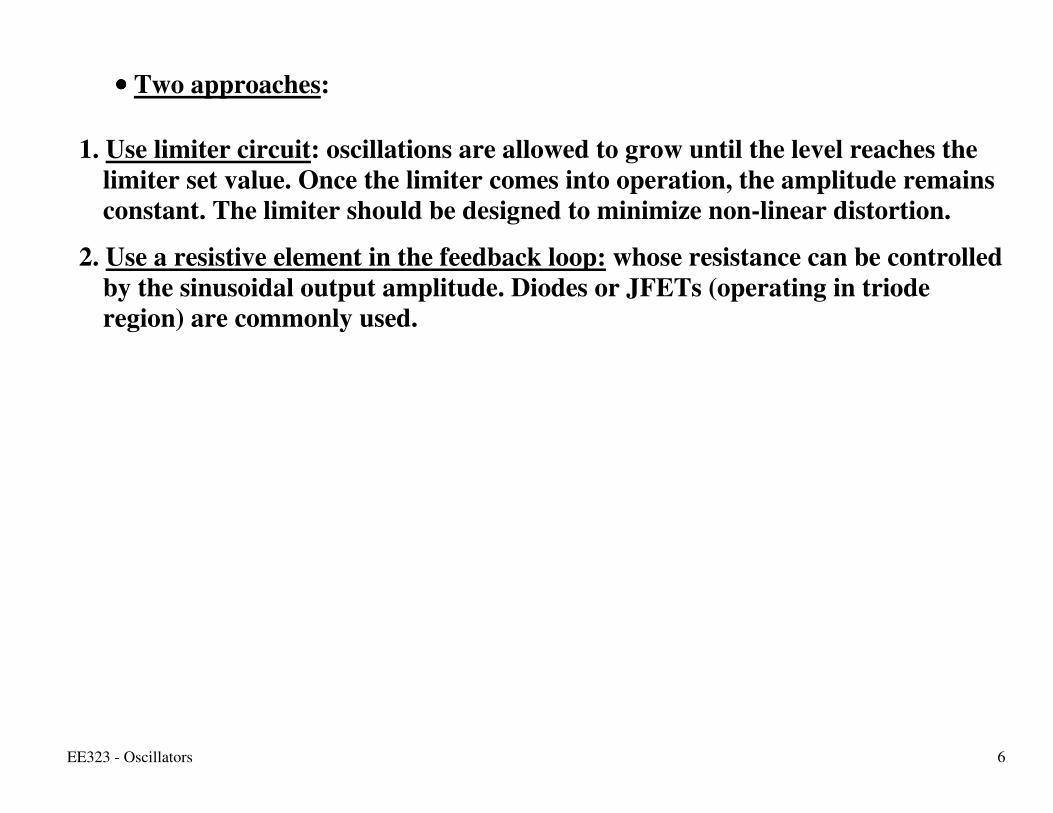
1. Use limiter circuit: oscillations are allowed to grow until the level reaches the limiter set value. Once the limiter comes into operation, the amplitude remains constant. The limiter should be designed to minimize non-linear distortion.
2. Use a resistive element in the feedback loop: whose resistance can be controlled by the sinusoidal output amplitude. Diodes or JFETs (operating in triode region) are commonly used.

EE323 - Oscillators 7
A popular limiter circuit:

EE323 - Oscillators 8
II. OP-AMP- RC OSCILLATORS:
1. WIEN-BRIDGE OSCILLATOR
•••• Loop gain:
SP
P
1
2ZZ
Z]RR1[)s(L
++++••••++++====
A(s) ββββ(s)

EE323 - Oscillators 9
)RC�
1RC�(j3
RR1
)�j(L 1
2
−−−−++++
++++====
•••• The loop gain will be a real number (i.e., the phase will be zero when imaginary part = 0) at one frequency:
RC1
�
RC�
1RC�
0
00
====
====
•••• To sustain oscillation at this frequency, the magnitude of the loop gain should be unity by setting
2
RR
1
2 ====
•••• To ensure oscillation start, choose R2/R1 slightly greater than 2.
•••• The amplitude of the oscillation can be controlled using a non-linear limiter.
EE323 - Oscillators 10
EE323 - Oscillators 11
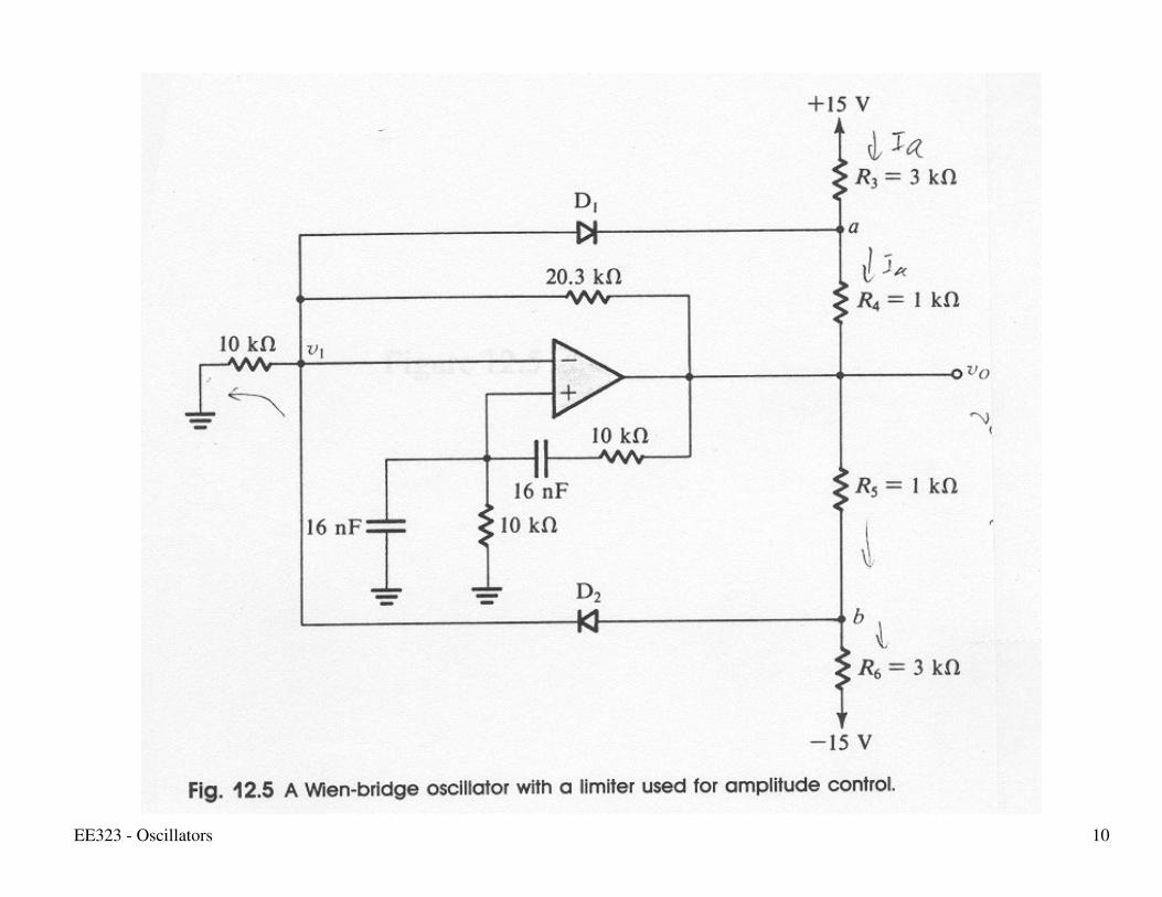
2. PHASE SHIFT OSCILLATOR
•••• Consists of a negative gain amplifier (-K) with a three-section (3rd order) RC ladder network in the feedback.
•••• The circuit will oscillate at the frequency when the phase shift of the RC network is 180O. •••• Only at this frequency the phase shift around the loop be 0O (360O). •••• Three RC sections are required to produce a 180O phase shift at a finite frequency.

EE323 - Oscillators 12
•••• The value of K is chosen to be slightly higher than the inverse of the magnitude of the RC network transfer function at the frequency of oscillation.

EE323 - Oscillators 13
3. ACTIVE FILTER TUNED OSCILLATOR
EE323 - Oscillators 14
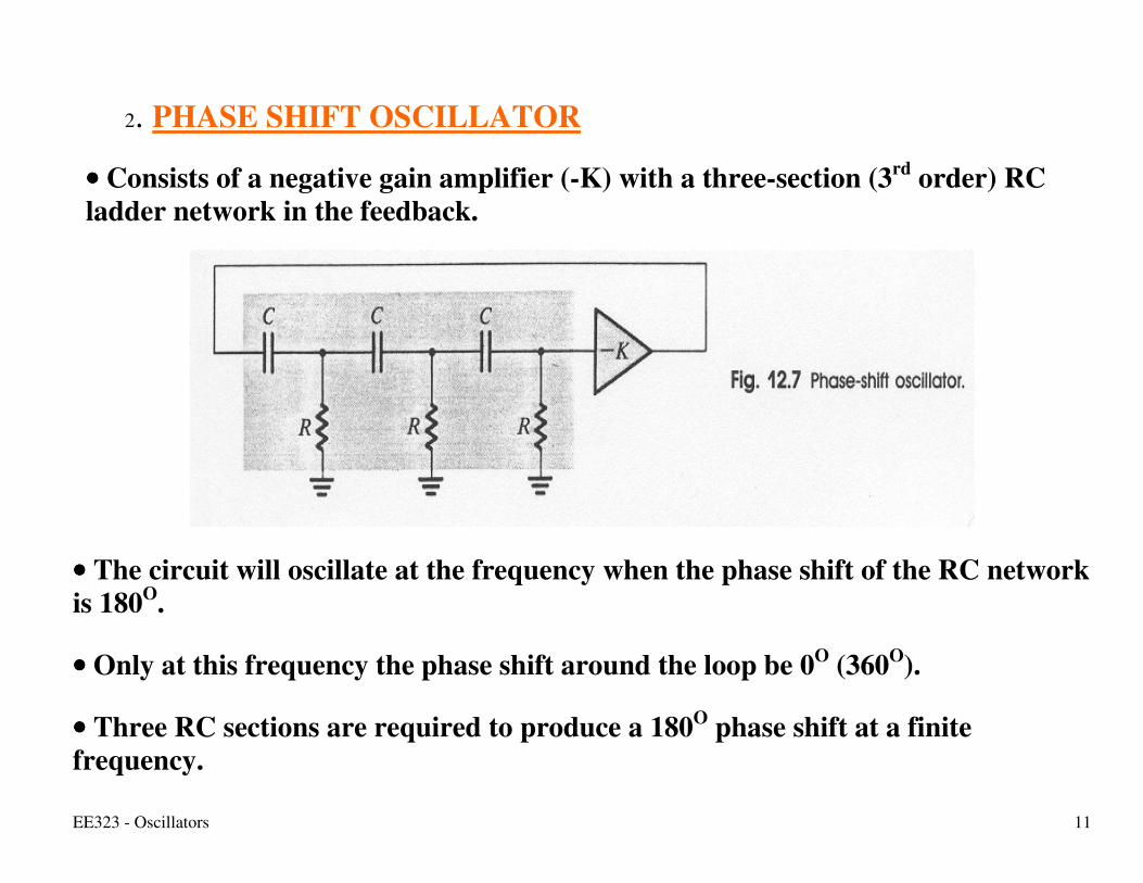
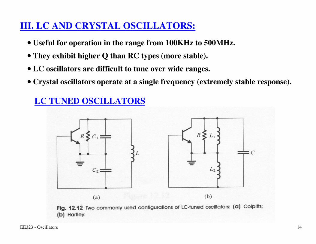
III. LC AND CRYSTAL OSCILLATORS:
•••• Useful for operation in the range from 100KHz to 500MHz. •••• They exhibit higher Q than RC types (more stable). •••• LC oscillators are difficult to tune over wide ranges. •••• Crystal oscillators operate at a single frequency (extremely stable response).
LC TUNED OSCILLATORS

EE323 - Oscillators 15
•••• Frequency of oscillation is determined by the resonant frequency of the parallel tuned circuit (i.e., tank circuit).
For Colpitts oscillator: )CC
CC(L
1�
21
210
++++
====
For Hartley oscillator: )LL(C1
�21
0 ++++====
EE323 - Oscillators 16
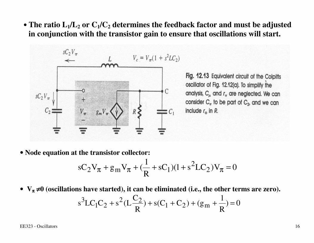
• The ratio L1/L2 or C1/C2 determines the feedback factor and must be adjusted in conjunction with the transistor gain to ensure that oscillations will start.
• Node equation at the transistor collector:
0V)LCs1)(sCR1
(VgVsC 22
1m2 =++++ πππ
• Vππππ ≠≠≠≠0 (oscillations have started), it can be eliminated (i.e., the other terms are zero).
0)R1
g()CC(s)R
CL(sCLCs m21
2221
3 =+++++

EE323 - Oscillators 17
0]CLC�)CC(�[j)RLC�
R1g( 21
321
22
m ====−−−−++++++++−−−−++++
•••• For oscillations to start, both real and imaginary parts must be 0. •••• Setting the imaginary part to zero:
)
CC
CC(L
1�
21
20
1
++++
====
which is the resonant frequency of the tank circuit.
• Setting the real part to zero: RgCC
m1
2 ====
•••• To sustain oscillation, the magnitude of the gain from the base to collector (gmR) must be equal to the inverse of the voltage ratio provided by the capacitive divider.
2
1
ce
beCC
vv ====

EE323 - Oscillators 18
• To start oscillation, the loop gain must be greater than unity:
1
2m C
CRg >>>>
•••• As oscillation grows in amplitude, the transistors non-linear characteristics reduce the loop gain to unity, thus sustaining oscillations.

EE323 - Oscillators 19
•••• LC tuned oscillators utilize the non-linear ic-vbe characteristics of the BJT (or id versus vgs for FET) for amplitude control.
•••• As the oscillations grow, the effective gain of the transistor is reduced below its small signal value.
•••• The LC tuned oscillators are known as self-limiting oscillators.
•••• Reliance on the non-linear characteristics of the BJT (or the FET) implies that the collector (drain) current waveform will be nonlinearity distorted.
•••• Nevertheless, sinusoidal of high purity because of the filtering action of the LC tuned circuit.

EE323 - Oscillators 20
CRYSTAL OSCILLATORS •••• Electro-mechanical resonance •••• Very stable (with time and temperature) •••• Very high selectivity (having very high Q factor).

EE323 - Oscillators 21
•••• Large inductance L (as high as hundreds of Henrys), •••• A very small series capacitance Cs (as small as 0.0005pF), •••• A parallel capacitance Cp (a few picoFarad), represents the electrostatic
capacitance between the two parallel plates of the crystal (Cp>>Cs), •••• A small series resistance r, •••• A high Q factor (ωωωω0L/r): as high as few hundred thousand. Neglect the resistance r (high Q) and express the crystal impedance as:
sp sC/1sL
1sC
1)s(Z
++++++++
====
or
)CC(L
CCs
LC1s
psp
sp2
s
2
sC1)s(Z
++++++++
++++====

EE323 - Oscillators 22
Two resonant frequencies (series and parallel):
ps
psp
ss
CCCC
L
1�and
LC1
�
++++
========
•••• ωωωωp>ωωωωs and Cp>>Cs, the two resonant frequencies are very close. •••• Cs dominates (much smaller than the other capacitances):
ss
0 LC1 ω==ω
•••• For s=jωωωω
)
��
��(
C�1j)�j(Z
2p
2
2s
2
p −−−−
−−−−−−−−====

EE323 - Oscillators 23
•••• Crystal reactance is inductive over a narrow frequency band between ωωωωp and ωωωωs.
•••• Use the crystal to replace the inductor in a Colpitts oscillator.
•••• Circuit will oscillate at the resonant frequency of the crystal inductance L with
the series equivalent of Cs and )CC
CCC(
21
21p ++++
++++ .

EE323 - Oscillators 24
IV. MULTIVIBRATORS:
1. Bistable Multivibrator: •••• Two stable states. •••• Circuit has 2 stable states: positive saturation and negative saturation. •••• Circuit can remain in either stable state indefinitely. •••• Moves to the other stable state only when triggered. •••• Obtained by connecting an amplifier in a positive feedback loop having loop gain
greater than unity.

EE323 - Oscillators 25
Triggering the bistable circuit:
Trigger signal

EE323 - Oscillators 26
•••• vI initiates or triggers regeneration (can be removed with no effect on the regeneration process). •••• vI can simply be a pulse (i.e., trigger signal). The circuit is known as the Schmitt trigger.
A simple change in the input converts the circuit into a non-inverting bistable circuit.

EE323 - Oscillators 27
The output levels of the bistable circuit adjusted by cascading the op-amp with a limiter circuit.

EE323 - Oscillators 28
2. Astable Multivibrator:
•••• No stable state (astable). •••• A square waveform can be generated by making a bistable multivibrator switch
state periodically. •••• Connecting a bistable mutivibrator with an RC circuit in the feedback loop.

EE323 - Oscillators 29

EE323 - Oscillators 30
RC�wheree)L�L(Lv �
t
====−−−−−−−−====−−−−
−−−−++++++++−−−−
Charging: v-=ββββL+ at t=T1 ���� )�1LL�1
ln(�T1 −−−−
−−−−==== ++++
−−−−
Similarly for the discharge cycle, )�1LL�1
ln(�T2 −−−−
−−−−==== −−−−
++++
If L+=L- and T=T1+T2 then
�1�1ln�2T
−−−−++++====
•••• Adjusting C and/or R varies frequency. •••• Waveform across C can be made almost triangular by using a small value for the
parameter ββββ.

EE323 - Oscillators 31
Generation of triangle waveforms:
•••• The exponential waveform generated in the astable circuit can be changed to triangular by replacing the low pass RC circuit with an integrator.
•••• The integrator causes linear charging and discharging of the capacitor. •••• The integrator is inverting, it is necessary to use the non-inverting bistable
circuit.

EE323 - Oscillators 32
−−−−
−−−−
++++
++++
−−−−−−−−====
−−−−====−−−−
−−−−========−−−−
LVVCRT
CRL
TVV
LVVCRT
CRL
TVV
TLTH2
1
TLTH
TLTH1
1
TLTH
IF L+=L- then symmetrical waveforms are obtained

EE323 - Oscillators 33
3. Monostable Multivibrator:
• Need a pulse of known height and width generated in response to a trigger signal. •••• The width of the pulse is predictable, its trailing edge used for timing purposes. •••• Generated by a monostable multivibrator. •••• Has one stable state which can remain indefinitely. •••• Has a quasi-stable state (remains for a predetermined interval equal to the
desired width of the output pulse). •••• Once the interval expires, returns to the stable state and remains there awaiting
another triggering signal. •••• The circuit is commonly called a one shot. •••• Is an augmented form of the astable circuit.

EE323 - Oscillators 34
31RC
t
1DB e)VL(L)t(v−−−−
−−−−−−−− −−−−−−−−====

EE323 - Oscillators 35
Substitute vB(T)=ββββL-,
)
LL�LV
ln(RCT
e)VL(LL�
1D31
RCT
1D 31
−−−−−−−−
−−−−
−−−−
−−−−−−−−−−−−
−−−−−−−−
====
−−−−−−−−====
For VD1 << |L-|, )�1
1ln(RCT 31 −−−−≈≈≈≈
Note: should not be re-triggered again until C1 has been recharged to VD1 (recovery period).

EE323 - Oscillators 36
INTEGRATED CIRCUIT TIMERS
•••• To implement monostable and astable multivibrators having precise characteristics.
•••• Most popular is the 555 timer.
EE323 - Oscillators 37
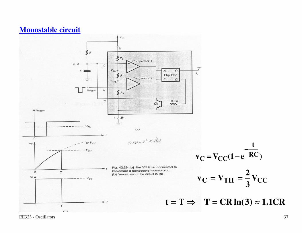
Monostable circuit
)e1(Vv RCt
CCC−−−−
−−−−====
CCTHC V32Vv ========
CR1.1)3ln(CRTTt ≈≈≈≈====����====

EE323 - Oscillators 38
Astable circuit:

EE323 - Oscillators 39
Rise in vC :
Fall in vC :
Total period :
)RR(C69.0)2ln()RR(CT
V31VTtV
32Vv
e)VV(Vv
BABAH
CCTLHCCTHC
)RR(Ct
TLCCCCC BA
++++≈≈≈≈++++====
====����============
−−−−−−−−==== ++++−−−−
BBL
CCTHLCCTLC
CRt
THC
CR69.0)2ln(CRT
V32VTtV
31Vv
eVv B
≈≈≈≈====
====����============
====−−−−
)R2R(C69.0TTT BALH ++++====++++====