chapter 14 nonsinusoidal oscillators. objectives describe and analyze: operation of the 555 ic...
TRANSCRIPT
CHAPTER 14
Nonsinusoidal
Oscillators
Objectives
Describe and Analyze:• Operation of the 555 IC• Inverter oscillators• Schmitt oscillators• Wave-shaping• Sawtooth oscillators• Troubleshooting
Introduction
• There are other ways to make an oscillator besides phase-shifters and resonators.
• The term astable covers a group of oscillator circuits, many based on hysteresis in one form or another. It also covers chips designed for the purpose, such as the 555.
• The old term “multivibrator” is also used to name these circuits. It goes back to vacuum tube days when they actually used electromechanical vibrators in circuits.
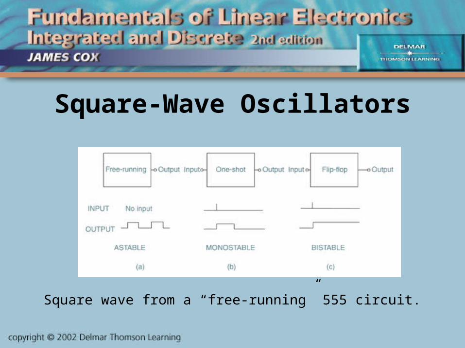
Square-Wave Oscillators
Square wave from a “free-running” 555 circuit.

The “Internals” of a 555
Frequency set by RA, RB, and C.
Functions of the 555• The 555 is still popular after all these years because
it is easy to use. It performs two functions:– Square-wave oscillator (astable)– One-shot (monostable)
• Strictly speaking, a square-wave has a 50% duty cycle. But unless the duty cycle is low, astables are called square-wave oscillators even if it’s not 50%.
• A one-shot produces a fixed-width output pulse every time it is “triggered” by a rising or falling edge at its input.
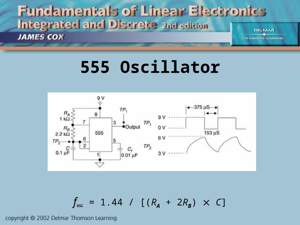
555 Oscillator
fOSC = 1.44 / [(RA + 2RB) C]
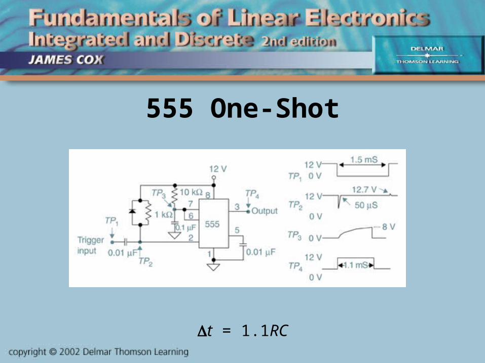
555 One-Shot
t = 1.1RC
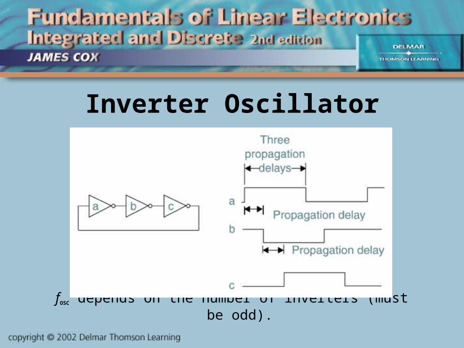
Inverter Oscillator
fOSC depends on the number of inverters (must be odd).
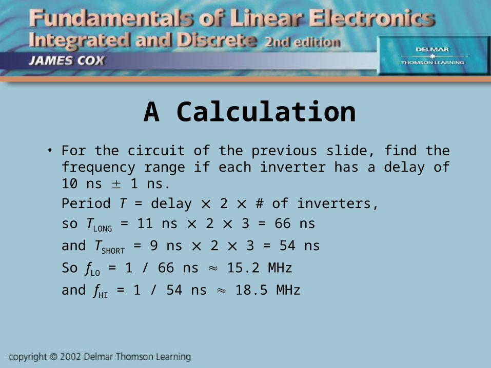
A Calculation• For the circuit of the previous slide, find the frequency
range if each inverter has a delay of 10 ns 1 ns.
Period T = delay 2 # of inverters,
so TLONG = 11 ns 2 3 = 66 ns
and TSHORT = 9 ns 2 3 = 54 ns
So fLO = 1 / 66 ns 15.2 MHz
and fHI = 1 / 54 ns 18.5 MHz
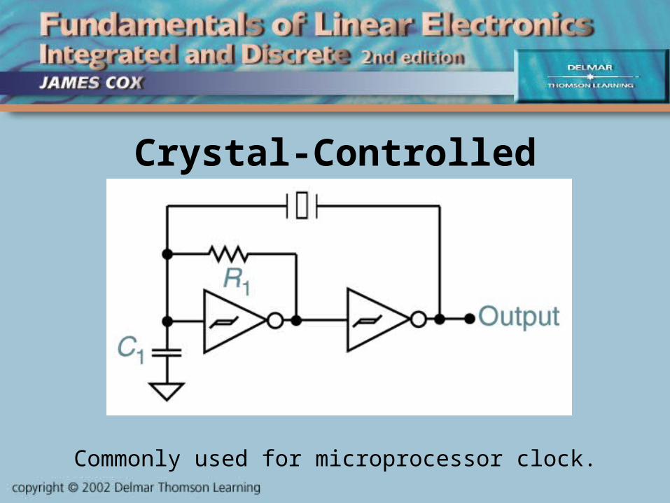
Crystal-Controlled
<insert figure 14-15 here>
Commonly used for microprocessor clock.
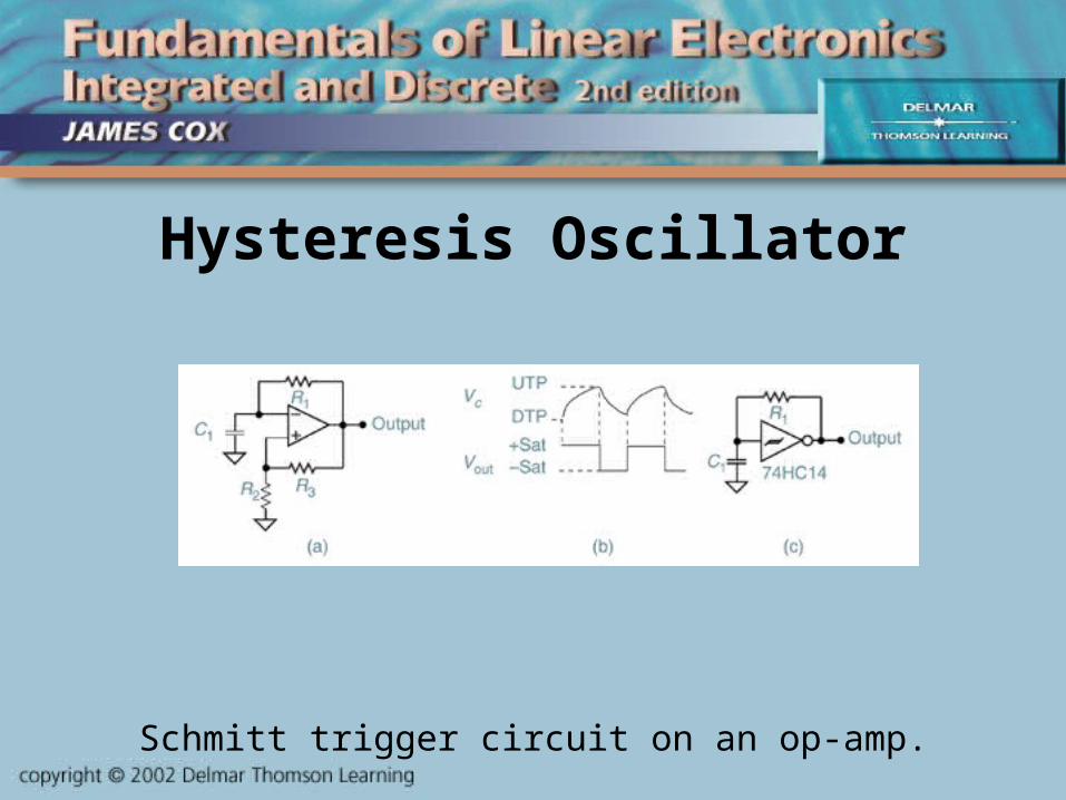
Hysteresis Oscillator
Schmitt trigger circuit on an op-amp.
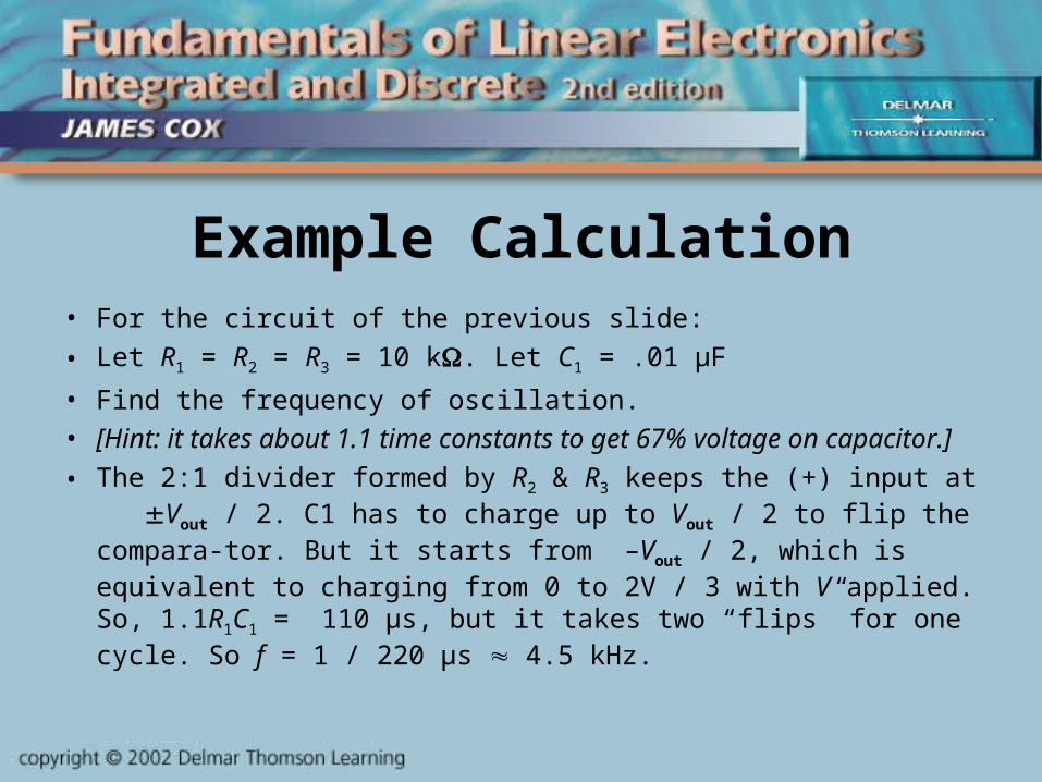
Example Calculation• For the circuit of the previous slide:
• Let R1 = R2 = R3 = 10 k. Let C1 = .01 μF
• Find the frequency of oscillation. • [Hint: it takes about 1.1 time constants to get 67% voltage on
capacitor.]
• The 2:1 divider formed by R2 & R3 keeps the (+) input at Vout / 2. C1 has to charge up to Vout / 2 to flip the compara-tor. But it starts from –Vout / 2, which is equivalent to charging from 0 to 2V / 3 with V applied. So, 1.1R1C1 = 110 μs, but it takes two “flips” for one cycle. So f = 1 / 220 μs 4.5 kHz.

Square to Triangle
Integrating a square wave makes a triangle wave.
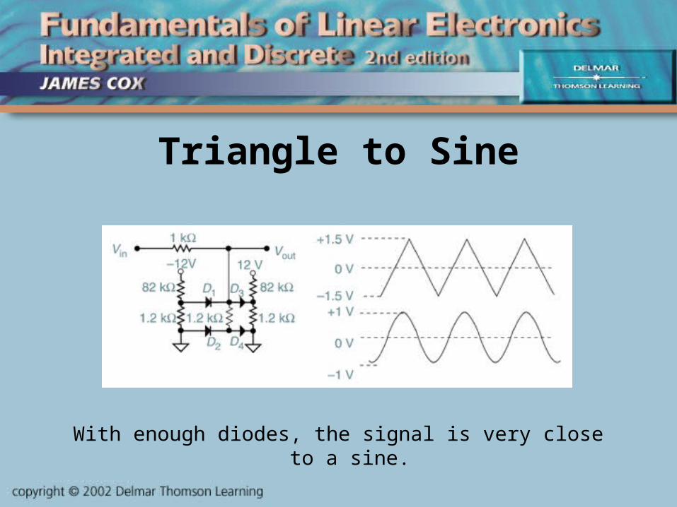
Triangle to Sine
With enough diodes, the signal is very close to a sine.
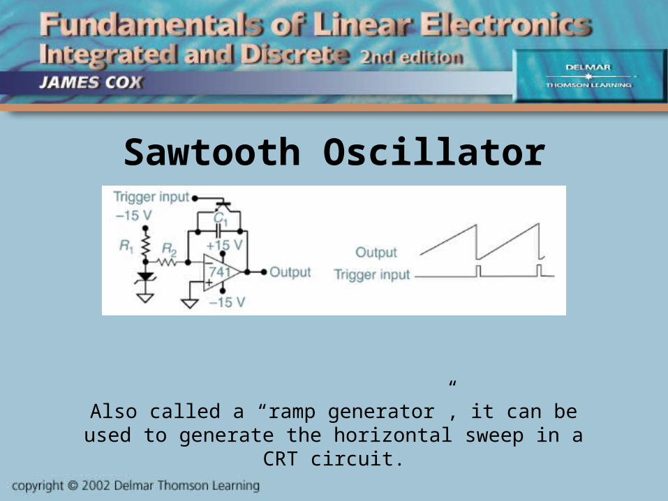
Sawtooth Oscillator
Also called a “ramp generator”, it can be used to generate the horizontal sweep in a CRT circuit.
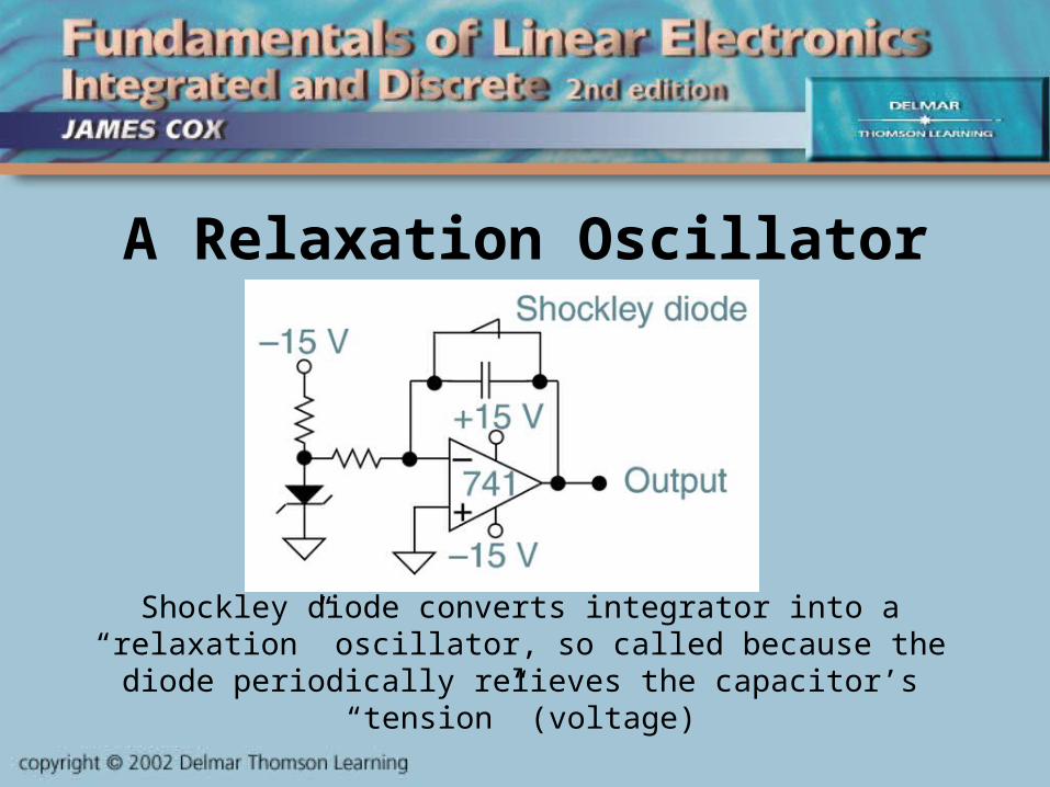
A Relaxation Oscillator
Shockley diode converts integrator into a “relaxation” oscillator, so called because the diode periodically
relieves the capacitor’s “tension” (voltage)

Sample Calculation
• For the circuit of the previous slide, let the input resistor Ri = 100 k, the feedback capacitor C = 0.1 F, and let Vin = –1 Volt. Calculate the frequency if the Shockley diode “fires” at 10 Volts.
• Iin = 1V / 100 k = 10 A, and charging a capacitor with a constant current means the voltage ramps up linearly at a rate of V / t = I / C. So t = (C / I) V.
• The period T = (0.1 F / 10 A) 10 Volts = 0.1 sec.• So f = 1 / T = 10 Hertz.
Troubleshooting• As always, check all DC voltages.• Typically, these oscillators either work or they do
not; they do not tend to drift.• Frequencies are not precise (except for crystal
stabilized) so oscilloscope measurements are OK.• Though not often used, if an aluminum electrolytic is
the timing capacitor, it is a suspect.• If a potentiometer is used to adjust an RC time
constant, check if it has been “tweaked”.• Look for physical damage to components.