os and libraries document collection - xilinx - all … and libraries document collection table 1:...
TRANSCRIPT
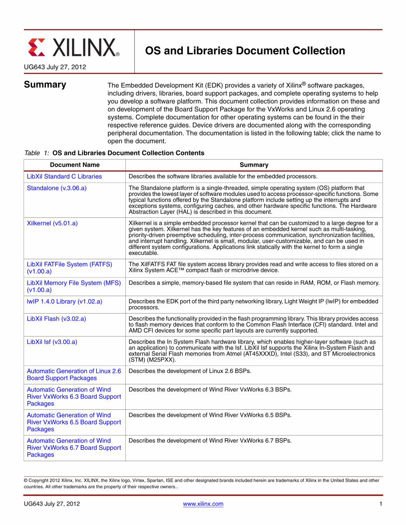
Summary The Embedded Development Kit (EDK) provides a variety of Xilinx® software packages, including drivers, libraries, board support packages, and complete operating systems to help you develop a software platform. This document collection provides information on these and on development of the Board Support Package for the VxWorks and Linux 2.6 operating systems. Complete documentation for other operating systems can be found in the their respective reference guides. Device drivers are documented along with the corresponding peripheral documentation. The documentation is listed in the following table; click the name to open the document.
UG643 July 27, 2012
OS and Libraries Document Collection
Table 1: OS and Libraries Document Collection Contents
Document Name Summary
LibXil Standard C Libraries Describes the software libraries available for the embedded processors.
Standalone (v.3.06.a) The Standalone platform is a single-threaded, simple operating system (OS) platform that provides the lowest layer of software modules used to access processor-specific functions. Some typical functions offered by the Standalone platform include setting up the interrupts and exceptions systems, configuring caches, and other hardware specific functions. The Hardware Abstraction Layer (HAL) is described in this document.
Xilkernel (v5.01.a) Xilkernel is a simple embedded processor kernel that can be customized to a large degree for a given system. Xilkernel has the key features of an embedded kernel such as multi-tasking, priority-driven preemptive scheduling, inter-process communication, synchronization facilities, and interrupt handling. Xilkernel is small, modular, user-customizable, and can be used in different system configurations. Applications link statically with the kernel to form a single executable.
LibXil FATFile System (FATFS) (v1.00.a)
The XilFATFS FAT file system access library provides read and write access to files stored on a Xilinx System ACE™ compact flash or microdrive device.
LibXil Memory File System (MFS) (v1.00.a)
Describes a simple, memory-based file system that can reside in RAM, ROM, or Flash memory.
lwIP 1.4.0 Library (v1.02.a) Describes the EDK port of the third party networking library, Light Weight IP (lwIP) for embedded processors.
LibXil Flash (v3.02.a) Describes the functionality provided in the flash programming library. This library provides access to flash memory devices that conform to the Common Flash Interface (CFI) standard. Intel and AMD CFI devices for some specific part layouts are currently supported.
LibXil Isf (v3.00.a) Describes the In System Flash hardware library, which enables higher-layer software (such as an application) to communicate with the Isf. LibXil Isf supports the Xilinx In-System Flash and external Serial Flash memories from Atmel (AT45XXXD), Intel (S33), and ST Microelectronics (STM) (M25PXX).
Automatic Generation of Linux 2.6 Board Support Packages
Describes the development of Linux 2.6 BSPs.
Automatic Generation of Wind River VxWorks 6.3 Board Support Packages
Describes the development of Wind River VxWorks 6.3 BSPs.
Automatic Generation of Wind River VxWorks 6.5 Board Support Packages
Describes the development of Wind River VxWorks 6.5 BSPs.
Automatic Generation of Wind River VxWorks 6.7 Board Support Packages
Describes the development of Wind River VxWorks 6.7 BSPs.
UG643 July 27, 2012 www.xilinx.com 1
© Copyright 2012 Xilinx, Inc. XILINX, the Xilinx logo, Virtex, Spartan, ISE and other designated brands included herein are trademarks of Xilinx in the United States and other countries. All other trademarks are the property of their respective owners..
About the Libraries
About the Libraries
The Standard C support library consists of the newlib, libc, which contains the standard C functions such as stdio, stdlib, and string routines. The math library is an enhancement over the newlib math library, libm, and provides the standard math routines.
The LibXil libraries consist of the following:
• LibXil Driver (Xilinx device drivers)
• LibXil MFS (Xilinx memory file system)
• LibXil Flash (a parallel flash programming library)
• LibXil Isf (a serial flash programming library)
There are two operating system options provided in the Xilinx software package: the Standalone Platform and Xilkernel.
The Hardware Abstraction Layer (HAL) provides common functions related to register IO, exception, and cache. These common functions are uniform across MicroBlaze™, PowerPC® 405, and PowerPC 440 processors. The Standalone platform document provides some processor specific functions and macros for accessing the processor-specific features.
Most routines in the library are written in C and can be ported to any platform. The Library Generator (Libgen) configures the libraries for an embedded processor, using the attributes defined in the Microprocessor Software Specification (MSS) file.
User applications must include appropriate headers and link with required libraries for proper compilation and inclusion of required functionality. These libraries and their corresponding include files are created in the processor \lib and \include directories, under the current project, respectively. The -I and -L options of the compiler being used should be leveraged to add these directories to the search paths. Libgen tailors the compilation of each software component. Refer to the “Libgen” and “Microprocessor Software Specification” chapters in the Embedded Systems Tools Reference Manual (UG111) for more information. See “Additional Resources,” page 3 for a link to the document.
UG643 July 27, 2012 www.xilinx.com 2

Library Organization
Library Organization
The organization of the libraries is illustrated in the figure below. As shown, your application can interface with the components in a variety of ways. The libraries are independent of each other, with the exception of some interactions. For example, Xilkernel uses the Standalone platform internally. The LibXil Drivers and the Standalone form the lowermost hardware abstraction layer. The library and OS components rely on standard C library components. The math library, libm.a is also available for linking with the user applications.
Note: “LibXil Drivers” are the device drivers included in the software platform to provide an interface to the peripherals in the system. These drivers are provided along with EDK and are configured by Libgen. This document collection contains a section that briefly discusses the concept of device drivers and the way they integrate with the board support package in EDK.
Taking into account some restrictions and implications, which are described in the reference guides for each component, you can mix and match the component libraries.
X-Ref Target - Figure 2
Additional Resources
Xilinx Resources • Xilinx Design Tools: Installation and Licensing Guide (UG798):
http://www.xilinx.com/support/documentation/sw_manuals/xilinx14_2/iil.pdf
• Xilinx Design Tools: Release Notes Guide (UG631): http://www.xilinx.com/support/documentation/sw_manuals/xilinx14_2/irn.pdf
• Xilinx® Documentation: http://www.xilinx.com/support/documentation.htm
• Xilinx Glossary: http://www.xilinx.com/support/documentation/sw_manuals/glossary
• Xilinx Support: http://www.xilinx.com/support.htm
Figure 1: Library Organization
stdio
stdlib
string
Other
X10968_102908
User Application
Xilkernel
XilFlash
C, Math and GCC Libraries
XilMFS
Standalone
XillSF
Xilinx Drivers
UG643 July 27, 2012 www.xilinx.com 3

Revision History
EDK Documentation
The following documents are available online at: http://www.xilinx.com/ise/embedded/edk_docs.htm.
Individual documents are linked below.
• EDK Concepts, Tools, and Techniques (UG683):http://www.xilinx.com/support/documentation/sw_manuals/xilinx14_2/edk_ctt.pdf
• Embedded System Tools Reference Manual (UG111): http://www.xilinx.com/support/documentation/sw_manuals/xilinx14_2/est_rm.pdf
• Platform Specification Format Reference Manual (UG642): http://www.xilinx.com/support/documentation/sw_manuals/xilinx14_2/psf_rm.pdf
• EDK Profiling Guide (UG448): http://www.xilinx.com/support/documentation/sw_manuals/xilinx14_2/edk_prof.pdf
• PowerPC 405 Processor Block Reference Guide (UG018): http://www.xilinx.com/support/documentation/user_guides/ug018.pdf
• PowerPC 405 Processor Reference Guide (UG011): http://www.xilinx.com/support/documentation/user_guides/ug011.pdf
• PowerPC 440 Embedded Processor Block in Virtex®-5 FPGAs (UG200): http://www.xilinx.com/support/documentation/user_guides/ug200.pdf
• MicroBlaze Processor User Guide (UG081): http://www.xilinx.com/support/documentation/sw_manuals/xilinx14_2/mb_ref_guide.pdf
• SDK Help: http://www.xilinx.com/support/documentation/sw_manuals/xilinx14_2/SDK_Doc/index.html
• XPS Help: http://www.xilinx.com/support/documentation/sw_manuals/xilinx14_2/platform_studio/platform_studio_start.htm
Revision History
The following table lists the revision history of the OS and Libraries Document Collection
Date Version Revision
07/06/2011 13.2 • Added EDK Resources section.• New XilIsf version (v2.03.a) that lists explicit device numbers.• XilFlash (v3.00.a) Added two parameters (ENABLE_INTEL and
ENABLE_AMD) to the Libgen customization.
01/18/2012 13.4 • New Standalone version (v3.03.a).• New lwIP version (1.4.0 v1.01.a)• Updated Additional Resource links.
04/24/2012 14.1 • New Standalone version (v3.05.a).• New version of LibXil Flash (v3.01.a)
07/25/2012 14.2 • New version of LibXil Flash (v3.02.a)• New version of LibXil ISF (v3.00.a)• New version of lwIP (1.4.0 v1.02.a)• New version of Standalone (v3.06.a)
07/27/2012 14.2 • Updated links to additional resource documents on page 4.
UG643 July 27, 2012 www.xilinx.com 4

Overview The Xilinx® Embedded Development Kit (EDK) libraries and device drivers provide standard C library functions, as well as functions to access peripherals. The EDK libraries are automatically configured by Libgen for every project based on the Microprocessor Software Specification (MSS) file. These libraries and include files are saved in the current project lib and include directories, respectively. The -I and -L options of mb-gcc are used to add these directories to its library search paths.
Additional Resources
• MicroBlaze Processor Reference Guide (UG081)http://www.xilinx.com/ise/embedded/mb_ref_guide.pdf
• Embedded System Tools Reference Manual (UG111): http://www.xilinx.com/support/documentation/sw_manuals/xilinx14_2/est_rm.pdf
Standard C Library (libc.a)
The standard C library, libc.a, contains the standard C functions compiled for the MicroBlaze™ processor or the PowerPC® processor. You can find the header files corresponding to these C standard functions in <XILINX_EDK>/gnu/<processor>/<platform>/<processor-lib>/include, where:
• <XILINX_EDK> is the <Installation directory>
• <processor> is powerpc-eabi or microblaze
• <platform> is sol, nt, or lin
• <processor-lib> is powerpc-eabi or microblaze-xilinx-elf
The lib.c directories and functions are:
Programs accessing standard C library functions must be compiled as follows:
For MicroBlaze processors:
mb-gcc <C files>
For PowerPC processors:
powerpc-eabi-gcc <C files>
The libc library is included automatically.
For programs that access libm math functions, specify the lm option.
UG645 July 6, 2011
LibXil Standard C Libraries
_ansi.h fastmath.h machine/ reent.h stdlib.h utime.h
_syslist.h fcntl.h malloc.h regdef.h string.h utmp.h
ar.h float.h math.h setjmp.h sys/
assert.h grp.h paths.h signal.h termios.h
ctype.h ieeefp.h process.h stdarg.h time.h
dirent.h limits.h pthread.h stddef.h unctrl.h
errno.h locale.h pwd.h stdio.h unistd.h
UG645 July 6, 2011 www.xilinx.com 1
© 2011 Xilinx, Inc. XILINX, the Xilinx logo, Virtex, Spartan, ISE, and other designated brands included herein are trademarks of Xilinx in the United States and other countries. All other trademarks are the property of their respective owners.

Xilinx C Library (libxil.a)
Refer to the “MicroBlaze Application Binary Interface (ABI)” section in the MicroBlaze Processor Reference Guide (UG081) for information on the C Runtime Library. “Additional Resources,” page 1 contains a link to the document.
Xilinx C Library (libxil.a)
The Xilinx C library, libxil.a, contains the following object files for the MicroBlaze processor embedded processor:
_exception_handler.o_interrupt_handler.o_program_clean.o_program_init.o
Default exception and interrupt handlers are provided. The libxil.a library is included automatically.
Programs accessing Xilinx C library functions must be compiled as follows:
mb-gcc <C files>
Input/Output Functions
The EDK libraries contains standard C functions for I/O, such as printf and scanf. These functions are large and might not be suitable for embedded processors.
The prototypes for these functions are in stdio.h.
Note: The C standard I/O routines such as printf, scanf, vfprintf are, by default, line buffered. To change the buffering scheme to no buffering, you must call setvbuf appropriately. For example:
setvbuf (stdout, NULL, _IONBF, 0);
These Input/Output routines require that a newline is terminated with both a CR and LF. Ensure that your terminal CR/LF behavior corresponds to this requirement.
Refer to the “Microprocessor Software Specification (MSS)” chapter in the Embedded System Tools Reference Manual (UG111) for information on setting the standard input and standard output devices for a system. “Additional Resources,” page 1 contains a link to the document.
In addition to the standard C functions, the EDK processors (MicroBlaze processor and PowerPC 405 processor) library provides the following smaller I/O functions:
void print (char *)
This function prints a string to the peripheral designated as standard output in the Microprocessor Software Specification (MSS) file. This function outputs the passed string as is and there is no interpretation of the string passed. For example, a “\n” passed is interpreted as a new line character and not as a carriage return and a new line as is the case with ANSI C printf function.
void putnum (int)
This function converts an integer to a hexadecimal string and prints it to the peripheral designated as standard output in the MSS file.
void xil_printf (const *char ctrl1,...)
xil_printf is a light-weight implementation of printf. It is much smaller in size (only 1 kB). It does not have support for floating point numbers. xil_printf also does not support printing of long (such as 64-bit) numbers.
Note: About Format String Support:
UG645 July 6, 2011 www.xilinx.com 2
Input/Output Functions
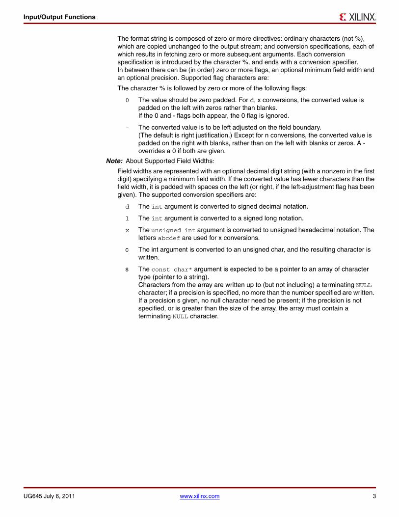
The format string is composed of zero or more directives: ordinary characters (not %), which are copied unchanged to the output stream; and conversion specifications, each of which results in fetching zero or more subsequent arguments. Each conversion specification is introduced by the character %, and ends with a conversion specifier. In between there can be (in order) zero or more flags, an optional minimum field width and an optional precision. Supported flag characters are:
The character % is followed by zero or more of the following flags:
0 The value should be zero padded. For d, x conversions, the converted value is padded on the left with zeros rather than blanks. If the 0 and - flags both appear, the 0 flag is ignored.
- The converted value is to be left adjusted on the field boundary. (The default is right justification.) Except for n conversions, the converted value is padded on the right with blanks, rather than on the left with blanks or zeros. A - overrides a 0 if both are given.
Note: About Supported Field Widths:
Field widths are represented with an optional decimal digit string (with a nonzero in the first digit) specifying a minimum field width. If the converted value has fewer characters than the field width, it is padded with spaces on the left (or right, if the left-adjustment flag has been given). The supported conversion specifiers are:
d The int argument is converted to signed decimal notation.
l The int argument is converted to a signed long notation.
x The unsigned int argument is converted to unsigned hexadecimal notation. The letters abcdef are used for x conversions.
c The int argument is converted to an unsigned char, and the resulting character is written.
s The const char* argument is expected to be a pointer to an array of character type (pointer to a string). Characters from the array are written up to (but not including) a terminating NULL character; if a precision is specified, no more than the number specified are written. If a precision s given, no null character need be present; if the precision is not specified, or is greater than the size of the array, the array must contain a terminating NULL character.
UG645 July 6, 2011 www.xilinx.com 3

Memory Management Functions
Memory Management Functions
The MicroBlaze processor and PowerPC processor C libraries support the standard memory management functions such as malloc( ), calloc( ), and free( ). Dynamic memory allocation provides memory from the program heap. The heap pointer starts at low memory and grows toward high memory. The size of the heap cannot be increased at runtime. Therefore an appropriate value must be provided for the heap size at compile time. The malloc( ) function requires the heap to be at least 128 bytes in size to be able to allocate memory dynamically (even if the dynamic requirement is less than 128 bytes). The return value of malloc must always be checked to ensure that it could actually allocate the memory requested.
Arithmetic Operations
Software implementations of integer and floating point arithmetic is available as library routines in libgcc.a for both processors. The compiler for both the processors inserts calls to these routines in the code produced, in case the hardware does not support the arithmetic primitive with an instruction.
MicroBlaze Processor
Integer Arithmetic
By default, integer multiplication is done in software using the library function __mulsi3. Integer multiplication is done in hardware if the mb-gcc option, -mno-xl-soft-mul, is specified.
Integer divide and mod operations are done in software using the library functions __divsi3 and __modsi3. The MicroBlaze processor can also be customized to use a hard divider, in which case the div instruction is used in place of the __divsi3 library routine.
Double precision multiplication, division and mod functions are carried out by the library functions __muldi3, __divdi3, and __moddi3, respectively.
The unsigned version of these operations correspond to the signed versions described above, but are prefixed with an __u instead of __.
Floating Point Arithmetic
All floating point addition, subtraction, multiplication, division, and conversions are implemented using software functions in the C library.
PowerPC Processor
Integer Arithmetic
Integer addition and subtraction operations are provided in hardware; no specific software library is available for the PowerPC processor.
Floating Point Arithmetic
The PowerPC processor supports all floating point arithmetic implemented in the standard C library.
Thread Safety The standard C library provided with EDK is not built for a multi-threaded environment. STDIO functions like printf(), scanf() and memory management functions like malloc() and free() are common examples of functions that are not thread-safe. When using the C library in a multi-threaded environment, proper mutual exclusion techniques must be used to protect thread unsafe functions.
UG645 July 6, 2011 www.xilinx.com 4

Summary Standalone is the lowest layer of software modules used to access processor specific functions. Standalone is used when an application accesses board/processor features directly and is below the operating system layer.
This document contains the following sections:
• MicroBlaze Processor API
• PowerPC 405 Processor API
• PowerPC 440 Processor API
• Cortex A9 Processor API
• Xilinx Hardware Abstraction Layer
• Program Profiling
• Configuring the Standalone OS
• MicroBlaze MMU Example
MicroBlaze Processor API
The following list is a summary of the MicroBlaze™ processor API sections. You can click on a link to go directly to the function section.
• MicroBlaze Processor Interrupt Handling
• MicroBlaze Processor Exception Handling
• MicroBlaze Processor Instruction Cache Handling
• MicroBlaze Processor Data Cache Handling
• MicroBlaze Processor Fast Simplex Link (FSL) Interface Macros
• MicroBlaze Processor FSL Macro Flags
• MicroBlaze Processor Pseudo-asm Macro Summary
• MicroBlaze Processor Version Register (PVR) Access Routine and Macros
• MicroBlaze Processor File Handling
• MicroBlaze Processor Errno
MicroBlaze Processor Interrupt Handling
The interrupt handling functions help manage interrupt handling on MicroBlaze processor devices. To use these functions you must include the header file mb_interface.h in your source code.
MicroBlaze Processor Interrupt Handling Function Descriptions
void microblaze_enable_interrupts(void)
Enable interrupts on the MicroBlaze processor. When the MicroBlaze processor starts up, interrupts are disabled. Interrupts must be explicitly turned on using this function.
UG647 July 25, 2012
Standalone (v.3.06.a)
UG647 July 25, 2012 www.xilinx.com 1
© 2012 Xilinx, Inc. XILINX, the Xilinx logo, Virtex, Spartan, ISE, and other designated brands included herein are trademarks of Xilinx in the United States and other countries. All other trademarks are the property of their respective owners.

MicroBlaze Processor API
void microblaze_disable_interrupts(void)
Disable interrupts on the MicroBlaze processor. This function can be called when entering a critical section of code where a context switch is undesirable.
void microblaze_register_handler(XInterruptHandler Handler, void *DataPtr)
Register the interrupt handler for the MicroBlaze processor. This handler is invoked in turn, by the first level interrupt handler that is present in Standalone.
The first level interrupt handler saves and restores registers, as necessary for interrupt handling, so that the function you register with this handler can be dedicated to the other aspects of interrupt handling, without the overhead of saving and restoring registers.
MicroBlaze Processor Exception Handling
This section describes the exception handling functionality available on the MicroBlaze processor. This feature and the corresponding interfaces are not available on versions of the MicroBlaze processor older than v3.00.a.
Note: These functions work correctly only when the parameters that determine hardware exception handling are configured appropriately in the MicroBlaze Microprocessor Hardware Specification (MHS) hardware block. For example, you can register a handler for divide by zero exceptions only if hardware divide by zero exceptions are enabled on the MicroBlaze processor. Refer to the MicroBlaze Processor Reference Guide (UG081) for information on how to configure these cache parameters. A link to that document can be found in “MicroBlaze Processor API,” page 1.
MicroBlaze Processor Exception Handler Function Descriptions
The following functions help manage exceptions on the MicroBlaze processor. You must include the mb_interface.h header file in your source code to use these functions.
void microblaze_disable_exceptions(void)
Disable hardware exceptions from the MicroBlaze processor. This routine clears the appropriate “exceptions enable” bit in the model-specific register (MSR) of the processor.
void microblaze_enable_exceptions(void)
Enable hardware exceptions from the MicroBlaze processor. This routine sets the appropriate “exceptions enable” bit in the MSR of the processor.
void microblaze_register_exception_handler(Xuint8 ExceptionId, XExceptionHandler Handler, void *DataPtr)
Register a handler for the specified exception type. Handler is the function that handles the specified exception. DataPtr is a callback data value that is passed to the exception handler at run-time. By default the exception ID of the corresponding exception is passed to the handler.
2 www.xilinx.com UG647 July 25, 2012
MicroBlaze Processor API
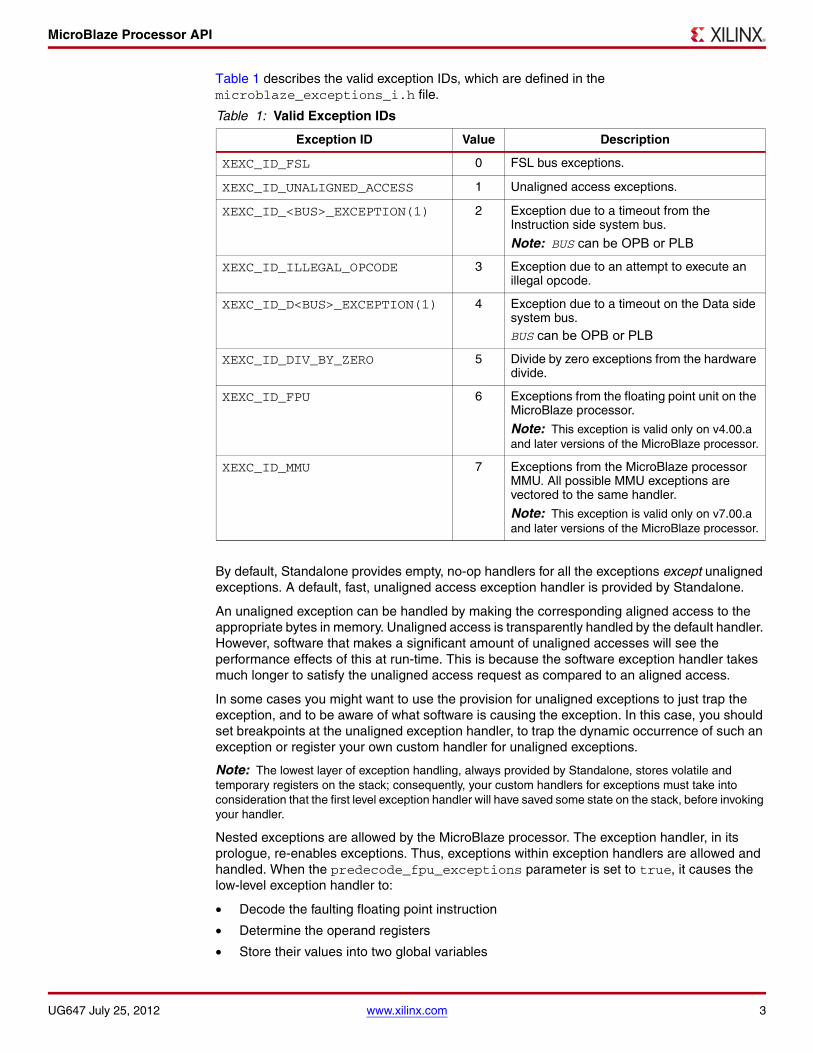
Table 1 describes the valid exception IDs, which are defined in the microblaze_exceptions_i.h file.
By default, Standalone provides empty, no-op handlers for all the exceptions except unaligned exceptions. A default, fast, unaligned access exception handler is provided by Standalone.
An unaligned exception can be handled by making the corresponding aligned access to the appropriate bytes in memory. Unaligned access is transparently handled by the default handler. However, software that makes a significant amount of unaligned accesses will see the performance effects of this at run-time. This is because the software exception handler takes much longer to satisfy the unaligned access request as compared to an aligned access.
In some cases you might want to use the provision for unaligned exceptions to just trap the exception, and to be aware of what software is causing the exception. In this case, you should set breakpoints at the unaligned exception handler, to trap the dynamic occurrence of such an exception or register your own custom handler for unaligned exceptions.
Note: The lowest layer of exception handling, always provided by Standalone, stores volatile and temporary registers on the stack; consequently, your custom handlers for exceptions must take into consideration that the first level exception handler will have saved some state on the stack, before invoking your handler.
Nested exceptions are allowed by the MicroBlaze processor. The exception handler, in its prologue, re-enables exceptions. Thus, exceptions within exception handlers are allowed and handled. When the predecode_fpu_exceptions parameter is set to true, it causes the low-level exception handler to:
• Decode the faulting floating point instruction
• Determine the operand registers
• Store their values into two global variables
Table 1: Valid Exception IDs
Exception ID Value Description
XEXC_ID_FSL 0 FSL bus exceptions.
XEXC_ID_UNALIGNED_ACCESS 1 Unaligned access exceptions.
XEXC_ID_<BUS>_EXCEPTION(1) 2 Exception due to a timeout from the Instruction side system bus.
Note: BUS can be OPB or PLB
XEXC_ID_ILLEGAL_OPCODE 3 Exception due to an attempt to execute an illegal opcode.
XEXC_ID_D<BUS>_EXCEPTION(1) 4 Exception due to a timeout on the Data side system bus.BUS can be OPB or PLB
XEXC_ID_DIV_BY_ZERO 5 Divide by zero exceptions from the hardware divide.
XEXC_ID_FPU 6 Exceptions from the floating point unit on the MicroBlaze processor.
Note: This exception is valid only on v4.00.a and later versions of the MicroBlaze processor.
XEXC_ID_MMU 7 Exceptions from the MicroBlaze processor MMU. All possible MMU exceptions are vectored to the same handler.
Note: This exception is valid only on v7.00.a and later versions of the MicroBlaze processor.
UG647 July 25, 2012 www.xilinx.com 3

MicroBlaze Processor API
You can register a handler for floating point exceptions and retrieve the values of the operands from the global variables. You can use the microblaze_getfpex_operand_a() and microblaze_getfpex_operand_b() macros.
Note: These macros return the operand values of the last floating point (FP) exception. If there are nested exceptions, you cannot retrieve the values of outer exceptions. An FP instruction might have one of the source registers being the same as the destination operand. In this case, the faulting instruction overwrites the input operand value and it is again irrecoverable.
MicroBlaze Processor Instruction Cache Handling
The following functions help manage instruction caches on the MicroBlaze processor. You must include the mb_interface.h header file in your source code to use these functions.
Note: These functions work correctly only when the parameters that determine the caching system are configured appropriately in the MicroBlaze Microprocessor Hardware Specification (MHS) hardware block. Refer to the MicroBlaze Reference Guide (UG081) for information on how to configure these cache parameters. “MicroBlaze Processor API,” page 1 contains a link to this document.
MicroBlaze Processor Instruction Cache Handling Function Descriptions
void microblaze_enable_icache(void)
Enable the instruction cache on the MicroBlaze processor. When the MicroBlaze processor starts up, the instruction cache is disabled. The instruction cache must be explicitly turned on using this function.
void microblaze_disable_icache(void)
Disable the instruction cache on the MicroBlaze processor.
void microblaze_invalidate_icache()
Invalidate the instruction icache.
Note: For MicroBlaze processors prior to version v7.20.a:The cache and interrupts are disabled before invalidation starts and restored to their previous state after invalidation.
void microblaze_invalidate_icache_range(unsigned int cache_addr, unsigned int cache_size)
Invalidate the specified range in the instruction icache. This function can be used for invalidating all or part of the instruction icache.
The parameter cache_addr indicates the beginning of the cache location to be invalidated. The cache_size represents the number of bytes from the cache_addr to invalidate.
Note that cache lines are invalidated starting from the cache line to which cache_addr belongs and ending at the cache line containing the address (cache_addr + cache_size - 1).
For example, microblaze_invalidate_icache_range (0x00000300, 0x100) invalidates the instruction cache region from 0x300 to 0x3ff (0x100 bytes of cache memory is cleared starting from 0x300).
Note: For MicroBlaze processors prior to version v7.20.a: The cache and interrupts are disabled before invalidation starts and restored to their previous state after invalidation.
4 www.xilinx.com UG647 July 25, 2012

MicroBlaze Processor API
MicroBlaze Processor Data Cache Handling
The following functions help manage data caches on the MicroBlaze processor. You must include the header file mb_interface.h in your source code to use these functions.
Note: These functions work correctly only when the parameters that determine the caching system are configured appropriately in the MicroBlaze MHS hardware block. Refer to the MicroBlaze Processor Reference Guide (UG081) for information on how to configure these cache parameters. “MicroBlaze Processor API,” page 1 contains a link to this document.
Data Cache Handling Functions
void microblaze_enable_dcache(void)
Enable the data cache on the MicroBlaze processor. When the MicroBlaze processor starts up, the data cache is disabled. The data cache must be explicitly turned on using this function.
void microblaze_disable_dcache(void)
Disable the data cache on the MicroBlaze processor. If writeback caches are enabled in the MicroBlaze processor hardware, this function also flushes the dirty data in the cache back to external memory and invalidates the cache. For write through caches, this function does not do any extra processing other than disabling the cache.
void microblaze_flush_dcache()
Flush the entire data cache. This function can be used when write-back caches are turned on in the MicroBlaze processor hardware. Executing this function ensures that the dirty data in the cache is written back to external memory and the contents invalidated.
• The cache is disabled before the flush starts and is restored to its previous state after the flush is complete.
• Interrupts are disabled while the cache is being flushed and restored to their previous state after the flush is complete.
void microblaze_flush_dcache_range(unsigned int cache_addr, unsigned int cache_len)
Flush the specified data cache range. This function can be used when write-back caches are enabled in the MicroBlaze processor hardware. Executing this function ensures that the dirty data in the cache range is written back to external memory and the contents of the cache range are invalidated. Note that cache lines will be flushed starting from the cache line to which cache_addr belongs and ending at the cache line containing the address (cache_addr + cache_size - 1).
For example, microblaze_flush_dcache_range (0x00000300, 0x100) flushes the data cache region from 0x300 to 0x3ff (0x100 bytes of cache memory is flushed starting from 0x300).
void microblaze_invalidate_dcache()
Invalidate the instruction data cache.
Note: For MicroBlaze processors prior to version v7.20.a:The cache and interrupts are disabled before invalidation starts and restored to their previous state after invalidation.
UG647 July 25, 2012 www.xilinx.com 5

MicroBlaze Processor API
void microblaze_invalidate_dcache_range(unsigned int cache_addr, unsigned int cache_size)
Invalidate the data cache. This function can be used for invalidating all or part of the data cache. The parameter cache_addr indicates the beginning of the cache location and cache_size represents the size from cache_addr to invalidate.
Note that cache lines will be invalidated starting from the cache line to which cache_addr belongs and ending at the cache line containing the address (cache_addr + cache_size - 1).
Note: For MicroBlaze processors prior to version v7.20.a:The cache and interrupts are disabled before invalidation starts and restored to their previous state after invalidation.
For example, microblaze_invalidate_dcache_range (0x00000300, 0x100) invalidates the data cache region from 0x300 to 0x3ff (0x100 bytes of cache memory is cleared starting from 0x300).
Software Sequence for Initializing Instruction and Data Caches
Typically, before using the cache, your program must perform a particular sequence of cache operations to ensure that invalid/dirty data in the cache is not being used by the processor. This would typically happen during repeated program downloads and executions.
The following example snippets show the necessary software sequence for initializing instruction and data caches in your program.
/* Initialize ICache *// microblaze_invalidate_icache(); microblaze_enable_icache ();
/* Initialize DCache */ microblaze_invalidate_dcache(); microblaze_enable_dcache ();
At the end of your program, you should also put in a sequence similar to the example snippet below. This ensures that the cache and external memory are left in a valid and clean state.
/* Clean up DCache. For writeback caches, the disable_dcache routine internally does the flush and invalidate. For write through caches,
an explicit invalidation must be performed on the entire cache. */
#if XPAR_MICROBLAZE_DCACHE_USE_WRITEBACK == 0microblaze_invalidate_dcache();#endif
microblaze_disable_dcache();
/* Clean up ICache */microblaze_invalidate_icache();microblaze_disable_icache();
MicroBlaze Processor Fast Simplex Link (FSL) Interface Macros
Standalone includes macros to provide convenient access to accelerators connected to the MicroBlaze Fast Simplex Link (FSL) Interfaces.
6 www.xilinx.com UG647 July 25, 2012

MicroBlaze Processor API
MicroBlaze Processor Fast Simplex Link (FSL) Interface Macro Summary
The following is a list of the available macros. Click on a macro name to go to the description of the active macros.
MicroBlaze Processor FSL Macro Descriptions
The following macros provide access to all of the functionality of the MicroBlaze FSL feature in one simple and parameterized interface. Some capabilities are available on MicroBlaze v7.00.a and later only, as noted in the descriptions.
In the macro descriptions, val refers to a variable in your program that can be the source or sink of the FSL operation.
Note: id must be an integer literal in the basic versions of the macro (getfslx, putfslx, tgetfslx, tputfslx) and can be an integer literal or an integer variable in the dynamic versions of the macros (getdfslx, putdfslx, tgetdfslx, tputdfslx.)
You must include fsl.h in your source files to make these macros available.
getfslx(val,id,flags)
Performs a get function on an input FSL of the MicroBlaze processor; id is the FSL identifier and is a literal in the range of 0 to 7 (0 to 15 for MicroBlaze v7.00.a and later). The semantics of the instruction is determined by the valid FSL macro flags, which are listed in Table 2, page 9.
putfslx(val,id,flags)
Performs a put function on an input FSL of the MicroBlaze processor; id is the FSL identifier and is a literal in the range of 0 to 7 (0 to 15 for MicroBlaze processor v7.00.a and later).
The semantics of the instruction is determined by the valid FSL macro flags, which are listed in Table 2, page 9.
tgetfslx(val,id,flags)
Performs a test get function on an input FSL of the MicroBlaze processor; id is the FSL identifier and is a literal in the ranging of 0 to 7 (0 to 15 for MicroBlaze v7.00.a and later). This macro can be used to test reading a single value from the FSL. The semantics of the instruction is determined by the valid FSL macro flags, which are listed in Table 2, page 9.
getfslx(val,id,flags)putfslx(val,id,flags)tgetfslx(val,id,flags)getd fslx(val,id,flags)
putdfslx(val,id,flags) tgetdfslx(val,id,flags) tputdfslx(val,id,flags) fsl_isinvalid(invalid) fsl_iserror(error)
UG647 July 25, 2012 www.xilinx.com 7

MicroBlaze Processor API
tputfslx(val,id,flags)
Performs a put function on an input FSL of the MicroBlaze processor; id is the FSL identifier and is a literal in the range of 0 to 7 (0 to 15 for MicroBlaze processor v7.00.a and later). This macro can be used to test writing a single value to the FSL.The semantics of the put instruction is determined by the valid FSL macro flags, which are listed in Table 2, page 9.
getd fslx(val,id,flags)
Performs a get function on an input FSL of the MicroBlaze processor; id is the FSL identifier and is an integer value or variable in the range of 0 to 15. The semantics of the instruction is determined by the valid FSL macro flags, which are listed in Table 2, page 9. This macro is available on MicroBlaze processor v7.00.a and later only.
putdfslx(val,id,flags)
Performs a put function on an input FSL of the MicroBlaze processor; id is the FSL identifier and is an integer value or variable in the range of 0 to 15. The semantics of the instruction is determined by the valid FSL macro flags, which are listed in Table 2, page 9. This macro is available on MicroBlaze processor v7.00.a and later only.
tgetdfslx(val,id,flags)
Performs a test get function on an input FSL of the MicroBlaze processor; id is the FSL identifier and is an integer or variable in the range of 0 to 15. This macro can be used to test reading a single value from the FSL. The semantics of the instruction is determined by the valid FSL macro flags, listed in Table 2. This macro is available on MicroBlaze processor v7.00.a and later only.
tputdfslx(val,id,flags)
Performs a put function on an input FSL of the MicroBlaze processor; id is the FSL identifier and is an integer or variable in the range of 0 to 15. This macro can be used to test writing a single value to the FSL.The semantics of the instruction is determined by the valid FSL macro flags, listed in Table 2. This macro is available on MicroBlaze processor v7.00.a and later only.
fsl_isinvalid(invalid)
Checks if the last FSL operation returned valid data. This macro is applicable after invoking a non-blocking FSL put or get instruction. If there was no data on the FSL channel on a get, or if the FSL channel was full on a put, invalid is set to 1; otherwise, it is set to 0.
fsl_iserror(error)
This macro is used to check if the last FSL operation set an error flag. This macro is applicable after invoking a control FSL put or get instruction. If the control bit was set error is set to 1; otherwise, it is set to 0.
8 www.xilinx.com UG647 July 25, 2012

MicroBlaze Processor API
MicroBlaze Processor FSL Macro Flags
Table 2 lists the available FSL Macro flags.
Deprecated MicroBlaze Processor Fast Simplex Link (FSL) Macros
The following macros are deprecated:
getfsl(val,id)(deprecated)
Performs a blocking data get function on an input FSL of the MicroBlaze processor; id is the FSL identifier in the range of 0 to 7. This macro is uninterruptible.
putfsl(val,id)(deprecated)
Performs a blocking data put function on an output FSL of the MicroBlaze processor; id is the FSL identifier in the range of 0 to 7. This macro is uninterruptible.
Table 2: FSL Macro Flags
Flag Description
FSL_DEFAULT Blocking semantics (on MicroBlaze processor v7.00.a and later this mode is interruptible).
FSL_NONBLOCKING Non-blocking semantics.1
1. When non-blocking semantics are not applied, blocking semantics are implied.
FSL_EXCEPTION Generate exceptions on control bit mismatch.2
2. This combination of flags is available only on MicroBlaze processor v7.00.a and later versions.
FSL_CONTROL Control semantics.
FSL_ATOMIC Atomic semantics.A sequence of FSL instructions cannot be interrupted.
FSL_NONBLOCKING_EXCEPTION Combines non-blocking and exception semantics.
FSL_NONBLOCKING_CONTROL Combines non-blocking and control semantics.
FSL_NONBLOCKING_ATOMIC Combines non-blocking and atomic semantics.
FSL_EXCEPTION_CONTROL Combines exception and control semantics.
FSL_EXCEPTION_ATOMIC Combines exception and atomic semantics.
FSL_CONTROL_ATOMIC Combines control and atomic semantics.
FSL_NONBLOCKING_EXCEPTION_CONTROL
Combines non-blocking, exception, and control semantics.2
FSL_NONBLOCKING_EXCEPTION_ATOMIC
Combines non-blocking, exception, and atomic semantics.
FSL_NONBLOCKING_CONTROL_ATOMIC
Combines non-blocking, atomic, and control semantics.
FSL_EXCEPTION_CONTROL_ATOMIC
Combines exception, atomic, and control semantics.
FSL_NONBLOCKING_EXCEPTION_CONTROL_ATOMIC
Combines non-blocking, exception, control, and atomic semantics.
UG647 July 25, 2012 www.xilinx.com 9

MicroBlaze Processor API
ngetfsl(val,id)(deprecated)
Performs a non-blocking data get function on an input FSL of the MicroBlaze processor; id is the FSL identifier in the range of 0 to 7.
nputfsl(val,id)(deprecated)
Performs a non-blocking data put function on an output FSL of the MicroBlaze processor; id is the FSL identifier in the range of 0 to 7.
cgetfsl(val, id)(deprecated)
Performs a blocking control get function on an input FSL of the MicroBlaze processor; id is the FSL identifier in the range of 0 to 7. This macro is uninterruptible.
cputfsl(val, id)(deprecated)
Performs a blocking control put function on an output FSL of the MicroBlaze processor; id is the FSL identifier in the range of 0 to 7. This macro is uninterruptible.
ncgetfsl(val, id)(deprecated)
Performs a non-blocking control get function on an input FSL of the MicroBlaze processor; id is the FSL identifier in the range of 0 to 7.
ncputfsl(val, id)(deprecated)
Performs a non-blocking control put function on an output FSL of the MicroBlaze processor; id is the FSL identifier in the range of 0 to 7.
getfsl_interruptible(val, id)(deprecated)
Performs repeated non-blocking data get operations on an input FSL of the MicroBlaze processor until valid data is actually fetched; id is the FSL identifier in the range of 0 to 7. Because the FSL access is non-blocking, interrupts will be serviced by the processor.
putfsl_interruptible(val, id)(deprecated)
Performs repeated non-blocking data put operations on an output FSL of the MicroBlaze processor until valid data is sent out; id is the FSL identifier in the range of 0 to 7. Because the FSL access is non-blocking, interrupts will be serviced by the processor.
10 www.xilinx.com UG647 July 25, 2012

MicroBlaze Processor API
cgetfsl_interruptible(val, id)(deprecated)
Performs repeated non-blocking control get operations on an input FSL of the MicroBlaze processor until valid data is actually fetched; id is the FSL identifier in the range of 0 to 7. Because the FSL access is non-blocking, interrupts are serviced by the processor.
cputfsl_interruptible(val, id)(deprecated)
Performs repeated non-blocking control put operations on an output FSL of the MicroBlaze processor until valid data is sent out; id is the FSL identifier in the range of 0 to 7. Because the FSL access is non-blocking, interrupts are serviced by the processor.
MicroBlaze Processor Pseudo-asm Macros
Standalone includes macros to provide convenient access to various registers in the MicroBlaze processor. Some of these macros are very useful within exception handlers for retrieving information about the exception. To use these macros, you must include the mb_interface.h header file in your source code.
MicroBlaze Processor Pseudo-asm Macro Summary
The following is a summary of the MicroBlaze processor pseudo-asm macros. Click on the macro name to go to the description.
MicroBlaze Processor Pseudo-asm Macro Descriptions
mfgpr(rn)
Return value from the general purpose register (GPR) rn.
mfmsr( )
Return the current value of the MSR.
mfesr( )
Return the current value of the Exception Status Register (ESR).
mfear( )
Return the current value of the Exception Address Register (EAR).
mfgpr(rn) mfmsr( ) mfesr( ) mfear( ) mtmsr(v) mtgpr(rn,v) microblaze_getfpex_operand_a( ) microblaze_getfpex_operand_b( )
UG647 July 25, 2012 www.xilinx.com 11

MicroBlaze Processor API
mffsr( )
Return the current value of the Floating Point Status (FPS).
mtmsr(v)
Move the value v to MSR.
mtgpr(rn,v)
Move the value v to GPR rn.
microblaze_getfpex_operand_a( )
Return the saved value of operand A of the last faulting floating point instruction.
microblaze_getfpex_operand_b( )
Return the saved value of operand B of the last faulting floating point instruction.
Note: Because of the way some of these macros have been written, they cannot be used as parameters to function calls and other such constructs.
MicroBlaze Processor Version Register (PVR) Access Routine and Macros
MicroBlaze processor v5.00.a and later versions have configurable Processor Version Registers (PVRs). The contents of the PVR are captured using the pvr_t data structure, which is defined as an array of 32-bit words, with each word corresponding to a PVR register on hardware. The number of PVR words is determined by the number of PVRs configured in the hardware. You should not attempt to access PVR registers that are not present in hardware, as the pvr_t data structure is resized to hold only as many PVRs as are present in hardware.
To access information in the PVR:
1. Use the microblaze_get_pvr() function to populate the PVR data into a pvr_t data structure.
2. In subsequent steps, you can use any one of the PVR access macros list to get individual data stored in the PVR.
Note: The PVR access macros take a parameter, which must be of type pvr_t.
PVR Access Routine
The following routine is used to access the PVR. You must include pvr.h file to make this routine available.
int_microblaze_get_pvr(pvr_t_*pvr)
Populate the PVR data structure to which pvr points with the values of the hardware PVR registers. This routine populates only as many PVRs as are present in hardware and the rest are zeroed. This routine is not available if C_PVR is set to NONE in hardware.
12 www.xilinx.com UG647 July 25, 2012

MicroBlaze Processor API
PVR Macros
The following processor macros are used to access the PVR. You must include pvr.h file to make these macros available.
Table 3 lists the MicroBlaze processor PVR macros and descriptions.
Table 3: PVR Access Macros
Macro Description
MICROBLAZE_PVR_IS_FULL(pvr) Return non-zero integer if PVR is of type FULL, 0 if basic.
MICROBLAZE_PVR_USE_BARREL(pvr) Return non-zero integer if hardware barrel shifter present.
MICROBLAZE_PVR_USE_DIV(pvr) Return non-zero integer if hardware divider present.
MICROBLAZE_PVR_USE_HW_MUL(pvr) Return non-zero integer if hardware multiplier present.
MICROBLAZE_PVR_USE_FPU(pvr) Return non-zero integer if hardware floating point unit (FPU) present.
MICROBLAZE_PVR_USE_FPU2(pvr) Return non-zero integer if hardware floating point conversion and square root instructions are present.
MICROBLAZE_PVR_USE_ICACHE(pvr) Return non-zero integer if I-cache present.
MICROBLAZE_PVR_USE_DCACHE(pvr) Return non-zero integer if D-cache present.
MICROBLAZE_PVR_MICROBLAZE_VERSION (pvr) Return MicroBlaze processor version encoding. Refer to the MicroBlaze Processor Reference Guide (UG081) for mappings from encodings to actual hardware versions. “MicroBlaze Processor API,” page 1 contains a link to this document.
MICROBLAZE_PVR_USER1(pvr) Return the USER1 field stored in the PVR.
MICROBLAZE_PVR_USER2(pvr) Return the USER2 field stored in the PVR.
MICROBLAZE_PVR_INTERCONNECT(pvr) Return non-zero if MicroBlaze processor has PLB interconnect; otherwise return zero.
MICROBLAZE_PVR_D_PLB(pvr) Return non-zero integer if Data Side PLB interface is present.
MICROBLAZE_PVR_D_OPB(pvr) Return non-zero integer if Data Side On-chip Peripheral Bus (OPB) interface present.
MICROBLAZE_PVR_D_LMB(pvr) Return non-zero integer if Data Side Local Memory Bus (LMB) interface present.
MICROBLAZE_PVR_I_PLB(pvr) Return non-zero integer if Instruction Side PLB interface is present.
MICROBLAZE_PVR_I_OPB(pvr) Return non-zero integer if Instruction side OPB interface present.
MICROBLAZE_PVR_I_LMB(pvr) Return non-zero integer if Instruction side LMB interface present.
MICROBLAZE_PVR_INTERRUPT_IS_EDGE(pvr)
Return non-zero integer if interrupts are configured as edge-triggered.
MICROBLAZE_PVR_EDGE_IS_POSITIVE(pvr) Return non-zero integer if interrupts are configured as positive edge triggered.
MICROBLAZE_PVR_USE_MUL64(pvr) Return non-zero integer if MicroBlaze processor supports 64-bit products for multiplies.
MICROBLAZE_PVR_OPCODE_OxO_ILLEGAL (pvr) Return non-zero integer if opcode 0x0 is treated as an illegal opcode.
UG647 July 25, 2012 www.xilinx.com 13

MicroBlaze Processor API
MICROBLAZE_PVR_UNALIGNED_EXCEPTION(pvr) Return non-zero integer if unaligned exceptions are supported.
MICROBLAZE_PVR_ILL_OPCODE_EXCEPTION(pvr) Return non-zero integer if illegal opcode exceptions are supported.
MICROBLAZE_PVR_IOPB_EXCEPTION(pvr) Return non-zero integer if I-OPB exceptions are supported.
MICROBLAZE_PVR_DOPB_EXCEPTION(pvr) Return non-zero integer if D-OPB exceptions are supported.
MICROBLAZE_PVR_IPLB_EXCEPTION(pvr) Return non-zero integer if I-PLB exceptions are supported.
MICROBLAZE_PVR_DPLB_EXCEPTION(pvr) Return non-zero integer if D-PLB exceptions are supported.
MICROBLAZE_PVR_DIV_ZERO_EXCEPTION(pvr) Return non-zero integer if divide by zero exceptions are supported.
MICROBLAZE_PVR_FPU_EXCEPTION(pvr) Return non-zero integer if FPU exceptions are supported.
MICROBLAZE_PVR_FSL_EXCEPTION(pvr) Return non-zero integer if FSL exceptions are present.
MICROBLAZE_PVR_DEBUG_ENABLED(pvr) Return non-zero integer if debug is enabled.
MICROBLAZE_PVR_NUM_PC_BRK(pvr) Return the number of hardware PC breakpoints available.
MICROBLAZE_PVR_NUM_RD_ADDR_BRK(pvr) Return the number of read address hardware watchpoints supported.
MICROBLAZE_PVR_NUM_WR_ADDR_BRK(pvr) Return the number of write address hardware watchpoints supported.
MICROBLAZE_PVR_FSL_LINKS(pvr) Return the number of FSL links present.
MICROBLAZE_PVR_ICACHE_BASEADDR(pvr) Return the base address of the I-cache.
MICROBLAZE_PVR_ICACHE_HIGHADDR(pvr) Return the high address of the I-cache.
MICROBLAZE_PVR_ICACHE_ADDR_TAG_BITS(pvr) Return the number of address tag bits for the I-cache.
MICROBLAZE_PVR_ICACHE_USE_FSL(pvr) Return non-zero if I-cache uses FSL links.
MICROBLAZE_PVR_ICACHE_ALLOW_WR(pvr) Return non-zero if writes to I-caches are allowed.
MICROBLAZE_PVR_ICACHE_LINE_LEN(pvr) Return the length of each I-cache line in bytes.
MICROBLAZE_PVR_ICACHE_BYTE_SIZE (pvr) Return the size of the D-cache in bytes.
MICROBLAZE_PVR_DCACHE_BASEADDR(pvr) Return the base address of the D-cache.
MICROBLAZE_PVR_DCACHE_HIGHADDR(pvr) Return the high address of the D-cache.
MICROBLAZE_PVR_DCACHE_ADDR_TAG_BITS(pvr) Return the number of address tag bits for the D-cache.
MICROBLAZE_PVR_DCACHE_USE_FSL(pvr) Return non-zero if the D-cache uses FSL links.
MICROBLAZE_PVR_DCACHE_ALLOW_WR(pvr) Return non-zero if writes to D-cache are allowed.
MICROBLAZE_PVR_DCACHE_LINE_LEN(pvr) Return the length of each line in the D-cache in bytes.
MICROBLAZE_PVR_DCACHE_BYTE_SIZE(pvr) Return the size of the D-cache in bytes.
MICROBLAZE_PVR_TARGET_FAMILY(pvr) Return the encoded target family identifier.
Table 3: PVR Access Macros (Cont’d)
Macro Description
14 www.xilinx.com UG647 July 25, 2012

PowerPC 405 Processor API
MicroBlaze Processor File Handling
The following routine is included for file handling:
int_fcntl(int fd, int cmd, long arg);
A dummy implementation of fcntl( ), which always returns 0, is provided. fcntl is intended to manipulate file descriptors according to the command specified by cmd. Because Standalone does not provide a file system, this function is included for completeness only.
MicroBlaze Processor Errno
The following routine provides the error number value:
int_errno( );
Return the global value of errno as set by the last C library call.
PowerPC 405 Processor API
Standalone for the PowerPC® 405 processor contains boot code, cache, file and memory management, configuration, exception handling, time and processor-specific include functions.
The following is a list of the PowerPC 405 processor API sections. To go the function description, click the function name in the summary.
• “PowerPC 405 Processor Boot Code”
• “PowerPC 405 Processor Cache Functions”
• “PowerPC 405 Processor Exception Handling Function Summary”
• “PowerPC 405 Processor Files”
• “PowerPC 405 Processor Errno”
• “PowerPC 405 Processor Memory Management”
• “PowerPC 405 Processing Functions”
• “PowerPC 405 Processor-Specific Include Files”
• “PowerPC 405 Processor Time Functions”
• “PowerPC 405 Processor Fast Simplex Link Interface Macros”
• “PowerPC 405 Processor Pseudo-asm Macro Summary”
• “PowerPC 405 Macros for APU FCM User-Defined Instructions”
MICROBLAZE_PVR_MSR_RESET_VALUE Refer to the MicroBlaze Processor Reference Guide (UG081) for mappings from encodings to target family name strings. “MicroBlaze Processor API,” page 1 contains a link to this document.
MICROBLAZE_PVR_MMU_TYPE(pvr) Returns the value of C_USE_MMU. Refer to the MicroBlaze Processor Reference Guide (UG081) for mappings from MMU type values to MMU function. “MicroBlaze Processor API,” page 1 contains a link to this document.
Table 3: PVR Access Macros (Cont’d)
Macro Description
UG647 July 25, 2012 www.xilinx.com 15

PowerPC 405 Processor API
PowerPC 405 Processor Boot Code
The boot.S file contains a minimal set of code for transferring control from the processor’s reset location to the start of the application. Code in the boot.S consists of the two sections boot and boot0. The boot section contains only one instruction that is labeled with _boot. During the link process, this instruction is mapped to the reset vector and the _boot label marks the application's entry point. The boot instruction is a jump to the _boot0 label. The _boot0 label must reside within a ±23-bit address space of the _boot label. It is defined in the boot0 section. The code in the boot0 section calculates the 32-bit address of the _start label and jumps to that address.
PowerPC 405 Processor Cache Functions
The xcache_l.c file and corresponding xcache_l.h include file provide access to the following cache and cache-related operations
PowerPC 405 Processor Cache Function Summary
The following are links to the function descriptions. Click on the name to go to that function.
PowerPC 405 Processor Cache Function Descriptions
void XCache_WriteCCR0(unsigned int val)
Writes an integer value to the CCR0 register. Below is a sample code sequence. Before writing to this register, the instruction cache must be enabled to prevent a lockup of the processor core. After writing the CCR0, the instruction cache can be disabled, if not needed.
XCache_EnableICache(0x80000000) /* enable instruction cache for first 128 MB memory region */XCache_WriteCCR0(0x2700E00) /* enable 8 word pre-fetching */XCache_DisableICache() /* disable instruction cache */
void XCache_EnableDCache(unsigned int regions)
Enables the data cache for a specific memory region. Each bit in the regions parameter represents 128 MB of memory.
A value of 0x80000000 enables the data cache for the first 128 MB of memory (0 - 0x07FFFFFF). A value of 0x1 enables the data cache for the last 128 MB of memory (0xF8000000 - 0xFFFFFFFF).
void XCache_DisableDCache(void)
Disables the data cache for all memory regions.
void XCache_WriteCCR0(unsigned int val) void XCache_EnableDCache(unsigned int regions) void XCache_DisableDCache(void) void XCache_FlushDCacheLine(unsigned int adr) void XCache_InvalidateDCacheLine(unsigned int adr) void XCache_FlushDCacheRange(unsigned int adr, unsigned len) void XCache_InvalidateDCacheRange(unsigned int adr, unsigned len) void XCache_StoreDCacheLine(unsigned int adr); void XCache_EnableICache(unsigned int regions); void XCache_DisableICache(void); void XCache_InvalidateICache(void); void XCache_InvalidateICacheLine(unsigned int adr)
16 www.xilinx.com UG647 July 25, 2012

PowerPC 405 Processor API
void XCache_FlushDCacheLine(unsigned int adr)
Flushes and invalidates the data cache line that contains the address specified by the adr parameter. A subsequent data access to this address results in a cache miss and a cache line refill.
void XCache_InvalidateDCacheLine(unsigned int adr)
Invalidates the data cache line that contains the address specified by the adr parameter. If the cache line is currently dirty, the modified contents are lost and are not written to system memory. A subsequent data access to this address results in a cache miss and a cache line refill.
void XCache_FlushDCacheRange(unsigned int adr, unsigned len)
Flushes and invalidates the data cache lines that are described by the address range starting from adr and len bytes long. A subsequent data access to any address in this range results in a cache miss and a cache line refill.
void XCache_InvalidateDCacheRange(unsigned int adr, unsigned len)
Invalidates the data cache lines that are described by the address range starting from adr and len bytes long. If a cache line is currently dirty, the modified contents are lost and are not written to system memory. A subsequent data access to any address in this range results in a cache miss and a cache line refill.
void XCache_StoreDCacheLine(unsigned int adr);
Stores in memory the data cache line that contains the address specified by the adr parameter. A subsequent data access to this address results in a cache hit if the address was already cached; otherwise, it results in a cache miss and cache line refill.
void XCache_EnableICache(unsigned int regions);
Enables the instruction cache for a specific memory region. Each bit in the regions parameter represents 128 MB of memory.
A value of 0x80000000 enables the instruction cache for the first 128 MB of memory (0 - 0x07FFFFFF). A value of 0x1 enables the instruction cache for the last 128 MB of memory (0xF8000000 - 0xFFFFFFFF).
void XCache_DisableICache(void);
Disables the instruction cache for all memory regions.
void XCache_InvalidateICache(void);
Invalidates the whole instruction cache. Subsequent instructions produce cache misses and cache line refills.
UG647 July 25, 2012 www.xilinx.com 17

PowerPC 405 Processor API
void XCache_InvalidateICacheLine(unsigned int adr)
Invalidates the instruction cache line that contains the address specified by the adr parameter. A subsequent instruction to this address produces a cache miss and a cache line refill.
PowerPC 405 Processor Exception Handling
An exception handling API is provided in Standalone. For an in-depth explanation on how exceptions and interrupts work on the PowerPC processor, refer to the chapter “Exceptions and Interrupts” in the PowerPC Processor Reference Guide (UG011). A link to this document is provided in “MicroBlaze Processor API,” page 1.
Note: Exception handlers do not automatically reset (disable) the wait state enable bit in the MSR when returning to user code. You can force exception handlers to reset the Wait-Enable bit to zero on return from all exceptions by compiling Standalone with the preprocessor symbol PPC405_RESET_WE_ON_RFI defined. You can add this to the compiler flags associated with the libraries. This pre-processor define turns the behavior on.
The exception handling API consists of a set of the files xvectors.S, xexception_l.c, and the corresponding header file xexception_l.h.
For additional information on interrupt handing, refer to the “Interrupt Management” appendix in the Embedded System Tools Reference Manual (UG111), available in the /doc directory of your EDK installation.
PowerPC 405 Processor Exception Handling Function Summary
The following are links to the function descriptions. Click on the name to go to that function.
PowerPC 405 Processor Exception Handling Function Descriptions
void XExc_Init(void)
Sets up the interrupt vector table and registers a “do nothing” function for each exception. This function has no parameters and does not return a value.
This function must be called before registering any exception handlers or enabling any interrupts. When using the exception handler API, this function should be called at the beginning of your main( ) routine.
IMPORTANT: If you are not using the default linker script, you need to reserve memory space for storing the vector table in your linker script. The memory space must begin on a 64 k boundary.
The linker script entry should look like this example:
.vectors : { . = ALIGN(64k); *(.vectors) }
For further information on linker scripts, refer to the Linker documentation.
void XExc_Init(void) void XExc_RegisterHandler(Xuint8 ExceptionId,XExceptionHandler Handler, void *DataPtr) void XExc_RemoveHandler(Xuint8 ExceptionId) void XExc_mEnableExceptions (EnableMask) void XExc_mDisableExceptions (DisableMask)
18 www.xilinx.com UG647 July 25, 2012

PowerPC 405 Processor API
void XExc_RegisterHandler(Xuint8 ExceptionId,XExceptionHandler Handler, void *DataPtr)
Registers an exception handler for a specific exception; does not return a value. Refer to the following table for a list of exception types and their values.
The parameters are:
• ExceptionId is of parameter type Xuint8, and is the exception to which this handler should be registered. The type and the values are defined in the xexception_l.h header file. The following table lists the exception types and possible values.
• Handler is an XExceptionHandler parameter which is the pointer to the exception handling function.
• DataPtr is of parameter type void * and is the user value to be passed when the handling function is called.
The function provided as the Handler parameter must have the following function prototype:
typedef void (*XExceptionHandler)(void * DataPtr);
This prototype is declared in the xexception_l.h header file.
When this exception handler function is called, the parameter DataPtr contains the same value as you provided when you registered the handler.
void XExc_RemoveHandler(Xuint8 ExceptionId)
De-register a handler function for a given exception. For possible values of parameter ExceptionId, refer to Table 7, page 37.
Table 4: Registered Exception Types and Values
Exception Type Value
XEXC_ID_MACHINE_CHECK 1
XEXC_ID_CRITICAL_INT 2
XEXC_ID_DATA_STORAGE_INT 3
XEXC_ID_INSTRUCTION_STORAGE_INT 4
XEXC_ID_NON_CRITICAL_INT 5
XEXC_ID_ALIGNMENT_INT 6
XEXC_ID_PROGRAM_INT 7
XEXC_ID_FPU_UNAVAILABLE_INT 8
XEXC_ID_SYSTEM_CALL 9
XEXC_ID_APU_AVAILABLE 10
XEXC_ID_PIT_INT 11
XEXC_ID_FIT_INT 12
XEXC_ID_WATCHDOG_TIMER_INT 13
XEXC_ID_DATA_TLB_MISS_INT 14
XEXC_ID_INSTRUCTION_TLB_MISS_INT 15
XEXC_ID_DEBUG_INT 16
UG647 July 25, 2012 www.xilinx.com 19

PowerPC 405 Processor API
void XExc_mEnableExceptions (EnableMask)
Enable exceptions. This macro must be called after initializing the vector table with function exception_Init and registering exception handlers with function XExc_RegisterHandler. The parameter EnableMask is a bitmask for exceptions to be enabled. The EnableMask parameter can have the values XEXC_CRITICAL, XEXC_NON_CRITICAL, or XEXC_ALL.
void XExc_mDisableExceptions (DisableMask)
Disable exceptions. The parameter DisableMask is a bitmask for exceptions to be disabled.The DisableMask parameter can have the values XEXC_CRITICAL, XEXC_NON_CRITICAL, or XEXC_ALL.
PowerPC 405 Processor Files
File support is limited to the stdin and stdout streams; consequently, the following functions are not necessary:
• open() (in open.c)
• close() (in close.c)
• fstat() (in fstat.c)
• unlink() (in unlink.c)
• lseek() (in lseek.c)
These files are included for completeness and because they are referenced by the C library.
int read(int fd, char *buf, int nbytes)
The read() function in read.c reads nbytes bytes from the standard input by calling inbyte(). It blocks until all characters are available, or the end of line character is read. The read() function returns the number of characters read. The fd parameter is ignored.
int write(int fd, char *buf, int nbytes)
Writes nbytes bytes to the standard output by calling outbyte(). It blocks until all characters have been written. The write() function returns the number of characters written. The fd parameter is ignored.
int isatty(int fd)
Reports if a file is connected to a tty. This function always returns 1, Because only the stdin and stdout streams are supported.
int fcntl(int fd, int cmd, long arg);
A dummy implementation of fcntl, which always returns 0. fcntl is intended to manipulate file descriptors according to the command specified by cmd. Because Standalone does not provide a file system, this function is not used.
20 www.xilinx.com UG647 July 25, 2012
PowerPC 405 Processor API
PowerPC 405 Processor Errno
int errno()
Returns the global value of errno as set by the last C library call.
PowerPC 405 Processor Memory Management
char *sbrk(int nbytes)
Allocates nbytes of heap and returns a pointer to that piece of memory. This function is called from the memory allocation functions of the C library.
PowerPC 405 Processing Functions
The functions getpid( ) in getpid.c and kill( ) in kill.c are included for completeness and because they are referenced by the C library.
PowerPC 405 Processor-Specific Include Files
The xreg405.h include file contains the register numbers and the register bits for the PowerPC 405 processor.
The xpseudo-asm.h include file contains the definitions for the most often used inline assembler instructions, available as macros. These can be very useful for tasks such as setting or getting special purpose registers, synchronization, or cache manipulation.
These inline assembler instructions can be used from drivers and user applications written in C.
PowerPC 405 Processor Time Functions
The xtime_l.c file and corresponding xtime_l.h include file provide access to the 64-bit time base counter inside the PowerPC core. The counter increases by one at every processor cycle.
The sleep.c file and corresponding sleep.h include file implement sleep functions. Sleep functions are implemented as busy loops
UG647 July 25, 2012 www.xilinx.com 21

PowerPC 405 Processor API
PowerPC 405 Processor Time Function Summary
The following are links to the function descriptions. Click on the name to go to that function.
PowerPC 405 Processor Time Function Descriptions
typedef unsigned long long XTime
The XTime type in xtime_l.h represents the Time Base register. This struct consists of the Time Base Low (TBL) and Time Base High (TBH) registers, each of which is a 32-bit wide register.
The definition of XTime is as follows:
typedef unsigned long long XTime;
void XTime_SetTime(XTime xtime)
Sets the time base register to the value in xtime.
typedef unsigned long long XTime void XTime_SetTime(XTime xtime) void XTime_GetTime(XTime *xtime) void XTime_TSRClearStatusBits(unsigned long Bitmask) void XTime_PITSetInterval(unsigned long interval) void XTime_PITEnableInterrupt(void) void XTime_PITDisableInterrupt(void) void XTime_PITEnableAutoReload(void) void XTime_PITDisableAutoReload(void) void XTime_PITClearInterrupt(void) void XTime_FITEnableInterrupt(void) void XTime_FITDisableInterrupt(void) void XTime_FITClearInterrupt(void) void XTime_FITSetPeriod(unsigned long Period) void XTime_WDTEnableInterrupt(void) void XTime_WDTDisableInterrupt(void) void XTime_WDTClearInterrupt(void) void XTime_WDTSetPeriod(unsigned long Period) void XTime_WDTResetControl(unsigned long ControlVal) void XTime_WDTEnableNextWatchdog(void) void XTime_WDTClearResetStatus(void) unsigned int usleep(unsigned int _useconds) unsigned int sleep(unsigned int _seconds) int nanosleep(const struct timespec *rqtp, struct timespec *rmtp)
22 www.xilinx.com UG647 July 25, 2012

PowerPC 405 Processor API
void XTime_GetTime(XTime *xtime)
Writes the current value of the time base register to variable xtime.
void XTime_TSRClearStatusBits(unsigned long Bitmask)
Clears bits in the Timer Status Register (TSR). The parameter Bitmask designates the bits to be cleared. A value of 1 in any position of the Bitmask parameter clears the corresponding bit in the TSR. This function does not return a value.
Example:
XTime_TSRClearStatusBits(TSR_CLEAR_ALL);
Table 5 contains the values for the Bitmask parameters which are specified in the xreg405.h header file.
void XTime_PITSetInterval(unsigned long interval)
Loads a new value into the Programmable-Interval Timer Register. This register is a 32-bit decrementing counter clocked at the same frequency as the time-base register. Depending on the AutoReload setting the PIT is automatically reloaded with the last written value or must be reloaded manually. This function does not return a value.
Example:
XTime_PITSetInterval(0x00ffffff);
Table 5: Bitmask Parameter Values
Name Value Description
XREG_TSR_WDT_ENABLE_NEXT_WATCHDOG 0x80000000 Clearing this bit disables the watchdog timer event
XREG_TSR_WDT_INTERRUPT_STATUS 0x40000000 Clears the Watchdog Timer Interrupt Status bit. This bit is set after a watchdog interrupt occurs
XREG_TSR_WDT_RESET_STATUS_11 0x30000000 Clears the Watchdog Timer Reset Status bits. These bits specify the type of reset that occurred as a result of a watchdog timer event
XREG_TSR_PIT_INTERRUPT_STATUS 0x08000000 Clears the Programmable Interval Timer (PIT) Status bit. This bit is set after a PIT interrupt occurrence
XREG_TSR_FIT_INTERRUPT_STATUS 0x04000000 Clears the Fixed Interval Timer Status (FIT) bit. This bit is set after a FIT interrupt has occurred
XREG_TSR_CLEAR_ALL 0xFFFFFFFF Clears all bits in the TSR. After a Reset, the content of the TSR is not specified. Use this Bitmask to clear all bits in the TSR
UG647 July 25, 2012 www.xilinx.com 23

PowerPC 405 Processor API
void XTime_PITEnableInterrupt(void)
Enables the generation of PIT interrupts. An interrupt occurs when the PIT register contains a value of 1, and is then decremented. This function does not return a value. XExc_Init( ) must be called, the PIT interrupt handler must be registered, and exceptions must be enabled before calling this function.
Example:
XTime_PITEnableInterrupt();
void XTime_PITDisableInterrupt(void)
Disables the generation of PIT interrupts. It does not return a value.
Example:
XTime_PITDisableInterrupt();
void XTime_PITEnableAutoReload(void)
Enables the auto-reload function of the PIT Register. When auto-reload is enabled the PIT Register is automatically reloaded with the last value loaded by calling the XTime_PITSetInterval( ) function when the PIT Register contains a value of 1 and is decremented. When auto-reload is enabled, the PIT Register never contains a value of 0. This function does not return a value.
Example:
XTime_PITEnableAutoReload();
void XTime_PITDisableAutoReload(void)
Disables the auto-reload feature of the PIT Register. When auto-reload is disabled the PIT decrements from 1 to 0. If it contains a value of 0 it stops decrementing until it is loaded with a non-zero value. This function does not return a value.
Example:
XTime_PITDisableAutoReload();
void XTime_PITClearInterrupt(void)
Clears PIT-Interrupt-Status bit in the Timer-Status Register. This bit specifies whether a PIT interrupt occurred. You must call this function in your interrupt-handler to clear the Status bit, otherwise another PIT interrupt occurs immediately after exiting the interrupt handler function. This function does not return a value. Calling this function is equivalent to calling XTime_TSRClearStatusBits(XREG_TSR_PIT_INTERRUPT_STATUS).
Example:
XTime_PITClearInterrupt();
24 www.xilinx.com UG647 July 25, 2012

PowerPC 405 Processor API
void XTime_FITEnableInterrupt(void)
Enable Fixed Interval Timer (FIT) interrupts.
Example:
XTime_FITEnableInterrupt();
void XTime_FITDisableInterrupt(void)
Disable Fixed Interval Timer (FIT) interrupts.
Example:
XTime_FITDisableInterrupt();
void XTime_FITClearInterrupt(void)
Clear Fixed Interval Timer (FIT) interrupt status bit.This function is equivalent to calling XTime_TSRClearStatusBits(XREG_TSR_FIT_INTERRUPT_STATUS).
Example:
XTime_FITDisableInterrupt();
void XTime_FITSetPeriod(unsigned long Period)
Set the Fixed Interval Timer (FIT) Period value. This value can be one of the following:
• XREG_TCR_FIT_PERIOD_11 (2^21 clocks)
• XREG_TCR_FIT_PERIOD_10 (2^17 clocks)
• XREG_TCR_FIT_PERIOD_01 (2^13 clocks)
• XREG_TCR_FIT_PERIOD_00 (2^9 clocks)
These values are defined in xreg405.h
Example:
XTime_FITSetPeriod(XREG_TCR_FIT_PERIOD_11);
void XTime_WDTEnableInterrupt(void)
Enable Watchdog Timer (WDT) interrupts.
Example:
XTime_WDTEnableInterrupt();
void XTime_WDTDisableInterrupt(void)
Disable Watchdog Timer (WDT) interrupts.
Example:
XTime_WDTDisableInterrupt();
UG647 July 25, 2012 www.xilinx.com 25

PowerPC 405 Processor API
void XTime_WDTClearInterrupt(void)
Clear Watchdog Timer (WDT) interrupt status bit. Calling this function is equivalent to calling XTime_TSRClearStatusBits(XREG_TSR_WDT_INTERRUPT_STATUS).
Example:
XTime_WDTClearInterrupt();
void XTime_WDTSetPeriod(unsigned long Period)
Set the period for a Watchdog Timer (WDT) event.
Example:
XTime_WDTSetPeriod(0x10000);
void XTime_WDTResetControl(unsigned long ControlVal)
Specify the type of reset that occurs as a result of a Watchdog Timer (WDT) event.
The control value may be one of the following:
• XREG_WDT_RESET_CONTROL_11 (System reset)
• XREG_WDT_RESET_CONTROL_10 (Chip reset)
• XREG_WDT_RESET_CONTROL_01 (processor reset)
• XREG_WDT_RESET_CONTROL_00 (no reset)
These values are defined in xreg405.h
Example:
XTime_WDTResetControl (XREG_WDT_RESET_CONTROL_11);
void XTime_WDTEnableNextWatchdog(void)
Enables Watchdog Timer (WDT) event.
Example:
XTime_WDTEnableNextWatchdog ();
void XTime_WDTClearResetStatus(void)
Clear Watchdog Timer (WDT) reset status bits.
Example:
XTime_WDTClearResetStatus ();
26 www.xilinx.com UG647 July 25, 2012

PowerPC 405 Processor API
unsigned int usleep(unsigned int _useconds)
Delays the execution of a program by __useconds microseconds. It always returns zero. This function requires that the processor frequency (in Hz) is defined. The default value of this variable is 400 MHz. This value can be overwritten in the Microprocessor Software Specification (MSS) file as follows:
BEGIN PROCESSORPARAMETER HW_INSTANCE = PPC405_iPARAMETER DRIVER_NAME = cpu_ppc405PARAMETER DRIVER_VER = 1.00.aPARAMETER CORE_CLOCK_FREQ_HZ = 20000000END
The xparameters.h file can be modified with the correct value also, as follows:
#define XPAR_CPU_PPC405_CORE_CLOCK_FREQ_HZ 20000000
unsigned int sleep(unsigned int _seconds)
Delays the execution of a program by what is specified in _seconds. It always returns zero.This function requires that the processor frequency (in Hz) is defined. The default value of this variable is 400 MHz. This value can be overwritten in the Microprocessor Software Specification (MSS) file as follows:
BEGIN PROCESSORPARAMETER HW_INSTANCE = PPC405_iPARAMETER DRIVER_NAME = cpu_ppc405PARAMETER DRIVER_VER = 1.00.aPARAMETER CORE_CLOCK_FREQ_HZ = 20000000END
The file xparameters.h can also be modified with the correct value, as follows:
#define XPAR_CPU_PPC405_CORE_CLOCK_FREQ_HZ 20000000
int nanosleep(const struct timespec *rqtp, struct timespec *rmtp)
The nanosleep( ) function in sleep.c is not implemented. It is a placeholder for linking applications against the C library, and returns zero.
PowerPC 405 Processor Fast Simplex Link Interface Macros
Standalone includes macros to provide convenient access to accelerators connected to the PowerPC 405 processor Auxiliary Processing Unit (APU) over the FSL interfaces.
PowerPC 405 Processor Fast Simplex Link Interface Macro Summary
The following is a linked list the macros; click on a macro name to go to the description.
getfsl(val, id) putfsl(val, id) ngetfsl(val, id) nputfsl(val, id) cgetfsl(val, id) cputfsl(val, id) ncgetfsl(val, id)
ncputfsl(val, id) getfsl_interruptible(val, id) putfsl_interruptible(val, id) cgetfsl_interruptible(val, id) cputfsl_interruptible(val, id) fsl_isinvalid(invalid) fsl_iserror(error)
UG647 July 25, 2012 www.xilinx.com 27

PowerPC 405 Processor API
PowerPC 405 Processor FSL Interface Macro Descriptions
In the macros, val refers to a variable in your program that can be the source or sink of the FSL operation. You must include the fsl.h header file in your source files to make these macros available.
getfsl(val, id)
Performs a blocking data get function on an input FSL interface; id is the FSL identifier in the range of 0 to 31. This macro is interruptible.
putfsl(val, id)
Performs a blocking data put function on an output FSL interface; id is the FSL identifier in the range of 0 to 31. This macro is interruptible.
ngetfsl(val, id)
Performs a non-blocking data get function on an input FSL interface; id is the FSL identifier in the range of 0 to 31.
nputfsl(val, id)
Performs a non-blocking data put function on an output FSL interface; id is the FSL identifier in the range of 0 to 31.
cgetfsl(val, id)
Performs a blocking control get function on an input FSL interface; id is the FSL identifier in the range of 0 to 31. This macro is interruptible.
cputfsl(val, id)
Performs a blocking control put function on an output FSL interface; id is the FSL identifier in the range of 0 to 31. This macro is interruptible.
ncgetfsl(val, id)
Performs a non-blocking control get function on an input FSL interface; id is the FSL identifier in the range of 0 to 31.
ncputfsl(val, id)
This macro performs a non-blocking data control function on an output FSL interface; id is the FSL identifier in the range of 0 to 31.
getfsl_interruptible(val, id)
This macro is aliased to getfsl(val,id).
28 www.xilinx.com UG647 July 25, 2012

PowerPC 405 Processor API
putfsl_interruptible(val, id)
This macro is aliased to putfsl(val,id).
cgetfsl_interruptible(val, id)
This macro is aliased to cgetfsl(val,id).
cputfsl_interruptible(val, id)
This macro is aliased to cputfsl(val,id).
fsl_isinvalid(invalid)
Checks to determine if the last FSL operation returned valid data. This macro is applicable after invoking a non-blocking FSL put or get instruction. If there was no data on the FSL channel on a get, or if the FSL channel was full on a put, then invalid is set to 1; otherwise, invalid is set to 0.
fsl_iserror(error)
Checks to determine if the last FSL operation set an error flag. This macro is applicable after invoking a control FSL put or get instruction. If the control bit was set error is set to 1; otherwise, it is set to 0.
PowerPC 405 Processor Pseudo-asm Macro
Standalone includes macros to provide convenient access to various registers on the PowerPC 405 processor. You must include the header file xpseudo_asm.h in your source code to use these APIs.
PowerPC 405 Processor Pseudo-asm Macro SummaryThe following is a linked list of the Pseudo-asm Macros; click on a macro name to go to the description.
PowerPC 405 Processor Pseudo-asm Macro Descriptions
mfgpr(rn)
Return value from GPR rn.
mfgpr(rn) mfspr(rn) mfmsr( ) mfdcr(rn) mtdcr(rn,v) mtevpr(addr) mtspr(rn,v) mtgpr(rn,v) iccci
icbi(adr) icbt(adr) isync dccci(adr) dcbi(adr) dcbst(adr) dcbf(adr) dcread(adr) eieio sync
lbz(adr) lhz(adr) lwz(adr) stb(adr,val) sth(adr,val) stw(adr,val) lhbrx(adr) lwbrx(adr) sthbrx(adr,val) stwbrx(adr,val)
UG647 July 25, 2012 www.xilinx.com 29

PowerPC 405 Processor API
mfspr(rn)
Return the current value of the special purpose register (SPR) rn.
mfmsr( )
Return value from MSR.
mfdcr(rn)
Return value from the device control register (DCR) rn.
mtdcr(rn,v)
Move the value v to DCR rn.
mtevpr(addr)
Move the value addr to the exception vector prefix register (EVPR).
mtspr(rn,v)
Move the value v to SPR rn.
mtgpr(rn,v)
Move the value v to GPR rn.
iccci
Invalidate the instruction cache congruence class (entire cache).
icbi(adr)
Invalidate the instruction cache block at effective address adr.
icbt(adr)
Touch the instruction cache block at effective address adr.
isync
Execute the isync instruction.
dccci(adr)
Invalidate the data cache congruence class represented by effective address adr.
dcbi(adr)
Invalidate the data cache block at effective address adr.
30 www.xilinx.com UG647 July 25, 2012

PowerPC 405 Processor API
dcbst(adr)
Store the data cache block at effective address adr.
dcbf(adr)
Flush the data cache block at effective address adr.
dcread(adr)
Read from data cache address adr.
eieio
Execute the eieio instruction.
sync
Execute the sync instruction.
lbz(adr)
Execute a load and return the byte value from address adr.
lhz(adr)
Execute a load and return the word half-word value from address adr.
lwz(adr)
Execute a load and return the word value from address adr.
stb(adr,val)
Store the byte value in val into address adr.
sth(adr,val)
Store the half-word value in val into address adr.
stw(adr,val)
Store the word value in val into address adr.
lhbrx(adr)
Execute a Load Halfword Byte-Reversed Indexed instruction on effective address adr and return the value.
UG647 July 25, 2012 www.xilinx.com 31

PowerPC 405 Processor API
lwbrx(adr)
Execute a Load Word Byte-Reversed Indexed instruction on effective address adr and return the value.
sthbrx(adr,val)
Execute a Store Halfword Byte-Reversed Indexed instruction on effective address adr, on value val.
stwbrx(adr,val)
Execute a Store Word Byte-Reversed Indexed instruction on effective address adr, on value val.
PowerPC 405 Macros for APU FCM User-Defined Instructions
Macros are provided for using the user-defined instructions supported by the PowerPC 405 APU Fabric Coprocessor Module (FCM). There are a total of 16 user-defined instruction mnemonics provided: eight for instructions that modify the Condition Register (CR) and eight for the instructions that do not modify the CR. Because the meaning of the operands that these instructions take can be dynamically redefined, macros are provided for all combinations of operands. The user program must use the macros appropriately, in conjunction with higher level program flow.
UDI<n>FCM(a, b, c, fmt)
Inserts the mnemonic for user-defined fcm instruction n (that does not modify CR) into the user program. The user defined instruction, has a, b, c as operands to it in that order. The way the operands are interpreted by the compiler, is determined by the format specifier given by fmt. The format specifier is explained further below. n can range from 0 to 7. The mnemonic inserted is, udi<n>fcm.
UDI<n>FCMCR(a, b, c, fmt)
Inserts the mnemonic for user-defined fcm instruction (that modifies CR) n into the user program. The user-defined instruction has a, b, c as operands to it in that order. The way the operands are interpreted by the compiler, is determined by the format specifier fmt. Table 6 lists the format specifier identifiers and descriptions. The value for <n> has a range of 0 to 7. The mnemonic syntax is udi<n>fcm. (note the period at the end).
Table 6: Format Specifier for UDI Instructions
Identifier Meaning
FMT_GPR_GPR_GPR Operands a, b, and c are general purpose registers
FMT_GPR_GPR_IMM Operands a and b are general purpose registers. Operand c is an immediate value representing an immediate constant or an FCM register
FMT_GPR_IMM_IMM Operand a is a general purpose register. Operands b and c are immediate values representing an immediate constant or an FCM register
FMT_IMM_GPR_GPR Operands b and c are general purpose registers.Operand a is an immediate value representing an immediate constant or an FCM register.
32 www.xilinx.com UG647 July 25, 2012
PowerPC 440 Processor API
PowerPC 440 Processor API
Standalone contains boot code, cache, file and memory management, configuration, exception handling, time and processor-specific include functions.
The following lists the PowerPC 440 processor API sections. To go to a function section, click the name.
• PowerPC 440 Processor Boot Code
• PowerPC 440 Processor Cache Functions
• PowerPC 440 Processor Exception Handling
• PowerPC 440 Processor Errno Function
• PowerPC 440 Processor Memory Management
• PowerPC 440 Process Functions
• PowerPC 440 Processor-Specific Include Files
• PowerPC 440 Processor Time Functions
The following subsections describe the PowerPC 440 processor functions by type.
PowerPC 440 Processor Boot Code
The boot.S file contains a minimal set of code for transferring control from the processor’s reset location to the start of the application. Code in the boot.S consists of the two sections boot and boot0.
The boot section contains only one instruction that is labeled with _boot. During the link process, this instruction is mapped to the reset vector and the _boot label marks the entry point of the application. The boot instruction is a jump to the _boot0 label, and it is defined in the boot0 section.
Upon reset of the 440 core, only the 4 kB program memory page, located at the end of the 32-bit effective address space (which starts at 0xFFFFF000), is mapped into the MMU of the processor.
The .boot0 section contains instructions that initialize the TLBs in the MMU such that the entire 4 GB address space is mapped transparently for both I and D side:
• The I-side TLB entries have address space identifier set to 0.
• The D-side TLB entries have address space identifier set to 1.
The .boot0 section is located at address 0xFFFFFF00 which is within the initially mapped region of memory.
Apart from mapping TLBs, the code in boot0 also invalidates the I and D caches. Other core registers such as CCR01, CCR1, and MSR are initialized. MSR[DS] is set to 1 to partition data side translations to address space 1. Finally, the code in the boot0 section calculates the 32-bit address of the _start label and jumps to that address.
FMT_IMM_IMM_GPR Operand c is a general purpose register.Operands a and b are immediate values representing an immediate constant or an FCM register.
FMT_IMM_IMM_IMM All three operands are immediate values representing an immediate constant or an FCM register.
Table 6: Format Specifier for UDI Instructions (Cont’d)
Identifier Meaning
UG647 July 25, 2012 www.xilinx.com 33

PowerPC 440 Processor API
PowerPC 440 Processor Cache Functions
The xcache_l.c file and the corresponding xcache_l.h include file provide access to the following cache and cache-related operations.
PowerPC 440 Processor Cache Function Summary
The following are links to the function descriptions. Click on the name to go to that function.
PowerPC 440 Processor Cache Function Descriptions
void XCache_WriteCCR0(unsigned int val)
Writes an integer value to the CCR0 register. Below is a sample code sequence. Before writing to this register, the instruction cache must be enabled to prevent a lockup of the processor core. After writing the CCR0, the instruction cache can be disabled, if not needed.
XCache_EnableICache(0x80000000) /* enable instruction cache for first 256 MB memory region */XCache_WriteCCR0(0x00100000) /* Disable APU instruction broadcast */XCache_DisableICache() /* disable instruction cache */
void XCache_EnableDCache(unsigned int regions)
Enables the data cache for a specific memory region. Each pair of adjacent bits in the regions parameter represents 256 MB of memory. Setting either bit in the pair to 1 will enable caching for a particular 256 MB memory region.
For example:
• A value of 0x80000000 or 0x40000000 or 0xC0000000 enables the data cache for the first 256 MB of memory (0 - 0x07FFFFFF).
• A value of 0x1 or 0x2 or 0x3 enables the data cache for the last 256 MB of memory (0xF0000000 - 0xFFFFFFFF).
Note: if you are migrating software from a PowerPC 405 processor design, be aware that each bit enables 128 MB more of memory for caching.
void XCache_DisableDCache(void)
Disables the data cache for all memory regions.
void XCache_WriteCCR0(unsigned int val) void XCache_EnableDCache(unsigned int regions) void XCache_DisableDCache(void) void XCache_FlushDCacheLine(unsigned int adr) void XCache_InvalidateDCacheLine(unsigned int adr) void XCache_FlushDCacheRange(unsigned int adr, unsigned len) void XCache_InvalidateDCacheRange(unsigned int adr, unsigned len) void XCache_StoreDCacheLine(unsigned int adr) void XCache_EnableICache(unsigned int regions) void XCache_DisableICache(void) void XCache_InvalidateICache(void) void XCache_InvalidateICacheLine(unsigned int adr) void XCache_TouchICacheBlock(unsigned int adr)
34 www.xilinx.com UG647 July 25, 2012

PowerPC 440 Processor API
void XCache_FlushDCacheLine(unsigned int adr)
Flushes and invalidates the data cache line that contains the address specified by the adr parameter. A subsequent data access to this address results in a cache miss and a cache line refill.
void XCache_InvalidateDCacheLine(unsigned int adr)
Invalidates the data cache line that contains the address specified by the adr parameter. If the cache line is currently dirty, the modified contents are lost and are not written to system memory. A subsequent data access to this address results in a cache miss and a cache line refill.
void XCache_FlushDCacheRange(unsigned int adr, unsigned len)
Flushes and invalidates the data cache lines that are described by the address range starting from adr and len bytes long. A subsequent data access to any address in this range results in a cache miss and a cache line refill.
void XCache_InvalidateDCacheRange(unsigned int adr, unsigned len)
Invalidates the data cache lines that are described by the address range starting from adr and len bytes long. If a cache line is currently dirty, the modified contents are lost and are not written to system memory. A subsequent data access to any address in this range results in a cache miss and a cache line refill.
void XCache_StoreDCacheLine(unsigned int adr)
Stores in memory the data cache line that contains the address specified by the adr parameter. A subsequent data access to this address results in a cache hit if the address was already cached; otherwise, it results in a cache miss and cache line refill.
void XCache_EnableICache(unsigned int regions)
Enables the instruction cache for a specific memory region. Each pair of adjacent bits in the regions parameter represents 256 MB of memory. Setting either bit in the pair to 1 will enable caching for a particular 256 MB memory region. For example, a value of 0x80000000 or 0x40000000 or 0xC0000000 enables the instruction cache for the first 256 MB of memory (0 - 0xFFFFFFFF). A value of 0x1 or 0x2 or 0x3 enables the instruction cache for the last 256 MB of memory (0xF0000000 - 0xFFFFFFF).
Note: If you are migrating software from PowerPC 405, be aware that each bit enables 128 MB more of memory for caching.
void XCache_DisableICache(void)
Disables the instruction cache for all memory regions.
void XCache_InvalidateICache(void)
Invalidates the whole instruction cache. Subsequent instructions produce cache misses and cache line refills.
UG647 July 25, 2012 www.xilinx.com 35

PowerPC 440 Processor API
void XCache_InvalidateICacheLine(unsigned int adr)
Invalidates the instruction cache line that contains the address specified by the adr parameter. A subsequent instruction to this address produces a cache miss and a cache line refill.
void XCache_TouchICacheBlock(unsigned int adr)
Fetches an instruction cache block(line) into the cache, if the input address points to a cacheable instruction region.
PowerPC 440 Processor Exception Handling
An exception handling API is provided in Standalone.
Exception handlers do not automatically reset (disable) the wait state enable bit in the MSR when returning to user code. You can force exception handlers to reset the Wait-Enable bit to zero on return from all exceptions by compiling Standalone with the preprocessor symbol PPC440_RESET_WE_ON_RFI defined. You can add this to the compiler flags associated with the libraries. This pre-processor define turns the behavior on.
The exception handling API consists of a set of the files xvectors.S, xexception_l.c, and the corresponding header file xexception_l.h.
For additional information on interrupt handing, refer to the “Interrupt Management” appendix in the Embedded System Tools Reference Manual (UG111), available in the /doc directory of your EDK installation.
PowerPC 440 Processor Exception Handling Function Summary
The following table provides a summary of the PowerPC 440 exception handling functions. Click on a function name to go to the description.
PowerPC 440 Processor Exception Handling Function Descriptions
void XExc_Init(void)
Sets up the interrupt vector table and registers a “do nothing” function for each exception. This function has no parameters and does not return a value.
This function must be called before registering any exception handlers or enabling any interrupts. When using the exception handler API, this function should be called at the beginning of your main( ) routine.
void XExc_Init(void) void XExc_RegisterHandler(Xuint8 ExceptionId, XExceptionHandler Handler, void *DataPtr) void XExc_RemoveHandler(Xuint8 ExceptionId) void XExc_mEnableExceptions (EnableMask) void XExc_mDisableExceptions (DisableMask)
36 www.xilinx.com UG647 July 25, 2012

PowerPC 440 Processor API
void XExc_RegisterHandler(Xuint8 ExceptionId, XExceptionHandler Handler, void *DataPtr)
Registers an exception handler for a specific exception; does not return a value. Refer to Table 7, page 37 for a list of exception types and their values. The parameters are as follows:
• ExceptionId is of parameter type Xuint8, and is the exception to which this handler should be registered. The type and the values are defined in the xexception_l.h header file.
• Handler is an XExceptionHandler parameter which is the pointer to the exception handling function
• DataPtr is of parameter type void * and is the user value to be passed when the handling function is called
The function provided as the Handler parameter must have the following function prototype:
typedef void (*XExceptionHandler)(void * DataPtr);
This prototype is declared in the xexception_l.h header file.
When this exception handler function is called, the parameter DataPtr contains the same value as you provided when you registered the handler.
void XExc_RemoveHandler(Xuint8 ExceptionId)
De-register a handler function for a given exception. For possible values of parameter ExceptionId, refer to Table 7, page 37.
Table 7: Registered Exception Types and Values
Exception Type Value
XEXC_ID_CRITICAL_INT 0
XEXC_ID_MACHINE_CHECK 1
XEXC_ID_DATA_STORAGE_INT 2
XEXC_ID_INSTRUCTION_STORAGE_INT 3
XEXC_ID_NON_CRITICAL_INT 4
XEXC_ID_ALIGNMENT_INT 5
XEXC_ID_PROGRAM_INT 6
XEXC_ID_FPU_UNAVAILABLE_INT 7
XEXC_ID_SYSTEM_CALL 8
XEXC_ID_APU_AVAILABLE 9
XEXC_ID_DEC_INT 10
XEXC_ID_FIT_INT 11
XEXC_ID_WATCHDOG_TIMER_INT 12
XEXC_ID_DATA_TLB_MISS_INT 13
XEXC_ID_INSTRUCTION_TLB_MISS_INT 14
XEXC_ID_DEBUG_INT 15
UG647 July 25, 2012 www.xilinx.com 37

PowerPC 440 Processor API
void XExc_mEnableExceptions (EnableMask)
Enable exceptions. This macro must be called after initializing the vector table with the XExc_Init function and registering exception handlers with the XExc_RegisterHandler function.
The parameter EnableMask is a bitmask for exceptions to be enabled. The EnableMask parameter can have the following values: XEXC_CRITICAL, XEXC_NON_CRITICAL, XEXC_DEBUG, XEXC_MACHINE_CHECK, or XEXC_ALL.
void XExc_mDisableExceptions (DisableMask)
Disable exceptions. The parameter DisableMask is a bitmask for exceptions to be disabled.The DisableMask parameter can have the following values: XEXC_CRITICAL, XEXC_NON_CRITICAL, XEXC_DEBUG, XEXC_MACHINE_CHECK, or XEXC_ALL.
PowerPC 440 Processor File Support
File support is limited to the stdin and stdout streams; consequently, the following functions are not necessary:
• open( ) (in open.c)
• close( ) (in close.c)
• fstat( ) (in fstat.c)
• unlink( ) (in unlink.c)
• lseek( ) (in lseek.c)
These files are included for completeness and because they are referenced by the C library.
PowerPC 440 Processor File Support Function Descriptions
int read(int fd, char *buf, int nbytes)
The read( ) function in read.c reads nbytes bytes from the standard input by calling inbyte( ). It blocks until all characters are available, or the end of line character is read. The read( ) function returns the number of characters read. The fd parameter is ignored.
int write(int fd, char *buf, int nbytes)
Writes nbytes bytes to the standard output by calling outbyte( ). It blocks until all characters have been written. The write( ) function returns the number of characters written. The fd parameter is ignored.
int isatty(int fd)
Reports if a file is connected to a tty. This function always returns 1, Because only the stdin and stdout streams are supported.
int fcntl (int fd, int cmd, -long arg)
A dummy implementation of fcntl, which always returns 0. fcntl is intended to manipulate file descriptors according to the command specified by cmd. Because Standalone does not provide a file system, this function is not used.
38 www.xilinx.com UG647 July 25, 2012

PowerPC 440 Processor API
PowerPC 440 Processor Errno Function
int errno( )
Returns the global value of errno as set by the last C library call.
PowerPC 440 Processor Memory Management
char *sbrk(int nbytes)
Allocates nbytes of heap and returns a pointer to that piece of memory. This function is called from the memory allocation functions of the C library.
PowerPC 440 Process Functions
The functions getpid( ) in getpid.c and kill( ) in kill.c are included for completeness and because they are referenced by the C library.
PowerPC 440 Processor-Specific Include Files
The xreg440.h include file contains the register numbers and the register bits for the PowerPC 440 processor.
The xpseudo-asm.h include file contains the definitions for the most often used inline assembler instructions, available as macros. These can be very useful for tasks such as setting or getting special purpose registers, synchronization, or cache manipulation.
These inline assembler instructions can be used from drivers and user applications written in C.
PowerPC 440 Processor Time Functions
The xtime_l.c file and corresponding xtime_l.h include file provide access to the 64-bit time base counter as well as the decrementer, FIT and WDT timers inside the PowerPC 440 core. The 64-bit time base counter increases by one at every processor cycle.
The sleep.c file and corresponding sleep.h include file implement sleep functions. Sleep functions are implemented as busy loops.
UG647 July 25, 2012 www.xilinx.com 39

PowerPC 440 Processor API
PowerPC 440 Processor Time Function Summary
The PowerPC 440 processor time functions are summarized in the following table. Click on the function name to go to the description.
PowerPC 440 Processor Time Function Descriptions
typedef unsigned long long XTime
The XTime type in xtime_l.h represents the Time Base register. This struct consists of the Time Base Low (TBL) and Time Base High (TBH) registers, each of which is a 32-bit wide register.
The definition of XTime is as follows:
typedef unsigned long long XTime;
void XTime_SetTime(XTime xtime)
Sets the time base register to the value in xtime.
void XTime_GetTime(XTime *xtime)
Writes the current value of the time base register to variable xtime.
typedef unsigned long long XTime void XTime_SetTime(XTime xtime) void XTime_GetTime(XTime *xtime) void XTime_TSRClearStatusBits(unsigned long Bitmask) void XTime_DECSetInterval(unsigned long interval); void XTime_DECEnableInterrupt(void); void XTime_DECDisableInterrupt(void) void XTime_DECEnableAutoReload(void) void XTime_DECDisableAutoReload(void) void XTime_DECClearInterrupt(void) void XTime_FITEnableInterrupt(void) void XTime_FITDisableInterrupt(void) void XTime_FITClearInterrupt(void) void XTime_FITSetPeriod(unsigned long Period) void XTime_WDTEnableInterrupt(void) void XTime_WDTDisableInterrupt(void) void XTime_WDTClearInterrupt(void) void XTime_WDTSetPeriod(unsigned long Period) void XTime_WDTResetControl(unsigned long ControlVal) void XTime_WDTEnableNextWatchdog(void) void XTime_WDTClearResetStatus(void) unsigned int usleep(unsigned int _useconds) unsigned int sleep(unsigned int _seconds) int nanosleep(const struct timespec *rqtp, struct timespec *rmtp)
40 www.xilinx.com UG647 July 25, 2012

PowerPC 440 Processor API
void XTime_TSRClearStatusBits(unsigned long Bitmask)
Clears bits in the Timer Status Register (TSR). The parameter Bitmask designates the bits to be cleared. A value of 1 in any position of the Bitmask parameter clears the corresponding bit in the TSR. This function does not return a value.
Example:
XTime_TSRClearStatusBits(XREG_TSR_CLEAR_ALL);
Table 8 contains the values for the bitmask parameters that are specified in the xreg440.h header file.
Table 8: Bitmask Parameter Values
Name Value Description
XREG_TSR_WDT_ENABLE_NEXT_WATCHDOG 0x80000000 Clearing this bit disables the watchdog timer event.
XREG_TSR_WDT_INTERRUPT_STATUS 0x40000000 Clears the Watchdog Timer Interrupt Status bit.
This bit is set after a watchdog interrupt occurs.
XREG_TSR_WDT_RESET_STATUS_00 0x00000000 Clears the Watchdog Timer Reset Status bits.
The bit combination specifies the type of reset that occurred as a result of a watchdog timer event.
XREG_TSR_WDT_RESET_STATUS_01 0x10000000 Clears the Watchdog Timer Reset Status bits.
The bit combination specifies the type of reset that occurred as a result of a watchdog timer event.
XREG_TSR_WDT_RESET_STATUS_10 0x20000000 Clears the Watchdog Timer Reset Status bits.
The bit combination specifies the type of reset that occurred as a result of a watchdog timer event.
XREG_TSR_WDT_RESET_STATUS_11 0x30000000 Clears the Watchdog Timer Reset Status bits.
The bit combination specifies the type of reset that occurred as a result of a watchdog timer event.
XREG_TSR_DEC_INTERRUPT_STATUS 0x08000000 Clears the Decrementer (DEC) Status bit. This bit is set after a decrementer interrupt occurrence.
XREG_TSR_FIT_INTERRUPT_STATUS 0x04000000 Clears the Fixed Interval Timer Status (FIT) bit. This bit is set after a FIT interrupt has occurred.
XREG_TSR_CLEAR_ALL 0xFFFFFFFF Clears all bits in the TSR.
After a Reset, the content of the TSR is not specified.
Use this bitmask to clear all bits in the TSR.
UG647 July 25, 2012 www.xilinx.com 41

PowerPC 440 Processor API
void XTime_DECSetInterval(unsigned long interval);
Loads a new value into the Decrementer Register. This register is a 32-bit decrementing counter clocked at the same frequency as the time-base register. Depending on the AutoReload setting the Decrementer is automatically reloaded with the last written value or must be reloaded manually. This function does not return a value.
Example:
XTime_DECSetInterval(0x00ffffff);
void XTime_DECEnableInterrupt(void);
Enables the generation of Decrementer interrupts. An interrupt occurs when the DEC register contains a value of 1, and is then decremented. This function does not return a value. XExc_Init( ) must be called, the Decrementer interrupt handler must be registered, and exceptions must be enabled before calling this function.
Example:
XTime_DECEnableInterrupt();
void XTime_DECDisableInterrupt(void)
Disables the generation of Decrementer interrupts. It does not return a value.
Example:
XTime_DECDisableInterrupt();
void XTime_DECEnableAutoReload(void)
Enables the auto-reload function of the Decrementer Register. When auto-reload is enabled the Decrementer Register is automatically reloaded with the last value loaded by calling the XTime_DECSetInterval( ) function when the Decrementer Register contains a value of 1 and is decremented. When auto-reload is enabled, the Decrementer Register never contains a value of 0. This function does not return a value.
Example:
XTime_DECEnableAutoReload();
void XTime_DECDisableAutoReload(void)
Disables the auto-reload feature of the Decrementer Register. When auto-reload is disabled the Decrementer decrements from 1 to 0. If it contains a value of 0 it stops decrementing until it is loaded with a non-zero value. This function does not return a value.
Example:
XTime_DECDisableAutoReload();
42 www.xilinx.com UG647 July 25, 2012

PowerPC 440 Processor API
void XTime_DECClearInterrupt(void)
Clears Decrementer Interrupt-Status bit in the Timer-Status Register. This bit specifies whether a Decrementer interrupt occurred. You must call this function in your interrupt-handler to clear the Status bit, otherwise another Decrementer interrupt occurs immediately after exiting the interrupt handler function.
This function does not return a value. Calling this function is equivalent to calling XTime_TSRClearStatusBits(XREG_TSR_DEC_INTERRUPT_STATUS).
Example:
XTime_DECClearInterrupt();
void XTime_FITEnableInterrupt(void)
Enable Fixed Interval Timer (FIT) interrupts.
Example:
XTime_FITEnableInterrupt();
void XTime_FITDisableInterrupt(void)
Disable Fixed Interval Timer (FIT) interrupts.
Example:
XTime_FITDisableInterrupt();
void XTime_FITClearInterrupt(void)
Clear Fixed Interval Timer (FIT) interrupt status bit.This function is equivalent to calling XTime_TSRClearStatusBits(XREG_TSR_FIT_INTERRUPT_STATUS).
Example:
XTime_FITDisableInterrupt();
void XTime_FITSetPeriod(unsigned long Period)
Set the Fixed Interval Timer (FIT) Period value. This value can be one of the following:
• XREG_TCR_FIT_PERIOD_11 (2^21 clocks)
• XREG_TCR_FIT_PERIOD_10 (2^17 clocks)
• XREG_TCR_FIT_PERIOD_01 (2^13 clocks)
• XREG_TCR_FIT_PERIOD_00 (2^9 clocks)
These values are defined in xreg440.h
Example:
XTime_FITSetPeriod(XREG_TCR_FIT_PERIOD_11);
UG647 July 25, 2012 www.xilinx.com 43
PowerPC 440 Processor API
void XTime_WDTEnableInterrupt(void)
Enable Watchdog Timer (WDT) interrupts.
Example:
XTime_WDTEnableInterrupt();
void XTime_WDTDisableInterrupt(void)
Disable Watchdog Timer (WDT) interrupts.
Example:
XTime_WDTDisableInterrupt();
void XTime_WDTClearInterrupt(void)
Clear Watchdog Timer (WDT) interrupt status bit. Calling this function is equivalent to calling XTime_TSRClearStatusBits(XREG_TSR_WDT_INTERRUPT_STATUS).
Example:
XTime_WDTClearInterrupt();
void XTime_WDTSetPeriod(unsigned long Period)
Set the period for a Watchdog Timer (WDT) event.
Example:
XTime_WDTSetPeriod(0x10000);
void XTime_WDTResetControl(unsigned long ControlVal)
Specify the type of reset that occurs as a result of a Watchdog Timer (WDT) event.
The control value may be one of the following:
• XREG_WDT_RESET_CONTROL_11 (System reset)
• XREG_WDT_RESET_CONTROL_10 (Chip reset)
• XREG_WDT_RESET_CONTROL_01 (processor reset)
• XREG_WDT_RESET_CONTROL_00 (no reset)
These values are defined in xreg440.h.
Example:
XTime_WDTResetControl (XREG_WDT_RESET_CONTROL_11);
void XTime_WDTEnableNextWatchdog(void)
Enables Watchdog Timer (WDT) event.
Example:
XTime_WDTEnableNextWatchdog ();
44 www.xilinx.com UG647 July 25, 2012

PowerPC 440 Processor API
void XTime_WDTClearResetStatus(void)
Clear Watchdog Timer (WDT) reset status bits.
Example:
XTime_WDTClearResetStatus ();
unsigned int usleep(unsigned int _useconds)
Delays the execution of a program by __useconds microseconds. It always returns zero. This function requires that the processor frequency (in Hz) is defined. The default value of this variable is 400 MHz. This value can be overwritten in the Microprocessor Software Specification (MSS) file as follows:
BEGIN PROCESSORPARAMETER HW_INSTANCE = PPC440_iPARAMETER DRIVER_NAME = cpu_ppc440PARAMETER DRIVER_VER = 1.00.aPARAMETER CORE_CLOCK_FREQ_HZ = 20000000END
The xparameters.h file can be modified with the correct value also, as follows:
#define XPAR_CPU_PPC440_CORE_CLOCK_FREQ_HZ 20000000
unsigned int sleep(unsigned int _seconds)
Delays the execution of a program by what is specified in _seconds. It always returns zero.This function requires that the processor frequency (in Hz) is defined. The default value of this variable is 400 MHz.
This value can be overwritten in the Microprocessor Software Specification (MSS) file as follows:
BEGIN PROCESSORPARAMETER HW_INSTANCE = PPC440_iPARAMETER DRIVER_NAME = cpu_ppc440PARAMETER DRIVER_VER = 1.00.aPARAMETER CORE_CLOCK_FREQ_HZ = 20000000END
The file xparameters.h can also be modified with the correct value, as follows:
#define XPAR_CPU_PPC440_CORE_CLOCK_FREQ_HZ 20000000
int nanosleep(const struct timespec *rqtp, struct timespec *rmtp)
The nanosleep( ) function in sleep.c is not implemented. It is a placeholder for linking applications against the C library, and returns zero.
UG647 July 25, 2012 www.xilinx.com 45

Cortex A9 Processor API
Cortex A9 Processor API
Standalone BSP contains boot code, cache, exception handling, file and memory management, configuration, time and processor-specific include functions. It supports both armcc and gcc compilers.
The following lists the Cortex A9 Processor API sections.You can click on a link to go directly to the function section.
• Cortex A9 Processor Boot Code
• Cortex A9 Processor Cache Functions
• Cortex A9 Processor Exception Handling
• Cortex A9 Processor File Support
• Cortex A9 gcc Errno Function
• Cortex A9 gcc Memory Management
• Cortex A9 gcc Process Functions
• Cortex A9 Processor-Specific Include Files
• Cortex A9 Time Functions
The following subsections describe the functions by type.
Cortex A9 Processor Boot Code
The boot.S file contains a minimal set of code for transferring control from the processor's reset location to the start of the application. It performs the following tasks.
• Invalidate L1 caches, TLBs, Branch Predictor Array, etc.
• Invalidate L2 caches and initialize L2 Cache Controller
• Enable caches and MMU
• Load MMU translation table base address into the TTB registers
• Enable NEON coprocessor
The boot code also starts the Cycle Counter and initializes the Static Memory Controller.
Cortex A9 Processor Cache Functions
The xil_cache.c file and the corresponding xil_cache.h header file provide access to the following cache and cache-related operations.
Cache Function Summary
The following are links to the function descriptions. Click on the name to go to that function.
void Xil_DCacheEnable(void)
void XCache_DisableDCache(void)
void Xil_DCacheInvalidate(void)
void Xil_DCacheInvalidateLine(unsigned int adr)
void Xil_DCacheInvalidateRange(unsigned int adr, unsigned len)
void Xil_DCacheFlush(void)
void Xil_DCacheFlushLine(unsigned int adr)
void Xil_DCacheFlushRange(unsigned int adr, unsigned len)
void Xil_DCacheStoreLine(unsigned int adr)
void Xil_ICacheEnable(void)
46 www.xilinx.com UG647 July 25, 2012

Cortex A9 Processor API
void Xil_ICacheDisable(void)
void Xil_ICacheInvalidate(void)
void Xil_ICacheInvalidateLine(unsigned int adr)
void Xil_ICacheInvalidateRange(unsigned int adr, unsigned len)
void Xil_L1DCacheEnable(void)
void Xil_L1DCacheDisable(void)
void Xil_L1DCacheInvalidate(void)
void Xil_L1DCacheInvalidateLine(unsigned int adr)
void Xil_L2CacheInvalidateRange(unsigned int adr, unsigned len)
void Xil_L1DCacheFlush(void)
void Xil_L1DCacheFlushLine(unsigned int adr)
void Xil_L1DCacheFlushRange(unsigned int adr, unsigned len)
void Xil_L1DCacheStoreLine(unsigned int adr)
void Xil_L1ICacheEnable(void)
void Xil_ICacheDisable(void)
void Xil_ICacheInvalidate(void)
void Xil_L1ICacheInvalidateLine(unsigned int adr)
void Xil_L1ICacheInvalidateRange(unsigned int adr, unsigned len)
void Xil_L2CacheEnable(void)
void Xil_L2CacheDisable(void)
void Xil_L2CacheInvalidate(void)
void Xil_L2CacheInvalidateLine(unsigned int adr)
void Xil_L2CacheInvalidateRange(unsigned int adr, unsigned len)
void Xil_L2CacheFlush(void)
void Xil_L2CacheFlushLine(unsigned int adr)
void Xil_L2CacheFlushRange(unsigned int adr, unsigned len)
void Xil_L2CacheStoreLine(unsigned int adr)
Cache Function Descriptions
void Xil_DCacheEnable(void)
Enable the data caches.
void XCache_DisableDCache(void)
Disable the data caches.
void Xil_DCacheInvalidate(void)
Invalidate the entire data cache.
UG647 July 25, 2012 www.xilinx.com 47

Cortex A9 Processor API
void Xil_DCacheInvalidateLine(unsigned int adr)
Invalidate a data cache line. If the byte specified by adr is cached by the data cache, the cacheline containing that byte is invalidated. If the cacheline is modified (dirty), the modified contents are lost and are not written to system memory before the line is invalidated. A subsequent data access to this address results in a cache miss and a cache line refill.
void Xil_DCacheInvalidateRange(unsigned int adr, unsigned len)
Invalidates the data cache lines that are described by the address range starting from adr and len bytes long. A subsequent data access to any address in this range results in a cache miss and a cache line refill.
void Xil_DCacheFlush(void)
Flush the entire Data cache.
void Xil_DCacheFlushLine(unsigned int adr)
Flush a Data cache line. If the byte specified by the address (adr) is cached by the data cache, the cacheline containing that byte is invalidated. If the cacheline is modified (dirty), the entire contents of the cacheline are written to system memory before the line is invalidated. . A subsequent data access to this address results in a cache miss and a cache line refill.
void Xil_DCacheFlushRange(unsigned int adr, unsigned len)
Flushes the data cache lines that are described by the address range starting from adr and len bytes long. A subsequent data access to any address in this range results in a cache miss and a cache line refill.
void Xil_DCacheStoreLine(unsigned int adr)
Store a Data cache line. If the byte specified by the adr is cached by the data cache and the cacheline is modified (dirty), the entire contents of the cacheline are written to system memory. After the store completes, the cacheline is marked as unmodified (not dirty).
void Xil_ICacheEnable(void)
Enable the instruction caches.
void Xil_ICacheDisable(void)
Disable the instruction caches.
void Xil_ICacheInvalidate(void)
Invalidate the entire instruction cache.
48 www.xilinx.com UG647 July 25, 2012

Cortex A9 Processor API
void Xil_ICacheInvalidateLine(unsigned int adr)
Invalidate an instruction cache line. If the instruction specified by the parameter adr is cached by the instruction cache, the cacheline containing that instruction is invalidated.
void Xil_ICacheInvalidateRange(unsigned int adr, unsigned len)
Invalidate the instruction cache for the given address range. If the bytes specified by the adr are cached by the data cache, the cacheline containing that byte is invalidated. If the cacheline is modified (dirty), the modified contents are lost and are not written to system memory before the line is invalidated.
void Xil_L1DCacheEnable(void)
Enable the level 1 data cache.
void Xil_L1DCacheDisable(void)
Disable the level 1 data cache.
void Xil_L1DCacheInvalidate(void)
Invalidate the level 1 data cache.
void Xil_L1DCacheInvalidateLine(unsigned int adr)
Invalidate a level 1 data cache line. If the byte specified by the adr is cached by the data cache, the cacheline containing that byte is invalidated.If the cacheline is modified (dirty), the modified contents are lost and are not written to system memory before the line is invalidated.
void Xil_L1DCacheInvalidateRange(unsigned int adr, unsigned len)
Invalidate the level 1 data cache for the given address range. If the bytes specified by the adr are cached by the sata cache, the cacheline containing that byte is invalidated. If the cacheline is modified (dirty), the modified contents are lost and are not written to system memory before the line is invalidated.
void Xil_L1DCacheFlush(void)
Flush the level 1 data cache.
void Xil_L1DCacheFlushLine(unsigned int adr)
Flush a level 1 data cache line. If the byte specified by the adr is cached by the data cache, the cacheline containing that byte is invalidated. If the cacheline is modified (dirty), the entire contents of the cacheline are written to system memory before the line is invalidated.
UG647 July 25, 2012 www.xilinx.com 49

Cortex A9 Processor API
void Xil_L1DCacheFlushRange(unsigned int adr, unsigned len)
Flush the level 1 data cache for the given address range. If the bytes specified by the adr are cached by the data cache, the cacheline containing that byte is invalidated. If the cacheline is modified (dirty), the written to system memory first before the before the line is invalidated.
void Xil_L1DCacheStoreLine(unsigned int adr)
Store a level 1 data cache line. If the byte specified by the adr is cached by the data cache and the cacheline is modified (dirty), the entire contents of the cacheline are written to system memory. After the store completes, the cacheline is marked as unmodified (not dirty).
void Xil_L1ICacheEnable(void)
Enable the level 1 instruction cache.
void Xil_L1ICacheDisable(void)
Disable level 1 the instruction cache.
void Xil_L1ICacheInvalidate(void)
Invalidate the entire level 1 instruction cache.
void Xil_L1ICacheInvalidateLine(unsigned int adr)
Invalidate a level 1 instruction cache line. If the instruction specified by the parameter adr is cached by the instruction cache, the cacheline containing that instruction is invalidated.
void Xil_L1ICacheInvalidateRange(unsigned int adr, unsigned len)
Invalidate the level 1 instruction cache for the given address range. If the bytes specified by the adr are cached by the data cache, the cacheline containing that byte is invalidated. If the cacheline is modified (dirty), the modified contents are lost and are not written to system memory before the line is invalidated.
void Xil_L2CacheEnable(void)
Enable the L2 cache.
void Xil_L2CacheDisable(void)
Disable the L2 cache.
void Xil_L2CacheInvalidate(void)
Invalidate the L2 cache. If the byte specified by the adr is cached by the data cache, the cacheline containing that byte is invalidated. If the cacheline is modified (dirty), the modified contents are lost and are not written to system memory before the line is invalidated.
50 www.xilinx.com UG647 July 25, 2012

Cortex A9 Processor API
void Xil_L2CacheInvalidateLine(unsigned int adr)
Invalidate a level 2 cache line. If the byte specified by the adr is cached by the Data cache, the cacheline containing that byte is invalidated. If the cacheline is modified (dirty), the modified contents are lost and are not written to system memory before the line is invalidated.
void Xil_L2CacheInvalidateRange(unsigned int adr, unsigned len)
Invalidate the level 2 cache for the given address range. If the bytes specified by the adr are cached by the data cache, the cacheline containing that byte is invalidated.If the cacheline is modified (dirty), the modified contents are lost and are not written to system memory before the line is invalidated.
void Xil_L2CacheFlush(void)
Flush the L2 cache. If the byte specified by the adr is cached by the data cache, the cacheline containing that byte is invalidated. If the cacheline is modified (dirty), the entire contents of the cacheline are written to system memory before the line is invalidated.
void Xil_L2CacheFlushLine(unsigned int adr)
Flush a level 1 cache line. If the byte specified by the adr is cached by the data cache, the cacheline containing that byte is invalidated. If the cacheline is modified (dirty), the entire contents of the cacheline are written to system memory before the line is invalidated.
void Xil_L2CacheFlushRange(unsigned int adr, unsigned len)
Flush the level 2 cache for the given address range. If the bytes specified by the adr are cached by the data cache, the cacheline containing that byte is invalidated. If the cacheline is modified (dirty), the written to system memory first before the before the line is invalidated.
void Xil_L2CacheStoreLine(unsigned int adr)
Store a level 2 cache line. If the byte specified by the adr is cached by the data cache and the cacheline is modified (dirty), the entire contents of the cacheline are written to system memory. After the store completes, the cacheline is marked as unmodified (not dirty).
void XL2cc_EventCtrInit(int Event0, int Event1)
This function initializes the event counters in L2 Cache controller with a set of event codes specified by the user. Use the event codes defined by XL2CC_* in xl2cc_counter.h to specify the events Event0 and Event1.
void XL2cc_EventCtrStart(void)
This function starts the event counters in L2 Cache controller.
void XL2cc_EventCtrStop(u32 *EveCtr0, u32 *EveCtr1)
This function disables the event counters in L2 Cache controller, saves the
counter values to address pointed to by EveCtr0 and EveCtr1 and resets the counters.
UG647 July 25, 2012 www.xilinx.com 51

Cortex A9 Processor API
Cortex A9 Processor Exception Handling
The Standalone BSP provides an exception handling API. For details about the exceptions and interrupts on ARM Cortex-A9 processor, refer to "Exceptions" under the chapter "The System Level Programmers' Model" in the ARM Architecture Reference Manual ARMv7-A and ARMv-7R edition.
The exception handling API is implemented in a set of the files - asm_vectors.S, vectors.c, xil_exception.c, and the corresponding header files vectors.h and xil_exception.h.
Exception Handling Function Summary
The following are links to the function descriptions. Click on the name to go to that function.
void Xil_ExceptionInit(void)
void Xil_ExceptionRegisterHandler (Xuint8 ExceptionId, XExceptionHandler Handler, void *DataPtr)
void Xil_ExceptionRemoveHandler(u32 Id)
void Xil_ExceptionEnableMask(Mask)
void Xil_ExceptionEnable(void)
void Xil_ExceptionDisableMask(Mask)
void Xil_ExceptionDisable(void)
Exception Handling Function Descriptions
void Xil_ExceptionInit(void)
Sets up the interrupt vector table and registers a "do nothing" function for each exception. This function has no parameters and does not return a value. This function must be called before registering any exception handlers or enabling any interrupts.
void Xil_ExceptionRegisterHandler (Xuint8 ExceptionId, XExceptionHandler Handler, void *DataPtr)
Registers an exception handler for a specific exception; does not return a value. Refer to Table 1, for a list of exception types and their values.
The parameters are:
• ExceptionId is of parameter type u8, and is the exception to which this handler should be registered. The type and the values are defined in the xil_exception.h header file.
• Handler is an Xil_ExceptionHandler parameter that is the pointer to the exception handling function.
The function provided as the Handler parameter must have the following function prototype:
typedef void (*Xil_ExceptionHandler)(void * DataPtr);
This prototype is declared in the xil_exception.h header file.
• DataPtr is of parameter type void * and is the user value to be passed when the Handler is called.
When this Handler function is called, the parameter DataPtr contains the same value provided, when the Handler was registered.
52 www.xilinx.com UG647 July 25, 2012
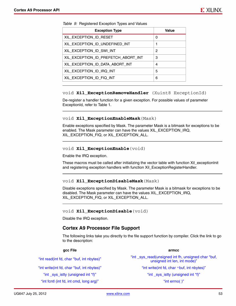
Cortex A9 Processor API
void Xil_ExceptionRemoveHandler (Xuint8 ExceptionId)
De-register a handler function for a given exception. For possible values of parameter ExceptionId, refer to Table 1.
void Xil_ExceptionEnableMask(Mask)
Enable exceptions specified by Mask. The parameter Mask is a bitmask for exceptions to be enabled. The Mask parameter can have the values XIL_EXCEPTION_IRQ, XIL_EXCEPTION_FIQ, or XIL_EXCEPTION_ALL.
void Xil_ExceptionEnable(void)
Enable the IRQ exception.
These macros must be called after initializing the vector table with function Xil_exceptionInit and registering exception handlers with function Xil_ExceptionRegisterHandler.
void Xil_ExceptionDisableMask(Mask)
Disable exceptions specified by Mask. The parameter Mask is a bitmask for exceptions to be disabled. The Mask parameter can have the values XIL_EXCEPTION_IRQ, XIL_EXCEPTION_FIQ, or XIL_EXCEPTION_ALL.
void Xil_ExceptionDisable(void)
Disable the IRQ exception.
Cortex A9 Processor File Support
The following links take you directly to the file support function by compiler. Click the link to go to the description:
Table 9: Registered Exception Types and Values
Exception Type Value
XIL_EXCEPTION_ID_RESET 0
XIL_EXCEPTION_ID_UNDEFINED_INT 1
XIL_EXCEPTION_ID_SWI_INT 2
XIL_EXCEPTION_ID_PREFETCH_ABORT_INT 3
XIL_EXCEPTION_ID_DATA_ABORT_INT 4
XIL_EXCEPTION_ID_IRQ_INT 5
XIL_EXCEPTION_ID_FIQ_INT 6
gcc File armcc
“int read(int fd, char *buf, int nbytes)” “int _sys_read(unsigned int fh, unsigned char *buf, unsigned int len, int mode)”
“int write(int fd, char *buf, int nbytes)” “int write(int fd, char *buf, int nbytes)”
“int _sys_istty (unsigned int *f)” “int _sys_istty (unsigned int *f)”
“int fcntl (int fd, int cmd, long arg)” “int errno( )”
UG647 July 25, 2012 www.xilinx.com 53

Cortex A9 Processor API
File support is limited to the stdin and stdout streams; consequently, the following functions are not necessary:
gcc• open( ) (in gcc/open.c)
• close( ) (in gcc/close.c)
• fstat( ) (in gcc/fstat.c)
• unlink( ) (in gcc/unlink.c)
• lseek( ) (in gcc/lseek.c)
armcc• _sys_open (in armcc/_sys_open.c)
• _sys_close (in armcc/_sys_close.c
These files are included for completeness and because they are referenced by the C library.
Cortex A9 gcc File Support Function Descriptions
int read(int fd, char *buf, int nbytes)
The read( ) function in gcc/read.c reads nbytes bytes from the standard input by calling inbyte( ). It blocks until all characters are available, or the end of line character is read. The read( ) function returns the number of characters read. The fd parameter is ignored.
int write(int fd, char *buf, int nbytes)
Writes nbytes bytes to the standard output by calling outbyte( ). It blocks until all characters have been written. The write( ) function returns the number of characters written. The fd parameter is ignored.
int isatty(int fd)
Reports if a file is connected to a tty. This function always returns 1, because only the stdin and stdout streams are supported.
int fcntl (int fd, int cmd, long arg)
A dummy implementation of fcntl, which always returns 0. fcntl is intended to manipulate file descriptors according to the command specified by cmd. Because Standalone does not provide a file system, this function is not used.
Cortex A9 armcc File Support Function Descriptions
int _sys_read(unsigned int fh, unsigned char *buf, unsigned int len, int mode)
The _sys_read( ) function in armcc/_sys_read.c reads nbytes bytes from the standard input by calling inbyte( ). It blocks until all characters are available, or the end of line character is read and returns the number of characters read. The fh and mode parameters are ignored.
54 www.xilinx.com UG647 July 25, 2012

Cortex A9 Processor API
int _sys_write(unsigned int fh, const unsigned char *buf, unsigned int len, int mode)
The _sys_write( ) function in armcc/_sys_write.c writes nbytes bytes to the standard output by calling outbyte( ). It blocks until all characters have been written and returns the number of characters written. The fh and mode parameters are ignored.
int _sys_istty (unsigned int *f)
The _sys_istty( ) function in armcc/_sys_istty.c reports if a file is connected to a tty. This function always returns 1, because only the stdin and stdout streams are supported.
Cortex A9 gcc Errno Function
int errno( )
Returns the global value of errno as set by the last C library call.
Cortex A9 gcc Memory Management
char *sbrk(int nbytes)
Allocates nbytes of heap and returns a pointer to that piece of memory. This function is called from the memory allocation functions of the C library.
Cortex A9 gcc Process Functions
The functions getpid( ) in getpid.c and kill( ) in kill.c are included for completeness and because they are referenced by the C library.
Cortex A9 Processor-Specific Include Files
The xreg_cortexa9.h include file contains the register numbers and the register bits for the ARM Cortex-A9 processor.
The xpseudo_asm.h include file contains the definitions for the most often used inline assembler instructions, available as macros. These can be very useful for tasks such as setting or getting special purpose registers, synchronization, or cache manipulation. These inline assembler instructions can be used from drivers and user applications written in C.
Cortex A9 Time Functions
The xtime_l.c file and corresponding xtime_l.h include file provide access to the 32-bit CPU Cycle Counter in the PMU. This counter increases by one at every 64 processor cycles. The sleep.c file and corresponding sleep.h include file implement sleep functions. Sleep functions are implemented as busy loops.
Cortex A9 Time Function Summary
The time functions are summarized below. Click on the function name to go to the description.
typedef unsigned long long XTime
void XTime_SetTime(XTime xtime)
void XTime_GetTime(XTime *xtime)
UG647 July 25, 2012 www.xilinx.com 55

Cortex A9 Processor API
unsigned int usleep(unsigned int useconds)
unsigned int sleep(unsigned int _seconds)
void nanosleep(unsigned int nanoseconds)
Cortex A9 Time Function Descriptions
typedef unsigned long long XTime
The XTime type in xtime_l.h is a 64-bit value, of which the lower 32-bits represent the CPU Cycle Counter and the higher 32-bits are used to keep track of the number of times the CPU Cycle counter overflows.
void XTime_SetTime(XTime xtime)
Sets the cycle counter and the overflow variable to the value in xtime.
void XTime_GetTime(XTime *xtime)
Writes the current value of the cycle counter and the overflow variable, to variable xtime.
unsigned int usleep(unsigned int useconds)
Delays the execution of a program by useconds microseconds. It returns zero if the delay can be achieved or -1 if the delay can't be achieved. This function requires that the processor frequency (in Hz) is defined in xparameters.h.
unsigned int sleep(unsigned int _seconds)
Delays the execution of a program by what is specified in seconds. It always returns zero. This function requires that the processor frequency (in Hz) is defined in xparameters.h.
void nanosleep(unsigned int nanoseconds)
The nanosleep( ) function in usleep.c is not implemented. It is a placeholder for linking applications against the C library.
Cortex A9 Event Counters
xpm_counter.c and xpm_counter.h provide APIs for configuring and controlling the Cortex-A9
Performance Monitor Events. Cortex-A9 Performance Monitor has 6 event counters which can be used to count a variety of events described in Coretx-A9 TRM.
xpm_counter.h defines configurations(XPM_CNTRCFGx) which specifies the event counters to count a set of events.
Cortex A9 Event Counters Function Summary
The Event Counters functions are summarized below. Click on the function name to go to the description.
void Xpm_SetEvents(int PmcrCfg)
void Xpm_GetEventCounters(u32 *PmCtrValue)
56 www.xilinx.com UG647 July 25, 2012

Xilinx Hardware Abstraction Layer
Cortex A9 Event Counters Function Description
void Xpm_SetEvents(int PmcrCfg)
This function configures the Cortex A9 event counters controller, with the event codes, in a configuration selected by the user and enables the counters.
PmcrCfg is configuration value based on which the event counters are configured.
Use XPM_CNTRCFG* values defined in xpm_counter.h to define a configuration which specify the event counters to count a set of events.
void Xpm_GetEventCounters(u32 *PmCtrValue)
This function disables the event counters and returns the counter values.
PmCtrValue returns the counter values.
Xilinx Hardware Abstraction Layer
The following sections describe the Xilinx® Hardware Abstraction Layer API. It contains the following sections:
• Types (xil_types)
• Register IO (xil_io)
• Exception (xil_exception)
• Cache (xil_cache)
• Assert (xil_assert)
• Extra Header File
• Test Memory (xil_testmem)
• Test Register IO (xil_testio)
• Test Cache (xil_testcache)
• Hardware Abstraction Layer Migration Tips
Types (xil_types)
Header File#include "xil_types.h"
Typedeftypedef unsigned char u8 typedef unsigned short u16typedef unsigned long u32typedef unsigned long long u64typedef char s8typedef short s16typedef long s32typedef long long s64
UG647 July 25, 2012 www.xilinx.com 57

Xilinx Hardware Abstraction Layer
Macros
Register IO (xil_io)
Header File#include "xil_io.h"
Common API
The following is a linked summary of register IO functions. They can run on MicroBlaze, PowerPC 405, and PowerPC 440 processors.
u8 Xil_In8(u32 Addr) u16 Xil_EndianSwap16 (u16 Data) u16 Xil_Htons(u16 Data) u16 Xil_In16(u32 Addr) u16 Xil_In16BE(u32 Addr) u16 Xil_In16LE(u32 Addr) u16 Xil_Ntohs(u16 Data) u32 Xil_EndianSwap32 u32 Data) u32 Xil_Htonl(u32 Data) u32 Xil_In32(u32 Addr) u32 Xil_In32BE(u32 Addr) u32 Xil_In32LE(u32 Addr) u32 Xil_Ntohs(u32 Data) void Xil_Out8(u32 Addr, u8 Value) void Xil_Out16(u32 Addr, u16 Value) void Xil_Out16BE(u32 Addr, u16 Value) void Xil_Out16LE(u32 Addr, u16 Value) void Xil_Out32(u32 Addr, u32 Value) void Xil_Out32BE(u32 Addr, u32 Value) void Xil_Out32LE(u32 Addr, u32 Value)
u8 Xil_In8(u32 Addr)
Perform an input operation for an 8-bit memory location by reading from the specified address and returning the value read from that address.
Parameters:
Addr contains the address at which to perform the input operation.
Returns:
The value read from the specified input address.
Macro Value
#define TRUE 1
#define FALSE 0
#define NULL 0
#define XIL_COMPONENT_IS_READY 0x11111111
#define XIL_COMPONENT_IS_STARTED 0x22222222
58 www.xilinx.com UG647 July 25, 2012

Xilinx Hardware Abstraction Layer
u16 Xil_EndianSwap16 (u16 Data)
Perform a 16-bit endian swapping.
Parameters:
Data contains the value to be swapped.
Returns:
Endian swapped value.
u16 Xil_Htons(u16 Data)
Convert a 16-bit number from host byte order to network byte order.
Parameters:
Data the 16-bit number to be converted.
Returns:
The converted 16-bit number in network byte order.
u16 Xil_In16(u32 Addr)
Perform an input operation for a 16-bit memory location by reading from the specified address and returning the value read from that address.
Parameters:
Addr contains the address at which to perform the input operation.
Returns:
The value read from the specified input address.
u16 Xil_In16BE(u32 Addr)
Perform an big-endian input operation for a 16-bit memory location by reading from the specified address and returning the value read from that address.
Parameters:
Addr contains the address at which to perform the input operation.
Returns:
The value read from the specified input address with the proper endianness. The return value has the same endianness as that of the processor. For example, if the processor is little-endian, the return value is the byte-swapped value read from the address.
UG647 July 25, 2012 www.xilinx.com 59

Xilinx Hardware Abstraction Layer
u16 Xil_In16LE(u32 Addr)
Perform a little-endian input operation for a 16-bit memory location by reading from the specified address and returning the value read from that address.
Parameters:
Addr contains the address at which to perform the input operation.
Returns:
The value read from the specified input address with the proper endianness. The return value has the same endianness as that of the processor. For example, if the processor is big-endian, the return value is the byte-swapped value read from the address.
u16 Xil_Ntohs(u16 Data)
Convert a 16-bit number from network byte order to host byte order.
Parameters:
Data the 16-bit number to be converted.
Returns:
The converted 16-bit number in host byte order.
u32 Xil_EndianSwap32 (u32 Data)
Perform a 32-bit endian swapping.
Parameters:
Data contains the value to be swapped.
Returns:
Endian swapped value.
u32 Xil_Htonl(u32 Data)
Convert a 32-bit number from host byte order to network byte order.
Parameters:
Data the 32-bit number to be converted.
Returns:
The converted 32-bit number in network byte order.
u32 Xil_In32(u32 Addr)
Perform an input operation for a 32-bit memory location by reading from the specified address and returning the value read from that address.
Parameters:
Addr contains the address at which to perform the input operation.
Returns:
The value read from the specified input address.
60 www.xilinx.com UG647 July 25, 2012

Xilinx Hardware Abstraction Layer
u32 Xil_In32BE(u32 Addr)
Perform a big-endian input operation for a 32-bit memory location by reading from the specified address and returning the value read from that address.
Parameters:
Addr contains the address at which to perform the input operation.
Returns:
The value read from the specified input address with the proper endianness. The return value has the same endianness as that of the processor. For example, if the processor is little-endian, the return value is the byte-swapped value read from the address.
u32 Xil_In32LE(u32 Addr)
Perform a little-endian input operation for a 32-bit memory location by reading from the specified address and returning the value read from that address.
Parameters:
Addr contains the address at which to perform the input operation.
Returns:
The value read from the specified input address with the proper endianness. The return value has the same endianness as that of the processor. For example, if the processor is big-endian, the return value is the byte-swapped value read from the address.
u32 Xil_Ntohs(u32 Data)
Convert a 32-bit number from network byte order to host byte order.
Parameters:
Data the 32-bit number to be converted.
Returns:
The converted 32-bit number in host byte order.
void Xil_Out8(u32 Addr, u8 Value)
Perform an output operation for an 8-bit memory location by writing the specified value to the specified address.
Parameters:
Addr contains the address at which to perform the output operation.
Value contains the value to be output at the specified address.
void Xil_Out16(u32 Addr, u16 Value)
Perform an output operation for a 16-bit memory location by writing the specified value to the specified address.
Parameters:
Addr contains the address at which to perform the output operation.
Value contains the value to be output at the specified address.
UG647 July 25, 2012 www.xilinx.com 61

Xilinx Hardware Abstraction Layer
void Xil_Out16BE(u32 Addr, u16 Value)
Perform a big-endian output operation for a 16-bit memory location by writing the specified value to the specified address.
Parameters:
Addr contains the address at which to perform the output operation.
Value contains the value to be output at the specified address. The value has the same endianness as that of the processor. For example, if the processor is little-endian, the byte-swapped value is written to the address.
void Xil_Out16LE(u32 Addr, u16 Value)
Perform a little-endian output operation for a 16-bit memory location by writing the specified value to the specified address.
Parameters:
Addr contains the address at which to perform the output operation.
Value contains the value to be output at the specified address. The value has the same endianness as that of the processor. For example, if the processor is big-endian, the byte-swapped value is written to the address.
void Xil_Out32(u32 Addr, u32 Value)
Perform an output operation for a 32-bit memory location by writing the specified value to the specified address.
Parameters:
Addr contains the address at which to perform the output operation.
Value contains the value to be output at the specified address.
void Xil_Out32BE(u32 Addr, u32 Value)
Perform a big-endian output operation for a 32-bit memory location by writing the specified value to the specified address.
Parameters:
Addr contains the address at which to perform the output operation.
Value contains the value to be output at the specified address. The value has the same endianness as that of the processor. For example, if the processor is little-endian, the byte-swapped value is written to the address.
void Xil_Out32LE(u32 Addr, u32 Value)
Perform a little-endian output operation for a 32-bit memory location by writing the specified value to the specified address.
Parameters:
Addr contains the address at which to perform the output operation.
Value contains the value to be output at the specified address. The value has the same endianness as that of the processor. For example, if the processor is big-endian, the byte-swapped value is written to the address.
62 www.xilinx.com UG647 July 25, 2012

Xilinx Hardware Abstraction Layer
Exception (xil_exception)
Header File#include "xil_exception.h"
Typedeftypedef void(* Xil_ExceptionHandler)(void *Data)
This typedef is the exception handler function pointer.
Common API
The following are exception functions. They can run on MicroBlaze, PowerPC 405, and PowerPC 440 processors.
void Xil_ExceptionDisable()
Disable Exceptions. On PowerPC 405 and PowerPC 440 processors, this function only disables non-critical exceptions.
void Xil_ExceptionEnable()
Enable Exceptions. On PowerPC 405 and PowerPC 440 processors, this function only enables non-critical exceptions.
void Xil_ExceptionInit()
Initialize exception handling for the processor. The exception vector table is set up with the stub handler for all exceptions.
void Xil_ExceptionRegisterHandler(u32 Id, Xil_ExceptionHandler Handler, void *Data)
Make the connection between the ID of the exception source and the associated handler that runs when the exception is recognized. Data is used as the argument when the handler is called.
Parameters:
Id contains the identifier (ID) of the exception source. This should be XIL_EXCEPTION_INT or be in the range of 0 to XIL_EXCEPTION_LAST. Refer to the xil_exception.h file for further information.
Handler is the handler for that exception.
Data is a reference to data that will be passed to the handler when it is called.
void Xil_ExceptionRemoveHandler(u32 Id)
Remove the handler for a specific exception ID. The stub handler is then registered for this exception ID.
Parameters:
Id contains the ID of the exception source. It should be XIL_EXCEPTION_INT or in the range of 0 to XIL_EXCEPTION_LAST. Refer to the xil_exception.h file for further information.
UG647 July 25, 2012 www.xilinx.com 63

Xilinx Hardware Abstraction Layer
Common Macro
The common macro is:
#define XIL_EXCEPTION_ID_INT
This macro is defined for all processors and used to set the exception handler that corresponds to the interrupt controller handler. The value is processor-dependent. For example:
Xil_ExceptionRegisterHandler(XIL_EXCEPTION_ID_INT, (XilExceptionHandler)IntcHandler, IntcData)
MicroBlaze Processor-Specific Macros
PowerPC 405 Processor-Specific Functions and Macros
The following functions and macros are used with PowerPC 405 Processors.
void Xil_ExceptionDisableMask(u32 Mask)
Disable exceptions.
Parameters:
Mask is a bitmask for exceptions to be disabled.
Macro Value
#define XIL_EXCEPTION_ID_FIRST 0
#define XIL_EXCEPTION_ID_FSL 0
#define XIL_EXCEPTION_ID_UNALIGNED_ACCESS 1
#define XIL_EXCEPTION_ID_ILLEGAL_OPCODE 2
#define XIL_EXCEPTION_ID_IOPB_EXCEPTION 3
#define XIL_EXCEPTION_ID_IPLB_EXCEPTION 3
#define XIL_EXCEPTION_ID_DOPB_EXCEPTION 4
#define XIL_EXCEPTION_ID_DPLB_EXCEPTION 4
#define XIL_EXCEPTION_ID_DIV_BY_ZERO 5
#define XIL_EXCEPTION_ID_FPU 6
#define XIL_EXCEPTION_ID_MMU 7
#define XIL_EXCEPTION_ID_LAST XIL_EXCEPTION_ID_MMU
64 www.xilinx.com UG647 July 25, 2012

Xilinx Hardware Abstraction Layer
void Xil_ExceptionEnableMask(u32 Mask)
Enable exceptions.
Parameters:
Mask is a bitmask for exceptions to be enabled.X-Ref Target - Figure 1
X-Ref Target - Figure 2
PowerPC 440 Processor-Specific Functions and Macros
The following functions and macros are used with PowerPC 440 Processors.
Table 10: Macros Used for Both Enabling and Disabling Exceptions
Macro Value
#define XIL_EXCEPTION_CRITICAL 0x00020000
#define XIL_EXCEPTION_NON_CRITICAL 0x00008000
#define XIL_EXCEPTION_ALL 0x00028000
Table 11: Macros Used for Registering Exceptions
Macro Value
#define XIL_EXCEPTION_ID_FIRST 0
#define XIL_EXCEPTION_ID_JUMP_TO_ZERO 0
#define XIL_EXCEPTION_ID_CRITICAL_INT 1
#define XIL_EXCEPTION_ID_MACHINE_CHECK 2
#define XIL_EXCEPTION_ID_DATA_STORAGE_INT 3
#define XIL_EXCEPTION_ID_INSTRUCTION_STORAGE_INT 4
#define XIL_EXCEPTION_ID_NON_CRITICAL_INT 5
#define XIL_EXCEPTION_ID_ALIGNMENT_INT 6
#define XIL_EXCEPTION_ID_PROGRAM_INT 7
#define XIL_EXCEPTION_ID_FPU_UNAVAILABLE_INT 8
#define XIL_EXCEPTION_ID_SYSTEM_CALL 9
#define XIL_EXCEPTION_ID_APU_AVAILABLE 10
#define XIL_EXCEPTION_ID_PIT_INT 11
#define XIL_EXCEPTION_ID_FIT_INT 12
#define XIL_EXCEPTION_ID_WATCHDOG_TIMER_INT 13
#define XIL_EXCEPTION_ID_DATA_TLB_MISS_INT 14
#define XIL_EXCEPTION_ID_INSTRUCTION_TLB_MISS_INT 15
#define XIL_EXCEPTION_ID_DEBUG_INT 16
#define XIL_EXCEPTION_ID_LAST 16
UG647 July 25, 2012 www.xilinx.com 65
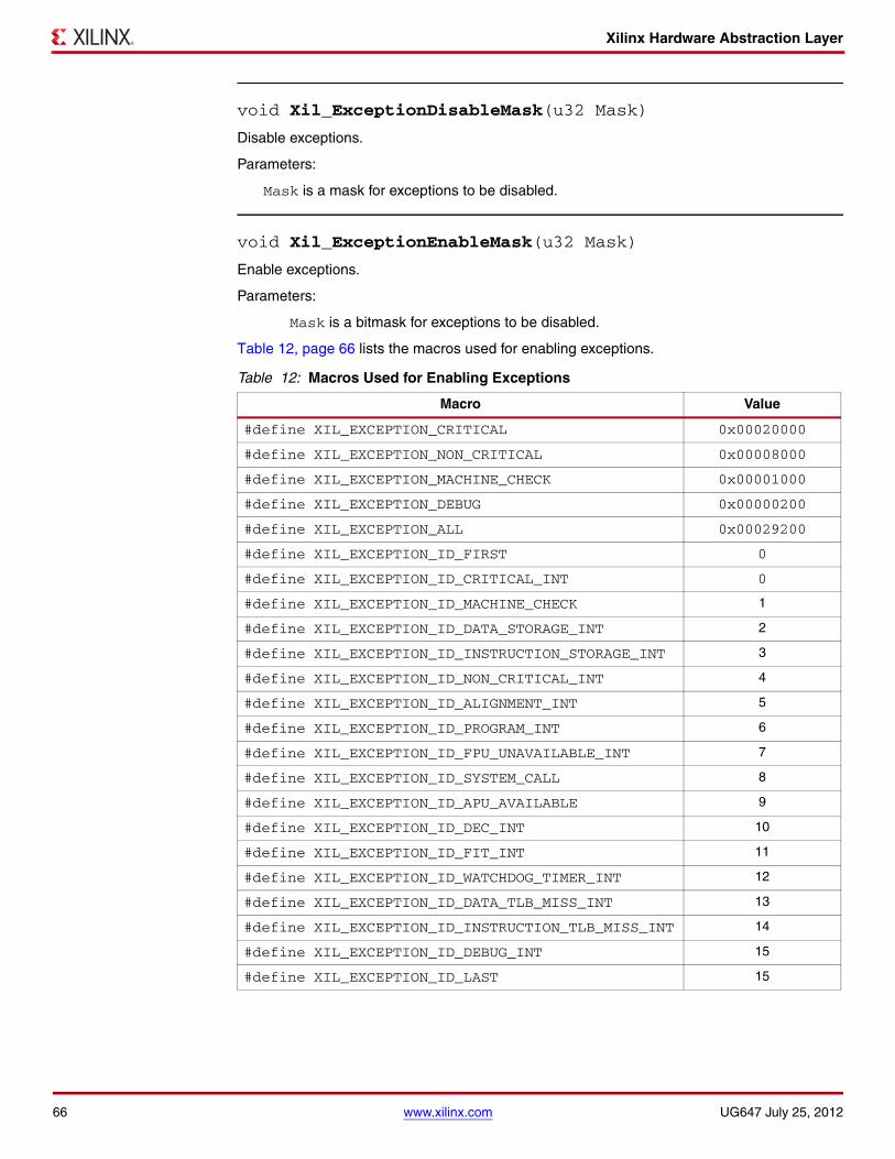
Xilinx Hardware Abstraction Layer
void Xil_ExceptionDisableMask(u32 Mask)
Disable exceptions.
Parameters:
Mask is a mask for exceptions to be disabled.
void Xil_ExceptionEnableMask(u32 Mask)
Enable exceptions.
Parameters:
Mask is a bitmask for exceptions to be disabled.
Table 12, page 66 lists the macros used for enabling exceptions.
Table 12: Macros Used for Enabling Exceptions
Macro Value
#define XIL_EXCEPTION_CRITICAL 0x00020000
#define XIL_EXCEPTION_NON_CRITICAL 0x00008000
#define XIL_EXCEPTION_MACHINE_CHECK 0x00001000
#define XIL_EXCEPTION_DEBUG 0x00000200
#define XIL_EXCEPTION_ALL 0x00029200
#define XIL_EXCEPTION_ID_FIRST 0
#define XIL_EXCEPTION_ID_CRITICAL_INT 0
#define XIL_EXCEPTION_ID_MACHINE_CHECK 1
#define XIL_EXCEPTION_ID_DATA_STORAGE_INT 2
#define XIL_EXCEPTION_ID_INSTRUCTION_STORAGE_INT 3
#define XIL_EXCEPTION_ID_NON_CRITICAL_INT 4
#define XIL_EXCEPTION_ID_ALIGNMENT_INT 5
#define XIL_EXCEPTION_ID_PROGRAM_INT 6
#define XIL_EXCEPTION_ID_FPU_UNAVAILABLE_INT 7
#define XIL_EXCEPTION_ID_SYSTEM_CALL 8
#define XIL_EXCEPTION_ID_APU_AVAILABLE 9
#define XIL_EXCEPTION_ID_DEC_INT 10
#define XIL_EXCEPTION_ID_FIT_INT 11
#define XIL_EXCEPTION_ID_WATCHDOG_TIMER_INT 12
#define XIL_EXCEPTION_ID_DATA_TLB_MISS_INT 13
#define XIL_EXCEPTION_ID_INSTRUCTION_TLB_MISS_INT 14
#define XIL_EXCEPTION_ID_DEBUG_INT 15
#define XIL_EXCEPTION_ID_LAST 15
66 www.xilinx.com UG647 July 25, 2012

Xilinx Hardware Abstraction Layer
Cache (xil_cache)
Header File#include "xil_cache.h"
Common API
The functions listed in this sub-section can be executed on all processors.
void Xil_DCacheDisable()
Disable the data cache.
void Xil_DCacheEnable()
On MicroBlaze processors, enable the data cache.
On PowerPC 405 processors, enable the data cache with region mask 0x80000001.
On PowerPC 440 processors, enable the data cache with region mask 0xC0000001.
void Xil_DCacheFlush()
Flush the entire data cache. If any cacheline is dirty (has been modified), it is written to system memory. The entire data cache will be invalidated.
void Xil_DCacheFlushRange(u32 Addr, u32 Len)
Flush the data cache for the given address range. If any memory in the address range (identified as Addr) has been modified (and are dirty), the modified cache memory will be written back to system memory. The cacheline will also be invalidated.
Parameters:
Addr is the starting address of the range to be flushed.
Len is the length, in bytes, to be flushed.
void Xil_DCacheInvalidate()
Invalidate the entire data cache. If any cacheline is dirty (has been modified), the modified contents are lost.
void Xil_DCacheInvalidateRange(u32 Addr, u32 Len)
Invalidate the data cache for the given address range. If the bytes specified by the address (Addr) are cached by the data cache, the cacheline containing that byte is invalidated. If the cacheline is modified (dirty), the modified contents are lost.
Parameters:
Addr is address of range to be invalidated.
Len is the length in bytes to be invalidated.
void Xil_ICacheDisable()
Disable the instruction cache.
UG647 July 25, 2012 www.xilinx.com 67

Xilinx Hardware Abstraction Layer
void Xil_ICacheEnable()
On MicroBlaze processors, enable the instruction cache.On PowerPC 405 processors, enable the instruction cache with region mask 0x80000001.On PowerPC 440 processors, enable the instruction cache with region mask 0xC0000001.
void Xil_ICacheInvalidate()
Invalidate the entire instruction cache.
void Xil_ICacheInvalidateRange(u32 Addr, u32 Len)
Invalidate the instruction cache for the given address range.
Parameters:
Addr is address of range to be invalidated.
Len is the length in bytes to be invalidated.
PowerPC 405 Processor-Specific Functions and Macros
The following functions are specific to PowerPC 405 processors.
void Xil_DCacheEnableRegion(u32 Regions)
void Xil_ICacheEnableRegion(u32 Regions)
void Xil_DCacheEnableRegion(u32 Regions)
Enable the data cache region.
Parameters:
void Xil_ICacheEnableRegion(u32 Regions)
Enable the instruction cache.
Parameters :
Regions1
1. Regions to be marked as cacheable. Each bit in the regions variable stands for 128 MB of memory.
Cached Address Range
0x80000000 [0, 0x7FFFFFF]
0x00000001 [0xF8000000, 0xFFFFFFFF]
0x80000001 [0, 0x7FFFFFF],[0xF8000000, 0xFFFFFFFF]
Regions1
1. Regions to be marked as cacheable. Each bit in the regions variable stands for 128 MB of memory.
Cached Address Range
0x80000000 [0, 0x7FFFFFF]
0x00000001 [0xF8000000, 0xFFFFFFFF]
0x80000001 [0, 0x7FFFFFF],[0xF8000000, 0xFFFFFFFF]
68 www.xilinx.com UG647 July 25, 2012

Xilinx Hardware Abstraction Layer
PowerPC 440 Processor-Specific Functions and Macros
The following functions are specific to PowerPC 440 processors.
void Xil_DCacheEnableRegion(u32 Regions)
Enable the data cache.
Parameters:
Regions1
1. Regions of memory to be marked as cacheable. Each pair of adjacent bits in the regions variable stands for 256 MB of memory. Setting either bit in the pair will enable caching for the corresponding region.
Cached Address Range
0x4000_0000
[0, 0x0FFF_FFFF] 0x8000_0000
0xC000_0000
0x0000_0001
[0xF000_0000, 0xFFFF_FFFF] 0x0000_0002
0x0000_0003
0x4000_0001
[0, 0x0FFF_FFFF],[0xF000_0000, 0xFFFF_FFFF]
0x4000_0002
0x4000_0003
0x8000_0001
0x8000_0002
0x8000_0003
0xC000_0001
0xC000_0002
0xC000_0003
UG647 July 25, 2012 www.xilinx.com 69

Xilinx Hardware Abstraction Layer
void Xil_ICacheEnableRegion(u32 Regions)
Enable the instruction cache.
Parameters:
Assert (xil_assert)
Header File
#include "xil_assert.h"
Typedeftypedef void(* Xil_AssertCallback)(char *Filename, int Line)
Common API
The functions listed in this sub-section can be executed on all processors.
void Xil_Assert(char *File, int Line)
Implement assert. Currently, it calls a user-defined callback function if one has been set. Then, potentially enters an infinite loop depending on the value of the Xil_AssertWait variable.
Parameters:
File is the name of the filename of the source.
Line is the line number within File.
Regions1
1. Regions of memory to be marked as cacheable. Each pair of adjacent bits in the regions variable stands for 256 MB of memory. Setting either bit in the pair will enable caching for the corresponding region.
Cached Address Range
0x4000_0000
[0, 0x0FFF_FFFF] 0x8000_0000
0xC000_0000
0x0000_0001
[0xF000_0000, 0xFFFF_FFFF] 0x0000_0002
0x0000_0003
0x4000_0001
[0, 0x0FFF_FFFF],[0xF000_0000, 0xFFFF_FFFF]
0x4000_0002
0x4000_0003
0x8000_0001
0x8000_0002
0x8000_0003
0xC000_0001
0xC000_0002
0xC000_0003
70 www.xilinx.com UG647 July 25, 2012

Xilinx Hardware Abstraction Layer
void Xil_AssertSetCallback(xil_AssertCallback Routine)
Set up a callback function to be invoked when an assert occurs. If there was already a callback installed, then it is replaced.
Parameters:
Routine is the callback to be invoked when an assert is taken.
#define Xil_AssertVoid(Expression)
This assert macro is to be used for functions that do not return anything (void). This can be used in conjunction with the Xil_AssertWait boolean to accommodate tests so that asserts that fail still allow execution to continue.
Parameters:
Expression is the expression to evaluate. If it evaluates to false, the assert occurs.
#define Xil_AssertNonvoid(Expression)
This assert macro is to be used for functions that return a value. This can be used in conjunction with the Xil_AssertWait boolean to accommodate tests so that asserts that fail still allow execution to continue.
Parameters:
Expression is the expression to evaluate. If it evaluates to false, the assert occurs.
Returns:
Returns 0 unless the Xil_AssertWait variable is true, in which case no return is made and an infinite loop is entered.
#define Xil_AssertVoidAlways()
Always assert. This assert macro is to be used for functions that do not return anything (void). Use for instances where an assert should always occur.
Returns:
Returns void unless the Xil_AssertWait variable is true, in which case no return is made and an infinite loop is entered.
#define Xil_AssertNonvoidAlways()
Always assert. This assert macro is to be used for functions that return a value. Use for instances where an assert should always occur.
Returns:
Returns void unless the xil_AssertWait variable is true, in which case no return is made and an infinite loop is entered.
UG647 July 25, 2012 www.xilinx.com 71

Xilinx Hardware Abstraction Layer
Extra Header File
The xil_hal.h header file is provided as a convenience. It includes all the header files related to the Hardware Abstraction Layer. The contents of this header file are as follows:
#ifndef XIL_HAL_H#define XIL_HAL_H
#include "xil_assert.h"#include "xil_exception.h"#include "xil_cache.h"#include "xil_io.h"#include "xil_types.h"
#endif
Test Memory (xil_testmem)
Description
A subset of the memory tests can be selected or all of the tests can be run in order. If there is an error detected by a subtest, the test stops and the failure code is returned. Further tests are not run even if all of the tests are selected.
Subtest Descriptions
XIL_TESTMEM_ALLMEMTESTS
Runs all of the subtests.
XIL_TESTMEM_INCREMENT
Incrementing Value test.
This test starts at XIL_TESTMEM_MEMTEST_INIT_VALUE and uses the incrementing value as the test value for memory.
XIL_TESTMEM_WALKONES
Walking Ones test.
This test uses a walking “1“ as the test value for memory.
location 1 = 0x00000001location 2 = 0x00000002...
XIL_TESTMEM_WALKZEROS
Walking Zeros test.
This test uses the inverse value of the walking ones test as the test value for memory.
location 1 = 0xFFFFFFFElocation 2 = 0xFFFFFFFD...
72 www.xilinx.com UG647 July 25, 2012

Xilinx Hardware Abstraction Layer
XIL_TESTMEM_INVERSEADDR
Inverse Address test.
This test uses the inverse of the address of the location under test as the test value for memory.
XIL_TESTMEM_FIXEDPATTERN
Fixed Pattern test.
This test uses the provided patterns as the test value for memory.
If zero is provided as the pattern, the test uses 0xDEADBEEF.
Caution! The tests are DESTRUCTIVE. Run them before any initialized memory spaces have been set up. The address provided to the memory tests is not checked for validity, except for the case where the value is NULL. It is possible to provide a code-space pointer for this test to start with and ultimately destroy executable code causing random failures.
Note: This test is used for spaces where the address range of the region is smaller than the data width. If the memory range is greater than 2 to the power of width, the patterns used in XIL_TESTMEM_WALKONES and XIL_TESTMEM_WALKZEROS will repeat on a boundary of a power of two, making it more difficult to detect addressing errors. The XIL_TESTMEM_INCREMENT and XIL_TESTMEM_INVERSEADDR tests suffer the same problem. If you need to test large blocks of memory, it is recommended that you break them up into smaller regions of memory to allow the test patterns used not to repeat over the region tested.
Header File#include "xil_testmem.h"
Common API
int Xil_Testmem8(u8 *Addr, u32 Words, u8 Pattern, u8 Subtest)
Perform a destructive 8-bit wide memory test.
Parameters:
Addr is a pointer to the region of memory to be tested.
Words is the length of the block.
Pattern is the constant used for the constant pattern test, if 0, 0xDEADBEEF is used.
Subtest is the test selected. See xil_testmem.h for possible values.
Returns:
-1 is returned for a failure
0 is returned for a pass
Note: Used for spaces where the address range of the region is smaller than the data width. If the memory range is greater than 2 to the power of width, the patterns used in XIL_TESTMEM_WALKONES and XIL_TESTMEM_WALKZEROS repeat on a boundary of a power of two, which makes detecting addressing errors more difficult. This is true of XIL_TESTMEM_INCREMENT and XIL_TESTMEM_INVERSEADDR tests also. If you need to test large blocks of memory, it is recommended that you break them up into smaller regions of memory to allow the test patterns used not to repeat over the region tested.
UG647 July 25, 2012 www.xilinx.com 73

Xilinx Hardware Abstraction Layer
int Xil_Testmem16(u16 *Addr, u32 Words, u16 Pattern, u8 Subtest)
Perform a destructive 16-bit wide memory test.
Parameters:
Addr is a pointer to the region of memory to be tested.
Words is the length of the block.
Pattern is the constant used for the constant pattern test, if 0, 0xDEADBEEF is used.
Subtest is the test selected. See xil_testmem.h for possible values.
Returns:
-1 is returned for a failure.
0 is returned for a pass.
Note: Used for spaces where the address range of the region is smaller than the data width. If the memory range is greater than 2 to the power of width, the patterns used in XIL_TESTMEM_WALKONES and XIL_TESTMEM_WALKZEROS repeat on a boundary of a power of two, making detecting addressing errors more difficult.
This is true of XIL_TESTMEM_INCREMENT and XIL_TESTMEM_INVERSEADDR tests also. If you need to test large blocks of memory, it is recommended that you break them up into smaller regions of memory to allow the test patterns used not to repeat over the region tested.
int Xil_Testmem32 (u32 *Addr, u32 Words, u32 pattern, u8 Subtest)
Perform a destructive 32-bit wide memory test.
Parameters:
Addr is a pointer to the region of memory to be tested.
Words is the length of the block.
Pattern is the constant used for the constant pattern test, if 0, 0xDEADBEEF is used.
Subtest is the test selected. See xil_testmem.h for possible values.
Returns:
0 is returned for a pass.
-1 is returned for a failure.
Note: This test is used for spaces where the address range of the region is smaller than the data width. If the memory range is greater than 2 to the power of width, the patterns used in XIL_TESTMEM_WALKONES and XIL_TESTMEM_WALKZEROS repeat on a boundary of a power of two, making detecting addressing errors more difficult. This is true of the XIL_TESTMEM_INCREMENT and XIL_TESTMEM_INVERSEADDR tests also. If you need to test large blocks of memory, it is recommended that you break them up into smaller regions of memory to allow the test patterns used not to repeat over the region tested.
Test Register IO (xil_testio)
This file contains utility functions to teach endian-related memory I/O functions.
Header File#include "xil_testio.h"
74 www.xilinx.com UG647 July 25, 2012

Xilinx Hardware Abstraction Layer
Common API
int Xil_TestIO8(u8 *Addr, int Len, u8 Value)
Perform a destructive 8-bit wide register IO test where the register is accessed using Xil_Out8 and Xil_In8. the Xil_TestIO8 function compares the read and write values.
Parameters:
Addr is a pointer to the region of memory to be tested.
Len is the length of the block.
Value is the constant used for writing the memory.
Returns:
0 is returned for a pass.
-1 is returned for a failure.
int Xil_TestIO16(u8 *Addr, int Len, u16 Value, int Kind, int Swap)
Perform a destructive 16-bit wide register IO test. Each location is tested by sequentially writing a 16-bit wide register, reading the register, and comparing value. This function tests three kinds of register IO functions, normal register IO, little-endian register IO, and big-endian register IO. When testing little/big-endian IO, the function performs the following sequence:
Xil_Out16LE/Xil_Out16BE, Xil_In16, Compare In-Out values, Xil_Out16, Xil_In16LE/Xil_In16BE, Compare In-Out values. Whether to swap the read-in value before comparing is controlled by the 5th argument.
Parameters:
Addr is a pointer to the region of memory to be tested.
Len is the length of the block.
Value is the constant used for writing the memory.
Kind is the test kind. Acceptable values are: XIL_TESTIO_DEFAULT, XIL_TESTIO_LE, XIL_TESTIO_BE.
Swap indicates whether to byte swap the read-in value.
Returns:
0 is returned for a pass.
-1 is returned for a failure.
UG647 July 25, 2012 www.xilinx.com 75

Xilinx Hardware Abstraction Layer
int Xil_TestIO32(u8 *Addr, int Len, u32 Value, int Kind, int Swap)
Perform a destructive 32-bit wide register IO test. Each location is tested by sequentially writing a 32-bit wide register, reading the register, and comparing value. This function tests three kinds of register IO functions, normal register IO, little-endian register IO, and big-endian register IO. When testing little/big-endian IO, the function performs the following sequence: Xil_Out32LE/Xil_Out32BE, Xil_In32, Compare In-Out values, Xil_Out32, Xil_In32LE/Xil_In32BE, Compare In-Out values. Whether to swap the read-in value before comparing is controlled by the 5th argument.
Parameters:
Addr is a pointer to the region of memory to be tested.
Len is the length of the block.
Value is the constant used for writing the memory.
Kind is the test kind. Acceptable values are: XIL_TESTIO_DEFAULT, XIL_TESTIO_LE, XIL_TESTIO_BE.
Swap indicates whether to byte swap the read-in value.
Returns:
0 is returned for a pass.
-1 is returned for a failure.
Test Cache (xil_testcache)
This file contains utility functions to test the cache.
Header File#include "xil_testcache.h"
Common API
int Xil_TestDCacheAll()
Tests the DCache related functions on all related API tests such as Xil_DCacheFlush and Xil_DCacheInvalidate. This test function writes a constant value to the data array, flushes the DCache, writes a new value, and then invalidates the DCache.
Returns:
0 is returned for a pass.
-1 is returned for a failure.
int Xil_TestDCacheRange()
Tests the DCache range-related functions on a range of related API tests such as Xil_DCacheFlushRange and Xil_DCacheInvalidate_range. This test function writes a constant value to the data array, flushes the range, writes a new value, and then invalidates the corresponding range.
Returns:
0 is returned for a pass.
-1 is returned for a failure.
76 www.xilinx.com UG647 July 25, 2012

Xilinx Hardware Abstraction Layer
int Xil_TestICacheAll()
Perform xil_icache_invalidate().
Returns:
0 is returned for a pass. The function will hang if it fails.
int Xil_TestICacheRange()
Perform Xil_ICacheInvalidateRange() on a few function pointers.
Returns:
0 is returned for a pass. The function will hang if it fails.
Hardware Abstraction Layer Migration Tips
Mapping Header Files to HAL Header Files
You can map old header files to the new HAL header files as listed in Table 13.
Table 13: HAL Header File Mapping
Area Old Header File New Header File
Register IO “xio.h“ “xil_io.h”
Exception “xexception_l.h”“mb_interface.h” “xil_exception.h”
Cache “xcache.h”“mb_interface.h” “xil_cache.h”
Interrupt “xexception_l.h”“mb_interface.h” “xil_exception.h”
Typedef u8 u16 u32 “xbasic_types.h” “xil_types.h”
Typedef of Xuint32 Xfloat32 ... “xbasic_types.h” Deprecated. Do not use.
Assert “xbasic_types.h” “xil_assert.h”
Test Memory “xutil.h” “xil_testmem.h”
Test Register IO None “xil_testio.h”
Test Cache None “xil_testcache.h”
UG647 July 25, 2012 www.xilinx.com 77

Xilinx Hardware Abstraction Layer
Mapping Functions to HAL Functions
You can map old functions to the new HAL functions as follows.
Table 14: I/O Function Mapping
Old xio New xil_io
#include “xio.h” #include “xil_io.h”
XIo_ln8 Xil_In8
XIo_Out8 Xil_Out8
XIo_In16 Xil_In16
XIo_Out16 Xil_Out16
XIo_In32 Xil_In32
XIo_Out32 Xil_Out32
Table 15: Exception Function Mapping
Old xexception New Xil_exception
#include “xexception_l.h”#include “mb_interface.h” #include “xil_exception.h”
XExc_Init Xil_ExceptionInit
XExc_mEnableExceptionmicroblaze_enable_exceptions
For all processors: Xil_ExceptionEnable(void)For PowerPC Only: Xil_ExceptionEnableMask(void)
XExc_registerHandlermicroblaze_register_exception_handler Xil_ExceptionRegisterHandler
XExc_RemoveHandler Xil_ExceptionRemoveHandler
XExc_mDisableExceptionsmicroblaze_disable_exceptions Xil_ExceptionDisable
Table 16: Interrupt Function Mapping
Old Interrupt New Xil_interrupt
#include “xexception_l.h” #include “xil_exception.h”
XExc_RegisterHandler(XEXC_ID_NON_CRITICAL, handler)microblaze_register_handler(handler)
Xil_ExceptionRegisterHandler(XIL_EXCEPTION_ID_INT, handler)
78 www.xilinx.com UG647 July 25, 2012

Xilinx Hardware Abstraction Layer
Table 17: Cache Function Mapping
Old xcache New xil_cache
#include “Xcache_l.h”#include “mb_interface.h” #include “xil_cache.h”
XCache_EnableDCachemicroblaze_enable_dcache
For all processors: Xil_DCacheEnable(void)For PowerPC only: Xil_DCacheEnableRegion(regions)
XCache_DisableDCachemicroblaze_disable_dcache Xil_DCacheDisable
XCache_InvalidateDCacheRangemicroblaze_invalidate_dcache_range Xil_DCacheInvalidateRange
microblaze_invalidate_dcache Xil_DCacheInvalidate
XCache_FlushDCacheRangemicroblaze_flush_dcache_range Xil_DCacheFlushRange
microblaze_flush_dcache Xil_DCacheFlush
XCache_EnableICachemicroblaze_enable_icache
For all processors: Xil_ICacheEnable(void)For PowerPC only: Xil_ICacheEnableRegion(regions)
XCache_DisableICachemicroblaze_disable_icache Xil_ICacheDisable
XCache_InvalidateICacheRangemicroblaze_invalidate_icache_Range Xil_ICacheInvalidateRange
microblaze_invalidate_icache Xil_ICacheInvalidate
Table 18: Assert Function Mapping
Old ASSERT New xil_assert
#include “xbasic_types.h” #include “xil_assert.h”
XAssert Xil_Assert
XASSERT_VOID Xil_AssertVoid
XASSERT_NONVOID Xil_AssertNonvoid
XASSERT_VOID_ALWAYS Xil_AssertVoidAlways
XASSERT_NONVOID_ALWAYS Xil_AssertNonvoidAlways
XAssertSetCallback Xil_AssertSetCallback
Table 19: Memory Test Function Mapping
Old XUtil_Memtest New xil_util_testmem
#include “xutil.h” #include “xil_util_testmem.h”
XUtil_MemoryTest32 Xil_Testmem32
XUtil_MemoryTest16 Xil_Testmem16
XUtil_MemoryTest8 Xil_Testmem8
UG647 July 25, 2012 www.xilinx.com 79

Program Profiling
Program Profiling
The Standalone OS supports program profiling in conjunction with the GNU compiler tools and the Xilinx Microprocessor Debugger (XMD). Profiling a program running on a hardware (board) provides insight into program execution and identifies where execution time is spent. The interaction of the program with memory and other peripherals can be more accurately captured.
Program running on hardware target is profiled using software intrusive method. In this method, the profiling software code is instrumented in the user program. The profiling software code is a part of the libxil.a library and is generated when software intrusive profiling is enabled in Standalone. For more details on about profiling, refer to the “Profile Overview” section of the SDK Help.
When the -pg profile option is specified to the compiler (either mb-gcc or powerpc-eabi-gcc), the profiling functions are linked with the application to profile automatically. The generated executable file contains code to generate profile information.
Upon program execution, this instrumented profiling function stores information on the hardware. XMD collects the profile information and generates the output file, which can be read by the GNU gprof tool. The program functionality remains unchanged but it slows down the execution.
Note: The profiling functions do not have any explicit application API. The library is linked due to profile calls (_mcount) introduced by GCC for profiling.
Profiling Requirements• Software intrusive profiling requires memory for storing profile information. You can use
any memory in the system for profiling.
• A timer is required for sampling instruction address. The xps_timer is the supported profile timer. For PowerPC processor systems, the Programmable Interrupt Timer (PIT) can be used as profile timer also.
Profiling Functions
_profile_init
Called before the application main( ) function. Initializes the profile timer routine and registers timer handler accordingly, based on the timer used, connects to the processor, and starts the timer. The Tcl routine of Standalone library determines the timer type and the connection to processor, then generates the #defines in the profile_config.h file.
Refer to the “Microprocessor Library Definition (MLD)” chapter in the Embedded System Tools Reference Manual (UG111), which is available in the installation directory. A link to this document is also provided in “MicroBlaze Processor API,” page 1.
_mcount
Called by the _mcount function, which is inserted at every function start by gcc. Records the caller and callee information (Instruction address), which is used to generate call graph information.
_profile_intr_handler
The interrupt handler for the profiling timer. The timer is set to sample the executing application for PC values at fixed intervals and increment the Bin count. This function is used to generate the histogram information.
80 www.xilinx.com UG647 July 25, 2012

Configuring the Standalone OS
Configuring the Standalone OS
You can configure the Standalone OS using the Board Support Package Settings dialog box in SDK.
Table 20 lists the configurable parameters for the Standalone OS.
MicroBlaze MMU Example
The tlb_add function adds a single TLB entry. The parameters are:
static inline void tlb_add(int tlbindex, unsigned int tlbhi, unsigned int tlblo){ __asm__ __volatile__ ("mts rtlbx, %2 \n\t" "mts rtlbhi, %0 \n\t" "mts rtlblo, %1 \n\t" :: "r" (tlbhi), "r" (tlblo), "r" (tlbindex));
tlbentry[tlbindex].tlbhi = tlbhi; tlbentry[tlbindex].tlblo = tlblo; }
Given a base and high address, the tlb_add_entries function figures the minimum number page mappings/TLB entries required to cover the area. This function uses recursion to figure the entire range of mappings.
Table 20: Configuration Parameters
Parameter Type Default Value Description
enable_sw_intrusive_profiling
Bool false Enable software intrusive profiling functionality. Select true to enable.
profile_timer Peripheral Instance
none Specify the timer to use for profiling.
Select an xps_timer or axi_timer from the list of displayed instances.
For a PowerPC system, select none to use the built-in PIT timer.
stdin Peripheral Instance
none Specify the STDIN peripheral from the drop down list
stdout Peripheral Instance
none Specify the STDOUT peripheral from the drop down list.
predecode_fpu_exception Bool false This parameter is valid only for MicroBlaze processor when FPU exceptions are enabled in the hardware. Setting this to true will include extra code that decodes and stores the faulting FP instruction operands in global variables.
tlbindex The index of the TLB entry to be updated.
tlbhi The value of the TLBHI field.
tlblo The value of the TLBLO field.
UG647 July 25, 2012 www.xilinx.com 81

MicroBlaze MMU Example
Parameters:
Returns: 1 on success and 0 on failure
static int tlb_add_entries (unsigned int base, unsigned int high, unsigned int tlbaccess) { int sizeindex, tlbsizemask; unsigned int tlbhi, tlblo; unsigned int area_base, area_high, area_size; static int tlbindex = 0;
// Align base and high to 1KB boundaries base = base & 0xfffffc00; high = (high >= 0xfffffc00) ? 0xffffffff : ((high + 0x400) & 0xfffffc00) - 1; // Start trying to allocate pages from 16 MB granularity down to 1 KB area_size = 0x1000000; // 16 MB tlbsizemask = 0x380; // TLBHI[SIZE] = 7 (16 MB)
for (sizeindex = 7; sizeindex >= 0; sizeindex--) { area_base = base & sizemask[sizeindex]; area_high = area_base + (area_size - 1);
// if (area_base <= (0xffffffff - (area_size - 1))) {
if ((area_base >= base) && (area_high <= high)) { if (tlbindex < TLBSIZE) { tlbhi = (base & sizemask[sizeindex]) | tlbsizemask | 0x40; // TLBHI: TAG, SIZE, V tlblo = (base & sizemask[sizeindex]) | tlbaccess | 0x8; // TLBLO: RPN, EX, WR, W tlb_add (tlbindex, tlbhi, tlblo);
tlbindex++; } else { // We only handle the 64 entry UTLB management for now return 0; } // Recursively add entries for lower area if (area_base > base) if (!tlb_add_entries (base, area_base - 1, tlbaccess)) return 0;
base The base address of the region of memory
high The high address of the region of memory
tlbaccess The type of access required for this region of memory. It can be a logical or -ing of the following flags:
0 indicates read-only accessTLB_ACCESS_EXECUTABLE means the region is executableTLB_ACCESS_WRITABLE means the region is writable
82 www.xilinx.com UG647 July 25, 2012

MicroBlaze MMU Example
// Recursively add entries for higher area if (area_high < high) if (!tlb_add_entries(area_high + 1, high, tlbaccess)) return 0; break; } // else, we try the next lower page size area_size = area_size >> 2; tlbsizemask = tlbsizemask - 0x80; } return 1;}
For a complete example, refer to: $XILINX_EDK/sw/lib/bsp/xilkernel_v5_00_a/src/src/arch/microblaze/mpu.c.
UG647 July 25, 2012 www.xilinx.com 83


Overview Xilkernel is a small, robust, and modular kernel. It is highly integrated with the Platform Studio framework and is a free software library that you receive with the Xilinx Embedded Development Kit (EDK). Xilkernel:
• Allows a high degree of customization, letting you tailor the kernel to an optimal level both in terms of size and functionality.
• Supports the core features required in a lightweight embedded kernel, with a POSIX API.
• Works on MicroBlaze™, PowerPC® 405, and PowerPC 440 processors.
Xilkernel IPC services can be used to implement higher level services (such as networking, video, and audio) and subsequently run applications using these services.
Why Use a Kernel?
The following are a few of the deciding factors that can influence your choice of using a kernel as the software platform for your next application project:
• Typical embedded control applications comprise various tasks that need to be performed in a particular sequence or schedule. As the number of control tasks involved grows, it becomes difficult to organize the sub-tasks manually, and to time-share the required work. The responsiveness and the capability of such an application decreases dramatically when the complexity is increased.
• Breaking down tasks as individual applications and implementing them on an operating system (OS) is much more intuitive.
• A kernel enables the you to write code at an abstract level, instead of at a small, micro-controller-level standalone code.
• Many common and legacy applications rely on OS services such as file systems, time management, and so forth. Xilkernel is a thin library that provides these essential services. Porting or using common and open source libraries (such as graphics or network protocols) might require some form of these OS services also.
Key Features Xilkernel includes the following key features:
• High scalability into a given system through the inclusion or exclusion of functionality as required.
• Complete kernel configuration and deployment within minutes from inside of SDK.
• Robustness of the kernel: system calls protected by parameter validity checks and proper return of POSIX error codes.
• A POSIX API targeting embedded kernels, win core kernel features such as:
- Threads with round-robin or strict priority scheduling.
- Synchronization services: semaphores and mutex locks.
- IPC services: message queues and shared memory.
- Dynamic buffer pool memory allocation.
- Software timers.
- User-level interrupt handling.
• Static thread creation that startup with the kernel.
UG646 October 19, 2011
Xilkernel (v5.01.a)
UG646 October 19, 2011 www.xilinx.com 1
© 2011 Xilinx, Inc. XILINX, the Xilinx logo, Virtex, Spartan, ISE, and other designated brands included herein are trademarks of Xilinx in the United

Additional Resources
• System call interface to the kernel.
• Exception handling for the MicroBlaze processor.
• Memory protection using MicroBlaze Memory Management (Protection) Unit (MMU) features when available.
Additional Resources
• Xilkernel-based example designs:http://www.xilinx.com/ise/embedded/edk_examples.htm
Xilkernel Organization
The kernel is highly modular in design. You can select and customize the kernel modules that are needed for the application at hand. Customizing the kernel is discussed in detail in “Kernel Customization,” page 43(1). Figure 1 shows the various modules of Xilkernel:
Building Xilkernel Applications
Xilkernel is organized in the form of a library of kernel functions. This leads to a simple model of kernel linkage. To build Xilkernel, you must include Xilkernel in your software platform, configure it appropriately, and run Libgen to generate the Xilkernel library. Your application sources can be edited and developed separately. After you have developed your application, you must link with the Xilkernel library, thus pulling in all the kernel functionality to build the final kernel image. The Xilkernel library is generated as libxilkernel.a. Figure 2, page 3 shows this development flow.
Internally, Xilkernel also supports the much more powerful, traditional OS-like method of linkage and separate executables. Conventional operating systems have the kernel image as a separate file and each application that executes on the kernel as a separate file. However, Xilinx recommends that you use the more simple and more elegant library linkage mode. This mode provides maximum ease of use. It is also the preferred mode for debugging, downloading, and bootloading. The separate executable mode is required only by those who have advanced requirements in the form of separate executables. The separate executable mode and its caveats are documented in “Deprecated Features,” page 51.
The following are the steps for the kernel linkage mode of application development:
X-Ref Target - Figure 1
Figure 1: Xilkernel Modules
1. Some of these features might not be fully supported in a given release of Xilkernel.
System Call HandlerInterrupt and Exception
HandlerScheduler
SoftwareTimers
MessageQueue
ThreadManagement
SharedMemory
Semaphores
User level interrupthandling
User Application
Dynamic BufferManagement
Xilkernel
Xilkernel Modules
X10226
2 www.xilinx.com UG646 October 19, 2011

Building Xilkernel Applications
1. Application source C files should include the file xmk.h as the first file among others. For example, defining the includexmk.h flag makes available certain definitions and declarations from the GNU include files that are required by Xilkernel and applications.
2. Your application software project links with the library libxil.a. This library contains the actual kernel functions generated. Your application links with this and forms the final kernel and application image.
3. Xilkernel is responsible for all first level interrupt and exception handling on both the MicroBlaze and PowerPC processors. Therefore, you should not directly attempt to use any of the methods of handling interrupts documented for standalone programs. Instead refer to the section on interrupt handling for how to handle user level interrupts and exceptions.
4. You can control the memory map of the kernel by using the linker script feature of the final software application project that links with the kernel. Automatic linker script generation helps you here.
5. Your application must provide a main( ) which is the starting point of execution for your kernel image. Inside your main( ), you can do any initialization and setup that you need to do. The kernel remains unstarted and dormant. At the point where your application setup is complete and you want the kernel to start, you must invoke xilkernel_main( ) that starts off the kernel, enables interrupts, and transfers control to your application processes, as configured. Some system-level features may need to be enabled before invoking xilkernel_main( ). These are typically machine-state features such as cache enablement, hardware exception enablement which must be “always ON” even when context switching from application to application. Make sure that you setup such system state before invoking xilkernel_main( ). Also, you must not arbitrarily modify such system-state in your application threads. If a context switch occurs when the system state is modified, it could lead to subsequent threads executing without that state being enabled; consequently, you must lock out context switches and interrupts before you modify such a state.
Note: Your linker script must be aware of the requirements for the kernel. For example, on PowerPC 405 systems, there is a.vectors section that contains all first level exception handling code. Your final linker script must make sure that this section receives proper memory assignment.
X-Ref Target - Figure 2
Figure 2: Xilkernel Development Flow
Proc3Proc2Proc1
User Space
System Call Handler
Pure Separate Executable Mode Scenario
xilkernel.elf
Kernel Image
Proc6Proc5Proc4
User Space
System Call Handler
Kernel Bundled Executable Mode Scenario
libxilkernel.a
Sys
tem
Cal
lW
rapp
ers
Kernel Image
X10128
Proc1
Proc2
Proc3
UG646 October 19, 2011 www.xilinx.com 3

Xilkernel Process Model
Xilkernel Process Model
The units of execution within Xilkernel are called process contexts. Scheduling is done at the process context level. There is no concept of thread groups combining to form, what is conventionally called a process. Instead, all the threads are peers and compete equally for resources. The POSIX threads API is the primary user-visible interface to these process contexts. There are a few other useful additional interfaces provided, that are not a part of POSIX. The interfaces allow creating, destroying, and manipulating created application threads. The actual interfaces are described in detail in “Xilkernel API,” page 6. Threads are manipulated with thread identifiers. The underlying process context is identified with a process identifier pid_t.
Xilkernel Scheduling Model
Xilkernel supports either priority-driven, preemptive scheduling with time slicing (SCHED_PRIO) or simple round-robin scheduling (SCHED_RR). This is a global scheduling policy and cannot be changed on a per-thread basis. This must be configured statically at kernel generation time.
In SCHED_RR, there is a single ready queue and each process context executes for a configured time slice before yielding execution to the next process context in the queue.
In SCHED_PRIO there are as many ready queues as there are priority levels. Priority 0 is the highest priority in the system and higher values mean lower priority.
As shown in the following figure, the process that is at the head of the highest priority ready queue is always scheduled to execute next. Within the same priority level, scheduling is round-robin and time-sliced. If a ready queue level is empty, it is skipped and the next ready queue level examined for schedulable processes. Blocked processes are off their ready queues and in their appropriate wait queues. The number of priority levels can be configured for SCHED_PRIO.
For both the scheduling models, the length of the ready queue can also be configured. If there are wait queues inside the kernel (in semaphores, message queues), they are configured as priority queues if scheduling mode is SCHED_PRIO. Otherwise, they are configured as simple first-in-first-out (FIFO) queues.X-Ref Target - Figure 3
Figure 3: Priority-Driven Scheduling
A0
1
2
13
14
15
B
Active
C D(Blocked)
E
Prio
rity
F
G(Blocked)
X10132
4 www.xilinx.com UG646 October 19, 2011

Xilkernel Scheduling Model
Each process context is in any of the following six states:
• PROC_NEW - A newly created process.
• PROC_READY - A process ready to execute.
• PROC_RUN - A process that is running.
• PROC_WAIT - A process that is blocked on a resource.
• PROC_DELAY - A process that is waiting for a timeout.
• PROC_TIMED_WAIT - A process that is blocked on a resource and has an associated timeout.
When a process terminates, it enters a dead state called PROC_DEAD. The process context state diagram is shown in the following figure.X-Ref Target - Figure 4
Figure 4: Process Context States
kille
d killed
kille
d
killed
EX
IT
AC
TIV
AT
ED
SCHEDULED OUT
SCHEDULED IN
TIMEOUT
BLOCKED
BLO
CK
ED
UN
BLO
CK
ED
BLO
CK
ED
UN
BLO
CK
ED
/TIM
EO
UT
PROC_READY PROC_WAITPROC_TIMED
_WAITPROC_DELAY
PROC_RUN
PROC_DEAD
PROC_NEW
X10227
UG646 October 19, 2011 www.xilinx.com 5

POSIX Interface
POSIX Interface Xilkernel provides a POSIX interface to the kernel. Not all the concepts and interfaces defined by POSIX are available. A subset covering the most useful interfaces and concepts are implemented. Xilkernel programs can run almost equivalently on your desktop OS, like Linux or SunOS. This makes for easy application development, portability and legacy software support. The programming model appeals to those who have worked on equivalent POSIX interfaces on traditional operating systems. For those interfaces that have been provided, POSIX is rigorously adhered to in almost all cases. For cases that do differ, the differences are clearly specified. Refer to “Xilkernel API”, for the actual interfaces and their descriptions.
Xilkernel Functions
Click an item below view function summaries and descriptions for:
• Thread Management
• Semaphores
• Message Queues
• Shared Memory
• Mutex Locks
• Dynamic Buffer Memory Management
• Software Timers
• Memory Protection Overview
Xilkernel API Thread Management
Xilkernel supports the basic POSIX threads API. Thread creation and manipulation is done in standard POSIX notation. Threads are identified by a unique thread identifier. The thread identifier is of type pthread_t. This thread identifier uniquely identifies a thread for an operation. Threads created in the system have a kernel wrapper to which they return control to when they terminate. So, a specific exit function is not required at the end of the thread’s code.
Thread stack is allocated automatically on behalf of the thread from a pool of Block Starting Symbol (BSS) memory that is statically allocated based upon the maximum number of system threads. You can also assign a custom piece of memory as the stack for each thread to create dynamically.
The entire thread module is optional and can be configured in or out as a part of the software specification. See “Configuring Thread Management,” page 45 for more details on customizing this module.
6 www.xilinx.com UG646 October 19, 2011

Xilkernel API
Thread Management Function Summary
The following list is a linked summary of the thread management functions in Xilkernel. Click on a function to view a detailed description.
int pthread_create(pthread_t thread, pthread_attr_t* att, void*(*start_func)(void*),void* param)void pthread_exit(void *value_ptr)int pthread_join(pthread_t thread, void **value_ptr)int pthread_detach(pthread_t target)int pthread_equal(pthread_t t1, pthread_t t2)int pthread_getschedparam(pthread_t thread, int *policy, struct sched_param *param)int pthread_setschedparam(pthread_t thread, int policy, const struct sched_param *param)int pthread_attr_init(pthread_attr_t* attr)int pthread_attr_destroy (pthread_attr_t* attr)int pthread_attr_setdetachstate(pthread_attr_t* attr, int dstate)int pthread_attr_getdetachstate(pthread_attr_t* attr, int *dstate)int pthread_attr_setschedparam(pthread_attr_t* attr, struct sched_param *schedpar)int pthread_attr_getschedparam(pthread_attr_t* attr, struct sched_param* schedpar)int pthread_attr_setstack(const pthread_attr_t *attr, void *stackaddr, size_t stacksize)int pthread_attr_getstack(const pthread_attr_t *attr, void **stackaddr, size_t *stacksize)pid_t get_currentPID(void)int kill(pid_tpid)int process_status(pid_t pid, p_stat *ps)int xmk_add_static_thread(void* (*start_routine)(void *), int sched_priority)int yield(void)
UG646 October 19, 2011 www.xilinx.com 7

Xilkernel API
Thread Management Function Descriptions
The following descriptions are the thread management interface identifiers.
int pthread_create(pthread_t thread, pthread_attr_t* att, void*(*start_func)(void*),void* param)
void pthread_exit(void *value_ptr)
Parameters thread is the location at which to store the created thread’s identifier.
attr is the pointer to thread creation attributes structure.
start_func is the start address of the function from which the thread needs to execute.
param is the pointer argument to the thread function.
Returns 0 and thread identifier of the created thread in *thread, on success.
-1 if thread refers to an invalid location.
EINVAL if attr refers to invalid attributes.
EAGAIN if resources unavailable to create the thread.
Description pthread_create( ) creates a new thread, with attributes specified by attr, within a process. If attr is NULL, the default attributes are used. If the attributes specified by attr are modified later, the thread’s attributes are not affected. Upon successful completion, pthread_create( ) stores the ID of the created thread in the location referenced by thread. The thread is created executing start_routine with arg as its sole argument. If the start_routine returns, the effect is as if there was an implicit call to pthread_exit( ) using the return value of start_routine as the exit status. This is explained in the pthread_exit description.
You can control various attributes of a thread during its creation. See the pthread_attr routines for a description of the kinds of thread creation attributes that you can control.
Includes xmk.h, pthread.h
Parameters value_ptr is a pointer to the return value of the thread.
Returns None.
Description The pthread_exit( ) function terminates the calling thread and makes the value value_ptr available to any successful join with the terminating thread. Thread termination releases process context resources including, but not limited to, memory and attributes. An implicit call to pthread_exit( ) is made when a thread returns from the creating start routine. The return value of the function serves as the thread’s exit status. Therefore no explicit pthread_exit( ) is required at the end of a thread.
Includes xmk.h, pthread.h
8 www.xilinx.com UG646 October 19, 2011

Xilkernel API
int pthread_join(pthread_t thread, void **value_ptr)
pthread_t pthread_self(void)
int pthread_detach(pthread_t target)
int pthread_equal(pthread_t t1, pthread_t t2)
Parameters value_ptr is a pointer to the return value of the thread.
Returns 0 on success.ESRCH if the target thread is not in a joinable state or is an invalid thread.EINVAL if the target thread already has someone waiting to join with it.
Description The pthread_join( ) function suspends execution of the calling thread until the pthread_t (target thread) terminates, unless the target thread has already terminated.Upon return from a successful pthread_join( ) call with a non-NULL value_ptr argument, the value passed to the pthread_exit( ) function by the terminating thread is made available in the location referenced by value_ptr. When a pthread_join( ) returns successfully, the target thread has been terminated. The results of multiple simultaneous calls to pthread_join( ) specifying the same target thread are that only one thread succeeds and the others fail with EINVAL.
Note: No deadlock detection is provided.
Includes xmk.h, pthread.h
Parameters None.
Returns On success, returns thread identifier of current thread.Error behavior not defined.
Description The pthread_self( ) function returns the thread ID of the calling thread.
Includes xmk.h, pthread.h
Parameters target is the target thread to detach.
Returns 0 on success.ESRCH if target thread cannot be found.
Description The pthread_detach( ) function indicates to the implementation that storage for the thread can be reclaimed when that thread terminates. If thread has not terminated, pthread_detach( ) does not cause it to terminate. The effect of multiple pthread_detach( ) calls on the same target thread is unspecified.
Includes xmk.h, pthread.h
Parameters t1 and t2 are the two thread identifiers to compare.
Returns 1 if t1 and t2 refer to threads that are equal.0 otherwise.
Description The pthread_equal( ) function returns a non-zero value if t1 and t2 are equal; otherwise, zero is returned. If either t1 or t2 are not valid thread IDs, zero is returned.
Includes xmk.h, pthread.h
UG646 October 19, 2011 www.xilinx.com 9

Xilkernel API
int pthread_getschedparam(pthread_t thread, int *policy, struct sched_param *param)
int pthread_setschedparam(pthread_t thread, int policy,const struct sched_param *param)
Parameters thread is the identifier of the thread on which to perform the operation.policy is a pointer to the location where the global scheduling policy is stored.param is a pointer to the scheduling parameters structure.
Returns 0 on success.ESRCH if the value specified by thread does not refer to an existing thread.EINVAL if param or policy refer to invalid memory.
Description The pthread_getschedparam( ) function gets the scheduling policy and parameters of an individual thread. For SCHED_RR there are no scheduling parameters; consequently, this routine is not defined for SCHED_RR. For SCHED_PRIO, the only required member of the sched_param structure is the priority sched_priority. The returned priority value is the value specified by the most recent pthread_getschedparam( ) or pthread_create( ) call affecting the target thread. It does not reflect any temporary adjustments to its priority as a result of any priority inheritance or ceiling functions.This routine is defined only if scheduling type is SCHED_PRIO.
Returns xmk.h, pthread.h
Parameters thread is the identifier of the thread on which to perform the operation.policy is ignored.param is a pointer to the scheduling parameters structure.
Returns 0 on success.ESRCH if thread does not refer to a valid thread.EINVAL if the scheduling parameters are invalid.
Description The pthread_setschedparam( ) function sets the scheduling policy and parameters of individual threads to be retrieved. For SCHED_RR there are no scheduling parameters; consequently this routine is not defined for SCHED_RR. For SCHED_PRIO, the only required member of the sched_param structure is the priority sched_priority. The priority value must be a valid value as configured in the scheduling parameters of the kernel. The policy parameter is ignored.
Note: This routine is defined only if scheduling type is SCHED_PRIO.
Includes xmk.h, pthread.h
10 www.xilinx.com UG646 October 19, 2011

Xilkernel API
int pthread_attr_init(pthread_attr_t* attr)
int pthread_attr_destroy (pthread_attr_t* attr)
int pthread_attr_setdetachstate(pthread_attr_t* attr, int dstate)
Parameters attr is a pointer to the attribute structure to be initialized.
Returns 0 on success.1 on failure.EINVAL on invalid attr parameter.
Description The pthread_attr_init( ) function initializes a thread attributes object attr with the default value for all of the individual attributes used by a given implementation. The function contents are defined in the sys/types.h header.
Note: This function does not make a call to the kernel.
Includes xmk.h, pthread.h
Parameters attr is a pointer to the thread attributes that must be destroyed.
Returns 0 on success.EINVAL on errors.
Description The pthread_attr_destroy( ) function destroys a thread attributes object and sets attr to an implementation-defined invalid value. Re-initialize a destroyed attr attributes object with pthread_attr_init( ); the results of otherwise referencing the object after it is destroyed are undefined.
Note: This function does not make a call to the kernel.
Includes xmk.h, pthread.h
Parameters attr is the attribute structure on which the operation is to be performed.dstate is the detachstate required.
Returns 0 on success.EINVAL on invalid parameters.
Description The detachstate attribute controls whether the thread is created in a detached state. If the thread is created detached, then when the thread exits, the thread’s resources are detached without requiring a pthread_join( ) or a call pthread_detach( ).The application can set detachstate to either PTHREAD_CREATE_DETACHED or PTHREAD_CREATE_JOINABLE.
Note: This does not make a call into the kernel.
Includes xmk.h, pthread.h
UG646 October 19, 2011 www.xilinx.com 11

Xilkernel API
int pthread_attr_getdetachstate(pthread_attr_t* attr, int *dstate)
int pthread_attr_setschedparam(pthread_attr_t* attr, struct sched_param *schedpar)
int pthread_attr_getschedparam(pthread_attr_t* attr,struct sched_param* schedpar)
Parameters attr is the attribute structure on which the operation is to be performed.dstate is the location in which to store the detachstate.
Returns 0 on success.EINVAL on invalid parameters.
Description The implementation stores either PTHREAD_CREATE_DETACHED or PTHREAD_CREATE_JOINABLE in dstate, if the value of detachstate was valid in attr.
Note: This does not make a call into the kernel.
Includes xmk.h, pthread.h
Parameters attr is the attribute structure on which the operation is to be performed.schedpar is the location of the structure that contains the scheduling parameters.
Returns 0 on success.EINVAL on invalid parameters.ENOTSUP for invalid scheduling parameters.
Description The pthread_attr_setschedparam( ) function sets the scheduling parameter attributes in the attr argument. The contents of the sched_param structure are defined in the sched.h header.
Note: This does not make a call into the kernel.
Includes xmk.h, pthread.h
Parameters attr is the attribute structure on which the operation is to be performed.schedpar is the location at which to store the sched_param structure.
Returns 0 on success.EINVAL on invalid parameters.
Description The pthread_attr_getschedparam( ) gets the scheduling parameter attributes in the attr argument. The contents of the param structure are defined in the sched.h header.
Note: This does not make a call to the kernel.
Includes xmk.h, pthread.h
12 www.xilinx.com UG646 October 19, 2011

Xilkernel API
int pthread_attr_setstack(const pthread_attr_t *attr, void *stackaddr, size_t stacksize)
int pthread_attr_getstack(const pthread_attr_t *attr, void **stackaddr, size_t *stacksize)
pid_t get_currentPID(void)
Parameters attr is the attributes structure on which to perform the operation.stackaddr is base address of the stack memory.stacksize is the size of the memory block in bytes.
Returns 0 on success.EINVAL if the attr param is invalid or if stackaddr is not aligned appropriately.
Description The pthread_attr_setstack( ) function shall set the thread creation stack attributes stackaddr and stacksize in the attr object.The stack attributes specify the area of storage to be used for the created thread's stack. The base (lowest addressable byte) of the storage is stackaddr, and the size of the storage is stacksize bytes. The stackaddr must be aligned appropriately according to the processor EABI, to be used as a stack; for example, pthread_attr_setstack( ) might fail with EINVAL if (stackaddr and 0x3) is not 0. For PowerPC 405 processors, the alignment required is 8 bytes.
Note: For the MicroBlaze processor, the alignment required is 4 bytes.
Includes xmk.h, pthread.h
Parameters attr is the attributes structure on which to perform the operation.stackaddr is the location at which to store the base address of the stack memory.stacksize is the location at which to store the size of the memory block in bytes.
Returns 0 on success.EINVAL on invalid attr.
Description The pthread_attr_getstack( ) function retrieves the thread creation attributes related to stack of the specified attributes structure and stores it in stackaddr and stacksize.
Includes xmk.h, pthread.h
Parameters None.
Returns The process identifier associated with the current thread or elf process.
Description Gets the underlying process identifier of the process context that is executing currently. The process identifier is needed to perform certain operations like kill( ) on both processes and threads.
Includes xmk.h, sys/process.h
UG646 October 19, 2011 www.xilinx.com 13

Xilkernel API
int kill(pid_tpid)
int process_status(pid_t pid, p_stat *ps)
int xmk_add_static_thread(void* (*start_routine)(void *), int sched_priority)
Parameters pid is the PID of the process.
Returns 0 on success.-1 on failure.
Description Removes the process context specified by pid from the system. If pid refers to the current executing process context, then it is equivalent to the current process context terminating. A kill can be invoked on processes that are suspended on wait queues or on a timeout. No indication is given to other processes that are dependant on this process context.
Note: This function is defined only if CONFIG_KILL is true. This can be configured in with the enhanced features category of the kernel.
Includes xmk.h, sys/process.h
Parameters pid is the PID of process.ps is the buffer where the process status is returned.
Returns Process status in ps on success.NULL in ps on failure.
Description Get the status of the process or thread, whose pid is pid. The status is returned in structure p_stat which has the following fields:• pid is the process ID.• state is the current scheduling state of the process.The contents of p_stat are defined in the sys/ktypes.h header.
Includes xmk.h, sys/process.h
Parameters start_routine is the thread start routine.sched_priority is the priority of the thread when the kernel is configured for priority scheduling.
Returns 0 on success and -1 on failure.
Description This function provides the ability to add a thread to the list of startup or static threads that run on kernel start, via C code. This function must be used prior to xilkernel_main() being invoked.
Includes xmk.h, sys/init.h
14 www.xilinx.com UG646 October 19, 2011
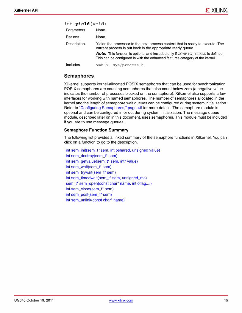
Xilkernel API
int yield(void)
Semaphores
Xilkernel supports kernel-allocated POSIX semaphores that can be used for synchronization. POSIX semaphores are counting semaphores that also count below zero (a negative value indicates the number of processes blocked on the semaphore). Xilkernel also supports a few interfaces for working with named semaphores. The number of semaphores allocated in the kernel and the length of semaphore wait queues can be configured during system initialization. Refer to “Configuring Semaphores,” page 46 for more details. The semaphore module is optional and can be configured in or out during system initialization. The message queue module, described later on in this document, uses semaphores. This module must be included if you are to use message queues.
Semaphore Function Summary
The following list provides a linked summary of the semaphore functions in Xilkernel. You can click on a function to go to the description.
Parameters None.
Returns None.
Description Yields the processor to the next process context that is ready to execute. The current process is put back in the appropriate ready queue.
Note: This function is optional and included only if CONFIG_YIELD is defined. This can be configured in with the enhanced features category of the kernel.
Includes xmk.h, sys/process.h
int sem_init(sem_t *sem, int pshared, unsigned value)int sem_destroy(sem_t* sem)int sem_getvalue(sem_t* sem, int* value)int sem_wait(sem_t* sem)int sem_trywait(sem_t* sem)int sem_timedwait(sem_t* sem, unsigned_ms)sem_t* sem_open(const char* name, int oflag,...)int sem_close(sem_t* sem)int sem_post(sem_t* sem)int sem_unlink(const char* name)
UG646 October 19, 2011 www.xilinx.com 15

Xilkernel API
Semaphore Function Descriptions
The following are descriptions of the Xilkernel semaphore functions:
int sem_init(sem_t *sem, int pshared, unsigned value)
int sem_destroy(sem_t* sem)
Parameters sem is the location at which to store the created semaphore’s identifier.pshared indicates sharing status of the semaphore, between processes.value is the initial count of the semaphore.
Note: pshared is unused currently.
Returns 0 on success.-1 on failure and sets errno appropriately. The errno is set to ENOSPC if no more semaphore resources are available in the system.
Description The sem_init( ) function initializes the unnamed semaphore referred to by sem. The value of the initialized semaphore is value. Following a successful call to sem_init( ), the semaphore can be used in subsequent calls to sem_wait( ), sem_trywait( ), sem_post( ), and sem_destroy( ). This semaphore remains usable until the semaphore is destroyed. Only sem itself can be used for performing synchronization. The result of referring to copies of sem in calls to sem_wait( ), sem_trywait( ), sem_post( ), and sem_destroy( ) is undefined. Attempting to initialize an already initialized semaphore results in undefined behavior.
Includes xmk.h, semaphore.h
Parameters sem is the semaphore to be destroyed.
Returns 0 on success.-1 on failure and sets errno appropriately. The errno can be set to:• EINVAL if the semaphore identifier does not refer to a valid semaphore.• EBUSY if the semaphore is currently locked, and processes are blocked on it.
Description The sem_destroy( ) function destroys the unnamed semaphore indicated by sem. Only a semaphore that was created using sem_init( ) can be destroyed using sem_destroy( ); the effect of calling sem_destroy( ) with a named semaphore is undefined. The effect of subsequent use of the semaphore sem is undefined until sem is re-initialized by another call to sem_init( ).
Includes xmk.h, semaphore.h
16 www.xilinx.com UG646 October 19, 2011

Xilkernel API
int sem_getvalue(sem_t* sem, int* value)
int sem_wait(sem_t* sem)
int sem_trywait(sem_t* sem)
Parameters sem is the semaphore identifier.value is the location where the semaphore value is stored.
Returns 0 on success and value appropriately filled in.-1 on failure and sets errno appropriately.The errno can be set to EINVAL if the semaphore identifier refers to an invalid semaphore.
Description The sem_getvalue( ) function updates the location referenced by the sval argument to have the value of the semaphore referenced by sem without affecting the state of the semaphore. The updated value represents an actual semaphore value that occurred at some unspecified time during the call, but it need not be the actual value of the semaphore when it is returned to the calling process.If sem is locked, then the object to which sval points is set to a negative number whose absolute value represents the number of processes waiting for the semaphore at some unspecified time during the call.
Includes xmk.h, semaphore.h
Parameters sem is the semaphore identifier.
Returns 0 on success and the semaphore in a locked state.-1 on failure and errno is set appropriately. The errno can be set to:• EINVAL if the semaphore identifier is invalid.• EIDRM if the semaphore was forcibly removed.
Description The sem_wait( ) function locks the semaphore referenced by sem by performing a semaphore lock operation on that semaphore. If the semaphore value is currently zero, then the calling thread does not return from the call to sem_wait( ) until it either locks the semaphore or the semaphore is forcibly destroyed.Upon successful return, the state of the semaphore is locked and remains locked until the sem_post( ) function is executed and returns successfully.
Note: When a process is unblocked within the sem_wait call, where it blocked due to unavailability of the semaphore, the semaphore might have been destroyed forcibly. In such a case, -1 is returned. Semaphores might be forcibly destroyed due to destroying message queues that use semaphores internally. No deadlock detection is provided.
Includes xmk.h, semaphore.h
Parameters sem is the semaphore identifier.
Returns 0 on success.-1 on failure and errno is set appropriately. The errno can be set to:• EINVAL if the semaphore identifier is invalid.• EAGAIN if the semaphore could not be locked immediately.
Description The sem_trywait( ) function locks the semaphore referenced by sem only if the semaphore is currently not locked; that is, if the semaphore value is currently positive. Otherwise, it does not lock the semaphore and returns -1.
Includes xmk.h, semaphore.h
UG646 October 19, 2011 www.xilinx.com 17

Xilkernel API
int sem_timedwait(sem_t* sem, unsigned_ms)Parameters sem is the semaphore identifier.
Returns 0 on success and the semaphore in a locked state.-1 on failure and errno is set appropriately. The errno can be set to:• EINVAL - If the semaphore identifier does not refer to a valid semaphore.• ETIMEDOUT - The semaphore could not be locked before the specified
timeout expired.• EIDRM - If the semaphore was forcibly removed from the system.
Description The sem_timedwait( ) function locks the semaphore referenced by sem by performing a semaphore lock operation on that semaphore. If the semaphore value is currently zero, then the calling thread does not return from the call to sem_timedwait( ) until one of the following conditions occurs:• It locks the semaphore. • The semaphore is forcibly destroyed.• The timeout specified has elapsed.Upon successful return, the state of the semaphore is locked and remains locked until the sem_post( ) function is executed and returns successfully.
Note: When a process is unblocked within the sem_wait call, where it blocked due to unavailability of the semaphore, the semaphore might have been destroyed forcibly. In such a case, -1 is returned. Semaphores maybe forcibly destroyed due to destroying message queues which internally use semaphores. No deadlock detection is provided.
Note: This routine depends on software timers support being present in the kernel and is defined only if CONFIG_TIME is true.
Note: This routine is slightly different from the POSIX equivalent. The POSIX version specifies the timeout as absolute wall-clock time. Because there is no concept of absolute time in Xilkernel, we use relative time specified in milliseconds.
Includes xmk.h, semaphore.h
18 www.xilinx.com UG646 October 19, 2011

Xilkernel API
sem_t* sem_open(const char* name, int oflag,...)
int sem_close(sem_t* sem)
Parameters name points to a string naming a semaphore object.
oflag is the flag that controls the semaphore creation.
Returns A pointer to the created/existing semaphore identifier.SEM_FAILED on failures and when errno is set appropriately. The errno can be set to:• ENOSPC - If the system is out of resources to create a new semaphore (or
mapping).• EEXIST - if O_EXCL has been requested and the named semaphore already
exists.• EINVAL - if the parameters are invalid.
Description The sem_open( ) function establishes a connection between a named semaphore and a process. Following a call to sem_open( ) with semaphore name, the process can reference the semaphore associated with name using the address returned from the call. This semaphore can be used in subsequent calls to sem_wait( ), sem_trywait( ), sem_post( ), and sem_close( ). The semaphore remains usable by this process until the semaphore is closed by a successful call to sem_close( ). The oflag argument controls whether the semaphore is created or merely accessed by the call to sem_open( ). The bits that can be set in oflag are:
♦ O_CREATUsed to create a semaphore if it does not already exist. If O_CREAT is set and the semaphore already exists, then O_CREAT has no effect, except as noted under O_EXCL. Otherwise, sem_open( ) creates a named semaphore. O_CREAT requires a third and a fourth argument: mode, which is of type mode_t, and value, which is of type unsigned.
♦ O_EXCLIf O_EXCL and O_CREAT are set, sem_open( ) fails if the semaphore name exists. The check for the existence of the semaphore and the creation of the semaphore if it does not exist are atomic with respect to other processes executing sem_open( ) with O_EXCL and O_CREAT set. If O_EXCL is set and O_CREAT is not set, the effect is undefined.
Note: The mode argument is unused currently. This interface is optional and is defined only if CONFIG_NAMED_SEMA is set to TRUE.
Note: If flags other than O_CREAT and O_EXCL are specified in the oflag parameter, an error is signalled.
The semaphore is created with an initial value of value. After the name semaphore has been created by sem_open( ) with the O_CREAT flag, other processes can connect to the semaphore by calling sem_open( ) with the same value of name.If a process makes multiple successful calls to sem_open( ) with the same value for name, the same semaphore address is returned for each such successful call, assuming that there have been no calls to sem_unlink( ) for this semaphore.
Includes xmk.h, semaphore.h
Parameters sem is the semaphore identifier.
Returns 0 on success.-1 on failure and sets errno appropriately. The errno can be set to:• EINVAL - If the semaphore identifier is invalid.• ENOTSUP - If the semaphore is currently locked and/or processes are blocked
on the semaphore.
UG646 October 19, 2011 www.xilinx.com 19

Xilkernel API
int sem_post(sem_t* sem)
Description The sem_close( ) function indicates that the calling process is finished using the named semaphore sem. The sem_close( ) function deallocates (that is, make available for reuse by a subsequent sem_open( ) by this process) any system resources allocated by the system for use by this process for this semaphore. The effect of subsequent use of the semaphore indicated by sem by this process is undefined. The name mapping for this named semaphore is also destroyed. The call fails if the semaphore is currently locked.
Note: This interface is optional and is defined only if CONFIG_NAMED_SEMA is true.
Includes xmk.h, semaphore.h
Parameters sem is the semaphore identifier.
Returns 0 on success.-1 on failure and sets errno appropriately. The errno can be set to EINVAL if the semaphore identifier is invalid.
Description The sem_post( ) function performs an unlock operation on the semaphore referenced by the sem identifier.If the semaphore value resulting from this operation is positive, then no threads were blocked waiting for the semaphore to become unlocked and the semaphore value is incremented.If the value of the semaphore resulting from this operation is zero or negative, then one of the threads blocked waiting for the semaphore is allowed to return successfully from its call to sem_wait( ). This is either the first thread on the queue, if scheduling mode is SCHED_RR or, it is the highest priority thread in the queue, if scheduling mode is SCHED_PRIO.
Note: If an unlink operation was requested on the semaphore, the post operation performs an unlink when no more processes are waiting on the semaphore.
Includes xmk.h, semaphore.h
20 www.xilinx.com UG646 October 19, 2011

Xilkernel API
int sem_unlink(const char* name)
Message Queues
Xilkernel supports kernel allocated X/Open System Interface (XSI) message queues. XSI is a set of optional interfaces under POSIX. Message queues can be used as an IPC mechanism. The message queues can take in arbitrary sized messages. However, buffer memory allocation must be configured appropriately for the memory blocks required for the messages, as a part of system buffer memory allocation initialization.The number of message queue structures allocated in the kernel and the length of the message queues can be also be configured during system initialization. The message queue module is optional and can be configured in/out. Refer to “Configuring Message Queues,” page 46 for more details. This module depends on the semaphore module and the dynamic buffer memory allocation module being present in the system. There is also a larger, but more powerful message queue functionality that can be configured if required. When the enhanced message queue interface is chosen, then malloc and free are used to allocate and free space for the messages. Therefore, arbitrary sized messages can be passed around without having to make sure that buffer memory allocation APIs can handle requests for arbitrary size.
Note: When using the enhanced message queue feature, you must choose your global heap size carefully, such that requests for heap memory from the message queue interfaces are satisfied without errors. You must also be aware of thread-safety issues when using malloc( ), free ( ) in your own code. You must disable interrupts and context switches before invoking the dynamic memory allocation routines. You must follow the same rules when using any other library routines that may internally use dynamic memory allocation.
Message Queue Function Summary
The following list provides a linked summary of the message queues in Xilkernel. You can click on a function to go to the description.
Parameters name is the name that refers to the semaphore.
Returns 0 on success.-1 on failure and errno is set appropriately. errno can be set to ENOENT - If an entry for name cannot be located.
Description The sem_unlink( ) function removes the semaphore named by the string name. If the semaphore named by name has processes blocked on it, then sem_unlink( ) has no immediate effect on the state of the semaphore. The destruction of the semaphore is postponed until all blocked and locking processes relinquish the semaphore. Calls to sem_open( ) to recreate or reconnect to the semaphore refer to a new semaphore after sem_unlink( ) is called. The sem_unlink( ) call does not block until all references relinquish the semaphore; it returns immediately.
Note: If an unlink operation had been requested on the semaphore, the unlink is performed on a post operation that sees that no more processes waiting on the semaphore. This interface is optional and is defined only if CONFIG_NAMED_SEMA is true.
Includes xmk.h, semaphore.h
int msgget(key_t key, int msgflg)int msgctl(int msqid, int cmd, struct msqid_ds* buf)int msgsnd(int msqid, const void *msgp, size_t msgsz, int msgflg)ssize_t msgrcv(int msqid, void *msgp, size_t nbytes, long msgtyp, int msgflg)
UG646 October 19, 2011 www.xilinx.com 21

Xilkernel API
Message Queue Function Descriptions
The Xilkernel message queue function descriptions are as follows:
int msgget(key_t key, int msgflg)Parameters key is a unique identifier for referring to the message queue.
msgflg specifies the message queue creation options.
Returns A unique non-negative integer message queue identifier.-1 on failure and sets errno appropriately; errno can be set to:
♦ EEXIST - If a message queue identifier exists for the argument key but ((msgflg and IPC_CREAT) and msgflg & IPC_EXCL) is non-zero.
♦ ENOENT - A message queue identifier does not exist for the argument key and (msgflg & IPC_CREAT) is 0.
♦ ENOSPC - If the message queue resources are exhausted.
Description The msgget( ) function returns the message queue identifier associated with the argument key. A message queue identifier, associated message queue, and data structure (see sys/kmsg.h), are created for the argument key if the argument key does not already have a message queue identifier associated with it, and (msgflg and IPC_CREAT) is non-zero.Upon creation, the data structure associated with the new message queue identifier is initialized as follows:
♦ msg_qnum, msg_lspid, msg_lrpid are set equal to 0.♦ msg_qbytes is set equal to the system limit (MSGQ_MAX_BYTES).
The msgget( ) function fails if a message queue identifier exists for the argument key but ((msgflg and IPC_CREAT) and (msgflg & IPC_EXCL)) is non-zero.IPC_PRIVATE is not supported. Also, messages in the message queue are not required to be of the form shown below. There is no support for message type based message receives and sends in this implementation.The following is an example code snippet:
struct mymsg {
..long mtype; /* Message type. */
..char mtext[some_size]; /* Message text. */
..}
Includes xmk.h, sys/msg.h, sys/ipc.h
22 www.xilinx.com UG646 October 19, 2011

Xilkernel API
int msgctl(int msqid, int cmd, struct msqid_ds* buf)Parameters msqid is the message queue identifier.
cmd is the command.buf is the data buffer
Returns 0 on success. Status is returned in buf for IPC_STAT.-1 on failure and sets errno appropriately. The errno can be set to EINVAL if any of the following conditions occur:• msgid parameter refers to an invalid message queue.• cmd is invalid.• buf contains invalid parameters.
Description The msgctl( ) function provides message control operations as specified by cmd. The values for cmd, and the message control operations they specify, are:• IPC_STAT - Places the current value of each member of the
msqid_ds data structure associated with msqid into the structure pointed to by buf. The contents of this structure are defined in sys/msg.h.
• IPC_SET - Unsupported.• IPC_RMID - Removes the message queue identifier specified by
msqid from the system and destroys the message queue and associated msqid_ds data structure. The remove operation forcibly destroys the semaphores used internally and unblocks processes that are blocked on the semaphore. It also deallocates memory allocated for the messages in the queue.
Includes xmk.h, sys/msg.h, sys/ipc.h
UG646 October 19, 2011 www.xilinx.com 23
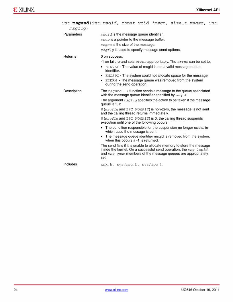
Xilkernel API
int msgsnd(int msqid, const void *msgp, size_t msgsz, int msgflg)
Parameters msqid is the message queue identifier.msgp is a pointer to the message buffer.msgsz is the size of the message.msgflg is used to specify message send options.
Returns 0 on success.-1 on failure and sets errno appropriately. The errno can be set to:• EINVAL - The value of msgid is not a valid message queue
identifier.• ENOSPC - The system could not allocate space for the message.• EIDRM - The message queue was removed from the system
during the send operation.
Description The msgsnd( ) function sends a message to the queue associated with the message queue identifier specified by msqid.The argument msgflg specifies the action to be taken if the message queue is full:If (msgflg and IPC_NOWAIT) is non-zero, the message is not sent and the calling thread returns immediately.If (msgflg and IPC_NOWAIT) is 0, the calling thread suspends execution until one of the following occurs:• The condition responsible for the suspension no longer exists, in
which case the message is sent.• The message queue identifier msqid is removed from the system;
when this occurs a -1 is returned.The send fails if it is unable to allocate memory to store the message inside the kernel. On a successful send operation, the msg_lspid and msg_qnum members of the message queues are appropriately set.
Includes xmk.h, sys/msg.h, sys/ipc.h
24 www.xilinx.com UG646 October 19, 2011

Xilkernel API
ssize_t msgrcv(int msqid, void *msgp, size_t nbytes, long msgtyp, int msgflg)
Parameters msqid is the message queue identifier.msgp is the buffer where the received message is to be copied.nbytes specifies the size of the message that the buffer can hold.msgtyp is currently unsupported.msgflg is used to control the message receive operation.
Returns On success, stores received message in user buffer and returns number of bytes of data received.-1 on failure and sets errno appropriately. The errno can be set to:• EINVAL - If msgid is not a valid message queue identifier.• EIDRM - If the message queue was removed from the system.• ENOMSG - msgsz is smaller than the size of the message in the
queue.
Description The msgrcv( ) function reads a message from the queue associated with the message queue identifier specified by msqid and places it in the user-defined buffer pointed to by msgp.The argument msgsz specifies the size in bytes of the message. The received message is truncated to msgsz bytes if it is larger than msgsz and (msgflg and MSG_NOERROR) is non-zero. The truncated part of the message is lost and no indication of the truncation is given to the calling process. If MSG_NOERROR is not specified and the received message is larger than nbytes, then a -1 is returned signalling error.The argument msgflg specifies the action to be taken if a message is not on the queue. These are as follows:• If (msgflg and IPC_NOWAIT) is non-zero, the calling thread
returns immediately with a return value of -1.• If (msgflg and IPC_NOWAIT) is 0, the calling thread suspends
execution until one of the following occurs:♦ A message is placed on the queue♦ The message queue identifier msqid is removed from the
system; when this occurs -1 is returnedUpon successful completion, the following actions are taken with respect to the data structure associated with msqid:• msg_qnum is decremented by 1.• msg_lrpid is set equal to the process ID of the calling process.
Includes xmk.h, sys/msg.h, sys/ipc.h
UG646 October 19, 2011 www.xilinx.com 25

Xilkernel API
Shared Memory
Xilkernel supports kernel-allocated XSI shared memory. XSI is the X/Open System Interface which is a set of optional interfaces under POSIX. Shared memory is a common, low-latency IPC mechanism. Shared memory blocks required during run-time must be identified and specified during the system configuration. From this specification, buffer memory is allocated to each shared memory region. Shared memory is currently not allocated dynamically at run-time. This module is optional and can be configured in or out during system specification. Refer to “Configuring Shared Memory,” page 47 for more details.
Shared Memory Function Summary
The following list provides a linked summary of the shared memory functions in Xilkernel. You can click on a function to go to the description.
Shared Memory Function Descriptions
The Xilkernel shared memory interface is described below.
Caution! The memory buffers allocated by the shared memory API might not be aligned at word boundaries. Therefore, structures should not be arbitrarily mapped to shared memory segments, without checking if alignment requirements are met.
int shmget(key_t key, size_t size, int shmflg)int shmctl(int shmid, int cmd, struct shmid_ds *buf)void* shmat(int shmid, const void *shmaddr, int flag)int shm_dt(void *shmaddr)
26 www.xilinx.com UG646 October 19, 2011

Xilkernel API
int shmget(key_t key, size_t size, int shmflg)
int shmctl(int shmid, int cmd, struct shmid_ds *buf)
Parameters key is used to uniquely identify the shared memory region.size is the requested size of the shared memory segment.shmflg specifies segment creation options.
Returns Unique non-negative shared memory identifier on success.-1 on failure and sets errno appropriately: errno can be set to:
♦ EEXIST - A shared memory identifier exists for the argument key but (shmflg and IPC_CREAT) and (shmflg and IPC_EXCL) is non-zero.
♦ ENOTSUP - Unsupported shmflg.♦ ENOENT - A shared memory identifier does not exist for the argument
key and (shmflg and IPC_CREAT) is 0.
Description The shmget( ) function returns the shared memory identifier associated with key. A shared memory identifier, associated data structure, and shared memory segment of at least size bytes (see sys/shm.h) are created for key if one of the following is true:
♦ key is equal to IPC_PRIVATE.♦ key does not already have a shared memory identifier associated
with it and (shmflg and IPC_CREAT) is non-zero.Upon creation, the data structure associated with the new shared memory identifier shall be initialized.The value of shm_segsz is set equal to the value of size. The values of shm_lpid, shm_nattch, shm_cpid are all initialized appropriately. When the shared memory segment is created, it is initialized with all zero values. At least one of the shared memory segments available in the system must match exactly the requested size for the call to succeed. Key IPC_PRIVATE is not supported.
Includes xmk.h, sys/shm.h, sys/ipc.h
Parameters shmid is the shared memory segment identifier.cmd is the command to the control function.buf is the buffer where the status is returned.
Returns 0 on success. Status is returned in buffer for IPC_STAT.-1 on failure and sets errno appropriately: errno can be set to EINVAL on the following conditions:• if shmid refers to an invalid shared memory segment. • if cmd or other params are invalid.
Description The shmctl( ) function provides a variety of shared memory control operations as specified by cmd. The following values for cmd are available:• IPC_STAT: places the current value of each member of the shmid_ds
data structure associated with shmid into the structure pointed to by buf. The contents of the structure are defined in sys/shm.h.
• IPC_SET is not supported.• IPC_RMID: removes the shared memory identifier specified by shmid
from the system and destroys the shared memory segment and shmid_ds data structure associated with it. No notification is sent to processes still attached to the segment.
Includes xmk.h, sys/shm.h, sys/ipc.h
UG646 October 19, 2011 www.xilinx.com 27

Xilkernel API
void* shmat(int shmid, const void *shmaddr, int flag)
int shm_dt(void *shmaddr)
Mutex Locks
Xilkernel provides support for kernel allocated POSIX thread mutex locks. This synchronization mechanism can be used alongside of the pthread_ API. The number of mutex locks and the length of the mutex lock wait queue can be configured during system specification. PTHREAD_MUTEX_DEFAULT and PTHREAD_MUTEX_RECURSIVE type mutex locks are supported. This module is also optional and can be configured in or out during system specification. Refer to “Configuring Shared Memory,” page 47 for more details.
Mutex Lock Function Summary
The following list provides a linked summary of the Mutex locks in Xilkernel. You can click on a function to go to the description.
Parameters shmid is the shared memory segment identifier.shmaddr is used to specify the location, to attach shared memory segment. This is currently unused.flag is used to specify shared memory (SHM) attach options.
Returns The start address of the shared memory segment on success.NULL on failure and sets errno appropriately. errno can be set to EINVAL if shmid refers to an invalid shared memory segment
Description shmat( ) increments the value of shm_nattch in the data structure associated with the shared memory ID of the attached shared memory segment and returns the start address of the segment. shm_lpid is also appropriately set.
Note: shmaddr and flag arguments are not used.
Includes xmk.h, sys/shm.h, sys/ipc.h
Parameters shmaddr is the shared memory segment address that is to be detached.
Returns 0 on success.-1 on failure and sets errno appropriately. The errno can be set to EINVAL if shmaddr is not within any of the available shared memory segments.
Description The shmdt( ) function detaches the shared memory segment located at the address specified by shmaddr from the address space of the calling process. The value of shm_nattch is also decremented. The memory segment is not removed from the system and can be attached to again.
Includes xmk.h, sys/shm.h, sys/ipc.h
int pthread_mutex_init(pthread_mutex_t* mutex, const pthread_mutexattr_t* attr)int pthread_mutex_destroy(pthread_mutex_t* mutex)int pthread_mutex_lock(pthread_mutex_t* mutex)int pthread_mutex_trylock(pthread_mutex_t* mutex)int pthread_mutex_unlock(pthread_mutex_t* mutex)int pthread_mutexattr_init(pthread_mutexattr_t* attr)int pthread_mutexattr_destroy(pthread_mutexattr_t* attr)int pthread_mutexattr_settype(pthread_mutexattr_t* attr, int type)int pthread_mutexattr_gettype(pthread_mutexattr_t* attr, int *type)
28 www.xilinx.com UG646 October 19, 2011

Xilkernel API
Mutex Lock Function Descriptions
The Mutex lock function descriptions are as follows:
int pthread_mutex_init(pthread_mutex_t* mutex, const pthread_mutexattr_t* attr)
Note: The mutex locks allocated by Xilkernel follow the semantics of PTHREAD_MUTEX_DEFAULT mutex locks by default. The following actions will result in undefined behavior:
- Attempting to recursively lock the mutex.
- Attempting to unlock the mutex if it was not locked by the calling thread.
- Attempting to unlock the mutex if it is not locked.
Parameters mutex is the location where the newly created mutex lock’s identifier is to be stored.attr is the mutex creation attributes structure.
Returns 0 on success and mutex identifier in *mutex.EAGAIN if system is out of resources.
Description The pthread_mutex_init( ) function initializes the mutex referenced by mutex with attributes specified by attr. If attr is NULL, the default mutex attributes are used; the effect is the same as passing the address of a default mutex attributes object. Refer to the pthread_mutexattr_ routines, which are documented starting on page 32 to determine what kind of mutex creation attributes can be changed. Upon successful initialization, the state of the mutex becomes initialized and unlocked. Only the mutex itself can be used for performing synchronization. The result of referring to copies of mutex in calls to pthread_mutex_lock( ), pthread_mutex_trylock( ), pthread_mutex_unlock( ), and pthread_mutex_destroy( ) is undefined.Attempting to initialize an already initialized mutex results in undefined behavior. In cases where default mutex attributes are appropriate, the macro PTHREAD_MUTEX_INITIALIZER can be used to initialize mutexes that are statically allocated. The effect is equivalent to dynamic initialization by a call to pthread_mutex_init( ) with parameter attr specified as NULL, with the exception that no error checks are performed.For example:
static pthread_mutex_t foo_mutex = PTHREAD_MUTEX_INITIALIZER;
Includes xmk.h, pthread.h
UG646 October 19, 2011 www.xilinx.com 29

Xilkernel API
int pthread_mutex_destroy(pthread_mutex_t* mutex)
int pthread_mutex_lock(pthread_mutex_t* mutex)
Parameters mutex is the mutex identifier.
Returns 0 on success.EINVAL if mutex refers to an invalid identifier.
Description The pthread_mutex_destroy( ) function destroys the mutex object referenced by mutex; the mutex object becomes, in effect, uninitialized. A destroyed mutex object can be reinitialized using pthread_mutex_init( ); the results of otherwise referencing the object after it has been destroyed are undefined.
Note: Mutex lock/unlock state disregarded during destroy. No consideration is given for waiting processes.
Includes xmk.h, pthread.h
Parameters mutex is the mutex identifier.
Returns 0 on success and mutex in a locked state.EINVAL on invalid mutex reference. -1 on unhandled errors.
Description The mutex object referenced by mutex is locked by the thread calling pthread_mutex_lock( ). If the mutex is already locked, the calling thread blocks until the mutex becomes available. If the mutex type is PTHREAD_MUTEX_RECURSIVE, then the mutex maintains the concept of a lock count. When a thread successfully acquires a mutex for the first time, the lock count is set to one. Every time a thread relocks this mutex, the lock count is incremented by one. Each time the thread unlocks the mutex, the lock count is decremented by one.If the mutex type is PTHREAD_MUTEX_DEFAULT, attempting to recursively lock the mutex results in undefined behavior. If successful, this operation returns with the mutex object referenced by mutex in the locked state.
Includes xmk.h, pthread.h
30 www.xilinx.com UG646 October 19, 2011

Xilkernel API
int pthread_mutex_trylock(pthread_mutex_t* mutex)
int pthread_mutex_unlock(pthread_mutex_t* mutex)
Parameters mutex is the mutex identifier.
Returns 0 on success. mutex in a locked state.EINVAL on invalid mutex reference, EBUSY if mutex is already locked.-1 on unhandled errors.
Description The mutex object referenced by mutex is locked by the thread calling pthread_mutex_trlock( ). If the mutex is already locked, the calling thread returns immediately with EBUSY. If the mutex type is PTHREAD_MUTEX_RECURSIVE, then the mutex maintains the concept of a lock count. When a thread successfully acquires a mutex for the first time, the lock count is set to one. Every time a thread relocks this mutex, the lock count is incremented by one. Each time the thread unlocks the mutex, the lock count is decremented by one.If the mutex type is PTHREAD_MUTEX_DEFAULT, attempting to recursively lock the mutex results in undefined behavior. If successful, this operation returns with the mutex object referenced by mutex in the locked state.
Includes xmk.h, pthread.h
Parameters mutex is the mutex identifier.
Returns 0 on success, EINVAL on invalid mutex reference.-1 on undefined errors.
Description The pthread_mutex_unlock( ) function releases the mutex object referenced by mutex. If there are threads blocked on the mutex object referenced by mutex when pthread_mutex_unlock( ) is called, resulting in the mutex becoming available, the scheduling policy determines which thread will acquire the mutex. If it is SCHED_RR, then the thread that is at the head of the mutex wait queue is unblocked and allowed to lock the mutex.
If the mutex type is PTHREAD_MUTEX_RECURSIVE, the mutex maintains the concept of a lock count. When the lock count reaches zero, the mutex becomes available for other threads to acquire. If a thread attempts to unlock a mutex that it has not locked or a mutex which is unlocked, an error is returned.
If the mutex type is PTHREAD_MUTEX_DEFAULT the following actions result in undefined behavior:
• Attempting to unlock the mutex if it was not locked by the calling thread.
• Attempting to unlock the mutex if it is not locked.
If successful, this operation returns with the mutex object referenced by mutex in the unlocked state.
Includes xmk.h, pthread.h
UG646 October 19, 2011 www.xilinx.com 31

Xilkernel API
int pthread_mutexattr_init(pthread_mutexattr_t* attr)
int pthread_mutexattr_destroy(pthread_mutexattr_t* attr)
int pthread_mutexattr_settype(pthread_mutexattr_t* attr, int type)
Parameters attr is the location of the attributes structure.
Returns 0 on success.EINVAL if attr refers to an invalid location.
Description The pthread_mutexattr_init( ) function initializes a mutex attributes object attr with the default value for all of the attributes defined by the implementation.Refer to sys/types.h for the contents of the pthread_mutexattr structure.
Note: This routine does not involve a call into the kernel.
Includes xmk.h, pthread.h
Parameters attr is the location of the attributes structure.
Returns 0 on success.EINVAL if attr refers to an invalid location.
Description The pthread_mutexattr_destroy( ) function destroys a mutex attributes object; the object becomes, in effect, uninitialized.
Note: This routine does not involve a call into the kernel.
Includes xmk.h, pthread.h
Parameters attr is the location of the attributes structure.type is the type to which to set the mutex.
Returns 0 on success.EINVAL if attr refers to an invalid location or if type is an unsupported type.
Description The pthread_mutexattr_settype( ) function sets the type of a mutex in a mutex attributes structure to the specified type. Only PTHREAD_MUTEX_DEFAULT and PTHREAD_MUTEX_RECURSIVE are supported.
Note: This routine does not involve a call into the kernel.
Includes xmk.h, pthread.h
32 www.xilinx.com UG646 October 19, 2011

Xilkernel API
int pthread_mutexattr_gettype(pthread_mutexattr_t* attr, int *type)
Dynamic Buffer Memory Management
The kernel provides a buffer memory allocation scheme, which can be used by applications that need dynamic memory allocation. These interfaces are alternatives to the standard C memory allocation routines - malloc( ), free( ) which are much slower and bigger, though more powerful. The allocation routines hand off pieces of memory from a pool of memory that the user passes to the buffer memory manager.
The buffer memory manager manages the pool of memory. You can dynamically create new pools of memory. You can also statically specify the different memory blocks sizes and number of such memory blocks required for your applications. Refer to “Configuring Buffer Memory Allocation,” page 47 for more details. This method of buffer management is relatively simple, small and a fast way of allocating memory. The following are the buffer memory allocation interfaces. This module is optional and can be included during system initialization.
Dynamic Buffer Memory Management Function Summary
The following list provides a linked summary of the dynamic buffer memory management functions in Xilkernel. You can click on a function to go to the description.
Caution! The buffer memory allocation API internally uses the memory pool handed down the by the user to store a free-list in-place within the memory pool. As a result, only memory sizes greater than or equal to 4 bytes long are supported by the buffer memory allocation APIs. Also, because there is a free-list being built in-place within the memory pool, requests in which memory block sizes are not multiples of 4 bytes cause unalignment at run time. If your software platform can handle unalignment natively or through exceptions then this does not present an issue. The memory buffers allocated and returned by the buffer memory allocation API might also not be aligned at word boundaries. Therefore, your application should not arbitrarily map structures to memory allocated in this way without first checking if alignment and padding requirements are met.
Parameters attr is the location of the attributes structure.type is a pointer to the location at which to store the mutex.
Returns 0 on success.EINVAL if attr refers to an invalid location.
Description The pthread_mutexattr_gettype( ) function gets the type of a mutex in a mutex attributes structure and stores it in the location pointed to by type.
Includes xmk.h, pthread.h
int bufcreate(membuf_t *mbuf, void *memptr, int nblks, size_t blksiz)int bufdestroy(membuf_t mbuf)void* bufmalloc(membuf_t mbuf, size_t siz)void buffree(membuf_t mbuf, void* mem)
UG646 October 19, 2011 www.xilinx.com 33

Xilkernel API
Dynamic Buffer Memory Management Function Descriptions
The dynamic buffer memory management function descriptions are as follows:
int bufcreate(membuf_t *mbuf, void *memptr, int nblks, size_t blksiz)
int bufdestroy(membuf_t mbuf)
void* bufmalloc(membuf_t mbuf, size_t siz)
Parameters mbuf is location at which to store the identifier of the memory pool created.memptr is the pool of memory to use.nblks is the number of memory blocks that this pool should support. blksiz is the size of each memory block in bytes.
Returns 0 on success and stores the identifier of the created memory pool in the location pointed to by mbuf.-1 on errors.
Description Creates a memory pool out of the memory block specified in memptr. nblks number of chunks of memory are defined within the pool, each of size blksiz. Therefore, memptr must point to at least (nblks * blksiz) bytes of memory. blksiz must be greater than or equal to 4.
Includes xmk.h, sys/bufmalloc.h
Parameters mbuf is the identifier of the memory pool to destroy.
Returns 0 on success.-1 on errors.
Description This routine destroys the memory pool identified by mbuf.
Includes xmk.h, sys/bufmalloc.h
Parameters mbuf is the identifier of the memory pool from which to allocate memory.size is the size of memory block requested.
Returns The start address of the memory block on success.NULL on failure and sets errno appropriately: errno is set to:• EINVAL if mbuf refers to an invalid memory buffer.• EAGAIN if the request cannot be satisfied.
Description Allocate a chunk of memory from the memory pool specified by mbuf. If mbuf is MEMBUF_ANY, then all available memory pools are searched for the request and the first pool that has a free block of size siz, is used and allocated from.
Includes xmk.h, sys/bufmalloc.h
34 www.xilinx.com UG646 October 19, 2011

Xilkernel API
void buffree(membuf_t mbuf, void* mem)
Software Timers
Xilkernel provides software timer functionality, for time relating processing. This module is optional and can be configured in or out. Refer to “Configuring Software Timers,” page 48 for more information on customizing this module.
The following list provides a linked summary of the interfaces are available with the software timers module. You can click on a function to go to the description.
unsigned int xget_clock_ticks( )
time_t time(time_t *timer)
Parameters mbuf is the identifier of the memory pool.mem is the address of the memory block.
Returns None.
Description Frees the memory allocated by a corresponding call to bufmalloc. If mbuf is MEMBUF_ANY, returns the memory to the pool that satisfied this request. If not, returns the memory to specified pool. Behavior is undefined if arbitrary values are specified for mem.
Includes xmk.h, sys/bufmalloc.h
unsigned int xget_clock_ticks( )
Parameters None.
Returns Number of kernel ticks elapsed since the kernel was started.
Description A single tick is counted, every time the kernel timer delivers an interrupt. This is stored in a 32-bit integer and eventually overflows. The call to xget_clock_ticks( ) returns this tick information, without conveying the overflows that have occurred.
Includes xmk.h, sys/timer.h
Parameters timer points to the memory location in which to store the requested time information.
Returns Number of seconds elapsed since the kernel was started.
Description The routine time elapsed since kernel start in units of seconds. This is also subject to overflow.
Includes xmk.h, sys/timer.h
UG646 October 19, 2011 www.xilinx.com 35

Interrupt Handling
unsigned sleep(unsigned int ms)
Interrupt Handling
Xilkernel abstracts away primary interrupt handling requirements from the user application. Even though the kernel is functional without any interrupts, the system only makes sense when it is driven by at least one timer interrupt for scheduling. The kernel handles the main timer interrupt, using it as the kernel tick to perform scheduling. The timer interrupt is initialized and tied to the vectoring code during system initialization. This kernel pulse provides software timer facilities and time-related routines also. Additionally, Xilkernel can handle multiple interrupts when connected through an interrupt controller, and works with the xps_intc or axi_intc interrupt controller core. The following figure shows a basic interrupt service in Xilkernel.
The interrupt handling scenario is illustrated in this diagram. Upon an interrupt:
• The context of the currently executing process is saved into the context save area.
• Interrupts are disabled from this point in time onwards, until they are enabled at the end of interrupt handling.
• This alleviates the stack burden of the process, as the execution within interrupt, does not use the user application stack.
• This interrupt context can be thought of as a special kernel thread that executes interrupt handlers in order. This thread starts to use its own separate execution stack space.
• The separate kernel execution stack is at-least 1 KB in size to enable it to handle deep levels of nesting within interrupt handlers. This kernel stack is also automatically configured to use the pthread stack size chosen by the user, if it is larger than 1 KB. If you foresee a large stack usage within your interrupt handlers, you will need to specify a large value for pthread_stack_size.
This ends the first level of interrupt handling by the kernel. At this point, the kernel transfers control to the second level interrupt handler. This is the main interrupt handler routine of the
Parameters ms is the number of milliseconds to sleep.
Returns Number of seconds between sleeps.0 on complete success.
Description This routine causes the invoking process to enter a sleep state for the specified number of milliseconds.
Includes xmk.h, sys/timer.h
X-Ref Target - Figure 5
Figure 5: Basic Interrupt Service in Xilkernel
IE = 1
IE = 1
IE = 0 -Save complete context;-Switch to kernel IRQ stack;-Execute next level of interrupt handling.-If rescheduling is required, invoke the scheduler.-Restore context of the currently selected process.
Executing processgets interrupted
X10229
IE = 1
Resumed processproceeds
Execute user levelinterrupts if any
36 www.xilinx.com UG646 October 19, 2011

Interrupt Handling
interrupt controller. From this point, the handler for the interrupt controller invokes the user-specified interrupt handlers for the various interrupting peripherals.
In MicroBlaze processor kernels, if the system timer is connected through the interrupt controller, then the kernel invisibly handles the main timer interrupt (kernel tick), by registering itself as the handler for that interrupt.
Interrupt handlers can perform any kind of required interrupt handling action, including making system calls. However, the handlers must never invoke blocking system calls, or the entire kernel is blocked and the system comes to a suspended state. Use handlers wisely to do minimum processing upon interrupts.
Caution! User level interrupt handlers must not make blocking system calls. System calls made, if any, should be non-blocking.
After the user-level interrupt handlers are serviced, the first-level interrupt handler in the kernel gets control again. It determines if the preceding interrupt handling caused a rescheduling requirement in the kernel.
If there is such a requirement, it invokes the kernel scheduler and performs the appropriate rescheduling. After the scheduler has determined the next process to execute, the context of the new process is restored and interrupts are enabled again.
Note: Currently, Xilkernel only supports an interrupt controller tied to the external interrupt pin of the PowerPC 405 processor. It does not support interrupt controllers tied to the critical input pin of the processor.
When Xilkernel is used with multiple-interrupts in the system, the Xilkernel user-level interrupt handling API becomes available. The following subsection lists user-level interrupt handling APIs.
UG646 October 19, 2011 www.xilinx.com 37

Interrupt Handling
User-Level Interrupt Handling APIs
User-Level Interrupt Handling APIs Function Summary
The following list provides a linked summary of the user-level interrupt handling APIs in Xilkernel. You can click on a function to go to the description.
User-Level Interrupt Handling APIs Function Descriptions
The interrupt handlings API descriptions are as follows:
unsigned int register_int_handler(int_id_t id, void *handler)(void*), void *callback)
void unregister_int_handler(int_id_t id)
unsigned int register_int_handler(int_id_t id, void *handler)(void*), void *callback)void unregister_int_handler(int_id_t id)void enable_interrupt(int_id_t id)void disable_interrupt(int_id_t id)void acknowledge_interrupt(int_id_t id)
Parameters id is the zero-based numeric id of the interrupt.handler is the user-level handler.callback is a callback value that can be delivered to the user-level handler.
Returns XST_SUCCESS on success.error codes defined in xstatus.h.
Description The register_int_handler( ) function registers the specified user level interrupt handler as the handler for a specified interrupt. The user level routine is invoked asynchronously upon being serviced by an interrupt controller in the system. The routine returns an error on MicroBlaze processor systems if id is the identifier for the system timer interrupt. PowerPC processor systems have a dedicated hardware timer interrupt that exists separately from the other interrupts in the system. Therefore, this check is not performed for a PowerPC processor system.
Includes xmk.h, sys/intr.h
Parameters id is the zero-based numeric id of the interrupt.
Returns None.
Description The unregister_int_handler( ) function unregisters the registered user-level interrupt handler as the handler for the specified interrupt. The routine does nothing and fails silently on MicroBlaze processor systems if id is the identifier for the system timer interrupt.
Includes xmk.h, sys/intr.h
38 www.xilinx.com UG646 October 19, 2011

Exception Handling
void enable_interrupt(int_id_t id)
void disable_interrupt(int_id_t id)
void acknowledge_interrupt(int_id_t id)
Exception Handling
Xilkernel handles exceptions for the MicroBlaze processor, treating them as faulting conditions by the executing processes/threads. Xilkernel kills the faulting process and reports using a message to the console (if verbose mode is on) as to the nature of the exception. You cannot register your own handlers for these exceptions and Xilkernel handles them all natively.
Xilkernel does not handle exceptions for the PowerPC processor. The exception handling API and model that is available for the Standalone platform is available for Xilkernel. You might want to register handlers or set breakpoints (during debug) for exceptions that are of interest to you.
Memory Protection
Memory protection is an extremely useful feature that can increase the robustness, reliability, and fault tolerance of your Xilkernel-based application. Memory protection requires support from the hardware. Xilkernel is designed to make use of the MicroBlaze Memory Management (Protection) Unit (MMU) features when available. This allows you to build fail-safe applications that each run within the valid sandbox of the system, as determined by the executable file and available I/O devices.
Note: Full virtual memory management is not supported by Xilkernel. Even when a full MMU is available on a MicroBlaze processor, only transparent memory translations are used, and there is no concept of demand paging.
Note: Xilkernel does not support the Memory Protection feature on PowerPC processors.
Parameters id is the zero-based numeric id of the interrupt.
Returns None.
Description The enable_interrupt( ) function enables the specified interrupt in the interrupt controller. The routine does nothing and fails silently on MicroBlaze processor systems, if id is the identifier for the system timer interrupt.
Includes xmk.h, sys/intr.h
Parameters id is the zero-based numeric id of the interrupt.
Returns None.
Description The disable_interrupt( ) function disables the specified interrupt in the interrupt controller. The routine does nothing and fails silently on MicroBlaze processor systems if id is the identifier for the system timer interrupt.
Includes xmk.h, sys/intr.h
Parameters id is the zero-based numeric identifier of the interrupt.
Returns None.
Description The acknowledge_interrupt( ) function acknowledges handling the specified interrupt to the interrupt controller. The routine does nothing and fails silently on MicroBlaze processor systems if id is the identifier for the system timer interrupt.
Includes xmk.h, sys/intr.h
UG646 October 19, 2011 www.xilinx.com 39

Memory Protection
Memory Protection Overview
When the MicroBlaze parameter C_USE_MMU is set to >=2, the kernel configures in memory protection during startup automatically.
Note: To disable the memory protection in the kernel, add the compiler flag -D XILKERNEL_MB_MPU_DISABLE, to your library and application build.
The kernel identifies three types of protection violations:
1. Code violation — occurs when a thread tries to execute from memory that is not defined to contain program instructions.
Note: Because Xilkernel is a single executable, all threads have access to all program instructions and the kernel cannot trap violations where a thread starts executing the kernel code directly.
2. Data access violation — Occurs when a thread tries to read or write data to or from memory that is not defined to be a part of the program data space. Similarly, read-only data segments can be protected by write access by all threads.
Note: Because Xilkernel is a single executable, all threads have equal access to all data as well as the kernel data structures. The kernel cannot trap violations where a thread accesses data that it is not designated to handle.
3. I / O violation — occurs when a thread tries to read or write from memory-mapped peripheral I / O space that is not present in the system.
Xilkernel attempts to determine these three conceptual protection areas in your program and system during system build and kernel boot time automatically. The kernel attempts to identify code and data labels that demarcate code and data sections in your executable ELF file. These labels are typically provided by linker scripts.
For example, MicroBlaze linker scripts use the labels _ftext and _etext to indicate the beginning and the end of the .text section respectively.
The following table summarizes the logical sections that must be present in the linker script, the requirements on the alignment of each section, and the demarcating labels.
Each section must be aligned at 1 KB boundary and clearly demarcated by the specified labels. Otherwise, Xilkernel will ignore the missing logical sections with no error or warning message.
Caution! This behavior could manifest itself in your software not working as expected, because MPU translation entries will be missing for important ELF sections and the processor will treat valid requests as invalid.
Table 1: Linker Script Logical Sections
Section Start Label End Label Description
.text _ftext _etext Executable instruction sections
.data _fdata _edata Read-write data sections including small data sections
.rodata _frodata _erodata Read only data sections including small data sections
.stack _stack_end _stack Kernel stack with 1 KB guard page above and below
stack guard page (top)
_fstack_guard_top _estack_guard_top Top kernel stack guard page (1 KB)
stack guard page (bottom)
_fstack_guard_bottom
_estack_guard_bottom
Bottom kernel stack guard page (1 KB)
40 www.xilinx.com UG646 October 19, 2011

Memory Protection
Note: Each section typically has a specific type of data that is expected to be present. If the logic of the data inserted into the sections by your linker script is inappropriate, then the protection offered by the kernel could be incorrect or the level of protection could be diluted.
I/O ranges are automatically enumerated by the library generation tools and provided as a data structure to the kernel. These peripheral I/O ranges will not include read/write memory areas because the access controls for memory are determined automatically from the ELF file. During kernel boot, the enumerated I/O ranges are marked as readable and writable by the threads. Accesses outside of the defined I/O ranges causes a protection fault.
User-specified Protection
In addition to the automatic inference and protection region setup done by the kernel, you can provide your own protection regions by providing the data structures as shown in the following example. If this feature is not required, these data structures can be removed from the application code.
#include <mpu.h>
int user_io_nranges = 2;xilkernel_io_range_t user_io_range[1] = {{0x25004000, 0x25004fff, MPU_PROT_READWRITE},
{0x44000000, 0x44001fff, MPU_PROT_NONE}};
The xilkernel_io_ranges_t type is defined as follows:
typedef struct xilkernel_io_range_s { unsigned int baseaddr; unsigned int highaddr; unsigned int flags;} xilkernel_io_range_t;
The following table lists the valid field flags that identify the user-specified access protection options:
Fixed Unified Translation Look-aside Buffer (TLB) Support on the MicroBlaze Processor
The MicroBlaze processor has a fixed 64-entry Unified Translation Look-aside Buffer (TLB). Xilkernel can support up to this maximum number of TLBs only. If the maximum TLBs to enable protection for a given region are exceeded, Xilkernel will report an error during Microprocessor Unit (MPU) initialization and proceed to boot the kernel without memory protection. There is no support for dynamically swapping TLB management to provide an arbitrary number of protection regions.
Table 2: Access Protection Field Flags
Field Flag Description
MPU_PROT_EXEC Executable program instructions (no read or write permissions)
MPU_PROT_READWRITE Readable and writable data sections (no execute permissions)
MPU_PROT_READ Read-only data sections (no write/execute permissions)
MPU_PROT_NONE (Currently no page can be protected from all three accesses at the same time. This field flag is equivalent to MPU_PROT_READ)
UG646 October 19, 2011 www.xilinx.com 41

Other Interfaces
Other Interfaces Internally, Xilkernel, depends on the Standalone platform; consequently, the interfaces that the Standalone presents are inherited by Xilkernel. Refer to the “Standalone” document for information on available interfaces. For example, to add your own custom handlers for the various exceptions that PowerPC 405 processor supports, you would use the exception handling interface provided by the Standalone for the PowerPC 405 processor.
Hardware Requirements
Xilkernel has been designed to work with the EDK hardware and software flow. It is completely integrated with the software platform configuration and automatic library generation mechanism. As a result, a software platform based on Xilkernel can be configured and built in a matter of minutes. However, some services in the kernel require support from the hardware. Scheduling and all the dependent features require a periodic kernel tick and typically some kind of timer is used. Xilkernel has been designed to work with either the Xilinx fit_timer IP core or the xps_timer/axi_timer IP core. By specifying the instance name of the timer device in the software platform configuration, Xilkernel is able to initialize and use the timer cores and timer related services automatically. Refer to “Configuring System Timer,” page 48 for more information on how to specify the timer device. On PowerPC 405 and PowerPC 440 processors, Xilkernel uses the internal programmable timer of the processor and consequently does not need external timer cores for kernel functionality; you must, however, specify values for the system timer frequency and system timer interval.
Xilkernel has also been designed to work in scenarios involving multiple-interrupting peripherals. The xps_intc/axi_intc IP core handles the hardware interrupts and feeds a single IRQ line from the controller to the processor. By specifying the name of the interrupt controller peripheral in the software platform configuration, you would be getting kernel awareness of multiple interrupts. Xilkernel would automatically initialize the hardware cores, interrupt system, and the second level of software handlers as a part of its startup. You do not have to do this manually. Xilkernel handles non-cascaded interrupt controllers; cascaded interrupt controllers are not supported.
System Initialization
The entry point for the kernel is the xilkernel_main( ) routine defined in main.c. Any user initialization that must be performed can be done before the call to xilkernel_main( ). This includes any system-wide features that might need to be enabled before invoking xilkernel_main( ). These are typically machine-state features such as cache enablement or hardware exception enablement that must be "always ON" even when context switching between applications. Make sure to set up such system states before invoking xilkernel_main( ). Conceptually, the xilkernel_main( ) routine does two things: it initializes the kernel via xilkernel_init( ) and then starts the kernel with xilkernel_start( ). The first action performed within xilkernel_init( ) is kernel-specific hardware initialization. This includes registering the interrupt handlers and configuring the system timer, as well as memory protection initialization. Interrupts/exceptions are not enabled after completing hw_init( ). The sys_init( ) routine is entered next.
42 www.xilinx.com UG646 October 19, 2011

Thread Safety and Re-Entrancy
The sys_init( ) routine performs initialization of each module, such as processes and threads, initializing in the following order:
1. Internal process context structures
2. Ready queues
3. pthread module
4. Semaphore module
5. Message queue module
6. Shared memory module
7. Memory allocation module
8. Software timers module
9. Idle task creation
10. Static pthread creation
After these steps, xilkernel_start( ) is invoked where interrupts and exceptions are enabled. The kernel loops infinitely in the idle task, enabling the scheduler to start scheduling processes.
Thread Safety and Re-Entrancy
Xilkernel, by definition, creates a multi-threaded environment. Many library and driver routines might not be written in a thread-safe or re-entrant manner. Examples include the C library routines such as printf( ), sprintf( ), malloc( ), free( ). When using any library or driver API that is not a part of Xilkernel, you must make sure to review thread-safety and re-entrancy features of the routine. One common way to prevent incorrect behavior with unsafe routines is to protect entry into the routine with locks or semaphores.
Restrictions • Floating point applications cannot be used with Xilkernel on the PowerPC 440 and PowerPC 405 processors. This limitation is because Xilkernel does not context switch the floating point registers and floating point control/status registers on these processors. A future release will aim to add this support to Xilkernel.
Floating point applications can be used safely with MicroBlaze processors because the MicroBlaze processor does not have a different register set for floating point values.
• The MicroBlaze processor compiler supports a -mxl-stack-check switch, which can be used to catch stack overflows. However, this switch is meant to work only with single-threaded applications, so it cannot be used in Xilkernel.
Kernel Customization
Xilkernel is highly customizable. As described in previous sections, you can change the modules and individual parameters to suit your application. The SDK Board Support Package Settings dialog box provides an easy configuration method for Xilkernel parameters. Refer to the “Embedded System and Tools Architecture Overview” chapter in the Embedded Systems Tools Reference Manual (UG111) for more details (a link to the document is available in “Additional Resources,” page 2). To customize a module in the kernel, a parameter with the name of the category set to TRUE must be defined in the Microprocessor Software Specification (MSS) file. An example for customizing the pthread is shown as follows:
parameter config_pthread_support = true
If you do not define a configurable config_ parameter for the module, that module is not implemented. You do not have to manually key in these parameters and values. When you input information in the Board Support Package Settings dialog box, SDK generates the corresponding Microprocessor Software Specification (MSS) file entries automatically.
UG646 October 19, 2011 www.xilinx.com 43

Kernel Customization
The following is an MSS file snippet for configuring OS Xilkernel for a PowerPC processor system. The values in the snippet are sample values that target a hypothetical board:
BEGIN OSPARAMETER OS_NAME = xilkernelPARAMETER OS_VER = 5.01.aPARAMETER STDIN = RS232PARAMETER STDOUT = RS232PARAMETER proc_instance = ppc405_0PARAMETER config_debug_support = truePARAMETER verbose = truePARAMETER systmr_spec = truePARAMETER systmr_freq = 100000000PARAMETER systmr_interval = 80PARAMETER sysintc_spec = system_intcPARAMETER config_sched = truePARAMETER sched_type = SCHED_PRIOPARAMETER n_prio = 6PARAMETER max_readyq = 10PARAMETER config_pthread_support = truePARAMETER max_pthreads = 10PARAMETER config_sema = truePARAMETER max_sem = 4PARAMETER max_sem_waitq = 10PARAMETER config_msgq = truePARAMETER num_msgqs = 1PARAMETER msgq_capacity = 10PARAMETER config_bufmalloc = truePARAMETER config_pthread_mutex = truePARAMETER config_time = truePARAMETER max_tmrs = 10PARAMETER enhanced_features = truePARAMETER config_kill = truePARAMETER mem_table = ((4,30),(8,20))PARAMETER static_pthread_table = ((shell_main,1))END
The configuration parameters in the MSS specification impact the memory and code size of the Xilkernel image. Kernel-allocated structures whose count can be configured through the MSS must be reviewed to ensure that your memory and code size is appropriate to your design.
For example, the maximum number of process context structures allocated in the kernel is determined by the sum of two parameters; max_procs and max_pthreads. If a process context structures occupies x bytes of bss memory, then the total bss memory requirement for process contexts is (max_pthreads*x) bytes. Consequently, such parameters must be tuned carefully, and you need to examine the final kernel image with the GNU size utility to ensure that your memory requirements are met. To get an idea the contribution each kernel-allocated structure makes to memory requirements, review the corresponding header file. The specification in the MSS is translated by Libgen and Xilkernel Tcl files into C-language configuration directives in two header files: os_config.h and config_init.h. Review these two files, which are generated in the main processor include directory, to understand how the specification gets translated.
44 www.xilinx.com UG646 October 19, 2011

Kernel Customization
Configuring STDIN and STDOUT
The standard input and output peripherals can be configured for Xilkernel. Xilkernel can work without a standard input and output also. These peripherals are the targets of input-output APIs like print, outbyte, and inbyte. The following table provides the attribute descriptions, data types, and defaults.
Configuring Scheduling
You can configure the kernel scheduling policy by configuring the parameters shown in the following table.
Configuring Thread Management
Threads are the primary mechanism for creating process contexts. The configurable parameters of the thread module are listed in the following table.
Table 3: STDIN/STDOUT Configuration Parameters
Attribute Description Type Defaults
stdin Instance name of stdin peripheral. string none
stdout Instance name of stdout peripheral. string none
Table 4: Scheduling Parameters
Attribute Description Type Defaults
config_sched Configure scheduler module. boolean true
sched_type Type of Scheduler to be used. Allowed values:2 - SCHED_RR3 - SCHED_PRIO
enum SCHED_RR
n_prio Number of priority levels if scheduling is SCHED_PRIO.
numeric 32
max_readyq Length of each ready queue. This is the maximum number of processes that can be active in a ready queue at any instant in time.
numeric 10
Table 5: Thread Module Parameters
Attribute Description Type Defaults
config_pthread_support Need pthread module. boolean true
max_pthreads Maximum number of threads that can be allocated at any point in time.
numeric 10
pthread_stack_size Stack size for dynamically created threads (in bytes).
numeric 1000
UG646 October 19, 2011 www.xilinx.com 45
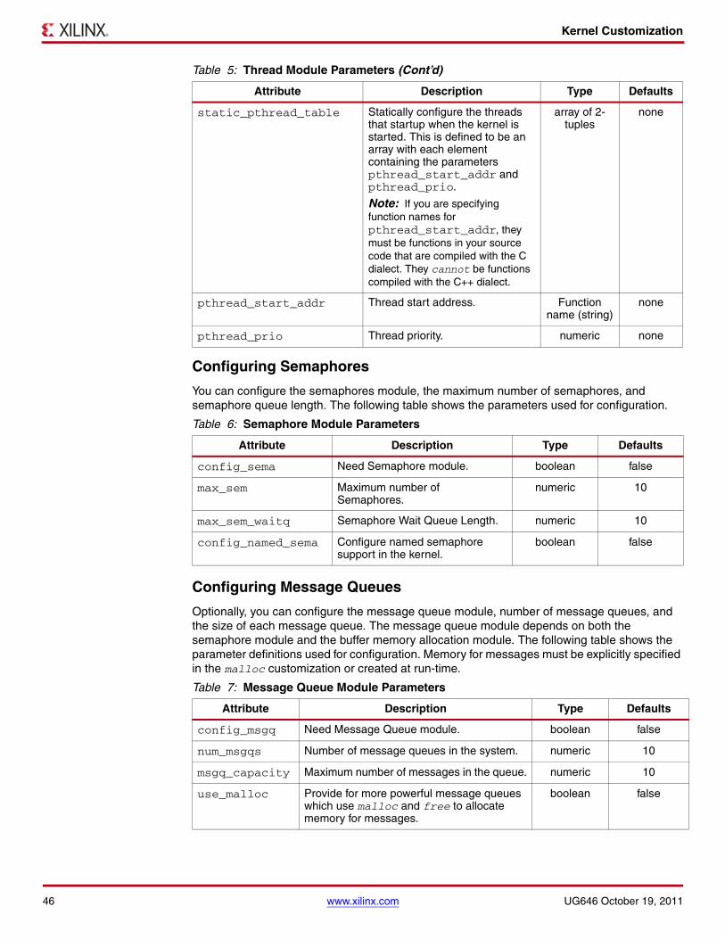
Kernel Customization
Configuring Semaphores
You can configure the semaphores module, the maximum number of semaphores, and semaphore queue length. The following table shows the parameters used for configuration.
Configuring Message Queues
Optionally, you can configure the message queue module, number of message queues, and the size of each message queue. The message queue module depends on both the semaphore module and the buffer memory allocation module. The following table shows the parameter definitions used for configuration. Memory for messages must be explicitly specified in the malloc customization or created at run-time.
static_pthread_table Statically configure the threads that startup when the kernel is started. This is defined to be an array with each element containing the parameters pthread_start_addr and pthread_prio.
Note: If you are specifying function names for pthread_start_addr, they must be functions in your source code that are compiled with the C dialect. They cannot be functions compiled with the C++ dialect.
array of 2-tuples
none
pthread_start_addr Thread start address. Function name (string)
none
pthread_prio Thread priority. numeric none
Table 6: Semaphore Module Parameters
Attribute Description Type Defaults
config_sema Need Semaphore module. boolean false
max_sem Maximum number of Semaphores.
numeric 10
max_sem_waitq Semaphore Wait Queue Length. numeric 10
config_named_sema Configure named semaphore support in the kernel.
boolean false
Table 7: Message Queue Module Parameters
Attribute Description Type Defaults
config_msgq Need Message Queue module. boolean false
num_msgqs Number of message queues in the system. numeric 10
msgq_capacity Maximum number of messages in the queue. numeric 10
use_malloc Provide for more powerful message queues which use malloc and free to allocate memory for messages.
boolean false
Table 5: Thread Module Parameters (Cont’d)
Attribute Description Type Defaults
46 www.xilinx.com UG646 October 19, 2011

Kernel Customization
Configuring Shared Memory
Optionally, you can configure the shared memory module and the size of each shared memory segment. All the shared memory segments that are needed must be specified in these parameters.The following table shows the parameters used for configuration.
Configuring Pthread Mutex Locks
Optionally, you can choose to include the pthread mutex module, number of mutex locks, and the size of the wait queue for the mutex locks. The following table shows the parameters used for configuration.
Configuring Buffer Memory Allocation
Optionally, you can configure the dynamic buffer memory management module, size of memory blocks, and number of memory blocks. The following table shows the parameters used for configuration.
Table 8: Shared Memory Module Parameters
Attribute Description Type Defaults
config_shm Need shared memory module. boolean false
shm_table Shared memory table. Defined as an array with each element having shm_size parameter.
array of 1-tuples none
shm_size Shared memory size. numeric none
num_shm Number of shared memories expressed as the shm_table array size.
numeric none
Table 9: Pthread Mutex Module Parameters
Attribute Description Type Defaults
config_pthread_mutex Need pthread mutex module. boolean false
max_pthread_mutex Maximum number of pthread mutex locks available in the system.
numeric 10
max_pthread_mutex_ waitq Length of each the mutex lock wait queue.
numeric 10
Table 10: Memory Management Module Parameters
Attribute Description Type Defaults
config_bufmalloc Need buffer memory management. boolean false
max_bufs Maximum number of buffer pools that can be managed at any time by the kernel.
numeric 10
mem_table Memory block table. This is defined as an array with each element having mem_bsize, mem_nblks parameters.
array of 2-tuples none
mem_bsize Memory block size in bytes. numeric none
mem_nblks Number of memory blocks of a size. numeric none
UG646 October 19, 2011 www.xilinx.com 47

Kernel Customization
Configuring Software Timers
Optionally, you can configure the software timers module and the maximum number of timers supported. The following table shows the parameters used for configuration.
Configuring Enhanced Interfaces
Optionally, you can configure some enhanced features/interfaces using the following parameters shown in the following table.
Configuring System Timer
You can configure the timer device in the system for MicroBlaze processor kernels. Additionally, you can configure the timer interval for PowerPC and PIT timer based MicroBlaze processor systems. The following table shows the available parameters .
Table 11: Software Timers Module Parameters
Attribute Description Type Defaults
config_time Need software timers and time management module.
boolean false
max_tmrs Maximum number of software timers in the kernel. numeric 10
Table 12: Enhanced Features
Attribute Description Type Defaults
config_kill Include the ability to kill a process with the kill( ) function.
boolean false
config_yield Include the yield( ) interface. boolean false
Table 13: Attributes for Copying Kernel Source Files
Attribute Description Type Defaults
systmr_dev1
1. MicroBlaze only.
Instance name of the system timer peripheral.
string none
systmr_freq Specify the clock frequency of the system timer device:• For the xps_timer, it is the OPB
clock frequency.• For the axi_timer, it is the
frequency of the AXI bus to which the axi_timer is connected.
• For the fit_timer, it is the clock given to the fit_timer.
• For PowerPC 405 processor, it is the frequency of the PowerPC 405.
numeric 100000000
systmr_interval Time interval per system timer interrupt. This is automatically determined (and cannot be changed) for the fit_timer.
numeric (milliseconds)
10
48 www.xilinx.com UG646 October 19, 2011
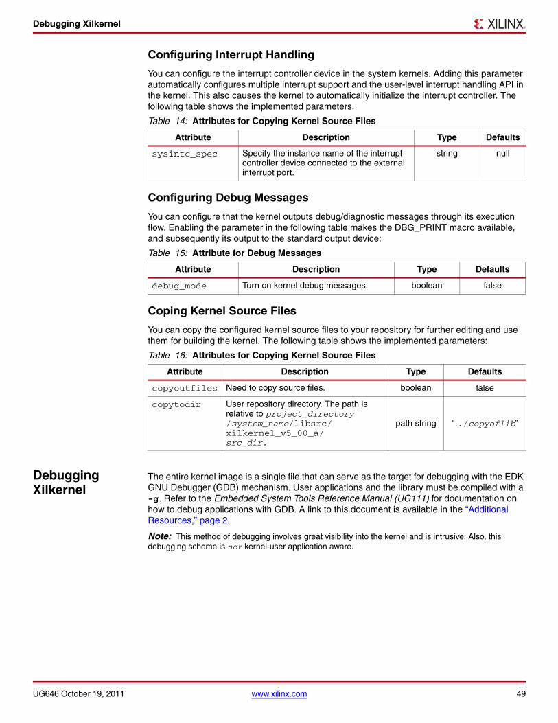
Debugging Xilkernel
Configuring Interrupt Handling
You can configure the interrupt controller device in the system kernels. Adding this parameter automatically configures multiple interrupt support and the user-level interrupt handling API in the kernel. This also causes the kernel to automatically initialize the interrupt controller. The following table shows the implemented parameters.
Configuring Debug Messages
You can configure that the kernel outputs debug/diagnostic messages through its execution flow. Enabling the parameter in the following table makes the DBG_PRINT macro available, and subsequently its output to the standard output device:
Coping Kernel Source Files
You can copy the configured kernel source files to your repository for further editing and use them for building the kernel. The following table shows the implemented parameters:
Debugging Xilkernel
The entire kernel image is a single file that can serve as the target for debugging with the EDK GNU Debugger (GDB) mechanism. User applications and the library must be compiled with a -g. Refer to the Embedded System Tools Reference Manual (UG111) for documentation on how to debug applications with GDB. A link to this document is available in the “Additional Resources,” page 2.
Note: This method of debugging involves great visibility into the kernel and is intrusive. Also, this debugging scheme is not kernel-user application aware.
Table 14: Attributes for Copying Kernel Source Files
Attribute Description Type Defaults
sysintc_spec Specify the instance name of the interrupt controller device connected to the external interrupt port.
string null
Table 15: Attribute for Debug Messages
Attribute Description Type Defaults
debug_mode Turn on kernel debug messages. boolean false
Table 16: Attributes for Copying Kernel Source Files
Attribute Description Type Defaults
copyoutfiles Need to copy source files. boolean false
copytodir User repository directory. The path is relative to project_directory/system_name/libsrc/xilkernel_v5_00_a/src_dir.
path string "../copyoflib”
UG646 October 19, 2011 www.xilinx.com 49
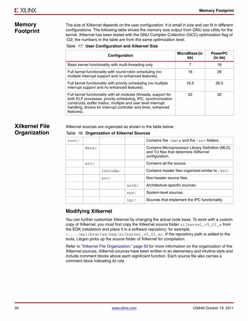
Memory Footprint
Memory Footprint
The size of Xilkernel depends on the user configuration. It is small in size and can fit in different configurations. The following table shows the memory size output from GNU size utility for the kernel. Xilkernel has been tested with the GNU Compiler Collection (GCC) optimization flag of -O2; the numbers in the table are from the same optimization level.
Xilkernel File Organization
Xilkernel sources are organized as shown in the table below:
Modifying Xilkernel
You can further customize Xilkernel by changing the actual code base. To work with a custom copy of Xilkernel, you must first copy the Xilkernel source folder xilkernel_v5_01_a from the EDK installation and place it in a software repository; for example, <..../mylibraries/bsp/xilkernel_v5_01_a>. If the repository path is added to the tools, Libgen picks up the source folder of Xilkernel for compilation.
Refer to “Xilkernel File Organization,” page 50 for more information on the organization of the Xilkernel sources. Xilkernel sources have been written in an elementary and intuitive style and include comment blocks above each significant function. Each source file also carries a comment block indicating its role.
Table 17: User Configuration and Xilkernel Size
Configuration MicroBlaze (in kb)
PowerPC (in kb)
Basic kernel functionality with multi-threading only. 7 16
Full kernel functionality with round-robin scheduling (no multiple interrupt support and no enhanced features).
16 26
Full kernel functionality with priority scheduling (no multiple interrupt support and no enhanced features).
16.5 26.5
Full kernel functionality with all modules (threads, support for both ELF processes, priority scheduling, IPC, synchronization constructs, buffer malloc, multiple and user level interrupt handling, drivers for interrupt controller and timer, enhanced features).
22 32
Table 18: Organization of Xilkernel Sources
root/ Contains the /data and the /src folders.
data/ Contains Microprocessor Library Definition (MLD) and Tcl files that determine XilKernel configuration.
src/ Contains all the source.
include/ Contains header files organized similar to /src.
src/ Non-header source files.
arch/ Architecture-specific sources.
sys/ System-level sources.
ipc/ Sources that implement the IPC functionality.
50 www.xilinx.com UG646 October 19, 2011

Deprecated Features
Deprecated Features
ELF Process Management (Deprecated)
A deprecated feature of Xilkernel is the support for creating execution contexts out of separate Executable Linked Files (ELFs).
You might do this if you need to create processes out of executable files that lay on a file system (such as XilFATFS or XilMFS). Typically, a loader is required, which Xilkernel does not provide. Assuming that your application does involve a loader, then given a entry point in memory to the executable, Xilkernel can then create a process. The kernel does not allocate a separate stack for such processes; the stack is set up as a part of the CRT of the separate executable.
Note: Such separate executable ELF files, which are designed to run on top of Xilkernel, must be compiled with the compiler flag -xl-mode-xilkernel for MicroBlaze processors. For PowerPC processors, you must use a custom linker script, that does not include the .boot and the .vectors sections in the final ELF image. The reason that these modifications are required is that, by default, any program compiled with the EDK GNU tool flow, could potentially contain sections that overwrite the critical interrupt, exception, and reset vectors section in memory. Xilkernel requires that its own ELF image initialize these sections and that they stay intact. Using these special compile flags and linker scripts, removes these sections from the output image for applications.
The separate executable mode has the following caveats:
• Global pointer optimization is not supported.
Note: This is supported in the default kernel linkage mode. It is not supported only in this separate executable mode.
• Xilkernel does not feature a loader when creating new processes and threads. It creates process and thread contexts to start of from memory images assumed to be initialized. Therefore, if any ELF file depends on initialized data sections, then the next time the same memory image is used to create a process, the initialized sections are invalid, unless some external mechanism is used to reload the ELF image before creating the process.
Note: This feature is deprecated. Xilinx encourages use of the standard, single executable file application model.
Refer to the “Configuring ELF Process Management (Deprecated),” page 52 for more details. An ELF process is created and handled using the following interfaces.
int elf_process_create(void* start_addr, int prio)Parameters start_addr is the start address of the process.
prio is the starting priority of the process in the system.
Returns • The PID of the new process on success.• -1 on failure.
Description Creates a new process. Allocates a new PID and Process Control Block (PCB) for the process.The process is placed in the appropriate ready queue.
Includes xmk.h, sys/process.h
UG646 October 19, 2011 www.xilinx.com 51

Deprecated Features
int elf_process_exit(void)
Configuring ELF Process Management (Deprecated)
You can select the maximum number of processes in the system and the different functions needed to handle processes. The processes and threads that are present in the system on system startup can be configured statically. The following table provides a list of available parameters:
Parameters None.
Returns None.
Description Removes the process from the system.
Caution! Do not use this function to terminate a thread.
Includes xmk.h, sys/process.h
Table 19: Process Management Parameters
Attribute Description Type Defaults
config_elf_process Need ELF process management.
Note: Using config_elf_process requires enhanced_features=true in the kernel configuration.
boolean true
max_procs Maximum number of processes in the system. numeric 10
static_elf_process_table
Configure startup processes that are separate executable files. This is defined to be an array with each element containing the parameters process_start and process_prio.
Array of 2-tuples
none
process_start_addr Process start address. Address none
process_prio Process priority. Numeric none
52 www.xilinx.com UG646 October 19, 2011

Overview The XilFATFS filesystem access library provides read/write access to files stored on a Xilinx® System ACE compact flash or IBM microdrive device. This library requires the underlying hardware platform to contain the following:
• XPS/AXI System ACE Interface Controller - Logicore module
• System ACE controller and CompactFlash connector
• CompactFlash card or IBM Microdrive formatted with a FAT12, FAT16, or FAT32 file system
Caution! FAT16 is required for the System ACE to directly configure the FPGA but the XilFATFS library can work with the System ACE hardware to support FAT12 and FAT32 also.
You can copy files to the flash device from your PC by plugging the flash or microdrive into a suitable USB adapter or similar device.
If the compact flash or microdrive has multiple partitions, each formatted as a FAT12, FAT16, or FAT32 filesystem, XilFATFS allows the partitions to be accessed with partition names. The first partition is always called A:, the second partition is always called B:, and so on. As noted earlier, the first partition must be FAT16 for the System ACE to directly configure the FPGA.
The following sections provide a summary of the XilFATFS functions and the function descriptions.
XilFATFS Function Summary
This section provides a list of functions provided by the XilFATFS. The following is a linked list where you can click on the function name to go to the description.
UG648 July 6, 2011
LibXil FATFile System (FATFS) (v1.00.a)
void *sysace_fopen(const char *file, const char *mode) int sysace_fread (void *buffer, int_size, int count, void *file) int sysace_fwrite(void *buffer, int size, int count, void *file) int sysace_fclose(void *file) int sysace_mkdir(const char *path) int sysace_chdir(const char *path) int sysace_remove_dir(const char *path) int sysace_remove_file(const char *path)
UG648 July 6, 2011 www.xilinx.com 1
© 2011 Xilinx, Inc. XILINX, the Xilinx logo, Virtex, Spartan, ISE, and other designated brands included herein are trademarks of Xilinx in the United States and other countries. All other trademarks are the property of their respective owners.

XilFATFS Function Descriptions
XilFATFS Function Descriptions
void *sysace_fopen(const char *file, const char *mode)
int sysace_fread (void *buffer, int_size, int count, void *file)
int sysace_fwrite(void *buffer, int size, int count, void *file)
Parameters file is the name of the file on the flash device.mode is “r” or “w”.
Returns A non-zero file handle on success.0 for failure.
Description The file name must follow the Microsoft 8.3 naming convention of an eight character file name followed by a ‘.’ and a three character extension. For example: test.txt.This function returns a file handle that has to be used for subsequent calls to read, write, or close the file.If mode is “r” and the named file does not exist on the device, a 0 is returned.
Includes sysace_stdio.h
Parameters buffer is a pre allocated buffer that is passed in to this procedure, and is used to return the characters read from the device.size is restricted to 1.count is the number of characters to be read.file is the file handle returned by sysace_fopen.
Returns Non-zero number of characters actually read for success.0 for failure.
Description The preallocated buffer is filled with the characters that are read from the device. The return value indicates the actual number of characters read, while count specifies the maximum number of characters to read. The buffer size must be at least count. stream should be a valid file handle returned by a call to sysace_fopen.
Includes sysace_stdio.h
Parameters buffer is a pre allocated buffer that is passed in to this procedure, and contains the characters to be written to the device.size is restricted to 1.count is the number of characters to be written.file is the file handle returned by sysace_fopen.
Returns Non-zero number of characters actually written for success.0 or -1 for failure.
Description The pre-allocated buffer is filled (by the caller) with the characters that are to be written to the device. The return value indicates the actual number of characters written, while count specifies the maximum number of characters to write. The buffer size must be at least count. stream should be a valid file handle returned by a call to sysace_fopen. This function might simply return after updating the buffer cache (see CONFIG_BUFCACHE_SIZE). To ensure that the data is written to the device, perform a sysace_fclose call.
Includes sysace_stdio.h
2 www.xilinx.com UG648 July 6, 2011

XilFATFS Function Descriptions
int sysace_fclose(void *file)
int sysace_mkdir(const char *path)
int sysace_chdir(const char *path)
Parameters file: File handle returned by sysace_fopen.
Returns 0 on success.-1 on failure.
Description Closes an open file. This function also synchronizes the buffer cache to memory. If any files were written to using sysace_fwrite, then it is necessary to synchronize the data to the disk by performing sysace_fclose. If this is not performed, then the disk could possibly become corrupted.
Includes sysace_stdio.h
Parameters path is the path name of new directory.
Returns 0 on success.-1 on failure.
Description Create a new directory specified by path. The directory name can be either absolute or relative, and must follow the 8.3 file naming convention.Examples: a:\\dirname, a:\\dirname.dir, a:\\dir1\\dirnew, dirname, dirname.dir
If a relative path is specified, and the current working directory is not already set, the current working directory defaults to the root directory.
Includes sysace_stdio.h
Parameters path is the path name of new directory
Returns 0 on success-1 on failure
Description Create a new directory specified by path. The directory name can be either absolute or relative, and must follow the 8.3 file naming convention.Examples: a:\\dirname, a:\\dirname.dir, a:\\dir1\\dirnew, dirname, dirname.dir
If a relative path is specified, and the current working directory is not already set, the current working directory defaults to the root directory.
Includes sysace_stdio.h
UG648 July 6, 2011 www.xilinx.com 3

Libgen Customization
int sysace_remove_dir(const char *path)
int sysace_remove_file(const char *path)
Libgen Customization
XilFATFS file system can be integrated with a system using the following snippet in the Microprocessor Software Specification (MSS) file:
BEGIN LIBRARYparameter LIBRARY_NAME = xilfatfsparameter LIBRARY_VER = 1.00.aparameter CONFIG_WRITE = trueparameter CONFIG_DIR_SUPPORT = falseparameter CONFIG_FAT12 = falseparameter CONFIG_MAXFILES = 5parameter CONFIG_BUFCACHE_SIZE = 10240parameter PROC_INSTANCE = powerpc_0
END LIBRARY
Parameter description:
• When CONFIG_WRITE is set to true, write capabilities are added to the library.
• When CONFIG_DIR_SUPPORT is set to true, the mkdir and chdir functions are added to the library. For mkdir() function to work, CONFIG_WRITE needs to be enabled.
• When CONFIG_FAT12 is set to true, the library is configured to work with FAT12 file systems. Otherwise, the library works with both FAT16 and FAT32 file systems.
• CONFIG_MAXFILES limits the maximum number of files that can be open. This influences the amount of memory allocated statically by XilFATFS.
• CONFIG_BUFCACHE_SIZE: defines the amount of memory (in bytes) used by the library for buffering reads and write calls to the System ACE. This improves the performance of both sysace_fread and sysace_fwrite by buffering the data in memory and avoiding unnecessary calls to read the CF device. The buffers are synced up to the device only on a sysace_fclose call; consequently, it is essential to perform a sysace_fclose if any file was modified.
• The parameter PROC_INST is not necessary for uniprocessor systems. In a multiprocessor system, set PROC_INST to the processor name for which the library must be compiled. The System ACE peripheral must be reachable from this processor.
Parameters path is the full path to the directory that must be deleted.
Returns 0 on successNegative integer on failure.
Description Remove the file or directory specified by the path. Available only when the CONFIG_WRITE parameter to XilFATFS is set.
Includes sysace_stdio.h
Parameters path is the full path to the file that must be deleted.
Returns 0 on success.Negative integer on failure.
Description Remove the file or directory specified by the path. These functions are available only when the CONFIG_WRITE parameter to XilFATFS is set.
Includes sysace_stdio.h
4 www.xilinx.com UG648 July 6, 2011

Overview The LibXil MFS provides the capability to manage program memory in the form of file handles. You can create directories and have files within each directory. The file system can be accessed from the high-level C language through function calls specific to the file system.
MFS Functions This section provides a linked summary and descriptions of MFS functions.
MFS Function Summary
The following list is a linked summary of the supported MFS functions. Descriptions of the functions are provided after the summary table. You can click on a function in the summary list to go to the description.
UG649 July 6, 2011
LibXil Memory File System (MFS) (v1.00.a)
void mfs_init_fs(int_numbytes,_char_*address,_int init_type) void mfs_init_genimage(int numbytes, char *address, int init_type) int mfs_change_dir(char_*newdir) int mfs_create_dir(char *newdir) int mfs_delete_dir(char *dirname) 3int mfs_get_current_dir_name(char *dirname) int mfs_delete_file(char *filename) 3int mfs_rename_file(char *from_file, char *to_file) int mfs_exists_file(char *filename) int mfs_get_usage(int *num_blocks_used, int *num_blocks_free) int mfs_dir_open(char *dirname) int mfs_dir_close(int fd) int mfs_dir_read(int fd, char_**filename, int *filesize,int *filetype) int mfs_file_open(char *filename, int mode) int mfs_file_read(int fd, char *buf, int buflen) int mfs_file_write(int fd, char *buf, int buflen) int mfs_file_close(int fd) long mfs_file_lseek(int fd, long offset, int whence)
UG649 July 6, 2011 www.xilinx.com 1
© 2011 Xilinx, Inc. XILINX, the Xilinx logo, Virtex, Spartan, ISE, and other designated brands included herein are trademarks of Xilinx in the United States and other countries. All other trademarks are the property of their respective owners.

MFS Functions
MFS Function Descriptions
void mfs_init_fs(int_numbytes,_char_*address,_int init_type)
void mfs_init_genimage(int numbytes, char *address, int init_type)
int mfs_change_dir(char_*newdir)
Parameters numbytes is the number of bytes of memory available for the file system.address is the starting(base) address of the file system memory.init_type is MFSINIT_NEW, MFSINIT_IMAGE, or MFSINIT_ROM_IMAGE.
Description Initialize the memory file system. This function must be called before any file system operation. Use mfs_init_genimage instead of this function if the filesystem is being initialized with an image generated by mfsgen. The status/mode parameter determines certain filesystem properties:• MFSINIT_NEW creates a new, empty file system for read/write.• MFSINIT_IMAGE initializes a filesystem whose data has been previously
loaded into memory at the base address.• MFSINIT_ROM_IMAGE initializes a Read-Only filesystem whose data has
been previously loaded into memory at the base address.
Includes xilmfs.h
Parameters numbytes is the number of bytes of memory in the image generated by the mfsgen tool. This is equal to the size of the memory available for the file system, plus 4.address is the starting(base) address of the image.init_type is either MFSINIT_IMAGE or MFSINIT_ROM_IMAGE
Description Initialize the memory file system with an image generated by mfsgen. This function must be called before any file system operation. The status/mode parameter determines certain filesystem properties:• MFSINIT_IMAGE initializes a filesystem whose data has been
previously loaded into memory at the base address.• MFSINIT_ROM_IMAGE initializes a Read-Only filesystem whose
data has been previously loaded into memory at the base address.
Includes xilmfs.h
Parameters newdir is the chdir destination.
Returns 1 on success.0 on failure.
Description If newdir exists, make it the current directory of MFS. Current directory is not modified in case of failure.
Includes xilmfs.h
2 www.xilinx.com UG649 July 6, 2011

MFS Functions
int mfs_create_dir(char *newdir)
int mfs_delete_dir(char *dirname)
int mfs_get_current_dir_name(char *dirname)
int mfs_delete_file(char *filename)
Parameters newdir is the directory name to be created.
Returns Index of new directory in the file system on success.0 on failure.
Description Create a new empty directory called newdir inside the current directory.
Includes xilmfs.h
Parameters dirname is the directory to be deleted.
Returns Index of new directory in the file system on success.0 on failure.
Description Delete the directory dirname, if it exists and is empty.
Includes xilmfs.h
Parameters dirname is the current directory name.
Returns 1 on success.0 on failure.
Description Return the name of the current directory in a preallocated buffer, dirname, of at least 16 chars. It does not return the absolute path name of the current directory, but just the name of the current directory.
Includes xilmfs.h
Parameters filename is the file to be deleted.
Returns 1 on success.0 on failure.
Description Delete filename from the directory.
Includes xilmfs.h
Caution! This function does not completely free up the directory space used by the file. Repeated calls to create and delete files can cause the filesystem to run out of space.
UG649 July 6, 2011 www.xilinx.com 3

MFS Functions
int mfs_rename_file(char *from_file, char *to_file)
int mfs_exists_file(char *filename)
int mfs_get_usage(int *num_blocks_used, int*num_blocks_free)
int mfs_dir_open(char *dirname)
Parameters from_file is the original filename.to_file is the new file name.
Returns 1 on success.0 on failure.
Description Rename from_file to to_file. Rename works for directories as well as files. Function fails if to_file already exists.
Includes xilmfs.h
Parameters filename is the file or directory to be checked for existence.
Returns 0 if filename does not exist.1 if filename is a file.2 if filename is a directory.
Description Check if the file/directory is present in current directory.
Includes xilmfs.h
Parameters num_blocks_used is the number of blocks used.num_blocks_free is the number of free blocks.
Returns 1 on success.0 on failure.
Description Get the number of used blocks and the number of free blocks in the file system through pointers.
Includes xilmfs.h
Parameters dirname is the directory to be opened for reading.
Returns The index of dirname in the array of open files on success.-1 on failure.
Description Open directory dirname for reading. Reading a directory is done using mfs_dir_read( ).
Includes xilmfs.h
4 www.xilinx.com UG649 July 6, 2011

MFS Functions
int mfs_dir_close(int fd)
int mfs_dir_read(int fd, char_**filename, int *filesize,int *filetype)
int mfs_file_open(char *filename, int mode)
Parameters fd is file descriptor return by open.
Returns 1 on success.0 on failure.
Description Close the dir pointed by fd. The file system regains the fd and uses it for new files.
Includes xilmfs.h
Parameters fd is the file descriptor return by open; passed to this function by caller.filename is the pointer to file name at the current position in the directory in MFS; this value is filled in by this function.filesize is the pointer to a value filled in by this function: Size in bytes of filename, if it is a regular file; Number of directory entries if filename is a directory.filetype is the pointer to a value filled in by this function: MFS_BLOCK_TYPE_FILE if filename is a regular file. MFS_BLOCK_TYPE_DIR if filename is a directory.
Returns 1 on success.0 on failure.
Description Read the current directory entry and advance the internal pointer to the next directory entry. filename, filetype, and filesize are pointers to values stored in the current directory entry.
Includes xilmfs.h
Parameters filename is the file to be opened.mode is Read/Write or Create.
Returns The index of filename in the array of open files on success.-1 on failure.
Description Open file filename with given mode. The function should be used for files and not directories:• MODE_READ, no error checking is done (if file or directory).• MODE_CREATE creates a file and not a directory. • MODE_WRITE fails if the specified file is a DIR.
Includes xilmfs.h
UG649 July 6, 2011 www.xilinx.com 5

MFS Functions
int mfs_file_read(int fd, char *buf, int buflen)
int mfs_file_write(int fd, char *buf, int buflen)
int mfs_file_close(int fd)
Parameters fd is the file descriptor return by open.buf is the destination buffer for the read.buflen is the length of the buffer.
Returns Number of bytes read on success.0 on failure.
Description Read buflen number bytes and place it in buf.fd should be a valid index in “open files” array, pointing to a file, not a directory. buf should be a pre-allocated buffer of size buflen or more. If fewer than buflen chars are available then only that many chars are read.
Includes xilmfs.h
Parameters fd is the file descriptor return by open.buf is the source buffer from where data is read.buflen is the length of the buffer.
Returns 1 on success.0 on failure.
Description Write buflen number of bytes from buf to the file. fd should be a valid index in open_files array. buf should be a pre-allocated buffer of size buflen or more.
Caution! Writing to locations other than the end of the file is not supported.Using mfs_file_lseek( ) go to some other location in the file then calling mfs_file_write( ) is not supported
Includes xilmfs.h
Parameters fd is the file descriptor return by open.
Returns 1 on success.0 on failure.
Description Close the file pointed by fd. The file system regains the fd and uses it for new files.
Includes xilmfs.h
6 www.xilinx.com UG649 July 6, 2011

Utility Functions
long mfs_file_lseek(int fd, long offset, int whence)
Utility Functions
The following subsections provide a summary and the descriptions of the utility functions that can be used along with the MFS. These functions are defined in mfs_filesys_util.c and are declared in xilmfs.h.
Utility Function Summary
The following list is a linked summary of the supported MFS Utility functions. Descriptions of the functions are provided after the summary table. You can click on a function in the summary list to go to the description.
Parameters fd is the file descriptor return by open.offset is the number of bytes to seek.whence is the file system dependent mode:• MFS_SEEK_END, then offset can be either 0 or negative, otherwise
offset is non-negative. • MFS_SEEK_CURR, then offset is calculated from the current location.• MFS_SEEK_SET, then offset is calculated from the start of the file.
Returns Returns offset from the beginning of the file to the current location on success.-1 on failure: the current location is not modified.
Description Seek to a given offset within the file at location fd in open_files array.
Caution! It is an error to seek before beginning of file or after the end of file.
Caution! Writing to locations other than the end of the file is not supported. Using the mfs_file_lseek( ) function or going to some other location in the file then calling mfs_file_write( ) is not supported.
Includes xilmfs.h
int mfs_ls(void) int mfs_ls_r(int recurse) int mfs_cat(char* filename) int mfs_copy_stdin_to_file(char *filename) int mfs_file_copy(char *from_file, char *to_file)
UG649 July 6, 2011 www.xilinx.com 7

Utility Functions
Utility Function Descriptions
int mfs_ls(void)
int mfs_ls_r(int recurse)
int mfs_cat(char* filename)
int mfs_copy_stdin_to_file(char *filename)
Parameters None.
Returns 1 on success.0 on failure.
Description List contents of current directory on STDOUT.
Includes xilmfs.h
Parameters recurse controls the amount of recursion:• 0 lists the contents of the current directory and stop.• > 0 lists the contents of the current directory and any subdirectories up to a
depth of recurse.• = -1 completes recursive directory listing with no limit on recursion depth.
Returns 1 on success.0 on failure.
Description List contents of current directory on STDOUT.
Includes xilmfs.h
Parameters filename is the file to be displayed.
Returns 1 on success.0 on failure.
Description Print the file to STDOUT.
Includes xilmfs.h
Parameters filename is the destination file.
Returns 1 on success.0 on failure.
Description Copy from STDIN to named file. An end-of-file (EOF) character should be sent from STDIN to allow the function to return 1.
Includes xilmfs.h
8 www.xilinx.com UG649 July 6, 2011

Additional Utilities
int mfs_file_copy(char *from_file, char *to_file)
Additional Utilities
The mfsgen program is provided along with the MFS library. You can use mfsgen to create an MFS memory image on a host system that can be subsequently downloaded to the embedded system memory. The mfsgen links to LibXil MFS and is compiled to run on the host machine rather than the target MicroBlaze™ or PowerPC® processor system. Conceptually, this is similar to the familiar zip or tar programs.
An entire directory hierarchy on the host system can be copied to a local MFS file image using mfsgen. This file image can then be downloaded on to the memory of the embedded system for creating a pre-loaded file system.
Test programs are included to illustrate this process. For more information, see the readme.txt file in the utils sub-directory.
Usage: mfsgen -{c filelist| t | x} vsb num_blocks f mfs_filename
Specify exactly one of c, t, or x modes
c: creates an mfs file system image using the list of files specified on the command line (directories specified in this list are traversed recursively).
t: lists the files in the mfs file system image
x: extracts the mfs file system from image to host file system
v: is verbose mode
s: switches endianness
b: lists the number of blocks (num_blocks) which should be more than 2
- If the b option is specified, the num_blocks value should be specified
- If the b option is omitted, the default value of num_blocks is 5000
- The b option is meaningful only when used in conjunction with the c option
f: specify the host file name (mfs_filename) where the mfs file system image is stored
- If the f option is specified, the mfs filename should be specified
- If the f option is omitted, the default file name is filesystem.mfs
Parameters from_file is the source file.to_file is the destination file.
Returns 1 on success.0 on failure.
Description Copy from_file to to_file. Copy fails if to_file already exists or either from or to location cannot be opened.
Includes xilmfs.h
UG649 July 6, 2011 www.xilinx.com 9
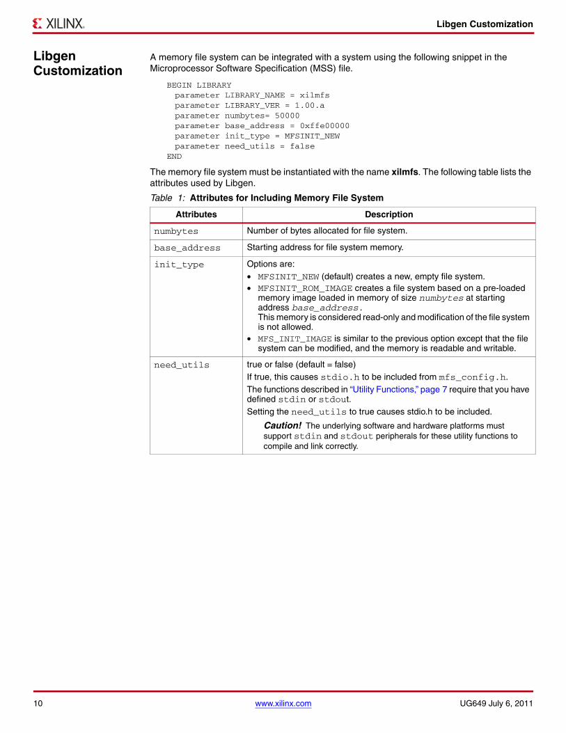
Libgen Customization
Libgen Customization
A memory file system can be integrated with a system using the following snippet in the Microprocessor Software Specification (MSS) file.
BEGIN LIBRARYparameter LIBRARY_NAME = xilmfsparameter LIBRARY_VER = 1.00.aparameter numbytes= 50000parameter base_address = 0xffe00000parameter init_type = MFSINIT_NEWparameter need_utils = false
END
The memory file system must be instantiated with the name xilmfs. The following table lists the attributes used by Libgen.
Table 1: Attributes for Including Memory File System
Attributes Description
numbytes Number of bytes allocated for file system.
base_address Starting address for file system memory.
init_type Options are:• MFSINIT_NEW (default) creates a new, empty file system.• MFSINIT_ROM_IMAGE creates a file system based on a pre-loaded
memory image loaded in memory of size numbytes at starting address base_address. This memory is considered read-only and modification of the file system is not allowed.
• MFS_INIT_IMAGE is similar to the previous option except that the file system can be modified, and the memory is readable and writable.
need_utils true or false (default = false)If true, this causes stdio.h to be included from mfs_config.h.The functions described in “Utility Functions,” page 7 require that you have defined stdin or stdout. Setting the need_utils to true causes stdio.h to be included.
Caution! The underlying software and hardware platforms must support stdin and stdout peripherals for these utility functions to compile and link correctly.
10 www.xilinx.com UG649 July 6, 2011

l
Overview The lwIP is an open source TCP/IP protocol suite available under the BSD license. The lwIP is a standalone stack; there are no operating systems dependencies, although it can be used along with operating systems. The lwIP provides two APIs for use by applications:
• RAW API: Provides access to the core lwIP stack.
• Socket API: Provides a BSD sockets style interface to the stack.
The lwip140_v1_02_a is an EDK library that is built on the open source lwIP library version 1.4.0. The lwip140_v1_02_a library provides adapters for the Ethernetlite (xps_ethernetlite, axi_ethernetlite), the TEMAC (xps_ll_temac, axi_ethernet), and the Gigabit Ethernet MAC (GEM) cores. The library can run on MicroBlaze™, PowerPC® 405, PowerPC 440, and ARM Cortex-A9 processors. The Ethernetlite and TEMAC cores apply for MicroBlaze and PowerPC systems. The Gigabit Ethernet MAC (GEM) core is applicable only for ARM Cortex-A9 system (Zynq™ devices).
Features The lwIP provides support for the following protocols:
• Internet Protocol (IP)
• Internet Control Message Protocol (ICMP)
• User Datagram Protocol (UDP)
• TCP (Transmission Control Protocol (TCP)
• Address Resolution Protocol (ARP)
• Dynamic Host Configuration Protocol (DHCP)
• Internet Group Message Protocol (IGMP)
Additional Resources
• lwIP wiki: http://lwip.scribblewiki.com
• Xilinx® lwIP designs and application examples: http://www.xilinx.com/support/documentation/application_notes/xapp1026.pdf
• lwIP examples using RAW and Socket APIs: http://savannah.nongnu.org/projects/lwip/
UG650 July 25, 2012
lwIP 1.4.0 Library (v1.02.a)
UG650 July 25, 2012 www.xilinx.com 1
© 2012 Xilinx, Inc. XILINX, the Xilinx logo, Virtex, Spartan, ISE, and other designated brands included herein are trademarks of Xilinx in the United States and other countries. All other trademarks are the property of their respective owners.

Using lwIP
Using lwIP The following sections detail the hardware and software steps for using lwIP for networking in an EDK system. The key steps are:
1. Creating a hardware system containing the processor, ethernet core, and a timer. The timer and ethernet interrupts must be connected to the processor using an interrupt controller.
2. Configuring lwip140_v1_02_a to be a part of the software platform. For lwip socket API, the Xilkernel library is a pre-requisite.
Note: The Xilkernel library is available only for MicroBlaze and PowerPC systems. For ARM Cortex-A9 (Zynq), there is no support for the Xilkernel library. Therefore, the lwip socket API cannot be run on ARM Cortex-A9 systems (Zynq). Any subsequent discussion regarding socket API does not apply to Zynq systems.
Setting up the Hardware System
This section describes the hardware configurations supported by lwIP. The key components of the hardware system include:
• Processor: Either a PowerPC (405 or 440), a MicroBlaze, or a Cortex-A9 processor. The Cortex-A9 system applies to Zynq systems.
• MAC: LwIP supports xps_ethernetlite, axi_ethernetlite, xps_ll_temac, axi_ethernet, and gigabit ethernet MAC (GEM) cores.
• Timer: to maintain TCP timers, lwIP requires that certain functions are called at periodic intervals by the application. An application can do this by registering an interrupt handler with a timer.
• DMA: The xps_ll_temac and the axi_ethernet cores can be configured with an optional soft Direct Memory Access (DMA) engine. For GEM in Zynq there is a built-in DMA and therefore no extra configuration is required.
The following figure shows a system architecture in which the system is using an xps_ethernetlite core.
The system has a processor connected to a Multi-Port Memory Controller (MPMC) with the other required peripherals (timer and ethernetlite) on the PLB v4.6 bus. Interrupts from both the timer and the ethernetlite are required, so interrupts are connected to the interrupt controller.
Figure 1 illustrates a system architecture using the xps_ethernetlite core.X-Ref Target - Figure 1
Figure 1: System Architecture using xps_ethernetlite Core
CPU:MicroBlaze or
PowerPCxps_intc
IRQ
MPMC xps_ethernetlite
PLBv46
Timer Interrupt
EMAC Interrupt
xps_timer
X11003
2 www.xilinx.com UG650 July 25, 2012

Setting up the Hardware System
When using TEMAC, the system architecture changes depending on whether DMA is required. If DMA is required, a fourth port (of type SDMA), which provides direct connection between the TEMAC (xps_ll_temac) and the memory controller (MPMC), is added to the memory controller. Figure 2 shows this system architecture.X-Ref Target - Figure 2
Note: There are four interrupts that are necessary in this case: a timer interrupt, a TEMAC interrupt, and the SDMA RX and TX interrupts. The SDMA interrupts are from the Multi-Port Memory Controller (MPMC) SDMA Personality Interface Module (PIM). Refer to the Multi-Port Memory Controller (MPMC) Data Sheet (DS643) for more information.
If the TEMAC is used without DMA, a FIFO (xps_ll_fifo) is used to interface to the TEMAC. The system architecture in this case is shown in Figure 3.X-Ref Target - Figure 3
Figure 2: System Architecture using xps_ll_temac Core (with DMA)
Figure 3: System Architecture using TEMAC with xps_II_fifo (without DMA)
CPU:MicroBlaze or
PowerPCxps_intc
IRQ
PLBv46
TEMAC Interrupt
SDMA Rx and
Tx Interrupt
Timer Interrupt
X11004
xps_ll_temac xps_timer MPMC
S D M A
CPU:MicroBlaze or
PowerPCxps_intc
IRQ
PLBv46
TEMAC Interrupt
Fifo Interrupt
Timer Interrupt
X11002
xps_timer xps_ll_fifo xps_ll_temac MPMC
UG650 July 25, 2012 www.xilinx.com 3

Setting up the Software System
Figure 4 shows a sample system architecture with a Spartan®-6 device utilizing the axi_ethernet core with DMA.
Setting up the Software System
To use lwip in a software application, you must first compile the lwip library as part of software application.
To move the hardware design to SDK, you must first export it from XPS.
1. Select Project > Export Hardware Design to SDK.
2. On the Export to SDK dialog box that opens, click Export & Launch SDK.
XPS exports the design to SDK. SDK opens and prompts you to create a workspace.
After SDK opens with hw_platform already present in the Project Explorer, compile the lwip library:
1. Select File > New > Xilinx Board Support Package.
The New Board Support Package window opens.
2. Give the project a name and select a location for it. Select XilKernel or Standalone, and click Finish.
Note: For Zynq there is no option for XilKernel.
The Board Support Package Settings window opens.
3. Select the lwip140 library with version 1.00.a.
On the left side of the SDK window, lwip140 appears in the list of libraries to be compiled.
4. Select lwip140 in the Project Explorer tab. The configuration options for lwip are listed. Configure the lwip and click OK.
The board support package automatically builds with lwip included in it.
X-Ref Target - Figure 4
Figure 4: System Architecture using axi_ethernet core with DMA
4 www.xilinx.com UG650 July 25, 2012

Setting up the Software System
Configuring lwIP Options
The lwIP provides configurable parameters. The values for these parameters can be changed in SDK. There are two major categories of configurable options:
• Xilinx Adapter to lwIP options: These control the settings used by Xilinx adapters for the ethernet cores.
• Base lwIP options: These options are part of lwIP library itself, and include parameters for TCP, UDP, IP and other protocols supported by lwIP.
The following sections describe the available lwIP configurable options.
Customizing lwIP API Mode
The lwip140_v1_02_a supports both raw API and socket API:
• The raw API is customized for high performance and lower memory overhead. The limitation of raw API is that it is callback-based, and consequently does not provide portability to other TCP stacks.
• The socket API provides a BSD socket-style interface and is very portable; however, this mode is inefficient both in performance and memory requirements.
The lwip140_v1_02_a also provides the ability to set the priority on TCP/IP and other lwIP application threads. Table 1 provides lwIP library API modes.
Configuring Xilinx Adapter Options
The Xilinx adapters for EMAC/GEM cores are configurable.
Ethernetlite Adapter Options
Table 2 provides the configuration parameters for the xps_ethernetlite adapter.
Table 1: API Mode Options and Descriptions
Attribute/Options Description Type Default
api_mode {RAW_API | SOCKET_API}
The lwIP library mode of operation. For Zynq systems there is no support for SOCKET_API.
enum RAW_API
socket_mode_thread_prio integer
Priority of lwIP TCP/IP thread and all lwIP application threads.This setting applies only when Xilkernel is used in priority mode.It is recommended that all threads using lwIP run at the same priority level.This is not applicable for GEM core in Zynq.
integer 1
Table 2: xps_ethernetlite Adapter Options
Attribute Description Type Default
sw_rx_fifo_size Software Buffer Size in bytes of the receive data between EMAC and processor
integer 8192
sw_tx_fifo_size Software Buffer Size in bytes of the transmit data between processor and EMAC
integer 8192
UG650 July 25, 2012 www.xilinx.com 5

Setting up the Software System
TEMAC Adapter Options
Table 3 provides the configuration parameters for the xps_ll_temac, axi_ethernet and GEM adapters.
Table 3: xps_ll_temac/axi-ethernet/GEM Adapter
Attribute Default Type Description
n_tx_descriptors 64 integer Number of Tx descriptors to be used
n_rx_descriptors 64 integer Number of Rx descriptors to be used
n_tx_coalesce 1 integer Setting for Tx interrupt coalescing1
1. This setting is not applicable for GEM in Zynq.
n_rx_coalesce 1 integer Setting for Rx interrupt coalescing1
tcp_rx_checksum_offload
false boolean Offload TCP Receive checksum calculation (hardware support required). For GEM in Zynq, the TCP receive checksum offloading is always present, so this attribute does not apply.
tcp_tx_checksum_offload
false boolean Offload TCP Transmit checksum calculation (hardware support required). For GEM cores (for Zynq) the TCP transmit checksum offloading is always present, so this attribute does not apply.
tcp_ip_rx_checksum_offload
false boolean Offload TCP and IP Receive checksum calculation (hardware support required).Applicable only for AXI systems. For GEM in Zynq the TCP and IP receive checksum offloading is always present, so this attribute does not apply.
tcp_ip_tx_checksum_offload
false boolean Offload TCP and IP Transmit checksum calculation (hardware support required).Applicable only for AXI systems. For GEM in Zynq the TCP and IP transmit checksum offloading is always present, so this attribute does not apply.
phy_link_speed enum CONFIG_LINKSPEED_AUTODETECT
Link speed as auto-negotiated by the PHY. lwIP configures the TEMAC/GEM for this speed setting. This setting must be correct for the TEMAC/GEM to transmit or receive packets.
Note: The CONFIG_LINKSPEED_AUTODETECT setting attempts to detect the correct linkspeed by reading the PHY registers; however, this is PHY dependent, and has been tested with the Marvell PHYs present on Xilinx development boards. For other PHYs, select the correct speed.
temac_use_jumbo_frames_experimental
false boolean Use TEMAC jumbo frames (with a size up to 9k bytes). If this option is selected, jumbo frames are allowed to be transmittedand received by the TEMAC.For GEM in Zynq there is no support for jumbo frames, so this attribute does not apply.
6 www.xilinx.com UG650 July 25, 2012
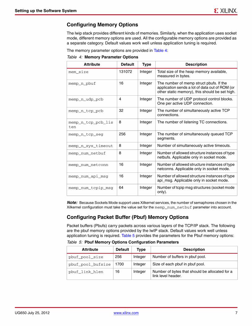
Setting up the Software System
Configuring Memory Options
The lwip stack provides different kinds of memories. Similarly, when the application uses socket mode, different memory options are used. All the configurable memory options are provided as a separate category. Default values work well unless application tuning is required.
The memory parameter options are provided in Table 4:
Note: Because Sockets Mode support uses Xilkernel services, the number of semaphores chosen in the Xilkernel configuration must take the value set for the memp_num_netbuf parameter into account.
Configuring Packet Buffer (Pbuf) Memory Options
Packet buffers (Pbufs) carry packets across various layers of the TCP/IP stack. The following are the pbuf memory options provided by the lwIP stack. Default values work well unless application tuning is required. Table 5 provides the parameters for the Pbuf memory options:
Table 4: Memory Parameter Options
Attribute Default Type Description
mem_size 131072 Integer Total size of the heap memory available, measured in bytes.
memp_n_pbuf 16 Integer The number of memp struct pbufs. If the application sends a lot of data out of ROM (or other static memory), this should be set high.
memp_n_udp_pcb 4 Integer The number of UDP protocol control blocks. One per active UDP connection.
memp_n_tcp_pcb 32 Integer The number of simultaneously active TCP connections.
memp_n_tcp_pcb_listen
8 Integer The number of listening TC connections.
memp_n_tcp_seg 256 Integer The number of simultaneously queued TCP segments.
memp_n_sys_timeout 8 Integer Number of simultaneously active timeouts.
memp_num_netbuf 8 Integer Number of allowed structure instances of type netbufs. Applicable only in socket mode.
memp_num_netconn 16 Integer Number of allowed structure instances of type netconns. Applicable only in socket mode.
memp_num_api_msg 16 Integer Number of allowed structure instances of type api_msg. Applicable only in socket mode.
memp_num_tcpip_msg 64 Integer Number of tcpip msg structures (socket mode only).
Table 5: Pbuf Memory Options Configuration Parameters
Attribute Default Type Description
pbuf_pool_size 256 Integer Number of buffers in pbuf pool.
pbuf_pool_bufsize 1700 Integer Size of each pbuf in pbuf pool.
pbuf_link_hlen 16 Integer Number of bytes that should be allocated for a link level header.
UG650 July 25, 2012 www.xilinx.com 7

Setting up the Software System
Configuring ARP Options
Table 6 provides the parameters for the ARP options. Default values work well unless application tuning is required.
Configuring IP Options
Table 7 provides the IP parameter options. Default values work well unless application tuning is required.
Configuring ICMP Options
Table 8 provides the parameter for ICMP protocol option. Default values work well unless application tuning is required.
Table 6: ARP Options Configuration Parameters
Attribute Default Type Description
arp_table_size 10 Integer Number of active hardware address IP address pairs cached.
arp_queueing 1 Integer If enabled outgoing packets are queued during hardware address resolution. This attribute can have two values: 0 or 1.
Table 7: IP Configuration Parameter Options
Attribute Default Type Description
ip_forward 0 Integer Set to 1 for enabling ability to forward IP packets across network interfaces. If running lwIP on a single network interface, set to 0. This attribute can have two values: 0 or 1.
ip_options 0 Integer When set to 1, IP options are allowed (but not parsed). When set to 0, all packets with IP options are dropped. This attribute can have two values: 0 or 1.
ip_reassembly 1 Integer Reassemble incoming fragmented IP packets.
ip_frag 1 Integer Fragment outgoing IP packets if their size exceeds MTU.
ip_reass_bufsize 5760 Integer Reassembly Buffer size.
ip_frag_max_mtu 1500 Integer Assumed max MTU on any interface for IP fragmented buffer.
ip_default_ttl 255 Integer Global default TTL used by transport layers.
Table 8: ICMP Configuration Parameter Option
Attribute Default Type Description
icmp_ttl 255 Integer ICMP TTL value.For GEM cores (for Zynq) there is no support for ICMP in the hardware.
8 www.xilinx.com UG650 July 25, 2012

Setting up the Software System
Configuring IGMP Options
The IGMP protocol is supported by lwip stack. When set true, the following option enables the IGMP protocol.
Configuring UDP Options
Table 10 provides UDP protocol options. Default values work well unless application tuning is required.
Configuring TCP Options
Table 11 provides the TCP protocol options. Default values work well unless application tuning is required.
Configuring DHCP Options
The DHCP protocol is supported by lwip stack. Table 12 provides DHCP protocol options. Default values work well unless application tuning is required.
Table 9: IGMP Configuration Parameter Option
Attribute Default Type Description
imgp_options false Boolean Specify whether IGMP is required.
Table 10: UDP Configuration Parameter Options
Attribute Default Type Description
lwip_udp true Boolean Specify whether UDP is required.
udp_ttl 255 Integer UDP TTL value.
Table 11: TCP Options Configuration Parameters
Attribute Default Type Description
lwip_tcp true Boolean Require TCP.
tcp_ttl 255 Integer TCP TTL value.
tcp_wnd 2048 Integer TCP Window size in bytes.
tcp_maxrtx 12 Integer TCP Maximum retransmission value.
tcp_synmaxrtx 4 Integer TCP Maximum SYN retransmission value.
tcp_queue_ooseq 1 Integer Accept TCP queue segments out of order. Set to 0 if your device is low on memory.
tcp_mss 1460 Integer TCP Maximum segment size.
tcp_snd_buf 8192 Integer TCP sender buffer space in bytes.
Table 12: DHCP Options Configuration Parameters
Attribute Default Type Description
lwip_dhcp false Boolean Specify whether DHCP is required.
dhcp_does_arp_check false Boolean Specify whether ARP checks on offered addresses.
UG650 July 25, 2012 www.xilinx.com 9

Setting up the Software System
Configuring the Stats Option
lwIP stack has been written to collect statistics, such as the number of connections used; amount of memory used; and number of semaphores used, for the application. The library provides the stats_display() API to dump out the statistics relevant to the context in which the call is used. The stats option can be turned on to enable the statistics information to be collected and displayed when the stats_display API is called from user code. Use the following option to enable collecting the stats information for the application.
Configuring the Debug Option
lwIP provides debug information. Table 14 lists all available options.
Software APIs
lwIP provides two different APIs: RAW mode and Socket mode.
Raw API
The Raw API is callback based. Applications obtain access directly into the TCP stack and vice-versa. As a result, there is no unnecessary copying of data, and using the Raw API provides excellent performance at the price of compatibility with other TCP stacks.
Xilinx Adapter Requirements when using RAW API
In addition to the lwIP RAW API, the Xilinx adapters provide the xemacif_input utility function for receiving packets. This function must be called at frequent intervals to move the received packets from the interrupt handlers to the lwIP stack. Depending on the type of packet received, lwIP then calls registered application callbacks.
Raw API File
The $XILINX_EDK/sw/ThirdParty/sw_services/lwip140_v1_02_a/src/lwip-1.4.0/doc/rawapi.txt file describes the lwIP Raw API.
Table 13: Statistics Option Configuration Parameters
Attribute Description Type Default
lwip_stats Turn on lwIP Statistics int 0
Table 14: Debug Option Configuration Parameters
Attribute Default Type Description
lwip_debug false Boolean Turn on/off lwIP debugging.
ip_debug false Boolean Turn on/off IP layer debugging.
tcp_debug false Boolean Turn on/off TCP layer debugging.
udp_debug false Boolean Turn on/off UDP layer debugging.
icmp_debug false Boolean Turn on/off ICMP protocol debugging.
igmp_debug false Boolean Turn on/off IGMP protocol debugging.
netif_debug false Boolean Turn on/off network interface layer debugging.
sys_debug false Boolean Turn on/off sys arch layer debugging.
pbuf_debug false Boolean Turn on/off pbuf layer debugging
10 www.xilinx.com UG650 July 25, 2012

Setting up the Software System
Socket API
The lwIP socket API provides a BSD socket-style API to programs. This API provides an execution model that is a blocking, open-read-write-close paradigm. Socket API cannot be used for Gigabit Ethernet MAC on Cortex-A9 (Zynq) systems.
Xilinx Adapter Requirements when using Socket API
Applications using the Socket API with Xilinx adapters need to spawn a separate thread called xemacif_input_thread. This thread takes care of moving received packets from the interrupt handlers to the tcpip_thread of the lwIP. Application threads that use lwIP must be created using the lwIP sys_thread_new API. Internally, this function makes use of the pthread_create() function in Xilkernel to create a new thread. It also initializes specific per-thread timeout structures necessary for lwIP operation.
Xilkernel scheduling policy when using Socket API
lwIP in socket mode requires the use of the Xilkernel, which provides two policies for thread scheduling: round-robin and priority based:
There are no special requirements when round-robin scheduling policy is used because all threads receive the same time quanta.
With priority scheduling, care must be taken to ensure that lwIP threads are not starved. lwIP internally launches all threads at the priority level specified in socket_mode_thread_prio. In addition, application threads must launch xemacif_input_thread. The priorities of both xemacif_input_thread, and the lwIP internal threads (socket_mode_thread_prio) must be high enough in relation to the other application threads so that they are not starved.
Using Xilinx Adapter Helper Functions
The Xilinx adapters provide the following helper functions to simplify the use of the lwIP APIs.
void lwip_init()
This function provides a single initialization function for the lwIP data structures. This replaces specific calls to initialize stats, system, memory, pbufs, ARP, IP, UDP, and TCP layers.
struct netif *xemac_add (struct netif *netif, struct ip_addr *ipaddr, struct ip_addr *netmask, struct ip_addr *gw, unsigned char *mac_ethernet_address unsigned mac_baseaddr)
The xemac_add function provides a unified interface to add any Xilinx EMAC IP as well as GEM core. This function is a wrapper around the lwIP netif_add function that initializes the network interface ‘netif’ given its IP address ipaddr, netmask, the IP address of the gateway, gw, the 6 byte ethernet address mac_ethernet_address, and the base address, mac_baseaddr, of the xps_ethernetlite or xps_ll_temac MAC core.
UG650 July 25, 2012 www.xilinx.com 11
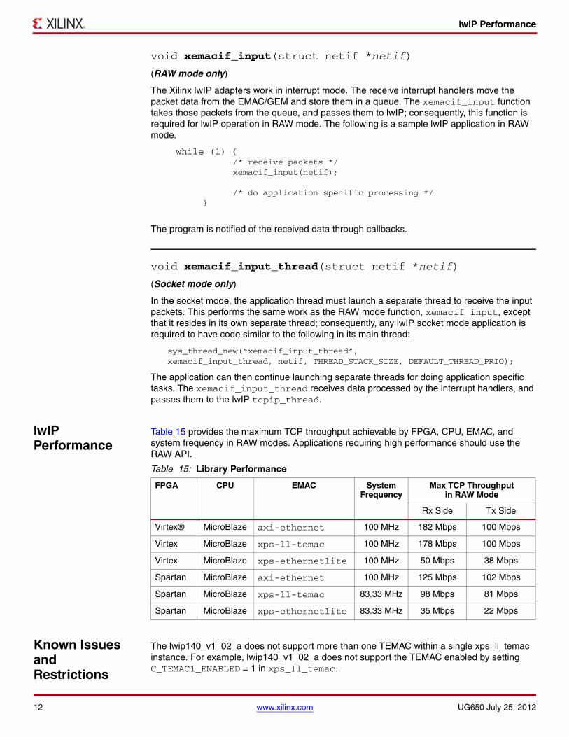
lwIP Performance
void xemacif_input(struct netif *netif)
(RAW mode only)
The Xilinx lwIP adapters work in interrupt mode. The receive interrupt handlers move the packet data from the EMAC/GEM and store them in a queue. The xemacif_input function takes those packets from the queue, and passes them to lwIP; consequently, this function is required for lwIP operation in RAW mode. The following is a sample lwIP application in RAW mode.
while (1) { /* receive packets */ xemacif_input(netif);
/* do application specific processing */ }
The program is notified of the received data through callbacks.
void xemacif_input_thread(struct netif *netif)
(Socket mode only)
In the socket mode, the application thread must launch a separate thread to receive the input packets. This performs the same work as the RAW mode function, xemacif_input, except that it resides in its own separate thread; consequently, any lwIP socket mode application is required to have code similar to the following in its main thread:
sys_thread_new(“xemacif_input_thread”, xemacif_input_thread, netif, THREAD_STACK_SIZE, DEFAULT_THREAD_PRIO);
The application can then continue launching separate threads for doing application specific tasks. The xemacif_input_thread receives data processed by the interrupt handlers, and passes them to the lwIP tcpip_thread.
lwIP Performance
Table 15 provides the maximum TCP throughput achievable by FPGA, CPU, EMAC, and system frequency in RAW modes. Applications requiring high performance should use the RAW API.
Known Issues and Restrictions
The lwip140_v1_02_a does not support more than one TEMAC within a single xps_ll_temac instance. For example, lwip140_v1_02_a does not support the TEMAC enabled by setting C_TEMAC1_ENABLED = 1 in xps_ll_temac.
Table 15: Library Performance
FPGA CPU EMAC System Frequency
Max TCP Throughput in RAW Mode
Rx Side Tx Side
Virtex® MicroBlaze axi-ethernet 100 MHz 182 Mbps 100 Mbps
Virtex MicroBlaze xps-ll-temac 100 MHz 178 Mbps 100 Mbps
Virtex MicroBlaze xps-ethernetlite 100 MHz 50 Mbps 38 Mbps
Spartan MicroBlaze axi-ethernet 100 MHz 125 Mbps 102 Mbps
Spartan MicroBlaze xps-ll-temac 83.33 MHz 98 Mbps 81 Mbps
Spartan MicroBlaze xps-ethernetlite 83.33 MHz 35 Mbps 22 Mbps
12 www.xilinx.com UG650 July 25, 2012

API Examples
API Examples Sample applications using the RAW API and Socket API are available on the Xilinx website. This section provides pseudo code that illustrates the typical code structure.
RAW API
Applications using the RAW API are single threaded, and have the following broad structure:
int main(){
struct netif *netif, server_netif;struct ip_addr ipaddr, netmask, gw;
/* the MAC address of the board. * This should be unique per board/PHY */unsigned char mac_ethernet_address[] =
{0x00, 0x0a, 0x35, 0x00, 0x01, 0x02};
lwip_init();
/* Add network interface to the netif_list, * and set it as default */if (!xemac_add(netif, &ipaddr, &netmask,
&gw, mac_ethernet_address, EMAC_BASEADDR)) {printf(“Error adding N/W interface\n\r”);return -1;
}netif_set_default(netif);
/* now enable interrupts */platform_enable_interrupts();
/* specify that the network if is up */netif_set_up(netif);
/* start the application, setup callbacks */start_application();
/* receive and process packets */while (1) {
xemacif_input(netif);/* application specific functionality */transfer_data();
}}
RAW API works primarily using asynchronously called Send and Receive callbacks.
UG650 July 25, 2012 www.xilinx.com 13

API Examples
Socket API
In socket mode, applications specify a static list of threads that Xilkernel spawns on startup in the Xilkernel software platform settings. Assuming that main_thread() is a thread specified to be launched by Xilkernel, then the following pseudo-code illustrates a typical socket mode program structure
void network_thread(void *p){
struct netif *netif;struct ip_addr ipaddr, netmask, gw;
/* the MAC address of the board. * This should be unique per board/PHY */unsigned char mac_ethernet_address[] =
{0x00, 0x0a, 0x35, 0x00, 0x01, 0x02};
netif = &server_netif;
/* initialize IP addresses to be used */IP4_ADDR(&ipaddr,192,168,1,10);IP4_ADDR(&netmask,255,255,255,0);IP4_ADDR(&gw,192,168,1,1);
/* Add network interface to the netif_list, * and set it as default */if (!xemac_add(netif, &ipaddr, &netmask,
&gw, mac_ethernet_address, EMAC_BASEADDR)) {
printf(“Error adding N/W interface\n\r”);return;
}netif_set_default(netif);
/* specify that the network if is up */netif_set_up(netif);
/* start packet receive thread - required for lwIP operation */sys_thread_new(“xemacif_input_thread”, xemacif_input_thread,
netif,THREAD_STACKSIZE, DEFAULT_THREAD_PRIO);
/* now we can start application threads *//* start webserver thread (e.g.) */sys_thread_new(“httpd” web_application_thread, 0,
THREAD_STACKSIZE DEFAULT_THREAD_PRIO);}
int main_thread(){
/* initialize lwIP before calling sys_thread_new */lwip_init();
/* any thread using lwIP should be created using * sys_thread_new() */sys_thread_new(“network_thread” network_thread, NULL,
THREAD_STACKSIZE DEFAULT_THREAD_PRIO);
return 0;}
14 www.xilinx.com UG650 July 25, 2012

re
LibXil Isf Library Overview
The LibXil Isf library:
• Allows the user to Write, Read, and Erase the Serial Flash.
• Allows protection of the data stored in the Serial Flash from unwarranted modification by enabling the Sector Protection feature.
• Supports multiple instances of Serial Flash at a time, provided they are of the same device family (Atmel, Intel, STM, Winbond, SST, or Spansion) as the device family is selected at compile time.
Note: Spansion (S25FLXX) devices are not tested. Support for this family of devices is limited to the common commands supported by the other flash families.
• Allows the user application to perform Control operations on Intel, STM, Winbond, SST, and Spansion Serial Flash.
• Requires the underlying hardware platform to contain the xps_spi, axi_spi, axi_quad_spi, ps7_spi, or ps7_qspi device for accessing the Serial Flash.
• Uses the Xilinx® SPI interface drivers in interrupt-driven mode or polled mode for communicating with the Serial Flash. In interrupt mode, the user application must acknowledge any associated interrupts from the Interrupt Controller.
• Requires the user application to track status of initiated operations when in interrupt mode; the transfer is initiated and the control is given back to the user application.
• Added support in the library for SPI PS and QSPI PS. User needs to select one of the interfaces at compile time.
UG652 July 25, 2012
LibXil Isf (v3.00.a)
UG652 July 25, 2012 www.xilinx.com 1
© 2012 Xilinx, Inc. XILINX, the Xilinx logo, Virtex, Spartan, ISE, and other designated brands included herein are trademarks of Xilinx in the United States and other countries. All other trademarks are the property of their respective owners.

Supported Devices
Supported Devices
Table 1 lists the supported Xilinx In-System Flash and external Serial Flash Memories.
Table 1: Xilinx In-System Flash and External Serial Flash Memories
Device Series Manufacturer
AT45DB011DAT45DB021DAT45DB041DAT45DB081DAT45DB161DAT45DB321DAT45DB642D
Atmel
S3316MBITS3332MBITS3364MBITM25P05_AM25P10_A
M25P20 M25P40M25P80M25P16 M25P32M25P64
M25P128N25Q32N25Q64
N25Q128
Intel/ST Microelectronics (STM)/Numonyx 1
W25Q16W25Q32W25Q64W25Q80
W25Q128W25X10W25X20W25X40W25X80W25X16W25X32W25X64
Winbond
S25FL004S25FL008S25FL016S25FL032S25FL064S25FL128S25FL129
Spansion 2
SST25WF080 SST
1. Intel and STM Serial Flash devices are now a part of Serial Flash devices provided by Numonyx.2. Spansion (S25FLXX) devices are not tested. Support for this family of devices is limited to the
common commands supported by the other flash families.
2 www.xilinx.com UG652 July 25, 2012

LibXil Isf Library APIs
LibXil Isf Library APIs
This section provides a linked summary and detailed descriptions of the LibXil Isf library APIs.
API Summary
The following is a summary list of APIs provided by the LibXil Isf library. The list is linked to the API description. Click the API name to go to the description.
int XIsf_Initialize(XIsf *InstancePtr, XSpi *SpiInstPtr, u32 SlaveSelect, u8 *WritePtr)int XIsf_GetStatus(XIsf *InstancePtr, u8 *ReadPtr)int XIsf_GetStatusReg2(XIsf *InstancePtr, u8 *ReadPtr)int XIsf_GetDeviceInfo(XIsf *InstancePtr, u8 *ReadPtr)int XIsf_Read(XIsf *InstancePtr, XIsf_ReadOperation Operation, void *OpParamPtr)int XIsf_Write(XIsf *InstancePtr, XIsf_WriteOperation Operation, void *OpParamPtr)int XIsf_Erase(XIsf *InstancePtr, XIsf_EraseOperation Operation, u32 Address)int XIsf_SectorProtect(XIsf *InstancePtr, XIsf_SpOperation Operation, u8 *BufferPtr)int XIsf_WriteEnable(XIsf *InstancePtr, u8 WriteEnable)int XIsf_Ioctl (XIsf *InstancePtr, XIsf_IoctlOperation Operation)int XIsf_SetSpiConfiguration(XIsf *InstancePtr, XIsf_Iface *SpiInstPtr, u32 Options, u8 PreScaler)inline void XIsf_SetTransferMode(XIsf *InstancePtr, u8 Mode)
UG652 July 25, 2012 www.xilinx.com 3

LibXil Isf Library APIs
LibXil Isf API Descriptions
int XIsf_Initialize(XIsf *InstancePtr, XSpi *SpiInstPtr, u32 SlaveSelect, u8 *WritePtr)
Parameters InstancePtr is a pointer to the XIsf instance.SpiInstPtr is a pointer to the XSpi instance to be worked on.SlaveSelect is a 32-bit mask with a 1 in the bit position of the slave being selected. Only one slave can be selected at a time.WritePtr is a pointer to the buffer allocated by the user to be used by the In-system and Serial Flash Library to perform any read/write operations on the Serial Flash device.User applications must initialize the Isf library by passing the address of this buffer to the Initialization API.For Write operations:• A minimum of one byte and a maximum of ISF_PAGE_SIZE bytes can be
written to the Serial Flash, through a single Write operation.• The buffer size must be equal to the number of bytes to be written to the Serial
Flash + XISF_CMD_MAX_EXTRA_BYTES, and must be large enough for use across the applications that use a common instance of the Serial Flash.
For Non Write operations:• The buffer size must be equal to XISF_CMD_MAX_EXTRA_BYTES.
Returns XST_SUCCESS upon success.XST_DEVICE_IS_STOPPED if the device must be started before transferring data.XST_FAILURE upon failure.
Description The geometry of the underlying Serial Flash is determined by reading the Joint Electron Device Engineering Council (JEDEC) Device Information and the Serial Flash Status Register.When called, this API initializes the SPI interface with default settings. With custom settings, the user should call XIsf_SetSpiConfiguration() before calling this API.
Note: The XIsf_Initialize() API is a blocking call (for both polled mode and interrupt mode of the SPI driver). It reads the JEDEC information of the device and waits till the transfer is complete before checking if the information is valid.
Support multiple instances of Serial Flash at a time, provided they are of the same device family (either Atmel, Intel, STM, Winbond, or SST) as the device family is selected at compile time.
Includes xilisf.h
4 www.xilinx.com UG652 July 25, 2012

LibXil Isf Library APIs
int XIsf_GetStatus(XIsf *InstancePtr, u8 *ReadPtr)
int XIsf_GetStatusReg2(XIsf *InstancePtr, u8 *ReadPtr)
int XIsf_GetDeviceInfo(XIsf *InstancePtr, u8 *ReadPtr)
Parameters InstancePtr is a pointer to the XIsf instance.ReadPtr is a pointer to the memory where the Status Register content is copied.
Returns XST_SUCCESS upon successXST_FAILURE upon failure
Description Reads the Serial Flash Status Register.
Note: The status register content is stored at the second byte pointed by the ReadPtr.
Includes xilisf.h
Parameters InstancePtr is a pointer to the XIsf instance.ReadPtr is a pointer to the memory where the Status Register content is copied.
Returns XST_SUCCESS upon successXST_FAILURE upon failure
Description Reads the Serial Flash Status Register2. this API is valid only for Windbond (W25QXX) flash devices.
Note: The status register content is stored at the second byte pointed by the ReadPtr.
Includes xilisf.h
Parameters InstancePtr is a pointer to the XIsf instance.ReadPtr is a pointer to the memory where the Device information is copied.
Returns XST_SUCCESS upon success.XST_FAILURE upon failure.
Description Reads the JEDEC information of the Serial Flash.
Note: The Device information is stored at the second byte pointed by the ReadPtr.
Includes xilisf.h
UG652 July 25, 2012 www.xilinx.com 5

LibXil Isf Library APIs
int XIsf_Read(XIsf *InstancePtr, XIsf_ReadOperation Operation, void *OpParamPtr)Parameters InstancePtr is a pointer to the XIsf instance.
Operation is the type of the read operation to be performed on the Serial Flash.The Operation options are:XISF_READ: Normal ReadXISF_FAST_READ: Fast ReadXISF_PAGE_TO_BUF_TRANS: Page to Buffer TransferXISF_BUFFER_READ: Buffer ReadXISF_FAST_BUFFER_READ: Fast Buffer ReadXISF_OTP_READ: One Time Programmable Area (OTP) Read.XISF_DUAL_OP_FAST_READ: Dual Output Fast Read
XISF_DUAL_IO_FAST_READ: Dual Input/Output Fast Read
XISF_QUAD_OP_FAST_READ: Quad Output Fast Read
XISF_QUAD_IO_FAST_READ: Quad Input/Output Fast Read
OpParamPtr is the pointer to structure variable which contains operational parameter of specified Operation. This parameter type is dependent on the type of Operation to be performed.When specifying Normal Read (XISF_READ), Fast Read (XISF_FAST_READ) and One Time Programmable Area Read(XISF_OTP_READ), Dual Output Fast Read(XISF_DUAL_OP_FAST_READ), Dual Input/Output Fast Read(XISF_DUAL_IO_FAST_READ), Quad Output Fast Read(XISF_QUAD_OP_FAST_READ)and Quad Input/Output Fast Read (XISF_QUAD_IO_FAST_READ): • OpParamPtr must be of type struct XIsf_ReadParam.• OpParamPtr->Address is the start address in the Serial Flash.• OpParamPtr->ReadPtr is a pointer to the memory where the
data read from the Serial Flash is stored.• OpParamPtr->NumBytes is number of bytes to read.• OpParamPtr->NumDummyBytes is the number of dummy bytes
to be transmitted for the Read command. This parameter is only used in case of Dual and Quad reads.
Normal Read and Fast Read operations are supported for Atmel, Intel, STM, Winbond, SST, and Spansion Serial Flash. Dual and quad reads are supported for Winbond (W25QXX),Numonyx (N25QXX) and Spansion (S25FL129) quad flash. OTP Read operation is only supported in Intel Serial Flash.When specifying Page To Buffer Transfer (XISF_PAGE_TO_BUF_TRANS):• OpParamPtr must be of type struct
XIsf_FlashToBufTransferParam.• OpParamPtr->BufferNum specifies the internal SRAM Buffer of
the Serial Flash. The valid values are XISF_PAGE_BUFFER1 or XISF_PAGE_BUFFER2. XISF_PAGE_BUFFER2 is not valid in the case of AT45DB011D Flash as it contains a single buffer.
• OpParamPtr->Address is start address in the Serial Flash.This operation is only supported in Atmel Serial Flash.
6 www.xilinx.com UG652 July 25, 2012

LibXil Isf Library APIs
XIsf_Read (continued)
Parameters When specifying Buffer Read (XISF_BUFFER_READ) and Fast Buffer Read (XISF_FAST_BUFFER_READ):• OpParamPtr must be of type struct XIsf_BufferReadParam.• OpParamPtr->BufferNum specifies the internal SRAM Buffer of the
Serial Flash. The valid values are XISF_PAGE_BUFFER1 or XISF_PAGE_BUFFER2. XISF_PAGE_BUFFER2 is not valid in the case of AT45DB011D Flash as it contains a single buffer.
• OpParamPtr->ReadPtr is pointer to the memory where the data read from the SRAM buffer is to be stored.
• OpParamPtr->ByteOffset is byte offset in the SRAM buffer from where the first byte is read.
• OpParamPtr->NumBytes is the number of bytes to be read from the Buffer.
These operations are supported only in Atmel Serial Flash.
Returns XST_SUCCESS upon success.XST_FAILURE upon failure.
Description Reads the data from the Serial Flash.
Note: Application must fill the structure elements of the third argument and pass its pointer by type casting it with void pointer.
The valid data is available from the fourth location pointed to by the ReadPtr for Normal Read and Buffer Read operations.
The valid data is available from the fifth location pointed to by the ReadPtr for Fast Read, Fast Buffer Read, and OTP Read operations. The valid data is available from the (4 + NumDummyBytes) location pointed to by ReadPtr for Dual/Quad Read operations.
Includes xilisf.h
UG652 July 25, 2012 www.xilinx.com 7
LibXil Isf Library APIs
int XIsf_Write(XIsf *InstancePtr, XIsf_WriteOperation Operation, void *OpParamPtr)
Parameters InstancePtr is a pointer to the XIsf instance.Operation is the type of write operation to be performed on the Serial Flash.The Operation options are:• XISF_WRITE: Normal Write• XISF_DUAL_IP_PAGE_WRITE: Dual Input Fast Program • XISF_DUAL_IP_EXT_PAGE_WRITE: Dual Input Extended Fast Program • XISF_QUAD_IP_PAGE_WRITE: Quad Input Fast Program• XISF_QUAD_IP_EXT_PAGE_WRITE: Quad Input Extended Fast Program• XISF_AUTO_PAGE_WRITE: Auto Page Write• XISF_BUFFER_WRITE: Buffer Write• XISF_BUF_TO_PAGE_WRITE_WITH_ERASE: Buffer to Page Transfer with
Erase• XISF_BUF_TO_PAGE_WRITE_WITHOUT_ERASE: Buffer to Page Transfer
without Erase• XISF_WRITE_STATUS_REG: Status Register Write• XISF_WRITE_STATUS_REG2: 2 byte Status Register Write• XISF_OTP_WRITE: OTP Write.OpParamPtr is the pointer to a structure variable which contains operational parameters of specified operation.This parameter type is dependant upon the value of first argument (Operation).When specifying Normal Write (XISF_WRITE): Dual Input Fast Program (XISF_DUAL_IP_PAGE_WRITE), Dual Input Extended Fast Program (XISF_DUAL_IP_EXT_PAGE_WRITE), Quad Input Fast Program (XISF_QUAD_IP_PAGE_WRITE), Quad Input Extended Fast Program (XISF_QUAD_IP_EXT_PAGE_WRITE):
• OpParamPtr must be of type struct XIsf_WriteParam.• OpParamPtr->Address is the start address in the Serial Flash.• OpParamPtr->WritePtr is a pointer to the data to be written to the Serial
Flash.• OpParamPtr->NumBytes is the number of bytes to be written to the Serial
Flash.This operation is supported for Atmel, Intel, STM, Winbond, and Spansion Serial Flash.For SST, only normal write is applicable.
8 www.xilinx.com UG652 July 25, 2012

LibXil Isf Library APIs
XIsf_Write (continued)
Parameters When specifying the Auto Page Write (XISF_AUTO_PAGE_WRITE):• OpParamPtr must be of 32 bit unsigned integer variable. This is the address of page
number in the Serial Flash which is to be refreshed.This operation is only supported in Atmel Serial Flash.When specifying the Buffer Write (XISF_BUFFER_WRITE): • OpParamPtr must be of type struct XIsf_BufferWriteParam.• OpParamPtr->BufferNum specifies the internal SRAM Buffer of the Serial Flash. The
valid values are XISF_PAGE_BUFFER1 or XISF_PAGE_BUFFER2. XISF_PAGE_BUFFER2 is not valid in the case of AT45DB011D Flash as it contains a single buffer.
• OpParamPtr->WritePtr is a pointer to the data to be written to the Serial Flash SRAM Buffer.
• OpParamPtr->ByteOffset is byte offset in the buffer from where the data is to be written.
• OpParamPtr->NumBytes is number of bytes to be written to the Buffer.This operation is supported only for Atmel Serial Flash.When specifying Buffer To Memory Write With Erase (XISF_BUF_TO_PAGE_WRITE_WITH_ERASE) or Buffer To Memory Write Without Erase (XISF_BUF_TO_PAGE_WRITE_WITHOUT_ERASE):• OpParamPtr must be of type struct XIsf_BufferToFlashWriteParam.• OpParamPtr->BufferNum specifies the internal SRAM Buffer of the Serial Flash. The
valid values are XISF_PAGE_BUFFER1 or XISF_PAGE_BUFFER2. XISF_PAGE_BUFFER2 is not valid in the case of AT45DB011D Flash as it contains a single buffer.
• OpParamPtr->Address is starting address in the Serial Flash memory from where the data is to be written.
These operations are only supported in Atmel Serial Flash.When specifying Write Status Register (XISF_WRITE_STATUS_REG), the OpParamPtr must be an 8-bit unsigned integer variable. This is the value to be written to the Status Register.This operation is supported in Intel, STM, SST, and Winbond Serial Flash only.When specifying Write 2 Byte Status Register (XISF_WRITE_STATUS_REG2), the OpParamPtr must be of type (u8 *) and should point to two 8 bit unsigned integer values. This is the value to be written to the 16 bit Status Register
Note: This operation is supported only in Winbond (W25QXX) Serial Flash.
When specifying One Time Programmable Area Write (XISF_OTP_WRITE):• OpParamPtr must be of type struct XIsf_WriteParam.• OpParamPtr->Address is the address in the SRAM Buffer of the Serial Flash to which
the data is to be written.• OpParamPtr->WritePtr is a pointer to the data to be written to the Serial Flash.• OpParamPtr->NumBytes should be set to 1 when performing OTPWrite operation.This operation is only supported in Intel Serial Flash.
Returns XST_SUCCESS upon success.XST_FAILURE upon failure.
Description Writes data to the Serial Flash.
Note: Application must fill the structure elements of the third argument and pass its pointer by type casting it with void pointer.
For Intel, STM, Winbond, SST, and Spansion Serial Flash the user application must call the XIsf_WriteEnable() API by passing XISF_WRITE_ENABLE as an argument before calling the XIsf_Write() API.
Includes xilisf.h
UG652 July 25, 2012 www.xilinx.com 9

LibXil Isf Library APIs
int XIsf_Erase(XIsf *InstancePtr, XIsf_EraseOperation Operation, u32 Address)
Parameters InstancePtr is a pointer to the XIsf instance.Operation is the type of Erase operation to be performed on the Serial Flash.The different operations are• XISF_PAGE_ERASE: Page Erase• XISF_BLOCK_ERASE: Block Erase• XISF_SECTOR_ERASE: Sector Erase• XISF_BULK_ERASE: Bulk EraseAddress is the address of the Page/Block/Sector to be erased. The address can be either Page address, Block address or Sector address based on the Erase operation to be performed.
Returns XST_SUCCESS upon success.XST_FAILURE upon failure.
Description Erases the contents of the specified memory in the Serial Flash.
Note: The erased bytes will read as 0xFF.
For Intel, STM, Winbond, and Spansion Serial Flash the user application must call XIsf_WriteEnable() API by passing XISF_WRITE_ENABLE as an argument before calling the XIsf_Erase() API.Atmel, Intel, STM Winbond, Numonyx (N25QXX), and Spansion Serial Flash devices support Sector/Block/Bulk Erase operations.SST devices support all Erase commands.
Includes xilisf.h
10 www.xilinx.com UG652 July 25, 2012

LibXil Isf Library APIs
int XIsf_SectorProtect(XIsf *InstancePtr, XIsf_SpOperation Operation, u8 *BufferPtr)
int XIsf_WriteEnable(XIsf *InstancePtr, u8 WriteEnable)
Parameters InstancePtr is a pointer to the XIsf instance.Operation is the type of Sector Protect operation to be performed on the Serial Flash.The Operation options are• XISF_SPR_READ: Read Sector Protection Register• XISF_SPR_WRITE: Write Sector Protection Register• XISF_SPR_ERASE: Erase Sector Protection Register• XISF_SP_ENABLE: Enable Sector Protection• XISF_SP_DISABLE: Disable Sector ProtectionBufferPtr is a pointer to the memory where the SPR content is read to/written from. This argument can be NULL if the Operation is SprErase, SpEnable and SpDisable.
Returns XST_SUCCESS upon success.XST_FAILURE upon failure.
Description Performs Sector Protect operations.
Note: The SPR content is stored at the fourth location pointed by the BufferPtr when performing XISF_SPR_READ operation.
For Intel, STM, Winbond, and Spansion Serial Flash devices the user application must call the XIsf_WriteEnable() API by passing XISF_WRITE_ENABLE as an argument, before calling the XIsf_SectorProtect() API, for Sector Protect Register Write (XISF_SPR_WRITE) operation.Atmel Flash supports all these Sector Protect operations.Intel, STM, Winbond, and Spansion support only Sector Protect Read and Sector Protect Write operations.
Includes xilisf.h
Parameters InstancePtr is a pointer to the XIsf instance.WriteEnable specifies whether to enable (XISF_CMD_ENABLE_WRITE) or disable (XISF_CMD_DISABLE_WRITE) the writes to the Serial Flash.
Returns XST_SUCCESS upon success.XST_FAILURE upon failure.
Description Enables/Disables writes to the Intel, STM, Winbond, SST, and Spansion Serial Flash.
Note: If this API is called for Atmel Flash, XST_FAILURE is returned.
Includes xilisf.h
UG652 July 25, 2012 www.xilinx.com 11

LibXil Isf Library APIs
int XIsf_Ioctl (XIsf *InstancePtr, XIsf_IoctlOperation Operation)
int XIsf_SetSpiConfiguration(XIsf *InstancePtr, XIsf_Iface *SpiInstPtr, u32 Options, u8 PreScaler)
inline void XIsf_SetTransferMode(XIsf *InstancePtr, u8 Mode)
This API sets the interrupt/polling mode of transfer.
Parameters InstancePtr is a pointer to the XIsf instance.Operation is the type of Control operation to be performed on the Serial Flash.The control Operations options are:• XISF_RELEASE_DPD: Release from Deep Power Down (DPD) Mode• XISF_ENTER_DPD: Enter DPD Mode• XISF_CLEAR_SR_FAIL_FLAGS: Clear the Status Register Fail Flags.
Returns XST_SUCCESS upon success.XST_FAILURE upon failure.
Description This API configures and controls the Intel, STM, Winbond, and Spansion Serial Flash.
Note: Atmel Serial Flash does not support any of these operations.
Intel Serial Flash support Enter/Release from DPD Mode and Clear Status Register Fail Flags.STM, Winbond, and Spansion Serial Flash support Enter/Release from DPD Mode.Winbond (W25QXX) supports Enable High performance mode.
Includes xilisf.h
Parameters InstancePtr is a pointer to the XIsf instance.SpiInstPtr is a pointer to the XIsf_Iface instance to be worked on.Options contains specified options to be set.PreScaler is the value of the clock prescaler to set.
Returns XST_SUCCESS upon success.XST_FAILURE upon failure.
Description Sets the configuration of SPI. This API can be called before calling XIsf_Initialize() to operate the SPI interface in a mode other than the default options mode.PreScaler is only applicable to PS SPI/QSPI.
Includes xilisf.h
Parameters InstancePtr is a pointer to the XIsf instance.Mode is the value to be set.
Returns None.
Description By default, the xilisf library is designed to operate in polling mode. User needs to call this API, if operating in Interrupt Mode.
12 www.xilinx.com UG652 July 25, 2012

Libgen Customization
Libgen Customization
The LibXil Isf library can be integrated with a system using the following snippet in the Microprocessor Software Specification (MSS) file.
BEGIN LIBRARYparameter LIBRARY_NAME = xilisfparameter LIBRARY_VER = 3.00.aparameter PROC_INSTANCE = microblaze_0parameter serial_flash_family = 1parameter serial_flash_interface = 1
END
Where:
- LIBRARY_NAME—Is the library name (xilisf).
- LIBRARY_VER—Is the library version (3.00.a).
- PROC_INSTANCE—Is the processor instance (microblaze_0|ppc405|ppc440 | ps7_cortexa9_0)
- serial_flash_family—Is a numerical value representing the serial flash family, where:
- 1 = Xilinx In-system Flash or Atmel Serial Flash
- 2 = Intel (Numonyx) S33 Serial Flash
- 3 = STM (Numonyx) M25PXX/N25QXX Serial Flash
- 4 = Winbond Serial Flash
- 5 = Spansion Serial Flash
- 6 = SST Serial Flash
- serial_flash_interface - Is a numerical value representing the serial flash interface, where:
- 1 = AXI SPI Interface
- 2 = SPI PS Interface
- 3 = QSPI PS Interface
UG652 July 25, 2012 www.xilinx.com 13

Additional Resources
Additional Resources
• Spartan-3AN FPGA In-System Flash User Guide (UG333):http://www.xilinx.com/support/documentation/user_guides/ug333.pdf
• Atmel Serial Flash Memory website (AT45XXXD):http://www.atmel.com/dyn/products/devices.asp?family_id=616#1802
• Intel (Numonyx) S33 Serial Flash Memory website (S33):http://www.numonyx.com/Documents/Datasheets/314822_S33_Discrete_DS.pdf
• STM (Numonyx) M25PXX Serial Flash Memory website (M25PXX): http://www.numonyx.com/en-US/MemoryProducts/NORserial/Pages/M25PTechnicalDocuments.aspx
• Winbond Serial Flash Page:http://www.winbond-usa.com/hq/enu/ProductAndSales/ProductLines/FlashMemory/SerialFlash/
• Spansion website: http://www.spansion.com/Support/Pages/DatasheetsIndex.aspx
• SST SST25WF080: http://www.sst.com/dotAsset/40369.pdf
Revision History
The following table shows the revision history for this document:
Date Version Description of Revisions
07/06/2011 v2.03.a EDK Release 13.2: Added explicit device numbers.
10/19/2011 v2.04.a EDK Release 13.3: • Added Spansion Serial Flash support. • Added the requirement for axi_spi, or axi_quad_spi devices. • APIs throughout the documents specify the inclusion of
Spansion, and exceptions for Windbond (W25QXX).
07/25/2012 v3.00.a EDK Release 14.2:• Updated to support interfaces SPI PS and QSPI PS.• Added support to SST flash.
14 www.xilinx.com UG652 July 25, 2012

Overview The XilFlash library provides read/write/erase/lock/unlock features to access a parallel flash device. Flash device family specific functionality are also supported by the library. This library requires the underlying hardware platform to contain the following:
• xps_mch_emc or similar core for accessing the flash.
This library implements the functionality for flash memory devices that conform to the "Common Flash Interface" (CFI) standard. CFI allows a single flash library to be used for an entire family of parts.This library supports Intel and AMD CFI compliant flash memory devices.
All the calls in the library are blocking in nature in that the control is returned back to user only after the current operation is completed successfully or an error is reported.
The following common APIs are supported for all flash devices:
• Initialize
• Read
• Write
• Erase
• Lock
• UnLock
• IsReady
• Reset
• Device specific control
You must call the “int XFlash_Initialize (XFlash *InstancePtr, u32 BaseAddress, u8 BusWidth, int IsPlatformFlash)” API before calling any other API in this library.
XilFlash Library APIs
This section provides a linked summary and detailed descriptions of the LibXil Flash library APIs.
API Summary
The following is a summary list of APIs provided by the LibXil Flash library. The list is linked to the API description. Click on the API name to go to the description.
UG651 July 25, 2012
LibXil Flash (v3.02.a)
int XFlash_Initialize (XFlash *InstancePtr, u32 BaseAddress, u8 BusWidth, int IsPlatformFlash)int XFlash_Reset (XFlash *InstancePtr)int XFlash_Read (XFlash *InstancePtr, u32 Offset, u32 Bytes, void *DestPtr)int XFlash_Write (XFlash *InstancePtr, u32 Offset, u32Bytes, void *SrcPtr)int XFlash_Erase (XFlash *InstancePtr, u32 Offset, u32 Bytes)int XFlash_Lock (XFlash *InstancePtr, u32 Offset, u32 Bytes)int XFlash_UnLock (XFlash *InstancePtr, u32 Offset, u32 Bytes)int XFlash_DeviceControl (XFlash *InstancePtr, u32 Command, DeviceControl *Parameters)int XFlash_IsReady (XFlash *InstancePtr)
UG651 July 25, 2012 www.xilinx.com 1
© 2012 Xilinx, Inc. XILINX, the Xilinx logo, Virtex, Spartan, ISE, and other designated brands included herein are trademarks of Xilinx in the United States and other countries. All other trademarks are the property of their respective owners.

XilFlash Library API Descriptions
XilFlash Library API Descriptions
int XFlash_Initialize (XFlash *InstancePtr, u32 BaseAddress, u8 BusWidth, int IsPlatformFlash)
int XFlash_Reset (XFlash *InstancePtr)
Parameters InstancePtr is a pointer to XFlash Instance.
BaseAddress is the base address of the Flash memory.
BusWidth is the total width of the Flash memory, in bytes.
IsPlatformFlash specifies whether the Flash memory is a Xilinx® Platform Flash configuration memory device.
Returns XST_SUCCESS if successful.
XFLASH_PART_NOT_SUPPORTED if the command set algorithm or the layout is not supported by any flash family compiled into the system.
XFLASH_CFI_QUERY_ERROR if the device would not enter the CFI query mode. Either device doesn’t support CFI or unsupported part layout exists or a hardware problem exists.
Description Initializes a specific XFlash Instance.
The initialization entails:
• Issuing the CFI query command
• Identifying the Flash family and layout from CFI data
• Setting the default options for the instance
• Setting up the VTable
• Initialize the Xilinx Platform Flash XL to Async mode if the user selects to use the Platform Flash XL. The Platform Flash XL is an Intel CFI complaint device.
Includes xilflash.h
xilflash_cfi.h
xilflash_intel.h
xilflash_amd.h
Parameters InstancePtr is a pointer to XFlash Instance.
Returns XST_SUCCESS if Successful.
XFLASH_BUSY if the flash devices were in the middle of an operation and could not be reset.
XFLASH_ERROR if the device has experienced an internal error during the operation. XFlash_DeviceControl() must be used to access the cause of the device specific error condition.
Description Resets the flash device and places it in read mode.
Includes xilflash.h
xilflash_cfi.h
xilflash_intel.h
xilflash_amd.h
2 www.xilinx.com UG651 July 25, 2012

XilFlash Library API Descriptions
int XFlash_Read (XFlash *InstancePtr, u32 Offset, u32 Bytes, void *DestPtr)
int XFlash_Write (XFlash *InstancePtr, u32 Offset, u32Bytes, void *SrcPtr)
Parameters InstancePtr is a pointer to XFlash Instance.
Offset is the offset into the devices address space from which to read.
Bytes is the number of bytes to read.
DestPtr is the destination Address to copy data to.
Returns XST_SUCCESS if successful.
XFLASH_ADDRESS_ERROR if the source address did not start within the addressable areas of the device.
Description This API reads the data from the flash device and copies it into the specified user buffer. The source and destination addresses can be on any alignment supported by the processor.
Includes xilflash.h
xilflash_cfi.h
xilflash_intel.h
xilflash_amd.h
Parameters InstancePtr is a pointer to XFlash Instance.
Offset is the offset into the devices address space from which to begin programming.
Bytes is the number of bytes to Program.
SrcPtr is the Source Address containing data to be programmed.
Returns XST_SUCCESS if successful.
XFLASH_ERROR if a write error has occurred. The error is usually device specific. Use XFlash_DeviceControl() to retrieve specific error conditions. When this error is returned, it is possible that the target address range was only partially programmed.
Description Programs the flash device with the data specified in the user buffer. The source and destination addresses must be aligned to the width of the flash data bus.
If the processor supports unaligned access, then the source address does not need to be aligned to the flash width; however, this library is generic, and because some processors (such as MicroBlaze) do not support unaligned access, this API requires that the source address be aligned.
Includes xilflash.h
xilflash_cfi.h
xilflash_intel.h
xilflash_amd.h
UG651 July 25, 2012 www.xilinx.com 3

XilFlash Library API Descriptions
int XFlash_Erase (XFlash *InstancePtr, u32 Offset, u32 Bytes)
int XFlash_Lock (XFlash *InstancePtr, u32 Offset, u32 Bytes)
Parameters InstancePtr is a pointer to XFlash Instance.
Offset is the offset into the devices address space from which to begin erasure.
Bytes is the number of bytes to Erase.
Returns XST_SUCCESS if successful.
XFLASH_ADDRESS_ERROR if the destination address range is not completely within the addressable areas of the device.
Description This API erases the specified address range in the flash device. The number of bytes to erase can be any number as long as it is within the bounds of the devices.
Includes xilflash.h
xilflash_cfi.h
xilflash_intel.h
xilflash_amd.h
Parameters InstancePtr is a pointer to XFlash instance.
Offset is the offset of the block address into the devices address space which need to be locked.
Bytes is the number of bytes to be locked.
Returns XST_SUCCESS if successful.
XFLASH_ADDRESS_ERROR if the destination address range is not completely within the addressable areas of the device.
Description Locks a block in the flash device.
Includes xilflash.h
xilflash_cfi.h
xilflash_intel.h
xilflash_amd.h
4 www.xilinx.com UG651 July 25, 2012

XilFlash Library API Descriptions
int XFlash_UnLock (XFlash *InstancePtr, u32 Offset, u32 Bytes)
int XFlash_DeviceControl (XFlash *InstancePtr, u32 Command, DeviceControl *Parameters)
int XFlash_IsReady (XFlash *InstancePtr)
Parameters InstancePtr is a pointer to XFlash Instance.
Offset is the offset of the block address into the devices address space which need to be unlocked.
Bytes is the number of bytes to be unlocked.
Returns XST_SUCCESS if successful.
XFLASH_ADDRESS_ERROR if the destination address range is not completely within the addressable areas of the device.
Description Unlocks previously locked blocks that are locked.
Includes xilflash.h
xilflash_cfi.h
xilflash_intel.h
xilflash_amd.h
Parameters InstancePtr is a pointer to XFlash Instance.
Command is the device specific command to issue.
Parameters specifies the arguments passed to the device control function.
Returns XST_SUCCESS if successful.
XFLASH_NOT_SUPPORTED if the command is not supported by the device.
Description Executes device specific commands.
Includes xilflash.h
xilflash_cfi.h
xilflash_intel.h
xilflash_amd.h
Parameters InstancePtr is a pointer to XFlash instance.
Returns TRUE if the device has been initialized; otherwise, FALSE.
Description Checks the device readiness, signifying successful initialization.
Includes xilflash.h
xilflash_cfi.h
xilflash_intel.h
xilflash_amd.h
UG651 July 25, 2012 www.xilinx.com 5

Libgen Customization
Libgen Customization
XilFlash Library can be integrated with a system using the following snippet in the Microprocessor Software Specification (MSS) file:
BEGIN LIBRARYPARAMETER LIBRARY_NAME = xilflashPARAMETER LIBRARY_VER = 3.02.aPARAMETER PROC_INSTANCE = microblaze_0PARAMETER ENABLE_INTEL = truePARAMETER ENABLE_AMD = falseEND
Where:
- LIBRARY_NAME—Is the library name (xilflash).
- LIBRARY_VER—Is the library version (3.02.a).
- PROC_INSTANCE—Is the processor name (microblaze_0 |ppc405|ppc440).
- ENABLE_INTEL—Enables or disables the Intel flash device family (true|false).
- ENABLE_AMD—Enables or disables the AMD flash device family (true|false).
Revision History
The following table lists the revision history of XilFlash (3.02.a)
Date Version Revision
07/25/2012 3.02.a 14.2 Release.
6 www.xilinx.com UG651 July 25, 2012

Overview In a typical embedded development environment, one of the tasks is to create software to support the custom hardware on the embedded system for the target operating system. This software that supports embedded custom hardware is often called a Board Support Package (BSP).
In an environment where hardware is defined in a programmable System-on-Chip (SoC), hardware changes can come about much more rapidly, making it difficult for the BSP to remain current with the revisions in hardware.
To ease this situation, Xilinx® provides a process called Automatic BSP Generation that tailors a BSP according to the current hardware configuration of the FPGA.
Automatic generation of a BSP is done using Xilinx SDK, which is available in the Xilinx Embedded Development Kit (EDK) or as separately installed tool. SDK generates BSPs based on the defined hardware configuration.
• For Linux, SDK generates a sparse Linux kernel source tree containing just the hardware specific files for the BSP.
• For Linux 2.6, SDK supports both the MontaVista and Wind River Linux distributions.
In general, the work flow for a Linux OS on an embedded system using FPGAs is as follows:
1. Define the hardware components in Xilinx Platform Studio (XPS) and export the project to the Xilinx SDK.
2. Select a Linux 2.6 distribution as the target operating system in SDK.
3. Specify operating system parameters.
4. Generate the BSP in SDK.
5. Configure the kernel.
6. Define the root file system.
7. Build the kernel.
8. Install the kernel and root file system
9. Develop and run application specific code
This guide describes steps 2 through 5, and 7. The remaining steps are beyond the scope of this guide.
UG708 April 24, 2012
Automatic Generation of Linux 2.6 Board Support Packages
UG708 April 24, 2012 www.xilinx.com 1
© 2012 Xilinx, Inc. XILINX, the Xilinx logo, Virtex, Spartan, ISE, and other designated brands included herein are trademarks of Xilinx in the United States and other countries. All other trademarks are the property of their respective owners.

Getting Started with Linux 2.6
Getting Started with Linux 2.6
The Linux 2.6 distributions currently supported in SDK are from MontaVista and Wind River. These distributions can be purchased directly from those vendors. The MontaVista product is named as Linux Professional Edition 5.0, which each includes a kernel source tree, development tools, and technical support. The Wind River product is named as General Purpose Platform Linux Edition 2.0. These Linux products provide a PowerPC®405/440 processor cross-development environment that runs on various host operating systems. See the vendor websites for a list of supported host operating systems.
To get started, first install the MontaVista or Wind River Linux distribution CDs for the PowerPC 405/440 processors. If using the FPU on Virtex®-5 FXT, install the compiler tools for the PowerPC 440 processor. Once the main distribution is installed, each vendor provides a Xilinx BSP CD or download image that can be installed on top of the main distribution. Please follow the vendor-specific installation instructions.
MontaVista uses the term LSP instead of BSP. LSP stands for Linux Support Package, but should be considered analogous to Board Support Package. The Linux 2.6 BSPs provided are for specific reference designs for the Xilinx ML507 and ML403 development boards. The reference designs can be found on the Xilinx website at www.xilinx.com/ml507 and www.xilinx.com/ml403 respectively. When developing a custom hardware design for these boards or for other boards, use the automatically generated BSP from SDK in conjunction with one of the aforementioned BSPs.
Note: Xilinx has tested the BSPs from MontaVista and Wind River for the development boards (ml403 and ml507) without applying any Linux vendor patches or updates. The patches and updates from these Linux vendors is recommended. However, if you are running into problems, try first without the patches and updates.
When building a hardware design on a custom board, the target FPGA must have a PowerPC processor. Either a serial port or some device that can be used as a console device would be useful. Also, unless a ramdisk is going to be used, some device that will be used to access the root file system needs to be considered (for example: Ethernet for an NFS root filesystem or System ACE for a CompactFlash root filesystem).
Creating a Working Kernel Tree
It is recommended to create a working copy of the Linux kernel tree that is installed with your MontaVista or Wind River distribution. This ensures that the installed copy remains clean.
MontaVista Linux
When installed on a Linux system, the default install directory for the MontaVista Linux kernel source, for MontaVista Linux Professional Edition, is here:
/opt/montavista/pro/devkit/lsp/<target board>/linux-2.6.24_pro5024
Some care must be taken to correctly copy the kernel source tree to preserve links and other file attributes. One method is to use tar to make a tarball of the source tree and then extract it to the target location. This tar method can even be done using a transitory temporary tar file by piping the output of the tar creation process into the tar extraction process like so:
tar cf - source_dir | tar xvf - -C target_dir
Here is a specific example:
tar cf - /opt/montavista/pro/devkit/lsp/xilinx-ml507-ppc_440/linux-2.6.24_pro5024 | tar xvf - -C my_linux-2.6.24
On Windows, perform the copy within a cygwin bash shell so that the Linux file attributes can be preserved, as the Linux kernel build depends on certain soft links to be present.
2 www.xilinx.com UG708 April 24, 2012

Creating a BSP from SDK
Wind River Linux
The steps for creating a working Linux kernel tree for Wind River Linux are different than those for MontaVista Linux. Refer to the Getting Started guide in your Wind River Linux distribution for details on creating a kernel and filesystem using the pre-built RPM method or the source build method, or using the Workbench IDE. The following steps describe creating a working kernel from the command line using the source build method. Note that these steps avoid building a filesystem.
• Create a working directory where you want the kernel tree to reside
• From the working directory, run the configure script to copy and configure a kernel tree for the specific BSP you’re targeting. For example, for the ML403 BSP:
WINDRIVER_INSTALL_DIR/wrlinux-2.0/wrlinux/configure --enable-kernel=cgl --enable-board=xilinx_ml403
• Type “make -C dist linux.rebuild” to build the working kernel tree, which will reside in dist/linux-2.6.21-cgl under the working directory (for Wind River GPP LE 2.0).
Creating a BSP from SDK
SDK is available as a separately installed tool or within the EDK and is a software development environment for developing embedded software around PowerPC 405/440 processors or MicroBlaze™ processor based embedded systems. This section describes the steps needed to create a Linux 2.6 BSP using SDK. These steps are applicable when using The Xilinx 12.1 tools or later.
It is assumed that a valid hardware design has been created and exported to SDK, and SDK has been opened and pointed to the hardware design.
Creating a Board Support Package Project
Once the hardware components have been defined and configured in XPS, and exported to SDK, a Board Support Package project must be created with the SDK to select the target Operating System. Select the Board Support Package item from the File > New menu to open the New Board Support Package dialog box, shown in Figure 1.
X-Ref Target - Figure 1
Figure 1: Create a Board Support Package Project
UG708 April 24, 2012 www.xilinx.com 3

Creating a BSP from SDK
Enter a project name and select linux_2_6 from the Board Support Package Type drop-down list and click Finish to launch the Board Support Package Settings dialog box.
Configuring the Board Support Package
There are some configuration options available from within the Board Support Package Settings dialog box, shown in Figure 2.
The options, some of which are required and some that are optional, are:
linux distribution (required)
This parameter specifies which distribution you are using, either Wind River Linux or MontaVista Linux. The default is WindRiver Linux. Your Linux kernel might not build properly if this parameter is set incorrectly. This parameter determines the contents of a Kconfig file.
memory size (required)
This setting simply lets the OS know how much general-purpose RAM it can use in the system. Obviously this value should be less than or equal to the amount of physical general-purpose RAM available in the system. Though, it can be set to a value less than the amount of physical general-purpose RAM if simulating a smaller amount of RAM, or if some area of RAM is reserved for other purposes.
Note that the hardware configuration should be set so that memory starts at address 0x0.
UART16550 bus clock freq (optional)
This parameter specifies the frequency of the bus (in HZ) to which the console serial device is attached. The Linux kernel uses this value to program a 16550/16450 UART baud rate. Note that this setting is only required if a UART 16550 is included in the hardware design.
X-Ref Target - Figure 2
Figure 2: Setting Library/OS Parameters
4 www.xilinx.com UG708 April 24, 2012

Creating a BSP from SDK
target directory (optional)
The target directory where the BSP is created can be specified. Typically, the value points to a copy of the Linux kernel source tree so that the generated BSP will directly overlay a working kernel tree with the new drivers. For such an overlay to work correctly, target_dir should point to the top-most directory in the working kernel tree.
If this target directory is left blank, it defaults to:
project directory/processor name/libsrc/linux_2_6_v1_05_a/linux
This directory will contain a sparse kernel tree with updated device drivers configured to match the hardware design. This directory should then be copied over the user’s working Linux kernel tree. Use forward slashes to delimit directory names.
rootfs type (optional)
The rootfs type parameter specifies which type of root filesystem will be used for this kernel tree. Note that this is an initial default type and it can always be changed in your kernel .config. The drop-down list in the Current Value column gives the user a selection of nfs, ramdisk, or sysace. The selection shows in the default kernel command line. The default value is sysace. Wind River Linux does not support a ramdisk rootfs.
ramdisk size (optional)
This parameter specifies the size of the ramdisk if ramdisk was chosen for the rootfs type. The default value is 8192 1K byte blocks (8 MB). This is an initial default value that can be changed in your kernel .config.
NFS info source (optional)
This parameter specifies how the NFS root filesystem will be retrieved during boot if nfs was chosen for the rootfs type. The default value is dhcp, which means the NFS information will be taken from the DHCP server. The other option is to select kernel command line to get the NFS information directly from the kernel command string (for example, nfsroot=).
NFS server (optional)
This parameter specifies the name of the NFS server from which the root filesystem will be mounted during boot if nfs is chosen for the rootfs type and kernel command line is chosen for the NFS info source.
NFS share (optional)
This parameter specifies the name of the NFS share on the NFS server. This parameter is only used if an NFS server name is provided and nfs is chosen for the rootfs type and kernel command line is chosen for the NFS info source.
sysace partition (optional)
This parameter specifies the CompactFlash card partition which contains the root filesystem. This parameter is only used if sysace was chosen for the rootfs type. The default value is 2.
IP Address (optional)
This parameter can be set to on, off, or a static IP address.
• If on, DHCP is used to retrieve the IP address of the target during boot.
• If off, the network is disabled during boot.
• If a static IP address is specified, this IP address is assigned to the primary Ethernet interface during boot. The default value is on.
UG708 April 24, 2012 www.xilinx.com 5

Creating a BSP from SDK
Additional kernel command line items (optional)
This parameter can be used to specify additional command line options if not addressed by the options addressed above. For example, options for kgdb configuration or changing the console device could be specified here.
powerdown Parameters (optional)
The powerdown parameters are placeholders to aid in creating a soft power down feature in your board. Some Xilinx boards support a soft power down feature through a GPIO address.
Note: This parameter applies only if you have a powerdown feature on the board and it is accessible through a memory-mapped address (for exampe: GPIO). See your board user guide as a reference.
These values are intended to support a power down method where the powerdown value is written to the powerdown baseaddr to initiate the hardware power down sequence. The powerdown highaddr indicates a memory range used to map pages to a set of physical pages.
IIC Parameters (optional)
The IIC parameters are based around the hardware on the Xilinx ML403 and ML507 boards. The boards have an EEPROM attached to an I2C bus. In addition, Linux is set up to read the MAC address for the Ethernet driver from an address on this EEPROM. The IIC parameters specify which addresses in the EEPROM are to be used to read this MAC address as well as specify the device ID of the EEPROM on the I2C bus.
If your board does not have an EEPROM on an I2C bus, these parameters can be safely ignored. The:
• IIC persistent baseaddr value specifies the base address in the EEPROM where the MAC address is stored.
• IIC persistent highaddr value is not used for booting up. This value is used by other utilities available with the Xilinx boards that write to the EEPROM.
• IIC persistent eepromaddr value specifies the I2C bus device ID of the EEPROM.
PCI Board (optional)
This parameter specifies the target board for a PCI system. Currently, only the Xilinx ML410 and ML510 boards are supported. When this parameter is set to "ml410", for example, the most common on-board PCI peripherals are enabled in the Linux kernel configuration through the automatic kernel configuration in SDK (see Linux Kernel Configuration section).
connected_periphs (required)
This parameter specifies which hardware devices are to be supported in Linux through the generated BSP. See Table 1, page 21. Clicking in the Current Value column will bring up a dialog box in which you can specify which peripherals are to be connected to the OS. By default, this parameter has the list of all peripherals in the hardware design. In most cases, this parameter can be left unchanged
Generating the BSP
Click OK on the Board Support Package Settings dialog box to generate the BSP.
6 www.xilinx.com UG708 April 24, 2012

Directory Structures
Directory Structures
If the target directory is left blank, the target directory defaults to
project directory\processor name\libsrc\linux_2_6_v1_05_a\linux.
The Linux directory shown in Figure 3 contains a directory tree of various Linux drivers for the currently configured hardware devices. If the specified target directory does not refer to the same directory as the working Linux kernel source tree, copy this directory into the working Linux kernel source tree.
Copying the BSP to the Linux Kernel Source Tree
If the target directory option in the Board Support Package settings refers to your working Linux kernel source tree, the generated BSP does not need to be copied. Otherwise the generated BSP needs to be copied over the top of a working kernel source tree. The top-most directories in the generated BSP match some of those in the working Linux kernel directory structure. Copy the generated BSP files so that the files in the /arch directory and /drivers directory go into the /arch directory and /drivers directory in the working kernel source tree respectively.
Care should be taken when copying the BSP using the SMB (Windows Networking) protocol. When using this file sharing protocol, symbolic links to directories on the target can be overwritten as separate directories. The Linux kernel build requires the symbolic links to be present rather than having separate directories. In particular, pay attention to the /asm directories.
X-Ref Target - Figure 3
Figure 3: Example Directory Structure for a Generated Linux BSP
UG708 April 24, 2012 www.xilinx.com 7
Configuring the Linux Kernel
Configuring the Linux Kernel
The Linux 2.6 BSP generation process through SDK does kernel customization and the user needs to do very little, if any, kernel customization other than application-specific customization. For WindRiver Linux 2.0, the kernel configuration can be updated to enable the drivers for the device in the hardware design. For MontaVista Linux 5.0, all Xilinx-related drivers are enabled by default and devices are enabled at run-time through the use of the device-tree structure.
There are three methods for configuring your kernel to match the FPGA hardware design:
1. The target directory points to a valid Linux 2.6 kernel tree.
This method is recommended if starting with unmodified Linux kernel source because it automatically updates the kernel .config file to match the hardware design. This method is not recommended if kernel modifications have been made which need to be preserved. Users do not need to manually configure the kernel (for example by running make menuconfig) to change individual menu options/setting hiding in different menus and sub-menus. Instead, simply generating the BSP from SDK followed by a kernel compilation will generate a kernel that will work on the specific hardware design. (Note this does not prevent users from running traditional make menuconfig to change individual kernel settings). A copy of the old .config is saved before updating it with the design-specific configuration. The saved .config is named .config.bak.month_day_year_hour_min_sec. (Note that if generating the BSP for MontaVista Linux 5.0, .config is not updated and is also not copied to a backup file.)
To compile the kernel tree in MontaVista Linux, change the directory to the Linux kernel source tree, and type:
make oldconfig bzImage
To compile the kernel tree in Wind River Linux, change the directory to the Linux working directory (the directory that contains the /dist subdirectory), and type:
make -C dist linux.rebuild
or, from the root of the Linux kernel source tree, type:
make ARCH=ppc CROSS_COMPILE=powerpc-wrs-linux-gnu- oldconfig bzImage
When first running make oldconfig or when first using xmake (described in the following method), especially when there is a change in the board architecture from the base BSP, you may be prompted for configuration options on the command line. If this happens, just press enter to accept the default for all of the questions.
To accomplish this customization, more options were made available in the Board Support Package Settings dialog box within SDK, as described earlier in this document.
Note: If you want SDK to leave your kernel .config file alone, then leave the target_dir parameter blank and copy the resulting sparse tree from the SDK project into your working kernel tree.
2. Target directory is left blank and the config updater tool provided by Xilinx is used.
For WindRiver Linux 2.0:
If the target directory is left blank or does not point to a valid Linux kernel source tree, the user must copy the sparse Linux tree from the project area to the working kernel tree. Xilinx provides a Tcl command script that can be run after the sparse tree copy to update the .config to match the XPS hardware design.
To run the command, be sure an appropriate Tcl/TK interpreter is installed on the host system where the working Linux kernel tree resides. If this host system has the Xilinx EDK tools installed, then the appropriate interpreter is already installed and you can use the EDK/cygwin shell to perform the next step. Otherwise, be sure the host has a Tcl/TK interpreter 8.0 or newer installed.
8 www.xilinx.com UG708 April 24, 2012

Manually Configuring the Kernel
To update the .config file, change directory to the Linux kernel source tree, then type:
$ tclsh cow.tcl
Once the Tcl script is run once, there is no need to run it again unless a new BSP is generated from SDK. Also, the user must compile the kernel after the script is run.
Note that you can alternatively use xmake in place of the standard make command to update the .config file. You would, for example, type:
./xmake bzImage
in the root of the Linux kernel source tree. The xmake tool first invokes the cow.tcl script and then invokes the standard Linux make command.
For MontaVista Linux 5.0:
If the target directory is left blank or does not point to a valid Linux kernel source tree, copy the sparse Linux tree from the project area to the working kernel tree.
The default Linux kernel source tree for MontaVista Linux 5.0 has all of the Xilinx-related drivers enabled. Specific drivers are then enabled when the system probes the device tree, that describes the hardware in the system. There is no need for the Xilinx tools or the user to enable specific drivers in the Linux kernel.
To build the kernel, first type:
make ml403_defconfig (for virtex4 boards)
or
make ml507_defconfig (for virtex5 boards)
This sets up the kernel for the processor on the board (PowerPC 405 or PowerPC 440).
Then, if using a ramdisk, type:
make zImage.initrd
otherwise:
make zImage
3. The target directory is left blank and the kernel is configured manually.
If the target directory is left blank, copy the sparse Linux tree from the project area to the working kernel tree. Then, manually configure the kernel using make menuconfig or its equivalent. See the following section on “Manually Configuring the Kernel”.
Manually Configuring the Kernel
This section gives details on manually configuring the kernel for Xilinx-related IP. If you are using MontaVista Linux 5.0 or if the target directory specified points to a valid Linux kernel tree, you might not need to use these steps, which means the kernel .config was updated during the BSP generation process to match the hardware design.
The default kernel configuration file that comes with a Linux 2.6 distribution contains a general set of kernel options. MontaVista Linux kernel source comes with predefined kernel configuration files for various development boards. One of these other configuration files may be a better starting point for your needs. These other configuration files can be found at:
linux/arch/ppc/configs
in the Linux kernel source tree. To use one of these configuration files, copy the desired configuration file to:
linux/.config
It is a good idea to first save a copy of the original configuration file, .config, in case the original configuration needs to be restored in the future.
UG708 April 24, 2012 www.xilinx.com 9

Manually Configuring the Kernel
One of the common methods for configuring the Linux kernel is to use the make menuconfig command. There are several other methods for configuring the Linux kernel, but for this guide, configuration options are described using the make menuconfig method.
Covering every kernel configuration option for the various versions of the Linux kernel is beyond the scope of this guide; however, information on using WindRiver Linux 2.0 is included as an example on how to accomplish some of the initial development tasks that will likely be encountered in your project. Configuration options for other Linux distributions and other kernel versions may vary from the examples.
Booting From a Compact Flash Card (using System ACE)
There are various boot loaders that can be selected for booting Linux from a Compact Flash (CF) card. However, Xilinx and related boards often provide an alternative boot method called Booting from SystemACE™. Booting from SystemACE is different from other boot loaders in that it also loads a hardware bitstream into the FPGA.
Booting from System ACE involves the following steps:
1. Generate the hardware bitstream.
2. Build the Linux kernel.
3. Create the System ACE file.
4. Partition the CF card.
5. Copy the System ACE file to the CF card.
Boards that provide booting from System ACE have a chip, called a System ACE chip, which will read an inserted CF card and look for a file with an .ace extension. This ace file contains the hardware bitstream along with possibly an executable program. The System ACE chip then loads the FPGA with the hardware bitstream, and if there is an executable program, it will load the program into memory and begin executing the program.
Keep in mind that the hardware bitstream can also have an application that runs in block RAM in the FPGA. When booting from System ACE, it is recommended to have such an application in the hardware bitstream such as a bootloader or bootloop application. This will ensure that the processor does not execute random instructions in the timing window between when the FPGA is programmed and when the application in the ace file is loaded and run. When in doubt, just use the EDK processor bootloop program.
To boot from System ACE, the ace file needs to be in the first partition on the CF card. This partition needs to be formatted to have the DOS file system. This DOS partition might need to be created on the CF card and should be large enough to hold the ace file. Extra space for additional ace files may be desired as well. 10 megabytes should be sufficient for most situations. If multiple ace files are being managed on the CF card, refer to the SystemACE Compact Flash Solution data sheet (DS080), which can be found on the Xilinx web site ( http://www.xilinx.com).
Note: CF card images can be found for the Xilinx ML403 and ML507 boards at http://www.xilinx.com/ml403 and http://www.xilinx.com/ml507 under the Demos and Reference Designs link.
Finally, the ace file needs to be copied to the DOS partition on the CF card. Refer to the Xilinx System ACE datasheet for information on where in the DOS partition the ace file needs to reside. To boot the system, ensure that the CF card is in the proper card reader slot before powering on the board. If everything is in proper order, the System ACE chip boots accordingly.
Setting Up Ethernet
This section describes the steps required to setup ethernet on Xilinx boards. Other development boards could be set up similarly, so this section might be useful for other boards.
10 www.xilinx.com UG708 April 24, 2012

Manually Configuring the Kernel
In the Xilinx ML403 and ML507 boards, a unique ethernet MAC address for the board is stored in an EEPROM. The EEPROM is accessed from the FPGA using an I2C bus, and therefore an I2C controller within the FPGA. The Linux BSPs for these Xilinx boards attempt to read the MAC address over I2C during initialization. In Linux, if the MAC address cannot be found, a default MAC address is used, although, it is not very convenient if your network has many of these development boards attached, as each board needs a different kernel software with each different default MAC address. The default MAC address is defined in arch/ppc/boot/simple/embedded_config.c.
In many cases there is a need to use Ethernet without an I2C bus, thus the I2C driver is not present. In other cases, other methods of retrieving the MAC address are desired. If, for there is a need to use Ethernet without the I2C driver, in arch/ppc/boot/simple/embed_config.c, the line
#error I2C needed for obtaining the Ethernet MAC address
might need to be removed or changed into a warning or comment line to avoid a compilation error.
To retrieve the MAC address, the I2C bus is used to read the EEPROM containing the MAC address. To use Ethernet with the stored MAC address, use the following steps to configure the Linux kernel:
1. Enable the I2C driver in the kernel.
2. Enable the Ethernet driver in the kernel.
Note: A common mistake is to get to this section of the document, and try to enable the I2C driver while forgetting that the I2C IP core is not included in the hardware design of the FPGA. Remember to make sure the I2C IP core is included in the hardware configuration.
X-Ref Target - Figure 4
The I2C driver can be enabled in the kernel by selecting Device Drivers > I2C Support > I2C Algorithms, then I2C IP from Xilinx EDK in the make menuconfig menus.
If the root filesystem is to reside on NFS, it is be best to have the I2C driver included in the kernel. Otherwise the I2C driver can be built as a module.
Figure 4: Enabling I2C in the Kernel
UG708 April 24, 2012 www.xilinx.com 11

Manually Configuring the Kernel
X-Ref Target - Figure 5
You can enable the ethernet driver in the kernel from make menuconfig by selecting Device Drivers > Networking support >Ethernet (10 or 100Mbit) then Xilinx 10/100 Mbit EMAC support or Ethernet (1000 Mbit) then Xilinx 10/100/1000 Mbit TEMAC support. If the root file system will reside on NFS, this driver should be built into the kernel. Otherwise it can be built as a module. By default, the BSPs for the Xilinx boards in Linux have 10/100 Ethernet enabled in the kernel (not as a module).
Linux Root Filesystem Setup
The location of the root filesystem can reside in a number of different places irrespective of how the system boots. The root filesystem may reside on an NFS network share, on a CF card, or even get loaded into RAM, among other choices.
There are various methods for creating the root filesystem contents including using vendor tools. Describing how to create a root filesystem or even describing what executables are needed on the root filesystem is beyond the scope of this guide. Some good resources for getting help in this area are:
Building Embedded Linux Systems: (http://www.oreilly.com/catalog/belinuxsys/index.html)
Linux From Scratch Project: (http://www.linuxfromscratch.org)
Filesystem Hierarchy Standard: (http://www.pathname.com/fhs)
Note: If the Xilinx ML403 or ML507 is being used and you are using MontaVista Linux, you can start with the root filesystem that is on the CompactFlash card that comes with the board. Note that the root filesystem on the CF card was built for MontaVista Linux and is not guaranteed to work with Wind River Linux.
In an embedded system, there is often a requirement to separate the static root filesystem (used for boot-up processes) from an area that is storing transient, field-use data or end-user data. This separation can prevent dynamic data from accidentally overwriting system files or simply filling up the root filesystem preventing the system from booting.
Linux supports a range of file systems such as Ext2, Ext3, ReiserFS, JFS, XFS, and others. The root filesystem for many embedded systems remains mostly static. In this case a good filesystem to use is Ext2, which is widely used and is well tested.
If the embedded system will be writing many files, in particular large files, the XFS file system is a good choice. Ext3 is also commonly used.
Figure 5: Enabling 10/100/1000 Ethernet in the Kernel
12 www.xilinx.com UG708 April 24, 2012

Manually Configuring the Kernel
Note: Using Ext3 or XFS on a CF card is not particularly useful, as CF cards are relatively slow and have a relative low capacity. If all that is being written or modified is configuration data written through well-defined methods, using a single root partition should be sufficient. Use of Ext3, XFS, or some other filesystems is more beneficial when there is a fairly fast or large-capacity storage medium in the embedded system, such as a hard disk.
Using the Root Filesystem on a Compact Flash Card
This section explains how to use a root filesystem on a CF card, accessed through System ACE. If the root file system is to reside on the CF card, the following steps are needed:
1. Partition the CF card.
2. Create file systems on the CF card.
3. Copy the root filesystem files and directories.
4. Configure the kernel to compile in the CF card drivers.
5. Configure the kernel boot parameters to use the root file system on the CF card.
If a CF card needs to be re-partitioned to hold the root filesystem, an easy way to partition it is to attach a CF card reader to a Linux workstation and use the Linux tools for partitioning drives. Linux fdisk seems to work well. On a system here, the CF card could be accessed through /dev/sda, though this may be different on your system.
Note: If the CF card is also going to be used to boot from System ACE, remember to leave the first partition as a DOS partition.
Technically, a swap partition is not needed. However, having a swap partition increases the amount of virtual memory available. The recommended swap partition size is usually twice the size of RAM. Though, more or less swap space might be specified depending on the system needs. When creating a swap partition, remember to set the partition type to Linux Swap (type 82).
The partitions for the root filesystem should be large enough to hold the files being placed in the root filesystem. A helpful utility for determining the root filesystem size, if it’s in a staging area, is du. When creating the root partition, remember to set the partition type to Linux (type 83).
After the partitions are created, the file system on the Linux partitions must be created. Some Linux tools such as parted are capable of creating the empty filesystem at the time each partition is created. Otherwise, a tool such as mkfs is required.
Often the root filesystem contents are placed in a staging area allowing a whole directory tree to be copied over at once. When copying such a directory tree, it is a good idea to get the file and directory attributes set correctly before performing the copy. Make sure when performing the copy to use a command that preserves the attributes such as cp -a, or tar.
After the root filesystem files are copied to the CF card, the kernel must be configured to use that root filesystem. For the kernel to be able to read the CF card, the System ACE kernel driver must be enabled.
Note: A common mistake at this point might be to have forgotten to include the System ACE IP core in your hardware project.
UG708 April 24, 2012 www.xilinx.com 13

Manually Configuring the Kernel
X-Ref Target - Figure 6
The System ACE driver can be enabled by selecting Device Drivers > Block Devices, then Xilinx on-chip SystemACE in the menu from make menuconfig. Make sure support for this device is included in the kernel, not as a module. See Figure 4, page 11. By default in the BSP for the Xilinx boards in Linux, this option is enabled.X-Ref Target - Figure 7
Figure 6: Selecting SystemACE kernel support
X-Ref Target - Figure 8
Figure 7: Initial Kernel Command String Option
14 www.xilinx.com UG708 April 24, 2012

Manually Configuring the Kernel
Next, edit the initial kernel command string option. This option can be found by selecting Platform options in the main menu of make menuconfig to tell the kernel where the root filesystem resides. Default bootloader kernel arguments must also be selected for this option to appear. The root= item of this initial kernel command string should, among other options, contain
root=/dev/xsysace2 rw
where N is the partition number of the root file system on the CF card.
By default in the BSPs for the Xilinx boards, this option is set up to use the root filesystem on a CF card.
Using the Root Filesystem in a RAM disk
When using a RAM disk for the root filesystem, the RAM disk image gets linked in with the kernel image. The process for using a root filesystem is nearly identical to using an initial RAM disk (initrd). The only difference is that in the boot sequence instead of performing a pivot root to the root filesystem on a different medium, the kernel performs a pivot root back to the RAM disk file system. Note that as of this writing Wind River Linux does not officially support a ramdisk rootfs.
The steps needed to use a RAM disk root filesystem are:
1. Create the RAM disk file.
2. Configure the kernel to have the RAM disk driver.
3. Configure the kernel initial command string to use the root from RAM disk.
4. Build the kernel so it includes the ram disk.
Directions for how to make use of this pre-built image are described below. If for some reason this RAM disk image will not work for your project, a different RAM disk image will have to be created. The Wind River Linux distribution does not contain a pre-built RAM disk image.
The RAM disk starts out as an image file containing the file system to be loaded into memory at boot time. This RAM disk image should hold a standard ext2 filesystem.
The easiest way to create the image file is to use an available Linux workstation and the following commands.
1. Create an empty RAM disk image:
dd if=/dev/zero of=initrd.img bs=1k count=kbytes size
mke2fs -F -v -m0 initrd.img
2. Mount that image file, and copy the root filesystem files to the image files. To mount the image file to /mnt/tmp, use:
mount -o loop initrd.img /mnt/tmp
3. Copy the files and directories, preserving their attributes, to the RAM disk root filesystem, and then unmount it.
Remember to use cp -a or tar when performing the copy so that file and directory attributes can be preserved. The umount program is used to unmount a filesystem.
4. If your image is mounted on /mnt/tmp as in the example above, use the following command to unmount the file system in the image file
umount /mnt/tmp
5. Compress the image file using the following command:
gzip -9 initrd.img ramdisk.image.gz
6. Copy ramdisk.image.gz to the following directory in your working Linux kernel source tree: arch/ppc/boot/images.
UG708 April 24, 2012 www.xilinx.com 15

Manually Configuring the Kernel
Now that the RAM disk image file is created and is in the right place, the kernel must be configured to use that file. The RAM disk driver must be enabled and the kernel initial command string must be set so it uses the RAM disk as the /root filesystem. Figure 8 shows the RAM disk option selection.X-Ref Target - Figure 8
The options for enabling RAM disk support in the kernel can be found in make menuconfig by selecting Device Drivers >Block devices in the top-level menu as shown in Figure 6, page 14. To set up the kernel for a RAM disk root, RAM disk support as well as Initial RAM disk (initrd) support must both be enabled in the kernel (not as a module). The Default RAM disk size should be set to a value a little larger than the actual RAM disk image uncompressed size so that there is room for temporary files used during boot up. Making the RAM disk size in the kernel 8K larger than the image uncompressed size has been observed to work well.
To configure the kernel to use the RAM disk as the root file system, the Initial kernel command string must be modified. This option can be found in make menuconfig by selecting Platform options in the main menu as shown in Figure 5, page 12. Note that Default bootloader kernel arguments must also be selected for this option to appear.
To continue using the initial RAM disk as your root file system, set the root= item of the initial kernel command string to have:
root=/dev/ram rw
Note: There should be no other root= options on this command string. Wind River Linux might use root=/dev/ram0 rw instead.
By default in the BSPs Xilinx boards in Linux, this option is not set up to use a RAM disk root filesystem. The part of the line that reads:
root =/dev/xsysace2
must be replaced with the correct text, as described.
Figure 8: RAM Disk Options
16 www.xilinx.com UG708 April 24, 2012

Manually Configuring the Kernel
Configuring an NFS Root Filesystem
Most embedded systems do not use NFS to store the root filesystem in the final product. However, using NFS for the root filesystem during development can be useful. With an NFS root filesystem, size requirements are not an issue. This is especially useful when working with temporary debug files. It is also much easier to update an NFS root filesystem, as opposed to CF cards or RAM disk images, when, during development, new programs are discovered to be necessary.
To use an NFS share for the root file system, there are three steps:
1. Create the root filesystem on an NFS share.
2. Setup Ethernet (see above).
3. Configure the kernel boot parameters to use an NFS root.
To create the root filesystem on an NFS share, put the target root file system files in a directory tree that is to be exported through NFS. Keep in mind that the files for this share are not necessarily the same as those that run on the host system. In fact, most of the time, the system hosting the NFS will not have the same processor architecture as the target system. There are many resources available that describe how to share a directory through NFS. NFS is not fully covered here. A basic NFS share can be created on a Linux host system by adding:
directory path *(rw)
to the /etc/exports file and then restart the NFS daemon. Keep in mind that you have to be logged in as root to edit that file and to restart the NFS daemon.
To set up ethernet in the kernel see the section, “Setting Up Ethernet,” page 10. Figure 9 shows the Root File System option. X-Ref Target - Figure 9
Figure 9: Root File System on NFS
UG708 April 24, 2012 www.xilinx.com 17

Manually Configuring the Kernel
Last, the kernel must be told to use NFS for the root filesystem along with the location on the network of the NFS to use. In File systems >Network File Systems, enable Root file system on NFS. See Figure 7, page 14. The Initial kernel command string is again modified to complete the settings to use the root filesystem over NFS. This option can be found in make menuconfig by selecting Platform options in the main menu as shown in Figure 5, page 12.
If using an NFS server and share, replace the root= item of the initial kernel command string with:
ip=on nfsroot=nfs share rw
Here is an example:
ip=on nfsroot=192.168.1.10:/export/virtex5_root rw
If using DHCP to retrieve the NFS server and share name, the root= item should contain:
ip=on root=/dev/nfs
By default in the BSPs for the Xilinx boards in Linux, this option is not set up to use the root filesystem over NFS. The part of the line that reads
root =/dev/xsysace2
needs to be replaced with the correct text as described.
Configuring a Serial/UART Main Console
Linux provides for various consoles to be connected. Some may be over a serial port while others are through a keyboard and monitor. The main console is the console on which the kernel displays messages. Other consoles merely provide additional login sessions.
To have the main console use a serial port, there are three steps:
1. Configure the kernel to include a UART driver.
2. Configure the UART driver to include support for the main console.
3. Configure the kernel boot parameters to use UART as the primary console.
To set up the kernel so that it uses the serial port for the main console, the correct UART driver needs to be enabled according to the hardware configuration. The UART Lite driver is for the UART Lite IP core that may be present in your hardware configuration. Otherwise the standard Linux UART driver is used. Figure 10, page 19 shows the Kernel configuration for a UARTLite serial port.
18 www.xilinx.com UG708 April 24, 2012

Manually Configuring the Kernel
The option to enable the Xilinx UART Lite driver can be found under the Device Drivers > Character devices > Serial drivers menu in make menuconfig. If using the UART Lite driver for the main console over a serial port, this driver must be enabled in the kernel, as opposed to being a module. After Xilinx UART Lite is enabled, select Console on UART Lite port, as shown in Figure 11.X-Ref Target - Figure 11
If, instead of the UART Lite IP core, the UART16550 IP core is used, use the standard Linux 16550 serial driver. This option is in the Device Drivers >Character devices >Serial drivers menu. As with the UART Lite, this driver must be included in the kernel instead of being a module, and the Console on 8250/16550 and compatible serial port option must be enabled also.
After a UART driver is enabled and configured to allow a serial console, the Initial kernel command string option must be modified. See Figure 5, page 12.
X-Ref Target - Figure 10
Figure 10: Kernel Configuration for UART Lite
Figure 11: Kernel Configuration for UART 16550
UG708 April 24, 2012 www.xilinx.com 19

Manually Configuring the Kernel
Ensure the Initial kernel command string option contains the following text:
For UART Lite (WR GPP LE 2.0):
console=ttyULport number
For UART 16550:
console=ttyS port number,baud rate
where:
- port number refers to which serial port is used.
- baud rate is the speed of the serial port.
For example, for a 16550 serial console on the first serial port with a baud rate of 9600, the string looks like
console=ttyS0,9600
When using a string, as in the example above, a client terminal application should connect using 9600 bps, 8 data bits, no parity, and 1 stop bit. Note that the UART Lite baud rate is fixed at hardware build time, so there is no need to specify it in software.
Sometimes there is uncertainty about how the main console is set up and how subsequent consoles are set up. With the main console on the serial port, all of the boot messages are sent to the serial port. This is generally the desired outcome for embedded development. Error messages can be seen during the boot up sequence. The method described here to set up the main serial console should not be confused with methods for attaching additional console through the /etc/inittab file.
Configuring PCI and Related Peripherals
This section describes the configuration options for the ML410 board. If you are using the automatic configuration update feature in SDK (cow.tcl or xmake), you can ignore this section.
The following is a quick list of the make menuconfig options for each of the PCI devices on the ML410 using WindRiver Linux 2.0.
• Enable:
- Bus Options > PCI Support
- Device Drivers > ATA/ATAPI/MFM/RLL support > ATA/ATAPI/MFM/RLL support
- Enhanced IDE/MFM/RLL disk/cdrom/tape/floppy/support
- Include IDE/ATA-2 DISK support
- Include IDE/ATAPI CDROM support
- Include IDE/ATAPI TAPE support
- PCI IDE chipset support
- Sharing PCI IDE interrupts source
- Boot off-board chipsets first support
- Generic PCI IDE chipset support
- Generic PCI bus-master DMA support
- ALI M15x3 chipset support
- PROMIS PDC202{46|62|65|
- Device Driver > SCSI device support > SCSI device support
- SCSI generic support
20 www.xilinx.com UG708 April 24, 2012

Linux Devices Reference
If using a 3COM Ethernet card:
- Enable:
- Device Driver > Networking support > Ethernet (10 or 100Mbit) > 3COM cards
- 3c590/3c900 series (592/595/597) Vortex/Boomerang support
- Device Driver > USB support > Support for Host-side USB
- USB device filesystem
Note: Options might vary based upon your needs.
Linux Devices Reference
Table 1 provides the relationship between driver modules, Xilinx provided IP cores, location of driver source files, and kernel config items.
Table 1: Drivers and IP cores supported in Linux
Xilinx Driver Xilinx IP Core Driver Location in LSP Linux Kernel Config Item
n/a opb_uart16550 plb_uart16550xps_uart16550
linux/drivers/serial/8250.c Device Drivers/Character devices/Serial drivers/ 8250/16550 and compatible serial support
uartlite opb_uartlitexps_uartlite
linux/drivers/serial/uartlite.c Device Drivers/Character devices/Serial drivers/Xilinx UART Lite support
emac opb_ethernet plb_ethernet
linux/drivers/net/xilinx_emac Device Drivers/Networking support/Network device support/Ethernet (10 or 100Mbit)/Xilinx 10/100 Mbit EMAC support
temac plb_temac linux/drivers/net/xilinx_temac Device Drivers/Networking support/Network device support/Ethernet (1000 Mbit)/Xilinx 10/100/1000 Mbit TEMAC support
lltemac xps_ll_temac linux/drivers/net/xilinx_temac Device Drivers/Networking support/Network device support/Ethernet (1000 Mbit)/Xilinx 10/100/1000 Mbit TEMAC support
llfifo xps_ll_fifo linux/drivers/xilinx_common n/a
lldma mpmc w/ sdmappc440 dma
linux/drivers/xilinx_common n/a
n/a opb_intcdcr_intcxps_intc
linux/arch/ppc/syslib/xilinx_pic.c n/a
iic opb_iicxps_iic
linux/drivers/i2c/algos/xilinx_iic Device Drivers/I2C support/I2C Algorithms/I2C IP from Xilinx EDK
n/a plb_tft_cntlr_ref linux/drivers/video/xilinxfb.c n/a
touchscreen_ref opb_tsd_ref linux/drivers/char/xilinx_ts n/a
ps2_ref opb_ps2_dual_ref
opb_ps2_ref
linux/drivers/input/serio/xilinx_ps2 Device Drivers/Input device support/Xilinx PS/2 Controller Support
spi opb_spixps_spi
linux/drivers/char/xilinx_spi Device Drivers/Character devices/Xilinx SPI
sysace opb_sysacexps_sysace
linux/drivers/block/xilinx_sysace Device Drivers/Block devices/Xilinx on-chip System ACE
UG708 April 24, 2012 www.xilinx.com 21

Additional Resources
Driver Configuration and the Platform Bus
The Linux 2.6 distributions and Xilinx device drivers have begun to move toward the platform bus model for driver initialization. This means that (almost) all Xilinx drivers no longer depend on xparameters.h, nor do they use the _g.c file for driver configuration. Instead, the files virtex.c and virtex.h in arch/ppc/platforms/4xx and xilinx_devices.h in include/linux specify the Xilinx driver configurations. Device drivers get their configuration from the platform bus structures populated in the virtex.c file. The virtex.* files currently depend on xparameters.h, but in the future could be made to depend instead on non-static configuration data, such as data passed to the kernel from a bootloader. The ultimate intent being that the kernel tree need not be recompiled in order to reconfigure Xilinx device drivers.
Additional Resources
If you have a question or problem associated with the Xilinx IP or drivers associated with such IP, contact Xilinx Support. The Xilinx support web site is here: http://support.xilinx.com.
If you have purchased MontaVista or Wind River Linux, you are entitled to support from those vendors.
The Internet contains information on Linux. A few Internet resources can be found here:
• Linux From Scratch Project (http://www.linuxfromscratch.org)
• Filesystem Hierarchy Standard (http://www.pathname.com/fhs)
In addition to just using web searches, there are also various e-mail lists you can search or join. At the time of this writing, one such list called linuxppc-embedded, can be found here:
https://ozlabs.org/mailman/listinfo/linuxppc-embedded
The archives for this list can be found here: http://ozlabs.org/pipermail/linuxppc-embedded/
O’Reilly also publishes several good books on using and developing software for Linux. Here are some such books that you might find useful:
• Running Linux, 4th Edition (http://www.oreilly.com/catalog/runux4/)
• Building Embedded Linux Systems (http://www.oreilly.com/catalog/belinuxsys/index.html)
• Understanding the Linux Kernel, 3rd Edition (http://www.oreilly.com/catalog/understandlk/index.html)
• Linux Device Drivers, 3rd Edition (http://www.oreilly.com/catalog/linuxdrive3/index.html)
• Linux Network Administrator's Guide (http://www.oreilly.com/catalog/linag3/index.html)
gpio opb_gpioplb_gpioxps_gpio
linux/drivers/char/xilinx_gpio Device Drivers/Character devices/Xilinx GPIO support
common n/a linux/drivers/xilinx_common n/a
Table 1: Drivers and IP cores supported in Linux (Cont’d)
Xilinx Driver Xilinx IP Core Driver Location in LSP Linux Kernel Config Item
22 www.xilinx.com UG708 April 24, 2012

Overview One of the key embedded system development activities is the development of the BSP. The creation of a BSP can be a lengthy and tedious process that must be incurred when there is a change in the microprocessor complex which is comprised of the processor and associated peripherals. Although the management of these changes applies to any microprocessor-based project, now the changes can be accomplished more rapidly with the advent of programmable System-on-Chip (SoC) hardware.
This document describes automatic generation of a customized VxWorks 6.3 BSP for the IBM PowerPC® 405/440 processors and peripherals as defined within a Xilinx® FPGA. An automatically generated BSP enables embedded system designers to:
• Decrease the development cycles, thereby decreasing the time-to-market
• Create a customized BSP to match the hardware and the application
• Eliminate BSP design bugs (automatically created based on certified components)
• Enable application software development by eliminating the wait for BSP development
The VxWorks 6.3 BSP is generated from the Software Developemnt Toolkit (SDK), an IDE delivered as part of the Xilinx Embedded Development Kit (EDK) or available separately from Xilinx. SDK is used to create software applications for embedded systems within Xilinx FPGAs. The VxWorks BSP contains all the necessary support software for a system, including boot code, device drivers, and RTOS initialization. The BSP is customized based on the peripherals chosen and configured by the user for the FPGA-based embedded system
Experienced BSP designers should readily integrate a generated BSP into their target system. Conversely, less experience users might encounter difficulties because even though SDK can generate an operational BSP for a given set of IP hardware, there is additional configuration and adjustments required to produce the best performance out of the target system. It is recommended that the user have available the Wind River VxWorks BSP Developer’s Guide and the VxWorks Application Programmer’s Guide or consider the Wind River classes on BSP design, available at an additional cost.
Requirements
The Wind River Workbench 2.5 development kit must be installed on the host computer. Because SDK generates re-locatable BSPs that are compiled and configured outside the SDK environment, the host computer need not have both the Xilinx SDK and Workbench installed.
Microprocessor Library Definition
SDK supports a plug-in interface for 3rd party libraries and operating systems through the Microprocessor Library Definition (MLD) interface, thereby allowing 3rd party vendors to have their software available to SDK users. In addition, it provides the vendors a means for tailoring their libraries or BSPs to the FPGA-based embedded system. Because the system can change easily, this capability is critical in properly supporting embedded systems in FPGAs.
Xilinx develops and maintains the VxWorks 6.3 MLD in its SDK releases. The MLD is used to automatically generate the VxWorks 6.3 BSP.
UG703 July 6, 2011
Automatic Generation of Wind River VxWorks 6.3 Board Support Packages
UG703 July 6, 2011 www.xilinx.com 1
© 2011 Xilinx, Inc. XILINX, the Xilinx logo, Virtex, Spartan, ISE, and other designated brands included herein are trademarks of Xilinx in the United States and other countries. All other trademarks are the property of their respective owners.

Generating the VxWorks 6.3 BSP
Template-Based Approach
A set of VxWorks 6.3 BSP template files are released with the SDK. These template files are used during automatic generation of the BSP and appropriate modifications are made based on the makeup of the FPGA-based embedded system.
These template files could be used as a reference for building a BSP from scratch if the user chooses not to automatically generate a BSP.
Device Drivers
A set of device driver source files are released with the SDK and reside in an installation directory. During creation of a customized BSP, device driver source code is copied from this installation directory to the BSP directory. Only the source code pertaining to the devices built into the FPGA-based embedded system are copied. This copy provides the user with a self-contained, standalone BSP directory which can be modified or relocated. If the user makes changes to the device driver source code for this BSP, then later wishes to undo the changes, the SDK tools can be used to regenerate the BSP. At that point, the device driver source files are recopied from the installation directory to the BSP.
Generating the VxWorks 6.3 BSP
Using SDK
SDK is available as a standalone executable or within the EDK and is a software development environment for embedded software around Xilinx PowerPC 405/440 processors or MicroBlaze™ processor-based embedded systems. This section describes the steps needed to create a VxWorks 6.3 BSP using SDK. These steps are applicable when using The Xilinx 11.1 tools or later.
It is assumed that a valid hardware design has been created and exported to SDK, and SDK has been opened and pointed to the hardware design.
1. Using File > New, create a new Board Support Package project. In the dialog box, enter a project name, and select vxworks6_3 as the Board Support Package Type. Note that SDK can manage multiple projects of different BSP types.
The Board Support Package Settings... dialog box, displays.
2. Configure the VxWorks console device:
If a serial device, such as a Uart is used as the VxWorks console, select or enter the instance name of the serial device as the STDIN/STDOUT peripheral in the Board Support Package Settings dialog box. It is important to enter the same device for both STDIN and STDOUT. Currently, only the Uart 16550/16450 and UartLite devices are supported as VxWorks console devices.
3. Integrate the device drivers:
a. Connect to VxWorks:
The connected_periphs dialog is in the Board Support Package Settings dialog box. Peripherals have been pre-populated for user convenience. Use this dialog box to modify those peripherals to be tightly integrated with the OS, including the device that was selected as the STDIN/STDOUT peripheral. See “Device Integration,” page 6 for more details on tight integration of devices.
b. Memory Size:
This field is used to configure the BSP to match the actual hardware memory size on your board.
c. Uart16550_baud_rate:
This field is used to input the baud rate for projects with the UART 16550/16450 core. It is not necessary to enter a value here for projects with the UART Lite core since the baud rate is set for a UART Lite at hardware build time.
2 www.xilinx.com UG703 July 6, 2011

The VxWorks 6.3 BSP
4. Generate the VxWorks 6.3 BSP:
Click OK in the Board Support Package Settings dialog box to generate the BSP. The output of this invocation shows in the SDK console window. When complete, the resulting VxWorks 6.3 BSP is in your SDK workspace, under the project directory name you created in step 1 under the PowerPC 405/440 instance subdirectory. For example, if in the hardware design is the PowerPC 405 processor instance, ppc405_0, the BSP resides at <SDK workspace>/<SDK project name>/ppc405_0/bsp_ppc405_0.
Backups
To prevent the loss of changes to BSP source files, existing files in the directory location of the BSP are copied into a backup directory before being overwritten. The backup directory is named backup timestamp where timestamp represents the current date and time, and is located in the BSP directory. Because the BSP that is generated by SDK is re-locatable, it is recommended to relocate the BSP from the SDK project directory to an appropriate BSP development directory as soon as the hardware platform is stable.
The VxWorks 6.3 BSP
This section describes the VxWorks 6.3 BSP output by SDK. Familiarity with the Wind River Workbench 2.5 IDE and a set up workbench environment is assumed. You can use the Wind River environment utility command-line wrenv on a a Windows platform. See the Wind River Workbench Command-Line Users Guide: “Creating a Development Shell With wrenv” for more information on using the command-line utilities.
The automatically-generated BSP is integrated into the Workbench IDE. The BSP can be compiled from the command-line using the Workbench make tools, or from the Workbench Project facility (also referred to as the Workbench IDE). Once the BSP has been generated, type make vxWorks from the command-line to compile a bootable RAM image.
If using the Workbench Project facility, you can create a project based on the newly-generated BSP, then use the build environment provided through the IDE to compile the BSP.
In Workbench 2.5, the diab compiler is supported in addition to the GNU compiler. You can modify the VxWorks 6.3 BSP Makefile created by SDK to use the diab compiler instead of the gnu compiler. Look for the make variable named TOOLS and set the value to sfdiab instead of sfgnu. For a PowerPC 440 processor with hard Floating-Point Unit (FPU) systems, select either diab or gnu. If using the Workbench Project facility, you can select the desired tool when the project is first created.
Driver Organization
This section briefly discusses how Xilinx drivers are compiled and linked and eventually used by Workbench makefiles to be included into the VxWorks image.
Xilinx drivers are implemented in C programming language and can be distributed among several source files unlike traditional VxWorks drivers, which consist of single C header and implementation files.
There are up to three components for Xilinx drivers:
• Driver source inclusion
• OS independent implementation
• OS dependent implementation (optional)
Driver source inclusion refers to how Xilinx drivers are compiled. For every driver, there is a file named procname_drv_dev_version.c. Using the #include command will include the source file(s) (*.c) for each driver for each given device.
This process is analogous to how the VxWorks sysLib.c # include’s source for Wind River supplied drivers.
UG703 July 6, 2011 www.xilinx.com 3

The VxWorks 6.3 BSP
Xilinx files are not included in sysLib.c, because of namespace conflicts and maintainability issues. If all Xilinx files were part of a single compilation then the unit, static functions, and data are no longer private. This places restrictions on the device drivers and would negate their operating system independence.
The OS-independent part of the driver is designed for use with any operating system or any processor. It provides an API that uses the functionality of the underlying hardware. The OS- dependent part of the driver adapts the driver for use with VxWorks. Such examples are SIO drivers for serial ports, or END drivers for ethernet adapters. Not all drivers require the OS dependent drivers, nor is it required to include the OS-dependent portion of the driver in the VxWorks build.
Device Driver Location
The automatically-generated BSP resembles most other Workbench BSPs except for the placement of device driver code. Off-the-shelf device driver code distributed with the Workbench IDE typically resides in the vxworks-6.3/target/src/drv directory in the Workbench installation directory. Device driver code for a BSP that is automatically generated resides in the BSP directory. This minor deviation is because of the dynamic nature of FPGA-based embedded system. Because the FPGA-based embedded system can be reprogrammed with new or changed IP, the device driver configuration can change, calling for a more dynamic placement of device driver source files.
The directory tree for the automatically generated BSP is shown in Figure 1.
The top-level directory is named according to the name of the processor instance in the hardware design project. The customized BSP source files reside in this directory. There is a subdirectory within the BSP directory named according to the processor instance with _drv_csp as a suffix. The driver directory contains two subdirectories. The xsrc subdirectory contains all the device driver related source files. If building from the Workbench Project facility, the files generated during the build process reside at $PRJ_DIR/$BUILD_SPEC.
Configuration
BSPs generated by SDK are configured like any other VxWorks 6.3 BSP. There is little configurability to Xilinx drivers because the IP hardware has been pre-configured. The only configuration available generally is whether the driver is included in the VxWorks build at all. The process of including/excluding drivers depends on whether the Project facility or the command-line method is being used to perform the configuration activities.
Note: Including a Xilinx device driver does not mean that the driver is used automatically. Most drivers with VxWorks adapters have initialization code. In some cases the user is required to add the proper driver initialization function calls to the BSP.
When using SDK to generate a BSP, the resulting BSP files might contain “TODO” comments. These comments, many of which originate from the PowerPC 405/440 processor BSP template provided by Wind River, provides suggestions about what the user must provide to configure the BSP for the target board. The VxWorks BSP Developer Guide and VxWorks Application Programmer’s Guide are resources for BSP configuration.
Figure 1: Driver Directory Location
<bsp_name>
<csp_name>_csp
xsrc
4 www.xilinx.com UG703 July 6, 2011
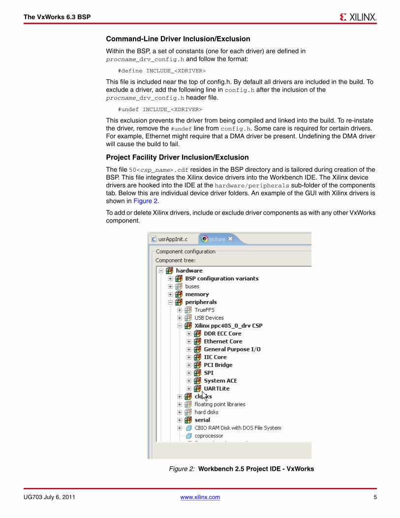
The VxWorks 6.3 BSP
Command-Line Driver Inclusion/Exclusion
Within the BSP, a set of constants (one for each driver) are defined in procname_drv_config.h and follow the format:
#define INCLUDE_<XDRIVER>
This file is included near the top of config.h. By default all drivers are included in the build. To exclude a driver, add the following line in config.h after the inclusion of the procname_drv_config.h header file.
#undef INCLUDE_<XDRIVER>
This exclusion prevents the driver from being compiled and linked into the build. To re-instate the driver, remove the #undef line from config.h. Some care is required for certain drivers. For example, Ethernet might require that a DMA driver be present. Undefining the DMA driver will cause the build to fail.
Project Facility Driver Inclusion/Exclusion
The file 50<csp_name>.cdf resides in the BSP directory and is tailored during creation of the BSP. This file integrates the Xilinx device drivers into the Workbench IDE. The Xilinx device drivers are hooked into the IDE at the hardware/peripherals sub-folder of the components tab. Below this are individual device driver folders. An example of the GUI with Xilinx drivers is shown in Figure 2.
To add or delete Xilinx drivers, include or exclude driver components as with any other VxWorks component.
Figure 2: Workbench 2.5 Project IDE - VxWorks
UG703 July 6, 2011 www.xilinx.com 5

The VxWorks 6.3 BSP
Note: Whatever configuration specified in procname_drv_config.h and config.h is overridden by the project facility.
Building VxWorks
The automatically generated BSPs follow the standard Workbench conventions when it comes to creating VxWorks images. Refer to Workbench documentation on how to make a VxWorks image.
Command-Line BSP Build Extensions
The Xilinx drivers are compiled/linked with the same toolchain VxWorks is built with. Minor additions to the Makefile were required to help Workbench find the location of driver source code files.
Project BSP Build Extensions
The number of new files used to integrate the Xilinx device drivers into the Workbench build process can be seen in the bsp_name directory. As stated earlier, these files are automatically created by SDK. The user need only be aware of that the files exist. These files are prefixed with the instance name of the processor.
Device Integration
Devices in the FPGA-based embedded system have varying degrees of integration with the VxWorks operating system. The degree of integration is selectable by the SDK user in the Connected Peripherals dialog box of the Library/OS Parameters tab. Below is a list of currently supported devices and their level of integration.
• One or more UART 16450/16550/Lite devices can be integrated into the VxWorks Serial I/O (SIO) interface. This makes a UART available for file I/O and printf/stdio. Only one UART device can be selected as the console, where standard I/O (stdin, stdout, and stderr) is directed. A UART device, when integrated into the SIO interface, must be capable of generating an interrupt. Reference the sysSerial.c file of the BSP to see details of this integration.
• Ethernet 10/100 MAC, Ethernet Lite 10/100, Gigabit Ethernet MAC, and 10/100/1000 Tri-speed Ethernet MAC devices can be integrated into the VxWorks Enhanced Network Driver (END) interface. This makes the device available to the VxWorks network stack and thus socket-level applications. An Ethernet device, when integrated into the END interface, must be capable of generating interrupts. Reference the configNet.h and sysNet.c files of the BSP to see details of this integration. Also, the user might need to modify the default bootline values in config.h for the Ethernet device to be used as the boot device.
• An Interrupt controller can be connected to the VxWorks intLib exception handling and the PowerPC 405/440 external non-critical interrupt pin. The generated BSP does not currently handle interrupt controller integration for the critical interrupt pin of the PowerPC 405/440, nor does it support direct connection of a single interrupting device (other than the intc) to the processor. However, the user is always able to add manually this integration in the sysInterrupt.c file of the BSP.
• A System ACE™ controller can be connected to VxWorks as a block device, allowing the user to attach a filesystem to the CompactFlash device connected to the System ACE controller. The user must call manually the BSP functions to initialize the System ACE/CompactFlash as a block device and attach it to the DOS operating system. The functions currently available to the user are: sysSystemAceInitFS() and sysSystemAceMount(). A system ACE controller, when integrated into the block device interface, must be capable of generating an interrupt. Reference the file sysSystemAce.c in the BSP for more details. The BSP will mount the compact flash as a DOS FAT disk partition using the Wind River DosFs2.0 add-on.
6 www.xilinx.com UG703 July 6, 2011

The VxWorks 6.3 BSP
For the VxWorks libraries to be included into the image, the following packages must be defined in config.h or by the Project Facility:
- INCLUDE_DOSFS_MAIN
- INCLUDE_DOSFS_FAT
- INCLUDE_DISK_CACHE
- INCLUDE_DISK_PART
- INCLUDE_DOSFS_DIR_FIXED
- INCLUDE_DOSFS_DIR_VFAT
- INCLUDE_XBD_BLK_DEV
- INCLUDE_XBD_PART_LIB
Programmatically, an application can mount the DOS file system using the following API calls:
FILE *fp;
sysSystemAceInitFS();if (sysSystemAceMount("/cf0", 1) != OK){
/* handle error */}
fp = fopen("/cf0/myfile.dat","r");
• A PCI bridge can be initialized and made available to the standard VxWorks PCI driver and configuration functions. The user is required to edit the config.h and sysBusPci.c BSP files to tailor the PCI memory addresses and configuration for their target system. Note that PCI interrupts are not automatically integrated into the BSP.
• A USB device controller can be integrated into the USB peripheral controller interface of the VxWorks BSP components. To test the USB peripheral controller using the existing Mass Storage emulator component of VxWorks, the following changes are to be done in the VxWorks source file usbTargMsLib.c and in the BSP file config.h . These changes are to be done before the VxWorks project is created.
- Modify the MS_BULK_OUT_ENDPOINT_NUM constant value as "2" in usbTargMsLib.c file. This file is located in the WindRiver-Installed-Directory/Vx-Works6.3/target/src/drv/usb/target/ directory.
- After the modification, the VxWorks source is to be compiled at this directory. The compiler command for a PowerPC 440 processor based system is make CPU=PPC32 and for a PowerPC 405 processor based system it is make CPU=PPC405.
- USB MassStorage emulator uses the local memory for the storage area. The user needs to provide a minimum of 4MB space (modify the LOCAL_MEM_SIZE constant value in the config.h file as 0x400000) in the RAM. The MassStorage emulator code emulates a default storage area of 32k.
• All other devices and associated device drivers are not tightly integrated into a VxWorks interface. Instead, they are loosely integrated and access to these devices is available by directly accessing the associated device drivers from the user’s application.
• User cores and associated device drivers, if included in the SDK project, are supported through the BSP generation flow. The user core device drivers will be copied into the BSP in the same way the Xilinx device drivers are copied. This assumes the directory structure of the user core device driver matches the structure of the Xilinx device drivers. The /data and /build sub-directories of the device driver must exist and be formatted in the same way as the Xilinx device drivers. This includes the CDF snippet and xtag files in the /build/vxworks5_4 sub-directory. User device drivers are not automatically integrated into any OS interface (for example SIO), but they are available for direct access by an application.
UG703 July 6, 2011 www.xilinx.com 7

The VxWorks 6.3 BSP
Deviations
The following list summarizes the differences between SDK generated BSPs and traditional BSPs.
• An extra directory structure is added to the root BSP directory to contain the device driver source code files.
• To keep the BSP buildable while maintaining compatibility with the Workbench Project facility, a set of files named procname_drv_driver_version.c populate the BSP directory that simply #include the source code from the driver subdirectory of the BSP.
• The BSP Makefile has been modified so that the compiler can find the driver source code. The Makefile contains more information about this deviation and its implications.
• SystemACE usage could require changes to VxWorks source code files found in the Workbench distribution directory. Refer to “Bootrom with SystemACE as the Boot Device,” page 12.
Limitations
The automatically-generated BSP is a good starting point, but should not be expected to meet all requirement without configuration. Due to the potential complexities of a BSP, the variety of features that can be included in a BSP, and the support necessary for board devices external to the FPGA, the automatically-generated BSP will likely require enhancements. However, the generated BSP is able to compile and contains the necessary device drivers represented in the FPGA-based embedded system. Some of the commonly used devices are also integrated with the operating system. Specific limitations are listed below.
• An interrupt controller connected to the PowerPC 405/440 processor critical interrupt pin is not automatically integrated into VxWorks’ interrupt scheme. Only the external interrupt is currently supported.
• Bus error detection from bus bridges or arbiters is not supported.
• The command-line VxWorks 6.3 BSP defaults to use the GNU compiler. The user must manually change the Makefile to use the DIAB compiler, or specify the DIAB compiler when creating a Workbench project based on the BSP.
• Memory address ranges might need to be tailored in config.h to match specific memory devices and their address ranges.
• PowerPC 405/440 processor caches are disabled by default. You must manually enable caches through the config.h file or the Workbench project menu.
• When SystemACE is setup to download VxWorks images into RAM using JTAG, all boots are cold (no warm boots). This is because the System ACE controller resets the processor whenever it performs an ace file download. An effect of this could cause exception messages generated by VxWorks to not be printed on the console when the system is rebooted due to an exception in an ISR or a kernel panic.
Note: No compressed images can be used with SystemACE. This applies to standard compressed images created with Workbench such as bootrom. Compressed images cannot be placed on SystemACE as an ace file. SystemACE cannot decompress data as it writes it to RAM. Starting such an image will lead to a system crash.
• A command-line build cannot initialize the network when SystemACE is the boot device. This requires that the application provide code to initialize the network when SystemACE is the boot device. To circumvent this issue see the discussion of $WIND_BASE/target/src/config/usrNetwork.c in the “Bootrom with SystemACE as the Boot Device,” page 12.
• On the PowerPC 405/440 processor, the reset vector is at physical address 0xFFFFFFFC. There is a short time window where the processor will attempt to fetch and execute the instruction at this address while SystemACE processes the ace file.
8 www.xilinx.com UG703 July 6, 2011

Booting VxWorks
The processor needs to be given something to do during this time even if it is a spin loop:
FFFFFFFC b .
If block RAM occupies this address range, then the designer who creates the bitstream should place instructions here with the ELF to block RAM utility found in the Xilinx Integrated Software Environment (ISE®) tools.
• VxBus is not supported.
Booting VxWorks
VxWorks Bootup Sequence
There are many variations of VxWorks images with some based in RAM, some in ROM. Depending on board design, not all these images are supported. The following list discusses various image types:
• ROM compressed images - These images begin execution in ROM and decompress the BSP image into RAM, then transfer control to the decompressed image in RAM. This image type is not compatible with SystemACE because SystemACE doesn’t know the image is compressed and will dutifully place it in RAM at an address that will be overwritten by the decompression algorithm when it begins. It may be possible to get this type of image to work if modifications are made to the standard Workbench makefiles to handle this scenario.
• RAM based images - These images are loaded into RAM by a bootloader, SystemACE, or an emulator. These images are fully supported.
• ROM based images - These images begin execution in ROM, copy themselves to RAM then transfer execution to RAM. In designs with SystemACE as the bootloader, the image is automatically copied to RAM. The hand-coded BSP examples short-circuit the VxWorks copy operation so that the copy does not occur again after control is transferred to RAM by SystemACE (see romInit.s).
• ROM resident images - These images begin execution in ROM, copy the data section to RAM, and execution remains in ROM. In systems with only a SystemACE, this image is not supported. Theoretically block RAM could be used as a ROM, however, the current FPGAs being used in the evaluation boards may not have the capacity to store a VxWorks image which could range in size from 200KB to over 700KB.
VxWorks Boot Sequence
This standard image is designed to be downloaded to the target RAM space by some device. Once downloaded, the processor is setup to begin execution at function _sysInit at address RAM_LOW_ADRS. (this constant is defined in config.h and Makefile). Most of the time, the device performing the download will do this automatically as it can extract the entry point from the image.
1. _sysInit : This assembly language function running out of RAM performs low level initialization. When completed, this function will setup the initial stack and invoke the first C function usrInit(). The _sysInit is located in source code file <bspname>/sysALib.s.
2. usrInit() : This C function running out of RAM sets up the C runtime environment and performs pre-kernel initialization. It invokes sysHwInit() (implemented in sysLib.c) to place the HW in a quiescent state. When completed, this function will call kernelInit() to bring up the VxWorks kernel. This function will in turn invoke usrRoot() as the first task.
3. usrRoot() : Performs post-kernel initialization. Hooks up the system clock, initializes the TCP/IP stack, etc. It invokes sysHwInit2() (implemented in sysLib.c) to attach and enable HW interrupts. When complete, usrRoot() invokes user application startup code usrAppInit() if so configured in the BSP.
Both usrInit() and usrRoot() are implemented by Wind River. The source code files they exist in are different depending on whether the command line or the Workbench Project facility
UG703 July 6, 2011 www.xilinx.com 9

Booting VxWorks
is being used to compile the system. Under the command line interface, they are implemented at $WIND_BASE/target/config/all/usrConfig.c. Under the project facility, they are maintained in the project directory.
"bootrom_uncmp" Boot Sequence
This standard image is ROM based but in reality it is linked to execute out of RAM addresses. While executing from ROM, this image uses relative addressing tricks to call functions for processing tasks before jumping to RAM.
1. Power on. Processor vectors to 0xFFFFFFFC where a jump instruction should be located that transfers control to the bootrom at address _romInit.
2. _romInit : This assembly language function running out of ROM notes that this is a cold boot then jumps to start. Both _romInit and start are located in source code file bspname/romInit.s.
3. start : This assembly language function running out of ROM sets up the processor, invalidates the caches, and prepares the system to operate out of RAM. The last operation is to invoke C function romStart() which is implemented by Wind River and is located in source code file $WIND_BASE/target/config/ all/bootInit.c.
4. romStart() : This C function running out of ROM copies VxWorks to its RAM start address located at RAM_HIGH_ADRS (this constant is defined in config.h and Makefile). After copying VxWorks, control is transferred to function usrInit() in RAM.
5. Follows steps 2 and 3 of the “VxWorks Boot Sequence”.
"bootrom_uncmp" Boot Sequence with SystemACE
This non-standard image is similar to the image discussed in the previous section except that SystemACE is used to load it. Several changes have to be made to the boot process. More information can be found in section “Bootrom with SystemACE as the Boot Device,” page 12.
1. Power on. SystemACE loads the image into RAM at RAM_HIGH_ADRS (this constant is defined in config.h and Makefile) and sets the processor to begin fetching instructions at address _romInit.
2. _romInit : This assembly language function running out of RAM notes that this is a cold boot then jumps to start. Both _romInit and start are located in source code file <bspname>/romInit.s.
3. start : This assembly language function running out of RAM simply jumps to function _sysInit. The call to romStart() is bypassed because SystemACE has already loaded the bootrom into it’s destination RAM address.
Follow steps 1, 2, and 3 of the “VxWorks Boot Sequence,” page 9.
Bootroms
The bootrom is a scaled down VxWorks image that operates in much the same way a PC BIOS. Its primary function is to find and boot a full VxWorks image. The full VxWorks image can reside on disk, in flash memory, or on some host using the Ethernet. The bootrom must be compiled in such a way that it has the ability to retrieve the image. If the image is retrieved from an Ethernet network, then the bootrom must have the TCP/IP stack compiled in, if the image is on disk, then the bootrom must have disk access support compiled in, and so forth. The bootroms do little else than retrieve and start the full image and maintain a bootline. The bootline is a text string that sets certain user characteristics such as the IP address target when using Ethernet and the file path to the VxWorks image to boot.
Bootroms are not a requirement. They are typically used in a development environment then replaced with a production VxWorks image.
10 www.xilinx.com UG703 July 6, 2011

Booting VxWorks
Creating Bootroms
At a command shell in the BSP directory, issue the following command to create an uncompressed bootrom image (required for SystemACE):
make bootrom_uncmp
or
make bootrom
to create a compressed image suitable for placing in a flash memory array.
Bootrom Display
Upon cycling power, if the bootroms are working correctly, output similar to the following should be seen on the console serial port:
VxWorks System Boot
Copyright 1984-2006 Wind River Systems, Inc.
CPU: ppc405_0 VirtexII Pro PPC405 Version: VxWorks 6.3BSP version: 1.2/0Creation date: Aug 11, 2006, 16:40:32
Press any key to stop auto-boot... 3
[VxWorks Boot]:
Typing help at this prompt lists the available commands.
Bootline
The bootline is a text string that defines user serviceable characteristics such as the IP address of the target board and how to find a VxWorks image to boot. The bootline is maintained at runtime by the bootrom and is typically kept in some non-volatile (NVRAM) storage area of the system such as an EEPROM or flash memory. If there is no NVRAM, or an error occurs reading it, then the bootline is hard-coded with DEFAULT_BOOT_LINE defined in the config.h source code file of the BSP. In new systems where NVRAM has not been initialized, the bootline may be undefined data.
The bootline can be changed if the auto-boot countdown sequence is interrupted by entering a character on the console serial port. The c command can then be used to interactively edit the bootline. Enter p to view the bootline. On a non-bootrom image, the bootline can be changed by entering the bootChange command at a host or target shell prompt.
The bootline fields are defined below:
• boot device : Device from which to boot. This could be ethernet, or a local disk.
• When changing the bootline, the unit number can be shown appended to this field (xemac0 or sysace=10) when prompting for the new boot device. This number can be ignored.
• processor number : Always 0 with single processor systems.
• host name : Name as needed.
• file name : The VxWorks image to boot.
• inet on ethernet (e) : The IP internet address of the target. If there is no network interface, then this field can be left blank.
UG703 July 6, 2011 www.xilinx.com 11

Booting VxWorks
• host inet (h) : The IP internet address of the host. If there is no network interface, then this field can be left blank.
• user (u) : User name for host file system access. Pick whatever name suites you. Your FTP server must be setup to allow this user access to the host file system.
• ftp password (pw) : Password of your choice for host file system access. Your FTP server must be setup to allow this user access to the host file system.
• flags (f) : For a list of options, enter the help command at the [VxWorks Boot]: prompt.
• target name (tn) : Name as needed. Set according to network requirements.
• other (o) : This field is useful when you have a non-ethernet device as the boot device. When this is the case, VxWorks will not start the network when it boots. Specifying an ethernet device here will enable that device at boot time with the network parameters specified in the other bootline fields.
• inet on backplane (b) : Typically left blank if the target system is not on a VME or PCI backplane.
• gateway inet (g) : Enter an IP address here if you have to go through a gateway to reach the host computer. Otherwise leave blank.
• startup script (s) : Path to a file on the host computer containing shell commands to execute once bootup is complete. Leave blank if not using a script. Examples are:
- SystemACE resident script: /cf0/vxworks/scripts/myscript.txt
- Host resident script: c:/temp/myscript.txt
Bootrom with SystemACE as the Boot Device
SystemACE enabled bootroms are capable of booting VxWorks images directly off the Compact Flash device either as a regular elf file or an ace file.
Required Modifications to VxWorks Source
While the SDK is capable of generating a BSP that uses SystemACE in a VxWorks image that can open and close files in a DOS filesystem, it cannot generate a BSP that uses SystemACE as a bootrom boot device. To use SystemACE in this way requires extensive modifications to bootrom code provided by Wind River. Wind River allows BSP developers to change Workbench source code files provided they keep the changes local to the BSP and leave the original code as is. The two files that have to be modified from their original version are:
1. $WIND_BASE/target/config/all/bootConfig.c: This file is overridden with one found in the bspname directory. The changes needed are to add code to properly parse the bootline and to initialize and use SystemACE as a JTAG and DOS boot device. To override the default bootConfig.c, the following line must be added to the Makefile for the BSP:
BOOTCONFIG = ./bootConfig.c.
2. $WIND_BASE/target/config/comps/src/net/usrNetBoot.c: This file is overridden with one found in the bspname/net/usrNetBoot.c directory. The changes needed are to add code to make VxWorks aware that SystemACE is a disk based system like IDE, SCSI, or floppy drives. This change allows a BSP built from the Workbench Project downloaded with a SystemACE enabled bootrom to properly process the other field of the bootline. The existence of the modified file in the BSP directory automatically overrides the original.
Neither of these files are provided by the SDK because they are maintained in their original form by Wind River.
A third file, $WIND_BASE/target/src/config/usrNetwork.c, cannot be overridden because of the architecture of the command line BSP build process. This affects network capable BSPs built from the command line that are downloaded with a SystemACE enabled bootrom. Without modifying usrNetwork.c, affected BSPs are unable to initialize their network device and must rely on application code to perform this function.
12 www.xilinx.com UG703 July 6, 2011

Booting VxWorks
If the user desires, they can make the change to this file in their Workbench installation. There are disadvantages to this approach because any edits made to this file affect all users of that installation and may be lost if the user upgrades or re-installs Workbench. The change to usrNetwork.c occurs in function usrNetDevStart().
from:
if ((strncmp (params.bootDev, "scsi", 4) == 0) || (strncmp (params.bootDev, "ide", 3) == 0) || (strncmp (params.bootDev, "ata", 3) == 0) || (strncmp (params.bootDev, "fd", 2) == 0) || (strncmp (params.bootDev, "tffs", 4) == 0))
to
if ((strncmp (params.bootDev, "scsi", 4) == 0) || (strncmp (params.bootDev, "ide", 3) == 0) || (strncmp (params.bootDev, "ata", 3) == 0) || (strncmp (params.bootDev, "fd", 2) == 0) || (strncmp (params.bootDev, "sysace", 6) == 0) || (strncmp (params.bootDev, "tffs", 4) == 0))
Note: Edit this code at your own risk.
Special Configuration
Preparing a bootrom_uncmp image downloadable by SystemACE as an ace file requires special configuration. These changes are required because the bootrom is linked to begin running out of a non-volatile memory device, copy itself to RAM, then transfer control to the RAM copy. The changes will prevent the copy operation since SystemACE has already place the bootrom into a RAM device at reset.
a. Change the definitions of ROM_TEXT_ADRS and ROM_WARM_ADRS to a value equivalent to RAM_HIGH_ADRS in both config.h and Makefile.
b. Change the assembly language code at the start label in romInit.s to jump to function _sysInit:
start: LOADPTR (r1, _sysInit) mtlr r1
blrl
Bootline Format
The boot device field 6_3 of the bootline is specified using the following syntax:
sysace=partition number
where partition number is the partition from which to boot. Normally, this value is set to 1, but some compact flash devices do not have a partition table and are formatted as if they were a large floppy disk. In this case, specify 0 as the partition number. Failure to get the partition number correct will lead to errors being reported by the VxWorks dosFS libraries when the drive is mounted.
UG703 July 6, 2011 www.xilinx.com 13

Booting VxWorks
The file name field of the bootline is set depending on how the System ACE is to boot the system. There are two boot methods:
1. Boot from a regular file. This is similar to network booting in that the vxWorks image resides in the SystemACE compact flash storage device instead of the host file system. The compact flash device is a DOS FAT file system partition. Build vxWorks using the Workbench tools, copy the resulting image file to the compact flash device using a USB card reader or similar tool, then specify that file in the file name field of the boot ROM. The file name must have the following syntax:
cf0/path to vxWorks image
where:
- cf0 is the mount point
- The path to vxWorks image provides the complete path to the VxWorks image to boot. When being specified in this way, the bootrom will mount the drive as a FAT formatted disk, load the file into memory and begin execution.
2. Boot from an ace file. The ace file can contain HW only, SW only, or HW + SW. When booting from an ace file with HW, the FPGA is reprogrammed. If the ace file contains SW, then it is loaded into the memory, the PC of the processor is set to the entry point and released to begin fetching instructions. This boot method is flexible in that a totally different HW profile can be booted from a VxWorks bootrom. The file name must have the following syntax:
cfgaddr[x]
where [X] is a number between 0 and 7 that corresponds to one of the configuration directories specified in the XILINX.SYS file resident in the root directory of the compact flash device. If [X] is omitted, then the default configuration is used. The default configuration is typically selected by a rotary switch mounted somewhere on the evaluation board. The bootrom will trigger a JTAG download of the ace file pointed to by the specified config address. There should be only a single file with an .ace extension in the selected configuration directory.
In either boot scenario, if the ethernet device is to be started when the downloaded VxWorks starts, the "other" field of the bootline must be modified to contain the name of the network device.
Bootrom with 10/100 Ethernet (EMAC) as the Boot Device
SDK will generate a BSP that is capable of being built as a bootrom using the EMAC as a boot device. Very little user configuration is required. The MAC address is hard coded in the source file sysNet.c. The BSP can be used with the default MAC as long as the target is on a private network and there is no more than one target on that network with the same default MAC address. Otherwise the designer should replace this MAC with a function to retrieve one from a non-volatile memory device on their target board.
To specify the EMAC as the boot device in the bootrom, change the boot device field in the bootline to xemac. If there is a single EMAC, set the unit number to 0.
Bootrom with 1 Gigabit Ethernet (GEMAC) as the Boot Device
SDK will generate a BSP that is capable of being built as a bootrom using the GEMAC as a boot device. Very little user configuration is required. The MAC address is hard coded in the source file sysNet.c. The BSP can be used with the default MAC as long as the target is on a private network and there is no more than one target on that network with the same default MAC address. Otherwise the designer should replace this MAC with a function to retrieve one from a non-volatile memory device on their target board.
To specify the GEMAC as the boot device in the bootrom, change the boot device field in the bootline to xgemac. If there is a single GEMAC, set the unit number to 0.
14 www.xilinx.com UG703 July 6, 2011

Booting VxWorks
Bootline Examples
The following example boots from the ethernet using the Xilinx xemac as the boot device. The image booted is on the host file system on drive C.
boot device : xemacunit number : 0processor number : 0host name : hostfile name : c:/WindRiver/vxworks-6.3/target/config/ml507/vxWorksinet on ethernet (e) : 192.168.0.2host inet (h) : 192.168.0.1user (u) : xemhostftp password (pw) : whateverflags (f) : 0x0target name (tn) : vxtargetother (o) :
The following example boots from a file resident on the first partition of the compact Flash device for the SystemACE. If the file booted from /cf0/vxworks/images/vxWorks uses the network, then the xemac device is initialized.
boot device : sysace=1unit number : 0processor number : 0host name : hostfile name : /cf0/vxworks/images/vxWorksinet on ethernet (e) : 192.168.0.2host inet (h) : 192.168.0.1user (u) : xemhostftp password (pw) : whateverflags (f) : 0x0target name (tn) : vxtargetother (o) : xemac
The following example boots from an ace file resident on the first partition of the SystemACE compact flash device. The location of the ace file is set by XILINX.SYS located in the root directory of the compact flash device. If the ace file contains a VxWorks SW image that uses the network, then the xemac device is initialized for that image.
boot device : sysace=1unit number : 0processor number : 0host name : hostfile name : cfgaddr2inet on ethernet (e) : 192.168.0.2host inet (h) : 192.168.0.1user (u) : xemhostftp password (pw) : whateverflags (f) : 0x0target name (tn) : vxtargetother (o) : xemac
UG703 July 6, 2011 www.xilinx.com 15

Booting VxWorks
Caches
The instruction and data caches are managed by VxWorks proprietary libraries. They are enabled by modifying the following constants in config.h or by using the Workbench Project facility to change the constants of the same name:
• INCLUDE_CACHE_SUPPORT: If defined, the VxWorks cache libraries are linked into the image. If caching is not desired, then #undef this constant.
• USER_I_CACHE_ENABLE: If defined, VxWorks will enable the instruction cache at boot time. Requires INCLUDE_CACHE_SUPPORT be defined to have any effect.
• USER_D_CACHE_ENABLE: If defined, VxWorks enables the data cache at boot time. Requires INCLUDE_CACHE_SUPPORT be defined to have any effect.
MMU
If the MMU is enabled, then the cache control discussed in the previous section may not have any effect. The MMU is managed by VxWorks proprietary libraries but the initial setup is defined in the BSP. To enable the MMU, the constant INCLUDE_MMU_BASIC should be defined in config.h or by using the Project Facility. The constant USER_D_MMU_ENABLE and USER_I_MMU_ENABLE control whether the instruction and/or data MMU is utilized.
VxWorks initializes the MMU based on data in the sysPhysMemDesc structure defined in sysCache.c. User-reserved memory and ED&R (when INCLUDE_EDR_PM is enabled) reserved memory is included in this table. Amongst other things, this table configures memory areas with the following attributes:
• Whether instruction execution is allowed
• Whether data writes are allowed
• Instruction and data cacheability attributes
• Translation offsets used to form virtual addresses.
When VxWorks initializes the MMU, it takes the definitions from sysPhysMemDesc and creates page table entries (PTEs) in RAM. Each PTE describes 4KB of memory area (even though the processor is capable of representing up to 16MB per PTE) Beware that specifying large areas of memory uses substantial amounts of RAM to store the PTEs. To map 4MB of contiguous memory space takes 8KB of RAM to store the PTEs.
To increase performance with the VxWorks basic MMU package for the PowerPC 405/440 processor, it might be beneficial to not enable the instruction MMU and rely on the cache control settings in the ICCR register. This strategy can dramatically reduce the number of page faults while still keeping instructions in cache. The initial setting of the ICCR is defined in the bspname.h header file.
Without the MMU enabled, the following rules apply to configuring memory access attributes and caching:
• There is no address translation, all effective addresses are physical.
• Cache control granularity is 128MB.
• The guarded attribute applies only to speculative instruction fetches on the PowerPC 405 processor.
FPU
Hard floating-point unit(FPU) is supported for PowerPC 440 processor systems. To enable hard floating-point unit, select diab or gnu in generated BSP Makefile TOOLS. To disable hard floating-point unit, select sfdiab or sfgnu in Makefile’s make variable TOOLS.
16 www.xilinx.com UG703 July 6, 2011

Overview One of the key embedded system development activities is the development of the BSP. The creation of a BSP can be a lengthy process that must be incurred when there is a change in the microprocessor complex which is comprised of the processor and associated peripherals. Although the management of these changes applies to any microprocessor-based project, now the changes can be accomplished more rapidly with the advent of programmable System-on-Chip (SoC) hardware.
This document describes automatic generation of a customized VxWorks 6.5 BSP for the IBM PowerPC® 405/440 microprocessor and its peripherals as defined within a Xilinx® FPGA. An automatically generated BSP enables embedded system designers to:
• Decrease the development cycles, thereby decreasing the time-to-market
• Create a customized BSP to match the hardware and the application
• Eliminate BSP design bugs (automatically created based on certified components)
• Enable application software development by eliminating the wait for BSP development
The VxWorks 6.5 BSP is generated from Software Development Kit (SDK), an IDE delivered as part of the Xilinx Embedded Development Kit (EDK) or available separately from Xilinx. SDK is used to create software applications for embedded systems within Xilinx FPGAs. The VxWorks BSP contains all the necessary support software for a system, including boot code, device drivers, and RTOS initialization. The BSP is customized based on the peripherals chosen and configured by the user for the FPGA-based embedded system.
Experienced BSP designers should readily integrate a generated BSP into their target system. Conversely, less experience users might encounter difficulties because, even though SDK can generate an operational BSP for a given set of IP hardware, there is always some additional configuration and adjustments required to produce the best performance out of the target system. It is recommended that the user have available the Wind River VxWorks BSP Developer’s Guide and the VxWorks Application Programmer’s Guide or consider the Wind River classes on BSP design, available at an additional cost.
Requirements
The Wind River Workbench 2.6.1 development kit must be installed on the host computer. Because SDK generates re-locatable BSPs that are compiled and configured outside the SDK environment, the host computer need not have both the Xilinx SDK and Workbench installed.
Microprocessor Library Definition
SDK supports a plug-in interface for 3rd party libraries and operating systems through the Microprocessor Library Definition (MLD) interface, thereby allowing 3rd party vendors to have their software available to SDK users. In addition, it provides the vendors a means for tailoring their libraries or BSPs to the FPGA-based embedded system created within Xilinx tools. Because the system can change easily, this capability is critical in properly supporting embedded systems in FPGAs.
Xilinx develops and maintains the VxWorks 6.5 MLD in its SDK releases. The MLD is used to automatically generate the VxWorks 6.5 BSP.
UG704 July 6, 2011
Automatic Generation of Wind River VxWorks 6.5 Board Support Packages
UG704 July 6, 2011 www.xilinx.com 1
© 2011 Xilinx, Inc. XILINX, the Xilinx logo, Virtex, Spartan, ISE, and other designated brands included herein are trademarks of Xilinx in the United States and other countries. All other trademarks are the property of their respective owners.

Generating the VxWorks 6.5 BSP
Template-Based Approach
A set of VxWorks 6.5 BSP template files are released with the SDK. These template files are used during automatic generation of the BSP and appropriate modifications are made based on the makeup of the FPGA-based embedded system.
These template files could be used as a reference for building a BSP from scratch if the user chooses not to automatically generate a BSP.
Device Drivers
A set of device driver source files are released with the SDK and reside in an installation directory. During creation of a customized BSP, device driver source code is copied from this installation directory to the BSP directory. Only the source code pertaining to the devices built into the FPGA-based embedded system are copied. This copy provides the user with a self-contained, standalone BSP directory which can be modified or relocated. If the user makes changes to the device driver source code for this BSP, then later wishes to undo the changes, the SDK tool can be used to regenerate the BSP. At that point, the device driver source files are recopied from the installation directory to the BSP.
Generating the VxWorks 6.5 BSP
Using SDK
SDK is available as a separately installed tool or within the EDK and is a software development environment for developing embedded software around the PowerPC® 405/440 processors or the MicroBlaze™ processor-based embedded systems. This section describes the steps needed to create a VxWorks 6.5 BSP using SDK. These steps are applicable when using Xilinx tools of release 11.1 and forward.
It is assumed that a valid hardware design has been created and exported to SDK, and SDK has been opened and pointed to the hardware design.
1. Using File > New, create a new Board Support Package project. In the dialog box, enter a project name, and select vxworks6_5 as the Board Support Package Type. Note that SDK can manage multiple projects of different BSP types.
The remaining steps pertain to the Tools > Board Support Package Settings dialog box, which should automatically be displayed after step 1.
2 www.xilinx.com UG704 July 6, 2011

Generating the VxWorks 6.5 BSP
Figure 1, page 3 shows the board support package settings.
Figure 1: Board Support Package Settings
2. Configure the VxWorks console device.
If a serial device such as a Uart is intended to be used as the VxWorks console, select or enter the instance name of the serial device as the STDIN/STDOUT peripheral in the Board Support Package Settings dialog box. It is important to enter the same device for both STDIN and STDOUT. Currently, only the Uart 16550/16450 and UartLite devices are supported as VxWorks console devices.
3. Integrate the device drivers.
a. Connect to VxWorks
There is a connected_periphs dialog box available in the Board Support Package Settings dialog box. Peripherals have been pre-populated for user convenience. Use this dialog box to modify those peripherals to be tightly integrated with the OS, including the device that was selected as the STDIN/STDOUT peripheral. See “Device Integration,” page 8 for more details on device integration.
b. Memory Size
This field is used to configure the BSP to match the actual hardware memory size on your board.
c. Uart16550_baud_rate
This field is used to input the baud rate for projects with the UART 16550/16450 core. It is not necessary to enter a value here for projects with the UART Lite core since the baud rate is set for a UART Lite at hardware build time.
UG704 July 6, 2011 www.xilinx.com 3

Generating the VxWorks 6.5 BSP
d. RAM_INSTANCE
This is a drop down menu to select the peripheral instance that is to be used as RAM in BSP. The subfields memory bank and the base address of RAM under RAM_INSTANCE are to be configured to match the actual hardware settings.
e. ROM_INSTANCE
This is a drop down menu to select the peripheral instance that is to be used as ROM in BSP. FLASH is the only ROM device supported on the Xilinx Evaluation boards. If there is no ROM in the system, the user can leave the default setting i.e. none. If there is a FLASH in the system the subfields memory bank and the base address of ROM under ROM_INSTANCE are to be configured to match the actual hardware settings.
f. RAM_LOW_ADRS_OFFSET
This field is used to input the address offset for the RAM base address to obtain the RAM address for vxWorks used in the BSP and is to be configured to match the hardware system settings.
g. RAM_HIGH_ADRS_OFFSET
This field is used to input the address offset for the RAM base address to obtain the RAM address used in the BSP for boot ROM and is to be configured to match the hardware system settings.
h. ROM_LOW_ADRS_OFFSET
This field is used to input the address offset for the ROM base address to obtain the FLASH start address used in the BSP and is to be configured to match the hardware system settings.
i. ROM_HIGH_ADRS_OFFSET
This field is used to input the address offset for the ROM base address to obtain the FLASH end address used in the BSP and is to be configured to match the hardware system settings.
j. ROM_SIZE
This field is used to configure the BSP and should match the actual hardware system settings.
k. ROM_TEXT_ADRS_OFFSET
This field is used to input the address offset for the ROM base address to obtain the text section start address used in the BSP and is to be configured to match the hardware system settings.
l. ROM_WARM_ADRS_OFFSET
This field is used to input the address offset for the ROM base address to obtain the warm reboot entry address used in the BSP and is to be configured to match the hardware system settings.
4. Generate the VxWorks 6.5 BSP
Click OK on the Board Support Package Settings dialog box to generate the BSP. The output of this invocation is shown in the SDK console window. After completion, the resulting VxWorks 6.5 BSP exists in your SDK workspace, under the project directory name you created in step 1 under the PowerPC 405/440 instance subdirectory. For example, if in the hardware design the user has named the PowerPC 405 instance, myppc405, the BSP resides at <SDK workspace>/<SDK project name>/myppc405/bsp_ppc405.
4 www.xilinx.com UG704 July 6, 2011

The VxWorks 6.5 BSP
Backups
To prevent the inadvertent loss of changes to BSP source files, existing files in the directory location of the BSP are copied into a backup directory before being overwritten. The backup directory resides within the BSP directory and is named backup<timestamp>, where <timestamp> represents the current date and time. Because the BSP that is generated by SDK is relocatable, it is recommended to relocate the BSP from the SDK project directory to an appropriate BSP development directory as soon as the hardware platform is stable.
The VxWorks 6.5 BSP
This section describes the VxWorks 6.5 BSP output by SDK. It is assumed that the reader is familiar with Wind River’s Workbench 2.6.1 IDE.
The automatically generated BSP is integrated into the Workbench IDE. The BSP can be compiled from the command-line using the Workbench make tools, or from the Workbench Project facility (also referred to as the Workbench IDE).
After the BSP is generated, type make vxWorks from the command-line to compile a bootable RAM image. This assumes the Workbench environment has been previously set up, which can be done on the command-line using the wrenv Wind River environment utility on a Windows platform. See the Wind River Workbench Command-Line Users Guide: Creating a Development Shell With wrenv for more information on using the command-line utilities. If using the Workbench Project facility, you can create a project based on the newly generated BSP, then use the build environment provided through the IDE to compile the BSP.
In Workbench 2.6.1, the diab compiler is supported in addition to the gnu compiler. The VxWorks 6.5 BSP created by SDK has a Makefile that can be modified on the command-line to use the diab compiler instead of the gnu compiler. Look for the make variable named TOOLS and set the value to sfdiab instead of sfgnu. For PowerPC 440 processors with hard floating-point unit (FPU) systems, select diab or gnu. If using the Workbench Project facility, select the desired tool when the project is first created.
Driver Organization
This section briefly discusses how the Xilinx drivers are compiled and linked and eventually used by Workbench makefiles to be included into the VxWorks image.
Xilinx drivers are implemented in C programming language and can be distributed among several source files unlike traditional VxWorks drivers, which consist of single C header and implementation files.
There are up to three components for Xilinx drivers:
• Driver source inclusion
• OS independent implementation
• OS dependent implementation (optional)
Driver source inclusion refers to how Xilinx drivers are compiled. For every driver, there is a file named <procname>_drv_<dev>_<version>.c. Using the #include command ncludes the source file(s) (*.c) for each driver for each given device.
This process is analogous to how the VxWorks sysLib.c # include’s source for Wind River supplied drivers. Xilinx files are not included in sysLib.c, as are the rest of the drivers, because of namespace conflicts and maintainability issues. If all Xilinx files were part of a single compilation unit, static functions and data are no longer private. This places restrictions on the device drivers and would negate their operating system independence.
The OS independent part of the driver is designed for use with any operating system or any processor. It provides an API that uses the functionality of the underlying hardware. The OS dependent part of the driver adapts the driver for use with VxWorks.
UG704 July 6, 2011 www.xilinx.com 5

The VxWorks 6.5 BSP
Such examples are SIO drivers for serial ports, or END drivers for ethernet adapters. Not all drivers require the OS dependent drivers, nor is it required to include the OS dependent portion of the driver in the VxWorks build.
Device Driver Location
The automatically generated BSP resembles most other Workbench BSPs except for the placement of device driver code. Off-the-shelf device driver code distributed with the Workbench IDE typically resides in the vxworks-6.5/target/src/drv directory in the Workbench installation directory. Device driver code for a BSP that is automatically generated resides in the BSP directory itself. This minor deviation is due to the dynamic nature of FPGA-based embedded system. Since the FPGA-based embedded system can be reprogrammed with new or changed IP, the device driver configuration can change, calling for a more dynamic placement of device driver source files.
The directory tree for the automatically generated BSP is <bsp_name>/<csp_name>_csp/xsrc.
The top-level directory is named according to the name of the processor instance in the hardware design project. The customized BSP source files reside in this directory. There is a subdirectory within the BSP directory named according to the processor instance with _drv_csp as a suffix. The driver directory contains two subdirectories. The xsrc subdirectory contains all the device driver related source files. If building from the Workbench Project facility, the files generated during the build process reside at $PRJ_DIR/$BUILD_SPEC.
Configuration
BSPs generated by SDK are configured like any other VxWorks 6.5 BSP. There is little configurability to Xilinx drivers because the IP hardware has been pre-configured in most cases. The only configuration available generally is whether the driver is included in the VxWorks build at all. The process of including/excluding drivers depends on whether the Project facility or the command-line method is being used to perform the configuration activities.
Note that simply by including a Xilinx device driver does not mean that the driver will be automatically utilized. Most drivers with VxWorks adapters have initialization code. In some cases the user may be required to add the proper driver initialization function calls to the BSP.
When using SDK to generate a BSP, the resulting BSP files may contain “TODO” comments. These comments, many of which originate from the PowerPC 405/440 BSP template provided by Wind River, provides suggestions what the user must provide to configure the BSP for the target board. The VxWorks BSP Developer Guide and VxWorks Application Programmer’s Guide are very useful resources for BSP configuration.
Command-Line Driver Inclusion/Exclusion
Within the BSP, a set of constants (one for each driver) are defined in <procname>_drv_config.h and follow the format:
#define INCLUDE_<XDRIVER>
This file is included near the top of config.h. By default all drivers are included in the build. To exclude a driver, add the following line in config.h after the inclusion of the <procname>_drv_config.h header file.
#undef INCLUDE_<XDRIVER>
This exclusion prevents the driver from being compiled and linked into the build. To re-instate the driver, remove the #undef line from config.h. Some care is required for certain drivers. For example, Ethernet might require that a DMA driver be present. Undefining the DMA driver causes the build to fail.
6 www.xilinx.com UG704 July 6, 2011
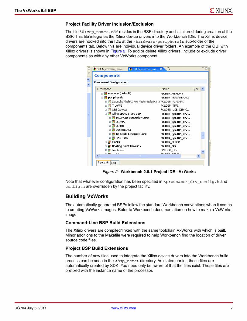
The VxWorks 6.5 BSP
Project Facility Driver Inclusion/Exclusion
The file 50<csp_name>.cdf resides in the BSP directory and is tailored during creation of the BSP. This file integrates the Xilinx device drivers into the Workbench IDE. The Xilinx device drivers are hooked into the IDE at the /hardware/peripherals sub-folder of the components tab. Below this are individual device driver folders. An example of the GUI with Xilinx drivers is shown in Figure 2. To add or delete Xilinx drivers, include or exclude driver components as with any other VxWorks component.
Note that whatever configuration has been specified in <procname>_drv_config.h and config.h are overridden by the project facility.
Building VxWorks
The automatically generated BSPs follow the standard Workbench conventions when it comes to creating VxWorks images. Refer to Workbench documentation on how to make a VxWorks image.
Command-Line BSP Build Extensions
The Xilinx drivers are compiled/linked with the same toolchain VxWorks with which is built. Minor additions to the Makefile were required to help Workbench find the location of driver source code files.
Project BSP Build Extensions
The number of new files used to integrate the Xilinx device drivers into the Workbench build process can be seen in the <bsp_name> directory. As stated earlier, these files are automatically created by SDK. You need only be aware of that the files exist. These files are prefixed with the instance name of the processor.
Figure 2: Workbench 2.6.1 Project IDE - VxWorks
UG704 July 6, 2011 www.xilinx.com 7

The VxWorks 6.5 BSP
Device Integration
Devices in the FPGA-based embedded system have varying degrees of integration with the VxWorks operating system. The degree of integration is selectable by the SDK user in the Connected Peripherals dialog box of the Library/OS Parameters tab. Below is a list of currently supported devices and their level of integration.
• VxBus device driver model is supported starting from vxWorks6.5 BSP. Reference the sysLib.c and hwconf.c of the BSP to see details of this migration.
• One or two UART 16450/16550/Lite devices can be integrated into the VxWorks Serial I/O (SIO) interface. This makes a UART available for file I/O and printf/stdio. Only one UART device can be selected as the console, where standard I/O (stdin, stdout, and stderr) is directed. A UART device, when integrated into the SIO interface, must be capable of generating an interrupt. If you want more than two UART device in your BSP, the ppc405_0.h/ppc440_0.h file must be manually modified to change the number of SIO devices to match.
• Ethernet Lite 10/100 and 10/100/1000 Local Link Tri-speed Ethernet MAC devices can be integrated into the VxWorks Enhanced Network Driver (END) interface. This makes the device available to the VxWorks network stack and thus socket-level applications. An Ethernet device, when integrated into the END interface, must be capable of generating interrupts. You might need to modify the default bootline values in the config.h for the Ethernet device to be used as the boot device.
• An Interrupt controller can be connected to the VxWorks intLib exception handling and the PowerPC 405/440 external non-critical interrupt pin. The generated BSP does not currently handle interrupt controller integration for the critical interrupt pin of the PowerPC 405/440 processor, nor does it support direct connection of a single interrupting device (other than the intc) to the processor. However, the user is always able to add manually this integration in the sysInterrupt.c file of the BSP.
• A System ACE™ controller can be connected to VxWorks as a block device, allowing the user to attach a filesystem to the CompactFlash device connected to the System ACE controller. You must manually call the BSP functions to initialize the System ACE/CompactFlash as a block device and attach it to the DOS operating system. The function currently available to the user is sysSystemAceMount(). A system ACE controller, when integrated into the block device interface, must be capable of generating an interrupt. Reference the xsysaceblkadapter.c file in the BSP for more details. The BSP mounts the CF as a DOS FAT disk partition using the Wind River DosFs2.0 add-on.
To get the required VxWorks libraries into the image, the following packages must be defined in config.h or by the Project Facility:
- INCLUDE_DOSFS_MAIN
- INCLUDE_DOSFS_FAT
- INCLUDE_DISK_CACHE
- INCLUDE_DISK_PART
- INCLUDE_DOSFS_DIR_FIXED
- INCLUDE_DOSFS_DIR_VFAT
- INCLUDE_XBD_BLK_DEV
- INCLUDE_XBD_PART_LIB
8 www.xilinx.com UG704 July 6, 2011

The VxWorks 6.5 BSP
Programmatically, an application can mount the DOS file system using the following API calls:
FILE *fp;
if (sysSystemAceMount(0, "/cf0", 1) != OK){
/* handle error */}
fp = fopen("/cf0/myfile.dat","r");
• A PCI bridge can be initialized and made available to the standard VxWorks PCI driver and configuration functions. The user is required to edit the config.h and hwconf.c BSP files to tailor the PCI memory addresses and configuration for their target system.
Note: PCI interrupts are not automatically integrated into the BSP.
• A USB device controller can be integrated into the USB peripheral controller interface of the VxWorks BSP components. To test the USB peripheral controller using the existing Mass Storage emulator component of VxWorks, the following changes are to be done in the VxWorks source file usbTargMsLib.c and in the BSP config.h file. These changes are to be done before the VxWorks project is created.
- In the usbTargMsLib.c file, modify the MS_BULK_OUT_ENDPOINT_NUM constant value to 2. This file is located at the directory <WindRiver-Installed-Directory>/Vx-Works6.5/target/src/drv/usb/target/.
- After modification, the VxWorks source is compiled at this directory.
The compiler command for a PowerPC 440 processor system is:
make CPU=PPC32
For a PowerPC 405 processor system it is:
make CPU=PPC405
- USB MassStorage emulator uses the local memory for the storage area. You must provide a minimum of 4MB space (modify the LOCAL_MEM_SIZE constant value in the config.h file as 0x400000) in the RAM. The MassStorage emulator code emulates a default storage area of 32k.
• All other devices and associated device drivers are not tightly integrated into a VxWorks interface. Instead, they are loosely integrated and access to these devices is available by directly accessing the associated device drivers from the user’s application.
• User cores and associated device drivers, if included in the EDK project, are supported through the BSP generation flow. The user core device drivers are copied into the BSP in the same way the Xilinx device drivers are copied. This assumes the directory structure of the user core device driver matches the structure of the Xilinx device drivers. The /build sub-directories of the device driver must exist and be formatted in the same way as the Xilinx device drivers. This includes the CDF snippet and xtag files in the /drivers/core_vxworks_v2_00_a/build sub-directory. User device drivers are not automatically integrated into any OS interface (for example, SIO), but they are available for direct access by an application.
UG704 July 6, 2011 www.xilinx.com 9

The VxWorks 6.5 BSP
Exceptions
The following list summarizes the differences between SDK generated BSPs and traditional BSPs.
• An extra directory structure is added to the root BSP directory to contain the device driver source code files.
• To keep the BSP buildable while maintaining compatibility with the Workbench Project facility, a set of files named <procname>_drv_<driver>_<version>.c populate the BSP directory that #include the source code from the driver subdirectory of the BSP.
• The BSP Makefile is modified so that the compiler can find the driver source code. The Makefile contains more information about this deviation and its implications.
• SystemACE™ tool usage as a boot device might require changes to VxWorks source code files found in the Workbench distribution directory.
Limitations
The automatically generated BSP should be considered a good starting point, but should not be expected to meet all the needs without further configuration. Due to the potential complexities of a BSP, the variety of features that can be included in a BSP, and the support necessary for board devices external to the FPGA, the automatically generated BSPrequire enhancements. However, the generated BSP is compilable and contains the necessary device drivers represented in the FPGA-based embedded system. Some of the commonly-used devices are also integrated with the operating system. Specific limitations are:
• An interrupt controller connected to the PowerPC 405/440 critical interrupt pin is not automatically integrated into the VxWorks interrupt scheme. Only the external interrupt is currently supported.
• Bus error detection from bus bridges or arbiters is not supported.
• The command-line VxWorks 6.5 BSP defaults to use the GNU compiler. You must manually change the Makefile to use the DIAB compiler, or specify the DIAB compiler when creating a Workbench project based on the BSP.
• The ROM addresses in the config.h and Makefiles of BSP are updated based on the peripheral instance selected in the ROM_INSTANCE drop down menu box of the Board Support Package settings in SDK. You must select the peripheral instance as per the hardware settings.
• PowerPC 405 caches are disabled by default. You must enable caches manually through the config.h file or the Workbench project menu.
• PowerPC 440 caches are enabled by default. You must disable caches manually through the config.h file or the Workbench project menu.
• When SystemACE is setup to download VxWorks images into RAM using JTAG, all boots are cold (no warm boots). This is because the System ACE controller resets the processor whenever it performs an ace file download. An effect of this could cause exception messages generated by VxWorks to not be printed on the console when the system is rebooted due to an exception in an ISR or a kernel panic.
Note: No compressed images can be used with SystemACE. This applies to standard compressed images created with Workbench such as bootrom. Compressed images cannot be placed on SystemACE as an ace file. SystemACE cannot decompress data as it writes it to RAM. Starting such an image leads to a system crash.
• On the PowerPC 405 or 440 processors, the reset vector is at physical address 0xFFFFFFFC. There is a short time window where the processor attempts to fetch and execute the instruction at this address while SystemACE processes the ace file. The processor must have a command to execute during this time, even if it is a spin loop:
FFFFFFFC b .
10 www.xilinx.com UG704 July 6, 2011

Booting VxWorks
If block RAM occupies this address range, then the designer who creates the bitstream should place instructions here with the ELF-to-BRAM utility found in the Xilinx Integrated Software Environment (ISE®) tools.
Booting VxWorks
VxWorks Bootup Sequence
There are many variations of VxWorks images with some based in RAM, some in ROM. Depending on board design, not all these images are supported. The following list describes the image types:
• ROM compressed images - These images begin execution in ROM and decompress the BSP image into RAM, then transfer control to the decompressed image in RAM. This image type is not compatible with SystemACE because SystemACE is not aware of the the image compression and places it in RAM at an address that is overwritten by the decompression algorithm when it begins. It might be possible to use this type of image if modifications are made to the standard Workbench makefiles to handle this scenario.
• RAM based images—These images are loaded into RAM by a bootloader, SystemACE, or an emulator. These images are fully supported.
• ROM based images—These images begin execution in ROM, copy themselves to RAM then transfer execution to RAM. In designs with SystemACE as the bootloader, the image is automatically copied to RAM. The hand-coded BSP examples short-circuit the VxWorks copy operation so that the copy does not occur again after control is transferred to RAM by SystemACE (see romInit.s).
• ROM resident images—These images begin execution in ROM, copy the data section to RAM, and execution remains in ROM. In systems with only a SystemACE, this image is not supported. Theoretically, block RAM could be used as a ROM; however, the FPGAs being used in the evaluation boards might not have the capacity to store a VxWorks image which could range in size from 200KB to over 700KB.
VxWorks Boot Sequence
This standard image is designed to be downloaded to the target RAM space by some device. After download, the processor is setup to begin execution at function _sysInit at address RAM_LOW_ADRS. (this constant is defined in the config.h and the Makefile). Most of the time, the device performing the download does this automatically as it can extract the entry point from the image.
1. _sysInit : This assembly language function running out of RAM performs low level initialization. When completed, this function sets up the initial stack and invoke the first "C" function usrInit(). _sysInit is located in the <bspname>/sysALib.s source file.
2. usrInit() : This “C” function running out of RAM sets up the “C” runtime environment and performs pre-kernel initialization. It invokes sysHwInit() (implemented in sysLib.c) to place the hardware in a quiescent state. When completed, this function calls kernelInit() to bring up the VxWorks kernel. This function then invokes usrRoot() as the first task.
3. usrRoot() : Performs post-kernel initialization. Hooks up the system clock, initializes the TCP/IP stack, and so forth. It invokes sysHwInit2() (implemented in sysLib.c) to attach and enable hardware interrupts. When complete, usrRoot() invokes user application startup code usrAppInit() if so configured in the BSP.
Both usrInit() and usrRoot() are implemented by Wind River. The source code files in which the functions exist differ depending on whether the command line or the Workbench Project facility is being used to compile the system.
→ Under the command line interface, the functions are implemented at $WIND_BASE/target/config/all/usrConfig.c.
→ Under the project facility, they are maintained in the user’s project directory.
UG704 July 6, 2011 www.xilinx.com 11

Booting VxWorks
bootrom_uncmp Boot Sequence
This standard image is ROM-based but is linked to execute out of RAM addresses. While executing from ROM, this image uses relative addressing tricks to call functions for processing tasks before jumping to RAM.
1. Power on: Processor vectors to 0xFFFFFFFC where a jump instruction should be located that transfers control to the bootrom at address _romInit.
2. _romInit : This assembly language function running out of ROM notes that this is a cold boot then jumps to start. Both _romInit and start are located in source code file <bspname>/romInit.s.
3. start : This assembly language function running out of ROM sets up the processor, invalidates the caches, and prepares the system to operate out of RAM. The last operation is to invoke “C” function romStart() which is implemented by Wind River and is located in source code file $WIND_BASE/target/config/all/bootInit.c.
4. romStart() : This “C” function running out of ROM copies VxWorks to its RAM start address located at RAM_HIGH_ADRS (this constant is defined in config.h and Makefile). After copying VxWorks, control is transferred to function usrInit() in RAM.
5. Follows steps 2 and 3 of the vxWorks bootup sequence.
Bootroms
The bootrom is a scaled-down VxWorks image that operates in much the same way as a PC BIOS. Its primary job is to locate and boot a full VxWorks image. The full VxWorks image might reside on disk, in flash memory, or on some host over the Ethernet. The bootrom must be compiled in such a way that it has the ability to retrieve the image:
• If the image is retrieved from an Ethernet network, then the bootrom must have the TCP/IP stack compiled in
• If the image is on disk, then the bootrom must have disk access support compiled in
The bootroms do little else than retrieve and start the full image and maintain a bootline. The bootline is a text string that set certain user characteristics such as the IP address of the target if using Ethernet, and the file path to the VxWorks image to boot.
Bootroms are not a requirement. They are typically used in a development environment then replaced with a production VxWorks image.
Creating Bootroms
At a command shell in the BSP directory, issue the following command to create an uncompressed bootrom image:
make bootrom_uncmp
or
make bootrom
to create a compressed image suitable for placing in a flash memory array.
12 www.xilinx.com UG704 July 6, 2011

Booting VxWorks
Bootrom Display
Upon cycling power, if the bootroms are working correctly, output similar to the following should be seen on the console serial port:
VxWorks System Boot
Copyright 1984-2007 Wind River Systems, Inc.
CPU: ppc405_0 VirtexII Pro PPC405 Version: VxWorks 6.5BSP version: 2.0/0.Creation date: Oct 11, 2007, 16:40:32
Press any key to stop auto-boot... 3
[VxWorks Boot]:
Typing the help at this prompt lists the available commands.
Bootline
The bootline is a text string that defines user serviceable characteristics such as the IP address of the target board and how to find a vxWorks image to boot. The bootline is maintained at runtime by the bootrom and is typically kept in some non-volatile (NVRAM) storage area of the system such as an EEPROM or flash memory. If there is no NVRAM, or an error occurs reading it, then the bootline is hard-coded with DEFAULT_BOOT_LINE defined in the config.h source file of the BSP. In new systems where NVRAM has not been initialized, the bootline might be undefined data.
The bootline can be changed if the auto-boot countdown sequence is interrupted by entering a character on the console serial port. The "c" command can then be used to interactively edit the bootline. Enter "p" to view the bootline. On a non-bootrom image, the bootline can be changed by entering the bootChange command at a host or target shell prompt.
The bootline fields are defined below:
• boot device : Device from which to boot. This could be Ethernet, or a local disk.
Note: When changing the bootline, the unit number might be shown appended to this field ("lltemac0") when prompting for the new boot device. This number can be ignored.
• processor number : Always 0 with single processor systems.
• host name : Name as needed.
• file name : The VxWorks image to boot.
• inet on ethernet (e) : The IP internet address of the target. If there is no network interface, then this field can be left blank.
• host inet (h) : The IP internet address of the host. If there is no network interface, then this field can be left blank.
• user (u) : User name for host file system access. Your ftp server must be setup to allow this user access to the host file system.
• ftp password (pw) : Password for host file system access. Your ftp server must be setup to allow this user access to the host file system.
• flags (f) : For a list of options, enter help at the [VxWorks Boot]: prompt.
• target name (tn) : Name as needed. Set per network requirements.
UG704 July 6, 2011 www.xilinx.com 13

Booting VxWorks
• other (o) : This field is useful when you have a non-Ethernet device as the boot device. When this is the case, VxWorks will not start the network when it boots. Specifying an Ethernet device here enables that device at boot time with the network parameters specified in the other bootline fields.
• inet on backplane (b) : Typically left blank if the target system is not on a VME or PCI backplane.
• gateway inet (g) : Enter an IP address here if you have to go through a gateway to reach the host computer. Otherwise leave blank.
• startup script (s): Path to a file on the host computer containing shell commands to execute once bootup is complete. Leave blank if not using a script. Examples:
- SystemACE resident script: /cf0/vxworks/scripts/myscript.txt
- Host resident script: c:/temp/myscript.txt
Bootrom with Local Link Tri-mode Ethernet (LLTEMAC) as the Boot Device
SDK generates a BSP that is capable of being built as a bootrom using the LLTEMAC as a boot device. Very little user configuration is required. The MAC address is hard coded in the hwconf.c file. The BSP can be used with the default MAC as long as the target is on a private network and there is no more than one target on that network with the same default MAC address. Otherwise, replace this MAC with a function to retrieve one from a non-volatile memory device on their target board.
To specify the LLTEMAC as the boot device in the bootrom, change the boot device field in the bootline to lltemac. If there is a single LLTEMAC, set the unit number to 0.
Bootline Examples
The following example boots from the ethernet using the Xilinx lltemacas the boot device. The image booted is on the host file system on drive C.
boot device : lltemacunit number : 0processor number : 0host name : hostfile name : c:/WindRiver/vxworks-6.5/target/config/ml507/vxWorksinet on ethernet (e) : 192.168.0.2host inet (h) : 192.168.0.1user (u) : xemhostftp password (pw) : whateverflags (f) : 0x0target name (tn) : vxtargetother (o) :
Caches
The instruction and data caches are managed by VxWorks proprietary libraries. They are enabled by modifying the following constants in config.h or by using the Workbench Project facility to change the constants of the same name:
• INCLUDE_CACHE_SUPPORT: If defined, the VxWorks cache libraries are linked into the image. If caching is not desired, then #undef this constant.
• USER_I_CACHE_ENABLE: If defined, VxWorks enables the instruction cache at boot time. Requires INCLUDE_CACHE_SUPPORT be defined to have any effect.
• USER_D_CACHE_ENABLE: If defined, VxWorks enables the data cache at boot time. Requires INCLUDE_CACHE_SUPPORT be defined to have any effect.
14 www.xilinx.com UG704 July 6, 2011
Booting VxWorks
MMU
If the MMU is enabled, the cache control might not have any effect. The MMU is managed by VxWorks proprietary libraries but the initial setup is defined in the BSP.
To enable the MMU, the constant INCLUDE_MMU_BASIC must be defined in the config.h or by using the Project Facility. The constant USER_D_MMU_ENABLE and USER_I_MMU_ENABLE control whether the instruction and or data MMU is utilized.
VxWorks initializes the MMU based on data in the sysPhysMemDesc structure defined in sysCache.c. User reserved memory and ED&R (when INCLUDE_EDR_PM is enabled) reserved memory is included in this table. Amongst other things, this table configures memory areas with the following attributes:
• Whether instruction execution is allowed
• Whether data writes are allowed
• Instruction and data cacheability attributes
• Translation offsets used to form virtual addresses
When VxWorks initializes the MMU, it takes the definitions from sysPhysMemDesc and creates page table entries (PTEs) in RAM. Each PTE describes 4KB of memory area (even though the processor is capable of representing up to 16MB per PTE) Beware that specifying large areas of memory uses substantial amounts of RAM to store the PTEs. To map 4MB of contiguous memory space takes 8KB of RAM to store the PTEs.
To increase performance with the VxWorks basic MMU package for the PowerPC 405 or 440 processors, it might be beneficial to not enable the instruction MMU and rely on the cache control settings in the ICCR register. This strategy can dramatically reduce the number of page faults while still keeping instructions in cache. The initial setting of the ICCR is defined in the <bspname>.h header file.
For PowerPC 440 processors, caches and MMU are enabled by default.
Without the MMU enabled, the following rules apply to configuring memory access attributes and caching:
• There is no address translation, all effective addresses are physical.
• Cache control granularity is 128MB.
• The guarded attribute applies only to speculative instruction fetches on the PowerPC 405 processors.
FPU
Hard floating-point unit (FPU) is supported for PowerPC 440 processor systems. To enable hard floating-point unit, select diab or gnu in generated BSP Makefile TOOLS. To disable hard floating-point unit, select sfdiab or sfgnu in the Makefile make variable TOOLS.
UG704 July 6, 2011 www.xilinx.com 15


Overview One of the key embedded system development activities is the development of the BSP. The creation of a BSP can be a lengthy and tedious process that must be incurred when there is a change in the microprocessor complex which is comprised of the processor and associated peripherals. Although the management of these changes applies to any microprocessor-based project, now the changes can be accomplished more rapidly with the advent of programmable System-on-Chip (SoC) hardware.
This document describes automatic generation of a customized VxWorks 6.7 BSP for the IBM PowerPC® 440 microprocessor and its peripherals as defined within a Xilinx FPGA.
Note: VxWorks 6.7 BSPs do not support PowerPC 405 processors.
An automatically generated BSP enables embedded system designers to:
• Decrease the development cycles, thereby decreasing the time-to-market
• Create a customized BSP to match the hardware and the application
• Eliminate BSP design bugs (automatically created based on certified components)
• Enable application software development by eliminating the wait for BSP development
The VxWorks 6.7 BSP is generated from the Software Development Kit (SDK), an IDE delivered as part of the Xilinx Embedded Development Kit (EDK) or available separately from Xilinx. SDK is used to create software applications for embedded systems within Xilinx FPGAs. The VxWorks BSP contains all the necessary support software for a system, including boot code, device drivers, and RTOS initialization. The BSP is customized based on the peripherals chosen and configured by the user for the FPGA-based embedded system.
Experienced BSP designers should readily integrate a generated BSP into their target system. Conversely, less experience users may encounter difficulties because even though SDK can generate an operational BSP for a given set of IP hardware, there will always be some additional configuration and adjustments required to produce the best performance out of the target system. It is recommended that the user have available the Wind River VxWorks BSP Developer’s Guide and the VxWorks Application Programmer’s Guide or consider the Wind River classes on BSP design, available at an additional cost.
Requirements
The Wind River Workbench 3.1 development kit must be installed on the host computer. Because SDK generates re-locatable BSPs that are compiled and configured outside the SDK environment, the host computer need not have both the Xilinx SDK and Workbench installed.
Microprocessor Library Definition
SDK supports a plug-in interface for 3rd party libraries and operating systems through the Microprocessor Library Definition (MLD) interface, thereby allowing 3rd party vendors to have their software available to SDK users. In addition, it provides the vendors a means for tailoring their libraries or BSPs to the FPGA-based embedded system created within Xilinx tools. Because the system can change easily, this capability is critical in properly supporting embedded systems in FPGAs.
Xilinx develops and maintains the VxWorks 6.7 MLD in its SDK releases. The MLD is used to automatically generate the VxWorks 6.7 BSP.
UG705 July 6, 2011
Automatic Generation of Wind River VxWorks 6.7 Board Support Packages
UG705 July 6, 2011 www.xilinx.com 1
© 2011 Xilinx, Inc. XILINX, the Xilinx logo, Virtex, Spartan, ISE, and other designated brands included herein are trademarks of Xilinx in the United States and other countries. All other trademarks are the property of their respective owners.

Generating the VxWorks 6.7 BSP
Template-Based Approach
A set of VxWorks 6.7 BSP template files are released with the SDK. These template files are used during automatic generation of the BSP and appropriate modifications are made based on the makeup of the FPGA-based embedded system.
These template files could be used as a reference for building a BSP from scratch if the user chooses not to automatically generate a BSP.
Device Drivers
A set of device driver source files are released with the SDK and reside in an installation directory. During creation of a customized BSP, device driver source code is copied from this installation directory to the BSP directory. Only the source code pertaining to the devices built into the FPGA-based embedded system are copied. This copy provides the user with a self-contained, standalone BSP directory which can be modified or relocated. If the user makes changes to the device driver source code for this BSP, then later wishes to undo the changes, the SDK tool can be used to regenerate the BSP. At that point, the device driver source files are recopied from the installation directory to the BSP.
Generating the VxWorks 6.7 BSP
Using SDK
SDK is available as a separately installed tool or within the EDK and is a software development environment for developing embedded software around Xilinx PowerPC 405/440 or MicroBlaze™ processor-based embedded systems. This section describes the steps needed to create a VxWorks 6.7 BSP using SDK. These steps are applicable when using The Xilinx 11.1 tools or later.
It is assumed that a valid hardware design has been created and exported to SDK, and SDK has been opened and pointed to the hardware design.
1. Using File > New, create a new Board Support Package project. In the dialog box, enter a project name, and select vxworks6_7 as the Board Support Package Type. Note that SDK can manage multiple projects of different BSP types.
The remaining steps pertain to the Tools > Board Support Package Settings dialog box, which should automatically be displayed after this step.
Figure 1, page 3 shows the board support settings screen.
2 www.xilinx.com UG705 July 6, 2011

Generating the VxWorks 6.7 BSP
2. Configure the VxWorks console device.
If a serial device such as a Uart is intended to be used as the VxWorks console, select or enter the instance name of the serial device as the STDIN/STDOUT peripheral in the Board Support Package Settings dialog box. It is important to enter the same device for both STDIN and STDOUT. Currently, only the Uart 16550/16450 and UartLite devices are supported as VxWorks console devices.
3. Integrate the device drivers.
a. Connect to VxWorks
The connected_periphs dialog box is available in the Board Support Package Settings dialog box. Peripherals have been pre-populated for user convenience. Use this dialog box to modify those peripherals to be tightly integrated with the OS, including the device that was selected as the STDIN/STDOUT peripheral. See “Device Integration,” page 8 for more details on tight integration of devices.
b. Memory Size
This field is used to configure the BSP to match the actual hardware memory size on your board.
X-Ref Target - Figure 1
Figure 1: Board Support Package Settings
UG705 July 6, 2011 www.xilinx.com 3

Generating the VxWorks 6.7 BSP
c. Uart16550_baud_rate
This field is used to input the baud rate for projects with the UART 16550/16450 core. It is not necessary to enter a value here for projects with the UART Lite core since the baud rate is set for a UART Lite at hardware build time.
d. RAM_INSTANCE
This is a drop-down menu to select the peripheral instance that is to be used as RAM in BSP. The subfields memory bank and the base address of RAM under RAM_INSTANCE are to be configured to match the actual hardware settings.
e. ROM_INSTANCE
This is a drop-down menu to select the peripheral instance that is to be used as ROM in BSP. FLASH is the only ROM device supported on the Xilinx Evaluation boards. If there is no ROM in the system, the user can leave the default setting i.e. none. If there is a FLASH in the system the subfields memory bank and the base address of ROM under ROM_INSTANCE are to be configured to match the actual hardware settings.
f. RAM_LOW_ADRS_OFFSET
This field is used to input the address offset for the RAM base address to obtain the RAM address for vxWorks used in the BSP and is to be configured to match the hardware system settings.
g. RAM_HIGH_ADRS_OFFSET
This field is used to input the address offset for the RAM base address to obtain the RAM address used in the BSP for boot ROM and is to be configured to match the hardware system settings.
h. ROM_LOW_ADRS_OFFSET
This field is used to input the address offset for the ROM base address to obtain the FLASH start address used in the BSP and is to be configured to match the hardware system settings.
i. ROM_HIGH_ADRS_OFFSET
This field is used to input the address offset for the ROM base address to obtain the FLASH end address used in the BSP and is to be configured to match the hardware system settings.
j. ROM_SIZE
This field is used to configure the BSP and should match the actual hardware system settings.
k. ROM_TEXT_ADRS_OFFSET
This field is used to input the address offset for the ROM base address to obtain the text section start address used in the BSP and is to be configured to match the hardware system settings.
l. ROM_WARM_ADRS_OFFSET
This field is used to input the address offset for the ROM base address to obtain the warm reboot entry address used in the BSP and is to be configured to match the hardware system settings.
4. Generate the VxWorks 6.7 BSP
Click OK on the Board Support Package Settings dialog box to generate the BSP. The output of this invocation is shown in the SDK console window. After completion, the resulting VxWorks 6.7 BSP exists in your SDK workspace, under the project directory name you created in step 1, under the PowerPC 440 instance subdirectory. For example, if in the hardware design, the PowerPC 440 instance is name, myppc440, the BSP resides at SDK workspace/SDK project name/myppc440/bsp_ppc440.
4 www.xilinx.com UG705 July 6, 2011

The VxWorks BSP
Backups
To prevent the inadvertent loss of changes made by the user to BSP source files, existing files in the directory location of the BSP will be copied into a backup directory before being overwritten. The backup directory resides within the BSP directory and is named backuptimestamp, where timestamp represents the current date and time. Because the BSP that is generated by SDK is re-locatable, it is recommended to relocate the BSP from the SDK project directory to an appropriate BSP development directory as soon as the hardware platform is stable.
The VxWorks BSP
This section describes the VxWorks 6.7 BSP output by SDK. It is assumed that the reader is familiar with Wind River’s Workbench 3.1 IDE.
The automatically generated BSP is integrated into the Workbench IDE. The BSP can be compiled from the command-line using the Workbench make tools, or from the Workbench Project facility (also referred to as the Workbench IDE). After the BSP is generated, type
make vxWorks
from the command-line to compile a bootable RAM image. This assumes the Workbench environment has been previously set up, which can be done on the command-line using the wrenv Wind River environment utility on a a Windows platform. See the Wind River Workbench Command-Line Users Guide: Creating a Development Shell With wrenv for more information on using the command-line utilities. If using the Workbench Project facility, create a project based on the newly-generated BSP, then use the build environment provided through the IDE to compile the BSP.
In Workbench 3.1, the diab compiler is supported in addition to the gnu compiler. The VxWorks 6.7 BSP created by SDK has a Makefile that can be modified on the command-line to use the diab compiler instead of the gnu compiler. Look for the make variable named TOOLS and set the value to sfdiab instead of sfgnu. For PowerPC 440 processors with hard floating-point unit(FPU) systems, select diab or gnu. If using the Workbench Project facility, the user can select the desired tool when the project is first created.
Driver Organization
This section briefly discusses how the Xilinx drivers are compiled and linked and eventually used by Workbench makefiles to be included into the VxWorks image.
Xilinx drivers are implemented in C programming language and can be distributed among several source files unlike traditional VxWorks drivers, which consist of single C header and implementation files.
There are up to three components for Xilinx drivers:
• Driver source inclusion
• OS independent implementation
• OS dependent implementation (optional)
Driver source inclusion refers to how Xilinx drivers are compiled. For every driver, there is a file named procname_drv_dev_version.c. Using the #include command includes the source file(s) (*.c) for each driver for each given device.
This process is analogous to how the VxWorks sysLib.c # include source for Wind River supplied drivers. Xilinx files are not included in sysLib.c, as are the rest of the drivers, because of namespace conflicts and maintainability issues. If all Xilinx files were part of a single compilation unit, static functions and data are no longer private. This places restrictions on the device drivers and would negate their operating system independence.
The OS independent part of the driver is designed for use with any operating system or any processor. It provides an API that uses the functionality of the underlying hardware.
UG705 July 6, 2011 www.xilinx.com 5

The VxWorks BSP
The OS dependent part of the driver adapts the driver for use with VxWorks. Such examples are SIO drivers for serial ports, or IPNET drivers for ethernet adapters. Not all drivers require the OS dependent drivers, nor is it required to include the OS dependent portion of the driver in the VxWorks build.
Device Driver Location
The automatically generated BSP resembles most other Workbench BSPs except for the placement of device driver code. Off-the-shelf device driver code distributed with the Workbench IDE typically resides in the vxworks-6.7/target/src/drv directory in the Workbench installation directory. Device driver code for a BSP that is automatically generated resides in the BSP directory itself. This minor deviation is due to the dynamic nature of FPGA-based embedded system. Since the FPGA-based embedded system can be reprogrammed with new or changed IP, the device driver configuration can change, calling for a more dynamic placement of device driver source files.
The directory tree for the automatically generated BSP is bsp_name/csp_name_csp/xsrc.
The top-level directory is named according to the name of the processor instance in the hardware design project. The customized BSP source files reside in this directory. There is a subdirectory within the BSP directory named according to the processor instance with a suffix of _drv_csp. The /driver directory contains two subdirectories. The /xsrc subdirectory contains all the device driver related source files. If building from the Workbench Project facility, the files generated during the build process reside at $PRJ_DIR/$BUILD_SPEC.
Configuration
BSPs generated by SDK are configured like any other VxWorks 6.7 BSP. There is little configurability to Xilinx drivers because the IP hardware has been pre-configured in most cases. The only configuration available generally is whether the driver is included in the VxWorks build at all. The process of including/excluding drivers depends on whether the Project facility or the command-line method is being used to perform the configuration activities.
Including a Xilinx device driver does not mean that the driver is automatically used. Most drivers with VxWorks adapters have initialization code. In some cases, you might need to add the proper driver initialization function calls to the BSP.
When using SDK to generate a BSP, the resulting BSP files might contain TODO comments. These comments, many of which originate from the PowerPC 440 BSP template provided by Wind River, provide suggestions about what you must provide to configure the BSP for the target board. The VxWorks BSP Developer Guide and VxWorks Application Programmer’s Guide are very useful resources for BSP configuration.
Command-Line Driver Inclusion/Exclusion
Within the BSP, a set of constants (one for each driver) are defined in procname_drv_config.h and follow the format:
#define INCLUDE_XDRIVER
This file is included near the top of config.h. By default all drivers are included in the build. To exclude a driver, add the following line in config.h after the inclusion of the procname_drv_config.h header file.
#undef INCLUDE_XDRIVER
This exclusion will prevent the driver from being compiled and linked into the build. To re-instate the driver, remove the #undef line from config.h. Some care is required for certain drivers. For example, Ethernet may require that a DMA driver be present. Undefining the DMA driver will cause the build to fail.
6 www.xilinx.com UG705 July 6, 2011

The VxWorks BSP
Project Facility Driver Inclusion/Exclusion
The file 50csp_name.cdf resides in the BSP directory and is tailored during creation of the BSP. This file integrates the Xilinx device drivers into the Workbench IDE. The Xilinx device drivers are hooked into the IDE at the hardware/peripherals sub-folder of the components tab. Below this are individual device driver folders.
An example of the GUI with Xilinx drivers is shown in Figure 2. To add or delete Xilinx drivers, include or exclude driver components as with any other VxWorks component.
Note: The configuration specified in procname_drv_config.h and config.h is overridden by the project facility.
Building VxWorks
The automatically-generated BSPs follow the standard Workbench conventions when it comes to creating VxWorks images. Refer to Workbench documentation on how to make a VxWorks image.
Command-Line BSP Build Extensions
The Xilinx drivers are compiled/linked with the same toolchain VxWorks is built with. Minor additions to the Makefile were required to help Workbench find the location of driver source code files.
Figure 2: Workbench 3.1 Project IDE - VxWorks
UG705 July 6, 2011 www.xilinx.com 7

The VxWorks BSP
Project BSP Build Extensions
The number of new files used to integrate the Xilinx device drivers into the Workbench build process can be seen in the <bsp_name> directory. These files are automatically created by SDK. The user need only be aware of that the files exist. These files are prefixed with the instance name of the processor.
Device Integration
Devices in the FPGA-based embedded system have varying degrees of integration with the VxWorks operating system. The degree of integration is selectable by the SDK user in the Connected Peripherals dialog box of the Library/OS Parameters tab. Below is a list of currently supported devices and their level of integration.
• VxBus device driver model is supported starting from VxWorks6.5 BSP. Reference the sysLib.c and hwconf.c of the BSP to see details of this migration.
• One or two UART 16450/16550/Lite devices can be integrated into the VxWorks Serial I/O (SIO) interface. This makes a UART available for file I/O and printf/stdio. Only one UART device can be selected as the console, where standard I/O (stdin, stdout, and stderr) is directed. A UART device, when integrated into the SIO interface, must be capable of generating an interrupt. If the user wants more than two UART device in their BSP, the ppc440_0.h file must be manually modified to change the number of SIO devices to match.
• Ethernet Lite 10/100 and 10/100/1000 Local Link Tri-speed Ethernet MAC devices can be integrated into the VxWorks IPNET interface. This makes the device available to the VxWorks network stack and thus socket-level applications. An Ethernet device, when integrated into the IPNET interface, must be capable of generating interrupts. You might need to modify the default bootline values in config.h for the Ethernet device to be used as the boot device.
• An Interrupt controller can be connected to the VxWorks intLib exception handling and the PowerPC 440 external non-critical interrupt pin. The generated BSP does not currently handle interrupt controller integration for the critical interrupt pin of the PowerPC 440, nor does it support direct connection of a single interrupting device (other than the intc) to the processor. However, the user is always able to add manually this integration in the sysInterrupt.c file of the BSP.
• A System ACE™ controller can be connected to VxWorks as a block device, allowing the user to attach a filesystem to the CompactFlash device connected to the System ACE controller. The user must call manually the BSP functions to initialize the System ACE/CompactFlash as a block device and attach it to the DOS operating system. The function currently available to the user is sysSystemAceMount(). A system ACE controller, when integrated into the block device interface, must be capable of generating an interrupt. Reference the file xsysaceblkadapter.c in the BSP for more details. The BSP will mount the CF as a DOS FAT disk partition using the Wind River DosFs2.0 add-on. To get the required VxWorks libraries into the image, the following packages must be defined in config.h or by the Project Facility:
- INCLUDE_DOSFS_MAIN
- INCLUDE_DOSFS_FAT
- INCLUDE_DISK_CACHE
- INCLUDE_DISK_PART
- INCLUDE_DOSFS_DIR_FIXED
- INCLUDE_DOSFS_DIR_VFAT
- INCLUDE_XBD_BLK_DEV
- INCLUDE_XBD_PART_LIB
8 www.xilinx.com UG705 July 6, 2011

The VxWorks BSP
Programmatically, an application can mount the DOS file system using the following API calls:
FILE *fp;
if (sysSystemAceMount(0, "/cf0", 1) != OK){
/* handle error */}fp = fopen("/cf0/myfile.dat","r");
• A PCI bridge can be initialized and made available to the standard VxWorks PCI driver and configuration functions. The user is required to edit the config.h and hwconf.c BSP files to tailor the PCI memory addresses and configuration for their target system. Note that PCI interrupts are not automatically integrated into the BSP.
• A USB device controller can be integrated into the USB peripheral controller interface of the VxWorks BSP components. To test the USB peripheral controller using the existing Mass Storage emulator component of VxWorks, the following changes are to be done in the VxWorks source file usbTargMsLib.c and in the BSP file config.h. These changes are to be done before the VxWorks project is created.
- Modify the MS_BULK_OUT_ENDPOINT_NUM constant value as 2 in usbTargMsLib.c file. This file is located at the directory WindRiver-Installed-Directory/Vx-Works6.7/target/src/drv/usb/target/.
- After the modification, the VxWorks source is to be compiled at this directory. The compiler command for a PowerPC 440 processor based system is make CPU=PPC32.
- USB MassStorage emulator uses the local memory for the storage area. The user needs to provide a minimum of 4MB space (modify the LOCAL_MEM_SIZE constant value in the config.h file as 0x400000) in the RAM. The MassStorage emulator code emulates a default storage area of 32k.
• All other devices and associated device drivers are not tightly integrated into a VxWorks interface. Instead, they are loosely integrated and access to these devices is available by directly accessing the associated device drivers from the user’s application.
• User cores and associated device drivers, if included in the EDK project, are supported through the BSP generation flow. The user core device drivers will be copied into the BSP in the same way the Xilinx device drivers are copied. This assumes the directory structure of the user core device driver matches the structure of the Xilinx device drivers. The /build sub-directories of the device driver must exist and be formatted in the same way as the Xilinx device drivers. This includes the CDF snippet and xtag files in the /drivers/core_vxworks_v2_00_a/build sub-directory. User device drivers are not automatically integrated into any OS interface (for example, SIO), but they are available for direct access by an application.
Deviations
The following list summarizes the differences between SDK generated BSPs and traditional BSPs.
• An extra directory structure is added to the root BSP directory to contain the device driver source code files.
• To keep the BSP buildable while maintaining compatibility with the Workbench Project facility, a set of files named procname_drv_driver_version.c populate the BSP directory that #include the source code from the driver subdirectory of the BSP.
• The BSP Makefile has been modified so that the compiler can find the driver source code. The Makefile contains more information about this deviation and its implications.
UG705 July 6, 2011 www.xilinx.com 9

The VxWorks BSP
• SystemACE usage as a boot device may require changes to VxWorks source code files found in the Workbench distribution directory. These changes are out of scope of this document.
Limitations
The automatically generated BSP should be considered a good starting point for the user, but should not be expected to meet all the user’s needs right out of the box. Due to the potential complexities of a BSP, the variety of features that can be included in a BSP, and the support necessary for board devices external to the FPGA, the automatically generated BSP will likely require enhancements by the user. However, the generated BSP will be compilable and will contain the necessary device drivers represented in the FPGA-based embedded system. Some of the commonly used devices are also integrated with the operating system. Specific limitations are listed below.
• An interrupt controller connected to the PowerPC 440 critical interrupt pin is not automatically integrated into the VxWorks interrupt scheme. Only the external interrupt is currently supported.
• Bus error detection from bus bridges or arbiters is not supported.
• The command-line VxWorks 6.7 BSP defaults to use the GNU compiler. The user must manually change the Makefile to use the DIAB compiler, or specify the DIAB compiler when creating a Workbench project based on the BSP.
• The ROM addresses in the config.h and Makefiles of BSP are updated based on the peripheral instance selected in the ROM_INSTANCE drop down menu box of the Board Support Package settings of SDK. The user must select the peripheral instance as per the hardware settings. In case of wrong selection, the BSP files will be updated with wrong values.
• PowerPC 440 caches are enabled by default. The user must disable caches manually through the config.h file or the Workbench project menu.
• When the SystemACE™ controller is setup to download VxWorks images into RAM using JTAG, all boots are cold (no warm boots). This is because the System ACE controller resets the processor whenever it performs an ace file download. An effect of this could cause exception messages generated by VxWorks to not be printed on the console when the system is rebooted due to an exception in an ISR or a kernel panic.
Note: No compressed images can be used with SystemACE. This applies to standard compressed images created with Workbench such as bootrom. Compressed images cannot be placed on SystemACE as an ace file. SystemACE cannot decompress data as it writes it to RAM. Starting such an image will lead to a system crash.
• On the PowerPC 440 processor, the reset vector is at physical address 0xFFFFFFFC. There is a short time window where the processor will attempt to fetch and execute the instruction at this address while SystemACE processes the ace file. The processor needs to be given something to do during this time even if it is a spin loop:
FFFFFFFC b .
If block RAM occupies this address range, then the designer who creates the bitstream should place instructions here with the ELF to block RAM utility found in the Xilinx Integrated Software Environment (ISE®) tools.
10 www.xilinx.com UG705 July 6, 2011

Booting VxWorks
Booting VxWorks
VxWorks Bootup Sequence
There are many variations of VxWorks images with some based in RAM, some in ROM. Depending on board design, not all these images are supported. The following list discusses various image types:
• ROM compressed images—These images begin execution in ROM and decompress the BSP image into RAM, then transfer control to the decompressed image in RAM. This image type is not compatible with SystemACE because SystemACE doesn’t know the image is compressed and will dutifully place it in RAM at an address that will be overwritten by the decompression algorithm when it begins. It may be possible to get this type of image to work if modifications are made to the standard Workbench makefiles to handle this scenario.
• RAM based images—These images are loaded into RAM by a bootloader, SystemACE, or an emulator. These images are fully supported.
• ROM based images—These images begin execution in ROM, copy themselves to RAM then transfer execution to RAM. In designs with SystemACE as the bootloader, the image is automatically copied to RAM. The hand-coded BSP examples short-circuit the VxWorks copy operation so that the copy does not occur again after control is transferred to RAM by SystemACE (see romInit.s).
• ROM resident images—These images begin execution in ROM, copy the data section to RAM, and execution remains in ROM. In systems with only a SystemACE, this image is not supported. Theoretically BRAM could be used as a ROM; however, the FPGAs being used in the evaluation boards might not have the capacity to store a VxWorks image which could range in size from 200KB to over 700KB.
VxWorks Boot Sequence
This standard image is designed to be downloaded to the target RAM space by some device. Once downloaded, the processor is setup to begin execution at function _sysInit at address RAM_LOW_ADRS. (this constant is defined in config.h and Makefile). Most of the time, the device performing the download will do this automatically as it can extract the entry point from the image.
1. _sysInit: This assembly language function running out of RAM performs low level initialization. When completed, this function will setup the initial stack and invoke the first C function usrInit(). _sysInit is located in source code file bspname/sysALib.s.
2. usrInit(): This C function running out of RAM sets up the C runtime environment and performs pre-kernel initialization. It invokes sysHwInit() (implemented in sysLib.c) to place the hardware in a quiescent state. When completed, this function will call kernelInit() to bring up the VxWorks kernel. This function will in turn invoke usrRoot() as the first task.
3. usrRoot(): Performs post-kernel initialization. Hooks up the system clock, initializes the TCP/IP stack, etc. It invokes sysHwInit2() (implemented in sysLib.c) to attach and enable HW interrupts. When complete, usrRoot() invokes user application startup code usrAppInit() if so configured in the BSP.
Both usrInit() and usrRoot() are implemented by Wind River. The source code files they exist in are different depending on whether the command line or the Workbench Project facility is being used to compile the system. Under the command line interface, they are implemented at $WIND_BASE/target/config/all/usrConfig.c. Under the project facility, they are maintained in your project directory.
UG705 July 6, 2011 www.xilinx.com 11

Booting VxWorks
bootrom_uncmp Boot Sequence
This standard image is ROM based but in reality it is linked to execute out of RAM addresses. While executing from ROM, this image uses relative addressing tricks to call functions for processing tasks before jumping to RAM.
1. Power on. Processor vectors to 0xFFFFFFFC where a jump instruction should be located that transfers control to the bootrom at address _romInit.
2. _romInit: This assembly language function running out of ROM notes that this is a cold boot then jumps to start. Both _romInit and start are located in source code file bspname/romInit.s.
3. start: This assembly language function running out of ROM sets up the processor, invalidates the caches, and prepares the system to operate out of RAM. The last operation is to invoke C function romStart() which is implemented by Wind River and is located in source code file $WIND_BASE/target/config/ all/bootInit.c.
4. romStart(): This C function running out of ROM copies VxWorks to its RAM start address located at RAM_HIGH_ADRS (this constant is defined in config.h and Makefile). After copying VxWorks, control is transferred to function usrInit() in RAM.
5. Follows steps 2 and 3 of the “VxWorks Bootup Sequence,” page 11.
Bootroms
The bootrom is a scaled down VxWorks image that operates in much the same way a PC BIOS does. Its primary job is to find and boot a full VxWorks image. The full VxWorks image may reside on disk, in flash memory, or on some host via the Ethernet. The bootrom must be compiled in such a way that it has the ability to retrieve the image. If the image is retrieved from an Ethernet network, then the bootrom must have the TCP/IP stack compiled in, if the image is on disk, then the bootrom must have disk access support compiled in, and so forth. The bootroms retrieve and start the full image and maintain a bootline. The bootline is a text string that set certain user characteristics such as the target’s IP address if using Ethernet and the file path to the VxWorks image to boot.
Bootroms are not a requirement. They are typically used in a development environment then replaced with a production VxWorks image.
Creating Bootroms
At a command shell in the BSP directory, issue the following command to create an uncompressed bootrom image:
make bootrom_uncmp
or
make bootrom
to create a compressed image suitable for placing in a flash memory array.
12 www.xilinx.com UG705 July 6, 2011

Booting VxWorks
Bootrom Display
Upon cycling power, if the bootroms are working correctly, output similar to the following should be seen on the console serial port:
VxWorks System Boot
Copyright 1984-2008 Wind River Systems, Inc.
CPU: Xilinx Virtex5 ppc440x5Version: VxWorks 6.7BSP version: 2.0/0.Creation date: July 11, 2009, 16:40:32
Press any key to stop auto-boot... 3
[VxWorks Boot]:
Typing help at this prompt lists the available commands.
Bootline
The bootline is a text string that defines user serviceable characteristics such as the IP address of the target board and how to find a vxWorks image to boot. The bootline is maintained at runtime by the bootrom and is typically kept in some non-volatile (NVRAM) storage area of the system such as an EEPROM or flash memory. If there is no NVRAM, or an error occurs reading it, then the bootline is hard-coded with DEFAULT_BOOT_LINE defined in the config.h source code file of the BSP. In new systems where NVRAM has not been initialized, the bootline may be undefined data.
The bootline can be changed if the auto-boot countdown sequence is interrupted by entering a character on the console serial port. The c command can then be used to interactively edit the bootline. Enter p to view the bootline. On a non-bootrom image, the bootline can be changed by entering the bootChange command at a host or target shell prompt.
The bootline fields are defined below:
- boot device—Device to boot from. This could be Ethernet, or a local disk. Note that when changing the bootline, the unit number can be shown appended to this field (lltemac0) when prompting for the new boot device. This number can be ignored.
- processor number—Always 0 with single processor systems.
- host name—Name as needed.
- file name—The VxWorks image to boot.
- inet on ethernet (e)—The IP internet address of the target. If there is no network interface, then this field can be left blank.
- host inet (h)—The IP internet address of the host. If there is no network interface, then this field can be left blank.
- user (u)—User name for host file system access. Your FTP server must be setup to allow this user access to the host file system.
- ftp password (pw)—Password ofor host file system access. Your FTP server must be setup to allow this user access to the host file system.
- flags (f)—For a list of options, enter the help command at the [VxWorks Boot]: prompt.
- target name (tn)—Name as needed. Set per network requirements.
UG705 July 6, 2011 www.xilinx.com 13

Booting VxWorks
- other (o)—This field is useful when you have a non-ethernet device as the boot device. When this is the case, VxWorks will not start the network when it boots. Specifying an Ethernet device here will enable that device at boot time with the network parameters specified in the other bootline fields.
- inet on backplane (b)—Typically left blank if the target system is not on a VME or PCI backplane.
- gateway inet (g)—Enter an IP address here if you have to go through a gateway to reach the host computer. Otherwise leave blank.
- startup script (s)—Path to a file on the host computer containing shell commands to execute once bootup is complete. Leave blank if not using a script. Examples:
Host resident script: c:/temp/myscript.txt
Bootrom with Local Link Tri-mode Ethernet (LLTEMAC) as the Boot Device
SDK will generate a BSP that is capable of being built as a bootrom using the LLTEMAC as a boot device. Very little user configuration is required. The MAC address is hard coded in the source file hwconf.c. The BSP can be used with the default MAC as long as the target is on a private network and there is no more than one target on that network with the same default MAC address. Otherwise the designer should replace this MAC with a function to retrieve one from a non-volatile memory device on their target board.
To specify the LLTEMAC as the boot device in the bootrom, change the boot device field in the bootline to lltemac. If there is a single LLTEMAC, set the unit number to 0.
The following example boots from the ethernet using the Xilinx lltemac as the boot device. The image booted is on the host file system on drive C.
boot device : lltemacunit number : 0processor number : 0host name : hostfile name : c:/WindRiver/vxworks-6.7/target/config/ml507/vxWorksinet on ethernet (e) : 192.168.0.2host inet (h) : 192.168.0.1user (u) : xemhostftp password (pw) : whateverflags (f) : 0x0target name (tn) : vxtargetother (o) :
Caches
The instruction and data caches are managed by VxWorks proprietary libraries. They are enabled by modifying the following constants in config.h or by using the Workbench Project facility to change the constants of the same name:
• INCLUDE_CACHE_SUPPORT: If defined, the VxWorks cache libraries are linked into the image. If caching is not desired, then #undef this constant.
• USER_I_CACHE_ENABLE: If defined, VxWorks will enable the instruction cache at boot time. Requires INCLUDE_CACHE_SUPPORT be defined to have any effect.
• USER_D_CACHE_ENABLE: If defined, VxWorks will enable the data cache at boot time. Requires INCLUDE_CACHE_SUPPORT be defined to have any effect.
14 www.xilinx.com UG705 July 6, 2011

Booting VxWorks
MMU
If the MMU is enabled, then the cache control discussed in the previous section may not have any effect. The MMU is managed by VxWorks proprietary libraries but the initial setup is defined in the BSP. To enable the MMU, the constant INCLUDE_MMU_BASIC should be defined in config.h or by using the Project Facility. The constant USER_D_MMU_ENABLE and USER_I_MMU_ENABLE control whether the instruction and/or data MMU is utilized.
VxWorks initializes the MMU based on data in the sysPhysMemDesc structure defined in sysCache.c. User reserved memory and ED&R (when INCLUDE_EDR_PM is enabled) reserved memory is included in this table. Amongst other things, this table configures memory areas with the following attributes:
• Whether instruction execution is allowed
• Whether data writes are allowed
• Instruction and data cache attributes
• Translation offsets used to form virtual addresses
When VxWorks initializes the MMU, it takes the definitions from sysPhysMemDesc and creates page table entries (PTEs) in RAM. Each PTE describes 4KB of memory area (even though the processor is capable of representing up to 16MB per PTE.) Beware that specifying large areas of memory uses substantial amounts of RAM to store the PTEs. To map 4MB of contiguous memory space takes 8KB of RAM to store the PTEs.
To increase performance with the VxWorks basic MMU package for the PowerPC 440 processor, it may be beneficial to not enable the instruction MMU and rely on the cache control settings in the ICCR register. This strategy can dramatically reduce the number of page faults while still keeping instructions in cache. The initial setting of the ICCR is defined in the bspname.h header file.
For PowerPC 440 processors, caches and MMU are enabled by default.
Without the MMU enabled, the following rules apply to configuring memory access attributes and caching:
• There is no address translation, all effective addresses are physical.
• Cache control granularity is 128MB.
FPU
Hard Floating-Point Unit (FPU) is supported for PowerPC 440 processor systems. To enable hard floating-point unit, please select diab or gnu in generated BSP Makefile TOOLS. To disable hard floating-point unit, select sfdiab or sfgnu in the TOOLS make variable of the Makefile.
UG705 July 6, 2011 www.xilinx.com 15
