ortholoc - osimplantes.com.brosimplantes.com.br/produtos/files/wright/pe-tornozelo/fratura... ·...
TRANSCRIPT

ORTHOLOCCalcaneal Fracture System
SURGIC AL TECHNIQUE
®

ORTHOLOC®
Calcaneal Fracture System
SURGICAL TECHNIQUE

Contents
Proper surgical procedures and techniques are the responsibility of the medical professional. The following guidelines are furnished for information purposes only. Each surgeon must evaluate the appropriateness of the procedures based on his or her personal medical training and experience. Prior to use of the system, the surgeon should refer to the product package insert for complete warnings, precautions, indications, contraindications and adverse effects. Package inserts are also available by contacting Wright Medical.
ORTHOLOC® Calcaneal Fracture System - Introduction
- ORTHOLOC® Polyaxial Locking Technology
Preoperative Planning - Patient Positioning
Surgical Technique
- Surgical Approach and Retraction
- Reduction of the Subtalar Joint
- Tuberosity Decompression and Realignment
- Lateral Wall and Posterior Facet Stabilization
- Plate Selection and Temporary Fixation
- Plate Contouring
- Locking/Non-Locking Plate Screw Application
- Wound Closure
- Explant Information
- Postoperative Management
Ordering Information
- ORTHOLOC® Calcaneal Fracture System
- ORTHOLOC® Calcaneal Compression Screw System 3.5mm and 6.5 DARCO® Headed Screws
Chapter 1 4
Chapter 2 5
Chapter 3 6
7
8
9
Appendix 1 10-12

1chapter
4
Chapter TitleIntroduction 1
Chapter 1 ORTHOLOC® Calcaneal Fracture System Surgical Technique
The ORTHOLOC® Calcaneal Fracture System marks a new level of surgical flexibility and performance for the complex indication of calcaneal fractures. Featuring the innovative ORTHOLOC® polyaxial locked plate technology; this system gives the surgeon the options of a traditional non-locking plate with the stability of a locking screw/plate construct.
» Comprehensive Solution: Perimeter and tab style plates combined with 3.5 and 6.5 headed compression screws provide a complete implant solution in one tray.
» Strength Without Sacrifice: ORTHOLOC® polyaxial locking technology allows the surgical flexibility of a non-locking plate while maintaining the strength of a locking construct.
ORTHOLOC® Thread Design
The innovative ORTHOLOC® plate thread creates multiple points of engagement for maximum holding power and stiffness. This feature is key in creating a construct that maintains strength whether engaged on axis or up to 15 degrees off axis.
ORTHOLOC® Screw Design
The ORTHOLOC® locking screw is specifically designed for optimum engagement into the ORTHOLOC® Thread. Each locking screw head is covered with titanium nitride coating to create a hardness differential between the plate thread and the screw head. When fully locked into the plate, the harder head re-forms the internal plate threads, creating a secure fit between the plate and the screw.
When used together, these two design features create a construct that maximizes surgical flexibility without sacrificing stability. Coupled with multiple plating and screw styles, the ORTHOLOC® Calcaneal Fracture System offers a comprehensive and innovative approach to calcaneal fractures.

5
1chapter
PreoperativePlanning 2Prior to surgical intervention, thorough evaluation using radiograph and CT imaging of the fracture pattern is needed to accurately plan the complex reduction. A healthy respect for the integrity and condition of the soft tissues is also needed and typically will delay surgery for 10 to 14 days or more after the initial injury.
The ORTHOLOC® Calcaneal Fracture System has been designed to incorporate the instruments and implants needed for the treatment of most calcaneal fractures.
The following instruments and implants are provided:
• Perimeter and Tab Style Plates
• 3.5mm Locking Plate Screws (20-50mm long)
• 3.5mm Non-Locking Plate Screws (20-50mm long)
• 3.5mm Cannulated Compression Screws (30-50mm long)
• 6.5mm Cannulated Compression Screws (40-85mm long)
• Temporary Fixation Pins (for plate)
• 1.2, 1.6, 2.0, 2.5mm K-wires/Steinman Pins
• Straight and Curved Elevators
• Bone Tamp
• Plate Cutters
• Bone Fragment Pick
• Large Tenaculum
In addition to the ORTHOLOC® Calcaneal Fracture System, the following items should be planned for in the OR:
• PRO-DENSE® Injectable Regenerative Graft
• Powered Handpiece with Small and Large-diameter Wire Driver, and Jacobs Chuck
• Intraoperative Flouroscopy
• Lamina Spreader and/or Wire-based Distractor
Patient Positioning
Position the patient in a lateral decubitus position with padding of the appropriate bony prominences. It is recommended that the non-operative foot be scissored forward, and the operative foot positioned behind it and on top of several bulky blankets or sheets. This will allow better visualization with intra-operative C-arm without overlap from the other foot. Hemostasis may be accomplished with a thigh tourniquet.
Chapter 2 ORTHOLOC® Calcaneal Fracture System Surgical Technique
Plate Options
Tab
Perimeter

1chapter
6
Chapter Title
Surgical Approach and Retraction
With a marking pen draw an extensile lateral incision, marking local landmarks and the course of the sural nerve on the skin. | FIGURE 1 Create a curved skin incision with the vertical limb halfway between the peroneal tendons and Achilles, and the horizontal limb parallel to the plantar surface of the foot.
The sural nerve is protected in both the proximal and distal aspect of the incision.
Bring the incision sharply to bone after identification of the sural nerve. Raise the skin as a full-thickness flap in a subperiosteal plane; take care to protect and elevate the peroneal tendons within the flap.
Direct visualization of the subtalar joint and the calcaneal-cuboid (CC) joint should now be possible. Care should be taken to delicately handle the flap with a “no touch” technique.
1.6mm K-wires may be placed to maintain retraction of the flap while avoiding excessive tension.
Reduction of the Subtalar Joint
Any synovitis or hematoma is carefully removed from within the subtalar joint; this will allow visualization of the intra-articular fractures of the posterior facet.
Often, there is a “blow-out” type fracture of the lateral wall of the calcaneus. This portion of the lateral wall may be carefully removed and held on the back table for later re-implantation.
Decompress the depressed joint fragments to allow reduction of the posterior facet of the subtalar joint. Often the large elevator is used to elevate these fragments to match the opposing talar surface.
Once the posterior facet is reduced, use the 1.6mm K-wires to provisionally fix the joint surface. Realignment of the joint is confirmed with both lateral and calcaneal axial flouroscopic views.
ORTHOLOC®
Calcaneal Fracture SystemSurgical Technique
FIGURE 1 Anatomical landmarks and incision markings.
3
Chapter 3 ORTHOLOC® Calcaneal Fracture System Surgical Technique

7
Tuberosity Decompression and Realignment
Drive the 2.5mm K-wire axially from the posterior calcaneal tuberosity. This wire may be used as a joystick to aid in decompression and manipulation of the tuberosity. | FIGURE 2
Attention is now directed to the position of the posterior tuberosity. Typically this has been displaced superiorly, shortened, and/or rotated into varus. Lever the 2.5mm K-wire to manipulate the tuberosity back down and out of varus, then advance the pin to provide temporary stabilization.
Once the fragments have been stabilized, the 6.5mm cannulated compression screw may be used over the 2.5mm K-wire to fixate and fuse the subtalar joint.
Lateral and calcaneal axial views are used to confirm that the plantar calcaneal cortex is realigned, and the heel is in a neutral position.
If pre-operative CT scan indicated fracture extension into the anterior calcaneal body and/or calcaneal-cuboid (CC) joint, this is now addressed. Inspect the CC joint, reduce as necessary, and provisionally fix with the 1.6mm K-wires. It is important to ensure that the anterior body is reduced and not translated superiorly.
Lateral Wall and Posterior Facet Stabilization
Upon confirmation of posterior facet realignment, drive two 1.2mm guidewires for the 3.5mm cannulated compression screws from posterior lateral to anterior medial in a parallel fashion, just within the dense subchondral bone beneath the posterior facet. These wires target the stable sustentaculum fragment medially. Confirm correct length and placement of these wires with lateral and calcaneal axial views.
Measure the screw length using the cannulated depth gauge, drill with the 2.7mm Cannulated Pilot Drill, and insert the appropriate length screws.
The screws should be advanced in an alternating fashion, and care taken to prevent toggling of the articular fragments. | FIGURE 3
Flouroscopy is again performed to confirm correct screw placement within the sustentaculum and reduction of the subtalar joint.
Plate Selection and Temporary Fixation
Replace the lateral wall fragment. Select the appropriate size and style ORTHOLOC® Calcaneal Fracture plate depending on patient anatomy and surgeon preference, using flouroscopy as a reference. The plate may be temporarily held in place with the temporary fixation pins.
FIGURE 4 Provisional fixation with temporary fixation pins.
Chapter 3 ORTHOLOC® Calcaneal Fracture System Surgical Technique
FIGURE 2 Insertion of 2.5mm K-wire into the calcaneus.
FIGURE 3 3.5mm screws targeting sustentaculum.

8
Plate Contouring
In-situ contouring of the plate is easily accomplished by threading the Locking Drill Guide into a screw hole and using it as a bender. In this manner, the plate may be anatomically contoured while protecting the locking threads in the plate. | FIGURE 5
Locking/Non-Locking Plate Screw Application
The ORTHOLOC® Calcaneal Fracture System permits the usage of either fixed-angle, polyaxial locking or non-locking screws in all screw holes. All polyaxial locking screws can be used up to 15 degrees off axis to the plate threads.
Bicortical fixation is generally not required with locking screws; however, it should always be used with non-locking screws. Non-locking screws may also be used to lag the plate closer to the underlying bone.
When inserting locking screws off axis, determine the appropriate screw angle and place the polyaxial drill guide into the desired screw plate hole. | FIGURE 6 Take care to keep the locking screws within a 30 degree cone of angularity with respect to the plate threads. | FIGURE 7 When using the ORTHOLOC® screws at a fixed angle (perpendicular to the plate), thread the locking drill guide into the desired screw hole.
Screw length is determined with the drill and drill guides. Use the appropriate drill to penetrate through the near cortex and continue until the far cortex is reached. Stop drilling just as the far cortex of the bone is penetrated and note where the step in the drill meets the screw gauge on the guide. | FIGURE 8
FIGURE 6 Usage of the polyaxial Drill Guide.
FIGURE 8 Screw length measurement on Drill Guide.
FIGURE 5 Usage of the Fixed Angle Drill Guide.
FIGURE 7 30-degree cone of angularity.
Chapter 3 ORTHOLOC® Calcaneal Fracture System Surgical Technique
15°15°

9
Insert the appropriate screw into the pre-drilled hole and drive until flush with the plate. Repeat the steps described above to prepare more screw locations. As you secure the plate centrally and move distal toward the CC joint, use the bone fragment pick while anchoring the plate to prevent superior displacement of the anterior calcaneal body.
Wound Closure
Final radiographic confirmation of anatomic alignment and hardware position position should be done before closure. Remove the provisional K-wires after final fixation of the fracture.
Deep periosteal tissue may be closed with 0 absorbable suture. The subcutaneous tissue is closed with 2-0 absorbable sutures again using a “no-touch” technique. Sutures are initially placed at the periphery and gradually worked towards the apex of the flap. Skin is closed in an everted fashion.
Chapter 3 ORTHOLOC® Calcaneal Fracture System Surgical Technique
Explant Information
Removal of the ORTHOLOC® Calcaneal Fracture Plates may be performed byfirst extracting the plate screws using the STAR 10 Driver (5362000110) and thenremoving the plate from the bone.
If the removal of the implant is required due to revision or failure of the device, the surgeon should contact the manufacturer using the contact information located on the back cover of this surgical technique to receive instructions for returning the explanted device to the manufacturer for investigation.
Postoperative Management
Postoperative care is the responsibility of the medical professional.

10
Ordering InformationORTHOLOC® Calcaneal Fracture Plating System
INSTRUMENT KIT: 5361KIT1
IMPLANT KIT: 5361KITA
PLATE OPTIONS
PART NO. DESCRIPTION QTY
5361002000 CLC FRAC PLATE, STND, X-SM/SM 15361004001 CLC FRAC PLATE, TAB, MED 15361004002 CLC FRAC PLATE, TAB, LG 15361006001 CLC FRAC PLATE, PERIMETER SM 15361006002 CLC FRAC PLATE, PERIMETER LG 1
3.5MM LOCKING PLATE SCREWS
PART NO. DESCRIPTION QTY
5351035020 20MM 25351035022 22MM 25351035024 24MM 25351035026 26MM 25351035028 28MM 25351035030 30MM 35351035032 32MM 35351035034 34MM 35351035036 36MM 35351035038 38MM 35351035040 40MM 35351035042 42MM 35351035044 44MM 35351035046 46MM 25351035048 48MM 25351035050 50MM 2
3.5MM NON-LOCKING PLATE SCREWS
PART NO. DESCRIPTION QTY
5351135020 20MM 25351135022 22MM 25351135024 24MM 25351135026 26MM 25351135028 28MM 25351135030 30MM 35351135032 32MM 35351135034 34MM 35351135036 36MM 35351135038 38MM 35351135040 40MM 35351135042 42MM 35351135044 44MM 35351135046 46MM 25351135048 48MM 25351135050 50MM 2
11
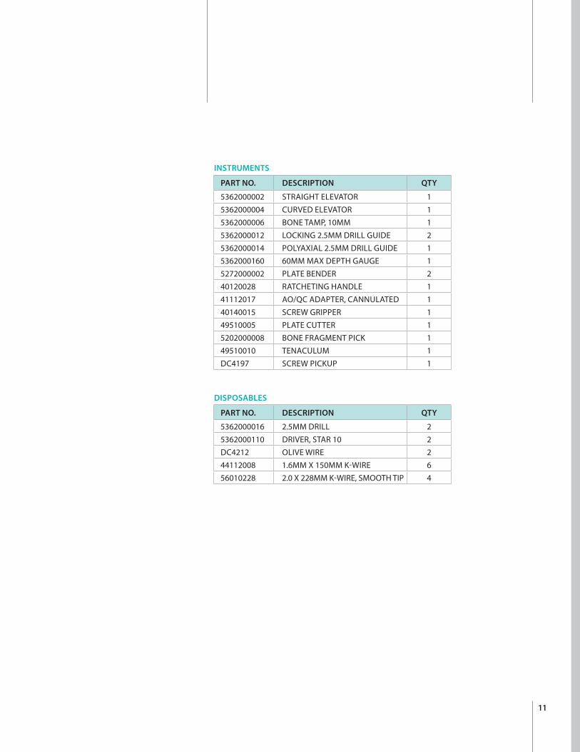
INSTRUMENTS
PART NO. DESCRIPTION QTY
5362000002 STRAIGHT ELEVATOR 15362000004 CURVED ELEVATOR 15362000006 BONE TAMP, 10MM 15362000012 LOCKING 2.5MM DRILL GUIDE 25362000014 POLYAXIAL 2.5MM DRILL GUIDE 15362000160 60MM MAX DEPTH GAUGE 15272000002 PLATE BENDER 240120028 RATCHETING HANDLE 141112017 AO/QC ADAPTER, CANNULATED 140140015 SCREW GRIPPER 149510005 PLATE CUTTER 15202000008 BONE FRAGMENT PICK 149510010 TENACULUM 1DC4197 SCREW PICKUP 1
DISPOSABLES
PART NO. DESCRIPTION QTY
5362000016 2.5MM DRILL 25362000110 DRIVER, STAR 10 2DC4212 OLIVE WIRE 244112008 1.6MM X 150MM K-WIRE 656010228 2.0 X 228MM K-WIRE, SMOOTH TIP 4

12
Ordering InformationCalcaneal Compression Screw System 3.5mm and 6.5mm* DARCO® Headed Screws
INSTRUMENTS*
PART NO. DESCRIPTION QTY
IW100627 DRILL SLEEVE 2.7MM DRILL 1IW120516 2.5MM HEX DRIVER FOR 3.5MM SCREWS 1IW791503 DEPTH GAUGE FOR 150MM K-WIRE 1IW200001 TISSUE SLEEVE 6.5MM SCREWS 1IW101027 DRILL SLEEVE FOR 6.5MM SCREWS 1IW230532 LARGE COUNTERSINK 6.5MM SCREWS 1IW240532 5MM HEX DRIVER FOR 6.5MM SCREWS 144180025 RATCHETING HANDLE, HUDSON 1IW792701 DEPTH GAUGE FOR 270MM K-WIRE 15362000170 TRAY 1IW130516 COUNTERSINK 1
3.5MM CANNULATED COMPRESSION SCREWS*
PART NO. DESCRIPTION QTY
SCN353032 30MM SHORT 2SCN353232 32MM SHORT 2SCN353432 34MM SHORT 2SCN353632 36MM SHORT 2SCN353832 38MM SHORT 2SCN354032 40MM SHORT 2SCN354232 42MM SHORT 2SCN354432 44MM SHORT 2SCN354632 46MM SHORT 2SCN354832 48MM SHORT 2SCN355032 50MM SHORT 2
6.5MM CANNULATED COMPRESSION SCREWS*
PART NO. DESCRIPTION QTY
SCN654062 40MM 2SCN654562 45MM 2SCN655062 50MM 2SCN655562 55MM 2SCN656062 60MM 2SCN656562 65MM 2SCN657062 70MM 2SCN657562 75MM 2SCN658062 80MM 2SCN658562 85MM 2
DISPOSABLES*
PART NO. DESCRIPTION QTY
IW702713 2.7MM DRILL 1NK011215 1.2MM THREADED TIP K-WIRE 150MM 2IW706522 4.4MM DRILL BIT FOR 6.5MM SCREWS 1NK112527 2.5MM K-WIRE 2
*Manufactured by AAP Implantate AG.


™Trademarks and ®Registered marks of Wright Medical Technology, Inc. ©2014 Wright Medical Technology, Inc.All Rights Reserved.
009924C 30-Oct-2014
Wright Medical Technology, Inc.1023 Cherry RoadMemphis, TN 38117800 238 7117901 867 9971www.wmt.com
Wright Medical EMEAAtlas Arena, Australia BuildingHoogoorddreef 71101 BA Amsterdamthe Netherlands011 31 20 565 9060
Wright Medical UK Ltd.Unit 1, Campus FiveLetchworth Garden CityHertfordshire SG6 2JF United Kingdom011 44 (0)845 833 4435