ortheast site solutions n 860-209-4690 denise ... · pdf file1,800 38,000 64,114 137,900...
TRANSCRIPT

Northeast Site Solutions Denise Sabo 199 Brickyard Rd Farmington, CT 06032 860-209-4690 [email protected]
July 6, 2016
Members of the Siting Council Connecticut Siting Council Ten Franklin Square New Britain, CT 06051
RE: Notice of Exempt Modification 75 Wells Road, Wethersfield CT 06109 Latitude: 41.705880
Longitude: -72.663330 T-Mobile Site#: CTHA506A_L700
Dear Ms. Bachman:
T-Mobile currently maintains three (3) antennas at the 95-foot level of the existing 103.5-foot monopole at 75 Wells Road, Wethersfield CT 06109. The tower is owned by Frontier Communications. The property is owned by Southern New England Telephone Co c/o Frontier Communications. T-Mobile now intends to relocate three (3) of its existing AIR21 antennas from the 75-foot level to the existing 95-foot level, install three (3) new 700 MHz antenna and extend (1) existing hybrid cable. The new antennas would be installed at the 95-foot level of the tower. Planned Modifications:
Remove: NONE
Remove and Replace: (3)AIR21 B2A /B4P (REMOVE from 75-Foot RAD) - (3)AIR21 B2A /B4P (REPLACE to 95-Foot RAD)
Install New: (3)Ericsson KRC 118 057/1 Antenna
(3) RRUS11 B12 (3) T-Arm Mounts
Existing to Remain: (6) 7/8” Coax (1) Extend Existing 1-5/8” Hybrid Cable
This facility was approved by the Connecticut Siting Council. File No – Springwich Cellular Ltd. Partnership notice of intent to replace an existing telecommunications facility located at 75 Wells Rd., Wethersfield. Please see attached documentation.

Please accept this letter as notification pursuant to Regulations of Connecticut State Agencies§ 16- SOj-73, for construction that constitutes an exempt modification pursuant to R.C.S.A. § 16-50j-72(b)(2). In accordance with R.C.SA. § 16-SOj-73, a copy of this letter is being sent to Town Manager Jeff Bridges, Elected Official for the Town of Wethersfield, as well as the property owner and the tower owner. The planned modifications to the facility fall squarely within those activities explicitly provided for in R.C.S;A. § 16-50j-72(b)(2).
1. The proposed modifications will not result in an increase in the height of the existing structure. 2. The proposed modifications will not require the extension of the site boundary. 3. The proposed modifications will not increase noise levels at the facility by six decibels or more, or to levels that exceed state and local criteria. 4. The operation of the replacement antennas will not increase radio frequency emissions at the facility to a level at or above the Federal Communications Commission safety standard. 5. The proposed modifications will not cause a change or alteration in the physical or environmental characteristics of the site. · 6. The existing structure and its foundation can support the proposed loading. For the foregoing reasons, T-Mobile respectfully submits that the proposed modifications to the above referenced telecommunications facility constitute an exempt modification under R.C.S.A. § 16-50j-72(b)(2).
Sincerely,
Denise Sabo Mobile: 860-209-4690 Fax: 413-521-0558 Office: 199 Brickyard Rd, Farmington, CT 06032 Email: [email protected]
Attachments
cc: Jeff Bridges, Town Manager - as elected official Frontier Communications - as tower owner

Southern New England Telephone Co c/o Frontier Communications - as property owner


Other ID:
CURRENT OWNER TOPO. UTILITIES STRT./ROAD LOCATION CURRENT ASSESSMENTDescription Code Appraised Value Assessed Value
SUPPLEMENTAL DATA
UTILITYUTILITYUTILITY
400400400
409,000131,600333,600
286,30092,100
233,500
Total 874,200 611,900
WETHERSFIELD, CT6159
SOUTHERN N E TELEPHONE COC/O FRONTIER COMMUNICATIONS401 MERRITT 7TAX DEPTNORWALK, CT 06851Additional Owners:
VISIONGIS ID: 205069
BK-VOL/PAGE SALE DATE q/u v/i SALE PRICE V.C. PREVIOUS ASSESSMENTS (HISTORY)0121/0472 11/30/1946 U 0
EXEMPTIONS OTHER ASSESSMENTS This signature acknowledges a visit by a Data Collector or AssessorYear Description Amount Code Description Number Amount Comm. Int.
APPRAISED VALUE SUMMARY
NOTES
Net Total Appraised Parcel Value 874,200
409,000
0
333,600
131,600
0
874,200
Appraised Bldg. Value (Card)
RECORD OF OWNERSHIP
SNET/NOW FRONTIER
NO ACCESS TO UQS - STAIRS REMOVED
SOUTHERN N E TELEPHONE CO
CONTROL SWITCH BUILDING
NO OFFICE FIT UP
ECON=MKT/USE FUNC=OVERBUILT
2009 NVI
ZONING CHANGE PER PLANNING
60 X 36 SLATE ROOF
TOWER VALUE= 3000 X 12= 36,000-15% EXP=
30,600/.11 CAP= 278,200/SITE
AT+T TELEPHONE/BAA#68
C
BUILDING PERMIT RECORDPermit ID Issue Date Type Description Amount Insp. Date % Comp. Date Comp. Comments Date ID Cd. Purpose/ResultE-15-251E-15-284B-15-26E-13-8
M-10-24B-10-119MP-0199
07/20/201507/20/201503/05/201501/14/201307/28/201007/08/201012/23/2009
ELELCMELHABPHA
ElectricElectricCommercialElectricHVAC
HVAC
2,0001,500
36,4531,800
38,00064,114
137,900
09/22/201509/22/201509/22/201504/11/201310/14/201010/14/201010/14/2010
100100100100100100100
07/20/201510/01/201510/01/201510/01/201310/01/201010/01/201010/01/2010
INSTALL NEW 200 AMP METER & NEW ELECTRICAL FOR T-MOBILE CABINET W/ PIPING & FIBERINSTALL SURFACE MOUNT FEED IN RIGID PIPE FROM METER TO NEW PPC CABINET16x10 CONCRETE PAD, ANTENNA T ANN MOUNTING TO EXISTING TOWER. 16 NEW ANTENNAS, 8' HIGH ICE BRIDGE, 1 GPS ANTENNA MOUNTED TO ICE BRIDGE SUPPORT, 2 CABINETS ON CONCRETE PAD. ONE CABINET ON POST, 10 COAX LINES & 1 FIBER LINEINSTALL NEW 200 AMP PANEL ON EXISTING METER CANReplace existing a/c split sys. & ductworkInstsall reinforcement to existing 101.5' monopole tower.Install 3 split a/c systems & ducts on roof
06/23/201503/20/201401/03/201404/11/201310/14/2010
CRCRJLCRCR
4421414949
No Change Reinspection RereviewBAA Hearing-No ChangeHearing-ChangeNo Change After Inspection followiNo Change After Inspection followi
LAND LINE VALUATION SECTION
LOT NO 3ACALLBACKCENSUS 4922SECTION 3 DISBLD EX
Notice 1 ValPENALTYSEQ NOSIDE N10
900130
$740,700
Appraised XF (B) Value (Bldg)Appraised OB (L) Value (Bldg)Appraised Land Value (Bldg)Special Land Value
Total Appraised Parcel ValueValuation Method:
Total:ASSESSING NEIGHBORHOOD
Type ISVISIT/ CHANGE HISTORY
ASSOC PID#
Adjustment: 0
Type
Yr. Code Assessed Value Yr. Code Assessed Value Yr. Code Assessed Value400400
680,50092,100
201020102010
400400400
429,50092,100
251,000
200820082008
400400400
429,50092,100
251,000
Total: 772,600 Total: Total:
20122012
NBHD/ SUB0001/A
NBHD Name Street Index Name Tracing Batch
772,600 772,600
B#1
Total Card Land Units:
400C
Use Code
UseDescription
Pub Utilit MDL-96 SRD/AZone D Front Depth
0.90Units
AC
AC0.90 Parcel Total Land Area:
135,000.00 1.0833I. Factor
Unit Price S.A.
I
0.9 AC
C. Factor1.00 006
ST.Idx Adj.
1.00
Total Land Value:
Notes- Adj Special Pricing146,245.50
Adj. Unit Price Land Value131,600
131,600
Property Location: 75 WELLS RD MAP ID:205/ 069/ / /Bldg #: 1 of 1 Card 1 of 1 Print Date:11/23/2015 13:47Vision ID: 9038 Account #
Parcel Description205-069-
Bldg Name: State Use:400Sec #: 1 ofof 1
S AdjFact
1.00

FUSBASBSM
BAS
UQSBAS
BAS
62
83
61
36
1
47
59
35
60
34
11
36
601
18
Model
CONSTRUCTION DETAILElement Cd. Ch. Description
COST/MARKET VALUATION
BUILDING SUB-AREA SUMMARY SECTIONCode
Ttl. Gross Liv/Lease Area:
Style
Grade
Occupancy
Exterior Wall 2Roof StructureRoof CoverInterior Wall 1
Exterior Wall 1
Interior Wall 2Interior Floor 1Interior Floor 2Heating FuelHeating TypeAC Type
Bldg Use
79 Telephone Bldg96 Ind/Comm03 Average
120 Brick27 Pre-finsh Metl01 Flat04 Tar + Gravel03 Plaster
Total RoomsTotal BedrmsTotal Baths
Heat/ACFrame TypeBaths/PlumbingCeiling/WallRooms/PrtnsWall Height% Comn Wall
MIXED USE
Element Cd. Ch. DescriptionCONSTRUCTION DETAIL (CONTINUED)
05 Vinyl/Asphalt
02 Oil/Gas05 Hot Water03 Central
400C Pub Utilit MDL-96
000
02 HEAT/AC SPLIT03 MASONRY02 AVERAGE06 CEIL & WALLS02 AVERAGE100
Code400C
DescriptionPub Utilit MDL-96
Percentage100
BASBSMFUSUQS
DescriptionFirst FloorBasementFinished Upper StoryUnfinished 3/4 Story
Living Area9,387
0
05,110
Gross Area9,387
14,497
5,1105,1102,160
21,767
Eff. Area Unit Cost Undeprec. Value
Apr Value2,90052,500278,200
Adj. Base Rate: 138.69
AYB
Dep CodeRemodel RatingYear RemodeledDep %Functional ObslncExternal ObslncCost Trend Factor
1939
G
303517
Condition% CompleteOverall % CondApprais ValDep % OvrDep Ovr CommentMisc Imp OvrMisc Imp Ovr CommentCost to Cure OvrCost to Cure Ovr Comment
18409,0000
0
0
OB-OUTBUILDING & YARD ITEMS(L) / XF-BUILDING EXTRA FEATURES(B)Code SubDescription
PAV1CB3
Asphalt PavingPreCastConCelCELL SITE
Sub Descript L/BLLL
Units2,4002001
Unit Price Yr Gde Dp Rt Cnd %Cnd1.60350.00278,200.00
19992003
GG
7575
Property Location: 75 WELLS RD MAP ID:205/ 069/ / /Bldg #: 1 of 1 Card 1 of 1 Print Date:11/23/2015 13:47Vision ID: 9038 Account #
Parcel Description205-069-
Bldg Name: State Use:400Sec #: 1 ofof 1

TownofWethersfield,CT June17,2016
PropertyInformation
PropertyID
205069
Location 75WELLSRDOwner SOUTHERNNETELEPHONECO
MAPFORREFERENCEONLYNOTALEGALDOCUMENT
TownofWethersfield,CTmakesnoclaimsandnowarranties,expressedorimplied,concerningthevalidityoraccuracyoftheGISdatapresentedonthismap.
1"=96ft


CTHA506A
AT&T WETHERSFIELD
MONOPOLE
75 WELLS ROAD
WETHERSFIELD, CT
T-MOBILE NORTHEAST, LLC35 GRIFFIN ROAD SOUTHBLOOMFIELD, CT 06002OFFICE: (860) 692-7100
FAX:(860) 692-7159
CHECKED BY:
DRAWN BY:
PROJECT NO:
SUBMITTALS
F RESITE LLC
Innovative design solutions
Foresitellc.com
462 WALNUT STREET
NEWTON, MA 02460
TEL:617-527-3031
T-MOBILE NORTHEAST LLC

CTHA506A
AT&T WETHERSFIELD
MONOPOLE
75 WELLS ROAD
WETHERSFIELD, CT
T-MOBILE NORTHEAST, LLC35 GRIFFIN ROAD SOUTHBLOOMFIELD, CT 06002OFFICE: (860) 692-7100
FAX:(860) 692-7159
CHECKED BY:
DRAWN BY:
PROJECT NO:
SUBMITTALS
F RESITE LLC
Innovative design solutions
Foresitellc.com
462 WALNUT STREET
NEWTON, MA 02460
TEL:617-527-3031
SCALE 1"=8' (11x17)
0 8 16 24
1"=4' (24x36)
SITE PLANSCALE 1"=8' (11x17)
1"=4' (24x36)

SCALE: N.T.S
ANTENNA MOUNT DETAIL
CTHA506A
AT&T WETHERSFIELD
MONOPOLE
75 WELLS ROAD
WETHERSFIELD, CT
T-MOBILE NORTHEAST, LLC35 GRIFFIN ROAD SOUTHBLOOMFIELD, CT 06002OFFICE: (860) 692-7100
FAX:(860) 692-7159
CHECKED BY:
DRAWN BY:
PROJECT NO:
SUBMITTALS
F RESITE LLC
Innovative design solutions
Foresitellc.com
462 WALNUT STREET
NEWTON, MA 02460
TEL:617-527-3031
SCALE 1"=16' (11x17)
0 16 32 48
1"=8' (24x36)
SCALE 1"=16' (11x17)
1"=8' (24x36)
ELEVATION
ANTENNA PLANSCALE: N.T.S
59.0"
14.8"9.45"
SCALE: N.T.S
ERICSSON KRC- 118 057/1ANTENNA DETAIL
SCALE: N.T.S
17"
20"
7"
7
"
RRU S11 B12 DETAILS

CTHA506A
AT&T WETHERSFIELD
MONOPOLE
75 WELLS ROAD
WETHERSFIELD, CT
T-MOBILE NORTHEAST, LLC35 GRIFFIN ROAD SOUTHBLOOMFIELD, CT 06002OFFICE: (860) 692-7100
FAX:(860) 692-7159
CHECKED BY:
DRAWN BY:
PROJECT NO:
SUBMITTALS
F RESITE LLC
Innovative design solutions
Foresitellc.com
462 WALNUT STREET
NEWTON, MA 02460
TEL:617-527-3031
SCALE: N.T.SSCALE: N.T.S
702CC CONFIGURATIONANTENNA DETAILSCOAX/FIBER PLUMBING DIAGRAMGROUNDING DIAGRAM
REAROF
ANTENNA
LEGEND
LTE 700
ANTENNA #3
702CUALPHA ANTENNA VIEW
UN
DE
RS
IDE
OF
RR
US
11
AIR21 INTERFACE DETAIL

CTHA506A
AT&T WETHERSFIELD
MONOPOLE
75 WELLS ROAD
WETHERSFIELD, CT
T-MOBILE NORTHEAST, LLC35 GRIFFIN ROAD SOUTHBLOOMFIELD, CT 06002OFFICE: (860) 692-7100
FAX:(860) 692-7159
CHECKED BY:
DRAWN BY:
PROJECT NO:
SUBMITTALS
F RESITE LLC
Innovative design solutions
Foresitellc.com
462 WALNUT STREET
NEWTON, MA 02460
TEL:617-527-3031
GROUND BAR DETAILSCALE: N.T.S
BURNDY GROUNDING PRODUCTSSCALE: N.T.S
CADWELD GROUNDING CONNECTION PRODUCTSSCALE: N.T.S
GROUNDING TERMINATION MATRIXSCALE: N.T.S
TYPICAL GROUND BAR CONNECTIONS DETAILSCALE: N.T.S
GROUND BAR DETAILSCALE: N.T.S
BURNDY GROUNDING DETAILSSCALE: N.T.S


Rigorous Structural Analysis Report
T-Mobile – AT&T Wethersfield Monopole #CTHA506A
Owner: Frontier Communications - Wethersfield CO Site Wethersfield, Connecticut
June 01, 2016
MEI PROJECT ID: CT04861M-16V2
17950 PRESTON ROAD, SUITE 720 DALLAS, TEXAS 75252 TEL. 972 -783-2578 FAX 972-783-2583 www.maloufengineering.com


NORTHEAST SITE SOLUTIONS / T-MOBILE AT&T WETHERSFIELD MONOPOLE SITE #CTHA506A
MALOUF ENGINEERING INT’L, INC. MEI PROJECT ID CT04861M-16V2 - 06/01/16 - Pg. 3 This report is not to be reproduced or copied in whole or in part without MEI’s written consent. 2016, MEI, Inc. ©
TABLE OF CONTENTS
1. INTRODUCTION & SCOPE ______________________________________________ 4
2. SOURCE OF DATA _____________________________________________________ 4
Background Information: ------------------------------------------------------------------------------------------- 4
3. ANALYSIS CRITERIA ___________________________________________________ 5
Appurtenances Configuration ------------------------------------------------------------------------------------ 5
4. ANALYSIS PROCEDURE ________________________________________________ 6
Analysis Program ------------------------------------------------------------------------------------------------------- 6 Assumptions -------------------------------------------------------------------------------------------------------------- 6
5. ANALYSIS RESULTS ____________________________________________________ 7
6. FINDINGS & RECOMMENDATIONS ______________________________________ 8
7. REPORT DISCLAIMER __________________________________________________ 9
APPENDIX 1 - ANALYSIS PRINTOUT & GRAPHICS ______________________________ 10
APPENDIX 2 – SOURCE / CHANGED CONDITION ______________________________ 11

NORTHEAST SITE SOLUTIONS / T-MOBILE AT&T WETHERSFIELD MONOPOLE SITE #CTHA506A
MALOUF ENGINEERING INT’L, INC. MEI PROJECT ID CT04861M-16V2 - 06/01/16 - Pg. 4 This report is not to be reproduced or copied in whole or in part without MEI’s written consent. 2016, MEI, Inc. ©
1. INTRODUCTION & SCOPE A rigorous structural analysis was performed by Malouf Engineering Int’l (MEI), as requested and
authorized by Mr. Sheldon Freincle, Northeast Site Solutions, on behalf of T-Mobile, to determine
the acceptance of the proposed changed conditions in conformance with the IBC / ANSI/TIA-
222-G Standard, “Structural Standard for Antenna Supporting Structures and Antennas”.
The scope of this independent analysis is to determine the overall stability and the adequacy of
structural members, foundations, and member connections, as available and stated. This
analysis considers the structure to have been properly installed and maintained with no
structural defects. Installation procedures and related loading are not within the scope of this
analysis and should be performed and evaluated by a competent person of the erection
contractor.
The different report sections detail the applicable information used in this evaluation, relating to
the tower data, the appurtenances configuration and the wind and ice loading considered.
2. SOURCE OF DATA The following information has been used in this evaluation as source data that accurately
represent the existing structure and the related appurtenances:
Source Information Reference
STRUCTURE Tower MEI Records Previous Structural
Analysis ID CT04861M-16V1 Dated 05/04/2016
Foundation MEI Records Previous Structural Analysis
ID CT04861M-16V1 Dated 05/04/2016
Material Grade Not available from supplied documents-Assumed based on typical towers of this type-refer to Appendix
CURRENT APPURTENANCES MEI Records Previous Structural
Analysis ID CT04861M-16V1 Dated 05/04/2016
CHANGED CONDITION Frontier Comm. /
Ms. Elissa McOmber Prelim Data Questionnaire
Dated 04/20/2016
Background Information: Based on available information, the following is known regarding this structure:
DESIGNER / FABRICATOR Not Known / 18-Sided ORIGINAL DESIGN CRITERIA TIA/EIA 222-Unknown
PRIOR STRUCTURAL MODIFICATIONS As per GPD Group base plate and anchor rod modifications Job #2009264.50 dated 06/12/2009; pole shaft modifications by others as per B+T mapping report dated 07/17/2014 – considered properly installed.

NORTHEAST SITE SOLUTIONS / T-MOBILE AT&T WETHERSFIELD MONOPOLE SITE #CTHA506A
MALOUF ENGINEERING INT’L, INC. MEI PROJECT ID CT04861M-16V2 - 06/01/16 - Pg. 5 This report is not to be reproduced or copied in whole or in part without MEI’s written consent. 2016, MEI, Inc. ©
3. ANALYSIS CRITERIA
The structural analysis performed used the following criteria:
CODE / STANDARD 2009 Int’l Building Code / ANSI/TIA-222-G-2 Standard LOADING CASES Full Wind: 100 Mph (3-Sec Gust) - with No Radial Ice
Iced Case: 40 Mph + 1.25” Radial Ice Service: 60 Mph
STRUCTURE CRITERIA Structure Classification: Class II Exposure Category: ‘B’ – Topographic Category: 1
Appurtenances Configuration The following appurtenances configuration is denoted by the summation of Tables 1 & 2: Table 1: Proposed Changed Condition Appurtenances
Elev (ft)
Tenant Ants Qty
Appurtenance Model / Description Mount Description Lines Qty
Line size & Location
95 T-Mobile 3 Ericsson KRC 118 057/1 Panel Ants. (3) 12.5ft LP T-Arm Mounts (SitePro1 RMV12-3XX)
6 7/8”-(I) 3 RRUS-11 B12 Boxes
To Be Removed (See Below) 75 T-Mobile 3 AIR21 Panel Antennas (3) LP T-Arm Mounts Table 2: Remaining Current and Reserved/Future Appurtenances
Elev (ft)
Tenant Ants Qty
Appurtenance Model / Description Mount Description Lines Qty
Line size & Location
103.5
AT&T
6 AXCM-800/1900-90-13.5 Panel Ants. Top Platform w/ Rails (& Ladder)
12 2 1
1-5/8” 2-1/4” Hybrid Cables-(I) ATCB-B01-xxx Homerun Cable-(I/E)
3 AM-X-CD-16-65-00T-RET Panel Ants. 12 14.5"x9"x2.5" RRU/TMAs 3 17"x16.5"x6.5" RRU/TMAs 1 18"x19" (OVP / RRU) Boxes
101 1 5ft Lightning Rod 1 Beacon/Strobe 1 1/2”-(I)
95
T-Mobile
3
AIR21 Panel Antennas [Relocated from Elev. 75ft to Elev. 95tf]
1 1-5/8” Hybrid-Fiber-(I) [Extended as required]
46.5 1 GPS Antenna 18in Approx. Standoff Arm 1 3/8”-(E) 37 1 GPS Antenna 18in Approx. Standoff Arm 1 3/8”-(E) Notes: 1. All elevations are measured from tower base. 2. Please note appurtenances not listed above are to be removed/not present as per data supplied. 3. (I) = Internal; (E) = External; (FZ) = Within Face Zone; (OFZ) = Outside Face Zone - as per TIA-222-G. 4. The above appurtenances represent MEI’s understanding of the appurtenances configuration. If different
than above, the analysis is invalid. Please contact MEI if any discrepancies are found.

NORTHEAST SITE SOLUTIONS / T-MOBILE AT&T WETHERSFIELD MONOPOLE SITE #CTHA506A
MALOUF ENGINEERING INT’L, INC. MEI PROJECT ID CT04861M-16V2 - 06/01/16 - Pg. 6 This report is not to be reproduced or copied in whole or in part without MEI’s written consent. 2016, MEI, Inc. ©
4. ANALYSIS PROCEDURE
The subject structure is analyzed for feasibility of the installation of the proposed changed
condition previously noted. The data records furnished were reviewed and a computer stress
analysis was performed in accordance with the TIA-222 Standard provisions and with the agreed
scope of work terms and the results of this analysis are reported.
Analysis Program The computer program used to model the structure is a rigorous Finite Element Analysis program, tnxTower (ver. 7.0.5), a commercially available program by Tower Numerics Inc. The latticed structures members are modeled using beam/truss and cable members and the pole members using tubular beam elements. The structural parameters and geometry of the members are included in the model. The dead and temperature loads and the wind loads are internally calculated by the program for the different wind directions and then applied as external loads on the structure. Any applicable exemptions, as per Section 15.6 of the TIA-222-G Standard for existing structures originally designed in accordance with a previous revision of the TIA-222 Standard, have been taken.
Assumptions This engineering study is based on the theoretical capacity of the members and is not a condition assessment of the structure. This analysis is based on information supplied, and therefore, its results are based on and as accurate as that supplied data. MEI has made no independent determination, nor is it required to, of its accuracy. The following assumptions were made for this structural stress analysis:
This existing tower is assumed, for the purpose of this analysis, to have been properly maintained and to be in good condition with no structural defects and with no deterioration to its member capacities (‘as-new’ condition).
The tower member sizes and configuration are considered accurate as supplied. The material grade is as per data supplied and/or as assumed and as stated.
The appurtenances configuration is as supplied and/or as stated in the report. It is assumed to be complete and accurate. All antennas, mounts, coax and waveguides are assumed to be properly installed and supported as per manufacturer requirements.
Some assumptions are made regarding antennas and mounts sizes and their projected areas based on best interpretation of data supplied and of best knowledge of antenna type & industry practice.
Mounts/Platforms are considered adequate to support the loading. No actual analysis of the platform/mount itself is performed, with the analysis being limited to analyzing the structure.
The soil parameters are as per data supplied or as assumed and stated in the calculations. Refer to the Appendix. If no data is available, the foundation system is assumed to support the structure with its new reactions.
All welds and connections are assumed to develop at least the member capacity, unless determined otherwise and explicitly stated in this report.
All prior structural modifications, if any, are assumed to be as per data supplied/available, and to have been properly installed and to be fully effective.
If any of the above assumptions are not valid or have been made in error, this analysis results may be invalided, MEI should be contacted to review any contradictory information to determine its effect.
NORTHEAST SITE SOLUTIONS / T-MOBILE AT&T WETHERSFIELD MONOPOLE SITE #CTHA506A
MALOUF ENGINEERING INT’L, INC. MEI PROJECT ID CT04861M-16V2 - 06/01/16 - Pg. 7 This report is not to be reproduced or copied in whole or in part without MEI’s written consent. 2016, MEI, Inc. ©
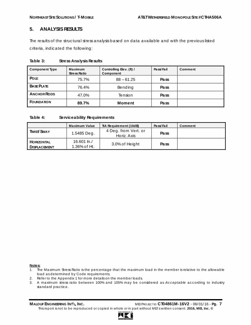
5. ANALYSIS RESULTS The results of the structural stress analysis based on data available and with the previous listed
criteria, indicated the following:
Table 3: Stress Analysis Results
Component Type Maximum Stress Ratio
Controlling Elev. (ft) / Component
Pass/Fail Comment
POLE 75.7% 88 – 61.25 Pass
BASE PLATE 76.4% Bending Pass
ANCHOR RODS 47.0% Tension Pass
FOUNDATION 89.7% Moment Pass
Table 4: Serviceability Requirements
Maximum Value TIA Requirement (10dB) Pass/Fail Comment
TWIST/SWAY 1.5485 Deg. 4 Deg. from Vert. or Horiz. Axis Pass
HORIZONTAL DISPLACEMENT
16.601 In./ 1.36% of Ht. 3.0% of Height Pass
Notes: 1. The Maximum Stress Ratio is the percentage that the maximum load in the member is relative to the allowable
load as determined by Code requirements. 2. Refer to the Appendix 1 for more details on the member loads. 3. A maximum stress ratio between 100% and 105% may be considered as Acceptable according to industry
standard practice.

NORTHEAST SITE SOLUTIONS / T-MOBILE AT&T WETHERSFIELD MONOPOLE SITE #CTHA506A
MALOUF ENGINEERING INT’L, INC. MEI PROJECT ID CT04861M-16V2 - 06/01/16 - Pg. 8 This report is not to be reproduced or copied in whole or in part without MEI’s written consent. 2016, MEI, Inc. ©
6. FINDINGS & RECOMMENDATIONS
Based on the rigorous stress analysis results, the subject structure is rated at 89.7% of its
support capacity (controlling component: Foundation) with the proposed changed
condition considered. Please refer to Table 3 and to Appendix 1 for more details of the
analysis results.
Based on the stress analysis performed, the existing structure is in conformance with the IBC
/ ANSI/TIA 222-G Standard for the loading considered under the criteria listed and
referenced in the report sections.
The installation of the proposed changed condition as noted in Table 1 is structurally
acceptable. Please refer to Appendix 1 for Schematic Lines Layout.
This structure has limited additional support capacity for the appurtenances and loading
criteria considered. Therefore, no changes to the configuration considered should be
made without performing a new proper evaluation.
Rigging and temporary supports required for the erection/modification shall be determined, documented, furnished and installed by the erector/contractor accounting for the loads imposed on the structure due to the proposed construction method.

NORTHEAST SITE SOLUTIONS / T-MOBILE AT&T WETHERSFIELD MONOPOLE SITE #CTHA506A
MALOUF ENGINEERING INT’L, INC. MEI PROJECT ID CT04861M-16V2 - 06/01/16 - Pg. 9 This report is not to be reproduced or copied in whole or in part without MEI’s written consent. 2016, MEI, Inc. ©
7. REPORT DISCLAIMER The engineering services rendered by Malouf Engineering International, Inc. ('MEI') in connection with this
Structural Analysis are limited to a computer analysis of the tower structure, size and capacity of its
members. MEI does not analyze the fabrication, including welding and connection capacities, except as
included in this Report.
The analysis performed and the conclusions contained herein are based on the assumption that the tower has been properly installed and maintained, including, but not limited to the following:
1. Proper alignment and plumbness. 2. Correct guy tensions, as applicable. 3. Correct bolt tightness or slip jacking of sleeved connections. 4. No significant deterioration or damage to any structural component.
Furthermore, the information and conclusions contained in this Report were determined by application of the current “state-of-the-art” engineering and analysis procedures and formulae. MALOUF ENGINEERING INTERNATIONAL, INC. assumes no obligation to revise any of the information or conclusions contained in this Report in the event that such engineering and analysis procedures and formulae are hereafter modified or revised. In addition, under no circumstances will MALOUF ENGINEERING INTERNATIONAL, INC. have any obligation or responsibility whatsoever for or on account of consequential or incidental damages sustained by any person, firm or organization as a result of any information or conclusions contained in the Report, and the maximum liability of MALOUF ENGINEERING INTERNATIONAL, INC., if any, pursuant to this Report shall be limited to the total funds actually received by MALOUF ENGINEERING INTERNATIONAL, INC. for preparation of this Report. Customer has requested MALOUF ENGINEERING INTERNATIONAL, INC. to prepare and submit to Customer an engineering analysis with respect to the Subject Tower and has further requested MALOUF ENGINEERING INTERNATIONAL, INC. to make appropriate recommendations regarding suggested structural modifications and changes to the Subject Tower. In making such request of MALOUF ENGINEERING INTERNATIONAL, INC., Customer has informed MALOUF ENGINEERING INTERNATIONAL, INC. that Customer will make a determination as to whether or not to implement any of the changes or modifications which may be suggested by MALOUF ENGINEERING INTERNATIONAL, INC. and that Customer will have any such changes or modifications made by riggers, erectors and other subcontractors of Customer’s choice. MALOUF ENGINEERING INTERNATIONAL, INC. shall have the right to rely upon the accuracy of the information supplied by the customer and shall not be held responsible for the Customer’s misrepresentation or omission of relevant fact whether intentional or otherwise. Customer hereby agrees and acknowledges that MALOUF ENGINEERING INTERNATIONAL, INC. shall have no liability whatsoever to Customer or to others for any work or services performed by any persons other than MALOUF ENGINEERING INTERNATIONAL, INC. in connection with the implementation of services including but not limited to any services rendered for Customer or for others by riggers, erectors or other subcontractors. Customer acknowledges and agrees that any riggers, erectors or subcontractors retained or employed by Customer shall be solely responsible to Customer and to others for the quality of work performed by them and that MALOUF ENGINEERING INTERNATIONAL, INC. shall have no liability or responsibility whatsoever as a result of any negligence or breach of contract by any such rigger, erector or subcontractor and that Customer and rigger, erector, or subcontractor will provide MALOUF ENGINEERING INTERNATIONAL, INC. with a Certificate of Insurance naming MALOUF ENGINEERING INTERNATIONAL, INC. as additional insured.

NORTHEAST SITE SOLUTIONS / T-MOBILE AT&T WETHERSFIELD MONOPOLE SITE #CTHA506A
MALOUF ENGINEERING INT’L, INC. MEI PROJECT ID CT04861M-16V2 - 06/01/16 - Pg. 10 This report is not to be reproduced or copied in whole or in part without MEI’s written consent. 2016, MEI, Inc. ©
APPENDIX 1 - ANALYSIS PRINTOUT & GRAPHICS

maloufengineering.com
MALOUF ENGINEERING INT'L. INC. 17950 PRESTON RD. SUITE 720
DALLAS, TEXAS - 75252 Phone: (972) 783-2578 FAX: (972) 783-2583
Job: 101 ft. MNP. / AT&T Wethersfield Site #CTHA506A Project: CT04861M-16V2 Client: Northeast Site Solutions / T-Mobile Drawn by: HLopez App'd:
Code: TIA-222-G Date: 06/01/16 Scale: NTS Path:
C:\MEIProjects\16files\MNP\CT04861M-16V2\CT04861M-16V2_Rev-G.eri Dwg No. E-1
101.0 ft
88.0 ft
61.3 ft
56.3 ft
51.8 ft
46.3 ft
40.0 ft
35.0 ft
30.0 ft
25.0 ft
20.0 ft
15.0 ft
10.0 ft
5.0 ft
0.0 ft
REACTIONS - 100 mph WINDTORQUE 0 kip-ft
14 KSHEAR
1020 kip-ftMOMENT
20 KAXIAL
40 mph WIND - 1.2500 in ICETORQUE 0 kip-ft
3 KSHEAR
267 kip-ftMOMENT
47 KAXIAL
ARE FACTOREDALL REACTIONS
Sec
tion
12
34
56
78
910
1112
1314
(2) AXCM-800/1900-90-13.5 w/ Pipe Mount (ATT / E)
103.5 (2) AXCM-800/1900-90-13.5 w/ Pipe Mount (ATT / E)
103.5 (2) AXCM-800/1900-90-13.5 w/ Pipe Mount (ATT / E)
103.5 AM-X-CD-16-65-00T-RET w/ PIPE MOUNT (ATT / E)
103.5 AM-X-CD-16-65-00T-RET w/ PIPE MOUNT (ATT / E)
103.5 AM-X-CD-16-65-00T-RET w/ PIPE MOUNT (ATT / E)
103.5 (4) 14.5"x9"x2.5" RRU/TMA (ATT / E) 103.5 (4) 14.5"x9"x2.5" RRU/TMA (ATT / E) 103.5 (4) 14.5"x9"x2.5" RRU/TMA (ATT / E) 103.5 17"x16.5"x6.5" RRU/TMA (ATT / E) 103.5 17"x16.5"x6.5" RRU/TMA (ATT / E) 103.5 17"x16.5"x6.5" RRU/TMA (ATT / E) 103.5 18"x19" (OVP / RRU) (ATT / E) 103.5 Top Platform w/ Rails ( Ladder) (E) 103.5 5' Lightning Rod (E) 101 Beacon/Strobe (E) 101 AIR21 w/ pipe Mount (T-Mobile / E (Relocated))
95 AIR21 w/ pipe Mount (T-Mobile / E (Relocated))
95 AIR21 w/ pipe Mount (T-Mobile / E (Relocated))
95 Ericsson KRC 118 057/1 w/ pipe Mount (T-Mobile / P)
95 Ericsson KRC 118 057/1 w/ pipe Mount (T-Mobile / P)
95 Ericsson KRC 118 057/1 w/ pipe Mount (T-Mobile / P)
95 RRUS-11 B12 (T-Mobile / P) 95 RRUS-11 B12 (T-Mobile / P) 95 RRUS-11 B12 (T-Mobile / P) 95 12.5 ft. L.P. T-Arm Mount (SitePro1 RMV12-3XX) (Prop.)
95 12.5 ft. L.P. T-Arm Mount (SitePro1 RMV12-3XX) (Prop.)
95 12.5 ft. L.P. T-Arm Mount (SitePro1 RMV12-3XX) (Prop.)
95 GPS (E) 46.5 18" Approx. Standoff Arm (E) 46.5 GPS (E) 37 18" Approx. Standoff Arm (E) 37DESIGNED APPURTENANCE LOADINGTYPE TYPEELEVATION ELEVATION
(2) AXCM-800/1900-90-13.5 w/ Pipe Mount (ATT / E)
103.5
(2) AXCM-800/1900-90-13.5 w/ Pipe Mount (ATT / E)
103.5
(2) AXCM-800/1900-90-13.5 w/ Pipe Mount (ATT / E)
103.5
AM-X-CD-16-65-00T-RET w/ PIPE MOUNT (ATT / E)
103.5
AM-X-CD-16-65-00T-RET w/ PIPE MOUNT (ATT / E)
103.5
AM-X-CD-16-65-00T-RET w/ PIPE MOUNT (ATT / E)
103.5
(4) 14.5"x9"x2.5" RRU/TMA (ATT / E) 103.5
(4) 14.5"x9"x2.5" RRU/TMA (ATT / E) 103.5
(4) 14.5"x9"x2.5" RRU/TMA (ATT / E) 103.5
17"x16.5"x6.5" RRU/TMA (ATT / E) 103.5
17"x16.5"x6.5" RRU/TMA (ATT / E) 103.5
17"x16.5"x6.5" RRU/TMA (ATT / E) 103.5
18"x19" (OVP / RRU) (ATT / E) 103.5
Top Platform w/ Rails ( Ladder) (E) 103.5
5' Lightning Rod (E) 101
Beacon/Strobe (E) 101
AIR21 w/ pipe Mount (T-Mobile / E (Relocated))
95
AIR21 w/ pipe Mount (T-Mobile / E (Relocated))
95
AIR21 w/ pipe Mount (T-Mobile / E (Relocated))
95
Ericsson KRC 118 057/1 w/ pipe Mount (T-Mobile / P)
95
Ericsson KRC 118 057/1 w/ pipe Mount (T-Mobile / P)
95
Ericsson KRC 118 057/1 w/ pipe Mount (T-Mobile / P)
95
RRUS-11 B12 (T-Mobile / P) 95
RRUS-11 B12 (T-Mobile / P) 95
RRUS-11 B12 (T-Mobile / P) 95
12.5 ft. L.P. T-Arm Mount (SitePro1 RMV12-3XX) (Prop.)
95
12.5 ft. L.P. T-Arm Mount (SitePro1 RMV12-3XX) (Prop.)
95
12.5 ft. L.P. T-Arm Mount (SitePro1 RMV12-3XX) (Prop.)
95
GPS (E) 46.5
18" Approx. Standoff Arm (E) 46.5
GPS (E) 37
18" Approx. Standoff Arm (E) 37
MATERIAL STRENGTHGRADE GRADEFy FyFu Fu
A572-65 65 ksi 80 ksi A572-60 60 ksi 75 ksi
TOWER DESIGN NOTES1. Tower is located in Hartford County, Connecticut.2. Tower designed for Exposure B to the TIA-222-G Standard.3. Tower designed for a 100 mph basic wind in accordance with the TIA-222-G Standard.4. Tower is also designed for a 40 mph basic wind with 1.25 in ice. Ice is considered to increase
in thickness with height.5. Deflections are based upon a 60 mph wind.6. Tower Structure Class II.7. Topographic Category 1 with Crest Height of 0.00 ft8. TOWER RATING: 76.4%


maloufengineering.com
MALOUF ENGINEERING INT'L. INC. 17950 PRESTON RD. SUITE 720
DALLAS, TEXAS - 75252 Phone: (972) 783-2578 FAX: (972) 783-2583
Job: 101 ft. MNP. / AT&T Wethersfield Site #CTHA506A Project: CT04861M-16V2 Client: Northeast Site Solutions / T-Mobile Drawn by: HLopez App'd:
Code: TIA-222-G Date: 06/01/16 Scale: NTS Path:
C:\MEIProjects\16files\MNP\CT04861M-16V2\CT04861M-16V2_Rev-G.eri Dwg No. E-5
TIA-222-G - Service - 60 mph Maximum Values
0
0
5
5
10
10
15
15
20
20
Deflection (in)101.00
88.00
61.25
56.25
51.75
46.25
40.00
35.00
30.00
25.00
20.00
15.00
10.00
5.00
0.00
Ele
vati
on
(ft
)
0
0
0.5
0.5
1
1
1.5
1.5
2
2
Tilt (deg)0
0
0.05
0.05
0.1
0.1
Twist (deg)101.00
88.00
61.25
56.25
51.75
46.25
40.00
35.00
30.00
25.00
20.00
15.00
10.00
5.00
0.00

ttnnxxTToowweerr Job
101 ft. MNP. / AT&T Wethersfield Site #CTHA506A
Page
1 of 5
MALOUF ENGINEERING INT'L. INC.
17950 PRESTON RD. SUITE 720
Project
CT04861M-16V2 Date
12:09:10 06/01/16
DALLAS, TEXAS - 75252 Phone: (972) 783-2578 FAX: (972) 783-2583
Client Northeast Site Solutions / T-Mobile
Designed by
HLopez
Tower Input Data There is a pole section. This tower is designed using the TIA-222-G standard. The following design criteria apply:
Tower is located in Hartford County, Connecticut. Basic wind speed of 100 mph. Structure Class II. Exposure Category B. Topographic Category 1. Crest Height 0.00 ft. Nominal ice thickness of 1.2500 in. Ice thickness is considered to increase with height. Ice density of 56 pcf. A wind speed of 40 mph is used in combination with ice. Temperature drop of 50 °F. Deflections calculated using a wind speed of 60 mph. A non-linear (P-delta) analysis was used. Pressures are calculated at each section. Stress ratio used in pole design is 1. Local bending stresses due to climbing loads, feed line supports, and appurtenance mounts are not considered.
Feed Line/Linear Appurtenances - Entered As Round Or Flat
Description Placement ft
Total Number
ATCB-B01-xxx Homerun Cable (AT&T / E)
101.00 - 62.00 1
3/8 (Shielded) (E)
46.50 - 0.00 1
3/8 (Shielded) (E)
37.00 - 0.00 1

ttnnxxTToowweerr Job
101 ft. MNP. / AT&T Wethersfield Site #CTHA506A
Page
2 of 5
MALOUF ENGINEERING INT'L. INC.
17950 PRESTON RD. SUITE 720
Project
CT04861M-16V2 Date
12:09:10 06/01/16
DALLAS, TEXAS - 75252 Phone: (972) 783-2578 FAX: (972) 783-2583
Client Northeast Site Solutions / T-Mobile
Designed by
HLopez
Feed Line/Linear Appurtenances - Entered As Area
Description Allow Shield
Component Type
Placement ft
Total Number
Safety Line 3/8 (E)
No CaAa (Out Of Face)
101.00 - 0.00 1
Step Bolts (E)
No CaAa (Out Of Face)
101.00 - 0.00 1
1/2 (E (Lighting))
No Inside Pole 101.00 - 0.00 1
1 5/8 (AT&T / E)
No Inside Pole 101.00 - 0.00 12
Hybrid Cable (2 1/4) (AT&T / E)
No Inside Pole 101.00 - 0.00 2
ATCB-B01-xxx Homerun Cable
(AT&T / E)
No Inside Pole 62.00 - 0.00 1
1 5/8 (Hybrid-Fiber) (T-Mobile / E)
No Inside Pole 95.00 - 0.00 1
7/8 (T-Mobile / P)
No Inside Pole 95.00 - 0.00 6
MP303 (Mods)
No CaAa (Out Of Face)
62.00 - 47.00 1
MP303 (Mods)
No CaAa (Out Of Face)
62.00 - 47.00 1
MP304 (Mods)
No CaAa (Out Of Face)
45.50 - 0.00 1
MP304 (Mods)
No CaAa (Out Of Face)
45.50 - 0.00 1

ttnnxxTToowweerr Job
101 ft. MNP. / AT&T Wethersfield Site #CTHA506A
Page
3 of 5
MALOUF ENGINEERING INT'L. INC.
17950 PRESTON RD. SUITE 720
Project
CT04861M-16V2 Date
12:09:10 06/01/16
DALLAS, TEXAS - 75252 Phone: (972) 783-2578 FAX: (972) 783-2583
Client Northeast Site Solutions / T-Mobile
Designed by
HLopez
Discrete Tower Loads
Description Face or
Leg
Placement ft
5' Lightning Rod (E)
A 101.00
Beacon/Strobe (E)
B 101.00
(2) AXCM-800/1900-90-13.5 w/ Pipe Mount
(AT&T / E)
A 103.50
(2) AXCM-800/1900-90-13.5 w/ Pipe Mount
(AT&T / E)
B 103.50
(2) AXCM-800/1900-90-13.5 w/ Pipe Mount
(AT&T / E)
C 103.50
AM-X-CD-16-65-00T-RET w/ PIPE MOUNT
(AT&T / E)
A 103.50
AM-X-CD-16-65-00T-RET w/ PIPE MOUNT
(AT&T / E)
B 103.50
AM-X-CD-16-65-00T-RET w/ PIPE MOUNT
(AT&T / E)
C 103.50
(4) 14.5''x9''x2.5'' RRU/TMA (AT&T / E)
A 103.50
(4) 14.5''x9''x2.5'' RRU/TMA (AT&T / E)
B 103.50
(4) 14.5''x9''x2.5'' RRU/TMA (AT&T / E)
C 103.50
17''x16.5''x6.5'' RRU/TMA (AT&T / E)
A 103.50
17''x16.5''x6.5'' RRU/TMA (AT&T / E)
B 103.50
17''x16.5''x6.5'' RRU/TMA (AT&T / E)
C 103.50
18''x19'' (OVP / RRU) (AT&T / E)
B 103.50
Top Platform w/ Rails (& Ladder)
(E)
A 103.50
Description Face or
Leg
Placement ft
AIR21 w/ pipe Mount (T-Mobile / E (Relocated))
A 95.00
AIR21 w/ pipe Mount (T-Mobile / E (Relocated))
B 95.00
AIR21 w/ pipe Mount (T-Mobile / E (Relocated))
C 95.00
Ericsson KRC 118 057/1 w/ pipe Mount
(T-Mobile / P)
A 95.00
Ericsson KRC 118 057/1 w/ pipe Mount
(T-Mobile / P)
B 95.00
Ericsson KRC 118 057/1 w/ pipe Mount
(T-Mobile / P)
C 95.00
RRUS-11 B12 (T-Mobile / P)
A 95.00
RRUS-11 B12 (T-Mobile / P)
B 95.00
RRUS-11 B12 (T-Mobile / P)
C 95.00
12.5 ft. L.P. T-Arm Mount (SitePro1 RMV12-3XX)
(Prop.)
A 95.00
12.5 ft. L.P. T-Arm Mount (SitePro1 RMV12-3XX)
(Prop.)
B 95.00
12.5 ft. L.P. T-Arm Mount (SitePro1 RMV12-3XX)
(Prop.)
C 95.00
GPS (E)
A 46.50
18'' Approx. Standoff Arm (E)
A 46.50
GPS (E)
A 37.00
18'' Approx. Standoff Arm (E)
A 37.00

ttnnxxTToowweerr Job
101 ft. MNP. / AT&T Wethersfield Site #CTHA506A
Page
4 of 5
MALOUF ENGINEERING INT'L. INC.
17950 PRESTON RD. SUITE 720
Project
CT04861M-16V2 Date
12:09:10 06/01/16
DALLAS, TEXAS - 75252 Phone: (972) 783-2578 FAX: (972) 783-2583
Client Northeast Site Solutions / T-Mobile
Designed by
HLopez
Maximum Tower Deflections - Service Wind
Section No.
Elevation ft
Horz. Deflection
in
Gov. Load
Comb.
Tilt °
Twist °
L1 101 - 88 16.601 40 1.5485 0.0016 L2 90.25 - 61.25 13.196 40 1.4568 0.0010 L3 61.25 - 56.25 5.820 40 0.9045 0.0004 L4 56.25 - 51.75 4.914 40 0.8257 0.0003 L5 51.75 - 46.25 4.170 40 0.7525 0.0003 L6 49 - 40 3.750 40 0.7066 0.0003 L7 40 - 35 2.511 40 0.5951 0.0002 L8 35 - 30 1.926 40 0.5228 0.0002 L9 30 - 25 1.417 40 0.4495 0.0001 L10 25 - 20 0.985 40 0.3755 0.0001 L11 20 - 15 0.631 40 0.3009 0.0001 L12 15 - 10 0.355 40 0.2259 0.0001 L13 10 - 5 0.158 40 0.1507 0.0000 L14 5 - 0 0.039 40 0.0754 0.0000
Critical Deflections and Radius of Curvature - Service Wind
Elevation ft
Appurtenance Gov. Load
Comb.
Deflection
in
Tilt °
Twist °
Radius of Curvature
ft 103.50 (2) AXCM-800/1900-90-13.5 w/
Pipe Mount 40 16.601 1.5485 0.0016 8968
101.00 5' Lightning Rod 40 16.601 1.5485 0.0016 8968 95.00 AIR21 w/ pipe Mount 40 14.680 1.5053 0.0013 7473 46.50 GPS 40 3.385 0.6720 0.0002 4704 37.00 GPS 40 2.151 0.5528 0.0002 3909

ttnnxxTToowweerr Job
101 ft. MNP. / AT&T Wethersfield Site #CTHA506A
Page
5 of 5
MALOUF ENGINEERING INT'L. INC.
17950 PRESTON RD. SUITE 720
Project
CT04861M-16V2 Date
12:09:10 06/01/16
DALLAS, TEXAS - 75252 Phone: (972) 783-2578 FAX: (972) 783-2583
Client Northeast Site Solutions / T-Mobile
Designed by
HLopez
Base Plate Design Data
Plate Thickness
in
Number of Anchor
Bolts
Anchor Bolt Size
in
Actual
Allowable Ratio Bolt
Tension K
Actual
Allowable Ratio
Concrete Stress
ksi
Actual
Allowable Ratio Plate Stress
ksi
Actual
Allowable Ratio
Stiffener Stress
ksi
Controlling Condition
Critical Ratio
2.500 8 1.7500 100.67 216.48 0.47
2.354 4.080 0.58
34.390 45.000 0.76
Plate 0.76
Section Capacity Table
Section No.
Elevation ft
Component Type
Size Critical Element
P K
øPallow
K %
Capacity Pass Fail
L1 101 - 88 Pole TP16.36x14.64x0.1875 1 -24.01 41.36 63.9 Pass L2 88 - 61.25 Pole TP19.7689x15.6873x0.25 2 -8.40 114.37 75.7 Pass L3 61.25 - 56.25 Pole TP20.4726x19.7689x0.250* 3 -9.06 195.73 55.9 Pass L4 56.25 - 51.75 Pole TP21.1059x20.4726x0.250* 4 -9.67 212.78 58.9 Pass L5 51.75 - 46.25 Pole TP21.88x21.1059x0.250* 5 -10.05 222.19 61.0 Pass L6 46.25 - 40 Pole TP22.28x20.725x0.3125* 6 -11.89 317.79 53.6 Pass L7 40 - 35 Pole TP22.995x22.28x0.3125* 7 -12.81 346.20 55.9 Pass L8 35 - 30 Pole TP23.71x22.995x0.3125* 8 -13.72 375.94 58.2 Pass L9 30 - 25 Pole TP24.425x23.71x0.3125* 9 -14.66 407.78 60.2 Pass L10 25 - 20 Pole TP25.14x24.425x0.3125* 10 -15.61 441.07 62.2 Pass L11 20 - 15 Pole TP25.855x25.14x0.3125* 11 -16.59 475.81 64.1 Pass L12 15 - 10 Pole TP26.57x25.855x0.3125* 12 -17.58 513.03 65.8 Pass L13 10 - 5 Pole TP27.285x26.57x0.3125* 13 -18.60 551.86 67.5 Pass L14 5 - 0 Pole TP28x27.285x0.3125* 14 -19.64 592.30 69.1 Pass
Summary Pole (L2) 75.7 Pass Base Plate 76.4 Pass RATING = 76.4 Pass
*Modified w/ MP304 & MP303 Channels Program Version 7.0.5.2 - 2/11/2016 File:C:/MEIProjects/16files/MNP/CT04861M-16V2/CT04861M-16V2_Rev-G.eri

NORTHEAST SITE SOLUTIONS / T-MOBILE AT&T WETHERSFIELD MONOPOLE SITE #CTHA506A
MALOUF ENGINEERING INT’L, INC. MEI PROJECT ID CT04861M-16V2 - 06/01/16 - Pg. 11 This report is not to be reproduced or copied in whole or in part without MEI’s written consent. 2016, MEI, Inc. ©
APPENDIX 2 – SOURCE / CHANGED CONDITION

A A
Type:Size:Length:# of runs:
Type:A A Size:
Length:# of runs:
Type:Size:Length:# of runs:
A AType:Size:Length:# of runs:
@ Existing Proposed Weight Azimuth RAD Center Attachment TipA x 124 lbs 20 95 95 99A x 124 lbs 150 95 95 99A x 124 lbs 255 95 95 99A x 91 lbs 20 95 95 97 Existing to be removedA x 91 lbs 20 95 95 97 Existing to be relocatedA x 91 lbs 150 95 95 97 Existing to be removedA x 91 lbs 150 95 95 97 Existing to be relocatedA x 91 lbs 255 95 95 97 Existing to be removedA x 91 lbs 255 95 95 97 Existing to be relocated
x 50.71 lbs ea 95 95 Three (3) RRU units
Ericsson AIR21 56” x 12” x 8”Ericsson AIR21 56” x 12” x 8”
Ericsson AIR21 56” x 12” x 8”Ericsson AIR21 56” x 12” x 8”
Ericsson AIR21 56” x 12” x 8”Ericsson AIR21 56” x 12” x 8”
4.9’ x 14.8“ x 9.5”Model
Ericsson KRC 118 057/1 4.9’ x 14.8“ x 9.5”
MakeAntenna & Ancillary Equipment Information Check one
Size / Dimensions
Receive Frequency 1740-1745
Ericsson KRC 118 057/1 4.9’ x 14.8“ x 9.5”Ericsson KRC 118 057/1
Notes: (including removals, ice shields, etc.)
7/8"956
Hybrid / fiber1-5/8"95
Transmit Frequency 2140-2145Output Power (watts) 40W
Transmit FrequencyEmission Type
1
Receive Frequency 1735-1740 Receive Frequency
LTE2130-2135
Receive FrequencyTransmitter ERP (dBm)Output Power (watts)
Transmitter ERP (dBm) 2 x 62,5 dBm
Class of Station AWEmission Type LTE
Class of StationCall Sign
Output Power (watts) 40WTransmitter ERP (dBm) 2 x 62,5 dBm
Output Power (watts)Transmitter ERP (dBm)
Call SignClass of Station
Emission Type LTETransmit Frequency 2135-2140
Emission TypeTransmit Frequency
Class of StationEmission TypeUMTS
40W2 x 62,5 dBm
Transmit FrequencyOutput Power (watts)
Heights - Above Ground Level (feet)
WQJQ696
Transmit FrequencyEmission Type
Call SignClass of Station CW
Call Sign
Coax
Receive FrequencyTransmitter ERP (dBm)
KNLF202
Class of Station AW
Call Sign WQGB373
Call Sign WQGA731
1930-1945 MHz
2 x 62,5 dBm1745-1755
WQPZ969AW
2145-215540W
LTE
2 x 62,5 dBm
Coax / Waveguide / Cable Information
40W2 x 62,5 dBm1730-1735
LTE728-73440W
698-704
WY
Ericsson RRUS 11 B12 19.69" x 16.97" x 7.17" ea
Transmitter ERP (dBm)
Tower / Radio Information - Call Sign information needs to be tied to a specific antenna(s). Adjust letters as needed.
WQKF358AW
Receive Frequency1850-1865 MHz
Output Power (watts)


Page 1 of 1 DESTEK ENGINEERING, LLC 1281 Kennestone Circle, Suite 100, Marietta, GA 30066 ‐ Tel: (770) 693‐0835
June 29, 2016 Mr. Saeed Mossavat Atlantis Group, Inc. 1340 Centre Street, Suite 212 Newtown, MA 02459 Re: 3rd Party Review T‐Mobile Site Name: AT&T Wethersfield Monopole T‐Mobile Site ID: CTHA506A Site Address: 75 Wells Road, Wethersfield, Hartford County, CT 06109 Destek Job Number: 1617016 Per your request, Destek Engineering, LLC (Destek) has reviewed the following documents and checked the analysis for conformance to currently adopted building codes and industry standards.
‐ Structural Analysis Report prepared by Malouf Engineering Intl., Inc., Project ID: CT04861M‐16V2, dated 06/01/2016, with E. Mark Malouf, PE as Engineer of Record.
Based on the information provided to Destek, it is our opinion that structural analysis prepared by Malouf Engineering Intl., Inc.:
Was not prepared to the currently adopted building code in this jurisdiction. More specifically, the analysis was prepared in accordance ANSI/TIA‐222‐G‐2 and The 2009 International Building Code. Currently, the entire state of Connecticut has adopted the 2005 Connecticut State Building Code, with various Supplements and Amendments. The State Building Code is modeled in accordance with the 2003 International Building Code. The 2003 International Building Code pre‐dates the adoption of ANSI/TIA‐222‐G, and thus the analysis should be prepared in accordance with ANSI/TIA/EIA‐222‐F.
Is missing the foundation calculations and/or reaction comparison. Thus, the reported maximum stress ratio for this element cannot be verified.
Provides limited software output and/or calculations related to the monopole and previous modification installations. Thus, the reported maximum stress ratios for these elements cannot be verified.
Should you need any clarifications about this letter, please contact me at (770) 693‐0835 or [email protected]. Sincerely, Destek Engineering, LLC 06/29/2016 Ahmet Colakoglu, PE CT Professional Engineer License No: 27057


EBI Consulting environmental | engineering | due diligence
21 B Street . Burlington, MA 01803 . Tel: (781) 273.2500 . Fax: (781) 273.3311
RADIO FREQUENCY EMISSIONS ANALYSIS REPORT EVALUATION OF HUMAN EXPOSURE POTENTIAL
TO NON-IONIZING EMISSIONS
T-Mobile Existing Facility
Site ID: CTHA506A
AT&T Wethersfield Monopole 75 Wells Road
Wethersfield, CT 06109
June 17, 2016
EBI Project Number: 6216002918
Site Compliance Summary
Compliance Status: COMPLIANT
Site total MPE% of FCC general public
allowable limit: 7.30 %

EBI Consulting environmental | engineering | due diligence
21 B Street . Burlington, MA 01803 . Tel: (781) 273.2500 . Fax: (781) 273.3311
June 17, 2016
T-Mobile USA Attn: Jason Overbey, RF Manager 35 Griffin Road South Bloomfield, CT 06002
Emissions Analysis for Site: CTHA506A – AT&T Wethersfield Monopole
EBI Consulting was directed to analyze the proposed T-Mobile facility located at 75 Wells Road, Wethersfield, CT, for the purpose of determining whether the emissions from the Proposed T-Mobile Antenna Installation located on this property are within specified federal limits.
All information used in this report was analyzed as a percentage of current Maximum Permissible Exposure (% MPE) as listed in the FCC OET Bulletin 65 Edition 97-01and ANSI/IEEE Std C95.1. The FCC regulates Maximum Permissible Exposure in units of microwatts per square centimeter (µW/cm2). The number of µW/cm2 calculated at each sample point is called the power density. The exposure limit for power density varies depending upon the frequencies being utilized. Wireless Carriers and Paging Services use different frequency bands each with different exposure limits, therefore it is necessary to report results and limits in terms of percent MPE rather than power density.
All results were compared to the FCC (Federal Communications Commission) radio frequency exposure rules, 47 CFR 1.1307(b)(1) – (b)(3), to determine compliance with the Maximum Permissible Exposure (MPE) limits for General Population/Uncontrolled environments as defined below.
General population/uncontrolled exposure limits apply to situations in which the general public may be exposed or in which persons who are exposed as a consequence of their employment may not be made fully aware of the potential for exposure or cannot exercise control over their exposure. Therefore, members of the general public would always be considered under this category when exposure is not employment related, for example, in the case of a telecommunications tower that exposes persons in a nearby residential area.
Public exposure to radio frequencies is regulated and enforced in units of microwatts per square centimeter (μW/cm2). The general population exposure limit for the 700 MHz Band is 467 μW/cm2, and the general population exposure limit for the 1900 MHz (PCS) and 2100 MHz (AWS) bands is 1000 μW/cm2. Because each carrier will be using different frequency bands, and each frequency band has different exposure limits, it is necessary to report percent of MPE rather than power density.

EBI Consulting environmental | engineering | due diligence
21 B Street . Burlington, MA 01803 . Tel: (781) 273.2500 . Fax: (781) 273.3311
Occupational/controlled exposure limits apply to situations in which persons are exposed as a consequence of their employment and in which those persons who are exposed have been made fully aware of the potential for exposure and can exercise control over their exposure. Occupational/controlled exposure limits also apply where exposure is of a transient nature as a result of incidental passage through a location where exposure levels may be above general population/uncontrolled limits (see below), as long as the exposed person has been made fully aware of the potential for exposure and can exercise control over his or her exposure by leaving the area or by some other appropriate means.
Additional details can be found in FCC OET 65.
CALCULATIONS
Calculations were done for the proposed T-Mobile Wireless antenna facility located at 75 Wells Road, Wethersfield, CT, using the equipment information listed below. All calculations were performed per the specifications under FCC OET 65. Since T-Mobile is proposing highly focused directional panel antennas, which project most of the emitted energy out toward the horizon, all calculations were performed assuming a lobe representing the maximum gain of the antenna per the antenna manufactures supplied specifications, minus 10 dB, was focused at the base of the tower. For this report the sample point is the top of a 6-foot person standing at the base of the tower.
For all calculations, all equipment was calculated using the following assumptions:
1) 2 UMTS channels (PCS Band - 1900 MHz) were considered for each sector of the proposed installation. These Channels have a transmit power of 30 Watts per Channel.
2) 2 LTE channels (AWS Band – 2100 MHz) were considered for each sector of the proposed installation. These Channels have a transmit power of 60 Watts per Channel.
3) 1 LTE channel (700 MHz Band) was considered for each sector of the proposed installation.
This channel has a transmit power of 30 Watts. 4) All radios at the proposed installation were considered to be running at full power and were
uncombined in their RF transmissions paths per carrier prescribed configuration. Per FCC OET Bulletin No. 65 - Edition 97-01 recommendations to achieve the maximum anticipated value at each sample point, all power levels emitting from the proposed antenna installation are increased by a factor of 2.56 to account for possible in-phase reflections from the surrounding environment. This is rarely the case, and if so, is never continuous.

EBI Consulting environmental | engineering | due diligence
21 B Street . Burlington, MA 01803 . Tel: (781) 273.2500 . Fax: (781) 273.3311
5) For the following calculations the sample point was the top of a 6-foot person standing at the base of the tower. The maximum gain of the antenna per the antenna manufactures supplied specifications minus 10 dB was used in this direction. This value is a very conservative estimate as gain reductions for these particular antennas are typically much higher in this direction.
6) The antennas used in this modeling are the Ericsson AIR21 B2A/B4P for 1900 MHz (PCS) and 2100 MHz (AWS) channels and the Ericsson AIR21 B4A/B12P for 2100 MHz (AWS) and 700 MHz channels. This is based on feedback from the carrier with regards to anticipated antenna selection. The Ericsson AIR21 B2A/B4P has a maximum gain of 15.9 dBd at its main lobe at 1900 MHz and 2100 MHz. The Ericsson AIR21 B4A/B12P has a maximum gain of 15.9 dBd at its main lobe at 1900 MHz and 2100 MHz and has a maximum gain of 13.6 dBd at its main lobe at 700 MHz. The maximum gain of the antenna per the antenna manufactures supplied specifications, minus 10 dB, was used for all calculations. This value is a very conservative estimate as gain reductions for these particular antennas are typically much higher in this direction.
7) The antenna mounting height centerline of the proposed antennas is 95 feet above ground
level (AGL). 8) Emissions values for additional carriers were taken from the Connecticut Siting Council
active database. Values in this database are provided by the individual carriers themselves.
All calculations were done with respect to uncontrolled / general public threshold limits.

EBI Consulting environmental | engineering | due diligence
21 B Street . Burlington, MA 01803 . Tel: (781) 273.2500 . Fax: (781) 273.3311
T-Mobile Site Inventory and Power Data
Sector: A Sector: B Sector: C Antenna #: 1 Antenna #: 1 Antenna #: 1
Make / Model: Ericsson AIR21 B2A/B4P Make / Model: Ericsson AIR21
B2A/B4P Make / Model: Ericsson AIR21 B2A/B4P
Gain: 15.9 dBd Gain: 15.9 dBd Gain: 15.9 dBd Height (AGL): 95 Height (AGL): 95 Height (AGL): 95
Frequency Bands 1900 MHz (PCS) / 2100 MHz (AWS) Frequency Bands 1900 MHz (PCS) /
2100 MHz (AWS) Frequency Bands 1900 MHz (PCS) / 2100 MHz (AWS)
Channel Count 2 Channel Count 2 Channel Count 2 Total TX Power(W): 60 Total TX Power(W): 60 Total TX Power(W): 60
ERP (W): 2,334.27 ERP (W): 2,334.27 ERP (W): 2,334.27 Antenna A1 MPE% 1.06 Antenna B1 MPE% 1.06 Antenna C1 MPE% 1.06
Antenna #: 2 Antenna #: 2 Antenna #: 2
Make / Model: Ericsson AIR21 B4A/B12P Make / Model: Ericsson AIR21
B4A/B12P Make / Model: Ericsson AIR21 B4A/B12P
Gain: 15.9 / 13.6 dBd Gain: 15.9 / 13.6 dBd Gain: 15.9 / 13.6 dBd Height (AGL): 95 Height (AGL): 95 Height (AGL): 95
Frequency Bands 2100 MHz (AWS) / 700 MHz Frequency Bands 2100 MHz (AWS) /
700 MHz Frequency Bands 2100 MHz (AWS) / 700 MHz
Channel Count 3 Channel Count 3 Channel Count 3 Total TX Power(W): 150 Total TX Power(W): 150 Total TX Power(W): 150
ERP (W): 5,355.80 ERP (W): 5,355.80 ERP (W): 5,355.80 Antenna A2 MPE% 2.79 Antenna B2 MPE% 2.79 Antenna C2 MPE% 2.79
Site Composite MPE% Carrier MPE%
T-Mobile 3.85 % AT&T 3.38 %
MetroPCS 0.07 % Site Total MPE %: 7.30 %
T-Mobile Sector A Total: 3.85 % T-Mobile Sector B Total: 3.85 % T-Mobile Sector C Total: 3.85 %
Site Total: 7.30 %
T-Mobile _per sector # Channels
Watts ERP (Per Channel)
Height (feet)
Total Power Density
(µW/cm2)
Frequency (MHz)
Allowable MPE
(µW/cm2)
Calculated % MPE
T-Mobile 2100 MHz (AWS) LTE 2 2334.27 95 21.19 2100 1000 2.12 %
T-Mobile 1900 MHz (PCS) UMTS 2 1167.14 95 10.59 1900 1000 1.06 %
T-Mobile 700 MHz LTE 1 687.26 95 3.12 700 467 0.67 %
Total: 3.85 %

EBI Consulting environmental | engineering | due diligence
21 B Street . Burlington, MA 01803 . Tel: (781) 273.2500 . Fax: (781) 273.3311
Summary
All calculations performed for this analysis yielded results that were within the allowable limits for general public exposure to RF Emissions.
The anticipated maximum composite contributions from the T-Mobile facility as well as the site composite emissions value with regards to compliance with FCC’s allowable limits for general public exposure to RF Emissions are shown here:
T-Mobile Sector Power Density Value (%) Sector A: 3.85 % Sector B: 3.85 % Sector C: 3.85 %
T-Mobile Total: 3.85 %
Site Total: 7.30 %
Site Compliance Status: COMPLIANT
The anticipated composite MPE value for this site assuming all carriers present is 7.30% of the allowable FCC established general public limit sampled at the ground level. This is based upon values listed in the Connecticut Siting Council database for existing carrier emissions.
FCC guidelines state that if a site is found to be out of compliance (over allowable thresholds), that carriers over a 5% contribution to the composite value will require measures to bring the site into compliance. For this facility, the composite values calculated were well within the allowable 100% threshold standard per the federal government.