ornl liquid salt test facility 50th - t...ornl is managed by ut-battelle for the us department of...
TRANSCRIPT
ORNL is managed by UT-Battelle for the US Department of Energy
ORNL Liquid Salt Test Facility
Presented by: Kevin Robb [email protected] Reactor and Nuclear Systems Division Thermal Hydraulics & Irradiation Engineering Group October 15-16, 2015

2
Thermal Hydraulic and Related Technology Challenges
• General: high temperature, material selection
• Operations: maintenance, line plugging, unexpected cooling
• Endurance & reliability: creep & fatigue, pumps, valves, seals
• Salt prep. & handling: mixing, cleaning, freeze/thaw/transfer
• Instrumentation: temperature, material compatibility, non-intrusive
• Uncertainty: correlations, salt properties, I&C
• Special considerations: beryllium, tritium, special alloys, etc.
• Many challenges were overcome for MSRE; however, challenges remain for commercialization

3
ORNL Liquid Salt Test Loop (LSTL)
Initial Goals: 1) Provide infrastructure (operational knowledge and equipment) to test
high temperature salt systems
2) Develop non-intrusive inductive heating technique that can be used for thermal/fluid experimentation
3) Measure heat transfer characteristics in a molten salt cooled pebble bed
4) Demonstrate the use of Silicon Carbide (SiC) as a structural material for use in molten salt systems
• Started with ORNL internal investment
• Currently supporting cooperative research with SINAP

4
LSTL – General Layout
L
• Storage tank – Long term salt storage
allows re-solidification
• Pump sump tank – Sump type centrifugal pump
• SiC test section (pebbles) – Pebble heat transfer
• Surge tank
• Forced draft air cooler
• Trace heating and gas supply system
• A range of I&C

5
Salt LiF-NaF-KF (FLiNaK)
Salt volume ~72 liters Operating Temperature up to 700oC Flow rate ≤ 4.5 kg/s
~3.5 m/s (1in ID) Operating pressure ~Atmospheric Material of construction Inconel 600 Operating run time life 2+ years Primary piping ID 1.05 in Heating Trace: ~20 kW
Induction: 200 kW Heat rejection
Air-cooled heat exchanger
LSTL – General Specs
A versatile test facility

6
LSTL - Testing Phases
• 1st phase – Shakedown testing (seals, pump, I&C, HX) – Pebble bed heat transfer
• 2nd phase – Pump performance characterization – Corrosion in flowing salt (DOE-NE IRP)
• 3rd phase – To be decided
7
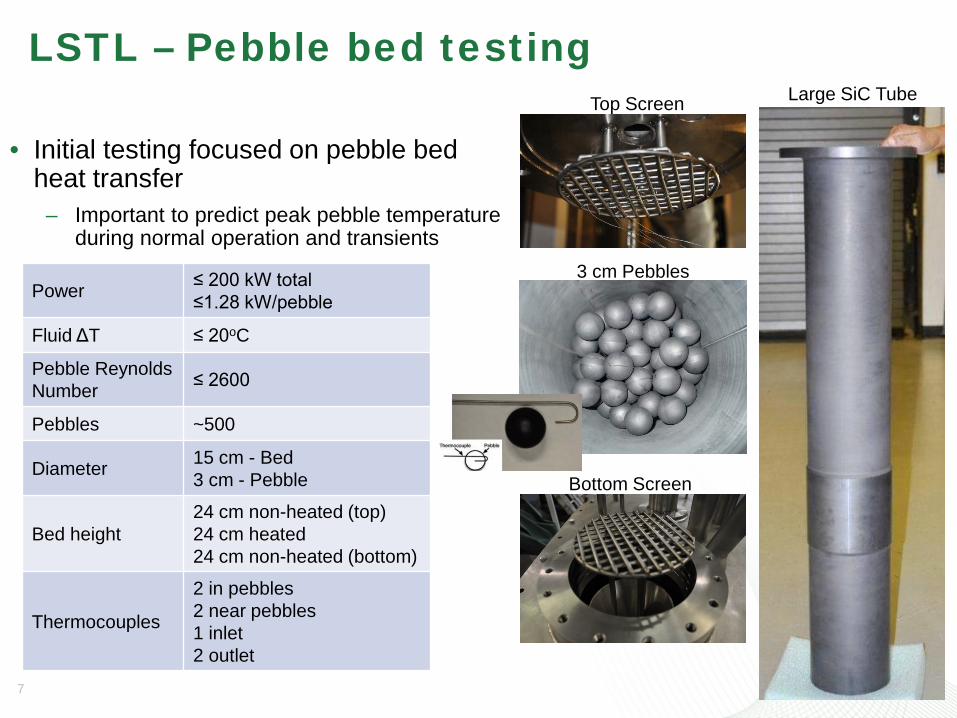
Power ≤ 200 kW total ≤1.28 kW/pebble
Fluid ΔT ≤ 20oC
Pebble Reynolds Number ≤ 2600
Pebbles ~500
Diameter 15 cm - Bed 3 cm - Pebble
Bed height 24 cm non-heated (top) 24 cm heated 24 cm non-heated (bottom)
Thermocouples
2 in pebbles 2 near pebbles 1 inlet 2 outlet
• Initial testing focused on pebble bed heat transfer
– Important to predict peak pebble temperature during normal operation and transients
LSTL – Pebble bed testing Large SiC Tube Top Screen
3 cm Pebbles
Bottom Screen

8
Component Development & Testing Pumps
• Objectives: – Characterize the performance of the existing pump – Improve impeller & volute design and test for
improvement – Develop selection & design guidance for salt pumps
• Status: – Using advanced simulation to aide impeller and
volute design – Developing cold shakedown test stand – FY16 3Q, modify LSTL to develop pump curves
• Collaborative R&D with SINAP
9
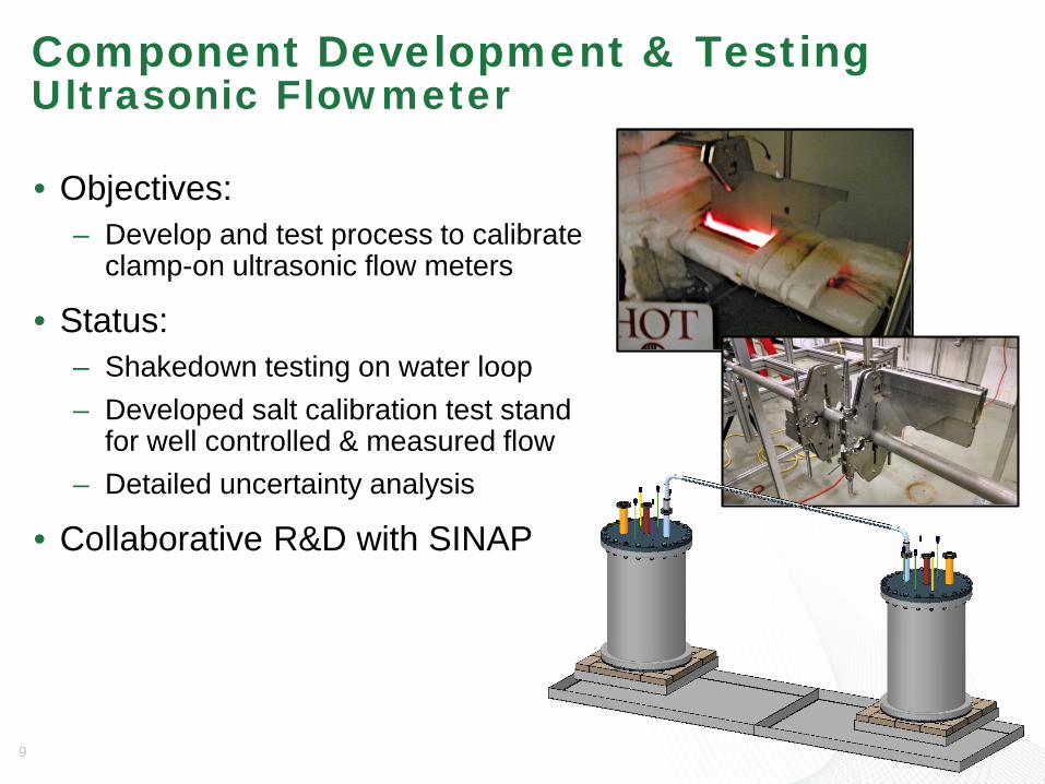
Component Development & Testing Ultrasonic Flowmeter
• Objectives: – Develop and test process to calibrate
clamp-on ultrasonic flow meters
• Status: – Shakedown testing on water loop – Developed salt calibration test stand
for well controlled & measured flow – Detailed uncertainty analysis
• Collaborative R&D with SINAP
10
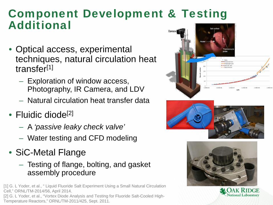
Component Development & Testing Additional
• Optical access, experimental techniques, natural circulation heat transfer[1]
– Exploration of window access, Photography, IR Camera, and LDV
– Natural circulation heat transfer data
• Fluidic diode[2] – A ‘passive leaky check valve’ – Water testing and CFD modeling
• SiC-Metal Flange – Testing of flange, bolting, and gasket
assembly procedure
[1] G. L Yoder, et al., “ Liquid Fluoride Salt Experiment Using a Small Natural Circulation Cell,” ORNL/TM-2014/56, April 2014. [2] G. L Yoder, et al., “Vortex Diode Analysis and Testing for Fluoride Salt-Cooled High-Temperature Reactors,” ORNL/TM-2011/425, Sept. 2011.

11
Salt Cleanup Facility
• Removes trace impurities from salt – Enabling facility for salt studies – Batch process, cleans 150 kg of salt in one week
• Significant capability – Uses HF, H2 and Ar – Large 2 m Nickel crucible
• Development supported by DOE-NE • Currently developing smaller
scale capability for Beryllium containing salts
12
Summary
• We need to address a variety of technology R&D and demonstration for reactor commercialization – Many common issues between FHR and MSR reactor classes
• The Liquid Salt Test Loop provides a versatile testing platform for a range of development needs – Planned testing includes shakedown, heat transfer, pump
performance, and corrosion tests – Future tests could include:
• Development: valve/seals, heat exchangers, etc. • Demonstration: advanced I&C, component endurance • Validation: tests for code benchmarks

13
Backup
14
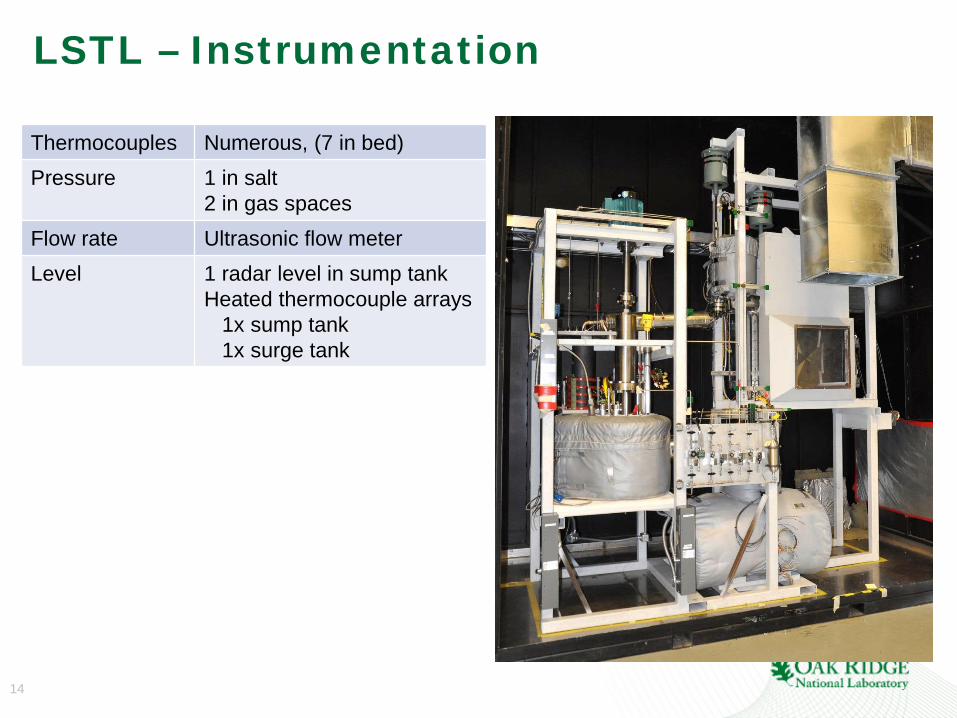
LSTL – Instrumentation
Thermocouples Numerous, (7 in bed) Pressure 1 in salt
2 in gas spaces Flow rate Ultrasonic flow meter Level 1 radar level in sump tank
Heated thermocouple arrays 1x sump tank 1x surge tank