orifice flangesemk24.ru/upload/files/wiki/standarts/asme b16.36_ed.2009.pdf · d. r. sharp, the...
TRANSCRIPT

Orifice Flanges
A N A M E R I C A N N A T I O N A L S T A N D A R D
ASME B16.36-2009(Revision of ASME B16.36-2006)
--``,`,,`,```,,,,,`,,```,,,,,`,-`-`,,`,,`,`,,`---

Металлопрокат и трубыпо стандартам
DIN, EN, ASTM
Поставляем металлопрокат по стандарту ASME B16.36
Стандарт предоставлен исключительно для ознакомления
Для заказа металлопрокатаили получения консультацииобращайтесь по следующим контактам:
Россия:
Беларусь:
Казахстан:
+7 (495) 134-41-64
+375 (29) 232-97-79
+7 (7172) 72-76-96
www.emk.bz [email protected]

Date of Issuance: November 4, 2009
The next edition of this Standard is scheduled for publication in 2014. There will be no addendaissued to this edition.
ASME issues written replies to inquiries concerning interpretations of technical aspects of thisStandard. Interpretations and errata are published on the ASME Web site under the Committee Pagesat http://cstools.asme.org as they are issued.
ASME is the registered trademark of The American Society of Mechanical Engineers.
This code or standard was developed under procedures accredited as meeting the criteria for American NationalStandards. The Standards Committee that approved the code or standard was balanced to assure that individuals fromcompetent and concerned interests have had an opportunity to participate. The proposed code or standard was madeavailable for public review and comment that provides an opportunity for additional public input from industry, academia,regulatory agencies, and the public-at-large.
ASME does not “approve,” “rate,” or “endorse” any item, construction, proprietary device, or activity.ASME does not take any position with respect to the validity of any patent rights asserted in connection with any
items mentioned in this document, and does not undertake to insure anyone utilizing a standard against liability forinfringement of any applicable letters patent, nor assume any such liability. Users of a code or standard are expresslyadvised that determination of the validity of any such patent rights, and the risk of infringement of such rights, isentirely their own responsibility.
Participation by federal agency representative(s) or person(s) affiliated with industry is not to be interpreted asgovernment or industry endorsement of this code or standard.
ASME accepts responsibility for only those interpretations of this document issued in accordance with the establishedASME procedures and policies, which precludes the issuance of interpretations by individuals.
No part of this document may be reproduced in any form,in an electronic retrieval system or otherwise,
without the prior written permission of the publisher.
The American Society of Mechanical EngineersThree Park Avenue, New York, NY 10016-5990
Copyright © 2009 byTHE AMERICAN SOCIETY OF MECHANICAL ENGINEERS
All rights reservedPrinted in U.S.A.
--``,`,,`,```,,,,,`,,```,,,,,`,-`-`,,`,,`,`,,`---

CONTENTS
Foreword . . . . . . . . . . . . . . . . . . . . . . . . . . . . . . . . . . . . . . . . . . . . . . . . . . . . . . . . . . . . . . . . . . . . . . . . . . . . . . ivCommittee Roster . . . . . . . . . . . . . . . . . . . . . . . . . . . . . . . . . . . . . . . . . . . . . . . . . . . . . . . . . . . . . . . . . . . . . vCorrespondence With the B16 Committee . . . . . . . . . . . . . . . . . . . . . . . . . . . . . . . . . . . . . . . . . . . . . . vi
1 Scope . . . . . . . . . . . . . . . . . . . . . . . . . . . . . . . . . . . . . . . . . . . . . . . . . . . . . . . . . . . . . . . . . . . . . . . . . . . . . 1
2 General . . . . . . . . . . . . . . . . . . . . . . . . . . . . . . . . . . . . . . . . . . . . . . . . . . . . . . . . . . . . . . . . . . . . . . . . . . . 1
3 Pressure–Temperature Ratings . . . . . . . . . . . . . . . . . . . . . . . . . . . . . . . . . . . . . . . . . . . . . . . . . . . . . . 1
4 Material . . . . . . . . . . . . . . . . . . . . . . . . . . . . . . . . . . . . . . . . . . . . . . . . . . . . . . . . . . . . . . . . . . . . . . . . . . . 1
5 Size. . . . . . . . . . . . . . . . . . . . . . . . . . . . . . . . . . . . . . . . . . . . . . . . . . . . . . . . . . . . . . . . . . . . . . . . . . . . . . . 2
6 Marking . . . . . . . . . . . . . . . . . . . . . . . . . . . . . . . . . . . . . . . . . . . . . . . . . . . . . . . . . . . . . . . . . . . . . . . . . . . 2
7 Flange Facing Finish . . . . . . . . . . . . . . . . . . . . . . . . . . . . . . . . . . . . . . . . . . . . . . . . . . . . . . . . . . . . . . . 2
8 Gaskets for Raised Face Flanges . . . . . . . . . . . . . . . . . . . . . . . . . . . . . . . . . . . . . . . . . . . . . . . . . . . . 2
9 Pressure Taps. . . . . . . . . . . . . . . . . . . . . . . . . . . . . . . . . . . . . . . . . . . . . . . . . . . . . . . . . . . . . . . . . . . . . . 2
10 Jack Screw Provision . . . . . . . . . . . . . . . . . . . . . . . . . . . . . . . . . . . . . . . . . . . . . . . . . . . . . . . . . . . . . . . 2
11 Flange Dimensions . . . . . . . . . . . . . . . . . . . . . . . . . . . . . . . . . . . . . . . . . . . . . . . . . . . . . . . . . . . . . . . . . 3
12 Flange Threads . . . . . . . . . . . . . . . . . . . . . . . . . . . . . . . . . . . . . . . . . . . . . . . . . . . . . . . . . . . . . . . . . . . . 3
13 Tolerances . . . . . . . . . . . . . . . . . . . . . . . . . . . . . . . . . . . . . . . . . . . . . . . . . . . . . . . . . . . . . . . . . . . . . . . . . 3
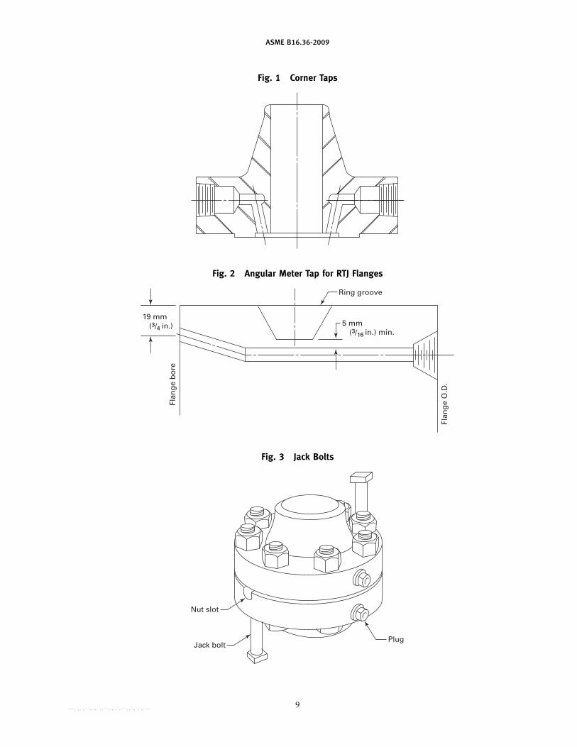
Figures1 Corner Taps . . . . . . . . . . . . . . . . . . . . . . . . . . . . . . . . . . . . . . . . . . . . . . . . . . . . . . . . . . . . . . . . . . . . . . 92 Angular Meter Tap for RTJ Flanges . . . . . . . . . . . . . . . . . . . . . . . . . . . . . . . . . . . . . . . . . . . . . . . 93 Jack Bolts . . . . . . . . . . . . . . . . . . . . . . . . . . . . . . . . . . . . . . . . . . . . . . . . . . . . . . . . . . . . . . . . . . . . . . . . 9
Tables1 Class 300 Orifice Flanges, Welding Neck, Threaded, and Slip-On . . . . . . . . . . . . . . . . . . . 42 Class 600 Orifice Flanges, Welding Neck . . . . . . . . . . . . . . . . . . . . . . . . . . . . . . . . . . . . . . . . . . 53 Class 900 Orifice Flanges, Welding Neck . . . . . . . . . . . . . . . . . . . . . . . . . . . . . . . . . . . . . . . . . . 64 Class 1500 Orifice Flanges, Welding Neck . . . . . . . . . . . . . . . . . . . . . . . . . . . . . . . . . . . . . . . . . 75 Class 2500 Orifice Flanges, Welding Neck . . . . . . . . . . . . . . . . . . . . . . . . . . . . . . . . . . . . . . . . . 8
Mandatory AppendicesI Dimensional Data for Classes 300, 600, 900, 1500, and 2500 Flanges in
U.S. Customary Units . . . . . . . . . . . . . . . . . . . . . . . . . . . . . . . . . . . . . . . . . . . . . . . . . . . . . . . . . . 11II Dimensional Data for Class 400 Flanges in U.S. Customary Units . . . . . . . . . . . . . . . . . . 17III References . . . . . . . . . . . . . . . . . . . . . . . . . . . . . . . . . . . . . . . . . . . . . . . . . . . . . . . . . . . . . . . . . . . . . . . . 19
Nonmandatory AppendixA Quality System Program . . . . . . . . . . . . . . . . . . . . . . . . . . . . . . . . . . . . . . . . . . . . . . . . . . . . . . . . . . 20
iii
--``,`,,`,```,,,,,`,,```,,,,,`,-`-`,,`,,`,`,,`---
FOREWORD
August of 1956 marked the first recorded correspondence noting the lack of standardizationfor orifice flanges. There were, and still are, several codes for the performance and calibrationof orifice flanges, but there had been no standardization of the flanges themselves. Over theensuing 3 years, correspondence continued among the Instrument Society of America, AmericanGas Association, and the B16 Standards Committee.
On December 3, 1959, Subcommittee 3 (now Subcommittee C) of B16 authorized the appoint-ment of a Task Force to undertake drafting of a standard. Although the initial work progressedsmoothly, a controversy developed over the standard size of taps to be specified for the flanges.This required many years to resolve. It was finally achieved in 1973 with the issuance of a draftfrom the Task Force. Comments and objections to this draft from members of Subcommittee Cwere resolved, and a redraft was approved by the Subcommittee late in 1974. The B16 StandardsCommittee was balloted in the spring of 1975 and approval was gained. Comments from B16members from the gas industry requested that the Class 400 orifice flange be included, and theB16 Subcommittee C agreed to consider this for a possible addendum. The Standard was approvedby ANSI on August 15, 1975.
On April 30, 1979, an addenda was issued, which added Class 400 flanges andMandatory Appendix II covering reference documents and organizations.
In 1982, American National Standards Committee B16 was reorganized as an ASME Committeeoperating under procedures accredited by ANSI. In the 1988 edition, figures were added toillustrate jack bolts and corner taps, metric units have been omitted, and references to otherstandards have been updated. Following approval by the B16 Main Committee and the ASMESupervisory Board, the Standard was approved as an American National Standard by ANSI onFebruary 18, 1988.
In 1996, several revisions were made, including the addition of angular meter taps for ringjoint flanges in sizes not previously covered. Following approval by the B16 Main Committeeand the ASME Supervisory Board, the Standard was approved as an American National Standardby ANSI on November 6, 1996.
In 2006, several revisions were made, including the use of metric units as the primary referenceunits, while maintaining U.S. Customary units in either parenthetical or separate forms. Changesto dimensions and nomenclature followed that were contained within the 2003 edition ofASME B16.5. This includes the change of minimum flange thickness from C to tf and correctionsfor Y1 and Y2. Class 400 remains in U.S. Customary tables in Mandatory Appendix II, but is notgiven in the metric dimensional tables. There are numerous requirement clarifications and editorialrevisions. Following the approvals of the Standards Committee and ASME, approval for the newedition was granted by the American National Standards Institute on November 6, 2006.
In the 2009 edition, Mandatory Appendix III was revised and updated. Also, section 4, thematerials section, has been revised to cover requirements of material specification editions otherthan those listed in Appendix III of ASME B16.5.
Requests for interpretations or suggestions for revisions should be sent to the Secretary,B16 Committee, Three Park Avenue, New York, NY 10016-5990. As an alternative, inquiries maybe submitted via e-mail to: [email protected].
This revision was approved by the American National Standards Institute on August 13, 2009.
iv--``,`,,`,```,,,,,`,,```,,,,,`,-`-`,,`,,`,`,,`---

ASME B16 COMMITTEEStandardization of Valves, Flanges,
Fittings, and Gaskets(The following is the roster of the Committee at the time of approval of this Standard.)
STANDARDS COMMITTEE OFFICERS
W. B. Bedesem, ChairM. L. Nayyar, Vice Chair
D. R. Sharp, Secretary
STANDARDS COMMITTEE PERSONNEL
R. W. Barnes, ANRIC Enterprises, Inc.W. B. Bedesem, ExxonMobil Research & Engineering Co.D. F. Buccicone, Elkhart Products Corp.A. M. Cheta, Shell Westhollow Technology CenterM. A. Clark, NIBCO, Inc.G. A. Cuccio, Capital Manufacturing Co.C. E. Davila, Crane ValvesC. E. Floren, Mueller Co.D. R. Frikken, Becht Engineering Co.R. P. Griffiths, U.S. Coast GuardM. L. Henderson, TIEC, Inc.
SUBCOMMITTEE C — STEEL FLANGES AND FLANGED FITTINGS
C. E. Davila, Chair, Crane ValvesA. P. Maslowski, Secretary, The American Society of Mechanical
EngineersA. Appleton, Alloy Stainless Products Co., Inc.W. B. Bedesem, ExxonMobil Research & Engineering Co.A. M. Cheta, Shell Westhollow Technology CenterB. Dennis, Kerkau ManufacturingJ. P. Ellenberger, ConsultantD. R. Frikken, Becht Engineering Co.M. L. Henderson, TIEC, Inc.
v
G. A. Jolly, Vogt Valves/FlowserveM. Katcher, Haynes InternationalW. N. McLean, B & L EngineeringT. A. McMahon, Fisher Controls International, Inc.M. L. Nayyar, Bechtel Power Corp.J. D. Page, U.S. Nuclear Regulatory CommissionW. H. Patrick, The Dow Chemical Co.R. A. Schmidt, Hackney Ladish, Inc.D. R. Sharp, The American Society of Mechanical EngineersH. R. Sonderegger, Anvil International, Inc.W. M. Stephan, Flexitallic LPD. A. Williams, Southern Company Services
C. L. Henley, Black & VeatchR. E. Johnson, ConsultantM. Katcher, Haynes InternationalW. N. McLean, B & L EngineeringM. L. Nayyar, Bechtel Power Corp.W. H. Patrick, The Dow Chemical Co.T. V. Ramakrishnan, Forged Vessel ConnectionsR. A. Schmidt, Hackney Ladish, Inc.J. P. Tucker, FlowserveM. M. Zaidi, Jacobs
--``,`,,`,```,,,,,`,,```,,,,,`,-`-`,,`,,`,`,,`---

CORRESPONDENCE WITH THE B16 COMMITTEE
General. ASME Standards are developed and maintained with the intent to represent theconsensus of concerned interests. As such, users of this Standard may interact with the Committeeby requesting interpretations, proposing revisions, and attending Committee meetings. Corre-spondence should be addressed to:
Secretary, B16 Standards CommitteeThe American Society of Mechanical EngineersThree Park AvenueNew York, NY 10016-5990
As an alternative, inquiries may be submitted via e-mail to: [email protected] Revisions. Revisions are made periodically to the Standard to incorporate changes
that appear necessary or desirable, as demonstrated by the experience gained from the applicationof the Standard. Approved revisions will be published periodically.
The Committee welcomes proposals for revisions to this Standard. Such proposals should beas specific as possible, citing the paragraph number(s), the proposed wording, and a detaileddescription of the reasons for the proposal, including any pertinent documentation.
Interpretations. Upon request, the B16 Committee will render an interpretation of any require-ment of the Standard. Interpretations can only be rendered in response to a written request sentto the Secretary of the B16 Standards Committee.
The request for interpretation should be clear and unambiguous. It is further recommendedthat the inquirer submit his/her request in the following format:
Subject: Cite the applicable paragraph number(s) and the topic of the inquiry.Edition: Cite the applicable edition of the Standard for which the interpretation is
being requested.Question: Phrase the question as a request for an interpretation of a specific requirement
suitable for general understanding and use, not as a request for an approvalof a proprietary design or situation. The inquirer may also include any plansor drawings, which are necessary to explain the question; however, theyshould not contain proprietary names or information.
Requests that are not in this format will be rewritten in this format by the Committee priorto being answered, which may inadvertently change the intent of the original request.
ASME procedures provide for reconsideration of any interpretation when or if additionalinformation that might affect an interpretation is available. Further, persons aggrieved by aninterpretation may appeal to the cognizant ASME Committee or Subcommittee. ASME does not“approve,” “certify,” “rate,” or “endorse” any item, construction, proprietary device, or activity.
Attending Committee Meetings. The B16 Standards Committee regularly holds meetings, whichare open to the public. Persons wishing to attend any meeting should contact the Secretary ofthe B16 Standards Committee.
vi--``,`,,`,```,,,,,`,,```,,,,,`,-`-`,,`,,`,`,,`---
ASME B16.36-2009
ORIFICE FLANGES
1 SCOPE
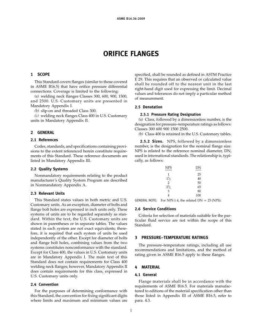
This Standard covers flanges (similar to those coveredin ASME B16.5) that have orifice pressure differentialconnections. Coverage is limited to the following:
(a) welding neck flanges Classes 300, 600, 900, 1500,and 2500. U.S. Customary units are presented inMandatory Appendix I.
(b) slip-on and threaded Class 300.(c) welding neck flanges Class 400 in U.S. Customary
units in Mandatory Appendix II.
2 GENERAL
2.1 References
Codes, standards, and specifications containing provi-sions to the extent referenced herein constitute require-ments of this Standard. These reference documents arelisted in Mandatory Appendix III.
2.2 Quality Systems
Nonmandatory requirements relating to the productmanufacturer’s Quality System Program are describedin Nonmandatory Appendix A.
2.3 Relevant Units
This Standard states values in both metric and U.S.Customary units. As an exception, diameter of bolts andflange bolt holes are expressed in inch units only. Thesesystems of units are to be regarded separately as stan-dard. Within the text, the U.S. Customary units areshown in parentheses or in separate tables. The valuesstated in each system are not exact equivalents; there-fore, it is required that each system of units be usedindependently of the other. Except for diameter of boltsand flange bolt holes, combining values from the twosystems constitutes nonconformance with the standard.Except for Class 400, the values in U.S. Customary unitsare in Mandatory Appendix I. The main text of thisStandard does not contain requirements for Class 400welding neck flanges; however, Mandatory Appendix IIdoes contain requirements for this class, expressed inU.S. Customary units only.
2.4 Convention
For the purposes of determining conformance withthis Standard, the convention for fixing significant digitswhere limits and maximum and minimum values are
1
specified, shall be rounded as defined in ASTM PracticeE 29. This requires that an observed or calculated valueshall be rounded off to the nearest unit in the lastright-hand digit used for expressing the limit. Decimalvalues and tolerances do not imply a particular methodof measurement.
2.5 Denotation
2.5.1 Pressure Rating Designation(a) Class, followed by a dimensionless number, is the
designation for pressure–temperature ratings as follows:Classes 300 600 900 1500 2500.
(b) Class 400 is retained in the U.S. Customary tables.
2.5.2 Sizes. NPS, followed by a dimensionlessnumber, is the designation for the nominal flange size.NPS is related to the reference nominal diameter, DN,used in international standards. The relationship is, typi-cally, as follows:
NPS DN
1 2511⁄2 402 50
21⁄2 653 804 100
GENERAL NOTE: For NPS ≥ 4, the related DN p 25 (NPS).
2.6 Service Conditions
Criteria for selection of materials suitable for the par-ticular fluid service are not within the scope of thisStandard.
3 PRESSURE–TEMPERATURE RATINGS
The pressure–temperature ratings, including all userecommendations and limitations, and the method ofrating given in ASME B16.5 apply to these flanges.
4 MATERIAL
4.1 General
Flange materials shall be in accordance with therequirements of ASME B16.5. For materials manufac-tured to editions of the material specification other thanthose listed in Appendix III of ASME B16.5, refer topara. 4.3.
--``,`,,`,```,,,,,`,,```,,,,,`,-`-`,,`,,`,`,,`---

ASME B16.36-2009
4.2 Bolting
Bolting material recommendations are given inASME B16.5. For materials manufactured to editionsof the material specification other than those listed inAppendix III of ASME B16.5, refer to para. 4.3.
4.3 Materials Manufactured to Other Editions
Materials may meet the requirements of material spec-ification editions other than those listed in Appendix IIIof ASME B16.5, provided
(a) the materials are the same specification, e.g.,grade, type, class, or alloy, and heat-treated conditions,as applicable
(b) the flange manufacturer certifies that the require-ments of the edition of the specification listed inAppendix III of ASME B16.5 have been met
4.4 Plugs
Pressure-retaining plugs shall conform toASME B16.11, unless otherwise agreed between pur-chaser and manufacturer. Plug material shall be at leastas corrosion resistant as the corresponding flangematerial.
5 SIZE
Orifice flange sizes are indicated by the nominal pipesize to which they are attached. Only those listed inTables 1 through 5, Tables I-1 through I-5, andMandatory Appendix II are considered standard.
6 MARKING
Flanges shall be marked as required in ASME B16.5.For welding neck flanges only, the bore diameter shallbe marked.
7 FLANGE FACING FINISH
The finish of contact faces shall conform to the require-ments of ASME B16.5.
8 GASKETS FOR RAISED FACE FLANGES
8.1 Gasket Thickness
Flange dimensions are based on the use of 1.5 mm(0.06 in.) thick gaskets.
8.2 Flange Gaskets Requiring Dimensional Changes
When the location of the pressure tap with respect tothe orifice plate is critical to the service and meteringconditions, its location may be altered to accommodateother than 1.5 mm (0.06 in.) thick gaskets or ring-typejoint gaskets whose thickness may vary from that listedin Tables 2, 3, 4, and 5 or those listed in Tables I-2, I-3,I-4, and I-5 or Mandatory Appendix II.
2
The alteration of location may also be accomplishedby the removal of 2 mm (0.06 in.) from the raised faceof the flange. If an original 2 mm (0.06 in.) high raisedface is removed, the user is cautioned to limit the outsidediameter of the gasket or orifice plate to the tabulatedR dimension.
9 PRESSURE TAPS
9.1 General
Each orifice flange shall be provided with two pres-sure tap holes extending radially from the outside diam-eter of the flange to the inside diameter of the flange.Corner taps may be used on NPS 11⁄2 and smaller ifspace permits. See Fig. 1.
For ring joint flanges listed in Tables 2 through 5,Tables I-1 through I-5, and Mandatory Appendix II,where radial taps will interfere with the ring groove,angular meter taps, as illustrated in Fig. 2, will berequired. Each pressure tap hole shall be equipped witha pipe plug.
9.2 Location
9.2.1 Measurement. The 24 mm (0.94 in.) dimensionfor raised face and 19 mm (0.75 in.) for ring joint shallbe measured at the bore.
9.2.2 Identification. For ring joint flanges requiringalteration of pressure tap location due to interferencewith the ring groove other than methods provided inthis Standard, such alteration shall be identified peragreement between purchaser and manufacturer.
9.3 Pipe Connection
Unless otherwise specified, pressure tap holes may beeither tapped 1⁄2 NPT in accordance with ASME B1.20.1or 1⁄2 NPS socket connection in accordance withASME B16.11.
10 JACK SCREW PROVISION
10.1 Location
Each flange shall have a machine bolt mounted in ahole drilled on the flange bolt circle centerline at 90 degfrom the pressure taps, for use as a jack screw. Themachine bolt shall be regular with one heavy hex nut.See Fig. 3.
10.2 Slot for Nut
A slot shall be provided in the flange 2 mm (0.06 in.)wider than the width across flats of the nut. The depth ofthe slot shall admit the nut so that there is no interferencewith the joining of the flanges when bolted togetherwithout orifice plate.

ASME B16.36-2009
10.3 Tapped Hole
As an alternative to para. 10.2, a tapped hole maybe provided and the hex nut omitted when agreed onbetween the purchaser and the manufacturer.
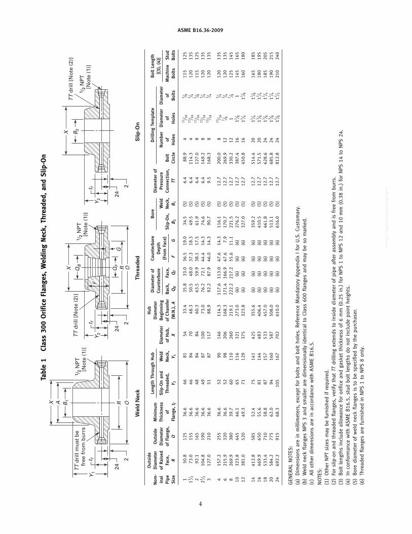
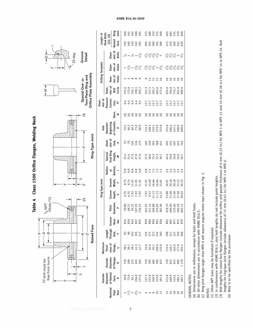
11 FLANGE DIMENSIONS
Dimensions are listed in Tables 1, 2, 3, 4, and 5 formetric, and Tables I-1, I-2, I-3, I-4, and I-5, andMandatory Appendix II for U.S. Customary.
12 FLANGE THREADS
Threaded flanges shall have an American NationalStandard taper pipe thread conforming toASME B1.20.1.
(a) The thread shall be concentric with the axis of theflange. Variations in alignment shall not exceed 5 mm/m(0.06 in./ft).
(b) The flanges are made with counterbores at theback of the flange and the threads shall be chamferedto the diameter of the counterbore at an angle of approxi-mately 45 deg with the axis of the thread to afford easyentrance in making a joint. The counterbore and chamfershall be concentric with the thread.
(c) In order to permit the pipe to be inserted to theface of the flange, the threads should have full root
3
diameters through to the face of the flange, or shall havea counterbore at the face of the flange.
(d) The gaging notch of the working gage shall comeflush with the bottom of the chamfer in all threadedflanges and shall be considered as being the intersectionof the chamfer cone and the pitch cone of the thread.This depth of chamfer is approximately equal to one-halfthe pitch of the thread.
(e) The maximum allowable thread variation is oneturn large or small from the gaging notch.
13 TOLERANCES
Tolerances on all dimensions shall be as shown inASME B16.5 except for those shown below.
13.1 Pressure Tap Location
Tolerance on location of center of pressure tap hole1
from flange face shall be(a) ±0.5 mm (±0.02 in.) for flanges smaller than NPS 4(b) ±0.8 mm (±0.03 in.) for flanges NPS 4 and larger
13.2 Bore Diameter
Bore diameter tolerance (welding neck flanges only)is ±0.5% of nominal value.
1 See para. 9.2.
--``,`,,`,```,,,,,`,,```,,,,,`,-`-`,,`,,`,`,,`---
ASME B16.36-2009
Tabl
e1
Clas
s30
0O
rific
eFl
ange
s,W
eldi
ngN
eck,
Thre
aded
,an
dS
lip-O
n
2
24
B1
TT
dri
ll m
ust
be
fr
ee f
rom
bu
rrs
TT
dri
ll [N
ote
(2)
]
t fY
1
A R O
We
ld N
eck
X
1 /2
NP
T
[No
te (
1)]
1 /2
NP
T
[No
te (
1)]
Y2
X QB
QF R
G
O
Th
rea
de
dS
lip
-On
t f 2
24
TT
dri
ll [N
ote
(2)
]
1 /2
NP
T
[No
te (
1)]
X B2
Y2
t f 2
24
F
Out
side
Hub
Leng
thTh
roug
hH
ubD
iam
eter
ofCo
unte
rbor
eB
ore
Dri
lling
Tem
plat
eB
olt
Leng
thN
om-
Dia
met
erO
utsi
deM
inim
umD
iam
eter
Dia
met
erof
Coun
terb
ore
Dep
th[(
3),
(4)]
inal
ofR
aise
dD
iam
eter
Thic
knes
sS
lip-O
nan
dW
eld
Dia
met
erB
egin
ning
Wel
dPr
essu
reN
umbe
rD
iam
eter
Dia
met
er(F
rom
Face
)Pi
peFa
ce,
ofFl
ange
,of
Thre
aded
,N
eck,
ofH
ub,
ofCh
amfe
rB
ack,
Face
,S
lip-O
n,N
eck,
Conn
ecti
on,
Bol
tof
ofof
Mac
hine
Stu
dS
ize
RO
Flan
ge,
t fY 2
Y 1X
(W.N
.),
AQ
BQ
FF
GB
2B
1TT
Circ
leH
oles
Hol
esB
olts
Bol
tsB
olts
150
.812
536
.646
8154
33.4
35.8
33.0
36.5
19.0
34.5
(5)
6.4
88.9
411
⁄ 16
5 ⁄ 811
512
511 ⁄ 2
73.0
155
36.6
4684
7048
.350
.548
.037
.318
.349
.5(5
)6.
411
4.3
413
⁄ 16
3 ⁄ 412
013
52
92.1
165
36.6
4884
8460
.363
.559
.938
.117
.561
.9(5
)6.
412
7.0
811
⁄ 16
5 ⁄ 811
512
521 ⁄ 2
104.
819
036
.649
8710
073
.076
.272
.144
.414
.374
.6(5
)6.
414
9.2
813
⁄ 16
3 ⁄ 412
013
53
127.
021
036
.651
8711
788
.992
.287
.946
.014
.390
.7(5
)9.
516
8.3
813
⁄ 16
3 ⁄ 412
013
5
415
7.2
255
36.6
5290
146
114.
311
7.6
113.
047
.614
.311
6.1
(5)
12.7
200.
08
13⁄ 1
63 ⁄ 4
120
135
621
5.9
320
36.6
5298
206
168.
317
1.4
166.
947
.67.
917
0.7
(5)
12.7
269.
912
7 ⁄ 83 ⁄ 4
120
135
826
9.9
380
39.7
6011
026
021
9.1
222.
221
7.2
55.6
11.1
221.
5(5
)12
.733
0.2
121
7 ⁄ 812
514
510
323.
844
546
.165
116
321
273.
0(6
)(6
)(6
)(6
)27
6.2
(5)
12.7
387.
416
11 ⁄ 81
145
165
1238
1.0
520
49.3
7112
937
532
3.8
(6)
(6)
(6)
(6)
327.
0(5
)12
.745
0.8
1611 ⁄ 4
11 ⁄ 816
018
0
1441
2.8
585
52.4
7514
142
535
5.6
(6)
(6)
(6)
(6)
359.
2(5
)12
.751
4.4
2011 ⁄ 4
11 ⁄ 816
518
516
469.
965
055
.681
144
483
406.
4(6
)(6
)(6
)(6
)41
0.5
(5)
12.7
571.
520
13 ⁄ 811 ⁄ 4
180
195
1853
3.4
710
58.8
8715
753
345
7.0
(6)
(6)
(6)
(6)
461.
8(5
)12
.762
8.6
2413 ⁄ 8
11 ⁄ 418
520
520
584.
277
562
.094
160
587
508.
0(6
)(6
)(6
)(6
)51
3.1
(5)
12.7
685.
824
13 ⁄ 811 ⁄ 4
190
215
2469
2.2
915
68.3
105
167
702
610.
0(6
)(6
)(6
)(6
)61
6.0
(5)
12.7
812.
824
15 ⁄ 811 ⁄ 2
210
240
GEN
ERA
LN
OTE
S:
(a)
Dim
ensi
ons
are
inm
illim
eter
s,ex
cept
for
bolt
san
dbo
ltho
les.
Refe
renc
eM
anda
tory
App
endi
xI
for
U.S
.Cu
stom
ary.
(b)
Wel
dne
ckfla
nges
NPS
3an
dsm
alle
rar
edi
men
sion
ally
iden
tica
lto
Clas
s60
0fla
nges
and
may
beso
mar
ked.
(c)
All
othe
rdi
men
sion
sar
ein
acco
rdan
cew
ith
ASM
EB
16.5
.
NO
TES
:(1
)O
ther
NPT
size
sm
aybe
furn
ishe
dif
requ
ired
.(2
)Fo
rsl
ip-o
nan
dth
read
edfla
nges
,ve
rify
that
TTdr
illin
gex
tend
sto
insi
dedi
amet
erof
pipe
afte
ras
sem
bly
and
isfr
eefr
ombu
rrs.
(3)
Bol
tle
ngth
sin
clud
eal
low
ance
for
orifi
cean
dga
sket
thic
knes
sof
6m
m(0
.25
in.)
for
NPS
1to
NPS
12an
d10
mm
(0.3
8in
.)fo
rN
PS14
toN
PS24
.(4
)In
conf
orm
ance
wit
hA
SME
B16
.5,
stud
bolt
leng
ths
dono
tin
clud
epo
int
heig
hts.
(5)
Bor
edi
amet
erof
wel
dne
ckfla
nges
isto
besp
ecifi
edby
the
purc
hase
r.(6
)Th
read
edfla
nges
are
furn
ishe
din
NPS
1to
NPS
8on
ly.
4
--``,`,,`,```,,,,,`,,```,,,,,`,-`-`,,`,,`,`,,`---

ASME B16.36-2009
Tabl
e2
Clas
s60
0O
rific
eFl
ange
s,W
eldi
ngN
eck
24
B
TT
dri
ll m
ust
be
fr
ee f
rom
bu
rrs
t fH
Y
A
Ra
ise
d F
ace
Rin
g-T
yp
e J
oin
t
Sp
ecia
l O
ne
- o
r
Tw
o-P
iece
Rin
g
an
d O
rifi
ce
Pla
te A
sse
mb
ly
Gro
ov
e
De
tail
X1 /
2 N
PT
[N
ote
(1)
]
OR19
23 d
eg
t fEY
P
F
E
r
W
Out
side
Dri
lling
Tem
plat
eR
ing-
Type
Join
tLe
ngth
ofD
iam
eter
Hei
ght
Dia
m-
Hub
Dia
m-
Dia
met
erof
Stu
dB
olts
ofO
utsi
deM
inim
umLe
ngth
ofS
peci
alet
erD
iam
eter
eter
ofN
um-
Dia
m-
Hol
es[(
2),
(3)]
Nom
inal
Rai
sed
Dia
met
erTh
ick-
Thro
ugh
Rai
sed
Gro
ove
Pitc
hG
roov
eG
roov
eR
adiu
sat
Ova
lR
ing
ofB
egin
ning
Pres
sure
ber
eter
Pipe
Face
,of
Flan
ge,
ness
ofH
ub,
Face
,N
um-
Dia
met
er,
Dep
th,
Wid
th,
Bot
tom
,H
eigh
t,H
ub,
ofCh
amfe
r,B
ore,
Conn
ec-
Bol
tof
Rai
sed
Rin
gof
Rai
sed
Rin
gS
ize
RO
Flan
ge,
t fY
Hbe
rP
EF
rW
XA
Bti
on,
TTCi
rcle
Hol
esFa
ceJo
int
Bol
tsFa
ceJo
int
150
.812
536
.681
2R1
650
.80
6.35
8.74
0.8
25.4
5433
.5(4
)6.
488
.94
11⁄ 1
63 ⁄ 4
5 ⁄ 812
514
011 ⁄ 2
73.0
155
36.6
842
R20
68.2
76.
358.
740.
825
.470
48.3
(4)
6.4
114.
34
13⁄ 1
67 ⁄ 8
3 ⁄ 413
514
02
92.1
165
36.6
842
R23
82.5
57.
9211
.91
0.8
27.0
8460
.3(4
)6.
412
7.0
811
⁄ 16
3 ⁄ 45 ⁄ 8
125
140
21 ⁄ 210
4.8
190
36.6
872
R26
101.
607.
9211
.91
0.8
27.0
100
73.0
(4)
6.4
149.
28
13⁄ 1
67 ⁄ 8
3 ⁄ 413
514
53
127.
021
036
.687
2R3
112
3.83
7.92
11.9
10.
827
.011
788
.9(4
)9.
516
8.3
813
⁄ 16
7 ⁄ 83 ⁄ 4
135
145
415
7.2
275
38.1
102
7R3
714
9.23
7.92
11.9
10.
827
.015
211
4.3
(4)
12.7
215.
98
11
7 ⁄ 815
016
56
215.
935
547
.711
77
R45
211.
127.
9211
.91
0.8
27.0
222
168.
3(4
)12
.729
2.1
1211 ⁄ 8
11 ⁄ 81
180
190
826
9.9
420
55.6
133
7R4
926
9.88
7.92
11.9
10.
827
.027
321
9.1
(4)
12.7
349.
212
11 ⁄ 411 ⁄ 4
11 ⁄ 819
521
010
323.
851
063
.515
27
R53
323.
857.
9211
.91
0.8
27.0
343
273.
0(4
)12
.743
1.8
1613 ⁄ 8
13 ⁄ 811 ⁄ 4
220
235
1238
1.0
560
66.7
156
7R5
738
1.00
7.92
11.9
10.
827
.040
032
3.8
(4)
12.7
489.
020
13 ⁄ 813 ⁄ 8
11 ⁄ 423
024
0
1441
2.8
605
69.9
165
7R6
141
9.10
7.92
11.9
10.
827
.043
235
5.6
(4)
12.7
527.
020
11 ⁄ 211 ⁄ 2
13 ⁄ 824
025
516
469.
968
576
.217
87
R65
469.
907.
9211
.91
0.8
30.2
495
406.
4(4
)12
.760
3.2
2015 ⁄ 8
15 ⁄ 811 ⁄ 2
260
275
1853
3.4
745
82.6
184
7R6
953
3.40
7.92
11.9
10.
830
.254
645
7.2
(4)
12.7
654.
020
13 ⁄ 413 ⁄ 4
15 ⁄ 828
029
020
584.
281
588
.919
07
R73
584.
209.
5313
.49
1.5
31.8
610
508.
0(4
)12
.772
3.9
2413 ⁄ 4
13 ⁄ 415 ⁄ 8
300
320
2469
2.2
940
101.
620
37
R77
692.
1511
.13
16.6
61.
536
.571
860
9.6
(4)
12.7
838.
224
22
17 ⁄ 833
535
0
GEN
ERA
LN
OTE
S:
(a)
Dim
ensi
ons
are
inm
illim
eter
s,ex
cept
for
bolt
san
dbo
ltho
les.
Refe
renc
eM
anda
tory
App
endi
xI
for
U.S
.Cu
stom
ary.
(b)
Wel
dne
ckfla
nges
NPS
3an
dsm
alle
rar
eid
enti
cal
toCl
ass
300
flang
esex
cept
for
bolt
ing
and
may
beus
edfo
rsu
chse
rvic
e.(c
)A
llot
her
dim
ensi
ons
are
inac
cord
ance
wit
hA
SME
B16
.5.
(d)
Ring
join
tfla
nge
inN
PS24
will
requ
ire
anan
gula
rm
eter
tap
assh
own
inFi
g.2.
NO
TES
:(1
)O
ther
NPT
size
sm
aybe
furn
ishe
dif
requ
ired
.(2
)In
conf
orm
ance
wit
hA
SME
B16
.5,
stud
bolt
leng
ths
dono
tin
clud
epo
int
heig
hts.
(3)
Bol
tle
ngth
sfo
rra
ised
face
flang
esin
clud
eal
low
ance
for
orifi
cean
dga
sket
thic
knes
sof
6m
m(0
.25
in.)
for
NPS
1to
NPS
12an
d10
mm
(0.3
8in
.)fo
rN
PS14
toN
PS24
.B
olt
leng
ths
for
ring
-typ
ejo
int
flang
esin
clud
eal
low
ance
of15
mm
(0.6
2in
.)fo
rN
PS1
toN
PS10
,19
mm
(0.7
5in
.)fo
rN
PS12
toN
PS18
,an
d22
mm
(0.8
8in
.)fo
rN
PS20
.(4
)B
ore
isto
besp
ecifi
edby
the
purc
hase
r.
5 --``,`,,`,```,,,,,`,,```,,,,,`,-`-`,,`,,`,`,,`---

ASME B16.36-2009
Tabl
e3
Clas
s90
0O
rific
eFl
ange
s,W
eldi
ngN
eck
24
B
TT
dri
ll m
ust
be
fr
ee f
rom
bu
rrs
t f7
Y
A
Ra
ise
d F
ace
Rin
g-T
yp
e J
oin
t
Sp
ecia
l O
ne
- o
r
Tw
o-P
iece
Rin
g a
nd
Ori
fice
Pla
te A
sse
mb
ly
Gro
ov
e
De
tail
X1 /
2 N
PT
[N
ote
(1)
]
OR19
23 d
eg
t fEY
P
F
E
r
W
Dia
m-
Rin
g-Ty
peJo
int
Dri
lling
Tem
plat
eLe
ngth
ofO
utsi
deM
inim
umH
ubet
erof
Stu
dB
olts
Dia
met
erO
utsi
deTh
ick-
Leng
thR
adiu
sS
peci
alD
iam
-D
iam
eter
Pres
sure
Dia
m-
[(2)
,(3
)]N
omin
alof
Rai
sed
Dia
met
erne
ssof
Thro
ugh
Gro
ove
Pitc
hG
roov
eG
roov
eat
Ova
lR
ing
eter
ofB
egin
ning
Conn
ec-
eter
ofN
um-
Dia
m-
Dia
m-
Pipe
Face
,of
Flan
ge,
Flan
ge,
Hub
,N
um-
Dia
met
er,
Dep
th,
Wid
th,
Bot
tom
,H
eigh
t,H
ub,
ofCh
amfe
r,B
ore,
tion
,B
olt
ber
ofet
erof
eter
ofR
aise
dR
ing
Siz
eR
Ot f
Ybe
rP
EF
rW
XA
BTT
Circ
leH
oles
Hol
esB
olts
Face
Join
t
1 11 ⁄ 2 2Fo
rN
PS21 ⁄ 2
and
smal
ler,
use
Clas
s15
00.
21 ⁄ 2 312
7.0
240
38.1
102
R31
123.
837.
9211
.91
0.8
27.0
127
88.9
(4)
9.5
190.
58
17 ⁄ 8
150
165
415
7.2
290
44.5
114
R37
149.
237.
9211
.91
0.8
27.0
159
114.
3(4
)12
.723
5.0
811 ⁄ 4
11 ⁄ 818
019
06
215.
938
055
.614
0R4
521
1.12
7.92
11.9
10.
827
.023
516
8.3
(4)
12.7
317.
512
11 ⁄ 411 ⁄ 8
195
210
826
9.9
470
63.5
162
R49
269.
887.
9211
.91
0.8
27.0
298
219.
1(4
)12
.739
3.7
1211 ⁄ 2
13 ⁄ 823
024
010
323.
854
569
.918
4R5
332
3.85
7.92
11.9
10.
827
.036
827
3.0
(4)
12.7
469.
916
11 ⁄ 213 ⁄ 8
240
255
1238
1.0
610
79.4
200
R57
381.
007.
9211
.91
0.8
27.0
419
323.
8(4
)12
.753
3.4
2011 ⁄ 2
13 ⁄ 826
027
5
1441
2.8
640
85.8
213
R62
419.
1011
.13
16.6
61.
533
.345
135
5.6
(4)
12.7
558.
820
15 ⁄ 811 ⁄ 2
280
290
1646
9.9
705
88.9
216
R66
469.
9011
.13
16.6
61.
536
.550
840
6.4
(4)
12.7
616.
020
13 ⁄ 415 ⁄ 8
290
305
1853
3.4
785
101.
622
9R7
053
3.40
12.7
019
.84
1.5
39.7
565
457.
2(4
)12
.768
5.8
202
17 ⁄ 833
035
020
584.
285
510
8.0
248
R74
584.
2012
.70
19.8
41.
539
.762
250
8.0
(4)
12.7
749.
320
21 ⁄ 82
355
375
2469
2.2
104
013
9.7
292
R78
692.
1515
.88
26.9
72.
447
.674
960
9.6
(4)
12.7
901.
720
25 ⁄ 821 ⁄ 2
445
470
GEN
ERA
LN
OTE
S:
(a)
Dim
ensi
ons
are
inm
illim
eter
s,ex
cept
for
bolt
san
dbo
ltho
les.
Refe
renc
eM
anda
tory
App
endi
xI
for
U.S
.Cu
stom
ary.
(b)
All
othe
rdi
men
sion
sar
ein
acco
rdan
cew
ith
ASM
EB
16.5
.(c
)Ri
ngjo
int
flang
esla
rger
than
NPS
12w
illre
quir
ean
gula
rm
eter
taps
assh
own
inFi
g.2.
NO
TES
:(1
)O
ther
NPT
size
sm
aybe
furn
ishe
dif
requ
ired
.(2
)In
conf
orm
ance
wit
hA
SME
B16
.5,
stud
bolt
leng
ths
dono
tin
clud
epo
int
heig
hts.
(3)
Bol
tle
ngth
sfo
rra
ised
face
flang
esin
clud
eal
low
ance
for
orifi
cean
dga
sket
thic
knes
sof
6m
m(0
.25
in.)
for
NPS
3to
NPS
12an
d10
mm
(0.3
8in
.)fo
rN
PS14
toN
PS24
.B
olt
leng
ths
for
ring
-typ
ejo
int
flang
esin
clud
eal
low
ance
of15
mm
(0.6
2in
.)fo
rN
PS3
toN
PS10
and
19m
m(0
.75
in.)
for
NPS
12.
(4)
Bor
eis
tobe
spec
ified
byth
epu
rcha
ser.
6
--``,`,,`,```,,,,,`,,```,,,,,`,-`-`,,`,,`,`,,`---
ASME B16.36-2009
Tabl
e4
Clas
s15
00O
rific
eFl
ange
s,W
eldi
ngN
eck
24
BT
T d
rill
mu
st b
e
free
fro
m b
urr
s
t f7
Y
A
Ra
ise
d F
ace
Rin
g-T
yp
e J
oin
t
Sp
ecia
l O
ne
- o
r
Tw
o-P
iece
Rin
g a
nd
Ori
fice
Pla
te A
sse
mb
ly
Gro
ov
e
De
tail
X
1 /2
NP
T
[No
te (
1)]
OR19
23 d
eg
t fEY
P
F
E
r
W
Dia
m-
Rin
g-Ty
peJo
int
Dri
lling
Tem
plat
eLe
ngth
ofO
utsi
deM
inim
umH
ubet
erof
Stu
dB
olts
Dia
met
erO
utsi
deTh
ick-
Leng
thR
adiu
sS
peci
alD
iam
-D
iam
eter
Pres
sure
Dia
m-
[(2)
,(3
)]N
omin
alof
Rai
sed
Dia
met
erne
ssof
Thro
ugh
Gro
ove
Pitc
hG
roov
eG
roov
eat
Ova
lR
ing
eter
ofB
egin
ning
Conn
ec-
eter
ofN
um-
Dia
m-
Dia
m-
Pipe
Face
,of
Flan
ge,
Flan
ge,
Hub
,N
um-
Dia
met
er,
Dep
th,
Wid
th,
Bot
tom
,H
eigh
t,H
ub,
ofCh
amfe
r,B
ore,
tion
,B
olt
ber
ofet
erof
eter
ofR
aise
dR
ing
Siz
eR
Ot f
Ybe
rP
EF
rW
XA
BTT
Circ
leH
oles
Hol
esB
olts
Face
Join
t
150
.815
038
.183
R16
50.8
06.
358.
740.
825
.452
33.5
(4)
6.4
101.
64
17 ⁄ 8
150
160
11 ⁄ 273
.018
038
.189
R20
68.2
76.
358.
740.
825
.470
48.3
(4)
6.4
123.
84
11 ⁄ 81
160
165
292
.121
538
.110
2R2
495
.25
7.92
11.9
10.
827
.010
560
.3(4
)6.
416
5.1
81
7 ⁄ 815
016
521 ⁄ 2
104.
824
541
.310
5R2
710
7.95
7.92
11.9
10.
827
.012
473
.0(4
)6.
419
0.5
811 ⁄ 8
116
518
03
127.
026
547
.711
7R3
513
6.53
7.92
11.9
10.
827
.013
388
.9(4
)9.
520
3.2
811 ⁄ 4
11 ⁄ 818
518
5
415
7.2
310
54.0
124
R39
161.
937.
9211
.91
0.8
27.0
162
114.
3(4
)12
.724
1.3
813 ⁄ 8
11 ⁄ 420
521
56
215.
939
582
.617
1R4
621
1.14
9.52
13.4
91.
528
.622
916
8.3
(4)
12.7
317.
512
11 ⁄ 213 ⁄ 8
265
280
826
9.9
485
92.1
213
R50
269.
8811
.13
16.6
61.
533
.329
221
9.1
(4)
12.7
393.
712
13 ⁄ 415 ⁄ 8
300
310
1032
3.8
585
108.
025
4R5
432
3.85
11.1
316
.66
1.5
33.3
368
273.
0(4
)12
.748
2.6
122
17 ⁄ 834
535
512
381.
067
512
3.9
283
R58
381.
0014
.27
23.0
11.
539
.745
132
3.8
(4)
12.7
571.
616
21 ⁄ 82
380
400
1441
2.8
750
133.
429
8R6
341
9.10
15.8
826
.97
2.4
44.4
495
355.
6(4
)12
.763
5.0
1623 ⁄ 8
21 ⁄ 441
544
516
469.
982
514
6.1
311
R67
469.
9017
.48
30.1
82.
450
.855
240
6.4
(4)
12.7
704.
816
25 ⁄ 821 ⁄ 2
450
485
1853
3.4
915
162.
032
7R7
153
3.40
17.4
830
.18
2.4
50.8
597
457.
2(4
)12
.777
4.7
1627 ⁄ 8
23 ⁄ 450
053
520
584.
298
517
7.8
356
R75
584.
2017
.48
33.3
22.
454
.064
150
8.0
(4)
12.7
831.
816
31 ⁄ 83
545
570
2469
2.2
117
020
3.2
406
R79
692.
1520
.62
36.5
32.
458
.776
260
9.6
(4)
12.7
990.
616
35 ⁄ 831 ⁄ 2
620
660
GEN
ERA
LN
OTE
S:
(a)
Dim
ensi
ons
are
inm
illim
eter
s,ex
cept
for
bolt
san
dbo
ltho
les.
(b)
All
othe
rdi
men
sion
sar
ein
acco
rdan
cew
ith
ASM
EB
16.5
.(c
)Ri
ngjo
int
flang
esla
rger
than
NPS
6w
illre
quir
ean
gula
rm
eter
taps
show
nin
Fig.
2.
NO
TES
:(1
)O
ther
NPT
size
sm
aybe
furn
ishe
dif
requ
ired
.(2
)In
conf
orm
ance
wit
hA
SME
B16
.5,
stud
bolt
leng
ths
dono
tin
clud
epo
int
heig
hts.
(3)
Bol
tle
ngth
sfo
rra
ised
face
flang
esin
clud
eal
low
ance
for
orifi
cean
dga
sket
thic
knes
sof
6m
m(0
.25
in.)
for
NPS
1to
NPS
12an
d10
mm
(0.3
8in
.)fo
rN
PS14
toN
PS24
.B
olt
leng
ths
for
ring
-typ
ejo
int
flang
esin
clud
eal
low
ance
of15
mm
(0.6
2in
.)fo
rN
PS1
toN
PS6.
(4)
Bor
eis
tobe
spec
ified
byth
epu
rcha
ser.
7--``,`,,`,```,,,,,`,,```,,,,,`,-`-`,,`,,`,`,,`---

ASME B16.36-2009
Tabl
e5
Clas
s25
00O
rific
eFl
ange
s,W
eldi
ngN
eck
24
BT
T d
rill
mu
st b
e
free
fro
m b
urr
s
t f7
Y
A
Ra
ise
d F
ace
Rin
g-T
yp
e J
oin
t
Sp
ecia
l O
ne
- o
r
Tw
o-P
iece
Rin
g
an
d O
rifi
ce
Pla
te A
sse
mb
ly
Gro
ov
e
De
tail
X
1 /2
NP
T
[No
te (
1)]
OR19
23 d
eg
t fEY
P
F
E
r
W
Dia
m-
Rin
g-Ty
peJo
int
eter
ofD
rilli
ngTe
mpl
ate
Leng
thof
Out
side
Min
imum
Spe
cial
Hub
Pres
-S
tud
Bol
tsD
iam
eter
Out
side
Thic
k-Le
ngth
Rad
ius
Ova
lD
iam
-D
iam
eter
sure
Dia
m-
[(2)
,(3
)]N
omin
alof
Rai
sed
Dia
met
erne
ssof
Thro
ugh
Gro
ove
Pitc
hG
roov
eG
roov
eat
Rin
get
erof
Beg
inni
ngCo
nnec
-et
erof
Num
-D
iam
-D
iam
-Pi
peFa
ce,
ofFl
ange
,Fl
ange
,H
ub,
Num
-D
iam
eter
,D
epth
,W
idth
,B
otto
m,
Hei
ght,
Hub
,of
Cham
fer,
Bor
e,ti
on,
Bol
tbe
rof
eter
ofet
erof
Rai
sed
Rin
gS
ize
RO
t fY
ber
PE
Fr
WX
AB
TTCi
rcle
Hol
esH
oles
Bol
tsFa
ceJo
int
150
.816
038
.192
R18
60.3
36.
358.
740.
825
.457
33.5
(4)
6.4
108.
04
17 ⁄ 8
150
160
11 ⁄ 273
.020
544
.511
1R2
382
.55
7.92
11.9
10.
827
.079
48.3
(4)
6.4
146.
04
11 ⁄ 411 ⁄ 8
180
190
292
.123
550
.812
7R2
610
1.60
7.92
11.9
10.
827
.095
60.3
(4)
6.4
171.
48
11 ⁄ 81
185
195
21 ⁄ 210
4.8
265
57.2
143
R28
111.
139.
5313
.49
1.5
30.2
114
73.0
(4)
6.4
196.
88
11 ⁄ 411 ⁄ 8
205
215
312
7.0
305
66.7
168
R32
127.
009.
5313
.49
1.5
30.2
133
88.9
(4)
9.5
228.
68
13 ⁄ 811 ⁄ 4
230
240
415
7.2
355
76.2
190
R38
157.
1811
.13
16.6
61.
533
.316
511
4.3
(4)
12.7
273.
08
15 ⁄ 811 ⁄ 2
260
275
621
5.9
485
108.
027
3R4
722
8.60
12.7
019
.84
1.5
36.5
235
168.
3(4
)12
.736
8.3
821 ⁄ 8
235
037
08
269.
955
012
7.0
318
R51
279.
4014
.27
23.0
11.
539
.730
521
9.1
(4)
12.7
438.
212
21 ⁄ 82
385
405
1032
3.8
675
165.
141
9R5
534
2.90
17.4
830
.18
2.4
47.6
375
273.
0(4
)12
.753
9.8
1225 ⁄ 8
21 ⁄ 249
051
512
381.
076
018
4.2
464
R60
406.
4017
.48
33.3
22.
450
.844
132
3.8
(4)
12.7
619.
112
27 ⁄ 823 ⁄ 4
540
570
GEN
ERA
LN
OTE
S:
(a)
Dim
ensi
ons
are
inm
illim
eter
s,ex
cept
for
bolt
san
dbo
ltho
les.
(b)
All
othe
rdi
men
sion
sar
ein
acco
rdan
cew
ith
ASM
EB
16.5
.(c
)Ri
ngjo
int
flang
esla
rger
than
NPS
3w
illre
quir
ean
gula
rm
eter
taps
assh
own
inFi
g.2.
NO
TES
:(1
)O
ther
NPT
size
sm
aybe
furn
ishe
dif
requ
ired
.(2
)In
conf
orm
ance
wit
hA
SME
B16
.5,
stud
bolt
leng
ths
dono
tin
clud
epo
int
heig
hts.
(3)
Bol
tle
ngth
sfo
rra
ised
face
flang
esin
clud
eal
low
ance
for
orifi
cean
dga
sket
thic
knes
sof
6m
m(0
.25
in.)
for
NPS
1to
NPS
12.
Bol
tle
ngth
sfo
rri
ng-t
ype
join
tfla
nges
incl
ude
allo
w-
ance
of15
mm
(0.6
2in
.)fo
rN
PS1
toN
PS3.
(4)
Bor
eis
tobe
spec
ified
byth
epu
rcha
ser.
8
--``,`,,`,```,,,,,`,,```,,,,,`,-`-`,,`,,`,`,,`---
ASME B16.36-2009
Fig. 1 Corner Taps
Fig. 2 Angular Meter Tap for RTJ Flanges
Flan
ge
bo
re
Ring groove
5 mm (3/16 in.) min.
Flan
ge
O.D
.
19 mm(3/4 in.)
Fig. 3 Jack Bolts
Nut slot
Jack boltPlug
9--``,`,,`,```,,,,,`,,```,,,,,`,-`-`,,`,,`,`,,`---

INTENTIONALLY LEFT BLANK
10--``,`,,`,```,,,,,`,,```,,,,,`,-`-`,,`,,`,`,,`---
ASME B16.36-2009
MANDATORY APPENDIX IDIMENSIONAL DATA FOR CLASSES 300, 600, 900, 1500, AND
2500 FLANGES IN U.S. CUSTOMARY UNITS
This Appendix is an int egra l par t ofASME B16.36-2009, and it is placed after the main textfor convenience. Tables I-1 through I-5, included in thisAppendix, provide dimensional data in U.S. Customaryunits for the following: Classes 300, 600, 900, 1500, and2500 flanges.
11
--``,`,,`,```,,,,,`,,```,,,,,`,-`-`,,`,,`,`,,`---

ASME B16.36-2009
Tabl
eI-
1Cl
ass
300
Ori
fice
Flan
ges,
Wel
ding
Nec
k,Th
read
ed,
and
Slip
-On
0.06
0.94
B1
TT
dri
ll m
ust
be
fr
ee f
rom
bu
rrs
TT
dri
ll [N
ote
(2)
]
t fY
1
A R O
We
ld N
eck
X
1 /2
NP
T
[No
te (
1)]
1 /2
NP
T
[No
te (
1)]
Y2
X QB
QF R
G
OT
hre
ad
ed
Sli
p-O
n
t f
0.06
0.94
TT
dri
ll [N
ote
(2)
]
1 /2
NP
T
[No
te (
1)]
X B2
Y2
t f
0.06
0.94
F
Out
side
Hub
Leng
thTh
roug
hH
ubD
iam
eter
ofCo
unte
rbor
eB
ore
Dri
lling
Tem
plat
eB
olt
Leng
thN
om-
Dia
met
erO
utsi
deM
inim
umD
iam
eter
Dia
met
erof
Coun
terb
ore
Dep
th[(
3),
(4)]
inal
ofR
aise
dD
iam
eter
Thic
knes
sS
lip-O
nan
dW
eld
Dia
met
erB
egin
ning
Wel
dPr
essu
reN
umbe
rD
iam
eter
Dia
met
er(F
rom
Face
)Pi
peFa
ce,
ofFl
ange
,of
Thre
aded
,N
eck,
ofH
ub,
ofCh
amfe
rB
ack,
Face
,S
lip-O
n,N
eck,
Conn
ecti
on,
Bol
tof
ofof
Mac
hine
Stu
dS
ize
RO
Flan
ge,
t fY 2
Y 1X
(W.N
.),
AQ
BQ
FF
GB
2B
1TT
Circ
leH
oles
Hol
esB
olts
Bol
tsB
olts
12.
004.
881.
441.
813.
192.
121.
321.
411.
301.
440.
751.
36(5
)1 ⁄ 4
3.50
411
⁄ 16
5 ⁄ 84.
505.
0011 ⁄ 2
2.88
6.12
1.44
1.81
3.31
2.75
1.90
1.99
1.89
1.47
0.72
1.95
(5)
1 ⁄ 44.
504
13⁄ 1
63 ⁄ 4
4.75
5.25
23.
626.
501.
441.
883.
313.
312.
382.
502.
361.
500.
692.
44(5
)1 ⁄ 4
5.00
811
⁄ 16
5 ⁄ 84.
505.
0021 ⁄ 2
4.12
7.50
1.44
1.94
3.44
3.94
2.88
3.00
2.84
1.75
0.56
2.94
(5)
1 ⁄ 45.
888
13⁄ 1
63 ⁄ 4
4.75
5.25
35.
008.
251.
442.
003.
444.
623.
503.
633.
461.
810.
563.
57(5
)3 ⁄ 8
6.62
813
⁄ 16
3 ⁄ 44.
755.
25
46.
1910
.00
1.44
2.06
3.56
5.75
4.50
4.63
4.45
1.88
0.56
4.57
(5)
1 ⁄ 27.
888
13⁄ 1
63 ⁄ 4
4.75
5.25
68.
5012
.50
1.44
2.06
3.88
8.12
6.63
6.75
6.57
1.88
0.31
6.72
(5)
1 ⁄ 210
.62
127 ⁄ 8
3 ⁄ 44.
755.
258
10.6
215
.00
1.56
2.38
4.31
10.2
58.
638.
758.
552.
190.
448.
72(5
)1 ⁄ 2
13.0
012
17 ⁄ 8
5.00
5.75
1012
.75
17.5
01.
812.
564.
5612
.62
10.7
5(6
)(6
)(6
)(6
)10
.88
(5)
1 ⁄ 215
.25
1611 ⁄ 8
15.
756.
5012
15.0
020
.50
1.94
2.81
5.06
14.7
512
.75
(6)
(6)
(6)
(6)
12.8
8(5
)1 ⁄ 2
17.7
516
11 ⁄ 411 ⁄ 8
6.25
7.00
1416
.25
23.0
02.
062.
945.
5616
.75
14.0
0(6
)(6
)(6
)(6
)14
.14
(5)
1 ⁄ 220
.25
2011 ⁄ 4
11 ⁄ 86.
507.
2516
18.5
025
.50
2.19
3.19
5.69
19.0
016
.00
(6)
(6)
(6)
(6)
16.1
6(5
)1 ⁄ 2
22.5
020
13 ⁄ 811 ⁄ 4
7.00
7.75
1821
.00
28.0
02.
313.
446.
1921
.00
18.0
0(6
)(6
)(6
)(6
)18
.18
(5)
1 ⁄ 224
.75
2413 ⁄ 8
11 ⁄ 47.
258.
0020
23.0
030
.50
2.44
3.69
6.31
23.1
220
.00
(6)
(6)
(6)
(6)
20.2
0(5
)1 ⁄ 2
27.0
024
13 ⁄ 811 ⁄ 4
7.50
8.50
2427
.25
36.0
02.
694.
126.
5627
.62
24.0
0(6
)(6
)(6
)(6
)24
.25
(5)
1 ⁄ 232
.00
2415 ⁄ 8
11 ⁄ 28.
259.
50
GEN
ERA
LN
OTE
S:
(a)
Dim
ensi
ons
are
inin
ches
.(b
)W
eld
neck
flang
esN
PS3
and
smal
ler
are
dim
ensi
onal
lyid
enti
cal
toCl
ass
600
flang
esan
dm
aybe
som
arke
d.(c
)A
llot
her
dim
ensi
ons
are
inac
cord
ance
wit
hA
SME
B16
.5.
NO
TES
:(1
)O
ther
NPT
size
sm
aybe
furn
ishe
dif
requ
ired
.(2
)Fo
rsl
ip-o
nan
dth
read
edfla
nges
,ve
rify
that
TTdr
illin
gex
tend
sto
insi
dedi
amet
erof
pipe
afte
ras
sem
bly
and
isfr
eefr
ombu
rrs.
(3)
Bol
tle
ngth
sin
clud
eal
low
ance
for
orifi
cean
dga
sket
thic
knes
sof
0.25
in.
for
NPS
1to
NPS
12an
d0.
38in
.fo
rN
PS14
toN
PS24
.(4
)In
conf
orm
ance
wit
hA
SME
B16
.5,
stud
bolt
leng
ths
dono
tin
clud
epo
int
heig
hts.
(5)
Bor
edi
amet
erof
wel
dne
ckfla
nges
isto
besp
ecifi
edby
the
purc
hase
r.(6
)Th
read
edfla
nges
are
furn
ishe
din
NPS
1to
NPS
8on
ly.
12
ASME B16.36-2009
Tabl
eI-
2Cl
ass
600
Ori
fice
Flan
ges,
Wel
ding
Nec
k
0.94
B
TT
dri
ll m
ust
be
fr
ee f
rom
bu
rrs
t fH
Y
A
Ra
ise
d F
ace
Rin
g-T
yp
e J
oin
t
Sp
ecia
l O
ne
- o
r
Tw
o-P
iece
Rin
g a
nd
Ori
fice
Pla
te A
sse
mb
lyG
roo
ve
De
tail
X1 /
2 N
PT
[N
ote
(1)
]
OR0.
75
23 d
eg
t fEY
P
F
E
r
W
Out
side
Dia
m-
Dri
lling
Tem
plat
eR
ing-
Type
Join
tLe
ngth
ofD
iam
eter
Hei
ght
Dia
m-
Hub
eter
ofD
iam
eter
ofS
tud
Bol
tsof
Out
side
Min
imum
Leng
thof
Spe
cial
eter
Dia
met
erPr
essu
reN
um-
Dia
m-
Hol
es[(
2),
(3)]
Nom
inal
Rai
sed
Dia
met
erTh
ick-
Thro
ugh
Rai
sed
Gro
ove
Pitc
hG
roov
eG
roov
eR
adiu
sat
Ova
lR
ing
ofB
egin
ning
Conn
ec-
ber
eter
Pipe
Face
,of
Flan
ge,
ness
ofH
ub,
Face
,N
um-
Dia
met
er,
Dep
th,
Wid
th,
Bot
tom
,H
eigh
t,H
ub,
ofCh
amfe
r,B
ore,
tion
,B
olt
ofR
aise
dR
ing
ofR
aise
dR
ing
Siz
eR
OFl
ange
,t f
YH
ber
PE
Fr
WX
AB
TTCi
rcle
Hol
esFa
ceJo
int
Bol
tsFa
ceJo
int
12.
004.
881.
443.
190.
06R1
62.
000
0.25
00.
344
0.03
1.00
2.12
1.32
(4)
1 ⁄ 43.
504
0.69
0.75
5 ⁄ 85.
005.
5011 ⁄ 2
2.88
6.12
1.44
3.32
0.06
R20
2.68
80.
250
0.34
40.
031.
002.
751.
90(4
)1 ⁄ 4
4.50
40.
810.
883 ⁄ 4
5.25
5.50
23.
626.
501.
443.
320.
06R2
33.
250
0.31
20.
469
0.03
1.06
3.31
2.38
(4)
1 ⁄ 45.
008
0.69
0.75
5 ⁄ 85.
005.
5021 ⁄ 2
4.12
7.50
1.44
3.44
0.06
R26
4.00
00.
312
0.46
90.
031.
063.
942.
88(4
)1 ⁄ 4
5.88
80.
810.
883 ⁄ 4
5.25
5.75
35.
008.
251.
443.
440.
06R3
14.
875
0.31
20.
469
0.03
1.06
4.62
3.50
(4)
3 ⁄ 86.
628
0.81
0.88
3 ⁄ 45.
255.
75
46.
1910
.75
1.50
4.00
0.25
R37
5.87
50.
312
0.46
90.
031.
066.
004.
50(4
)1 ⁄ 2
8.50
81.
001.
007 ⁄ 8
6.00
6.50
68.
5014
.00
1.88
4.62
0.25
R45
8.31
20.
312
0.46
90.
031.
068.
756.
63(4
)1 ⁄ 2
11.5
012
1.12
1.12
17.
007.
508
10.6
216
.50
2.19
5.25
0.25
R49
10.6
250.
312
0.46
90.
031.
0610
.75
8.63
(4)
1 ⁄ 213
.75
121.
251.
2511 ⁄ 8
7.75
8.25
1012
.75
20.0
02.
506.
000.
25R5
312
.750
0.31
20.
469
0.03
1.06
13.5
010
.75
(4)
1 ⁄ 217
.00
161.
381.
3811 ⁄ 4
8.75
9.25
1215
.00
22.0
02.
626.
120.
25R5
715
.000
0.31
20.
469
0.03
1.06
15.7
512
.75
(4)
1 ⁄ 219
.25
201.
381.
3811 ⁄ 4
9.00
9.50
1416
.25
23.7
52.
756.
500.
25R6
116
.500
0.31
20.
469
0.03
1.06
17.0
014
.00
(4)
1 ⁄ 220
.75
201.
501.
5013 ⁄ 8
9.50
10.0
016
18.5
027
.00
3.00
7.00
0.25
R65
18.5
000.
312
0.46
90.
031.
1919
.50
16.0
0(4
)1 ⁄ 2
23.7
520
1.62
1.62
11 ⁄ 210
.25
10.7
518
21.0
029
.25
3.25
7.25
0.25
R69
21.0
000.
312
0.46
90.
031.
1921
.50
18.0
0(4
)1 ⁄ 2
25.7
520
1.75
1.75
15 ⁄ 811
.00
11.5
020
23.0
032
.00
3.50
7.50
0.25
R73
23.0
000.
375
0.53
10.
061.
2524
.00
20.0
0(4
)1 ⁄ 2
28.5
024
1.75
1.75
15 ⁄ 811
.75
12.5
024
27.2
537
.00
4.00
8.00
0.25
R77
27.2
500.
438
0.65
60.
061.
4428
.25
24.0
0(4
)1 ⁄ 2
33.0
024
2.00
2.00
17 ⁄ 813
.25
13.7
5
GEN
ERA
LN
OTE
S:
(a)
Dim
ensi
ons
are
inin
ches
.(b
)W
eldn
eck
flang
esN
PS3
and
smal
ler
are
iden
tica
lto
Clas
s30
0fla
nges
exce
ptfo
rbo
ltin
gan
dm
aybe
used
for
such
serv
ice.
(c)
All
othe
rdi
men
sion
sar
ein
acco
rdan
cew
ith
ASM
EB
16.5
.(d
)Ri
ngjo
int
flang
ein
NPS
24w
illre
quir
ean
angu
lar
met
erta
pas
show
nin
Fig.
2.
NO
TES
:(1
)O
ther
NPT
size
sm
aybe
furn
ishe
dif
requ
ired
.(2
)B
olt
leng
ths
for
rais
edfa
cefla
nges
incl
ude
allo
wan
cefo
ror
ifice
and
gask
etth
ickn
ess
of0.
25in
.fo
rN
PS1
toN
PS12
and
0.38
in.
for
NPS
14to
NPS
24.
Bol
tle
ngth
sfo
rri
ng-t
ype
join
tfla
nges
incl
ude
allo
wan
ceof
0.62
in.
for
NPS
1to
NPS
10,
0.75
in.
for
NPS
12to
NPS
18,
and
0.88
in.
for
NPS
20.
(3)
Inco
nfor
man
cew
ith
ASM
EB
16.5
,st
udbo
ltle
ngth
sdo
not
incl
ude
poin
the
ight
s.(4
)B
ore
isto
besp
ecifi
edby
the
purc
hase
r.
13--``,`,,`,```,,,,,`,,```,,,,,`,-`-`,,`,,`,`,,`---

ASME B16.36-2009
Tabl
eI-
3Cl
ass
900
Ori
fice
Flan
ges,
Wel
ding
Nec
k
0.94
B
TT
dri
ll m
ust
be
fr
ee f
rom
bu
rrs
t f0.
25
Y
A
Ra
ise
d F
ace
Rin
g-T
yp
e J
oin
t
Sp
ecia
l O
ne
- o
r
Tw
o-P
iece
Rin
g a
nd
Ori
fice
Pla
te A
sse
mb
ly
Gro
ov
e
De
tail
X1 /
2 N
PT
[N
ote
(1)
]
OR0.
75
23 d
eg
t fEY
P
F
E
r
W
Dia
m-
Rin
g-Ty
peJo
int
Dri
lling
Tem
plat
eLe
ngth
ofO
utsi
deM
inim
umH
ubet
erof
Stu
dB
olts
Dia
met
erO
utsi
deTh
ick-
Leng
thR
adiu
sS
peci
alD
iam
-D
iam
eter
Pres
sure
Dia
m-
[(2)
,(3
)]N
omin
alof
Rai
sed
Dia
met
erne
ssof
Thro
ugh
Gro
ove
Pitc
hG
roov
eG
roov
eat
Ova
lR
ing
eter
ofB
egin
ning
Conn
ec-
eter
ofN
um-
Dia
m-
Dia
m-
Pipe
Face
,of
Flan
ge,
Flan
ge,
Hub
,N
um-
Dia
met
er,
Dep
th,
Wid
th,
Bot
tom
,H
eigh
t,H
ub,
ofCh
amfe
r,B
ore,
tion
,B
olt
ber
ofet
erof
eter
ofR
aise
dR
ing
Siz
eR
Ot f
Ybe
rP
EF
rW
XA
BTT
Circ
leH
oles
Hol
esB
olts
Face
Join
t
1 11 ⁄ 2 2Fo
rN
PS21 ⁄ 2
and
smal
ler,
use
Clas
s15
00.
21 ⁄ 2 35.
009.
501.
504.
00R3
14.
875
0.31
20.
469
0.03
1.06
5.00
3.50
(4)
3 ⁄ 87.
508
1.00
7 ⁄ 86.
006.
50
46.
1911
.50
1.75
4.50
R37
5.87
50.
312
0.46
90.
031.
066.
254.
50(4
)1 ⁄ 2
9.25
81.
2511 ⁄ 8
7.00
7.50
68.
5015
.00
2.19
5.50
R45
8.31
20.
312
0.46
90.
031.
069.
256.
63(4
)1 ⁄ 2
12.5
012
1.25
11 ⁄ 87.
758.
258
10.6
218
.50
2.50
6.38
R49
10.6
250.
312
0.46
90.
031.
0611
.75
8.63
(4)
1 ⁄ 215
.50
121.
5013 ⁄ 8
9.00
9.50
1012
.75
21.5
02.
757.
25R5
312
.750
0.31
20.
469
0.03
1.06
14.5
010
.75
(4)
1 ⁄ 218
.50
161.
5013 ⁄ 8
9.50
10.0
012
15.0
024
.00
3.12
7.88
R57
15.0
000.
312
0.46
90.
031.
0616
.50
12.7
5(4
)1 ⁄ 2
21.0
020
1.50
13 ⁄ 810
.25
10.7
5
1416
.25
25.2
53.
388.
38R6
216
.500
0.43
80.
656
0.06
1.31
17.7
514
.00
(4)
1 ⁄ 222
.00
201.
6211 ⁄ 2
11.0
011
.50
1618
.50
27.7
53.
508.
50R6
618
.500
0.43
80.
656
0.06
1.44
20.0
016
.00
(4)
1 ⁄ 224
.25
201.
7515 ⁄ 8
11.5
012
.00
1821
.00
31.0
04.
009.
00R7
021
.000
0.50
00.
781
0.06
1.56
22.2
518
.00
(4)
1 ⁄ 227
.00
202.
0017 ⁄ 8
13.0
013
.75
2023
.00
33.7
54.
259.
75R7
423
.000
0.50
00.
781
0.06
1.56
24.5
020
.00
(4)
1 ⁄ 229
.50
202.
122
14.0
014
.75
2427
.25
41.0
05.
5011
.50
R78
27.2
500.
625
1.06
20.
091.
8829
.50
24.0
0(4
)1 ⁄ 2
35.5
020
2.62
21 ⁄ 217
.50
18.5
0
GEN
ERA
LN
OTE
S:
(a)
Dim
ensi
ons
are
inin
ches
.(b
)A
llot
her
dim
ensi
ons
are
inac
cord
ance
wit
hA
SME
B16
.5.
(c)
Ring
join
tfla
nges
larg
erth
anN
PS12
will
requ
ire
angu
lar
met
erta
psas
show
nin
Fig.
2.
NO
TES
:(1
)O
ther
NPT
size
sm
aybe
furn
ishe
dif
requ
ired
.(2
)In
conf
orm
ance
wit
hA
SME
B16
.5,
stud
bolt
leng
ths
dono
tin
clud
epo
int
heig
hts.
(3)
Bol
tle
ngth
sfo
rra
ised
face
flang
esin
clud
eal
low
ance
for
orifi
cean
dga
sket
thic
knes
sof
0.25
in.
for
NPS
3to
NPS
12an
d0.
38in
.fo
rN
PS14
toN
PS24
.B
olt
leng
ths
for
ring
-typ
ejo
int
flang
esin
clud
eal
low
ance
of0.
62in
.fo
rN
PS3
toN
PS10
and
0.75
in.
for
NPS
12.
(4)
Bor
eis
tobe
spec
ified
byth
epu
rcha
ser.
14--``,`,,`,```,,,,,`,,```,,,,,`,-`-`,,`,,`,`,,`---
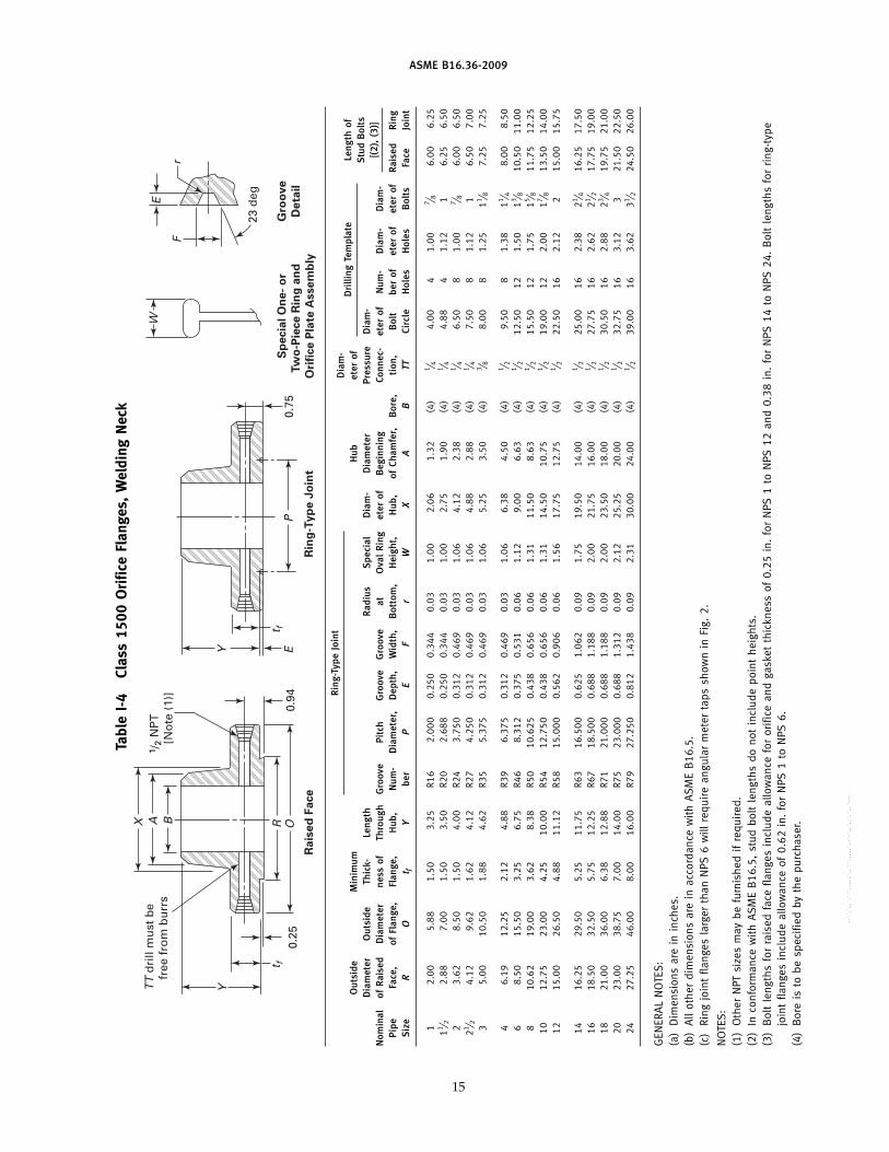
ASME B16.36-2009
Tabl
eI-
4Cl
ass
1500
Ori
fice
Flan
ges,
Wel
ding
Nec
k
0.94
B
TT
dri
ll m
ust
be
fr
ee f
rom
bu
rrs
t f0.
25
Y
A
Ra
ise
d F
ace
Rin
g-T
yp
e J
oin
t
Sp
ecia
l O
ne
- o
r
Tw
o-P
iece
Rin
g a
nd
Ori
fice
Pla
te A
sse
mb
ly
Gro
ov
e
De
tail
X1 /
2 N
PT
[N
ote
(1)
]
OR0.
75
23 d
eg
t fEY
P
F
E
r
W
Rin
g-Ty
peJo
int
Dia
m-
Dri
lling
Tem
plat
eLe
ngth
ofO
utsi
deM
inim
umH
ubet
erof
Stu
dB
olts
Dia
met
erO
utsi
deTh
ick-
Leng
thR
adiu
sS
peci
alD
iam
-D
iam
eter
Pres
sure
Dia
m-
[(2)
,(3
)]N
omin
alof
Rai
sed
Dia
met
erne
ssof
Thro
ugh
Gro
ove
Pitc
hG
roov
eG
roov
eat
Ova
lR
ing
eter
ofB
egin
ning
Conn
ec-
eter
ofN
um-
Dia
m-
Dia
m-
Pipe
Face
,of
Flan
ge,
Flan
ge,
Hub
,N
um-
Dia
met
er,
Dep
th,
Wid
th,
Bot
tom
,H
eigh
t,H
ub,
ofCh
amfe
r,B
ore,
tion
,B
olt
ber
ofet
erof
eter
ofR
aise
dR
ing
Siz
eR
Ot f
Ybe
rP
EF
rW
XA
BTT
Circ
leH
oles
Hol
esB
olts
Face
Join
t
12.
005.
881.
503.
25R1
62.
000
0.25
00.
344
0.03
1.00
2.06
1.32
(4)
1 ⁄ 44.
004
1.00
7 ⁄ 86.
006.
2511 ⁄ 2
2.88
7.00
1.50
3.50
R20
2.68
80.
250
0.34
40.
031.
002.
751.
90(4
)1 ⁄ 4
4.88
41.
121
6.25
6.50
23.
628.
501.
504.
00R2
43.
750
0.31
20.
469
0.03
1.06
4.12
2.38
(4)
1 ⁄ 46.
508
1.00
7 ⁄ 86.
006.
5021 ⁄ 2
4.12
9.62
1.62
4.12
R27
4.25
00.
312
0.46
90.
031.
064.
882.
88(4
)1 ⁄ 4
7.50
81.
121
6.50
7.00
35.
0010
.50
1.88
4.62
R35
5.37
50.
312
0.46
90.
031.
065.
253.
50(4
)3 ⁄ 8
8.00
81.
2511 ⁄ 8
7.25
7.25
46.
1912
.25
2.12
4.88
R39
6.37
50.
312
0.46
90.
031.
066.
384.
50(4
)1 ⁄ 2
9.50
81.
3811 ⁄ 4
8.00
8.50
68.
5015
.50
3.25
6.75
R46
8.31
20.
375
0.53
10.
061.
129.
006.
63(4
)1 ⁄ 2
12.5
012
1.50
13 ⁄ 810
.50
11.0
08
10.6
219
.00
3.62
8.38
R50
10.6
250.
438
0.65
60.
061.
3111
.50
8.63
(4)
1 ⁄ 215
.50
121.
7515 ⁄ 8
11.7
512
.25
1012
.75
23.0
04.
2510
.00
R54
12.7
500.
438
0.65
60.
061.
3114
.50
10.7
5(4
)1 ⁄ 2
19.0
012
2.00
17 ⁄ 813
.50
14.0
012
15.0
026
.50
4.88
11.1
2R5
815
.000
0.56
20.
906
0.06
1.56
17.7
512
.75
(4)
1 ⁄ 222
.50
162.
122
15.0
015
.75
1416
.25
29.5
05.
2511
.75
R63
16.5
000.
625
1.06
20.
091.
7519
.50
14.0
0(4
)1 ⁄ 2
25.0
016
2.38
21 ⁄ 416
.25
17.5
016
18.5
032
.50
5.75
12.2
5R6
718
.500
0.68
81.
188
0.09
2.00
21.7
516
.00
(4)
1 ⁄ 227
.75
162.
6221 ⁄ 2
17.7
519
.00
1821
.00
36.0
06.
3812
.88
R71
21.0
000.
688
1.18
80.
092.
0023
.50
18.0
0(4
)1 ⁄ 2
30.5
016
2.88
23 ⁄ 419
.75
21.0
020
23.0
038
.75
7.00
14.0
0R7
523
.000
0.68
81.
312
0.09
2.12
25.2
520
.00
(4)
1 ⁄ 232
.75
163.
123
21.5
022
.50
2427
.25
46.0
08.
0016
.00
R79
27.2
500.
812
1.43
80.
092.
3130
.00
24.0
0(4
)1 ⁄ 2
39.0
016
3.62
31 ⁄ 224
.50
26.0
0
GEN
ERA
LN
OTE
S:
(a)
Dim
ensi
ons
are
inin
ches
.(b
)A
llot
her
dim
ensi
ons
are
inac
cord
ance
wit
hA
SME
B16
.5.
(c)
Ring
join
tfla
nges
larg
erth
anN
PS6
will
requ
ire
angu
lar
met
erta
pssh
own
inFi
g.2.
NO
TES
:(1
)O
ther
NPT
size
sm
aybe
furn
ishe
dif
requ
ired
.(2
)In
conf
orm
ance
wit
hA
SME
B16
.5,
stud
bolt
leng
ths
dono
tin
clud
epo
int
heig
hts.
(3)
Bol
tle
ngth
sfo
rra
ised
face
flang
esin
clud
eal
low
ance
for
orifi
cean
dga
sket
thic
knes
sof
0.25
in.
for
NPS
1to
NPS
12an
d0.
38in
.fo
rN
PS14
toN
PS24
.B
olt
leng
ths
for
ring
-typ
ejo
int
flang
esin
clud
eal
low
ance
of0.
62in
.fo
rN
PS1
toN
PS6.
(4)
Bor
eis
tobe
spec
ified
byth
epu
rcha
ser.
15
--``,`,,`,```,,,,,`,,```,,,,,`,-`-`,,`,,`,`,,`---
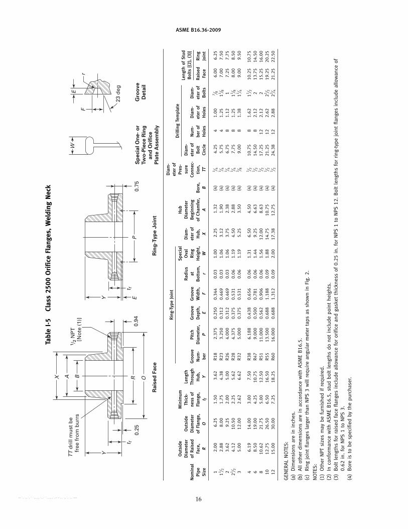
ASME B16.36-2009
Tabl
eI-
5Cl
ass
2500
Ori
fice
Flan
ges,
Wel
ding
Nec
k
0.94
BT
T d
rill
mu
st b
e
free
fro
m b
urr
s
t f
Y
A
Ra
ise
d F
ace
Rin
g-T
yp
e J
oin
t
Sp
ecia
l O
ne
- o
r
Tw
o-P
iece
Rin
g
an
d O
rifi
ce
Pla
te A
sse
mb
ly
Gro
ov
e
De
tail
X
1 /2
NP
T
[No
te (
1)]
OR
23 d
eg
t fEY
P
F
E
r
W
0.25
0.75
Dia
m-
Rin
g-Ty
peJo
int
eter
ofD
rilli
ngTe
mpl
ate
Out
side
Min
imum
Spe
cial
Hub
Pres
-Le
ngth
ofS
tud
Dia
met
erO
utsi
deTh
ick-
Leng
thR
adiu
sO
val
Dia
m-
Dia
met
ersu
reD
iam
-B
olts
[(2)
,(3
)]N
omin
alof
Rai
sed
Dia
met
erne
ssof
Thro
ugh
Gro
ove
Pitc
hG
roov
eG
roov
eat
Rin
get
erof
Beg
inni
ngCo
nnec
-et
erof
Num
-D
iam
-D
iam
-Pi
peFa
ce,
ofFl
ange
,Fl
ange
,H
ub,
Num
-D
iam
eter
,D
epth
,W
idth
,B
otto
m,
Hei
ght,
Hub
,of
Cham
fer,
Bor
e,ti
on,
Bol
tbe
rof
eter
ofet
erof
Rai
sed
Rin
gS
ize
RO
t fY
ber
PE
Fr
WX
AB
TTCi
rcle
Hol
esH
oles
Bol
tsFa
ceJo
int
12.
006.
251.
503.
62R1
82.
375
0.25
00.
344
0.03
1.00
2.25
1.32
(4)
1 ⁄ 44.
254
1.00
7 ⁄ 86.
006.
2511 ⁄ 2
2.88
8.00
1.75
4.38
R23
3.25
00.
312
0.46
90.
031.
063.
121.
90(4
)1 ⁄ 4
5.75
41.
2511 ⁄ 8
7.00
7.50
23.
629.
252.
005.
00R2
64.
000
0.31
20.
469
0.03
1.06
3.75
2.38
(4)
1 ⁄ 46.
758
1.12
17.
257.
7521 ⁄ 2
4.12
10.5
02.
255.
62R2
84.
375
0.37
50.
531
0.06
1.19
4.50
2.88
(4)
1 ⁄ 47.
758
1.25
11 ⁄ 88.
008.
503
5.00
12.0
02.
626.
62R3
25.
000
0.37
50.
531
0.06
1.19
5.25
3.50
(4)
3 ⁄ 89.
008
1.38
11 ⁄ 49.
009.
50
46.
1914
.00
3.00
7.50
R38
6.18
80.
438
0.65
60.
061.
316.
504.
50(4
)1 ⁄ 2
10.7
58
1.62
11 ⁄ 210
.25
10.7
56
8.50
19.0
04.
2510
.75
R47
9.00
00.
500
0.78
10.
061.
449.
256.
63(4
)1 ⁄ 2
14.5
08
2.12
213
.75
14.5
08
10.6
221
.75
5.00
12.5
0R5
111
.000
0.56
20.
906
0.06
1.56
12.0
08.
63(4
)1 ⁄ 2
17.2
512
2.12
215
.25
16.0
010
12.7
526
.50
6.50
16.5
0R5
513
.500
0.68
81.
188
0.09
1.88
14.7
510
.75
(4)
1 ⁄ 221
.25
122.
6221 ⁄ 2
19.2
520
.25
1215
.00
30.0
07.
2518
.25
R60
16.0
000.
688
1.31
20.
092.
0017
.38
12.7
5(4
)1 ⁄ 2
24.3
812
2.88
23 ⁄ 421
.25
22.5
0
GEN
ERA
LN
OTE
S:
(a)
Dim
ensi
ons
are
inin
ches
.(b
)A
llot
her
dim
ensi
ons
are
inac
cord
ance
wit
hA
SME
B16
.5.
(c)
Ring
join
tfla
nges
larg
erth
anN
PS3
will
requ
ire
angu
lar
met
erta
psas
show
nin
Fig.
2.
NO
TES
:(1
)O
ther
NPT
size
sm
aybe
furn
ishe
dif
requ
ired
.(2
)In
conf
orm
ance
wit
hA
SME
B16
.5,
stud
bolt
leng
ths
dono
tin
clud
epo
int
heig
hts.
(3)
Bol
tle
ngth
sfo
rra
ised
face
flang
esin
clud
eal
low
ance
for
orifi
cean
dga
sket
thic
knes
sof
0.25
in.
for
NPS
1to
NPS
12.
Bol
tle
ngth
sfo
rri
ng-t
ype
join
tfla
nges
incl
ude
allo
wan
ceof
0.62
in.
for
NPS
1to
NPS
3.(4
)B
ore
isto
besp
ecifi
edby
the
purc
hase
r.
16--``,`,,`,```,,,,,`,,```,,,,,`,-`-`,,`,,`,`,,`---

ASME B16.36-2009
MANDATORY APPENDIX IIDIMENSIONAL DATA FOR CLASS 400 FLANGES IN
U.S. CUSTOMARY UNITS
This Appendix is an int egra l par t ofASME B16.36-2009, and it is placed after the main textfor convenience. Table II-1, included in this Appendix,provides dimensional data in U.S. Customary units forClass 400 flanges.
17
--``,`,,`,```,,,,,`,,```,,,,,`,-`-`,,`,,`,`,,`---

ASME B16.36-2009
Tabl
eII-
1Cl
ass
400
Ori
fice
Flan
ges,
Wel
ding
Nec
k
0.94
B
TT
dri
ll m
ust
be
fr
ee f
rom
bu
rrs
t f
Y
A
Ra
ise
d F
ace
Rin
g-T
yp
e J
oin
t
Sp
ecia
l O
ne
- o
r
Tw
o-P
iece
Rin
g a
nd
Ori
fice
Pla
te A
sse
mb
ly
Gro
ov
e
De
tail
X1 /
2 N
PT
[N
ote
(1)
]
OR0.
75
23 d
eg
t fEY
P
F
E
r
W
0.25
Rin
g-Ty
peJo
int
Dia
m-
Dri
lling
Tem
plat
eLe
ngth
ofO
utsi
deM
inim
umH
ubet
erof
Stu
dB
olts
Dia
met
erO
utsi
deTh
ick-
Leng
thR
adiu
sS
peci
alD
iam
-D
iam
eter
Pres
sure
Dia
m-
[(2)
,(3
)]N
omin
alof
Rai
sed
Dia
met
erne
ssof
Thro
ugh
Gro
ove
Pitc
hG
roov
eG
roov
eat
Ova
lR
ing
eter
ofB
egin
ning
Conn
ec-
eter
ofN
um-
Dia
m-
Dia
m-
Pipe
Face
,of
Flan
ge,
Flan
ge,
Hub
,N
um-
Dia
met
er,
Dep
th,
Wid
th,
Bot
tom
,H
eigh
t,H
ub,
ofCh
amfe
r,B
ore,
tion
,B
olt
ber
ofet
erof
eter
ofR
aise
dR
ing
Siz
eR
Ot f
Ybe
rP
EF
rW
XA
BTT
Circ
leH
oles
Hol
esB
olts
Face
Join
t
1 11 ⁄ 2 2Fo
rN
PS3
and
smal
ler,
use
Clas
s60
0.21 ⁄ 2 3 4
6.19
10.0
01.
503.
50R3
75.
875
0.31
20.
469
0.03
1.06
5.75
4.50
(4)
1 ⁄ 27.
888
1.00
7 ⁄ 85.
506.
006
8.50
12.5
01.
624.
06R4
58.
312
0.31
20.
469
0.03
1.06
8.12
6.63
(4)
1 ⁄ 210
.62
121.
007 ⁄ 8
6.25
6.50
810
.62
15.0
01.
884.
62R4
910
.625
0.31
20.
469
0.03
1.06
10.2
58.
63(4
)1 ⁄ 2
13.0
012
1.12
16.
757.
2510
12.7
517
.50
2.12
4.88
R53
12.7
500.
312
0.46
90.
031.
0612
.62
10.7
5(4
)1 ⁄ 2
15.2
516
1.25
11 ⁄ 87.
508.
0012
15.0
020
.50
2.25
5.38
R57
15.0
000.
312
0.46
90.
031.
0614
.75
12.7
5(4
)1 ⁄ 2
17.7
516
1.38
11 ⁄ 48.
008.
50
1416
.25
23.0
02.
395.
88R6
116
.500
0.31
20.
469
0.03
1.06
16.7
514
.00
(4)
1 ⁄ 220
.25
201.
3811 ⁄ 4
8.25
9.00
1618
.50
25.5
02.
506.
00R6
518
.500
0.31
20.
469
0.03
1.19
19.0
016
.00
(4)
1 ⁄ 222
.50
201.
5013 ⁄ 8
8.75
9.25
1821
.00
28.0
02.
626.
50R6
921
.000
0.31
20.
469
0.03
1.19
21.0
018
.00
(4)
1 ⁄ 224
.75
241.
5013 ⁄ 8
9.25
9.50
2023
.00
30.5
02.
756.
62R7
323
.000
0.37
50.
531
0.06
1.25
23.1
220
.00
(4)
1 ⁄ 227
.00
241.
6211 ⁄ 2
9.75
10.2
524
27.2
536
.00
3.00
6.88
R77
27.2
500.
438
0.65
60.
061.
4427
.62
24.0
0(4
)1 ⁄ 2
32.0
024
1.88
13 ⁄ 411
.00
11.5
0
GEN
ERA
LN
OTE
S:
(a)
Dim
ensi
ons
are
inin
ches
.(b
)A
llot
her
dim
ensi
ons
are
inac
cord
ance
wit
hA
SME
B16
.5.
(c)
Ring
join
tfla
nge
inN
PS24
will
requ
ire
anan
gula
rm
eter
tap
assh
own
inFi
g.2.
NO
TES
:(1
)O
ther
NPT
size
sm
aybe
furn
ishe
dif
requ
ired
.(2
)In
conf
orm
ance
wit
hA
SME
B16
.5,
stud
bolt
leng
ths
dono
tin
clud
epo
int
heig
hts.
(3)
Bol
tle
ngth
sfo
rra
ised
face
flang
esin
clud
eal
low
ance
for
orifi
cean
dga
sket
thic
knes
sof
0.25
in.
for
NPS
4to
NPS
12an
d0.
38in
.fo
rN
PS14
toN
PS24
.B
olt
leng
ths
for
ring
-typ
ejo
int
flang
esin
clud
eal
low
ance
of0.
62in
.fo
rN
PS4
toN
PS10
,0.
75in
.fo
rN
PS12
toN
PS18
,an
d0.
88in
.fo
rN
PS20
.(4
)B
ore
isto
besp
ecifi
edby
the
purc
hase
r.
18
--``,`,,`,```,,,,,`,,```,,,,,`,-`-`,,`,,`,`,,`---

ASME B16.36-2009
MANDATORY APPENDIX IIIREFERENCES
The following is a list of publications referenced inthis Standard. The latest editions of ASME publicationsare to be used.ASME B1.20.1, Pipe Threaded, General Purpose (Inch)ASME B16.5, Pipe Flanges and Flanged FittingsASME B16.11, Forged Fittings, Socket-Welding and
ThreadedASME B16.21, Nonmetallic Gaskets for Pipe FlangesASME Boiler and Pressure Vessel Code: Section I, Power
Boilers; Section II, Materials; Section III, NuclearPower Plant Components; Section VIII, Divisions 1and 2, Pressure Vessels
Publisher: The American Society of MechanicalEngineers (ASME), Three Park Avenue, New York,
19
NY 10016-5990; Order Department: 22 Law Drive, P.O.Box 2300, Fairfield, NJ 07007-2300 (www.asme.org)
ISO 9000:2005, Quality management systems —Fundamentals and vocabulary
ISO 9001:2008, Quality management systems —Requirements
ISO 9004:2000, Quality management systems —Guidelines for performance improvements
Publisher: International Organization forStandardization (ISO), 1 ch. de la Voie-Creuse, Casepostale 56, CH-1211 Geneve 20, Switzerland/Suisse(www.iso.org)
--``,`,,`,```,,,,,`,,```,,,,,`,-`-`,,`,,`,`,,`---

ASME B16.36-2009
NONMANDATORY APPENDIX AQUALITY SYSTEM PROGRAM
The products manufactured in accordance with thisStandard shall be produced under a quality system pro-gram following the principles of an appropriate stan-dard from the ISO 9000 series.1 A determination of theneed for registration, certification, or both, of the product
1 The series is also available from the American NationalStandards Institute (ANSI) and the American Society for Quality(ASQ) as American National Standards that are identified by aprefix “Q” replacing the prefix “ISO.” Each standard of the seriesis listed under Mandatory Appendix III.
20
manufacturer’s quality system program by an indepen-dent organization shall be the responsibility of the manu-facturer. The detailed documentation demonstratingprogram compliance shall be available to the purchaserat the manufacturer ’s facility. A written summarydescription of the program utilized by the product man-ufacturer shall be available to the purchaser uponrequest. The product manufacturer is defined as theentity whose name or trademark appears on the productin accordance with the marking or identification require-ments of this Standard.
--``,`,,`,```,,,,,`,,```,,,,,`,-`-`,,`,,`,`,,`---

B16 AMERICAN NATIONAL STANDARDS FOR PIPING,PIPE FLANGES, FITTINGS, AND VALVES
Gray Iron Pipe Flanges and Flanged Fittings (Classes 25, 125, and 250) . . . . . . . . . . . . . . . . . . . . . . . . . . . . . . . . . . . . . . . . . . . . . . . B16.1-2005Malleable Iron Threaded Fittings: Classes 150 and 300. . . . . . . . . . . . . . . . . . . . . . . . . . . . . . . . . . . . . . . . . . . . . . . . . . . . . . . . . . . . . B16.3-2006Gray Iron Threaded Fittings: Classes 125 and 250 . . . . . . . . . . . . . . . . . . . . . . . . . . . . . . . . . . . . . . . . . . . . . . . . . . . . . . . . . . . . . . . . . B16.4-2006Pipe Flanges and Flanged Fittings NPS 1⁄2 Through NPS 24 Metric/Inch Standard . . . . . . . . . . . . . . . . . . . . . . . . . . . . . . . . . . . . . . . . B16.5-2009Factory-Made Wrought Buttwelding Fittings. . . . . . . . . . . . . . . . . . . . . . . . . . . . . . . . . . . . . . . . . . . . . . . . . . . . . . . . . . . . . . . . . . . . . . . B16.9-2007Face-to-Face and End-to-End Dimensions of Valves . . . . . . . . . . . . . . . . . . . . . . . . . . . . . . . . . . . . . . . . . . . . . . . . . . . . . . . .B16.10-2000 (R2009)Forged Fittings, Socket-Welding and Threaded . . . . . . . . . . . . . . . . . . . . . . . . . . . . . . . . . . . . . . . . . . . . . . . . . . . . . . . . . . . . . . . . . . . B16.11-2009Cast Iron Threaded Drainage Fittings . . . . . . . . . . . . . . . . . . . . . . . . . . . . . . . . . . . . . . . . . . . . . . . . . . . . . . . . . . . . . . . . . . . .B16.12-2009 (R2014)Ferrous Pipe Plugs, Bushings, and Locknuts with Pipe Threads . . . . . . . . . . . . . . . . . . . . . . . . . . . . . . . . . . . . . . . . . . . . . . . . . . . . . B16.14-1991Cast Copper Alloy Threaded Fittings. . . . . . . . . . . . . . . . . . . . . . . . . . . . . . . . . . . . . . . . . . . . . . . . . . . . . . . . . . . . . . . . . . . . . . . . . . . . B16.15-2006Cast Copper Alloy Solder Joint Pressure Fittings . . . . . . . . . . . . . . . . . . . . . . . . . . . . . . . . . . . . . . . . . . . . . . . . . . . . . . . . . . .B16.18-2001 (R2005)Metallic Gaskets for Pipe Flanges: Ring-Joint, Spiral-Wound, and Jacketed . . . . . . . . . . . . . . . . . . . . . . . . . . . . . . . . . . . . . . . . . . . . . B16.20-2007Nonmetallic Flat Gaskets for Pipe Flanges . . . . . . . . . . . . . . . . . . . . . . . . . . . . . . . . . . . . . . . . . . . . . . . . . . . . . . . . . . . . . . . . . . . . . . . B16.21-2005Wrought Copper and Copper Alloy Solder Joint Pressure Fittings. . . . . . . . . . . . . . . . . . . . . . . . . . . . . . . . . . . . . . . . . . . . . .B16.22-2001 (R2005)Cast Copper Alloy Solder Joint Drainage Fittings: DWV . . . . . . . . . . . . . . . . . . . . . . . . . . . . . . . . . . . . . . . . . . . . . . . . . . . . . .B16.23-2002 (R2006)Cast Copper Alloy Pipe Flanges and Flanged Fittings: Classes 150, 300, 600, 900, 1500, and 2500 . . . . . . . . . . . . . . . . . . . . . . . B16.24-2006Buttwelding Ends. . . . . . . . . . . . . . . . . . . . . . . . . . . . . . . . . . . . . . . . . . . . . . . . . . . . . . . . . . . . . . . . . . . . . . . . . . . . . . . . . . . . . . . . . . . B16.25-2007Cast Copper Alloy Fittings for Flared Copper Tubes. . . . . . . . . . . . . . . . . . . . . . . . . . . . . . . . . . . . . . . . . . . . . . . . . . . . . . . . . . . . . . . . B16.26-2006Wrought Steel Buttwelding Short Radius Elbows and Returns . . . . . . . . . . . . . . . . . . . . . . . . . . . . . . . . . . . . . . . . . . . . . . . . . . . . . . . B16.28-1994Wrought Copper and Wrought Copper Alloy Solder Joint Drainage Fittings — DWV. . . . . . . . . . . . . . . . . . . . . . . . . . . . . . . . . . . . . . . B16.29-2007Manually Operated Metallic Gas Valves for Use in Gas Piping Systems up to 125 psi
(Sizes NPS 1⁄2 Through NPS 2) . . . . . . . . . . . . . . . . . . . . . . . . . . . . . . . . . . . . . . . . . . . . . . . . . . . . . . . . . . . . . . . . . . . . . . .B16.33-2002 (R2007)Valves — Flanged, Threaded, and Welding End. . . . . . . . . . . . . . . . . . . . . . . . . . . . . . . . . . . . . . . . . . . . . . . . . . . . . . . . . . . . . . . . . . . B16.34-2004Orifice Flanges . . . . . . . . . . . . . . . . . . . . . . . . . . . . . . . . . . . . . . . . . . . . . . . . . . . . . . . . . . . . . . . . . . . . . . . . . . . . . . . . . . . . . . . . . . . . . B16.36-2009Large Metallic Valves for Gas Distribution Manually Operated, NPS 21⁄2 (DN 65)
to NPS 12 (DN 300), 125 psig (8.6 bar) Maximum. . . . . . . . . . . . . . . . . . . . . . . . . . . . . . . . . . . . . . . . . . . . . . . . . . . . . . . . . . . . . . B16.38-2007Malleable Iron Threaded Pipe Unions: Classes 150, 250, and 300. . . . . . . . . . . . . . . . . . . . . . . . . . . . . . . . . . . . . . . . . . . . . . . . . . . B16.39-2009Manually Operated Thermoplastic Gas Shutoffs and Valves in Gas Distribution Systems . . . . . . . . . . . . . . . . . . . . . . . . . . . . . . . . . B16.40-2008Functional Qualification Requirements for Power Operated Active Valve Assemblies for Nuclear Power Plants . . . . . . . . .B16.41-1983 (R1989)Ductile Iron Pipe Flanges and Flanged Fittings: Classes 150 and 300 . . . . . . . . . . . . . . . . . . . . . . . . . . . . . . . . . . . . . . . . .B16.42-1998 (R2006)Manually Operated Metallic Gas Valves for Use in Aboveground Piping Systems Up To 5 PSI . . . . . . . . . . . . . . . . . . . . . .B16.44-2002 (R2007)Cast Iron Fittings for Sovent® Drainage Systems. . . . . . . . . . . . . . . . . . . . . . . . . . . . . . . . . . . . . . . . . . . . . . . . . . . . . . . . . . .B16.45-1998 (R2006)Large Diameter Steel Flanges NPS 26 Through NPS 60 Metric/Inch Standard . . . . . . . . . . . . . . . . . . . . . . . . . . . . . . . . . . . . . . . . . . B16.47-2006Steel Line Blanks. . . . . . . . . . . . . . . . . . . . . . . . . . . . . . . . . . . . . . . . . . . . . . . . . . . . . . . . . . . . . . . . . . . . . . . . . . . . . . . . . . . . . . . . . . . B16.48-2005Factory-Made Wrought Steel Buttwelding Induction Bends for Transportation and Distribution Systems . . . . . . . . . . . . . . . . . . . . . B16.49-2007Wrought Copper and Copper Alloy Braze-Joint Pressure Fittings . . . . . . . . . . . . . . . . . . . . . . . . . . . . . . . . . . . . . . . . . . . . . .B16.50-2001 (R2008)
The ASME Publications Catalog shows a complete list of all the Standards published by the Society. For a complimentary catalog, or the latestinformation about our publications, call 1-800-THE-ASME (1-800-843-2763).
--``,`,,`,```,,,,,`,,```,,,,,`,-`-`,,`,,`,`,,`---

ASME Services
ASME is committed to developing and delivering technical information. At ASME’s Information Central, we make every effort to answer yourquestions and expedite your orders. Our representatives are ready to assist you in the following areas:
ASME Press Member Services & Benefits Public InformationCodes & Standards Other ASME Programs Self-Study CoursesCredit Card Orders Payment Inquiries Shipping InformationIMechE Publications Professional Development Subscriptions/Journals/MagazinesMeetings & Conferences Short Courses Symposia VolumesMember Dues Status Publications Technical Papers
How can you reach us? It’s easier than ever!
There are four options for making inquiries* or placing orders. Simply mail, phone, fax, or E-mail us and an InformationCentral representative will handle your request.
Mail Call Toll Free Fax—24 hours E-Mail—24 hoursASME US & Canada: 800-THE-ASME 973-882-1717 [email protected] Law Drive, Box 2900 (800-843-2763) 973-882-5155Fairfield, New Jersey Mexico: 95-800-THE-ASME07007-2900 (95-800-843-2763)
Universal: 973-882-1167
* Information Central staff are not permitted to answer inquiries about the technical content of this code or standard. Information as towhether or not technical inquiries are issued to this code or standard is shown on the copyright page. All technical inquiries must besubmitted in writing to the staff secretary. Additional procedures for inquiries may be listed within.
--``,`,,`,```,,,,,`,,```,,,,,`,-`-`,,`,,`,`,,`---

J04609
ASME B16.36-2009
--``,`,,`,```,,,,,`,,```,,,,,`,-`-`,,`,,`,`,,`---