organization of a radioisotope based molecular biology ... heteroduplex tracking assay (hta), dna...
TRANSCRIPT

IAEA-TECDOC-1528
Organization of aRadioisotope Based Molecular
Biology Laboratory
December 2006

IAEA-TECDOC-1528
Organization of aRadioisotope Based Molecular
Biology Laboratory
December 2006

The originating Section of this publication in the IAEA was:
Nuclear Medical Section International Atomic Energy Agency
Wagramer Strasse 5 P.O. Box 100
A-1400 Vienna, Austria
ORGANIZATION OF A RADIOISOTOPE BASED MOLECULAR BIOLOGY LABORATORY
IAEA, VIENNA, 2006 IAEA-TECDOC-1528 ISBN 92–0–114406–7
ISSN 1011–4289 © IAEA, 2006
Printed by the IAEA in Austria December 2006

FOREWORD
Polymerase chain reaction (PCR) has revolutionized the application of molecular techniques to medicine. Together with other molecular biology techniques it is being increasingly applied to human health for identifying prognostic markers and drug resistant profiles, developing diagnostic tests and genotyping systems and for treatment follow-up of certain diseases in developed countries. Developing Member States have expressed their need to also benefit from the dissemination of molecular advances. The use of radioisotopes, as a step in the detection process or for increased sensitivity and specificity is well established, making it ideally suitable for technology transfer. Many molecular based projects using isotopes for detecting and studying micro organisms, hereditary and neoplastic diseases are received for approval every year. In keeping with the IAEA’s programme, several training activities and seminars have been organized to enhance the capabilities of developing Member States to employ in vitro nuclear medicine technologies for managing their important health problems and for undertaking related basic and clinical research. The background material for this publication was collected at training activities and from feedback received from participants at research and coordination meetings. In addition, a consultants’ meeting was held in June 2004 to compile the first draft of this report. Previous IAEA TECDOCS, namely IAEA-TECDOC-748 and IAEA-TECDOC-1001, focused on molecular techniques and their application to medicine while the present publication provides information on organization of the laboratory, quality assurance and radio-safety. The technology has specific requirements of the way the laboratory is organized (e.g. for avoiding contamination and false positives in PCR) and of quality assurance in order to provide accurate information to decision makers. In addition while users of the technology accept the scientific rationale of using radio-isotopes: they often have concerns related to safety. Member States have repeatedly requested help for training when first establishing radioactive-based molecular biology laboratories in particular in radiosafety and quality assurance. The current TECDOC has been prepared in response to these requests and requirements. It represents one of the IAEA’s many efforts to contribute with the worldwide implementation of these techniques, and to be a relevant source of information to be used by molecular scientists, major national research institutions, laboratory workers and national health institutions authorities. The IAEA wishes to thank all authors and in particular to acknowledge the contribution of the following in the preparation of this publication: L. Ranford-Cartwright, T. Victor, O. Fernandes and L. García Aguirre. The IAEA officer responsible for this publication was B. Khan of the Division of Human Health.

EDITORIAL NOTE
The use of particular designations of countries or territories does not imply any judgement by the publisher, the IAEA, as to the legal status of such countries or territories, of their authorities and institutions or of the delimitation of their boundaries.
The mention of names of specific companies or products (whether or not indicated as registered) does not imply any intention to infringe proprietary rights, nor should it be construed as an endorsement or recommendation on the part of the IAEA.
CONTENTS
1. INTRODUCTION…………………………………………………………......................... 1
2. RADIOISOTOPE-BASED MOLECULAR BIOLOGY……………................................... 2 2.1. Sensitivity …………………………………………………………............................ 2 2.2. Specificity ………………………………………………………… ........................... 2 2.3. Cost-effectiveness ………………………………………………… ........................... 2 2.4. Safety issues ………………………………………………………............................ 3
3. RADIOISOTOPE-BASED METHODS…..………………………….…… ........................ 4 3.1. Polymerase chain reaction ........................................................................................... 4 3.2. Dot-blot assay .............................................................................................................. 5 3.3. Restriction fragment length polymorphism analysis……..…… ................................. 6 3.4. Single stranded conformational polymorphism ........................................................... 7 3.5. Amplified fragment length polymorphism .................................................................. 7 3.6. Mismatch cleavage assay ............................................................................................. 8 3.7. Heteroduplex tracking assay ........................................................................................ 8 3.8. DNA sequencing ……………….………………………………...... .......................... 8 3.9. Microsatellite detection ……………………………………………........................... 9 3.10. DNA “footprinting” for analysis of protein-nucleic acid interactions ............. 9 3.11. Protein truncation test..................................................................................... 10 3.12. Reporter gene assays ...................................................................................... 11 3.13. Scintillation proximity assay.......................................................................... 11 3.14. Telomerase assay ........................................................................................... 11 3.15. Macroarray and microarray chip technology ................................................. 12 3.16. Stable-isotope-assisted maldi-tof mass spectrometry .................................... 13 3.17. Stable isotope coded affinity tags................................................................... 13 3.18. Solution NMR with stable isotopes................................................................ 13
4. DESIGNING A MOLECULAR BIOLOGY LABORATORY .......................................... 15
5. GENERAL WORKFLOW.................................................................................................. 16
6. DESCRIPTION OF THE AREAS ...................................................................................... 17 6.1. Area 1: Clean area …………………………………………………......................... 17 6.2. Area 2: Extraction nucleic acids from clinical specimens ......................................... 18 6.3. Area 3: Template preparation and PCR ..................................................................... 19 6.4. Area 4a: Post-amplification area — non radioactive ................................................ 19 6.5. Area 4b: The radiation area ....................................................................................... 20
7. PREVENTION OF PCR CONTAMINATION AND GOOD LABORATORY PRACTICES............................................................................. 23
8. QUALITY CONTROL ....................................................................................................... 26
9. BASIC PRINCIPLES FOR HANDLING RADIOACTIVE MATERIALS IN THE LABORATORY.............................................. 27 9.1. Information about ionizing radiation and radioactivity ............................................. 27
9.1.1. Types of radioactive decay............................................................................. 27

9.1.2. Interaction of radioactivity with matter .......................................................... 28 9.1.3. Principles of shielding……………………………………… ........................ 29 9.1.4. Effects of radioactivity on humans................................................................. 30
9.2. Detection and measurement of radioactivity ............................................................ 31 9.2.1. Survey instruments ......................................................................................... 31 9.2.2. Personal monitoring devices........................................................................... 31
9.3. Establishment and management of a radioactive facility........................................... 32 9.3.1. The regulatory framework for working with
ionizing and radiation dose limits .................................................................. 33 9.3.2. General principles and procedures ................................................................. 33 9.3.3. Dose limits...................................................................................................... 33 9.3.4. Government regulations on radioactive substances ....................................... 33
9.4. Basic principles for handling radioactive material in the laboratory ........................ 35 9.4.1. Design of radiation containment facility ......................................................... 37 9.4.2. Receiving radioactive material ........................................................................ 38 9.4.3. Preparing for a radioactive experiment ........................................................... 39 9.4.4. Procedure when finished working on the radioactive bench ........................... 41 9.4.5. Guidelines for prevention of radioactive contamination.................................. 43 9.4.6. Decontamination ............................................................................................. 44 9.4.7. Collection and storage of radioactive waste .................................................... 46
10. EXAMPLES OF PROTOCOLS USED AT RADIOISOTOPE-BASED MOLECULAR BIOLOGY LABORATORY ................................................................... 50 10.1. Oligonucleotide labelling using (γ-32P) ATP ...................................................... 50 10.2. 32P-α-dATP-labelling of PCR products ............................................................... 51
11. FURTHER INFORMATION ............................................................................................ 58
APPENDICES.......................................................................................................................... 59 Appendix I: Terms used to describe radioactivity ........................................................... 61 Appendix II: Characteristics of radionuclides commonly
used in molecular biology............................................................................ 62 Appendix III: Sample Forms ............................................................................................. 63
III.1. Radioactive material permit .................................................................. 63 III.2. Ionizing radiation authorization permit................................................. 65 III.3. Room use log form................................................................................ 66 III.4. Accident report form ............................................................................ 67 III.5. Radioactivity stock record form............................................................ 68
Appendix IV: Labelling..................................................................................................... 69 IV.1. Door label for controlled area ............................................................... 69 IV.2. Label for door of supervised radiation area .......................................... 70 IV.3. Label for freezer or refrigerator cont. radioactive material .................. 71 IV.4. Miscellaneous labels ............................................................................. 72
Appendix V: Sample scheme of work .............................................................................. 73
REFERENCES......................................................................................................................... 77
IAEA PUBLICATIONS ON MOLECULAR DIAGNOSIS, NUCLEAR MEDICINE AND RADIO SAFETY ................................................................... 83
CONTRIBUTORS TO DRAFTING AND REVIEW ............................................................. 85

1. INTRODUCTION Molecular biology has revolutioned science and medicine as it presents the capability of revealing how several intracellular phenomena occur and explaining the human host infecting microorganism (virus, bacteria, fungi, protozoa, helminthes) relationship. This feature encompasses diverse applications such as taxonomy, evolution, diagnosis, characterization, drug-resistance, etc. Before the discovery of Polymerase Chain Reaction (PCR) by Kary Mullis in 1983, obtaining a specific sequence of DNA in quantities sufficient for study was difficult, time-consuming, and expensive. PCR applications in clinical diagnosis and research developed very fast, altering the design and set up of a molecular biology laboratory. They can be used to detect very small amounts of target genome from microorganisms or patient. These methods need to follow certain established procedures since the amplification of a target gene could lead to the contamination of other samples, pipettes, or the working area. Due to these limitations, special care must be taken in the design and organization of a molecular biology laboratory. Ever since the inception of molecular biology techniques, radionuclide based methods have been an integral component of their development and represent one of the tools for their application in diagnosis and research. Radionuclide based molecular techniques have proved to be highly sensitive, specific, robust and cost effective in various application contexts. They are also amenable to quantitative measurement. Various molecular biology techniques e.g. dot blot assay, restriction fragment length polymorphism (RFLP), single stranded conformational polymorphism (SSCP), amplified fragment length polymorphism (AFLP), mismatch cleavage assay, heteroduplex tracking assay (HTA), DNA sequencing, microsatellite detection, scintillation proximity assay (SPA), macroarray chip technology, isotope coded affinity tags (ICAT), etc. may use isotopes. The development of an adequate infrastructure and human resource plays a vital role in the success of technology. Due to the generic nature and universal applicability of the technology, a laboratory that is set up for radionuclide based molecular methods, can easily be adapted for all other molecular techniques using non-radioisotopic methods or even commercial kits. Safe handling and proper disposal of radioisotopes are the key issues of concern when using them in molecular biology. However, both these issues can be easily and conveniently accomplished by appropriate training, use of protective devices and following guidelines for use of radioisotopes and for waste management. Further, safety is less of a concern with low energy isotopes which are usually used in molecular biology techniques since these emit considerably weaker particles. Also safety is not a limitation for the use of stable isotopes, which are finding new applications in molecular biology.
1

2. RADIOISOTOPE-BASED MOLECULAR BIOLOGY Many radioisotope-based methods can be described as important tools for human and animal diseases research and diagnosis. Despite the emergence of alternatives, radioisotopes still have dedicated users for the established applications, and continue to provide emerging applications. 2.1. Sensitivity Due to the exquisite sensitivity, that allows detection of as little as 0.1 pg of target DNA [1], probes labelled with isotopes (e.g. 32P) maintain an important place in DNA hybridization [2], a widely used molecular biology technique. Isotope-labelled products can provide up to approximately 125-fold increase in sensitivity over ethidium bromide staining, with a maximum of 625-fold greater sensitivity with a 3-day exposure [3]. The sensitivity of radioisotope labelled probes has been demonstrated to be 10-fold [4] to 50-fold higher than biotin labelled probes [5]; and 100-fold higher than alkaline-phosphatase labelled probes [4]. This difference provides a crucial advantage when very small copy numbers of integrated DNA have to be detected e.g. by techniques like in-situ hybridization [6]. The sensitivity of isotopic techniques also provides an advantage where a small minority of strains has to be detected e.g. a small percentage of resistant mutants in a large population of susceptible wild type strains [7]. Also, for viral load quantitation, liquid hybridization with radiolabelled probes was found to be more accurate than a non-radioactive (chemiluminiscent) hybrid capture assay [8,9]. For genomic sequencing, despite the use of lasers and CCD cameras, the sensitivity of detection of fluorescent DNA fragments by automated sequencers is less than is achievable with isotopic labelling [10]. 2.2. Specificity Isotopic labels provide a good “signal to noise” ratio and higher specificity than fluorescent or enzymatic labels. The strong and unique signal emitted by radiolabels stands out against the background, whereas the signal from a fluorescent probe is a visible spectrum photon, which may arise by non-specific interferants [11]. Further, when radioisotopes are incorporated in techniques like mobility assays, they improve the readability and interpretation of results [12]. In manual sequencing, 35S gives discrete and sharp bands on autoradiograph, due to its low energy β emission and limited scatter. The inherent fluorescence in many biological samples frequently leads to high backgrounds in hybridization experiments [2]. The problem of poor signal-to-background ratio also occurs in the system that uses biotinylated probes with streptavidin, due to the presence of biotin in tissues [13]. Other techniques like silver staining, used for single strand conformational polymorphism (SSCP), also have a problem with background staining [14]. 2.3. Cost effectiveness Cost estimates show that radioisotopic hybridization is less expensive than non-radioisotopic probe-based methods. The cost of mobility assays, SSCP and dot-blot hybridization with radiolabelled probes is estimated at $5 to $10 [14]. The equipment required includes a thermocycler and electrophoresis apparatus, and costs less than $10 000. Also, nylon membranes can be repeatedly reused for hybridization. The probe can be stripped off the
2

membrane after autoradiography, and re-probing carried out with other sets of radiolabelled probes. Automated sequencing hardware based on the detection of fluorescence has a much higher initial outlay of funds [9]. For automated sequencing, a fluorescence-based sequencer may cost $100 000 to $120 000 [15]. Therefore, though automated DNA sequencing following polymerase chain reaction (PCR) amplification of the gene target is a widely used technique in developed countries, it is not readily available in routine laboratories and developing countries [16]. However, manual sequencing using the radioisotope 35S is significantly less expensive to establish, as it only requires equipment costing $2000 to $3000 (for a vertical sequencing gel electrophoresis system and accessories). Microarrays can be used to detect thousands of genes using a single glass “chip” with immobilized probes, and fluorescence-based detection. However, this technology remains out of the reach of academic laboratories, due to the prohibitive cost of equipment (about $200 000). In such settings, a relatively cost-effective method using nylon macroarray chips and radioisotopic (autoradiography) detection is a viable alternative. This is amenable to small-scale automation, with probes to a couple of hundred genes immobilized on each nylon chip [17]. 2.4. Safety issues Safety is a concern with the use and disposal of radioisotopes. However, laboratory certification, protective equipment, clear guidelines for use and disposal, appropriate training, and well-established international and national regulatory authorities help to circumvent such problems with radioisotopes. Safety is less of a concern with low-energy radioisotopes, and 35S and 33P emit considerably weaker beta particles at 0.167 and 0.248 MeV [2]. However, safety is not a limitation for the use of stable isotopes, which are finding new applications in molecular biology. It is extremely important to realize that non-radioisotopic methods are not without their share of safety problems. Certain fluorescent and chemiluminiscent substrates, and their products, are contact allergens, and even potential carcinogens [18, 19]. The safe disposal of these chemicals and additional costs involved are oft-neglected issues.
3

3. RADIOISOTOPIC-BASED METHODS Various molecular biology methods that use isotopes are described in this section1. They are based on PCR amplification in order to work with a measurable amount of DNA. 3.1. Polymerase chain reaction The advent of the polymerase chain reaction (PCR) meant that insufficiencies in quantity of DNA were no longer a limitation in molecular biology research and diagnostic procedures. It is a method that efficiently increases the number of DNA molecules in a logarithmic and controlled fashion. The DNA sequence (template) to be amplified is incubated in the same tube with a DNA polymerase, dideoxy nucleoside triphosphates (dNTPs) and a pair of small sequences of around 20 nucleotides (primers), which are complementary to the DNA template. The DNA polymerase reads the DNA template in the 3’-5’ direction and synthesizes a new complementary strand in 5’-3’ direction, using the provided free dideoxy nucleoside triphosphates (dATP, dCTP, dGTP and dTTP) as building blocks (Fig. 1). To complete this process the polymerase must reach the DNA template, meaning that the DNA molecule must be denaturated by heating to 95ºC. At this high temperature, the majority of enzymes are denatured. The polymerase is heat-stable as it is derived from a bacteria that lives in hot springs at high temperatures, Thermophilus aquaticus, where the name Taq polymerase comes from. This characteristic permits the amplification cycle to occur in three steps see Fig. 2: the first step denaturates the DNA molecule using heat (95ºC) and separates its two strands; the second step allows the primers to anneal and hybridize with each strand of the DNA at the lower temperature (37–60ºC) and the third step takes place by increasing the temperature (72ºC).
FIG. 1. Representation of the three steps of a PCR cycle and the process involved in
duplicating the number of DNA template.
1. Text published in DAR, L., KHAN, B. The role and future of in vitro isotopic techniques in molecular biology. World J. Nucl. Med 3 (2004) 1:72–1.
4

FIG. 2. A PCR assay consists in the repetition of cycles. The diagram of one cycle is illustrated in the
figure, consisting of three consecutive steps: denaturation, annealing and elongation, respectively.
Why do we need primers? We need primers because the Taq polymerase is double-stranded dependent and cannot synthesize complementary strand without a small double stranded DNA to initiate the reaction (Fig. 1). Each PCR reaction contains 30–40 cycles as described, resulting in a billion copies of each single target DNA (Fig. 3).
FIG. 3. Exponential amplification of a double stranded template DNA in each cycle of a PCR assay. Only the first 7 cycles are represented (30–40 cycles in total).
3.2. Dot blot assay This is a widely used PCR and probe based rapid screening method that facilitates batch analysis of samples for detection of mutations. In dot blot hybridization, many amplicons (amplified from different samples or strains) can be transferred or blotted onto a single membrane (solid support matrix) as separate “dots”, directly from the reaction tubes at the end of the PCR. Each membrane can then be tested with a labelled probe (generally 32P) specific for a particular mutation. The probe is allowed to anneal to its complementary sequence present in the amplicons (Fig. 4). After the washing steps, an autoradiography will reveal the specific PCR products for the used probe (Fig. 5).The probes can be stripped off and the membrane can be re-hybridized with other probes.
5

FIG. 4. The labelled probe (red) hybridizes with PCR amplicons (blue, orange and green) in case of complementary sequence.
FIG. 5. Dot-Blot assay result — Autoradiography. Radioisotopic dot blot hybridization is very widely used, including its recent application to the detection of drug resistant mutants in Mycobacterium tuberculosis [20, 21]. This technique is also ideal for large-scale surveillance for the detection of drug resistance in the malarial parasite [22], as it combines accuracy and robustness [23].
3.3 Restriction fragment length polymorphism analysis In restriction fragment length polymorphism analysis (RFLP), the amplified DNA is fragmented by restriction endonucleases. These enzymes only cut DNA molecules at specific sites. If the sequence of the target DNA is known, RFLP analysis can be used to confirm the target DNA after amplification, by gel electrophoresis of the product of enzyme digestion. A ladder of fragments is generated, and detection is further refined by hybridization with a labelled probe. Different strains vary in the pattern and number of bands (Fig. 6).
FIG. 6. Different patterns obtained by cutting
PCR amplicons with specific restriction enzymes.
6

This technique has found wide application in the epidemiology of tuberculosis [24]. It is used to monitor spread, and distinguish between reinfection and reactivation, and between recent and remote transmission. It is the most reproducible and reliable method for typing Mycobacterium tuberculosis [25]. Other miscellaneous applications, to name a few, relate to monitoring epidemics of cholera and plague [26], the speciation of Leishmania [27] the detection of cancer e.g. leukemia [28], gastrointestinal malignancies [29] and molecular diagnosis of cystic fibrosis [30]. 3.4. Single stranded conformational polymorphism In single stranded conformational polymorphism (SSCP), after amplification of the target
nucleic acid by PCR, it is denatured to a single strand and electrophoresed. Band mobility shifts can be differentiated between single-stranded mutated DNA and wild-type DNA, on high-resolution non denaturing polyacrylamide gels. Mutations are indicated by the appearance of bands at positions different to those observed with the wild-type strain (Fig. 7). This method was initially described for the identification of single nucleotide substitutions in hereditary diseases like cystic fibrosis [31]. It is used commonly for the detection of drug resistant strains of bacteria such as Mycobacterium tuberculosis [32, 33].
FIG. 7. Wild-type (wt) strains migrate differently from the mutated strains(mut).
3.5. Amplified fragment length polymorphism Amplified fragment length polymorphism (AFLP) analysis requires only a small amount of purified genomic DNA. This is digested with two restriction enzymes, one with an average cutting frequency (like EcoRI) and the second, a frequent cutter (like MseI or TaqI). Double-stranded oligonucleotide adapters are designed, such that their one end is complementary to and spans the cutting site, while the other end extends into the unknown sequence adjacent to the restriction fragment. PCR amplifications are carried out with adapter-specific primers. The PCR primer that spans the average-cutter restriction site is radiolabelled. After
polyacrylamide gel electrophoresis and autoradiography, a highly informative pattern of 40 to 200 bands is obtained. The patterns obtained from different strains are polymorphic as they are derived from mutations in the restriction sites, sequences adjacent to the restriction sites, and insertions or deletions within the amplified fragments [34]. The technique has been applied to characterize various microbes [35]. These include Acinetobacter (a pathogen associated with hospital-acquired or nosocomial infections) Bacillus anthracis (the causative organism of anthrax), Legionella (an environmental respiratory pathogen), Salmonella enteritidis (one of the commonest causes of food poisoning) and Chlamydia sp. (genital, ocular and respiratory pathogens) [36]. In an outbreak,
7

the same typing pattern of microbes isolated links them to a common source of origin. It is also a useful alternative to microsatellite analysis for genetic analysis of parasites [37]. 3.6. Mismatch cleavage assay This method is capable of detecting point mutations, and even single base pair deletions, in sequences as large as 1.5 to 1.7 kB [38, 39]. This is much more than the 200–500 bp analysis possible with other techniques like SSCP (or even sequencing). DNA is extracted or amplified from the gene of interest by PCR. It is hybridized to radiolabelled RNA probes derived from the known wild sequence. The DNA-RNA heteroduplexes containing a variable number of base mismatches are digested with RNase A, an enzyme that cuts wherever there is a mismatch with the wild-type sequence, due to a mutation. The cleavage resistant products (RNA protected from RNase) are then analyzed by denaturing polyacrylamide gel electrophoresis and autoradiography. A unique pattern of the cleavage resistant RNA fragments is generated for different strains, and is useful for typing the isolate. The method is suitable for rapidly surveying a large number of genetic variants. Its important advantage is as a presequencing screening method, and for scanning for unknown mutations [38, 39]. Some examples of its use are: for the genetic analysis of cancer e.g. p53 mutants in colorectal cancer [40] and circulating variants of viruses e.g. the human respiratory syncytial virus, a common cause of acute respiratory tract infection in children below 5 years [41]. Such analyses of viral variants are important for tracing viral evolution and for providing baseline data for vaccine development. 3.7. Heteroduplex tracking assay In the heteroduplex tracking assay (HTA), radioactively (35S) labelled probe is annealed to a PCR product derived from the total virus (e.g. HIV) population in an individual, to generate probe-PCR product heteroduplexes containing a variable number of mismatches that can be separated by gel electrophoresis. Clustered mutations, insertions, or deletions result in altered migration of the heteroduplex, which can reveal distinct subpopulations of viral genomes. The use of a radiolabelled probe makes the assay quantitative and sensitive [42]. HTA allows detection of HIV populations with lower representation, and their representation can be quantified, based on band intensity after autoradiography. In combination with denaturing gradient gel electrophoresis (DGGE), it is a sensitive and easily readable test to detect single base pair substitutions e.g. in drug resistant mutants [43]. 3.8. DNA sequencing DNA sequencing is the gold standard for the detection of mutations. There are various methods available i.e. the Sanger (enzymatic) method, the Maxam and Gilbert (chemical) method; and new techniques like pyrosequencing in real time by the detection of released pyrophosphate (PPi) [44]. In the Sanger method, four different sequencing reactions are performed for one sample. Each reaction has a different 2’-3’-dideoxy analog of one dNTP. The incorporation of this analog blocks further synthesis of the new chain because it lacks the 3’-hydroxyl terminus needed to form the next phosphodiester bond and therefore terminates the new chain. As also normal free nucleotides are also added to the reaction mixture, different length of fragments is generated and can be separated by an acrylamide gel (Fig. 8). Radioisotopic sequencing using 35S is a cost-effective alternative, as it does not involve the use of expensive equipment unlike other methods. The applications are extremely wide ranging and beyond the purview of this publication. They include a rapidly increasing role in biotechnology and drug discovery [45].
8

FIG. 8. Representation of an autoradiography obtained after acrylamide gel electrophoresis
separation of the products resulting from the sequencing reaction. 3.9. Microsatellite detection Microsatellites are short tandem repeats (STRs) in DNA sequences. Microsatellites may consist of 1, 2 or 3 nucleotides repeats. Microsatellite alleles offer several advantages over other types of molecular markers. They are abundant, highly variable, and can be assayed from minute quantities of DNA using PCR. The variations or polymorphisms are characteristic for an individual and result in a unique DNA fingerprint. The analysis of microsatellite loci detects these differences in the human genome. Though stably inherited and greatly conserved across generations, microsatellite instability (mutation within microsatellites) has been described and implicated in the pathogenesis of several human diseases. Such polymorphisms in microsatellites are used as markers for cancers and other diseases in humans. Microsatellite analysis is useful in numerous areas of genetic analysis. The trinucleotide repeat CAG is implicated in the pathogenesis of many neurodegenerative disorders including spinal and bulbar muscular dystrophy. Length expansion in other repeats is associated with various diseases e.g. CGG with fragile X syndrome, CTG with myotonic dystrophy, and GAA with Friedreich’s ataxia [46]. The length of the CAG repeat tract was shown to be shorter (less number of repeats) in populations at a high risk for developing prostate cancer e.g. African-Americans, than in populations with a low risk (e.g. Asians) [47]. Microsatellites have also been used for population genetic analysis of infectious agents and vectors, and for prediction of genotypic susceptibility of individuals to certain infections e.g. malaria [48]. The most popular method for analysis of microsatellites uses radiolabelled primers and autoradiography [49]. The isotopic alternative is cheaper and gives results identical to the fluorescent method [50]. 3.10. DNA “footprinting” for analysis of protein-nucleic acid interactions The regulation of gene expression is mediated by interactions between regulatory proteins and DNA. Transcriptional regulatory proteins bind to specific DNA target sequences (promoters) in the gene of interest. Various in vitro and in vivo techniques are used to identify such proteins by detecting their ability to bind DNA, and to identify their site of binding on the gene. Based on this, therapeutic strategies can be developed that interfere with these processes, and inhibit pathogens or cancer cells by down-regulating the expression of their important proteins.
9

DNA footprinting is based on the principle that if the protein being analyzed can bind to the target DNA, the latter is protected from cleavage by chemicals or enzymes (e.g. DNAse I). The DNA is radiolabelled at one end (to allow visualization by autoradiography) and incubated with the nuclear extract to allow for binding of the proteins to DNA sequences they may recognize. The DNA is then partially degraded by the enzyme deoxyribonuclease I. If the protein binds to and protects a part of the DNA from cutting, gaps (missing bands or cleavage sites) are found in the ladder generated by DNase I digestion. These cleavage sites correspond to the site of binding. It indicates that the protein can bind to DNA and may be a transcriptional regulator. The technique can be carried out in vitro or in vivo. In-vivo footprinting makes it possible to monitor changes in DNA-protein interactions as they occur in the living cell. This uses dimethyl sulphate (DMS), which can pass freely through the cell membrane of living cells. Further, in mammalian cells, the method for visualizing the cleavage sites should be sensitive enough to read a sequence (about 300 bp) of a single copy gene present in a genome of about 3 billion bases (the complexity of mammalian genomes). The various methods for this type of analysis include:
• Separation of genomic DNA on sequencing gel, transfer to a membrane, followed by hybridization of a highly radioactive probe [51].
• Separation on a sequencing gel of labelled material generated subsequently to solution hybridization of specific primers: – Linear amplification by repeated extensions from a single primer [52]. – Exponential amplification mediated by the ligation of a linker (LM-PCR) [53].
3.11. Protein truncation test An important application of molecular biology is to identify functional mutations in genes, as many mutations may not manifest and remain phenotypically silent. Some such functional mutations result in premature termination of amino acid synthesis during translation. A rapid and efficient test to detect these mutations is the protein truncation test [54, 55]. The principle of this test involves the screening of the coding region of a gene for the presence of translation terminating mutations using de novo protein synthesis from an amplified copy. Genomic DNA is isolated and the target gene coding sequences are amplified using PCR. The resultant PCR product is then used as a template for the in vitro synthesis of mRNA, which is subsequently translated into protein. The translated proteins are detectable through the use of radiolabelled amino acids such as 35S-labelled methionine or cysteine. The synthesized protein is analyzed on polyacrylamide gel electrophoresis, in the presence of sodium dodecyl sulfonate (SDS). A mutation resulting in premature termination of translation will be confirmed if (truncated) protein products shorter than the full-length protein products of normal alleles are found. Sequencing can then be used to identify the exact mutation. The advantage of this method is that it allows the analysis of large fragments (2-3 kb). Also, it detects only functionally significant mutations and not silent mutations. This test was initially developed for Duchenne muscular dystrophy since screening of mutations in the associated gene is practically impossible due to its enormous size (more than 2.5 million base pairs). The test has been used for many other disorders such as cystic fibrosis, hereditary polyposis and colorectal cancer, polycystic kidney disease, etc.
10

3.12. Reporter gene assays At the beginning (5’-end ) of the gene sequence is a region called a promoter. This part of the code tells the transcriptional machinery of the cell where to begin making the mRNA. It is here that the RNA polymerase binds, and transcription factors (regulatory proteins) act. Therefore, promoters can be seen as the central processing unit of gene transcription. Identification of promoters is valuable for determining the function of genes and their regulation. Promoter sequences are also incorporated upstream to cloned genes, to increase expression of the protein encoded. Genes with a promoter function are identified by mapping studies with artificial constructs, prepared by fusing the regulatory region of the gene being analyzed, to a heterologous "reporter gene", that codes for a readily detectable protein product. In the chloramphenicol acetyl transferase (CAT) assay [56], the test gene is cloned into a reporter gene vector containing the bacterial CAT coding sequence. CAT enzyme activity is assayed using 14C-chloramphenicol as a substrate, in the presence and absence of the test gene. The activity of known promoter genes cloned into the reporter system acts as a provider of positive control. The CAT assay remains a commonly used reporter system in molecular biology, despite the availability of new alternatives like the luciferase assay and the green fluorescent protein (GFP) assay. 3.13. Scintillation proximity assay Scintillation proximity assay (SPA) was commercially introduced in 1991 as a method for high-throughput screening that allows the rapid and sensitive assay of a wide variety of molecular interactions in a homogeneous system [57]. It utilizes microscopic beads containing a scintillant that can be stimulated to emit light. This stimulation event only occurs when radiolabelled molecules of interest are bound to the surface of the bead. The radioisotopes used include 3H and 33P. SPA is a versatile system and applications include analyses of receptor-ligand binding, enzyme assays, radioimmunoassays, protein-protein and protein-DNA interactions. It is used widely by the drug industry for drug design and discovery. For receptor binding assays, the receptor is immobilized onto a SPA bead. When the radiolabelled ligand binds to the immobilized receptor, the radioligand will be in close proximity to the bead and will stimulate the bead to emit light. This technique is used to analyze various receptor-ligand interactions e.g. membrane receptors involved in cell signalling, and receptors for cytokines, growth factors and hormones. Many of these are important in oncogenesis. Drugs (e.g. anti-cancer drugs) with a potential role in the inhibition of these receptor-ligand systems can be screened using SPA. Another extremely important application of SPA is in detection of enzyme activity. The catalytic action of a wide range of enzymes can be measured using SPA. The basic assay involves substrate capture by one of several methods onto the SPA beads. Usually, biotinylated substrates are immobilized onto streptavidin-coated SPA beads. If the enzyme acts on this substrate, it leads to addition or removal of radioisotope, which results in a corresponding increase or decrease in signal from the bead, depending on the activity of the enzyme. Applications include the screening of drugs that target enzyme function e.g. to screen anti-viral drugs that inhibit viral enzymes. Also, cell signalling related enzymes like protein kinases play a significant role in the control of many of the key steps in cellular processes, such as signal transduction and cell cycle control. They are also potential therapeutic targets.
11

3.14. Telomerase assay Chromosomal telomere shortening is associated with cell aging and senescence. Numerous studies on telomerase, an enzyme which can elongate the telomere ends of chromosomes led to the increasing evidence that the presence of telomerase in cells that normally lack it may contribute to the uncontrolled cell growth of cancer. The TRAP (telomeric repeat amplification protocol) assay, allowing amplification of the telomerase reaction product by PCR, has advantages like speed and sensitivity, and involves the analysis of 32P-labeled reaction products by polyacrylamide gel electrophoresis [58]. A modification that incorporates the principles of the scintillation proximity assay into the telomerase assay uses 3H instead of 32P, and allows analysis in a 96-well plate format with the potential for high throughput. Its presence in cancer cells, and absence from normal cells, makes telomerase an interesting target for cancer drugs, as well as an important marker for diagnostic of cancer. A high-throughput assay system would constitute a potent tool for screening large number of compounds or clinical samples. 3.15. Macroarray and microarray chip technology High throughput techniques are needed to allow practical and rapid genomic-scale analyses. Macroarrays and microarrays, on which very large numbers of probes are immobilized on a grid for reverse hybridization to target DNA, is making possible the simultaneous quantitative expression analysis of hundreds to thousands of genes. It involves the parallel analyses of minuscule amount of samples, densely arranged on a glass or nylon “chip”, using labelled probes. The results are read with a computerized image-analysis system e.g. a phosphorimager. The advantages of arrays include small sample size, less reagent use, short reaction time, and increased data generation from a single assay. With multiple labels, different tests can be conducted on the same array. Simultaneous analyses, under uniform conditions, permit reliable and meaningful comparison. It is possible to utilize array technology for large-scale genotyping and SNP detection in DNA, as well as for investigating DNA-protein interactions e.g. identification of DNA binding proteins, which play a role in cell signalling and oncogenesis. Microarrays can be used for expression profiling, which is based on complementary DNA (cDNA) instead of genomic DNA [59]. This helps to identify functional genes as expressed sequence tags (ESTs). Partial sequencing of cDNAs or cDNA microarrays, carried out on a large scale, provides a complementary approach to the structural analysis of the human genome. ESTs have applications in the discovery of new human genes, mapping of the human genome, and identification of coding regions in genomic sequences. Microarrays are also applied to the quantization of gene expression. Labelled mRNA, extracted from cells grown in presence of radiolabelled nucleotides, hybridizes with immobilized DNA probes on the chip. The signal intensity reflects the amount of bound mRNA e.g. the more intense the signal (fluorescent or autoradiographic), the more the quantity of the specific mRNA. The quantity of mRNA is a measure of the level of expression of the gene in question. It is possible to quantitate baseline expression levels, and compare expression between cell types.
12

Apart from gene arrays, protein arrays are also being developed for high-speed immunoassays, and assays for applied research on protein function, including protein-protein interactions and ligand-receptor interactions. Commercial manufacturers can now produce chips with up to 64 000 probes immobilized on them. Chips are available for HIV typing (reverse transcriptase and protease genes), cytochrome P450 gene, and the p53 gene and many more. However, this cutting edge technology is expensive, with complex expression profiling chips (which are not even reusable) in the thousand-dollar range, and a complete set of equipment costing about $200 000. Isotopic macroarrays, incorporating a few hundred probes immobilized on nylon chips, are amenable to radioisotopic labelling and detection. These are a comparatively cost-effective option for lower throughput automation, more appropriate for laboratory settings. Also, the amount of sample (target DNA or RNA) required is only in nanogram levels, and nearly 100-fold lesser than for non-radioactive high throughput microarrays [59]. 3.16. Stable-isotope-assisted maldi-tof mass spectrometry This novel method combines stable isotope 13C/15N labelling of PCR products of the target sequences with analysis of the mass shifts by mass spectrometry. The mass shift due to the labelling of a single type of nucleotide (e.g., A, T, G, or C) reveals the number of that type of nucleotide in a given DNA fragment. This technique can accurately determine the nucleotide compositions of DNA fragments. The method has also been applied to single-nucleotide polymorphism (SNP) detection [60]. 3.17. Isotope coded affinity tags In proteomics, the standard analytical procedure for proteins is two-dimensional gel electrophoresis (2-DE) for separation, followed by mass spectrometric analysis of the separated and enzymatically digested proteins. The main drawback of 2D electrophoresis is that it is labour-intensive and time-consuming. Also, there are problems with quantification. The automation of 2DE-MS and the use of multidimensional liquid chromatography (LC) and tandem mass spectrometry (MS/MS) have overcome many disadvantages of two-dimensional gel electrophoresis Isotope-coded affinity-tag (ICAT) peptide labelling is a recent and powerful alternative for proteomic analysis [61]. It can measure quantitative differences between the levels of protein expression. Isotope labels (e.g. 18O, 15N) are incorporated into the protein being analyzed. The tagged peptides are separated by liquid chromatography and analyzed by mass spectrophotometry. Large-scale (high throughput) quantitative analysis of complex protein mixtures is possible using stable isotope coded affinity tags. Stable isotope labelling and the isotope-coded affinity tags (ICAT) provide an ideal method for accurately quantitating low copy number proteins that play a key role at the cellular or tissue level. 3.18. Solution NMR with stable isotopes Nuclear magnetic resonance (NMR) spectroscopy uses high magnetic fields and radio-frequency pulses to manipulate the spin states of nuclei including stable isotopes 1H, 13C and 15N. For a molecule incorporated with such nuclei, an NMR spectrum can be obtained to
13

reflect its structure. The accuracy of NMR spectroscopy for protein-structure analysis is comparable to that of X ray crystallography. NMR methods can be used to analyze proteins of 40 kD with the help of stable isotope labels. NMR based screening has become an important tool in the pharmaceutical industry, especially methods that provide information on the location of small molecule binding sites on the surface of a drug target. NMR and X ray crystallography work in concert: NMR is limited to small proteins or protein domains but can help determine structures of proteins that cannot be crystallized. Additionally, solution NMR provides insights into protein dynamics and can also be useful as a screening tool to detect a protein's degree of foldedness.
14

4. DESIGNING A MOLECULAR BIOLOGY LABORATORY The first goal that has to be achieved when designing a molecular biology laboratory is avoiding PCR amplified product contamination of other samples, pipettes, equipment, etc. This is because each target nucleotide sequence is amplified 1 million times after a 30-cycles-PCR round. The second goal is to locate a controlled area to work with radionuclides, (e.g. in hybridization using radiolabelled probes).
PCR is an extremely sensitive amplification technique and its ability to produce large numbers of copies (amplicons) of a sequence from a miniscule amount of DNA needs extreme care to be taken in order to avoid false positives. Although false positives can result from sample-to-sample contamination, a more serious source of false positives is the carry-over of DNA amplicons from a previous amplification of the same target (amplicons). Because of the large numbers of copies of amplified sequences, carry-over of even minute quantities of a PCR product can lead to serious contamination problems and therefore, false positive results. To circumvent this problem, it is recommended that a molecular biology laboratory should be divided into four distinct areas. An example of a possible laboratory set-up is shown in Fig. 9. Each area will be discussed in more detail in the following pages. The important point to note is the unidirectional workflow (as shown by the white arrows). The dark arrows indicate entry/exit to each area.
FIG. 9. Scheme of a radioisotope-based molecular biology laboratory. Details are provided in the text and subsequent figures.
MF=microcentrifuge, F=freezer, HB=Heated Block, XL=UV crosslinker.
R
F UV workstn
Area 1: Clean Area for PCR
Master mix preparation
MF
Area 2: Template preparation
(in biosafety lab)
Safety cabinet
MF HBUV workstn MF
F
Area 3: Template addition and PCR
Area 4b: Post-amplification
radiation lab
Hyb Oven
radiation work area
F Waste Area 4a: Post-amplification gels
UV & camera
Dot-blotter XLMF HB
15

5. GENERAL WORKFLOW The laboratory should be designed so that contact between pre- and post-amplification areas is minimized. In the example given, there is separate access to Areas 1 and 2, where the amplification reactions are setup and where DNA is prepared from the samples, respectively. The amplification Area 3 and post-amplification Area 4 are accessed separately, thereby avoiding the possible carriage of PCR products from the post- to pre-PCR areas. In the example shown in Fig. 9, DNA is extracted from the patient samples and the controls in Area 2, and can then be stored in the freezer in Area 3. PCR master mix is prepared in Area 1, from reagents stored in Area 1, and aliquoted into the reaction tubes. These are then transferred to Area 3 (on ice), where the DNA template can be added. The reaction tubes are placed in the thermocycler. PCR products are submitted to agarose gel electrophoresis, southern or dot blot in Area 4a, and radioactive labelling and hybridization are carried out in Area 4b. Equipment used in each area should not be used in, or transferred, even briefly, to other areas; colour coding or labelling could be used to define the areas (as suggested in Fig. 9) to allow easy identification of equipment in the ‘wrong’ place.
16

6. DESCRIPTION OF THE AREAS 6.1. Area 1: Clean area This area should be restricted to preparation of solutions and the PCR master mix (see Figs 10 and 11). It should be the most restricted area and UV irradiated overnight. Access to an ice machine is needed, but ice can be brought in (provided the ice bucket used has not been used in Area 3 or 4). Appropriate storage of highly sensitive reagents as detailed in the Standard Operative Procedure, is essential for maintaining the long life of the reagents.
FIG. 10. Example of laboratory layout for Area 1.
FIG. 11. Clean Area — preparation of a PCR mastermix.
Equipment: must be designated for this purpose and must not leave the room or used for a different reason. No test tubes or pipette tips should be brought in from areas 2 to 4. Lab books that are used in areas 2 to 4 must also not enter this room. Suggested equipment: UV workstation A plastic hood containing both a UV light and a fluorescent light. The UV
light should be turned on at least 20 minutes before starting the master mix preparation. The workstation should be completely cleaned with 0.5% hypochloride for decontamination and with 70% ethanol.
UV irradiator UV apparatus to irradiate all the pipettes, microfuge tubes, previously opened tip boxes, microcentrifuge rotor, etc. to destroy DNA.
R
F UV workstn
Area 1: Clean Area for PCR
Master mix preparation
MF MF
F
R
Microfuge
Freezer
Refrigerator
UV Irradiator
17

Microcentrifuge For spinning down master mix components. Refrigerator Freezer Additional equipment as required for the PCR master mix set ups, could include an ice bucket, microfuge tube racks, vortexer, timing device, safety glasses, one set of micropipettes (20; 200; 1000 microlitre sizes) and the respective tips (filter tips could be used if contamination prones to be a problem). In addition, separate laboratory coats should be used only in this room. These coats should also be stored in the room on hooks, should be removed before leaving the room, and never worn in other areas. Workers should wear fresh gloves when working in this room, changing them if they leave the room and re-enter. 6.2. Area 2: Extracting nucleic acids from clinical specimens This area is dedicated to the handling of clinical samples and extraction of nucleic acids (see Figs 12 and 13). In some cases like for tuberculosis and HIV, additional biosafety procedures are necessary, such as the use of biological safety cabinets. The exact procedures to be followed will depend on the nature of the material and infectious agent, and the standard operating procedures should be consulted for full details.
FIG. 12. Example of layout for Area 2 — template preparation.
FIG. 13. DNA template preparation.
Area 2: Template preparation
(in biosafety lab)
Safety cabinet
MFHB
MF Microfuge
Heating block HB
18

In all applications however, clinical samples (blood, sputum and other body fluids) must be regarded as unsafe and treated with appropriate safety conditions when extracting nucleic acids. Biological safety cabinets must be correctly used and the filters checked and replaced regularly. As for Area 1, separate laboratory coats should be used for work in this area, and fresh gloves must be worn. In addition, because of the probable infectious nature of the material, great care must be taken not to contaminate door handles, equipment buttons, etc. when leaving the room. If two pairs of gloves are worn when working directly with the patient samples (in the biological safety cabinet), the top pair (which may have picked up contamination with infectious material) can be removed when operating equipment in the room outside of the cabinet, thus protecting the user but ensuring there is no transfer of infectious material. 6.3. Area 3: Template preparation and PCR This area brings together the DNA made in Area 2 with the PCR Master mix made in Area 1 (see Fig. 14). Several dedicated pieces of apparatus and materials are recommended specifically for this area. These include a PCR machine, UV workstation, microcentrifuge, UV irradiator, refrigerator, freezer, vortex, timing device, laboratory coats, gloves, safety glasses, one set of micropipettes (20, 200, 1000 microlitre sizes) and the respective tips.
FIG. 14. Example of layout for Area 3 — template addition and PCR.
6.4. Area 4a: Post-amplification area – non radioactive In this area all the amplified products will be analyzed by methods such as agarose or acrylamide gel electrophoresis (see Figs 15 and 16). After gel electrophoresis the products are usually stained with ethidium bromide and visualized under UV light (dark room, transilluminator and camera), before being blotted using the dotblotter. It is very important that separate equipment is used for pre- and post-Amplification (e.g. pipettes, racks). Sets of micropipettes (20; 200; 1000 microlitre sizes) should be exclusively dedicated for post-amplification use. The UV crosslinker is used to crosslink DNA or RNA to nylon membranes; a normal transilluminator can do the same job.
UV workstn MF
PCR
F
Area 3: Template addition and PCR
MF Microfuge
PCR machine PCR
F Freezer
19

FIG. 15. Example of layout for Area 4a — post-amplification.
FIG. 16. Gel analysis and documentation. Regular equipment is also necessary in this area to prepare the agarose/acrylamide gels, to prepare the PCR products for dotblotting, to perform the dotblot and fixation, e.g. microcentrifuge, pH meter, balance, freezer, refrigerator, hot plate, magnetic stirrer, dry heat block, microwave oven, etc. A container with 5% hypochlorite solution is needed to clean small equipment such as test tube racks, glassware and the dot-blot apparatus, as a precaution against amplicon carry over and thus contamination. 6.5. Area 4b: The radiation area For hybridization experiments with radioactive labelled probes, a radiation area which is separate and clearly marked must be available (see Figures 17 and 18). A separate room used solely as a radiation laboratory is recommended, and may be a requirement of the radiation protection regulations. Further discussion regarding setting up a suitable radiation containment laboratory can be found in Section 9.4.1.
1: gel apparatus and power supply
2: ethidium bromide stained gel on UV box
3: UV protective spectacles
1
2 3
MF Microfuge
gel tank
HB
Dot-blotter
XL
Heated block
Power pack (gel)
UV crosslinker
Area 4a: Post-amplification gels
UV & camera
Dot-blotter XLMF HB
20

FIG. 17. Example of layout for area 4b — radiation laboratory.
FIG. 18. Area 4b — radiation laboratory.
All work using radioactive materials must be carried out in the radiation containment area only, and this area should not be used for other work. Equipment used in the radiation area should not be moved to another area of the laboratory unless it has been thoroughly checked for radioactive contamination. It is recommended that the radiation area has dedicated equipment such as pipettes, microfuge, heated block, etc. to avoid the potential for accidental radiation exposure of other workers. Specialized equipment is absolutely required for radiation protection, and this is discussed in more detail in Section 9.2. For work with 32P (a beta-emitter) this would include:
• Geiger-Muller detector (tube and counter) to screen for contamination of the working area. This should be a portable type which can be operated hands-free.
• Spill tray and disposable liners: when working with radioactive materials it is advisable to work on a large plastic tray with raised sides. Any spillages will then be contained and the
1= marked room
2= radioactive source3= monitor
5= absorbent material 6= gloves7= liquid waste box
8= decontamination solution 9= solid waste
1
9 8
2
3
4
5
6
7
4
4= Perspex shield
Area 4b: Post-amplification
radiation lab
Hyb Oven radiation work area
F WasteHB MF
MF Microfuge
Waste storage
HB Heated block
Sink
Freezer F
21

floor, shoes, etc. will not become contaminated. This tray can be lined with a plastic-backed absorbent paper liner which can be replaced in case of a small scale spillage.
• Shielding for the working area: 1cm thick acrylic shields. Shielded waste containers: 1cm thick acrylic waste boxes in a variety of sizes, with separate containers for solid and liquid waste. For details on larger containers for longer term storage of waste see Section 9.4.7. of waste disposal. As for Area 1, separate laboratory coats should be used for work in this area, and fresh gloves must be worn. In addition, great care must be taken not to contaminate door handles, equipment buttons, etc. with radioactive material. Appropriate personal monitoring devices: a film, thermoluminiscence detector (TLD) or optically stimulated luminescence (OSL) badge is absolutely required for each radiation worker. Badges should not be shared. For individuals where hand and finger exposure is considered to be high, finger-ring detectors may also be used.
22

7. PREVENTION OF PCR CONTAMINATION AND GOOD LABORATORY PRACTICES
Procedures to prevent amplicon contamination can be divided into chemical and physical procedures. Chemical decontamination include the use of the enzyme Uracil DNA glycosilase (UNG) after incorporation of dTTP as building blocks during PCR amplification [62], or the use of Psoralen that covalently interacts under the influence of UV light with double strand PCR products to prevent denaturing of the products in subsequent PCR reactions. In this publication the focus will be on physical procedures to prevent a build up of amplicons which will lead to false positive results. However, control for false negative results is equally important and necessary controls (discussed below) must be included in each batch of analysis. Physical control of contamination demands that all areas should be physically separated. To prevent carry-over of amplified DNA, reactions should be set up in a separate room or containment unit such as a UV irradiated hood or a biosafety cabinet. A separate set of supplies and pipetting devices should be dedicated for the specific use of setting up PCRs. Amplified DNAs (post-PCR products) must never be brought into this area or where template DNA are prepared. Reagents must never be taken from an area where amplicon analyses take place. Similarly, devices such as pipettes should never be taken into the containment area after use on amplified material. The following steps are highly recommended: • Separate sets of devices: automatic pipettes, disposable pipettes, microcentrifuge, tubes
and gloves should be kept in each area. • Positive displacement pipettes and plugged tips (with aerosol barrier) should be used in
areas 1, 2 and 3. Contamination of pipetting devices can result in cross-contamination of samples. This can be eliminated by using positive-displacement pipettes. In area 4, regular unplugged tips can be used.
• Reagents should be aliquoted so as to minimize the number of repeated samplings. All reagents used in the PCR must be prepared, aliquoted, and stored in an area that is free of amplicons. It is advisable to record the lot(s) of reagents used so that if carry-over occurs, it can be more easily traced.
• Number and types of controls should be chosen: In every batch of reactions, a set of controls should be used. When dot blot analysis is used then it is important to have the necessary wild type and mutant PCR amplified controls included on each blot to allow sensitive discrimination between wild type and mutant sequences.
– Positive control: In this control the target DNA will be added to the PCR mixture in
order to determine if the reaction is working properly. For use as a positive control, select a sample that amplifies consistently. Depending on the detection system used, as few as 100 copies of target will suffice as a positive control. A positive control will also mean a sample with known wild type and mutant sequences.
– Negative control: In order to control contamination in the PCR mixture and therefore
in any of its components (reagents), water or preferentially the same buffer that the extracted DNAs were resuspended in Tris-EDTA buffer shall be added to the PCR. Because the presence of a small number of molecules of PCR product in the reagents may lead to sporadic positive results, it is important to perform multiple reagent controls. The reagent controls should contain all the necessary components for PCR but without the addition of template DNA. This system has proved to be extremely sensitive in detecting the presence of contaminants, as the absence of exogenous DNA
23

enables the efficient amplification of just a few molecules of contaminating sequence. It is equally important to include a negative control during template preparation (DNA extraction) in each batch of analysis. Therefore the following three types of controls are needed for each experiment: (i) reagent PCR master mix blank, (ii) PCR master mix with added water or buffer and (iii) a negative control (empty tubes but water added instead of sample) during sample template preparation.
– Inhibitors controls: Different strategies can be followed, but the following are the
simplest. All the negative PCR reactions shall be repeated after being spiked with the target DNA to see whether the negative results correspond to the absence of the target or to inhibitors. Alternatively, primers directed to human genes like human globin gene or if it is a prokaryote genome, then another target gene can be used. In these cases it would be necessary to add additional primers (multiplex PCR) to allow detection of the additional target gene(s). Multiplex primers can also be designed to include amplification of an internal control during allele specific detection of amplified products (ARMS technique), but this is outside the scope of this publication.
• One should always work in a one-way direction from pre-PCR to post-PCR areas to avoid
carry over contamination from amplified products. • Post-PCR should be kept as far as possible from pre-PCR to avoid aerosol contamination. • The working surface (and small equipment such as test tube racks and dot blotter) in each
area must be decontaminated with 0.5% sodium hypochloride followed by 70% ethanol before performing assay procedures in that area.
• Specimens must be stored separately from reagents so as not to contaminate open reagents.
• When handling material containing DNA/RNA or amplicons, pipette with a plugged (aerosol-barrier) tip or positive displacement tip should always be used. Post-PCR pipettes must never be used in Pre-PCR areas.
• To avoid possible aerosol contamination, all centrifuges should be kept at a distance from areas where the operator is preparing the master mix and controls and adding prepared specimens to PCR master mix.
• To avoid specimen contamination water baths are to be avoided, dry baths or dry heat blocks, if need are preferable.
• Laboratory coats must be worn in all areas. The coat worn in Post-PCR must never be worn in Pre-PCR area.
• Gloves must be worn at all times for operator safety as well as for control of contamination from one area to another.
• Gloves must be changed before moving to the next work area. Gloves worn in the specimen preparation area must never be worn in the reagent preparation area. Gloves worn in Post-PCR area must never be worn in Pre-PCR areas.
• One should always do quick spinning of tubes before opening them. • Tubes should be uncapped and closed carefully to prevent aerosols formation. • Sample handling should be minimized. • Non sample components (dNTPs, primers, buffer, and enzyme) should be added to the
amplification reactions before the addition of sample DNA. Each tube must be capped after the addition of DNA, before proceeding to the next sample.
• Once a person has worked with amplicons (gels, dot blot, etc.) then the same person must not enter the PCR master mix room on the same day. Therefore the work must flow in an ordered manner as indicated in the diagram.
24

All the above guidelines must be rigorously followed, since otherwise your laboratory results will not be of any value and cannot be accredited. Accreditation of clinical diagnosis laboratories should be obtained through the implementation of international normative that leads to ideal quality control and quality assurance.
25

8. QUALITY CONTROL Nowadays, quality control is one of the requirements for result validation in diagnostic laboratories. Norm ISO15189 “Quality Management in the Medical Laboratory” regulates the quality control/quality assurance (QC/QA) procedures that make our results, valid. ISO (the International Organization for Standardization) is a worldwide federation of national standards bodies that prepares QC/QA norms related to any activity such as education, laboratory, industry. Enhancing accuracy and reducing uncertainty of a measurement, improving patient and health care satisfaction are their main goals. As defined by the norm, a medical laboratory “is a laboratory for the biological, microbiological, immunological, chemical, immuno-haematological, haematological, biophysical, cytological, pathological, or other examination of materials derived from the human body for the purpose of providing information for the diagnosis, prevention, treatment of disease, or the assessment of the health of human beings. These examinations also include procedures to determine, measure, or otherwise describe the presence or absence of various substances or microorganisms. Facilities which only collect or prepare specimens, or act as a mailing or distribution centre, are not considered being laboratories, although they may be part of a larger laboratory network or system. A laboratory may provide a consultant advisory service covering all aspects of laboratory investigation including the interpretation of results and advice on further appropriate investigation. ISO 15189 has several items to be implemented: organization and management, quality management system, document control, examination by referral laboratories, external services and supplies, identification and control of non-conformities, corrective actions, advisory services and resolution of complaints, continuous improvement process, quality and technical records, internal audits and resources and technical requirements. It regulates all activities in the process from the sample acquisition to the result delivery to the patient. It is based on the principle that if it is written, it can be traceable and errors can be corrected. All procedures have to be written so any worker could follow them and complete the task. All equipment has to be checked for accuracy, performance, etc. External and internal quality control samples are required as well as internal and external audits. In summary, this International Standard specifies requirements for quality management of a medical laboratory. It covers all examinations and provides guidance for laboratory procedures to ensure quality in medical laboratory examinations. There are other normative documents that constitute provisions of this International Standard and can be applied. For further reading see: ISO17025 “General requirements for the competence of testing and calibration laboratories”, ISO9000 “Quality Management Systems”, ISO15190 “Safety Management for Medical Laboratories”, ISO3534-1 “Statistics — Vocabulary and symbols — Part 1: Probability and general statistical terms”, ISO 8402 “Quality management and quality assurance — Vocabulary”, ISO Guide 31 “Quantities and Units” and ISO/IEC Guide 2 “Standardization and related activities — General vocabulary”.
Following the basic rules for handling radioactive material is as important as having quality assured results. Laboratory staff should take all possible care to protect themselves not exceeding working exposure dose limits and avoiding self contamination with radioactive material.
26

9. BASIC PRINCIPLES FOR HANDLING RADIOACTIVE MATERIAL IN THE LABORATORY
9.1. Information about ionizing radiation and radioactivity Ionizing radiation has been around since the earth was formed. We cannot sense it by smell, taste, touch, hearing or sight. We have only learnt how to detect, measure and control it. About 87% of the ionizing radiation we receive comes from natural sources such as the air we breathe, the food we eat and travel by air. The remaining radiation exposure is a result of human activities. The most familiar and largest source is the medical world followed by industry, agriculture and research. The nuclear industry accounts for less than 0.1% of the total ionizing radiation we receive. Ionizing radiation if not properly used has the ability to damage body cells and its exposure at high levels can be harmful and even fatal. What is ionizing radiation? Radiation comes from atoms, which are the fundamental particles of matter. Most atoms are stable, in that an atom of carbon-12 remains an atom of carbon-12 for ever. However some atoms are unstable, and will eventually break down to form a totally new atom. Some elements, e.g. uranium, have no stable isotopes. When unstable nuclei break down, excess energy is released in the form of fast-moving sub-atomic particles, or in the form of gamma rays. This is termed ionizing radiation. A chemical element is defined by the number of protons present in the nucleus (termed atomic number). However there can be different numbers of neutrons in the nucleus, and atoms with the same number of protons but different numbers of neutrons are called isotopes. Some isotopes are stable, but some have too much energy, and are therefore unstable and liable to breakdown. The nucleus of unstable isotopes can undergo a spontaneous change towards a more stable form. This is called 'radioactive decay', and the energy released is termed ‘ionizing radiation’. For example, all atoms of carbon have 6 protons (atomic number) but there are three isotopes, C-12, C-13 and C-14. Carbon-12 is the common isotope, with carbon-13 as another stable isotope which makes up about 1% of all carbon atoms. Carbon 14 is unstable, and decays to Nitrogen by a process where a neutron is converted to a proton, with the emission of an electron (a beta particle). What is radioactivity? Radioactivity is the general term given to the emission of electromagnetic radiation and (sometimes) sub-atomic particles when an unstable nucleus decays to a more stable form. 9.1.1. Types of radioactive decay Radioactive decay by radioisotopes includes the emission of particles and/or electromagnetic radiation. The most important types of radioactive decay are: • decay by alpha emission • decay by negatron emission (negative beta particles) • decay by positron emission (positive beta particles) • decay by gamma emission
27

Alpha decay Alpha particles consist of 2 protons and 2 neutrons (i.e. a Helium nucleus). Isotopes with high atomic numbers frequently decay by emitting alpha particles, which leads to the atomic number decreasing by 2 and the mass number decreasing by 4. Beta decay This type of decay involves the conversion of subatomic particles in the nucleus, and the emission of an electron or a positron (a positively charged electron). Where a neutron changes into a proton, a negatively charged electron is emitted (negatron emission). In lighter elements with a low neutron to proton ratio, a proton can be converted to a neutron. In this case a positively charged electron (a positron) is emitted. Gamma decay A transformation in the nucleus of the atom can result in emission of electromagnetic radiation similar to, but with a shorter wavelength than, X rays. This frequently accompanies alpha and beta particle emission. 9.1.2. Interaction of radioactivity with matter The various types of radioactive particles and electromagnetic radiation hit matter and interact with it in different ways. Alpha particles Because of their large charge (2+) and size, alpha particles frequently collide with atoms in their path, causing intense excitation and ionization, with rapid dissipation of their energy. Once the alpha particle has slowed down to rest, it rapidly captures two negatively charged electrons from the surrounding matter and forms a neutral atom of helium. Helium is a harmless, inert, chemically inactive gas, and diffuses into the atmosphere. Alpha particles are not very penetrating despite their initial energy (they travel initially at about 16 000 km/second), and have a range of around 3cm in air. They are also stopped by a piece of paper or skin. Thus, alpha particle radiation only becomes a problem if alpha particles are emitted from radioactive materials that have been ingested into the body, either in the lungs by inhalation, or in the blood through a cut. Beta particles (positrons and negatrons) These particles are smaller than alpha particles, and have a lower charge (-1 or +1). The speed of individual beta particles depends on how much energy they have, and varies over a wide range, but is generally faster than alpha particles. As they are smaller, less charged and generally faster moving than alpha particles, they interact with matter less, and therefore travel further. When a beta particle has lost its energy, it is like any other loose electron. Whether in the outdoor environment or in the body, these electrons are then picked up by a positive ion. Beta particles cause harm when they interact with the atoms of our bodies because the transfer of their energy can break chemical bonds and form ions. Very high energy beta particles can
28
penetrate to a depth of about a centimetre in tissue. Eye and skin damage is possible if the source is strong. Therefore beta sources do present an external radiation hazard. They are, however, relatively easy to deal with by shielding. Beta particles can travel around 3 meters in air and a few cm in water, but are stopped by a thin layer of acrylic/Perspex. Materials with high atomic number, such as lead, are the most effective in stopping beta particles. However, high energy beta particles produce X rays known as bremsstrahlung when absorbed, and this effect is more pronounced in heavy and dense absorbers. Gamma rays Unlike alpha and beta emissions, gamma emission does not consist of particles, but is an electromagnetic wave of high energy emitted from an unstable atom. Gamma irradiation is similar to X rays, but with a slightly higher energy. Gamma irradiation travels at very high speeds (the speed of light). Gamma rays rarely collide with neighbouring atoms, and travel great distances before dissipating all their energy; i.e. they are highly penetrating. They interact with matter in eight known ways, of which the three most important lead to production of secondary electrons, which in turn cause excitation and ionization. Energy is transferred to atomic particles such as electrons (which are essentially the same as beta particles). These energized particles then interact with tissue to form ions, in the same way radionuclide-emitted alpha and beta particles would. However, because gamma rays have more penetrating energy than alpha and beta particles, the indirect ionizations they cause generally occur farther into tissue (that is, farther from the source of radiation). Gamma rays can cover hundreds to thousands of meters in air before spending their energy. They can pass through many kinds of materials, including human tissue, and have enough energy to pass entirely through the body, without interacting with tissue. They are stopped by 2 meters of concrete or 40 cm. of lead. Very dense materials, such as lead, are commonly used as shielding to slow or stop gamma photons. X rays X rays are electromagnetic rays with photons of very high energy. They are physically identical with gamma rays. Bremsstrahlung radiation When a charged particle hits an atom in matter, some of the energy is dissipated as energy (X rays) called Bremsstrahlung (german for ‘decelerating radiation’). It is generally observed when beta particles interact with matter. High energy beta-particle emitters such as 32P can produce bremsstrahlung X rays if heavy metals are used for shielding, so this should be avoided. Bremsstrahlung X rays are not formed when using lighter materials such as acrylic or aluminium as a shielding material. 9.1.3. Principles of shielding Alpha radiation Alpha radiation penetrates less than 4 cm in air and will not penetrate the dead outer layer of skin; consequently most materials can be used for shielding.
29

Beta radiation
Beta radiation can penetrate several meters in air and up to 0.8 cm in tissue: therefore shielding is required. As a result of the possibility of bremsstrahlung radiation, it is best to use low-density materials, such as acrylic/Perspex, for shielding. X radiation X rays are best shielded using an absorber with a high atomic number – lead (Z = 82) is a good choice and a thickness of about 1 mm should be sufficient. Gamma radiation An absorber with a high mass per unit area such as lead is a good choice. However, if cost considerations are important, concrete can be used to replace lead but greater thickness will be required. In all instances where shielding is required, shielding the source of radiation in its immediate vicinity is always the most effective and economical solution. 9.1.4 Effects of radiation on humans Radiation can have severe effects when it interacts with human cells. Different types of tissue respond differently to radiation; e.g. bone marrow and gonads are much more sensitive to radiation than brain or the skin. Cytological and molecular damage caused by radiation may manifest in the form of cancers, genetic mutations, skin reddening and epilation. One important hazard is the internal deposition in body tissues. Radioactive materials cause most damage when internalized by inhalation of aerosols, and by ingestion via contaminated hands, food, drink, and cigarettes. The exposure hazard depends upon the complexity of the procedure, the activity and the radiotoxicity of the nuclide. Terms used to describe radioactivity are detailed in Appendix I. Radionuclides can be classified in one of four groups based on their relative radiotoxicity. • Very high radiotoxicity This group includes plutonium and other alpha-emitting
radionuclides. These materials are not commonly used in biomedical research laboratories. • High radiotoxicity Radionuclides include 125I, 131I, 45Ca, 60Co and 137Cs, all of which are
not so commonly used in molecular research laboratories. • Moderate radiotoxicity (1 mCi to 1 Ci or 37 MBq to 37 GBq). Most nuclides used in
the molecular biology research laboratory fall into the moderate radiotoxicity class, including 14C, 32P and 35S.
• Low radiotoxicity (10 mCi to 10 Ci or 370 MBq to 370 GBq) This group includes 3H,
99mTc, natural uranium and natural thorium. Only the former is relevant to the molecular biology laboratory.
The biological effect of a given dose of radiation depends on a number of factors such as the total time during which the various doses of radiation are received, the dose rate during irradiation and the type of irradiation. It is therefore necessary to take stringent precautions to protect users from suffering from these severe effects of radiation exposure. The following units have been defined to evaluate/quantify this exposure.
30

9.2. Detection and measurement of radioactivity The fact that the human body cannot detect a lethal dose of ionizing radiation has done much to raise apprehension in the public about this type of hazard. In order to detect radiation we rely on devices that are based on the physical or chemical effects of radiation. Instruments used for the measurement of radiation fall into two classes; survey instruments and personal monitoring devices. The majority of survey instruments rely on detectors that utilize the ionization of gases. Others use crystalline materials that react to gamma ray photons Personal dosimeters rely on thermo-luminescence, photographic or optical luminescence effects. 9.2.1 Survey instruments Geiger-Muller (GM) counter This consists of a sealed tube containing a gas that is easy to ionize, with an end window covered by thin foil, through which the ionizing particles travel. When an alpha, beta or gamma radiation enters the GM tube it produces ions in the gas. The ions created in the gas of the tube enable the gas to conduct. A current is produced in the tube for a short time. The current produces a voltage pulse. The voltage pulses are detected, amplified and counted using electronic circuits. Each voltage pulse corresponds to one ionizing radiation entering the GM tube; different types of ionizing radiation (alpha, beta) cannot be distinguished. These instruments are frequently used in molecular biology experiments to monitor high energy alpha and beta particle emission (e.g. to check shielding is effective and to check for spillages). The readout of these small instruments is also linked to a sound system, where each ‘click’ represents one particle entering the tube. One “click” about very 2 seconds can be regarded as baseline noise. The Geiger-Muller tube is most sensitive to beta radiation. Alpha radiation can't make it through the window of the tube. The Geiger-Muller counter indicates the counts per minute of radiation entering the tube, but it doesn't tell you the energy of the radiation. Scintillation counter A scintillation counter is a device that not only counts radioactivity, but also enables the operator to determine the energy of the radiation. A substance called a scintillator emits light when struck by an ionizing particle. Scintillation detectors can be solids (crystals of sodium iodide and thallium iodide) or liquids. Both produce a series of light flashes of varying intensity. The intensity of the flashes is proportional to the energy of the radiation. Low energy alpha and beta particles may not be detectable using GM counters, so in the laboratory scintillation counters are used for the detection of low energy emitters. Tritium (3H) can only be detected using a scintillation counter. Scintillation counters are widely used for bioassays and can be used to detect spillages using wipes from areas of suspected contamination and for monitoring exposure to the fingers in laboratory personnel. 9.2.2 Personal monitoring devices Any personal monitoring device should be worn on the area of the body where the highest deep-, shallow- and eye-dose equivalent is expected to be received. The majority of the time, wearing the dosimeter on the front of the body, between the waist and collar of the individual
31

(chest level), is most appropriate. Finger ring dosimeters are also available for monitoring exposure to the fingers in laboratory personnel.
Film badge dosimeters Film badges are small portable devices that are worn by people such as laboratory workers, X ray technicians and nurses, who may be exposed to radiation. The badge contains a piece of photographic film that is removed monthly and developed. Areas of the badge have panels of different materials (aluminium, lead, plastic) to assist with estimation of the dose and type of radiation exposure, based on the penetrating properties discussed earlier. The darker the film badge, the greater the degree of exposure. Ionizing radiation reacts with photographic film in the same way as visible light e.g., exposure to radiation blackens the film. Photographic film contains molecules of silver bromide that forms metallic silver when irradiated. When the film is developed the optical density is used to assess the dose that the dosimeter has received over a set wearing period. Film badge holders contain several filters to ascertain whether the dose received is whole body or skin. Film badges can only be used once and therefore are much cheaper than TLD badges. Thermoluminescent detectors (TLD) The TLD badge contains a crystal such as lithium fluoride, which absorbs radiation. When the lithium fluoride crystal absorbs the radiation, its structure changes slightly. To determine the amount of radiation that the crystal has absorbed, the badge is placed in a reading unit, where it is heated quickly. This causes the lithium fluoride crystal to return to its original state. As it does, it gives off visible light. The visible light is proportional to the radiation absorbed by the lithium fluoride crystal. Once these devices have been “zeroed” they are re-wrapped and re-issued for further wear. Some of these devices can reach a considerable age and are expensive to replace if they are lost. Optically stimulated luminescence (OSL) dosimeters Optically stimulated luminescence dosimeters measure radiation exposure due to X ray, gamma and beta radiation through a thin layer of aluminium oxide. After use, the aluminium oxide is stimulated with laser light causing it to fluoresce in proportion to the amount of radiation exposure. These devices are extremely sensitive and more accurate than TLD or film dosimeters. 9.3. Establishment and management of a radiation facility This section is intended to assist those laboratories who do not already have facilities in place for working with radioisotopes. It outlines the regulatory permissions required before any work must be performed, although this will vary from country to country depending on National guidelines. The layout and equipping of the laboratory are described in detail. Examples of record forms are provided (Appendix II); these should be adapted to suit local requirements.
32

9.3.1. The regulatory framework for working with ionizing radiation & radiation dose limits
Individual countries have usually established a set of regulations and codes of practice and these should be consulted before beginning any work with radioactive material. As there will be small differences between individual regulatory bodies, only an outline of the basic principles will be presented here. The main aim of the regulations and the supporting Approved Code of Practice (ACOP) is to establish a framework for ensuring that exposure to ionizing radiation arising from work activities, whether from man-made or natural radiation, and from external radiation (e.g. X rays) or internal radiation (e.g. inhalation of a radioactive substance) is kept As Low As Reasonably Practicable (ALARP) and does not exceed dose limits specified for individuals. 9.3.2. General principles and procedures 9.3.2.1. Justification of the practice No practice involving the use of ionizing radiation shall be adopted unless its introduction produces a positive net benefit. The trivial use of ionizing radiation should be avoided and each use must be justified taking into account all the adverse effects. Account should be made of the health costs involved in treating malignancies, which might result from the stochastic radiation effect and also the economic and other consequences such as the disposal of any radioactive waste produced by the technique in question. 9.2.3.2. Optimization of protection All exposure to radiation shall be kept As Low As Reasonably Practicable taking economic and social factors into account. This is the ALARP principle. Radiation exposure must be minimized at all times but good judgment must be exercised. Following radiation protection rules and not exceeding dose limits must be an important consideration when handling radioactive material.
9.3.2.3. Dose limitation (limitation of individual risk)
The radiation dose limits for each population group shall not be exceeded. If the principles in 1 and 2 are followed, it should seldom be necessary to invoke the dose limits. Dose limits do not include exposures received from medical treatment or natural sources. 9.3.3. Dose limits In general, the dose limits apply equally to male and female workers. However, because of the possibility of a greater sensitivity of the foetus to radiation, additional controls may have to be considered for pregnant workers. Special requirements for radiation protection of pregnant workers are addressed below. Adults working with radioactive materials The occupational exposure of any worker shall be so controlled that the following limits be not exceeded: (a) an effective dose of 20 mSv per year averaged over five consecutive years; (b) an effective dose of 50 mSv in any single year;
33

(c) an equivalent dose to the lens of the eye of 150 mSv in a year; and (d) an equivalent dose to the extremities (hands and feet) or the skin of 500 mSv in a year. Young people aged 16–18 years Separate limits are specified for apprentices of age 16–18 who are training for employment involving exposure to radiation, and for students of age 16–18 who need to use sources in the course of their studies: (a) an effective dose of 6 mSv in a year; (b) an equivalent dose to the lens of the eye of 50 mSv in a year; and (c) an equivalent dose to the extremities or the skin of 150 mSv in a year. Women of reproductive capacity The limit on equivalent dose for the abdomen shall be 13 mSv in any consecutive period of three months. Once a pregnancy has been confirmed and the employer notified, the equivalent dose to the foetus should not exceed 1 mSv during the remainder of the pregnancy Female workers and employers both have responsibilities regarding the protection of the embryo or foetus. The worker herself “should, on becoming aware that she is pregnant, notify the employer in order that her working conditions may be modified if necessary”. When the pregnancy is notified, it “shall not be considered as a reason to exclude a female worker from work”, but it is the responsibility of the employer to “adapt the working conditions in respect of occupational exposure so as to ensure that the embryo or foetus is afforded the same broad level of protection as required for members of the public”. 9.3.4. Government regulations on radioactive substances Each government will have regulations for the safe use radioactive substances and each institution that wants to use radioactive substances must get a copy of the document. The institution must apply for the license to import and work with radioactive materials, and in order to obtain this license they must prepare themselves for the use of radioactivity. Duties of license holder: • Provide suitable accommodation for the radiation containment laboratory. • Appoint radiation officer and assistant radiation officer. • Compile internal rules for handling radioactive compounds. • Estimate hazards and devise contingency plans. • Be responsible for controlled areas. • Keep stock records. • Ensure that equipment is maintained and methods working optimally. • Ensure that monitoring equipment is calibrated. • Monitor radiation levels and contamination. • Ensure that all persons working with radioactivity are fully trained and informed of
hazards. • Issue dose measuring equipment to workers and keep record of doses received. • Restrict the extent to which workers are exposed to radiation. • Notify authorities of loss or release of radioactive substances. • Inform authorities and worker concerned of over-exposure if it occurs and investigate
and report how over exposure occurred.
34

Radiation officers must be experienced in control of all activities involving radiation; additional training may be required. Radiation officers must ensure that the national regulations are applied and are the link between the institution and the licensing body (government, etc.). Internal rules and documents should be prepared and need to be reviewed once a year. The following documents must be available at all times; the Government Regulations pertaining to radioactivity, the License, the internal rules. Copies of these should to be given to any worker on request. Controlled areas are usually separate rooms from the main laboratory. Entrance to the room should be restricted to trained personnel only (i.e. locks on the doors) and the doors should have clear warning notices. A secondary classification of supervised area can be used for areas where radioactive materials may be present in small amounts e.g. in laboratory with gel documentation system for analysis of gels with radiolabelled PCR. Stock records must record name and activity of the substance, when it was acquired, whether it is sealed or unsealed, what it was used for, when it was used and how it was disposed of. An example of a stock record form is given in APPENDIX II. The radiation officer should inspect the record regularly (e.g. once/month). There must be a stock-taking of sealed sources annually. Records are to be kept for 5 years after last entry. Monitoring of the background levels in radiation areas and general laboratories must take place regularly (monthly) to ensure that maximum dose limits are not exceeded. Monitoring devices must be calibrated when bought and after repair. Records of monitoring and calibration must be kept. Storage must be such that radiation is contained and must have warning notices. Stored radioisotopes must be secure (locked rooms, locked freezers/refrigerators) Disposal: Disposal rules must be included in internal rules. Radiation workers: Workers must wear a dose measuring device and instructions on their use must be included in the internal rules. Dosimeters must be replaced monthly or after an exposure is suspected. Dose limits must not be exceeded; any over exposure must be reported to the licensing authority. Employees must be informed by their employers of loss or release of radioactive substances and equipment defects. Restricting exposure: Use warning notices, shielding, personal protection equipment, ventilation, safety mechanisms and warning devices. 9.4. Basic principles for handling radioactive material in the laboratory These can be summarized as: • Planning and practice • Time • Distance • Shielding and monitoring • Containment Planning and practice: Everything needed for the experiment should be assembled before radioactivity is introduced to the area. Prior to conducting a new procedure involving radioisotopes, a test run using non-radioactive material should be carried out to test the procedure. It is also advisable to run through each action mentally before executing it. This helps to avoid the situation where one hand is holding a contaminated pipette, the second is holding a contaminated microfuge tube, and a third hand is needed to open the waste container.
35

Time: Limiting or minimizing the exposure time will reduce the dose from the radiation source. Every effort should be made to limit the time spent directly handling radioactive compounds. Speed must be encouraged but not to the degree that errors are made. The two basic principles used to reduce the time of exposure are planning, and practice. The procedure should be planned in advance and ways of doing the job should be examined before the actual procedure, which will speed up the procedure and/or limit the amount of time of exposure to radiation. Distance: In the same way that the heat from a fire is less intense the further away you are, so the intensity of the radiation decreases the further you are from the source of the radiation. The dose decreases dramatically as you increase your distance from the source. It falls off in proportion to the square of the distance, so doubling the distance between a worker and the source decreases the exposure rate by a factor of four). Therefore some protection can be gained by ensuring that the radioactive source is far from the body if possible. Distance can be maximized by using remote handling instruments. When high activity isotopes are handled other workers should be out of the area. Storage areas must be situated away from the general working areas if possible Shielding: Shielding is the most crucial protection method when working with radioisotopes. The theory behind shielding has been discussed (see Section 9.1.3). In practice, most laboratory work uses beta emitters, either low energy (3H, 35S) or higher energy emitters like 32P. Gamma- and X ray emitting nuclides such as 51Cr, 99mTc, 125I and 131I require specific screens and detectors, and will not be discussed further as these isotopes are not currently in use in the operating procedures used. Details of commonly used radioisotopes are given in APPENDIX I. In the cases of 14C, 3H and 35S the beta particles that are released are of low energy and do not travel far in air. Shielding for these isotopes is therefore not strictly necessary, however source radioisotopes, experimental reactions and high activity waste must be contained in some form of container that the beta particles cannot penetrate. The original vial in which the isotope is purchased, the microfuge tube in which reactions are carried out and the waste container (an empty plastic chemical bottle or dustbin) are adequate. Most of the hazards associated with 14C, 3H and 35S occur through accidental ingestion of the radioisotope. When handling low-energy beta-emitters, it is essential to prevent contamination of skin and laboratory surfaces and to prevent internal (e.g. ingestion, contamination through a cut). External exposure to radiation emitted from these nuclides is not considered to be a problem unless they are present as contamination on the surface of the skin. Beta particles released by 32P are high in energy and pose a threat due to their penetrating power. Shielding from this radioisotope is therefore essential. Shielding material must be of low density (e.g. acrylic/Perspex) and not metals, to reduce the amount of bremsstrahlung radiation generated (see Section 9.1.2.). 32P is delivered from the manufacturer in special containers (often of lead and plastic) that minimize exposure, and these should be retained for storage of the stock. Empty storage vials are useful for storage of labelled probes. Containment: Radioactive materials should be confined in the smallest possible space and kept out of the environment. Radioactive materials should be dispensed in closed handling facilities, so that any spillages do not spread to the general laboratory.
36

9.4.1. Design of a radiation containment facility (1) The containment laboratory should be clearly separate from other areas of the
laboratory. For 32P work, it should be a separate self-contained room. (2) The room should be large enough to accommodate the equipment and have sufficient
bench space for the procedures to be carried out safely. (3) The floor, wall and benching should be constructed of an impervious material. Wooden
surfaces must be sealed with varnish. Wall finishes must be wipeable (non-absorbent) e.g. gloss paint.
(4) The room should contain at least one sink which is not used for any other purpose than items containing radioactivity. The sink must be labelled with warning tape/notice (APPENDIX I).
(5) All entrance doors to the radiation laboratory must have a clear label identifying that it is a controlled radiation area, stating which isotopes are stored and/or used there, together with the maximum permitted amount. The names of the radiation officer and deputy radiation officer, with their contact details (room number, telephone number) must be on the door label, together with a list of individuals who have received training and who are permitted to use the room. An example is given in APPENDIX IV.
(6) In large institutions, a local radiation supervisor may be appointed with responsibility for one or more controlled areas; in this case their name and contact details should also appear on the door label.
(7) The door to the laboratory must be locked at all times when not in use, and the key kept securely and only made available to approved workers listed on the door label.
(8) A sign indicating that there is to be no eating, drinking or smoking in the area must be posted.
(9) A copy of the local rules must be available at each area. (10) A record of all uses of the room must be kept either in a book or diary or on a form
posted on the laboratory wall. An example is given in APPENDIX III. (11) The Work Area within the radioactive area should be clearly demarcated (e.g. with
warning tape). It can be an ample bench space, or a fume hood. The enclosure defines the work area better, provides containment for airborne hazard and offers much better containment of contamination in case of a spill. An example of a work area layout is given in Fig. 17.
(12) The workbench surface must be completely covered with plastic-backed absorbent paper (e.g. benchkote, labmate) with the absorbent side facing up. The paper should be sealed onto the bench with tape, and should extend over the end of the benches (covering the edges) as well as up any wall at the back of the bench. Torn, wet or contaminated bench covering must be replaced immediately.
(13) Work should take place within a plastic tray with a raised edge, so that liquid spillages are more easily contained.
(14) Adequate waste receptacles should be placed near the work area so that waste may be contained immediately after it is produced. For solid dry waste, a plastic bag should be kept on the workbench. For liquid waste, specified and approve waste containers should be placed in a tray in order to prevent the spread of contamination and to contain the waste. Waste receptacles should be shielded as and when required (e.g. shielded in acrylic boxes)
(15) All equipment used in the radiation facility must be labelled with warning tape or stickers and may not be removed from the area unless it has been thoroughly checked for contamination.
37

Minimum items needed in each radioactive area for 32P work • Geiger counter • Acrylic/Perspex beta-shield screens • Acrylic/Perspex beta-shield boxes • Long handled forceps • Set of Gilson pipettes (or similar) with beta guards • Decontamination kit (tissues, detergent, gloves, apron, overshoes, etc.) • Heating block • Microfuge • Ice bucket • Freezer/refrigerator • Microfuge tube rack • Scissors • Radioactive warning tape • Marker pen
Decontamination kit The decontamination kit should be used in the case of a major spill only. It should be labelled “DECONTAMINATION KIT” and must contain the following: gloves, plastic apron, overshoes/plastic bags, tape, tongs, warning signs, decontamination detergent, paper towels, plastic bags, pen and parafilm. Consumables All supplies of consumables should be in place before the work begins. The room should have its own stocks of labelling tape, marker pens, radioactive tape, gloves, pipette tips, spare benchcover paper, tissues and/or roller towel, microfuge tubes and container of decontaminating detergent. Any other consumables required must be brought into the area and either disposed of as radioactive waste if used, or removed from the area after use once screened for contamination. Supplies of tissues, gloves, tape, etc. must be replaced if they run out. NOTE: THE RADIOACTIVE WARNING TAPE IS FOR USE ONLY IN THE RADIOACTIVE AREAS AND NO OTHER PLACE OR FOR ANY OTHER PURPOSE. The reason for this is that in order to be an effective warning device, the tape can only be used in that role. 9.4.2. Receiving radioactive material If radioactive materials are properly checked upon receipt, the possibility of contamination due to leaking or defective containers can be minimized. Contaminations may occur due to defective containers which have not been properly checked upon arrival. The following procedures should be used upon receipt of any radioactive material. • All radioactive material should be delivered to the responsible laboratory as soon as
possible. Packages containing radioactive material will bear warning labels in accordance with the IATA regulations.
• All shipments should be inspected by a trained radiation worker immediately upon receipt. Examine the package for any signs of damage or leakage of the contents. This
38

should be done in the radiation area, wearing gloves and laboratory coat. Notify the Radiation Officer immediately if there is any suspected leakage.
• Check that the isotope, activity and labelled material in the package against the order and the information on the packing slip.
• If contamination or spillage of material is suspected, open the package over a spill tray or in a fume hood (if volatile).
• Swipe test the suspect packaging for removable surface contamination. If contamination is detected, contact the Radiation Officer immediately.
• Log the appropriate information in the stock inventory record. • Store the radioactive material according to the requirements of the manufacturer. • Remove gloves and wash hands after handling the material. • Check hands and clothing for contamination, wash hands following these procedures. If no contamination is found on the packaging material, the warning labels must be removed or defaced to remove any reference to radioactive material. The packaging material may then be disposed of as regular waste. Storage of radioisotope stocks (source): All radioactive materials must be stored in a secure location to prevent unauthorized access. All source radioactivity (the high activity radioisotope stock) is stored in a refrigerator or freezer (depending on the formulation purchased) in a radiation controlled area. In large institutions there may be a central ‘dispensary’ where all stocks are held, and then aliquots (lower activity) can be taken to individual controlled areas for the work to be carried out (see Section 9.4.7. on transport of radioactive material). As different labs utilize different isotopes to different degrees, the radiation officer should designate certain individuals to be responsible for ordering the stocks. The stocks should be subdivided into smaller quantities by the person who ordered it. When stocks are removed for use this must be recorded on a list on the fridge door. In smaller institutions where there is only one radiation controlled area, stock material is stored and used in the same room. In all cases a careful record must be kept for each batch of radioactive material (see example in APPENDIX III), noting the batch number, activity and date of arrival, and then recording when any material is removed for use. The principle is that every microliter can be accounted for at any point in time. These records should be available for inspection by the licensing authorities at any time. The highest level of radiation exposure occurs when the stock bottle of an isotope is opened. Great care must be taken when first opening the foil seal, as there could be a pressure built up during shipment or storage. Volatile isotopes such as tritium or iodine should always be used in a designated fume cupboard. Procedures for handling source isotopes are the same as for any radioactive material, but due to the high activity, time of exposure should be minimized and distance maximized (through the use of forceps, etc.). It is important to consider the security of radioactive material in the current climate of terrorism. The use of locks on freezers/refrigerators, and the radiation controlled area itself, need to be rigorously observed. 9.4.3. Preparing for a radioactive experiment This protocol assumes work with a high energy beta-emitter (e.g. 32P). For a low level beta-emitter such as tritium, monitoring for contamination is more difficult as the GM tube is
39

ineffective. Tritium contamination can be detected by wiping surfaces with a fiberglass filter paper, which is counted in a liquid scintillation counter. (1) The name of the person who is going to use the radioisotope laboratory should be
signed in the log well before protective clothes and gloves have been put on. An example of the logbook page is given in APPENDIX III.
(2) Laboratory coats and gloves must be worn through out the work. Footwear should cover the foot so that spillage onto bare skin is not possible. Protective glasses may also be required if beta-screens are not being used, or if there is any chance of contamination or exposure of the eyes. Sufficient protective clothing, gloves, etc. should be available in the lab so that they can be changed, if required.
(3) Remember that smoking, eating or drinking in the radioactive areas is strictly forbidden – this includes chewing gum, etc.
(4) The Geiger counter should be turned on and the battery checked. The counter should remain on until the work is completed. The whole area, including the inside of the centrifuges, the pipettes and other equipment should be checked with the Geiger counter before work begins. Firstly, it ensures no exposure to radiation from an unknown leftover contamination. Secondly, if a contamination area is discovered after the work has been started, you will be responsible for clearing it up. The area must be again checked after it has been cleaned.
(5) Prepare the area with all necessary reagents and equipment before removing the radiation source from the freezer/refrigerator. Remember that equipment such as tube racks should be specific for radiation work and should be labelled. All labelled equipment should be treated as potentially contaminated and only touched using gloved hands.
(6) All work with high energy beta emitters must be carried out on a spill tray lined with absorbent paper behind Perspex beta shields (see Fig. 19). Taller people should beware of looking ‘over’ the screens as they will not be protected by the screen.
(7) The radiation stock should be removed from the refrigerator or freezer and placed in a beta shielded box with lid closed. This box is placed behind the beta-screens.
(8) When aliquoting from the stock, minimize exposure by opening tubes in advance, making sure tip boxes are open and pipettes are at the correct volume. Leave the internal container in the shielded shipping container, and just remove the lid.
(9) When using material for the first time, there may be a foil seal to remove, or a plastic stopper. Make sure you know what design of container the manufacturer uses (e.g. Fig. 20). This should be in the pack insert, if not check in the catalogue or on the website. The splashguard is removed by inserting a tip firmly into the hole in the top of it, and lifting it out; tip and splashguard are then ejected into the solid waste container. Remove foil with forceps and discard in the solid waste bin. Watch out for drops on the lid of the foil seal and check the forceps for contamination afterwards.
(10) Remove stock isotope and mix with the reagents in a secure rack. Use a beta-shield box with a special beta-shield rack as this minimizes exposure. Close the lid as often as you can. Don’t hold the tube in your fingers as this will give high exposure. Transfer tubes containing 32P using forceps, not your fingers.
(11) Equipment such as heating blocks should also be used behind beta screens. Beta boxes are useful to transfer radio-labelled material between screened areas of the laboratory.
(12) After each procedure, do not place anything on the bench outside of the screens until it has been checked by passing it in front of the GM tube. Check all areas – especially the end of pipettes, edges of boxes, etc. Contaminated items should be decontaminated immediately (see Section 9.4.6.).
40

(13) Remember to check your fingers regularly (this is the most common area of contamination, and if not spotted you will transfer contamination to everything you touch).
(14) All samples (labelled probes, etc.) being stored should be labelled with the name, date and radioisotope concerned. They should be placed in shielded containers (beta boxes, old lead/plastic containers from previous shipments) and kept in the freezer or refrigerator in the radiation laboratory.
FIG. 19. Example of the layout of a workbench for hybridization work.
9.4.4. Procedure when finished working on the radioactive bench (1) All radioactive samples must be appropriately shielded and clearly labelled. They
should be stored only in the radioisotope storage fridge/freezer. (2) Radioactive samples, which are no longer required, must be disposed off to provide a
tidy area ready for the next person to use. (3) Any empty tip boxes and glassware, etc. must be checked for contamination before
being removed for washing and re-filling. If any box/glassware is contaminated, it must be decontaminated and re-monitored for contamination.
(4) Before removing any protective clothing, it should be ensured that the area does not remain contaminated. If any spillage has taken place, the area should be cleaned up immediately.
(5) Only after ensuring that the area is in a suitable condition for someone else to use, should one remove gloves and sign out in the diary/form reporting that the area has been checked and is in a fit state for someone else to work. If any element of doubt remains, someone else should be asked to check or the radiation officer should be consulted.
(6) Hands should be washed thoroughly before leaving the lab.
1
4
6
3 10
8
7
5
Tissues Gloves
9Decon
2
11
4
1: Bench covered with plastic-backed absorbent paper
2: Pipette with beta guard and stand 3: Liquid waste bottle in shielded box 4: Acrylic/Perspex beta-shields 5: Solid waste box (tubes, tissues etc) with
plastic bag
6: Shielded tube box (source, reaction tubes etc) 7: Waste tip box with plastic bag liner 8: Long-handled forceps 9: Tissues, decontaminating detergent and gloves
for minor spills 10: GM Counter 11: Spill tray and absorbent liner
41

The Customer Designed Container (CDC) has been specifically designed to provide optimum safety and convenience. It achieves this by providing full secondary containment during shipping and, consequently, a secure outer container in the laboratory. CDCs are colour-coded depending on the isotope with which the product within the vial is labelled. This vial is used for all 32P- and 33P- labelled nucleotides with a radioactive concentration of 74 MBq/ml, 2 mCi/ml or greater. The vial base contains a recess which fits over a projection in the CDC base, thus preventing the vial from turning, and allowing easy and safe opening of the vial when unscrewing the plastic cap.
Redivue™ 32P- and 33P-nucleotides shipped at ambient temperature are supplied in the Redivial™, with a splash guard. Ambient shipment of nucleotides demands a secure vial design to ensure that the contents of the vial are not distributed over the inside surface of the whole vial during transit. The splash guard covers the bottom of the V-insert, ensuring that the radioactive solution remains in the enclosed space, so minimizing contamination of the inner surfaces of the vial and cap during ambient The single use disposable splash guard is easily removed using a laboratory pipette tip. Typically < 1µl adheres to the surface of the guard and is disposed of as radioactive waste.
FIG. 20. Amersham Redivial™ used for Redivue™ radionuclides shipment.
Specific precautions with specific radioisotopes
APPENDIX I has more details of the commonly used radioisotopes.
32P: Shielding is essential for all experiments involving 32P. 1.2 cm of Perspex is suitable as a shield for all types of 32P work. The hands cannot however be shielded (and therefore can sometimes receive doses approaching the acceptable limit). Solid Perspex tube racks should be used for all 32P work. Waste from these experiments must also be shielded (see Section 9.4.7.).
33P: This is a lower energy beta-emitter than 32P and therefore has a lower range in air. Shielding is not strictly necessary as the plastic tubes will be sufficient, but is preferable. However the low energy means that GM counters are not efficient for detecting 33P and liquid scintillation counting is necessary.
35S, 3H and 14C: radiation from these compounds is low in energy, so shielding is not strictly necessary but is preferable. The risk comes primarily from ingestion. This can be avoided by normal safe handling. However the low energy means that GM counters are not efficient for detection and liquid scintillation counting is necessary.
42

35S labelled methionine: 35S labelled methionine (and cysteine) break down to generate a volatile radioactive component. The breakdown is independent of cellular metabolism and therefore occurs in stock vials and culture containers. Freezing and thawing promote the breakdown. The exact breakdown compound has not been identified but is thought to be SO2 or CH3SH. It is known that the compound is highly soluble in water and binds to activated charcoal. The amount released is small and the amount that worker is likely to inhale even smaller, however wide areas can be contaminated and once absorbed, the 35S concentrates in target organs. Stock vials should be thawed in a fume hood fitted with a charcoal filter, or alternatively, using a needle and syringe packed with activated charcoal as a vent. Incubators become contaminated over their whole interior very quickly, when 35S methionine labelling experiments are conducted. It is therefore preferable to have a dedicated incubator for this purpose and this should be fitted with charcoal filters. To conduct such work, all cultures must be grown in a sealed box with a charcoal sachet inside, and the box must equilibrate with the atmosphere in the incubator through a charcoal filter. The incubator must be monitored by wipe tests and filters changed at regular intervals. 9.4.5. Guidelines for prevention of radioactive contamination • Contaminated work gloves cause most inadvertent contamination of laboratory surfaces.
Whenever direct handling of isotope open containers is done, it should be assumed that gloves have become contaminated. Also tritium can penetrate disposable gloves, so the gloves should be changed at frequent intervals. The gloves should be frequently monitored for isotope of appropriate energy with the GM survey meter.
• Another common way of contamination is during the pipetting of radioisotopes. It happens when aerosols, drips or flying droplets are released from the pipette tip. To counteract this, some options are available.
• To counteract the production of aerosols, plugged tips should always be used. Also, after the sample has been pipetted out, the tip should not be removed from the microfuge tube before the plunger has been released and allowed to return to a neutral position. Never use your mouth for pipetting.
• The effect of drops is countered by ensuring that the bare and contaminated tip spends as little time as possible over the bench. This is achieved by correctly positioning and handling the waste and sample containers. Two general options are used. In the first case the researcher picks up the sample, inserts the tip and takes up the required volume. Without removing the tip from the microfuge tube, both are moved to the receiving microfuge tube. The pipette tip is then moved from the one tube to the other. The first tube is capped with one hand and returned to the stand while the pipette tip remains in the other. The second tube is then picked up and the sample injected. The tube, with the pipette tip still inside it, is then moved to the previously opened bench top waste container and the tip is transferred to the container where it is ejected. The sample is then capped and put in a rack.
• Another alternative is to leave the tubes in their racks and have a small disposable waste container (e.g. standard container) at hand. In this case, the researcher inserts the tip into the first tube and takes up the sample. The tip remains in the tube while the waste container is brought close to its mouth. The tip is transferred into the container and both are removed to the second microfuge tube where the tip is transferred. The sample is injected, the pipette plunger released and the tip is transferred back into the waste container where it is ejected. The small waste container is disposed of at the end of the experiment. The exact protocol used, is up to the individual worker, but the principles described above should be applied.
43

• Flying droplets are created when the contaminated pipette tip is not withdrawn from the tube cleanly, but dragged up the side. If this happens, the tip gives a slight “flick” as it reaches the tube mouth. In addition to causing the mouth of the tube to become contaminated, it also causes droplets to fly off. Tips must always be withdrawn from tubes without touching the sides.
• Another major reason for contamination is lack of planning. It is advisable to run through each action mentally before executing it.
• Despite all precautions contamination will occur occasionally. It is therefore important to work in such a manner that subsequent spread of that contamination is avoided. The only way to avoid spreading contamination unknowingly is to use constant monitoring. Before a radioactive experiment commences, the Geiger counter should be turned on. It should remain on throughout the experiment. During the course of the radioactive experiment, workers should monitor themselves with the Geiger counter. It is preferable that hands and hand-held instruments are checked after each action. Sleeves and arms are also “hot spots” for contamination. Other parts of the body need be monitored less rigorously, but should be checked at least at the end of the experiment. Shoes should be checked before leaving the radioactive area. It should be ensured that the Geiger counter is the correct one for that radioisotope.
• One should know the rules for using radioactivity. It needs a series of mistakes in order to pose a problem. If the rules are applied correctly, one mistake (such as a spillage) will not be too hazardous, because the other rules will correct for it (such as the wearing of gloves, the quick discovery of the spillage by monitoring, etc.).
9.4.6. Decontamination Specialist detergents for radiation decontamination should be used, e.g. Decon90. Contrad 70, Countoff. These should be diluted according to the manufacturer’s recommendations for surface decontamination (usually a 10–20% solution in deionized water). These detergents have been designed to remove surface contamination. If these are not available, dish-washing detergent can be used but may be less effective at removing contamination. It is convenient to use a ‘squeezy’ type bottle for the detergent, as this can be operated with one hand. Never begin work without a supply of tissues and detergent to hand. If metal items are contaminated, decon90 and similar detergents may erode the surface (but in any case avoid metal due to bremsstrahlung X ray formation).
Decontamination procedures A copy of the decontamination procedures must be posted in every radioactive laboratory. Equipment and glassware can be decontaminated and returned to the main laboratory only after it has undergone the procedures described under Minor Spill. Minor spill — contamination of equipment or workbench: If any spillage has taken place, clean up the area immediately. Contaminated gloves should be removed and placed in the solid waste bins. Fresh gloves can then be put on. Skin contamination should be rare if procedures are followed. If this occurs, follow the same procedure as for equipment decontamination (wipe with detergent and tissues), or for the larger scale spillage.
44

Decontamination of workbench
(i) If the area contaminated is small, mark it out with a pen, cut out the affected area of absorbent liner with a scalpel blade and replace it with new plastic-backed absorbent liner.
(ii) Check that the area underneath the paper is not also contaminated. If it is, wipe with the decontaminating detergent solution and a tissue. Repeat with fresh tissues until no further contamination can be detected.
(iii) Dispose of the contaminated paper and tissues as solid waste of the appropriate isotope.
Decontamination of equipmen (i) If any equipment is contaminated, it should be wiped down thoroughly with the
decontaminating detergent. One or two wipes (changing tissues) is usually adequate to remove surface contamination.
(ii) If pipettes are contaminated, they can be carefully disassembled, and the contaminated part identified (usually the tip ejector or the white shaft).
(iii) If wiping does not remove the contamination, these can be soaked in a plastic container in the detergent.
(iv) Decontaminated equipment should be checked with the Geiger counter after soaking/washing to ensure that it has been properly decontaminated.
(v) Soaking liquid should be discarded in the appropriate liquid waste container. (vi) Tissues used to wipe contaminated equipment should be discarded as solid waste if
they register a reading on the GM counter.
Major spill - contaminated personnel, walls, and floors. There must be a decontamination kit in each radioactive area, which should be used for cleaning up major radioactive spills. (i) Everybody in the immediate area must be informed that a radioactive spill has
occurred, and asked to move away from the area, but not outside the laboratory. The source should be located and any further leakage be prevented. The spill should be contained by dropping absorbent paper towel onto it.
(ii) Someone not involved in the accident must be informed, and the radiation officer summoned. If he/she is not present, ask another senior member to assist you in the clean up. It is preferable that not too many people are involved in the clean up so that further contamination is prevented.
(iii) Priority must be given to contaminated personnel. They must be checked first for contamination. One should never leave the room or move anywhere around to further spread the problem. The over-riding consideration is that medical emergencies should take priority over decontamination procedures. In the event of contamination coinciding with a serious medical condition, the medical condition should be treated without regard to the former in so far as life saving action is required. The treatment should however be carried out whilst attempting to minimize the spread of contamination. Contamination of persons or areas arising out of such treatment should then be carried out after the emergency has been dealt with.
(iv) Contaminated clothes must be removed and left in the contaminated area until they are disposed of as radioactive waste.
(v) If the spill is on the skin, the area should be washed or scrubbed gently using warm water, soap and a soft nail brush. Do not break the surface of the skin or allow contamination to enter the blood stream. This is the significance of gentle scrubbing using nothing more abrasive than a soft nail brush. Uncontaminated cuts or sores
45

should be covered with a waterproof dressing prior to washing. Ingestion of washing water should be avoided. A medical physicist should be consulted immediately. Extensive skin contamination should be removed by washing in a shower. After decontamination the skin should be dried and monitored with the procedure repeated if necessary.
(vi) If contamination is of the hair, this should be washed using ordinary shampoo or soap taking care to limit the spread of contamination by shielding uncontaminated areas by using polythene, plastic aprons and disposable gloves, etc. If the contamination is persistent the hair should be cut.
(vii) The radiation officer must seal off the area after which the clean up can take place. Women of childbearing age should preferably not perform these procedures.
(viii) Persons involved in the decontamination procedure must wear protective gloves, an apron or laboratory coat, and overshoes, kept in the decontamination kit.
(ix) Spills on the floor should be cleaned up using absorbent paper. Radioactivity should always be cleared from the edges in towards the centre of contamination. Absorbent paper and other disposables used in the clean up must be put into a plastic bag, and disposed of as solid waste.
(x) The area being decontaminated must be continuously monitored with a Geiger counter. After the clean up, the affected areas must be swabbed with Parafilm and counted in the scintillation counter.
(xi) The decontamination kit must be replenished immediately after the clean-up operations.
(xii) No one should be permitted to work in the area until approval of the radiation safety officer is obtained.
9.4.7. Collection and storage of radioactive waste Each isotope should be segregated in separate labelled waste containers in the laboratory. This is because of the employment of different methods for their disposal. Even radioisotopes that can be disposed of together (e.g. 32P and 35S) should be segregated until being placed in the waste container. This is because the two isotopes require different levels of shielding and low energy isotopes can be handled more easily. For the same reason, as far as possible, high activity and low activity waste should also be segregated. There are two levels of waste collection. The first is the immediate waste, which is collected into waste containers on the benchtop. When these are full, or if radiation work is to be discontinued for a period of time, the bags should be transferred to a longer term holding area. Care should be taken to avoid exposure during transfer.
Immediate waste 32P solid waste: e.g. tips, tubes, tissue and paper, spin columns (all burnable) Acrylic/Perspex boxes lined with plastic waste disposal bags are used for solid waste, and should be kept on the workbench at all times, with the lid closed. A special box with a small hole in the lid for tips to be ejected without opening the lid is useful. During the course of the work, high activity waste, such as pipette tips, columns, microfuge tubes, etc can be placed in these bins. Any solid waste registering on a Geiger counter should be disposed of in these waste containers. These containers must always be opened behind screens, because of the large quantities of radioactivity they can contain. Wet, dripping solid waste should be wrapped in paper towel or sealed in a bag or inverted glove to prevent drops falling on the floor.
46

In the case of tips and tubes, where it is difficult to assess the level of contamination, the simplest solution is to pass the object in front of the Geiger-Muller monitor and assign it to the low or high activity container. The monitor registers counts per second and the acceptable level for it to be considered as low-level waste is 200 counts per second. Any very low activity waste (anything that does not register on a Geiger counter) is to be disposed of in the radioactive waste bin below the bench. This bin must always have a disposable bin liner. This separation of high activity and low activity waste is for convenience of their disposal later. When the small bins are full (and never allow them to be overfilled), the contents must be transferred to the larger, long-term storage bins. These may be in the same room, or may be centrally located. If the latter, the high activity waste must be carried to waste disposal room in the Perspex waste box, after checking and ensuring that the outside of the container is not contaminated. The waste bag must be transferred to the larger bin as quickly as possible, while using the box and its lid as a personal shield. Stick on a label (prepared earlier) giving the isotope, date and approx activity (as measured by the GM counter). Waste added to the large bin should also be recorded, to make it easier to judge when it has sufficiently decayed. When a waste bag is removed, it must be replaced immediately. Note that all scintillation vials must be disposed of as solid waste with their lids tightly screwed on. 32P liquid waste: Specialized 32P (and other beta-emitters) liquid waste containers can be purchased consisting of an inner bottle shielded in a Perspex box. If one is not available, a 2.5L bottle for liquid waste can be used, placed inside or behind a Perspex shield. The glass and liquid inside will act as a shield, but small amounts of radiation can come through the cap, so this must be shielded. Because liquid radioactive solutions come from diluted stock radioactive sources, high activity liquid waste is defined as that which gives detectable counts on the Geiger counter, such as waste hybridization solution and possibly first wash waste. This liquid waste must be discarded into the bottle. When the bottle is full, the contents can be transferred to a larger bottle for longer term storage, or the bottle replaced with another. The bottle must be labelled with date, activity and isotope. Longer term storage areas may be in a separate area, or within the same laboratory. Low activity liquid waste, such as second and subsequent blot washes, is defined as that which will not register on the GM counter. This can usually be flushed down the radioactive-use sink after diluting it with running tap water, depending on local regulations. 33P waste: This should be collected and stored separately to 32P. An acrylic/Perspex waste bin should provide adequate shielding; as the beta emission is less penetrating, the acrylic/Perspex can be thinner. As 33P has a longer half-life than 32P, storage for 10 half-lives will take longer. 35S solid waste: In the 35S area, there should be a separate labelled, lined waste bin as for 32P. As the beta particles emitted from 35S are less penetrating, the acrylic/Perspex can be thinner. In the case of 35S-methionine experiments, all waste should be kept in a lined container in a fume hood while work is in progress and then disposed of immediately after the experiment. Waste must be placed in the 35S waste bin in a tightly sealed bag/container due to its volatile nature.
47
35S Liquid waste: The liquid waste from the buffer tanks of sequencing gels can usually be flushed down the sink with copious amounts of water, as it is likely to be low activity, if local regulations allow. Liquid waste generated from 35S-methionine experiments, however, must be collected in a disposable sealable bottle. The bottles are to be tightly closed and sealed with Parafilm before being placed in the waste area. 14C and 3H solid waste: For 14C and 3H special arrangements must be made with the radiation officer, who will ensure that there are containers in the waste storage room for these radioisotopes. The solid waste must be discarded into a plastic bag inside a labelled container kept on the bench. This bag must later be disposed of in the drum kept in the waste storage room. 14C and 3H liquid waste: Any 14C and 3H liquid waste must be collected in a disposable bottle. Bottles are to be capped, sealed and disposed of in the appropriate waste drum in the waste disposal room. Bottles must be surrounded with packaging as for 32P. Longer term storage for decay Local regulations will dictate how waste is to be treated and disposed of. Generally, low activity solid waste with contamination levels below 37 x 102 Bq/m3 (10 micro curies/m3) can be destroyed in an incinerator immediately. Solid and liquid waste with a contamination level greater than 37 x 102 Bq are usually stored to allow the activity to decay to this level. A decay storage period of 10 half-lives will reduce the initial radioactivity to one thousandth of its original radioactivity (e.g. 143 days for 32P). APPENDIX I gives details of half-life, etc. of commonly used radionuclides. Storage to decay is the preferred waste management option, both environmentally and economically, whenever possible. Containers should be clearly labelled with the isotope, date and approximate activity. There should be a waste collection and inspection log close by the waste storage area and a record of the time and date of all collections and inspections should be kept, in order to assess when the decay period is completed.
Moreover, in order to monitor the progress of the radioactivity, a Scheme of Work should be written up before the start of the isotopic procedure. Not only does a Scheme of Work provide the basis of a waste management plan, but also aids the scientist by making him aware of the levels of radioactivity he is handling at each step. Basically, the Scheme of Work records the fate of an isotope throughout an experiment, enabling the scientist to account for its location at the end of the experiment. Low activity liquid waste is either run into a particular, marked sink or is stored in holding tanks where decay is allowed to take place. Before aqueous waste is released into the atmosphere, it must be monitored. Beta and gamma activity can be monitored by appropriate survey meters. Carbon-14 and tritium will require sampling and measurement by liquid scintillation counting. Transporting radioisotopes between different laboratories The radioactivity-use area should be as fully equipped as possible to minimize radioactive material being carried around. When it is carried around it must be fully shielded. When moving around you must have one hand without a glove to open doors, etc.
48

Only the following radioactive samples need to be carried around.
(1) Source isotopes. These must be in a shielding container. (2) Blots. These must always be either in a cassette or a shielding container. For low
activity blots, an acrylic/Perspex container with lid is usually adequate. (3) Gels. These may be carried to the gel drying areas. DO NOT CARRY DRIPPING
GELS AROUND. Always carry wet gels in a plastic container or on a tray. High activity gels (for example, containing radiolabelled PCR products) should be sealed in foodwrap or plastic bags, and carried in a shielded container (e.g. a beta-box).
(4) Samples. It may occasionally be necessary to carry samples around. ALWAYS CARRY THE SAMPLES IN A SHIELDING CONTAINER.
Waste must also be carried in a shielded container if it is being transferred to a separate long term storage area.
49

10. EXAMPLES OF PROTOCOLS USED AT RADIOISOTOPE-BASED MOLECULAR BIOLOGY LABORATORY
10.1. Oligonucleotide labelling using (γ-32P) ATP [67–68] This protocol is from the SOP ‘Detection of drug resistant malaria’ RAF6025. Note: the amount of radiolabelled (γ-32P) ATP was defined by the manufacturer of the T4 polynucleotide kinase reaction beads as 0.37MBq (10 μCi). Materials • Oligonucleotide probes, diluted to 10μM in sterile water
dhfr108Ser-specific 5'-AACAAGCTGCGAAAGCATTCCAA-3' dhfr108Asn-specific 5'-AACAAACTGGGAAAACATTCCAA-3' dhfr108Thr-specific 5'-AACAACCTGCGAAAGCATTCCAA-3'
• Ready To-Go T4 Polynucleotide kinase (Amersham Biosciences, United Kingdom, Cat 27-0737-01) — this is completely stable at room temperature.
• (γ-32P) ATP, preferably a form stabilized for storage at +4oC. e.g. Amersham Biosciences, United Kingdom: Redivue (γ-32P) ATP, 3000Ci/mmol: Cat No. AA00068
• DNase-free distilled water (e.g. autoclaved) • 250mM EDTA (sterilized by autoclaving) • Radiation safety equipment (Beta shields, etc.) • Microfuge • Waterbath or heated block at 37oC • Pipettes (e.g. Gilson) and autoclaved tips Methods For each probe to be labelled: (1) Add 25 μl water to the tube containing the Ready-To-Go T4 PNK. (2) Incubate the tube at room temperature for 2 to 5 minutes, as recommended by the
manufacturer, then mix the contents of tube by pipetting up and down. (3) Add 5-10 pmol of oligonucleotide and add water to make up the reaction volume to 49 μl. Ready to go T4 PNK 25 μl 10μM Probe 1 1 μl Sterile water 23 μl 49 μl
From this stage forward all procedures should be carried out in a radiation containment room/area, using acrylic/Perspex beta-shields (e.g. 1cm acrylic) to protect yourself from the radiation, and wearing appropriate personal radiation monitors (e.g. film badges). Solid and liquid waste should be disposed of according to the advice of the local Atomic Energy Agency/ radiation protection advisors.
(4) Add 1 μl of (γ-32P) ATP and mix gently. (5) Spin briefly in a microfuge to collect the contents at the bottom of the tube. (6) Incubate for 30 minutes at 37°C. (7) Stop the reaction by adding 5 μl of 250mM EDTA.
50

Removal of unincorporated [32P]-γ-ATP Materials • MicroSpin, G-25 Columns (Amersham Biosciences, Cat 27-5325-01) • DNase-free distilled water (e.g. autoclaved) • 1.5 ml sterile microfuge tubes, preferably screw-capped • Radiation safety equipment (Beta shields, etc.) • Microfuge • Pipettes (e.g. Gilson) and autoclaved tips Methods (1) Resuspend the resin in the column by vortexing gently. Place the column in 1.5 ml screw-
cap microfuge tube for support, and pre-spin the column for 1 minute at 3000 rpm. (2) Place the column in a new 1.5 ml tube and apply all of the labelling mixture to the centre
of the angled surface of the compacted resin bed, being careful not to disturb the resin. (3) Spin the column for 2 minutes at 3000 rpm. The purified sample is collected in the bottom
of the support tube. (4) Discard the column according to local radiation regulations. Store the labelled purified
probe at –20oC (shielded) until required. Labelled probes should be used within 2-4 weeks. Unused probes should be disposed of as per radioactive items.
10.2. 32P-α-dATP-labelling of PCR products [69–71] This protocol is also from the SOP ‘Detection of drug resistant malaria’ RAF6025. Note: the amount of 32P-α was defined by the manufacturer of the T4 polynucleotide kinase reaction beads as 0.37MBq (10μCi). Note: The amount of 32P-α-dATP to be added to the premix was determined experimentally to use the minimum possible while maintaining a good signal on the autoradiograph. Each reaction has 0.5μCi. For radiolabelled dATP supplied at 10μCi/μl, this is equivalent to 0.05μl per reaction, but it may vary depending on the supplier. An alternative method to the dot blot/hybridization, described above, is PCR followed by restriction enzyme digestion of the PCR product. The selected enzymes cut alleles at dhfr108 only. 10–15 μl of SP1/SP2 product is required to be incubated with the enzyme used to digest the product. Therefore the nested PCR reaction in a previous section) should be repeated using a larger volume of reaction mix (50 μl per locus). The inclusion of 32P-α-dATP in the reaction mix radiolabels the nested PCR product, which assists in the interpretation of the digest results. PCR Materials • AMP1-AMP2 PCR products • 10 x PCR buffer (usually supplied by the manufacturer with the Taq polymerase) • Taq DNA polymerase (5 units/μl) • 20mM mixed dNTP solution (as made in outer PCR section) • 32P-α-dATP, 10μCi/μl, preferably in form stabilized at room temperature, e.g. NEN
Easytides, Cat BLU-512-H
51

• Primers SP1 and SP2 (SP1: ATGATGGAACAAGTCTGCGAC; SP2: ACATTTTATTATTCGTTTTC) • DNase-free distilled water (e.g. autoclaved) • Mineral oil, autoclaved (not required if PCR machine has heated lid) • Multipurpose agarose • Electrophoresis buffer (1 x TBE or 1 x TAE) • Ethidium bromide solution (10 mg/ml) • Gel loading buffer containing bromophenol blue • 0.5/0.2 ml sterile microfuge tubes – thin walled for preference (size depends on PCR
machine capacity) • PCR machine (preferably with hot lid, peltier cooled) • Radiation safety equipment (Beta shields, etc.) • Microfuge • Pipettes (e.g. Gilson) and autoclaved tips • Gel electrophoresis apparatus and power pack • Food cling film/wrap • UV transilluminator • Gel photography device (e.g. Polaroid camera or gel documentation system) PCR Method (1) Thaw the outer PCR products if necessary. The amount to be added as template to the
nested PCR is based on the intensity of the band observed in the AMP1/2 gel, and is shown in Fig. 21 and Table 1. Dilutions should be prepared in DNase-free water and all material should be kept on ice.
(2) Prepare 10μM solutions (50-100μl volumes) of each of the two primers (separately) using DNase-free water. Store at –20oC and keep on ice when in use.
(3) Label PCR tubes for the nested amplification reactions. Be careful not to contaminate the tubes when removing them from the packet – use forceps if necessary. Remember to include controls: you will need the three positive controls from the outer PCR, the negative control from the outer PCR, and a negative control for the nested reaction mix.
(4) Prepare a PCR premix, working on ice at all times. For each sample, you will need 50 μl premix, which will be sufficient material for 4–5 restriction digests. The reaction volume may be reduced if fewer digests are envisaged. You should make a little extra premix (say 30 μl extra) to allow for pipetting errors. The example below (Table 2) is for nested amplification of the 10 samples and five controls (15 tubes in total). The total volume required is therefore 15 x 50 = 750μl, plus a little extra (30 μl) = 780 μl.
32P-α-dATP is added to the premix so that each reaction has 0.5μCi. For radiolabelled dATP supplied at 10μCi/μl, this is equivalent to 0.05μl per reaction, but it may vary depending on the supplier. If possible, purchase radiolabelled dATP in a format that has been stabilized at room temperature, as this is easier to work with, e.g. Easytides (NEN). All work following the addition of the radiolabelled dNTP should be carried out in the radiation area and tubes should be shielded (using 1cm acrylic shields) during amplification.
(5) Aliquot 50 μl of the premix into each of the labelled tubes, recapping each tube as you go. The final tube should be the negative control.
(6) If the PCR machine does not have a heated lid, overlay the premix in each tube with a drop of autoclaved mineral oil.
52

(7) Add 1-2 μl of the appropriate DNA (sample, positive controls, and negative controls from the outer PCR, diluted if necessary) or water (negative control) to each tube, and keeping tubes capped at all times when not in use. If oil has been used, be careful to pipette the DNA underneath the oil layer.
(8) Place the tubes into the PCR machine and run the programme: Primary Denaturing: 95oC, 3 min Denaturing: 92oC, 30 sec Annealing: 45oC, 30 sec Extension: 72oC, 30 sec Cycles: 30 Final Extension: 72oC, 3 min Hold at: 4oC
(9) Prepare a 1.5% agarose gel in 1 x TBE or 1 x TAE buffer. Ethidium bromide may be included in the gel and running buffer at 0.5 μg/ml, or the gel may be run in ethidium bromide-free gel and buffer and stained afterwards in 0.5 μg/ml ethidium bromide.
(10) Load 5 μl of each amplification reaction onto the gel with 1 μl gel loading buffer (containing bromophenol blue). Include a molecular weight marker, e.g. 100bp ladder. Run at <5V/cm (distance between electrodes). Shield the gel during loading and running using a beta-shield.
(11) If necessary stain with ethidium bromide at 0.5 μg/ml for 30 minutes. (12) Wrap the gel lightly in Clingfilm to prevent radioactive contamination of the UV
transilluminator. Visualize on UV transilluminator and photograph gel. Score the bands as not visible, weakly visible (+), medium intensity (++) or strong band (+++) (see Fig. 22). For scoring, compare the intensity of the bands with the molecular weight marker used.
(13) Dispose of the gel and buffer according to local radiation disposal regulations. Wash the gel tank carefully and check for radioactive contamination.
(14) Reactions which do not produce a band (-) or produce only a weak band (+) should be repeated using double the amount of outer PCR as template.
(15) Store the remaining 45 μl of PCR product at –20oC (shielded) prior to restriction digestion.
Restriction digest materials • 10 x appropriate Restriction Digestion buffer (supplied by the manufacturer with the
enzyme) • Restriction enzyme (usually between 2–10 U/μl) according to locus investigated
• For dhfr 108: AluI, BsrI, ScrfI • DNase-free distilled water (e.g. autoclaved) • Mineral oil, autoclaved (not required if PCR machine has heated lid) • Multipurpose agarose • Electrophoresis buffer (1 x TBE or 1 x TAE) • Ethidium bromide solution (10 mg/ml) • Gel loading buffer containing bromophenol blue • 0.5/0.2 ml sterile microfuge tubes • Radiation safety equipment (Beta shields, Geiger counter, etc.) • Heated block or waterbath • Microfuge • Pipettes (e.g. Gilson) and autoclaved tips • Gel electrophoresis apparatus and power pack • Food cling film/wrap
53

• UV transilluminator • Gel photography device (e.g. Polaroid camera or gel documentation system) • Small sealable plastic bags or sealing film and bag sealer • Autoradiography cassette • X ray film and developing equipment and solutions Restriction digestion method Digestion of the radioactive SP1/SP2 PCR product should be carried out in the radiation control area with careful attention to minimizing personal exposure (use Beta shields) and to avoiding contamination of the working area. All plastics (tips, etc.) must be disposed of according to local radiation regulations.
(1) Thaw the SP1/SP2 PCR products if necessary. The amount to be digested is based on the
intensity of the band observed in the SP1/SP2 (Fig. 22 and Table 3). (2) Label tubes for the digests. Each PCR product is digested with each enzyme separately
(e.g. for dhfr108, with AluI, BsrI, ScrfI). Remember to include controls so that you are sure that the enzyme is active: you will need a positive control which you know will be cut by each enzyme, as well as a control that you know will not be cut by the enzyme. Table 4 below gives possible controls for each enzyme. It is not necessary to set up a digest for the negative controls from the SP1/2 reactions.
(3) Set up the restriction digests on ice in 15μl volumes. Examples are given below, but the amount of enzyme may vary depending on the concentration supplied by the manufacturer, so the volume of water should be adjusted to give a final volume of 15μl. Mix the water and buffer first, then add the radiolabelled PCR product Restriction enzymes are extremely thermo-labile. They should be removed from the freezer immediately before use and replaced immediately afterwards. 10 Units of enzyme is usually sufficient for complete digestion.
SP1/SP2 score ++ SP1/SP2 score +++ 1.5 μl 10 x Buffer 1.5 μl 10 x Buffer 2.5 μl DNase-free water 4.5 μl DNase-free water 9 μl PCR product (score ++) 7 μl PCR product (score ++) 2 μl enzyme (@5U/μl) 2 μl enzyme (@5U/μl)
(4) Mix well by gentle pipetting. If any mixture is on the sides of the tubes, spin briefly in a
microfuge. (5) Incubate the digests at the appropriate temperature (e.g. 37oC for AluI and ScrfI, 65oC for
BsrI) for at least 4 hours, preferably overnight. Overlay the mixture in each tube with a drop of autoclaved mineral oil to prevent evaporation. Shield heating block or waterbath during the incubation using a beta-shield.
(6) Prepare a 1.5% agarose gel in 1 x TBE or 1 x TAE buffer. If using a gel with multiple lines of wells, the gel must be cut into segments before use so that unincorporated nucleotides do not contaminate other parts of the gel. Ethidium bromide may be included in the gel and running buffer at 0.5 μg/ml, or the gel may be run in ethidium bromide-free gel and buffer and stained afterwards in 0.5 μg/ml ethidium bromide.
(7) Following incubation, spin the tubes briefly to ensure all of the reaction mix is at the bottom of the tube. Add 2 μl of gel loading buffer (containing bromophenol blue) to each tube.
(8) Using an acrylic/Perspex beta-shield, load all 15 μl of each amplification reaction onto the gel. Include a molecular weight marker, e.g. 100bp ladder. Run at <5V/cm (distance
54

between electrodes) until the bromophenol blue is ~1 cm from the edge of the gel and the uncut and cut fragments are clearly separated. Each gel should include the controls for enzyme function.
(9) If necessary stain with ethidium bromide at 0.5 μg/ml for 30 minutes (10) Wrap the gel lightly in Clingfilm to prevent radioactive contamination of the UV
transilluminator. Using a beta-shield, visualize on UV transilluminator and photograph gel. Score the samples as cut or uncut for each enzyme.
(11) If the control for any enzyme is not cut to completion then all digests with this enzyme should be repeated, allowing longer incubation times, or adding more enzyme. If this does not solve the problem, or if the appropriate positive control is not cut at all, repeat with a fresh batch of enzyme.
(12) Carefully mark the position of the cut fragments on the gel, and cut off and discard the lower portion of the gel 0.5cm below this (as shown in Fig. 23). This part of the gel may contain unincorporated nucleotides that can mask the bands during longer exposures to X ray film.
(13) Dispose of the excess gel and buffer according to local radiation disposal regulations. Wash the gel tank carefully and check for radioactive contamination.
(14) Seal the gel in a small plastic bag, or use sealing film and a bag sealer. Tape the gel right side up into an autoradiography cassette (with intensifying screens). Multiple gels can be placed in each cassette. To avoid problems with autorad orientation, we recommend the use of a marker strip, such as Stratagene Glogos II, which allows accurate positioning of the autorad after developing. Expose to X ray film at –70oC for 8-12 hours.
(15) Remove the film from the cassette. Develop autorad and score samples. If necessary, a second piece of film can be exposed to the gels for longer, to assist in the detection of weak bands. Compare results from ethidium bromide staining and autoradiography results (see Fig. 24).
(16) Dispose of gels according to local radiation disposal regulations.
FIG. 21. Band intensity of AMP1/AMP2 PCR products.
FIG. 22. SP1/SP2 band intensity scoring.
55

uncut cut
FIG. 23. Trimming the digest gel.
Ethidium stained gel Autoradiograph
FIG. 24. Comparison of ethidium stained and autoradiograph.
Gel is cut off here
56
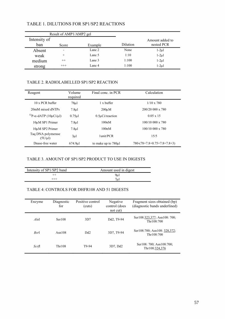
TABLE 1. DILUTIONS FOR SP1/SP2 REACTIONS
Result of AMP1/AMP2 gel Intensity of
ban Score Example Dilution Amount added to
nested PCR Absent - Lane 2 None 1-2μl
weak + Lane 5 1:10 1-2μl
medium ++ Lane 3 1:100 1-2μl
strong +++ Lane 4 1:100 1-2μl
TABLE 2. RADIOLABELLED SP1/SP2 REACTION Reagent Volume
required Final conc. in PCR Calculation
10 x PCR buffer 78μl 1 x buffer 1/10 x 780
20mM mixed dNTPs 7.8μl 200μM 200/20 000 x 780 32P-α-dATP (10μCi/μl) 0.75μl 0.5μCi/reaction 0.05 x 15
10μM SP1 Primer 7.8μl 100nM 100/10 000 x 780
10μM SP2 Primer 7.8μl 100nM 100/10 000 x 780 Taq DNA polymerase
(5U/μl) 3μl 1unit/PCR 15/5
Dnase-free water 674.9μl to make up to 780μl 780-(78+7.8+0.75+7.8+7.8+3)
TABLE 3. AMOUNT OF SP1/SP2 PRODUCT TO USE IN DIGESTS
TABLE 4: CONTROLS FOR DHFR108 AND 51 DIGESTS
Intensity of SP1/SP2 band Amount used in digest ++ 9μl
+++ 7μl
Enzyme Diagnostic for
Positive control (cuts)
Negative control (does
not cut)
Fragment sizes obtained (bp) (diagnostic bands underlined)
AluI Ser108 3D7 Dd2, T9-94 Ser108:323,377; Asn108: 700; Thr108:700
BsrI Asn108 Dd2 3D7, T9-94 Ser108:700; Asn108: 328,372; Thr108:700
ScrfI Thr108 T9-94 3D7, Dd2 Ser108: 700; Asn108:700; Thr108:324,376
57

11. FURTHER INFORMATION
Further information on radiation safety can be found in numerous sites on the web. Many universities in the United Kingdom and United Sates of America have excellent radiation protection sites, often with radiation safety manuals which you can read and/or download. You can easily find these using a search engine, and terms such as ‘radiation safety manual’. Examples of sites: http://www.le.ac.uk/safety/documents/radiation/ University of Leicester, United Kingdom: a comprehensive set of individual documents covering the UK regulations and guidelines http://www.utoronto.ca/safety/IonRad/IonRadMan.htm The Radiation safety manual of the University of Toronto, Canada http://www.gla.ac.uk/services/radiationprotection/ The webpages of the University of Glasgow Radiation Protection Service. Contains the course notes for a radiation protection course, as well as schemes of work, etc. The International Atomic Energy Agency has many publications available for download covering the regulations for the use of radioactive materials. http://www.iaea.org/Publications/index.html The Basic Safety Standards Directive The International Atomic Energy Agency (IAEA) has a number of publications regarding general safety standards for ionizing radiation work. These are available from :
Sales and Promotion Unit International Atomic Energy Agency Wagramerstrasse 5, P.O. Box 100, A-1400 Vienna, Austria E-mail: [email protected] Web site: www-pub.iaea.org/MTCD/publications/publications.asp/
Other useful publications can be obtained (see Refs [63–66])
58

APPENDICES


Appendix I
TERMS USED TO DESCRIBE RADIOACTIVITY Decay Constant is the statistical probability of decay (disintegration) of each radioactive atom in a group of identical atoms per unit time. For example, if Decay constant = 0.01s-1, each atom has a chance of 0.01% of decaying in 1 second. Half Life is the time for the activity to be reduced to half its initial value. Energy Levels associated with radioactive decay are measured in electron volts (eV). Isotopes emitting alpha particles are normally the most energetic (4–8 MeV), whilst beta and gamma emitters have decay energies less than 3 MeV, e.g. 32P. Magnitude of radioactivity is measured in Becquerels (Bq), which is the SI unit, or Curies (Ci). One Becquerel is equal to one disintegration per second. Curie is the quantity of radioactive material in which the number of nuclear disintegrations per minute is the same as that in 1g of Radium i.e. 2.2X10¹². Useful conversions: 37 kBq = 37 000 Bq = 1 μCi 37 MBq = 37 000 000 Bq = 1 mCi 1 μCi = 37 kBq = 2.22 x 10⁶ dpm 1 mCi = 37 MBq = 2.22 x 10⁹ dpm (dpm = disintegrations per minute) Specific Activity is the amount of radioisotope present per mass of the compound it is incorporated into. It may be expressed as disintegration rate, count rate, or Curies per unit mass of mixture (grams or moles). Gray (Gy) – a measurement of absorbed dose (energy) deposited in any medium by any type of radiation. Sievert (Sv) – For protection purposes, the term Dose Equivalent has been introduced. The Dose Equivalent is expressed in Sieverts (Sv) and dose limits that are given in this unit are a measure of human absorbed dose, with corrections made for the type of radiation. In biological systems, the same degree of damage is not necessarily produced by the same absorbed dose of different types of radiation. Until recently, other units for absorbed radiation were used: RAD - unit of absorbed dose (100 rad = 1 Gy) REM - unit of dose equivalent (100 rem = 1 Sv)
61

App
endi
x II
CH
AR
AC
TE
RIS
TIC
S O
F R
AD
ION
UC
LID
ES
CO
MM
ON
LY
USE
D IN
MO
LE
CU
LA
R B
IOL
OG
Y L
AB
OR
AT
OR
IES
Nuc
lide
Hal
f life
Ty
pe o
f ra
diat
ion
emitt
ed
Max
imum
(a
vera
ge) b
eta
ener
gy (k
eV)
Bet
a pa
rticl
e ra
nge
in a
ir B
eta
parti
cle
rang
e in
w
ater
/tiss
ue
Shie
ldin
g re
quire
d M
onito
ring
met
hod
Pers
onal
dos
imet
ry
3 H
12.3
yea
rs
Bet
a 18
.6 (6
) 0.
6cm
0.
0006
cm
Non
e Sc
intil
latio
n co
untin
g N
one
requ
ired,
urin
e bi
oass
ay
14C
57
30 y
ears
B
eta
156
(49)
24
cm
0.28
cm
0.3c
m P
ersp
ex*
Sc
intil
latio
n co
untin
g,
Thin
end
-win
dow
G
eige
r-M
ülle
r det
ecto
r
Non
e re
quire
d
35S
87.4
day
s B
eta
167
(49)
30
cm
0.3c
m
0.3c
m P
ersp
ex*
Sc
intil
latio
n co
untin
g,
Thin
end
-win
dow
G
eige
r-M
ülle
r det
ecto
r
Non
e re
quire
d
32P
14.3
day
s B
eta
1710
(700
) 60
0cm
0.
8cm
1c
m P
ersp
ex*
Gei
ger-
Mül
ler d
etec
tor,
liqui
d sc
intil
latio
n R
equi
red-
film
/TLD
/OSL
ba
dge,
fing
er ri
ngs i
f hig
h do
se to
fing
ers
33P
25.4
day
s B
eta
249
(85)
90
cm
0.06
cm
0.3c
m P
ersp
ex*
liqui
d sc
intil
latio
n, G
M
dete
ctor
N
one
requ
ired
* or
Ple
xigl
ass,
acry
lic, o
r sim
ilar p
last
ic m
ater
ial
62

Appendix III
SAMPLE FORMS III.1. Radioactive Material Permit Chief Scientist:
Dates:
Institution: Telephone: Email:
Type of Isotope: Chemical Form: Total Activity: Total Activity per Exp. (approx.):
Briefly describe the experimental protocol involving isotopes:
Describe your safety and handling procedures:
Describe your protocol for decontamination in the event of a spill:
63

Describe your protocol for containment, storage and removal of both liquid and solid isotope waste (benchcoat, gloves, etc.):
How do you intend to monitor the area of isotope use over the course of your work (i.e. Geiger counter)?
Please list other personnel to be covered under this permit Name Institution Type of Training
Home Institution's Radiation Safety Officer Name Institution Title Approval
Date
64

III.2. Ionizing Radiation Authorization Permit Chief Scientist Applying for Permit
Department Institution Phone Number Email
Description of Project
Radioactive Materials Limits Maximum Quantities (mCi) Locations on
Nuclide Total Possession
Use Per Experiment
Experimental Protocol # if any
Authorized Radiation Worker Wet Lab Dry Lab Other
Approval and Certification We approve this ionizing radiation use as described and is subject to the precautions listed. Radiation Safety Officer Date
We certify that all work will be as described and will be performed in accordance with the precautions listed. Permitted User Date
Health Physics Committee Chairman Date
Permitted User’s Supervisor Date
65

III.3. Room use log form ROOM USE SHEET: IMPORTANT! Please fill in for every visit Date Time
in Time out
Task performed Approx amount isotope used
User
IONIZING RADIATION : CONTROLLED AREA
66

III.4. Accident report form
Accidental Radiation Exposure Incidents Log Date/time of incident: ………………………………………………….. People involved (full names) …………………………………………….……. Part of body exposed to radiation? …………………………………………….……. Length of exposure (approx): ………………………………………………….. Describe below what happened and why you think the incident occurred What can you do in future to avoid this happening again?
IONIZING RADIATION : CONTROLLED AREA
67

III.5. Radioactivity stock record form Unsealed Radionuclide Source records Radionuclide stock record Radionuclide / Half-life
Ordered by:
Initial activity (Bq) Where stored: Date of receipt Vial identification
number
Chemical formula Batch number Date Workers
name Activity Dispensed (MBq)
Activity Remaining (MBq)
Waste To Drain (MBq)
Solid Waste (MBq)
Scintillant Waste (MBq)
Other Waste (Specify) (MBq)
68

Appendix IV
LABELLING
IV.1. Door label for controlled area
DANGER
RADIATION RISK
IONISING RADIATION : CONTROLLED AREA Area supervisor: John Smith, Room 330, Tel. Extn. 3344 Institute Radiation supervisor: Anne Asmah, Room 206, Extn. 5543 Isotopes present: 32P Maximum activity: 18.5MBq (500μCi)
STRICTLY NO ENTRY TO UNAUTHORIZED PERSONNEL
The following personnel have received training and personal dosimeters and are permitted to enter this facility: Sisi Rodriguez, John Smith
69

IV.2. Label for door of supervised radiation area
IONIZING RADIATION: SUPERVISED AREA Area supervisor: Name, Room Nº, Extension Institute Radiation supervisor: Name, Room Nº, Extension
70

IV.3. Label for freezer or refrigerator containing radioactive material
DANGER RADIATION RISK
Liquid radiation source: 32P
Isotopes present: 32P Maximum activity: 18.5MBq (500μCi)
71

IV.4. Miscellaneous labels
SINK FOR RADIOACTIVE MATERIALS
SINK FOR NON-RADIOACTIVE
MATERIALS ONLY
72

Appendix V
SAMPLE SCHEME OF WORK (to be signed by radiation officer)
This scheme of work was prepared by a laboratory using [(γ-32P) ATP-labelled oligonucleotide probes for dot-blot hybridization work. The name of the laboratory and people involved have been removed. SAFETY PROCEDURE FOR THE RADIOISOTOPE CONTAINMENT LABORATORY Suite 121 consists of three rooms. Two have been designated as supervised areas and one as a controlled area for use of 32P. These areas are identified by door labels. Entry to the controlled area is restricted to people who have received training in the handling of radioactive material. There is an area supervisor who is responsible for the day-to-day activity and monthly monitoring. An institute radiation supervisor is to be appointed. He/she will liaise between (institute name) and (country name). BEFORE ENTERING THE CONTROLLED ROOM: (1) Wear a long-sleeved lab coat and full shoe. (2) Always wear your DOSIMETERS; hang badges on the breast pocket and wear rings on
the finger closest to and directly facing the source. IN THE CONTROLLED ROOM (1) Wear two pairs of gloves always- if the top pair gets contaminated you can remove and
still be protected. (2) Sign in by filling in the appropriate form. (3) Switch off air conditioner before working. (4) Using the monitor, check the working area and apparatus for any contamination before
you start. (5) Make sure you’ve got everything you need before you start (e.g. tips, clean bag in
rubbish bin). (6) Always transport the source in the beta-shielded storage box and pipette the source
behind the beta shields to minimize personal exposure. (7) Always use forceps to lift vials containing the source. (8) Carry out work on a surface covered with absorbent material or in a tray of sufficient
capacity to contain any spillage. (9) Monitor working area regularly as you work. (10) Clean all spills of radioactive materials appropriately and decontaminate all
contaminated materials or dispose off as radioactive waste. Wipe contaminated surface repeatedly with a suitable detergent to remove traces of activity.
(11) Store all radioactive materials in a labelled fridge at 4oC or at –20oC, in shielded storage containers (acrylic/Perspex or lead).
(12) Never move anything from the radiation area without monitoring first for contamination.
SPECIFIC INSTRUCTIONS FOR STOCK RADIOACTIVE SOURCE (1) Upon receipt of the material check the package for any leakage and transfer the lead
shielded vial to the beta storage box and place at the appropriate temperature (+4 oC or -20 oC)
(2) Fill in a new record sheet for this material giving details of batch number, activity, etc.
73

(3) When aliquoting from the stock transfer the beta box containing the vial to behind the beta shield before removing the source from the box
(4) Read the manufacturers instructions on how to open the vial. For Amersham Redivue nucleotides, remove the screw cap by turning in anticlockwise direction. Attach a Gilson tip to a pipette and insert the tip into the hole at the top of the splash guard. Remove the splash guard by vertically withdrawing the pipette. The splash guard will remain attached to the pipette tip. Using a pipette in the other hand the appropriate amount of material can be removed from stock and the splash guard then replaced. The tip can be ejected from the pipette and the tip removed from the splash guard using forceps
(5) Record on the sheet the amount (μl) and activity (MBq) removed from stock and calculate the amount remaining. Estimate the activity (MBq), which will end up in liquid or solid waste and enter onto form.
WASTE DISPOSAL (a) Liquid
(1) Store all liquid waste in clearly labelled Winchester bottles kept behind the beta shields. Label the bottle with the date that it became full.
(2) Dispose of waste by pouring it down the drain after 10 half lives or when activity becomes very low (background level). Flush with copious amounts of water.
(3) Estimate the amount of radioactivity in the liquid by summing up the daily estimates recorded on the appropriate form.
(b) Solid
(1) Put all solid waste such as tissues, tips, columns, etc. in a small polyethylene bag and keep in the big acrylic/Perspex storage box for 140 days. This can then be sent to the incinerator if it reaches the background levels.
(2) Estimate the amount of radioactivity in the solid waste in the same way as was done for the liquid waste.
BEFORE LEAVING THE CONTROLLED ROOM (1) Using the counter, check the working area and all the apparatus used, making sure
there is no contamination. Decontaminate where necessary. (2) Check hands and coat. (3) Hands should be washed before leaving the room. (4) Sign out by filling appropriate forms. EMERGENCY PROCEDURES Should there be a major spill, first get the person involved to remove all clothing that came into contact with source. If bare skin is contaminated wash with soap and water. If large areas of the body are contaminated the person should shower till levels drop to background. Contaminated clothing e.g. laboratory coat should be put in a plastic bag labelled with date and stored behind the beta shield for ten half live or until the levels drop to background.
Liquid spills to the working area should be mopped up with tissue and the area cleaned with detergent and tissue until levels drop to background.
74

MONITORING The Geiger Muller type monitor will be calibrated once a year by the radiation protection board (country name). Batteries will be checked monthly during the area monitoring test.
Personal monitoring Every person must have his or her own TLD badge and ring. Sharing is not allowed. New workers can obtain these by contacting the institute radiation supervisor. Please give at least a weeks notice. Badges and rings will be collected on a monthly basis and sent to the Radiation Protection Board (country name) for assessment of dose received. Period between assessments is subject to review. It may be extended to quarterly or longer Workers with high exposure levels will be interviewed in order to ascertain how and why this happened and given advice on how to avoid it in future or the person can be retrained if necessary. Any incident of contamination of a worker should be recorded on the incident sheet so as to cross check with the exposure. Area monitoring Every person will monitor the controlled area before, during and after their work. On a monthly basis the area supervisor will monitor radiation levels in the controlled and supervised areas and readings recorded. RECORD KEEPING All record sheets (area monitoring, incident sheet, radioactive material record sheet and room usage log record) will be kept in an easily accessible file.
75


REFERENCES
[1] SAMBROOK, J., FRITSCH, EF., MANIATIS, T., EDS. Molecular cloning: a laboratory manual. 2nd edition. Cold Spring Harbor Laboratory, New York, USA (1989).
[2] SINCLAIR, B. Hot pursuit. Isotopic labels still have their place in DNA hybridization. Scientist 14 (2000) 22.
[3] ZITZ, JC., MCLACHLIN, CM., TATE, JE., MUTTER, GL., CRUM, CP. Restriction fragment length polymorphism analysis of isotype-labeled polymerase chain reaction-amplified human papillomavirus DNA combines sensitivity with built-in contaminant detection. Mod Pathol 7 (1994) 407–11.
[4] VALENTINE-THON, E., STEINMANN, J., ARNOLD, W. Detection of hepatitis B virus DNA in serum with nucleic acid probes labelled with 32P, biotin, alkaline phosphatase or sulphone. Mol Cell Probes 5 (1991) 299–305.
[5] MOLDEN, DP., NAKAMURA, RM., SUZUKI, H., GREER, S., PERGOLIZZI, RG. et al. Comparison of radio-labelled DNA probe with a nonisotopic probe for assay of serum hepatitis B virus DNA. Clin Physiol Biochem 3 (1985) 174–83
[6] GOSZTONYI, G., TERBORG, M. In situ hybridization histochemistry in the diagnosis of viral infections in the central nervous system. Acta Histochem Suppl. 42 (1992) 123–30.
[7] VICTOR, TC., LEE, H., CHO, SN., JORDAAN, AM., VAN DER SPUY, G., et al. Molecular detection of early appearance of drug resistance during Mycobacterium tuberculosis infection. Clin. Chem. Lab. 40 (2002) 876-881
[8] BARLET, V., COHARD, M., THELU, MA., CHAIX, MJ., BACCARD, C., et al. Quantitative detection of hepatitis B virus DNA in serum using chemiluminescence: comparison with radioactive solution hybridization assay. J Virol Methods 49 (1994) 141–51.
[9] BUTTERWORTH, LA., PRIOR, SL., BUDA, PJ., FAOAGALI, JL., COOKSLEY, WG. Comparison of four methods for quantitative measurement of hepatitis B viral DNA. J Hepatol 24 (1996) 686–91.
[10] IGLOI, GL. Strategies for introducing non-radioactive labels during the automated sequence analysis of nucleic acids. Electronic J Biotechnol 1 (1998) No. 1. http://www.ejb.org.
[11] COURSEY, BM. Needs for radioactivity standards and measurements in the life sciences. Appl. Radiat Isot. 52 (2000) 609–14.
[12] DOUKHAN, L., DELWART, E. Population genetic analysis of the protease locus of human immunodeficiency virus type 1 quasispecies undergoing drug selection, using a denaturing gradient-heteroduplex tracking assay. J Virol 75 (2001) 6729-36.
[13] ZISCHLER, H., NANDA, I., SCHAFER, R., SCHMID, M., EPPLEN, JT. Digoxigenated oligonucleotide probes specific for simple repeats in DNA fingerprinting and hybridization in situ. Hum Genet 82 (1989) 227–33.
[14] PENG, H., DU, M., JI, J., ISAACSON, PG., PAN, L. High-resolution SSCP analysis using polyacrylamide agarose composite gel and a background-free silver staining method. Biotechniques 19 (1995) 410–4.
[15] COCKERILL, FR. 3rd. Genetic methods for assessing antimicrobial resistance. Antimicrob Agents Chemother 43 (1999) 199-212.
[16] VICTOR, T., VAN HELDEN, P., WARREN, R. Prediction of Drug Resistance in M.tuberculosis: Molecular mechanisms, tools and applications. IUBMB Life 53 (2002) 231–7.
[17] GRANJEAUD, S., BERTUCCI, F., JORDAN, BR. Expression profiling: DNA arrays in many guises. BioEssays 21 (1999) 781–790.
77

[18] ADAM, W., BEINHAUER, A., MOSANDL, T., SAHA-MOLLER, C., VARGAS, F. et al. Photobiological studies with dioxetanes in isolated DNA, bacteria, and mammalian cells. Environ Health Perspect 88 (1990) 89-97.
[19] EPE, B., MULLER, E., ADAM, W., SAHA-MOLLER, CR. Photochemical DNA modifications induced by 1,2-dioxetanes. Chem Biol Interact 85 (1992) 265–81
[20] VAN RIE, A., WARREN, RM., BEYERS, N. et al. Transmission of a multidrug-resistant Mycobacterium tuberculosis strain resembling "strain W" among noninstitutionalized, human immunodeficiency virus-seronegative patients. J Infect Dis 180 (1999) 1608–15.
[21] VICTOR, TC., JORDAAN, AM., VAN RIE, A. et al. Detection of mutations in drug resistance genes of Mycobacterium tuberculosis by a dot-blot hybridization strategy. Tuber Lung Dis 79 (1999) 343–348.
[22] ABDEL-MUHSIN, AA., RANFORD-CARTWRIGHT, L., MEDANI, AR., AHMED, S., SULEIMAN, S. et al. Detection of mutations in Plasmodium falciparum dihydrofolate reductase (dhfr) gene by dot-blot hybridisation.. Am J Trop Med Hyg 67 (2002) 24–7.
[23] RANFORD-CARTWRIGHT, LC., JOHNSTON, KL., ABDEL-MUHSIN, AM., KHAN, BK. BABIKER, HA. Critical comparison of molecular genotyping methods for detection of drug resistant Plasmodium falciparum. Trans R Soc Trop Med Hyg 96 (2002) 568–72.
[24] COCKERILL, FR 3RD,, UHL, JR., TEMESGEN, Z. et al. Rapid identification of a point mutation of the Mycobacterium tuberculosis catalase-peroxidase (katG) gene associated with isoniazid resistance. J Infect Dis 171 (1995) 240-5.
[25] KREMER, K., VAN SOOLINGEN, D., FROTHINGHAM, R., HAAS, WH., HERMANS, PW. et al. Comparison of methods based on different molecular epidemiological markers for typing of Mycobacterium tuberculosis complex strains: interlaboratory study of discriminatory power and reproducibility. J Clin Microbiol. 37 (1999) 2607–18.
[26] PICARD, B. Molecular epidemiology of large bacterial endemics in Sub-Saharan Africa. Bull Soc Pathol Exot 93 (2000) 219–23.
[27] DUJARDIN, JC., VICTOIR, K., DE DONCKER, S., GUERBOUJ, S., AREVALO, J., LE RAY, D. Molecular epidemiology and diagnosis of Leishmania: what have we learnt from genome structure, dynamics and function? Trans R Soc Trop Med Hyg 96 (2002) Suppl 1:S81-6.
[28] HUBNER, G., BATTMER, K., LINK, H. DNA fingerprint analysis in acute leukemias. Leuk Lymphoma 17 (1995) 27–33.
[29] JENKINS, GJ., WILLIAMS, GL., BEYNON, J., YE, Z., BAXTER, JN., PARRY, JM. Restriction enzymes in the analysis of genetic alterations responsible for cancer progression. Br J Surg 89 (2002) 8–20.
[30] TOMAIUOLO, R., SPINA, M., CASTALDO, G. Molecular diagnosis of cystic fibrosis: comparison of four analytical procedures. Clin Chem Lab Med 41 (2003) 26–32.
[31] DEAN, M., WHITE, MB., AMOS, J., GERRARD, B., STEWART, C. et al. Multiple mutations in highly conserved residues are found in mildly affected cystic fibrosis patients. Cell 61 (1990) 863–70.
[32] TELENTI, A., IMBODEN, P., MARCHESI, F. et al. Detection of rifampicin-resistance mutations in Mycobacterium tuberculosis. Lancet 341 (1993) 647-50.
[33] HEYM, B., ALZARI, PM., HONORE, N., COLE, ST. Missense mutations in the catalaseperoxidase gene, katG, are associated with isoniazid resistance in Mycobacterium tuberculosis. Mol.Microbiol 15 (1995) 235–245.
78

[34] KOELEMAN, JG., STOOF, J., BIESMANS, DJ., SAVELKOUL, PH., VANDENBROUCKE-GRAULS, CM. Comparison of amplified ribosomal DNA restriction analysis, random amplified polymorphic DNA analysis, and amplified fragment length polymorphism fingerprinting for identification of Acinetobacter genomic species and typing of Acinetobacter baumannii. J Clin Microbiol 36 (1998) 2522–9.
[35] JANSSEN, P., COOPMAN, R., HUYS, G., SWINGS, J., BLEEKER, M. et al. Evaluation of the DNA fingerprinting method AFLP as an new tool in bacterial taxonomy. Microbiology 142 (1996) 1881–93.
[36] SAVELKOUL, PHM., AARTS, HJM., DE HAAS, J., DIJKSHOORN, L., DUIM,OTSEN, M. et al. Amplified-fragment length polymorphism analysis: the state of an art. J Clin Microbiol 37 (1999) 3083–3091.
[37] MASIGA, DK., TAIT, A., TURNER, CM. Amplified restriction fragment length polymorphism in parasite genetics. Parasitol Today 16 (2000) 350–3.
[38] SMOOKER, PM., COTTON, RG. The use of chemical reagents in the detection of DNA mutations. Mutat Res 288 (1993) 65–77.
[39] GOLDRICK, M. RNAse cleavage-based methods for mutation/SNP detection, past and present. Hum Mutat 18 (2001) 190-204.
[40] RODRIGUES, NR., ROWAN, A., SMITH, ME., KERR, IB., BODMER, WF. et al. p53 mutations in colorectal cancer. Proc Natl Acad Sci U S A 87 (1990) 7555–9.
[41] CRISTINA, J., MOYA, A., ARBIZA, J., RUSSI, J., HORTAL, M. et al. Evolution of the G and P genes of human respiratory syncytial virus (subgroup A) studied by the RNase A mismatch cleavage method. Virology 184 (1991) 210–8.
[42] RESCH, W., PARKIN, N., STUELKE, EL., WATKINS, T., SWANSTROM, R. A multiple-site-specific heteroduplex tracking assay as a tool for the study of viral population dynamics. Proc Natl Acad Sci U S A 98 (2001) 176–81.
[43] DOUKHAN, L., DELWART, E. Population genetic analysis of the protease locus of human immunodeficiency virus type 1 quasispecies undergoing drug selection, using a denaturing gradient-heteroduplex tracking assay. J. Virol. 75 (2001) 6729–36.
[44] FRANCA, LT., CARRILHO, E., KIST, TB. A review of DNA sequencing techniques. Q Rev Biophys 35 (2002) 169–200.
[45] BRODER, S., VENTER, JC. Sequencing the entire genomes of free-living organisms: the foundation of pharmacology in the new millennium. Annu Rev Pharmacol Toxicol. 40 (2000) 127-132. Review.
[46] KOSHY, BT., ZOGHBI, HY. The CAG/polyglutamine tract diseases: gene products and molecular pathogenesis. Brain Pathol 7 (1997) 927–42.
[47] IRVINE, RA., YU, MC., ROSS, RK., COETZEE, GA. The CAG and GGC microsatellites of the androgen receptor gene are in linkage disequilibrium in men with prostate cancer. Cancer Res 55 (1995) 1937–40.
[48] HILL, AV. Genetic susceptibility to malaria and other infectious diseases: from the MHC to the whole genome. Parasitology 112 (1996) Suppl:S75-84.
[49] NAIDOO, R., CHETTY, R. The application of microsatellites in molecular pathology. Pathol Oncol Res 4 (1998) 310–5.
[50] CHRISTENSEN, M., SUNDE, L., BOLUND, L., ORNTOFT, TF. Comparison of three methods of microsatellite detection. Scand J Clin Lab Invest 59 (1999) 167–77.
[51] NICK, H., GILBERT, W. Detection in vivo of protein-DNA interactions within the lac operon of Escherichia coli. Nature 313 (1985) 795-8.
[52] SALZ, HP., JOST, JP. Genomic footprinting with Taq polymerase. Nature 332 (1989) 277.
[53] MUELLER, PR., WOLD, B. In vivo footprinting of a muscle specific enhancer by ligation mediated PCR. Science 246 (1989) 780–6.
79

[54] ROEST, PA., ROBERTS, RG., VAN DER TUIJN, AC., HEIKOOP, JC., VAN OMMEN, GJ. et al. Protein truncation test (PTT) to rapidly screen the DMD gene for translation terminating mutations. Neuromuscul Disord 3 (1993) 391–4.
[55] POWELL, SM., PETERSEN, GM., KRUSH, AJ., BOOKER, S., JEN, J. et al. Molecular diagnosis of familial adenomatous polyposis. N Engl J Med 329 (1993) 1982–7.
[56] DAVEY, MR., BLACKHALL, NW., POWER, JB. Chloramphenicol acetyl transferase assay. Methods Mol Biol 49 (1995) 143–8.
[57] BOSWORTH, N., TOWERS, P. Scintillation proximity assay. Nature 341 (1989) 167–8
[58] SAVOYSKY, E., AKAMATSU, K., TSUCHIYA, M., YAMAZAKI, T. Detection of telomerase activity by compination of TRAP method and scintillation proximity assay (SPA). Nucleic Acids Res 24 (1996) 1175–6
[59] DUGGAN, DJ., BITTNER, M., CHEN, Y., MELTZER, P., TRENT, JM. Expression profiling using cDNA microarrays. Nat Genet 21 (1999) Suppl 10-4.
[60] CHEN, X., FEI, Z., SMITH, LM., BRADBURY, EM., MAJIDI, V. Stable-isotope-assisted MALDI-TOF mass spectrometry for accurate determination of nucleotide compositions of PCR products. Anal Chem 71 (1999) 3118–25.
[61] GYGI, SP., RIST, B., GERBER, SA., TURECEK, F., GELB, MH., AEBERSOLD, R. Quantitative analysis of complex protein mixtures using isotope-coded affinity tags. Nat Biotechnol 17 (1999) 994–9.
[62] PANG, J., MODLIN, J., YOLKEN, R. Use of modified nucleotides and uracil-DNA glycosylase (UNG) for the control of contamination in the PCR-based amplification of RNA. Mol Cell Probes 6 (1992) 251–6.
[63] FOOD AND AGRICULTURE ORGANIZATION OF THE UNITED NATIONS, INTERNATIONAL ATOMIC ENERGY AGENCY, INTERNATIONAL LABOUR ORGANISATION, OECD NUCLEAR ENERGY AGENCY, PAN AMERICAN HEALTH ORGANIZATION, WORLD HEALTH ORGANIZATION, International Basic Safety Standards for Protection against Ionizing Radiation and for the Safety of Radiation Sources, Safety Series No. 115 (1996).
[64] INTERNATIONAL ATOMIC ENERGY AGENCY. Radiation Protection and the Safety of Radiation Sources: A Safety Fundamental. Safety Series No. 120, IAEA, Vienna (1996).
[65] INTERNATIONAL ATOMIC ENERGY AGENCY, Occupational Radiation Protection Safety Guide, IAEA Safety Standards Series No. RS-G-1.1, IAEA Vienna (1999).
[66] INTERNATIONAL ATOMIC ENERGY AGENCY, Legal and Governmental Infrastructure for Nuclear, Radiation, Radioactive Waste and Transport Safety Safety Requirements, IAEA Safety Standards Series No. GS-R-1, IAEA, Vienna (2000).
[67] ABDEL-MUHSIN, A.A., RANFORD-CARTWRIGHT, L.C., MEDANI, A.R., AHMED, S., SULEIMAN, S., KHAN, B. et al. Detection of mutations in the Plasmodium falciparum dihydrofolate reductase (dhfr) gene by dot-blot hybridization: a potential method for epidemiological surveys of drug resistance genes. American Journal of Tropical Medicine & Hygiene 67 (2002) 24–27.
[68] ROPER, C., PEARCE, R., BREDENKAMP, B., GUMEDE, J., DRAKELEY, C., MOSHA, F., CHANDRAMOHAN, D. SHARP, B. Antifolate antimalarial resistance in southeast Africa: a population-based analysis. The Lancet 361 (2003) 1174–81.
[69] RANFORD-CARTWRIGHT, L.C., JOHNSTON, K.L., ABDEL-MUHSIN A.A., KHAN, B. & BABIKER, H.A. Critical comparison of molecular genotyping methods for detection of drug resistant Plasmodium falciparum. Transactions of the Royal Society of Tropical Medicine & Hygiene 96 (2002) 568–572.
80

[70] DURAISINGH, M.T., CURTIS, J., WARHURST, D.C. Plasmodium falciparum: Detection of polymorphisms in the Dihydrofolate reductase and Dihydropteroate synthetase genes by PCR and restriction digestion. Experimental Parasitology 89 (1998) 1–8.
[71] SHAIO, M.F., WANG, P., LEE, C.S., SIMS, P.F.G. & HYDE, J.E. Development and comparison of quantitative assays for the dihydropteroate synthetase codon 540 mutation associated with sulfadoxine resistance in Plasmodium falciparum. Parasitology 116 (1998) 203–210.
81


IAEA PUBLICATIONS ON MOLECULAR DIAGNOSIS, NUCLEAR MEDICINE AND RADIOSAFETY
2006 INTERNATIONAL ATOMIC ENERGY AGENCY, Nuclear Medicine Resources
Manual, IAEA, Vienna (2006) (STI/PUB/1198). 2000 INTERNATIONAL ATOMIC ENERGY AGENCY. Legal and Governmental
Infrastructure for Nuclear, Radiation, Radioactive Waste and Transport Safety, Safety Requirements, IAEA Safety Standards Series No. GS-R-1, IAEA, Vienna (2000).
1999 INTERNATIONAL ATOMIC ENERGY AGENCY. Occupational Radiation
Protection Safety Guide, IAEA Safety Standards Series No. RS-G-1.1. IAEA, Vienna (1999).
1998 INTERNATIONAL ATOMIC ENERGY AGENCY. In Vitro Radionuclide
Techniques in Medical Diagnosis, IAEA-TECDOC-1001, IAEA, Vienna (1998). 1996 FOOD AND AGRICULTURE ORGANIZATION OF THE UNITED NATIONS,
INTERNATIONAL ATOMIC ENERGY AGENCY, INTERNATIONAL LABOUR ORGANISATION, OECD NUCLEAR ENERGY AGENCY, PAN AMERICAN HEALTH ORGANIZATION, WORLD HEALTH ORGANIZATION, International Basic Safety Standards for Protection against Ionizing Radiation and for the Safety of Radiation Sources, Safety Series No. 115 (1996).
1996 INTERNATIONAL ATOMIC ENERGY AGENCY. Radiation Protection and the
Safety of Radiation Sources: A Safety Fundamental, Safety Series No. 120, IAEA, Vienna (1996)
1994 INTERNATIONAL ATOMIC ENERGY AGENCY. Radionuclides in Molecular
Technology for Diagnosis of Communicable Diseases, IAEA-TECDOC-748, IAEA, Vienna (1994).
83


CONTRIBUTORS TO DRAFTING AND REVIEW Dar, L. All India Institute of Medical Sciences, New Delhi, India Fernandes, O. FIOCRUZ, Rio de Janeiro, Brazil García Aguirre, L.1 Universidad de la República, Montevideo, Uruguay Khan, B. International Atomic Energy Agency Mbacham, W. University of Yaounde, Cameroon Thakur, R. Institute of Human Behaviour and Allied Sciences,
New Delhi, India; Ranford-Cartwright, L.2 University of Glasgow, United Kingdom Victor, T.3 University of Stellenbosch, Cape Town, South Africa
Consultants Meetings
Vienna, Austria: 1–4 June 2004; 7–11 June 2004
1 Contributed Figures 1–8. 2 Contributed Figures 9–10, 12, 14–15, 17, 19 and 21–24. 3 Contributed Figures 11, 13, 16 and 18.
85