orbit sprinkler system designer installation guide · orbit® sprinkler system designer ... parts...
TRANSCRIPT

Orbit® Sprinkler System Designer™
InstallatIon GuIde
53251-34 rA

Questions? 1.800.651.0686 orbitonline.com/sprinklerdesign
ORBIT® SPRINKLER SySTEm DESIGNER™ InstallatIon GuIde
For your information Orbit Irrigation Products, Inc. (“Orbit®”) has established its Terms of Use for OrbIT SPrInkler SySTem DeSIgner™.
dIsClaIMeRThe OrbIT SPrInkler SySTem DeSIgner™ Application (“application”) and OrbIT SPrInkler SySTem DeSIgner™ Output (“output”) are provided by Orbit® on an “as is” basis. you, as the user, agree that the use of the application and output is at the user’s own risk. neither Orbit®, nor its affiliates, officers, directors, employees, consultants or agents warrant that the application will be uninterrupted or error-free. nor do they make any warranty as to the output that may be obtained from the use of the application, or as to the accuracy, reliability or currency of any information, content, or service provided. Orbit® may withdraw the application and its content at any time without further claim by the user.
The sole intent of the application and output is to provide homeowners with a fast, efficient method by which to design and purchase an outdoor cold water sprinkler system for personal installation and use. The output represents one possible way of many to install a sprinkler system. This software, the resulting schematics, parts list, and assembly guide are intended to be used as a help guide only. The user is responsible for reviewing the design and methods of installation with a qualified local expert prior to installation. Although every effort has been made to ensure that the application and output produce accurate designs, parts lists, and assembly instructions, the user is responsible for verifying all details, dimensions, quantities, methods, and conformance to local codes, and shall be solely responsible for the same. While the application and output follows generally accepted irrigation design and installation practices, state and local codes and practices vary widely, and Orbit® shall be held harmless for any and all errors. The user is solely responsible for learning the methods of installation, verifying code and permit requirements, including those related to backflow prevention, and checking for all possible utilities and hazards prior to digging or trenching.
The application and output cannot and do not presume to take into account site specific factors such as slope, soil type, vegetation type, local climate or property peculiarities such as location of property lines, utilities, structures, window wells, stair wells, fences, footings, foundations, driveways, sidewalks, trees, shrubs, pools,
ponds or other physical factors which may materially affect design, installation, performance, safety, or code requirements for a sprinkler system. The user is solely responsible for identifying, evaluating and addressing all risks associated with designing, installing and maintaining any system which derives from the use of the application or output.
OrbIT® mAkeS nO rePreSenTATIOnS Or WArrAnTIeS OF Any kInD, eXPreSS Or ImPlIeD, AS TO THe COnTenT Or mATerIAlS InClUDeD On THe APPlICATIOn, THe OPerATIOn OF THe APPlICATIOn, Or THe OUTPUT PrODUCeD FrOm THe APPlICATIOn. TO THe FUll eXTenT PermISSIble by APPlICAble lAW, OrbIT® eXPreSSly DISClAImS All WArrAnTIeS, eXPreSSeD Or ImPlIeD, InClUDIng, bUT nOT lImITeD TO, ImPlIeD WArrAnTIeS OF SellerS, FITneSS FOr A PArTICUlAr PUrPOSe, Or nOn-InFrIngemenT. In nO eVenT SHAll OrbIT® be lIAble FOr Any DIreCT, InDIreCT, InCIDenTAl, SPeCIAl, eXemPlAry, PUnITIVe Or COnSeQUenTIAl DAmAgeS (InClUDIng WITHOUT lImITATIOn, lOSS OF USe, lOST PrOFITS Or lOST DATA) WITHOUT regArD TO THe FOrm OF Any ACTIOn, InClUDIng bUT nOT lImITeD TO, COnTrACT, neglIgenCe, TOrT Or OTHer legAl THeOry, ArISIng FrOm THe USe OF THe APPlICATIOn Or OUTPUT.
IntelleCtual PRoPeRtY notICeOrbIT SPrInkler SySTem DeSIgner™ is a trademark of Orbit®. Orbit’s trademarks may not be used in connection with any product or service that is not Orbit’s without express written permission.
All content included in the application, including all logos, graphics, photographic images, illustrations, paintings, text and software is the sole and exclusive property of Orbit® and is protected by U.S. and international intellectual property laws. All software used on this application is the property of Orbit® or its software suppliers. The compilation of the content on this application is the exclusive property of Orbit®. Any use of this content, except for the express purpose of linking back to the application, is forbidden. Any reproduction, modification, distribution, republication or display of content is strictly prohibited.
In the event the provisions herein are void or voidable, the remainder of the terms of use shall be in full force and effect.
oRBIt sPRInKleR sYsteM desIGneR™ leGal notICe
Questions? 1.800.651.0686 orbitonline.com/sprinklerdesign
ORBIT® SPRINKLER SySTEm DESIGNER™ InstallatIon GuIde
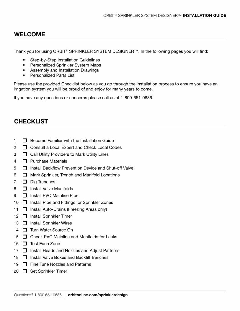
Thank you for using OrbIT® SPrInkler SySTem DeSIgner™. In the following pages you will find:
• Step-by-StepInstallationGuidelines • PersonalizedSprinklerSystemMaps • AssemblyandInstallationDrawings • PersonalizedPartsList
Please use the provided Checklist below as you go through the installation process to ensure you have an irrigation system you will be proud of and enjoy for many years to come.
If you have any questions or concerns please call us at 1-800-651-0686.
1 r become Familiar with the Installation guide
2 r Consult a local expert and Check local Codes
3 r Call Utility Providers to mark Utility lines
4 r Purchase materials
5 r Install backflow Prevention Device and Shut-off Valve
6 r mark Sprinkler, Trench and manifold locations
7 r Dig Trenches
8 r Install Valve manifolds
9 r Install PVC mainline Pipe
10 r Install Pipe and Fittings for Sprinkler Zones
11 r Install Auto-Drains (Freezing Areas only)
12 r Install Sprinkler Timer
13 r Install Sprinkler Wires
14 r Turn Water Source On
15 r Check PVC mainline and manifolds for leaks
16 r Test each Zone
17 r Install Heads and nozzles and Adjust Patterns
18 r Install Valve boxes and backfill Trenches
19 r Fine Tune nozzles and Patterns
20 r Set Sprinkler Timer
WelCoMe
CHeCKlIst

Questions? 1.800.651.0686 orbitonline.com/sprinklerdesign
ORBIT® SPRINKLER SySTEm DESIGNER™ InstallatIon GuIde
1. BeCoMe faMIlIaR WItH tHe InstallatIon GuIde
We recommend that you read through the entire Installation guide before you begin. keep track of the items not provided and make a list of those things you will need to purchase. This will help keep the number of trips back to the store to a minimum.
2. Consult a loCal exPeRt and CHeCK loCal Codes
before you begin consult a local sprinkler expert to learn the best practices for sprinkler installation in your area.
It is important that you check with your city, county, state and municipal water agencies to learn the local codes and permit requirements for sprinkler systems.
3. Call utIlItY PRovIdeRs to MaRK utIlItY lInes
Call before you dig – in most areas dial 8-1-1. We recommend you call well in advance to give the utility companies time to mark their lines on your property.
The following table shows what each color represents in most areas. Please consult the marking service provider or your utilities to better understand the color code used in your area.
unIfoRM ColoR Code
Red electric power lines, cables, conduit, and lighting cables
oRanGe Telecommunication, alarm or signal lines, cables or conduit
YelloW natural gas, oil, steam, petroleum, or other gaseous or flammable material
GReen Sewers and drain lines
Blue Drinking water
vIolet reclaimed water, irrigation and slurry lines
PInK Temporary survey markings, unknown/unidentified facilities
WHIte Proposed excavation limits or route
BefoRe You BeGIn

Questions? 1.800.651.0686 orbitonline.com/sprinklerdesign
ORBIT® SPRINKLER SySTEm DESIGNER™ InstallatIon GuIde
4. PuRCHase MateRIals
At the back of the installation guide you will find a parts list for the materials used in the design of your system. The parts specified in this list do not include the materials you will need to tie into your mainline, backflow prevention devices, or shut-off valves. Installation codes for tying into your mainline, installing backflow preventers and installing shut-offs vary considerably. Check local codes prior to installation. you may need to hire a professional to do the installation.
In addition to your custom parts list, we have provided a list of additional materials you will need for your installation.
5. Install BaCKfloW PReventIon devICe and sHut-off valve
Check your local code to determine the backflow prevention requirements for your area. you may need to hire a professional to do the installation. Following are a few examples of backflow prevention devices.
r 4" or 5" Trenching Shovel
r Trenching machine (optional)
r round-nosed Shovel
r PVC Pipe
r PVC Fittings
r PVC Primer
r PVC Cement
r 100' measuring Tape
r Sprinkler Flags
r marking Paint
r PTFe Pipe Tape
r Work gloves
r
r
r
r
r
r
BefoRe You BeGIn
double Check valve assembly Reduced Pressure Backflow Preventer
Pressure vacuum Breaker atmospheric vacuum Breaker / anti-siphon valve
5. (Cont’d)

Questions? 1.800.651.0686 orbitonline.com/sprinklerdesign
ORBIT® SPRINKLER SySTEm DESIGNER™ InstallatIon GuIde
5. Install BaCKfloW PReventIon devICe and sHut-off valve (Cont’d)
We recommend that you install a 1" Slip ball Valve immediately following the backflow prevention device.
If you are using an atmospheric vacuum breaker or anti-siphon valve, you must place he shut-off valve before the backflow prevention.
For areas where freezing conditions are a concern we recommend you install a QCV (Quick Coupling Valve) as well. This will make winterizing your sprinkler system much simpler. A QCV provides an easy way to connect an air compressor to blow out your system. The QCV also acts as a garden valve. See WInTerIZATIOn in the appendix for more details.
you should not use a QCV with an atmospheric vacuum breaker or anti-siphon valve.
1" slip PvC Ball valve(not included)
supply line
supply line
Quick Coupling valve Gear Clamp
Water flow
Water flow
PvC Risers
PvC elbows PvC tee
stake
1" sch 40 PvC (not included)
this design plan does not apply to anything before this point; homeowner is responsible for ensuring system complies with local codes including backflow prevention, etc.; consult a licensed plumber
to Manifolds
BefoRe You BeGIn
A1
Questions? 1.800.651.0686 orbitonline.com/sprinklerdesign
ORBIT® SPRINKLER SySTEm DESIGNER™ InstallatIon GuIde
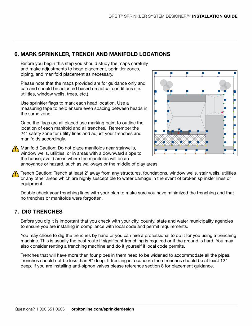
6. MaRK sPRInKleR, tRenCH and ManIfold loCatIons
before you begin this step you should study the maps carefully and make adjustments to head placement, sprinkler zones, piping, and manifold placement as necessary.
Please note that the maps provided are for guidance only and can and should be adjusted based on actual conditions (i.e. utilities, window wells, trees, etc.).
Use sprinkler flags to mark each head location. Use a measuring tape to help ensure even spacing between heads in the same zone.
Once the flags are all placed use marking paint to outline the location of each manifold and all trenches. remember the 24" safety zone for utility lines and adjust your trenches and manifolds accordingly.
manifold Caution: Do not place manifolds near stairwells, window wells, utilities, or in areas with a downward slope to the house; avoid areas where the manifolds will be an annoyance or hazard, such as walkways or the middle of play areas.
Trench Caution: Trench at least 2' away from any structures, foundations, window wells, stair wells, utilities or any other areas which are highly susceptible to water damage in the event of broken sprinkler lines or equipment.
Double check your trenching lines with your plan to make sure you have minimized the trenching and that no trenches or manifolds were forgotten.
7. dIG tRenCHes
before you dig it is important that you check with your city, county, state and water municipality agencies to ensure you are installing in compliance with local code and permit requirements.
you may chose to dig the trenches by hand or you can hire a professional to do it for you using a trenching machine. This is usually the best route if significant trenching is required or if the ground is hard. you may also consider renting a trenching machine and do it yourself if local code permits.
Trenches that will have more than four pipes in them need to be widened to accommodate all the pipes. Trenches should not be less than 8" deep. If freezing is a concern then trenches should be at least 12" deep. If you are installing anti-siphon valves please reference section 8 for placement guidance.
C

Questions? 1.800.651.0686 orbitonline.com/sprinklerdesign
ORBIT® SPRINKLER SySTEm DESIGNER™ InstallatIon GuIde
8. Install valve ManIfolds
For each valve box dig a 26" x 20" hole to the recommended depth (shown below). For best installation the valve box should run parallel to the pipe trench as shown to the right.
Add 2" of crushed rock to serve as a drainage base for the valve manifold.
Place the valve box platform and valve box on the base of crushed rock. lay a 2 x 4 across the hole to ensure the top of the valve box is level with the ground (as shown below).
Assemble all the manifolds called out on the MaInlIne MaP - example A2 - A4 . match the assembly call out with one of the following assembly drawing pages. Use the assembly drawings as your guide.
Do not make any PVC pipe or glued connections at this point. We will walk you through that in another step.
If A6 is called out on a sPRInKleR zone MaP then reference assembly A6 in the following pages for instructions on creating a drip zone valve.
Prepare the valve box platform for the manifold by removing one front knockout for each valve in the manifold. remove the side knockout that is closest to the water source connection. Place each manifold in its respective valve box platform.
side Knockout
side Knockoutfront Knockouts
2 x 4
12" standard Box and valve Platform Base
2 x 4
6" standard extension Box and valve Platform Base
freezing area non-freezing area
2" Base of Crushed RockRecommended depth 17" Recommended depth 11"
20"
26"
Questions? 1.800.651.0686 orbitonline.com/sprinklerdesign
ORBIT® SPRINKLER SySTEm DESIGNER™ InstallatIon GuIde
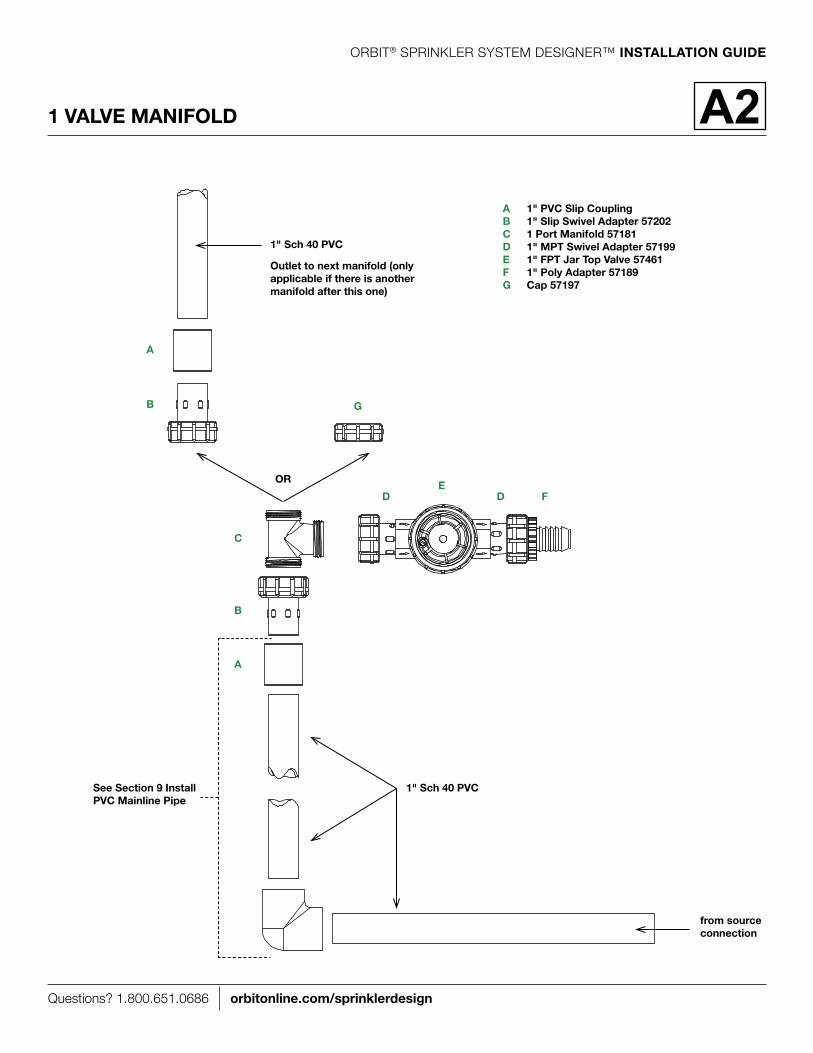
1 valve ManIfold
a 1" PvC slip CouplingB 1" slip swivel adapter 57202C 1 Port Manifold 57181d 1" MPt swivel adapter 57199e 1" fPt Jar top valve 57461f 1" Poly adapter 57189G Cap 57197
B
a
C
d d fe
G
1" sch 40 PvC
B
a
oR
outlet to next manifold (only applicable if there is another manifold after this one)
from source connection
1" sch 40 PvC see section 9 Install PvC Mainline Pipe
A2

Questions? 1.800.651.0686 orbitonline.com/sprinklerdesign
ORBIT® SPRINKLER SySTEm DESIGNER™ InstallatIon GuIde
2 valve ManIfold
a 1" PvC slip CouplingB 1" slip swivel adapter 57202C 2 Port Manifold 57182d 1" MPt swivel adapter 57199e 1" fPt Jar top valve 57461f 1" Poly adapter 57189G Cap 57197
B
a
C
d d fe
G
1" sch 40 PvC
B
a
oR
outlet to next manifold (only applicable if there is another manifold after this one)
from source connection
1" sch 40 PvC
A3
see section 9 Install PvC Mainline Pipe
Questions? 1.800.651.0686 orbitonline.com/sprinklerdesign
ORBIT® SPRINKLER SySTEm DESIGNER™ InstallatIon GuIde
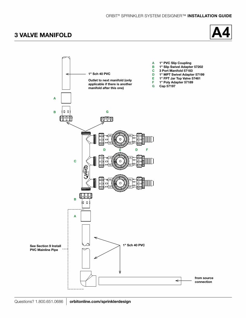
3 valve ManIfold
a 1" PvC slip CouplingB 1" slip swivel adapter 57202C 3 Port Manifold 57183d 1" MPt swivel adapter 57199e 1" fPt Jar top valve 57461f 1" Poly adapter 57189G Cap 57197
B
a
C
d d fe
G
1" sch 40 PvC
B
a
outlet to next manifold (only applicable if there is another manifold after this one)
from source connection
1" sch 40 PvC
A4
see section 9 Install PvC Mainline Pipe
Questions? 1.800.651.0686 orbitonline.com/sprinklerdesign
ORBIT® SPRINKLER SySTEm DESIGNER™ InstallatIon GuIde
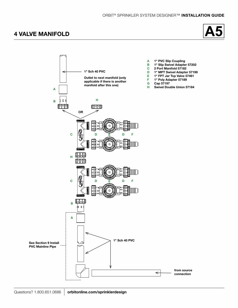
4 valve ManIfold
a 1" PvC slip CouplingB 1" slip swivel adapter 57202C 2 Port Manifold 57182d 1" MPt swivel adapter 57199e 1" fPt Jar top valve 57461f 1" Poly adapter 57189G Cap 57197H swivel double union 57184
B
a
C
H
C
d
d
d
d
f
f
e
e
H
1" sch 40 PvC
B
a
oR
outlet to next manifold (only applicable if there is another manifold after this one)
from source connection
1" sch 40 PvC
A5
see section 9 Install PvC Mainline Pipe
Questions? 1.800.651.0686 orbitonline.com/sprinklerdesign
ORBIT® SPRINKLER SySTEm DESIGNER™ InstallatIon GuIde
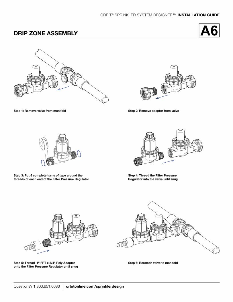
dRIP zone asseMBlY A6
step 1: Remove valve from manifold step 2: Remove adapter from valve
step 3: Put 5 complete turns of tape around the threads of each end of the filter Pressure Regulator
step 4: thread the filter Pressure Regulator into the valve until snug
step 5: thread 1" fPt x 3/4" Poly adapter onto the filter Pressure Regulator until snug
step 6: Reattach valve to manifold

Questions? 1.800.651.0686 orbitonline.com/sprinklerdesign
ORBIT® SPRINKLER SySTEm DESIGNER™ InstallatIon GuIde
9. Install PvC MaInlIne PIPe
Starting from the Water Source Connection lay and connect the PVC pipe going to the manifolds (see “Working with PVC” in the appendix of this guide for additional information).
As the mainline passes in front of a manifold complete the following steps to connect the mainline to the manifold as shown. Cut the water source pipe about 2" past the wall of the manifold hole. Prime and glue the PVC coupling, elbow, and tee to sections of PVC pipe. Carefully measure the sections of pipe before you prime and glue. Then prime and glue the coupling to manifold and the tee to water source connections at the same time. Adjust the two joints such that the PVC pipe lays flat in the bottom of the trench and the manifold sits level and is lined up to the outlets on the valve box platform.
If two manifolds need to be placed immediately next to each other follow the instructions above for the first manifold and then prime and glue the two manifolds using two PVC couplings and a length of PVC pipe.
After each manifold prime and glue PVC pipe into the open connection on the tee and continue to the next manifold.
Connect the last manifold on the mainline as shown. Follow the instructions above but instead of a tee you will use an elbow.
It is important that the mainline pipe be as deep as possible in the trenches in order to provide room for the pipes coming from each valve to the sprinkler zones.
2"
2"
A7 A8
1" PvC elbow 1" PvC tee
1" sCH 40 PvC Pipe
A7
A8
A7
A7
1" sCH 40 PvC Pipe
1" sCH 40 PvC Pipe
1" slip PvC Coupling

Questions? 1.800.651.0686 orbitonline.com/sprinklerdesign
ORBIT® SPRINKLER SySTEm DESIGNER™ InstallatIon GuIde
sidewalk/driveway/house
10. Install PIPe and fIttInGs foR sPRInKleR zones
We will now step you through the process of installing the poly pipe from the heads to the valve for each sprinkler zone (see "Working with PVC" in the appendix of this guide for additional helpful information).
Start with one sprinkler zone and install the poly pipe and fittings for that zone using the map as a guide. It is important that you finish one zone before you start another to avoid confusion. Adjust the sprinkler zone pipe and head placement to actual conditions (i.e. utilities, window wells, trees, etc.).
As we walk you through this section we will use the zone layout shown here to help you better understand each step. Install all zones following these steps, then go on to the next section.
Dig trenches for heads as needed to place the head as close as possible to the outside edges of the sprinkler zone.
1 For heads located along sidewalks, driveways, or curbs plan on spacing heads 1" to 2" from the edge or according to local code.
Use 3/4" Poly Pipe for sprinkler lines and drip lines to Drip Stub (see A22 )
Use 1/2" riser Flex Pipe for sprinkler heads Use 1" SCH 40
PVC Pipe to bring water into valves
Use 1" Poly Pipe to carry water out of valve to sprinkler lines (except in case of drip zone which uses 3/4" pipe)

Questions? 1.800.651.0686 orbitonline.com/sprinklerdesign
ORBIT® SPRINKLER SySTEm DESIGNER™ InstallatIon GuIde
sidewalk/driveway/house
sidewalk/driveway/house
Install ½" riser Flex pipe at head location. lay pipe in head trench and cut pipe to ground level at head location.
5 repeat step 5 for all remaining heads on this sprinkler zone.
6 Connect ¾" lines using ¾" x ¾" x 1" tees and 1" Poly pipe.
7
10. Install PIPe and fIttInGs foR sPRInKleR zones (Cont'd)
lay ¾" Poly pipe in the trench and install end head fittings as shown.
2 Cut the pipe at the next head location and install the fittings as shown.
3 repeat for all remaining head locations on this zone.
4

Questions? 1.800.651.0686 orbitonline.com/sprinklerdesign
ORBIT® SPRINKLER SySTEm DESIGNER™ InstallatIon GuIde
10. Install PIPe and fIttInGs foR sPRInKleR zones (Cont'd)
Install 1" elbow and cut and install pipe. Stagger the pipes from the valves so there is room for all the zones (see below).10
Install 1" tee and 1" pipe at the location of the trench that leads from this zone back to the manifold.
8 Cut pipe in line with the edge of the valve to which it will connect.
9
Do not install heads at this time. We will install heads in another section.
sidewalk/driveway/house
4" length of 1" Poly Pipe

Questions? 1.800.651.0686 orbitonline.com/sprinklerdesign
ORBIT® SPRINKLER SySTEm DESIGNER™ InstallatIon GuIde
10. Install PIPe and fIttInGs foR sPRInKleR zones (Cont'd)
Here are two examples of different zones and how they are installed. Do not install heads at this time. We will install heads in another section.
a 1" Poly teeB 3/4" x 3/4" x 1" Poly tee
a
B
a 1" Poly elbowB 3/4" x 3/4" x 1" Poly tee
a
B
4" length of 1" Poly Pipe
4" length of 1" Poly Pipe
Questions? 1.800.651.0686 orbitonline.com/sprinklerdesign
ORBIT® SPRINKLER SySTEm DESIGNER™ InstallatIon GuIde
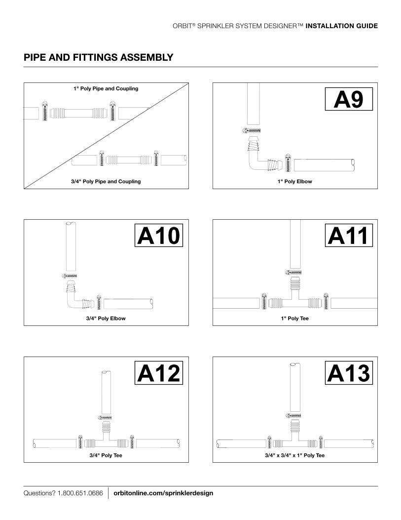
1" Poly tee3/4" Poly elbow
A11A10
3/4" x 3/4" x 1" Poly tee3/4" Poly tee
A13A12
1" Poly elbow
A9
3/4" Poly Pipe and Coupling
1" Poly Pipe and Coupling
PIPe and fIttInGs asseMBlY

Questions? 1.800.651.0686 orbitonline.com/sprinklerdesign
ORBIT® SPRINKLER SySTEm DESIGNER™ InstallatIon GuIde
A19A16 A20A17 A21A18end of lIne asseMBlY WItHout HeadInlIne asseMBlY WItHout Head
Step 1: Insert 3/4" Poly elbow into 3/4" Poly Pipe
Step 2: Insert 1/2" mPT elbow into Poly elbow
Step 3: Insert 1/2" riser Flex Pipe into elbow
Step 4: Cut 1/2" riser Flex Pipe at length to match spray head position
Do not install heads at this time.
Step 1: Cut 3/4" Poly Pipe at spray head assembly location
Step 2: Insert 3/4" Poly Tee into 3/4" Poly Pipe on both sides
Step 3: Insert 1/2" mPT elbow into Tee
Step 4: Insert 1/2" riser Flex Pipe into elbow
Step 5: Cut 1/2" riser Flex Pipe at length to match spray head position
Do not install heads at this time.
a
e
B
C
B
d
a
a
e
d
C
B
B
B
a 3/4" Poly PipeB Clamps C 3/4" x 1/2" fPt Poly elbow d 1/2" MPt x Barb elbowe 1/2" Riser flex Pipe, Cut to proper length
a 3/4" Poly PipeB Clamps C 3/4" x 1/2" fPt Poly teed 1/2" MPt x Barb elbow e 1/2" Riser flex Pipe, Cut to proper length
sPRaY Head asseMBlY

Questions? 1.800.651.0686 orbitonline.com/sprinklerdesign
ORBIT® SPRINKLER SySTEm DESIGNER™ InstallatIon GuIde
A22dRIP stuB fIttInG
See www.orbitonline.com/lib/media/DripMasterInstallationGuide.pdf for drip design options
a 3/4" Barb x 1/2" fPt Poly elbowB ClampC 3/4" Poly Piped 3/4" Poly elbow
a
C
B
B
B
dC
drip system starts here
this part of the fitting should be buried below ground

Questions? 1.800.651.0686 orbitonline.com/sprinklerdesign
ORBIT® SPRINKLER SySTEm DESIGNER™ InstallatIon GuIde
11. Install auto-dRaIns (fReezInG aReas onlY)
Where freezing is a concern we recommend you install auto-drain valves at the low spots in the system and on the downhill ends of sloping pipes. The auto drains must be at the lowest points in the line.
Do not install auto-drains on the PVC mainline.
12. Install tHe tIMeR
The timer provided can be mounted indoor or outdoor. For indoor installation refer to the diagram below and the next page. For outdoor installation use a licensed professional electrician.
outdooR InstallatIonexterior Wallexterior Wall
IndooR InstallatIon
a sprinkler WireB 1/2" Conduit nippleC Conduitd Junction Boxe elbow
Use a licensed professional electrician for outdoor installations.
aB
C
C
e
aBB
C
C
C
d

Questions? 1.800.651.0686 orbitonline.com/sprinklerdesign
ORBIT® SPRINKLER SySTEm DESIGNER™ InstallatIon GuIde
12. Install tHe tIMeR (Cont'd)
Use the mounting template (included) to mark the mounting screw location on the wall. See Figure 1
Install a no. 8 screw (included) into wall in the upper template location. leave the screw head protruding 1/8" (3mm) from wall. Use expanding anchors (included) in plaster or masonry, if necessary, for a secure hold.
Slip the timer over protruding screw (using keyhole slot in back of timer). See Figure 2
Drive a no. 8 screw through one of the two pre-formed holes located in lower back cabinet to secure timer to the wall. See Figure 2
Keyhole
Pre-formedmounting holes
No. 8 Screw
Wall
1/8"
MOUNTING TEMPLATEGABARIT D`INSTALLATIONGUIA DE COLGAR
4.17”(106 mm)
p 801 295 9820f 801 951 5815
www.fl uid-studio.net
1065 South 500 WestBountiful, Utah 84010
proof no: 3date: 10.05.07
des: SM spck: SM
job no: 07WTM005259
client: Orbit
sku: 57880
upc: ? ????? ????? ?
fi le name: 07WTM00525957880-04 rA.indd
software: Illustrator CS2
colors
additional instructions:··
crop colornon printing
PMS????
PMS????
colornon printing
PMS????
Registration
K
Printers are responsible for meeting print production requirements. Any changes must be approved by the client and Fluid Studio. printed piece must meet
designated specifi cations
on this form.
dimensions:
fl at: w: 9" h: 7"
fi nished: w 9" d: 0" h 7"
© 2007 Fluid Studio. This work is the property of Fluid Studio, and cannot be used, reproduced or distributed in any way without their express permission.
figure 1: use Mounting template (included) figure 2: Hang timer on screw using keyhole
RESET
PROGRAM
RAIN DELAY
A23

Questions? 1.800.651.0686 orbitonline.com/sprinklerdesign
ORBIT® SPRINKLER SySTEm DESIGNER™ InstallatIon GuIde
13. Install sPRInKleR WIRes
run the wire from the timer to each manifold using the existing trenches. Use the WIRInG MaP and the diagrams below as a guide. The wire provided is rated for direct burial but you may chose to run the wire inside a conduit to prevent future damage to the wire.
lay sprinkler wire as deep as possible in trenches from the timer to each manifold
At the manifold remove 4" to 5" of the outer insulation and about 1" of insulation from each individual wire (Figure 1)
Use a wire nut to connect one wire from each valve and the white wire from the sprinkler wire (Figure 2)
Use a wire nut to connect the remaining wire on the first valve to one of the colored wires from the sprinkler wire. repeat this step until all valves in the manifold are connected (Figure 3)
Insert each wire nut into the corresponding cavity inside the “easy Wire” organizer, slide the mounting bracket onto the organizer and attach to the manifold (Figure 4)
At the timer remove 4" to 5" of the outer insulation and about 1" of insulation from each individual wire (Figure 1)
Connect the wires from the valves to the timer by inserting the white wire(s) into the common terminal and each one of the colored wires into one of the station terminals labeled 1, 2, 3, etc.
To release a wire from a terminal push the tab upward then gently pull the wire out.
5
6
7
8
1
2
3
4
figure 1 figure 2 figure 3 figure 41"
4"- 5"
station terminals
Common terminals
Push tab upward to release

Questions? 1.800.651.0686 orbitonline.com/sprinklerdesign
ORBIT® SPRINKLER SySTEm DESIGNER™ InstallatIon GuIde
14. tuRn tHe WateR souRCe on
make sure the bleed screw on all the valves is in the closed position (turn clockwise to close). Slowly turn the mainline water source on. make sure all shut-off points prior to the valves are in the on position.
Some of the valves may come on briefly. If they do not shut off in a few seconds check that the bleed screw is turned clockwise until it stops. If the valve remains open shut off the water source and check that the valves are installed correctly. Check to make sure the arrows on the valves point in the direction of flow.
15. CHeCK PvC MaInlIne and ManIfolds foR leaKs
Once the valves have pressure behind them and they are all off check the manifold connections and the PVC pipe for leaks.
16. test eaCH zone
Using the timer manually test each sprinkler zone. Check the valves, pipes, and fittings for leaks. This is also the step in which you flush any debris (i.e. dirt and rocks) out of the system. make sure each head location is flowing freely.
17. Install Heads and nozzles and adJust PatteRns
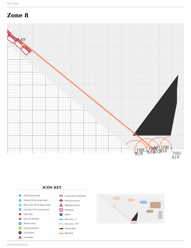
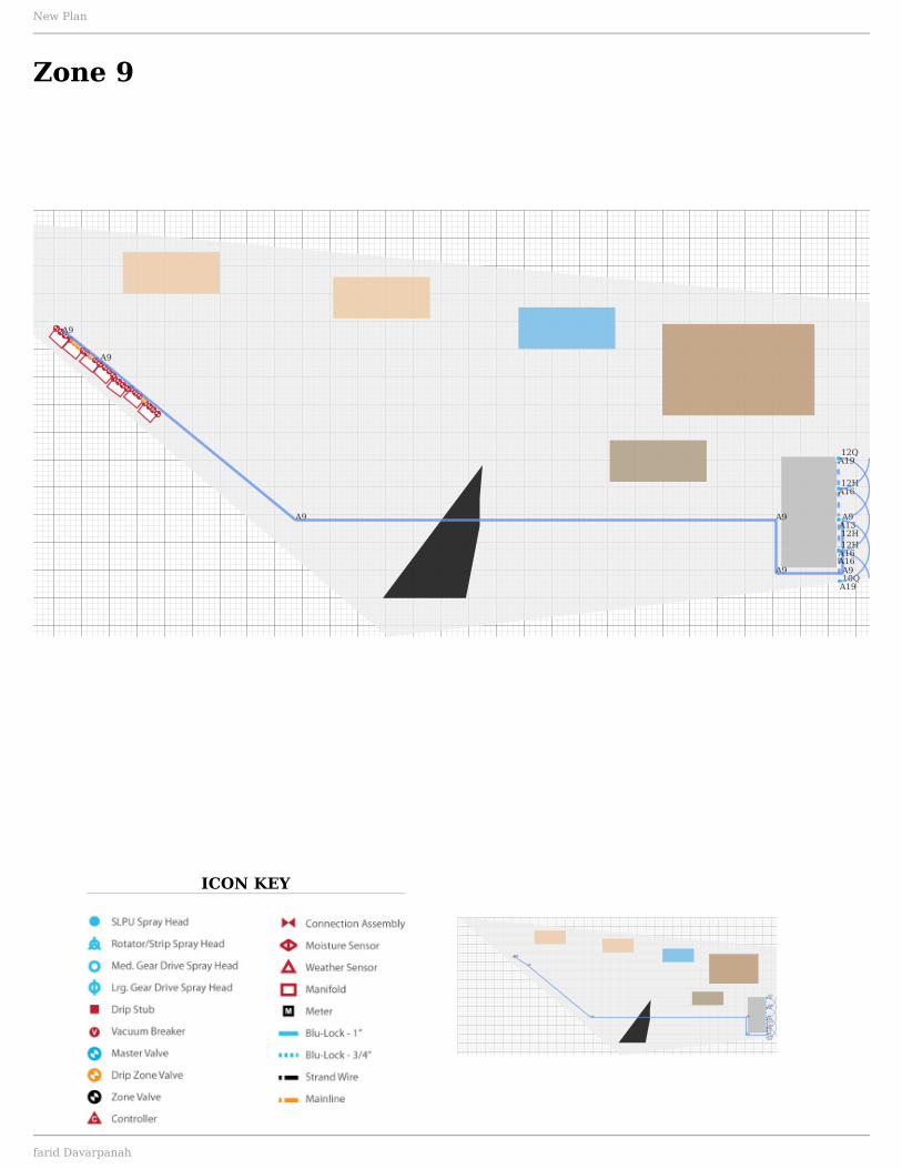
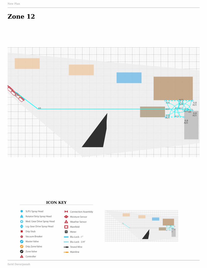
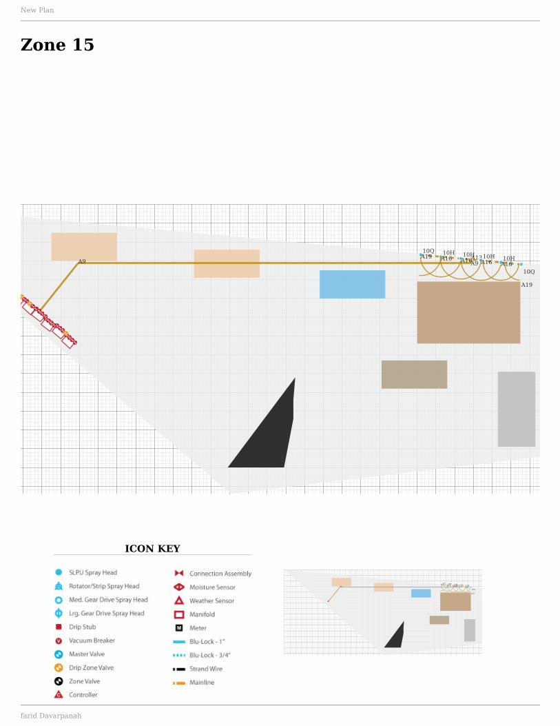
Install the heads, fittings and nozzles one zone at a time using the sPRInKleR zone MaPs and the following assembly pages as a guide. match the nozzles called out on the maps to the nozzle tables on the following page. For instance the map may show a19 | 10H; this tells you to look at assembly A19 on the next page and the 10H nozzle which is blue. make preliminary adjustments to the nozzles then turn on that sprinkler zone manually to check for leaks around the heads and to make additional adjustments to the nozzle spray patterns.
Bleedscrew

Questions? 1.800.651.0686 orbitonline.com/sprinklerdesign
ORBIT® SPRINKLER SySTEm DESIGNER™ InstallatIon GuIde
match the nozzle called out on the maps to the corresponding head nozzle chart
Step 1: Insert mPT elbow into spray head and tighten until snug.
Step 2: Insert street elbow into mPT elbow.
a 4" spray HeadB voyager II Gear driveC saturn Iv Gear drived 1/2" fPt x 1/2" MPt elbowe 3/4" fPt x 3/4" MPt elbowf 1/2" MPt x Barb elbowG 3/4" MPt x Barb elbow
Do not overtighten. Do not use pipe tape.
step 1
step 2
d
f
a
nozzle
4Q, 4H, 4T, 4F yellow
8Q, 8H, 8T, 8F green
10Q, 10H, 10T, 10F blue
12Q, 12H, 12T, 12F brown
step 1
step 2
e
G
B
nozzle
V1.0 1.0 gPm
V2.0 2.0 gPm
V3.0 3.0 gPm
V4.0 4.0 gPm
A19A16
step 1
step 2
d
f
C
nozzle
S0.5 0.5 gPm
S1.0 1.0 gPm
S1.5 1.5 gPm
S2.0 2.0 gPm
A20A17
A21A18

Questions? 1.800.651.0686 orbitonline.com/sprinklerdesign
ORBIT® SPRINKLER SySTEm DESIGNER™ InstallatIon GuIde
a16, a19 PatteRn adJustMent InstRuCtIons
A19A16
Hold the base of the nozzle with your left hand. With right hand gently turn nozzle top clockwise until it stops.
rotate the ratcheting stem until the round dot (high-lighted here in red) is lined up with the right edge of the desired spray pattern.
Hold the nozzle as shown in step 1 and gently turn the top counter-clockwise until the round dot lines up with the left edge of the desired spray pattern.
31 2

Questions? 1.800.651.0686 orbitonline.com/sprinklerdesign
ORBIT® SPRINKLER SySTEm DESIGNER™ InstallatIon GuIde
a17, a18, a20 and a21 PatteRn adJustMent InstRuCtIons
set the Pattern Before Installation:
gear drive sprinkler can be set to rotate between 40° and 360° (preset at 180°)
Turn the top of the head all the way to the left until it stops and then all the way to the right. This is the starting point for the rotation (Figure 1). Insert the plastic end of the key into the pattern adjustment hole (Figure 2). Turn clockwise to increase rotation; counterclockwise to decrease rotation. each full turn increases/decreases rotation by 90˚ (Figure 3).
Remove and Replace the nozzle:
1. To access the nozzle, remove stem from canister by unscrewing the cap and lifting the stem assembly out of the canister.
2. rest bottom of stem assembly on a hard surface or against your hand and press firmly down on the cap to compress the spring. note: The spring inside the canister is very strong.
3. Firmly grip the sprinkler stem.
4. Insert the hex (metal) end of the key into the distance adjustment slot (Figure 2).
5. Turn the screw counterclockwise until it is just clear of the nozzle.
Caution: DO nOT turn the adjustment screw too far in either direction—screw may come free of threads.
6. The nozzle can then be removed by prying outward under the nozzle.
7. Insert the correct replacement nozzle (see tables 1 and 2) and align vertically, then turn the screw back into place.
8. replace stem assembly into canister and screw cap on tightly.
9. Adjust distance if necessary (see Set the Spray Distance).
set the spray distance after Installation:
Set the spray distance with water on under system’s normal operating pressure.
Insert the hex (metal) end of the key into the distance adjustment slot (Figure 2). Turn clockwise to decrease distance; counterclockwise to increase distance.
Caution: DO nOT turn the adjustment screw too far in either direction—screw may come free of threads.
A21A18 A20A17
Table 1. VOyAger II nOZZle
IDenTIFICATIOn TAble
Pattern nozzle
Quarter 1.0
Half 2.0
Three-quarter 3.0
Full 4.0
Table 2. SATUrn IV nOZZle
IDenTIFICATIOn TAble
Pattern nozzle
Quarter 0.5
Half 1.0
Three-quarter 1.5
Full 2.0
figure 1
figure 2
or
figure 3
distance adjustment
Pattern adjustment

Questions? 1.800.651.0686 orbitonline.com/sprinklerdesign
ORBIT® SPRINKLER SySTEm DESIGNER™ InstallatIon GuIde
18. Install valve Boxes and BaCKfIll tRenCHes
Once you have verified there are no leaks install all the valve boxes for the system and backfill the trenches.
When backfilling trenches make an effort to ensure there are no large rocks resting on or against the pipes and fittings. As your soil settles with time large rocks can cause premature failure.
be careful not to cut or damage the sprinkler wires when backfilling. It is very difficult to find and repair bad wiring after the system is buried.
19. fIne tune nozzles and PatteRns
After filling in the trenches, manually turn on each sprinkler zone one at a time and fine tune the nozzle spray patterns. refer to the nozzle adjustment pages as needed.
20. set tHe tIMeR
Using the instructions booklet included with the timer set the desired program.

Questions? 1.800.651.0686 orbitonline.com/sprinklerdesign
ORBIT® SPRINKLER SySTEm DESIGNER™ InstallatIon GuIde
WoRKInG WItH PvC
Orbit Sprinkler System Designer™ specifies PVC for all mainline pipe and connections after the source connection up to and including the valve manifolds (the valves control water flowing to the individual areas or “zones” in your yard).
PVC has many good qualities. It is inexpensive, relatively easy to work with, and has a very long useful life. We recommend PVC for the constant-pressure mainline part of your system (the part going from your water source to your sprinkler valves).
PVC pipe and fittings are joined by applying primer and solvent cement to both pieces. The primer and solvent soften and melt a thin layer of PVC. Seconds after joining the pieces, the PVC hardens, forming a permanent, waterproof seal. A few caution involved with using PVC are to: 1) avoid breathing the fumes; 2) avoid letting the primer and cement come in contact with your skin; and, 3) joining the pieces quickly after priming and gluing them, since the glue sets quickly.
The materials and tools required to join PVC are:
JoInInG PvC PIPe and slIP fIttInGs
Tools required: Schedule 40 PVC pipe, fittings, 100' tape measure, marking pen, PVC pipe cutters, primer, cement, and pipe tape
Step 1. measure and cut. most fittings for a sprinkler system do not require super-precise measurements. mark the spot on the pipe where the center of the fitting will be and cut at that point with PVC cutters.
Step 2. Prime. Use the swabbing ball on the primer to spread primer over the outside of the pipe and the inside of the fitting where they will join. be careful not to spill primer on your hands.
Step 3. glue. While the primer is still wet (seconds after applying it), apply cement to the primed areas on the outside of the pipe and the inside of the fitting where they will join. be careful not to spill primer on your hands.
Step 4. Push and twist. Push the pipe into the fitting until you feel it snug against the bottom of the fitting. Turn the pipe ¼ turn in the fitting. This will spread the glue evenly and ensure a good fit. For fittings such as tees and elbows, make sure that the end of the fitting at the 90 angle is going in the right direction. If you do not orient it in the right direction, you will have to cut out the fitting and start over with a new fitting. Hold the fitting in place against the pipe for 30 seconds after joining it to ensure a good weld.
aPPendIx
Average Joint Cure Times (Pressure Test to 180 PSI)
Temperature
60°- 100° F
40°- 60° F
20°- 40° F
0°- 20° F
60% or less Humidity 1 Hr 2 Hrs 6 Hrs 8 Hrs
60% or more Humidity 1.5 Hrs 3 Hrs 9 Hrs 12 Hrs
Source: http://www.oatey.com/Plumber/FAQ.html#Q10

Questions? 1.800.651.0686 orbitonline.com/sprinklerdesign
ORBIT® SPRINKLER SySTEm DESIGNER™ InstallatIon GuIde
JoInInG PvC tHReaded fIttInGs
Tools and materials required: Fittings, pipe tape, channel locks
The most common way to join PVC threaded fittings is with PTFe or “Teflon” tape. you should never use oil-based pipe dope (typically comes in a tube) to join sprinkler fittings. Some sprinkler fittings are made of a material called AbS and oil-based pipe dope causes an adverse chemical reaction with it, leading to premature failure of the fitting or part. PTFe tape is a clean and simple way to join pipe:
Step 1. Hold the tape correctly. Always hold the tape so that the tape ribbon is going away from you and under the roll. This is not intuitive your first time, but with a little practice you will find that it makes a lot of sense.
Step 2. Wrap. Place the front piece of the tape ribbon on the second thread from the end of the fitting or pipe and hold it with your finger. Wrap the tape away from you and down and around the pipe at least two times and then start the third wrap with a 50% overlap of the previous wrap and so on until you reach the end of the threads furthest from the end of the pipe.
Step 3. Insert taped fitting into female connection and tighten until hand tight. Do not overtighten as this may damage the fitting.
Step 4. Always pressure-test all fittings prior to use. A small leak will not seal itself and over time can cause water damage.
aPPendIx

Questions? 1.800.651.0686 orbitonline.com/sprinklerdesigner
Orbit® Sprinkler System Designer™
MaPs and PaRts lIst
ICON KEY NOTES
C
2.0
1.0
1.0
2.0
3.0 1.0
2.0
3.0 4.04.0
1.0
1.5
1.51.5
0.8
1.0
2.0
1.5
0.8
1.5
0.8
0.8
1.51.5
10H10Q10Q
10H
10Q10Q
10Q 10H 10H 4Q10H 10H10Q 10H 4Q
10H10Q
10H 10H
10Q
12H
12Q
12H12H
12H
12Q
10H
10H
12Q
0.8
1.5
0.8
1.5
0.8
1.5
1.5
0.8
0.8
2.2
0.81.50.8
0.8
0.8
4H 4H
10Q4Q
4Q10H
4H
4H
10Q
10Q
10H 4Q10Q10H
4Q
10H 10H10H10Q
10Q
10H
10H10H10H
10Q
10H10Q
10H10Q 10H 10Q
10H 10Q10Q 10H
1.0
2.0
2.0
2.0
1.0
2.0
2.0 1.0
2.0
2.0
2.0
0.8
0.8
1.5
0.8
1.5
0.8
0.8
0.8
1.5 0.8
1.5
0.8
3.02.0
1.0
0.8
0.81.5
0.8
1.5
0.8
2.0
2.2 1.0
1.0
10H10H10Q10H
10Q
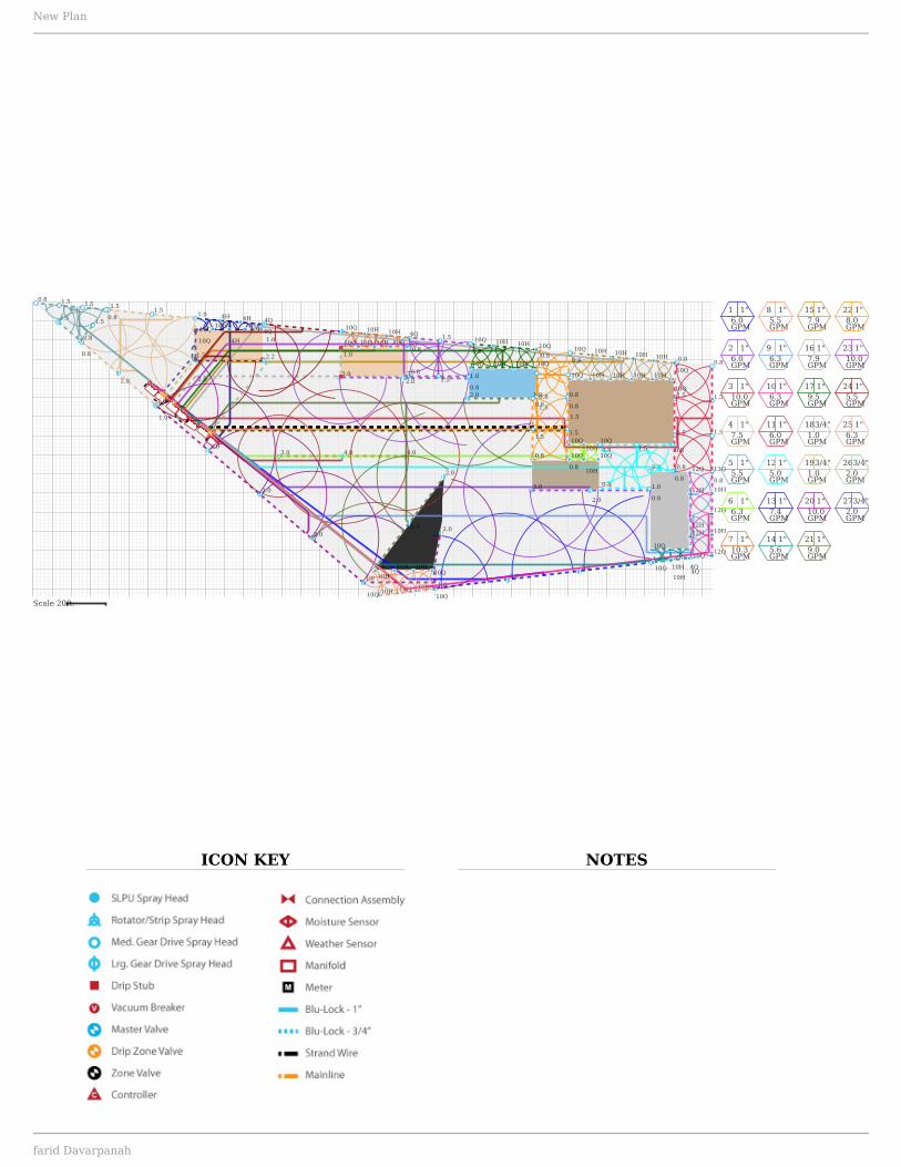
1 1"6.0GPM
2 1"6.0GPM
3 1"10.0GPM
4 1"7.5GPM
5 1"5.5GPM
6 1"6.3GPM
7 1"10.3GPM
8 1"5.5GPM
9 1"6.3GPM
10 1"6.3GPM
11 1"6.0GPM
12 1"5.0GPM
13 1"7.4GPM
14 1"5.6GPM
15 1"7.9GPM
16 1"7.9GPM
17 1"9.5GPM
183/4"1.0GPM
193/4"1.0GPM
20 1"10.0GPM
21 1"9.0GPM
22 1"8.0GPM
23 1"10.0GPM
24 1"5.5GPM
25 1"6.3GPM
263/4"2.0GPM
273/4"2.0GPM
Scale 20ft.
New Plan
farid Davarpanah

ICON KEY
A9
A9 A9A9A132.0
A17
1.0A20
1.0A20
2.0A17
Zone 1
A9
A9 A9A9A132.0
A17
1.0A20
1.0A20
2.0A17
New Plan
farid Davarpanah
ICON KEY
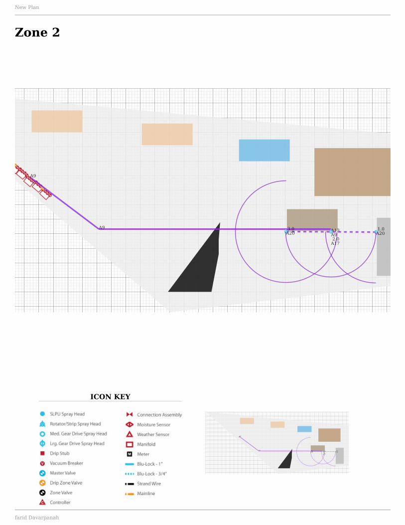
A13A9
A9
A9
3.0A20
1.0A20
2.0A17
Zone 2
A13A9
A9
A9
3.0A20
1.0A20
2.0A17
New Plan
farid Davarpanah
ICON KEY
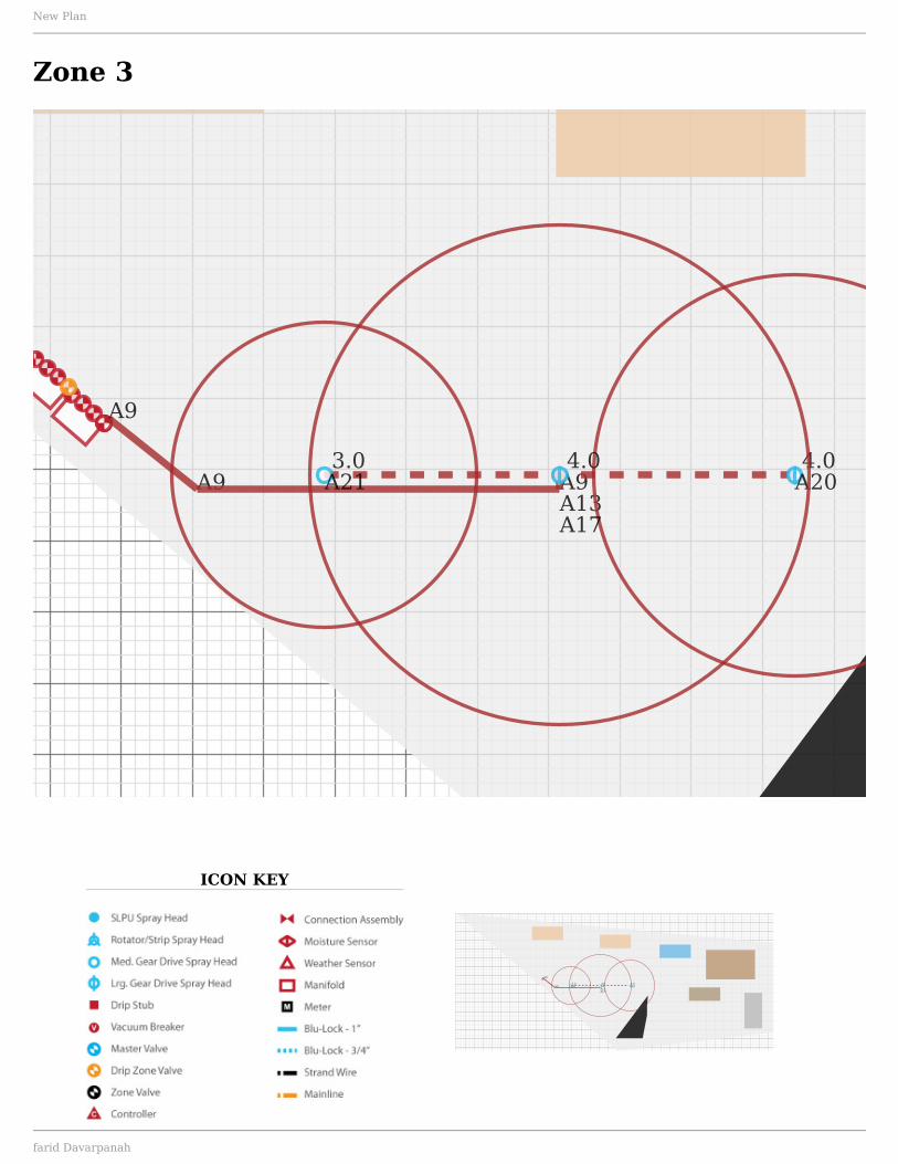
A9
A9 A9A13
3.0A21
4.0A20
4.0
A17
Zone 3
A9
A9 A9A13
3.0A21
4.0A20
4.0
A17
New Plan
farid Davarpanah
ICON KEY
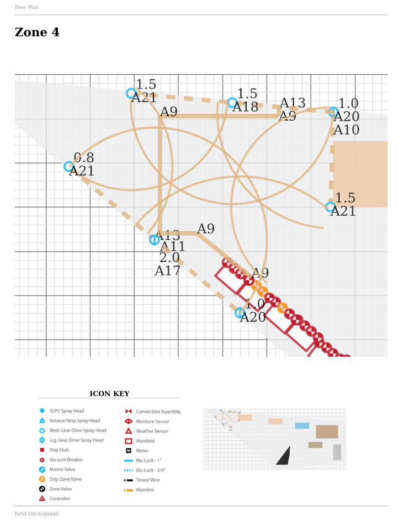
A13A11
A9
A9
A13A9A9 1.0
A20
1.5A21
A10
1.5A18
1.5A21
0.8A21
1.0A20
2.0A17
Zone 4
A13A11
A9
A9
A13A9A9 1.0
A20
1.5A21
A10
1.5A18
1.5A21
0.8A21
1.0A20
2.0A17
New Plan
farid Davarpanah

ICON KEY
A11
A9A9A13
A13
A9
A9
1.5A21
0.8A21A10
1.5A21
0.8A21
0.8A21
1.5A18
1.5A18
Zone 5
A11
A9A9A13
A13
A9
A9
1.5A21
0.8A21A10
1.5A21
0.8A21
0.8A21
1.5A18
1.5A18
New Plan
farid Davarpanah
ICON KEY
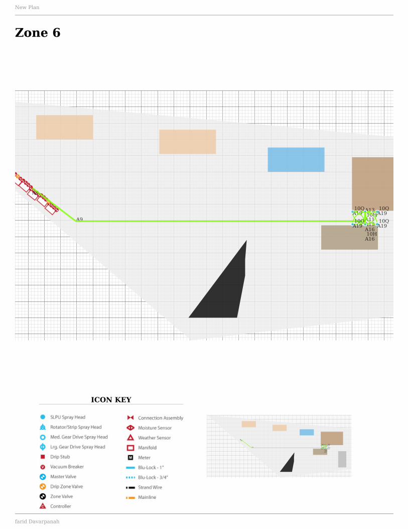
A9
A9 A11
A13
A13
10H
A16
10QA19
10QA19
10HA16
10QA19
10QA19
Zone 6
A9
A9 A11
A13
A13
10H
A16
10QA19
10QA19
10HA16
10QA19
10QA19
New Plan
farid Davarpanah

ICON KEY
A9 A11A13
A1310Q
A19 10HA16 10H
A16 4QA1910H
A1610H
A1610Q
A1910H
A16
4QA19
Zone 7
A9 A11A13
A1310Q
A19 10HA16 10H
A16 4QA1910H
A1610H
A1610Q
A1910H
A16
4QA19
New Plan
farid Davarpanah
ICON KEY
A9
A9A1310H
A19 10QA19
10HA16
10HA16
Zone 8
A9
A9A1310H
A19 10QA19
10HA16
10HA16
New Plan
farid Davarpanah
ICON KEY
A9
A9
A9 A9
A9 A9
A9A13
10QA19
12HA16
12QA19
12HA16
12H
A16
Zone 9
A9
A9
A9 A9
A9 A9
A9A13
10QA19
12HA16
12QA19
12HA16
12H
A16
New Plan
farid Davarpanah

ICON KEY
A9
A9
A9
A9
A9A1312H
A16
12QA19
10HA16
10HA16
12QA19
Zone 10
A9
A9
A9
A9
A9A1312H
A16
12QA19
10HA16
10HA16
12QA19
New Plan
farid Davarpanah

ICON KEY
A9A9
A9 A9
A11A13A9
A13
0.8A21
A10
1.5A18
0.8A21
1.5A18
0.8
A21
1.5A18
1.5A18
0.8A21
Zone 11
A9A9
A9 A9
A11A13A9
A13
0.8A21
A10
1.5A18
0.8A21
1.5A18
0.8
A21
1.5A18
1.5A18
0.8A21
New Plan
farid Davarpanah
ICON KEY
A9
A9 A11A11
A13
A13
A13A9 0.8
A21
2.2A21
0.8A21
1.5A180.8
A21
0.8A21
0.8A21
Zone 12
A9
A9 A11A11
A13
A13
A13A9 0.8
A21
2.2A21
0.8A21
1.5A180.8
A21
0.8A21
0.8A21
New Plan
farid Davarpanah

ICON KEY
A9
A11A13A13
4HA16 4H
A1610Q
A19
4QA194Q
A19
10HA16
4HA16
4HA16
10QA19
Zone 13
A9
A11A13A13
4HA16 4H
A1610Q
A19
4QA194Q
A19
10HA16
4HA16
4HA16
10QA19
New Plan
farid Davarpanah

ICON KEY
A9
A9 A9A11A13
A13
10QA19
10HA16
4Q
A19
10QA19 10H
A16
4QA19
Zone 14
A9
A9 A9A11A13
A13
10QA19
10HA16
4Q
A19
10QA19 10H
A16
4QA19
New Plan
farid Davarpanah
ICON KEY
A13A9A9
10HA16 10H
A16
10HA16
10QA19
10Q
A19
10HA16
Zone 15
A13A9A9
10HA16 10H
A16
10HA16
10QA19
10Q
A19
10HA16
New Plan
farid Davarpanah

ICON KEY
A9
A9A13 10H
A1610H
A1610H
A1610Q
A19
10HA16
10QA19
Zone 16
A9
A9A13 10H
A1610H
A1610H
A1610Q
A19
10HA16
10QA19
New Plan
farid Davarpanah

ICON KEY
A9A9
A9 A11A13A9A13 10H
A1610Q
A1910H
A1610Q
A19
10HA16 10Q
A19
10QA19 10H
A16
Zone 17
A9A9
A9 A11A13A9A13 10H
A1610Q
A1910H
A1610Q
A19
10HA16 10Q
A19
10QA19 10H
A16
New Plan
farid Davarpanah
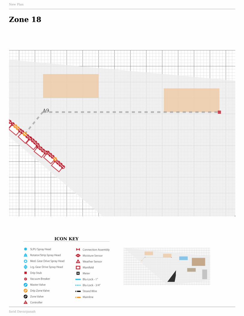
ICON KEY
A9
Zone 18
A9
New Plan
farid Davarpanah

ICON KEY
A9
Zone 19
A9
New Plan
farid Davarpanah

ICON KEY
A13A9
A9
A9
1.0A20
2.0A17
2.0A17
2.0A17
1.0A20
A10A10
A10
2.0A20
Zone 20
A13A9
A9
A9
1.0A20
2.0A17
2.0A17
2.0A17
1.0A20
A10A10
A10
2.0A20
New Plan
farid Davarpanah
ICON KEY
A9 A11 A13A9
A13A9
2.0A20
1.0A20
2.0A20
2.0A17
2.0A20
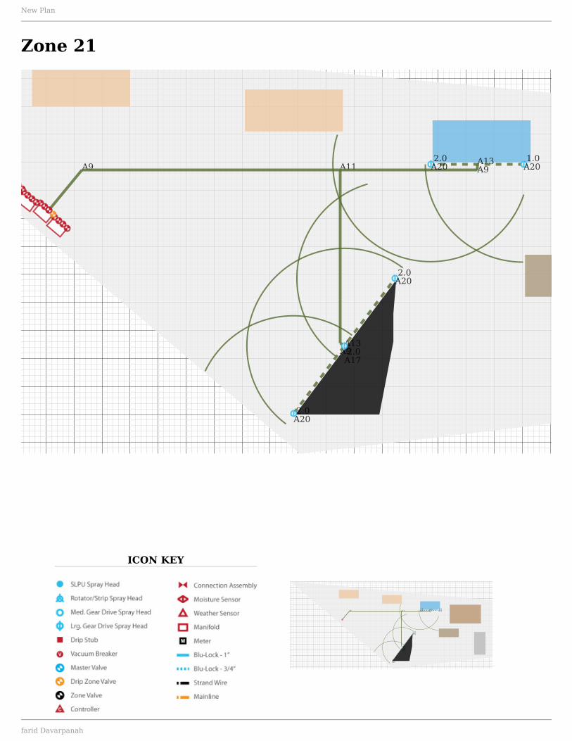
Zone 21
A9 A11 A13A9
A13A9
2.0A20
1.0A20
2.0A20
2.0A17
2.0A20
New Plan
farid Davarpanah

ICON KEY
A13A9 A11
A13
A11A13
A13
0.8A21
0.8A21
1.5
A18
0.8A21
1.5A18
0.8A21
0.8
A21A100.8
A211.5
A18
0.8A21A101.5
A18
0.8A21
Zone 22
A13A9 A11
A13
A11A13
A13
0.8A21
0.8A21
1.5
A18
0.8A21
1.5A18
0.8A21
0.8
A21A100.8
A211.5
A18
0.8A21A101.5
A18
0.8A21
New Plan
farid Davarpanah

ICON KEY
A9 A11 A11
A13
A13A9
A133.0A21 2.0
A17
1.0A200.8
A21
0.8A21 1.5
A18
0.8A21
1.5
A180.8
A21
Zone 23
A9 A11 A11
A13
A13A9
A133.0A21 2.0
A17
1.0A200.8
A21
0.8A21 1.5
A18
0.8A21
1.5
A180.8
A21
New Plan
farid Davarpanah
ICON KEY
A9A9
A11 A13A9
A13A9A9
2.0A20
2.2A21
1.0A20
1.0A20
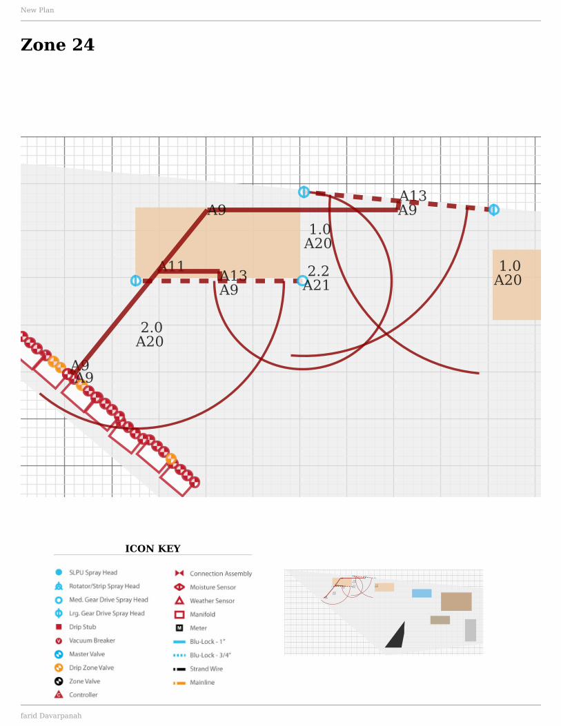
Zone 24
A9A9
A11 A13A9
A13A9A9
2.0A20
2.2A21
1.0A20
1.0A20
New Plan
farid Davarpanah
ICON KEY
A9
A9A9A13
10HA16
10H
A16
10Q
A1910H
A19A10
10QA19
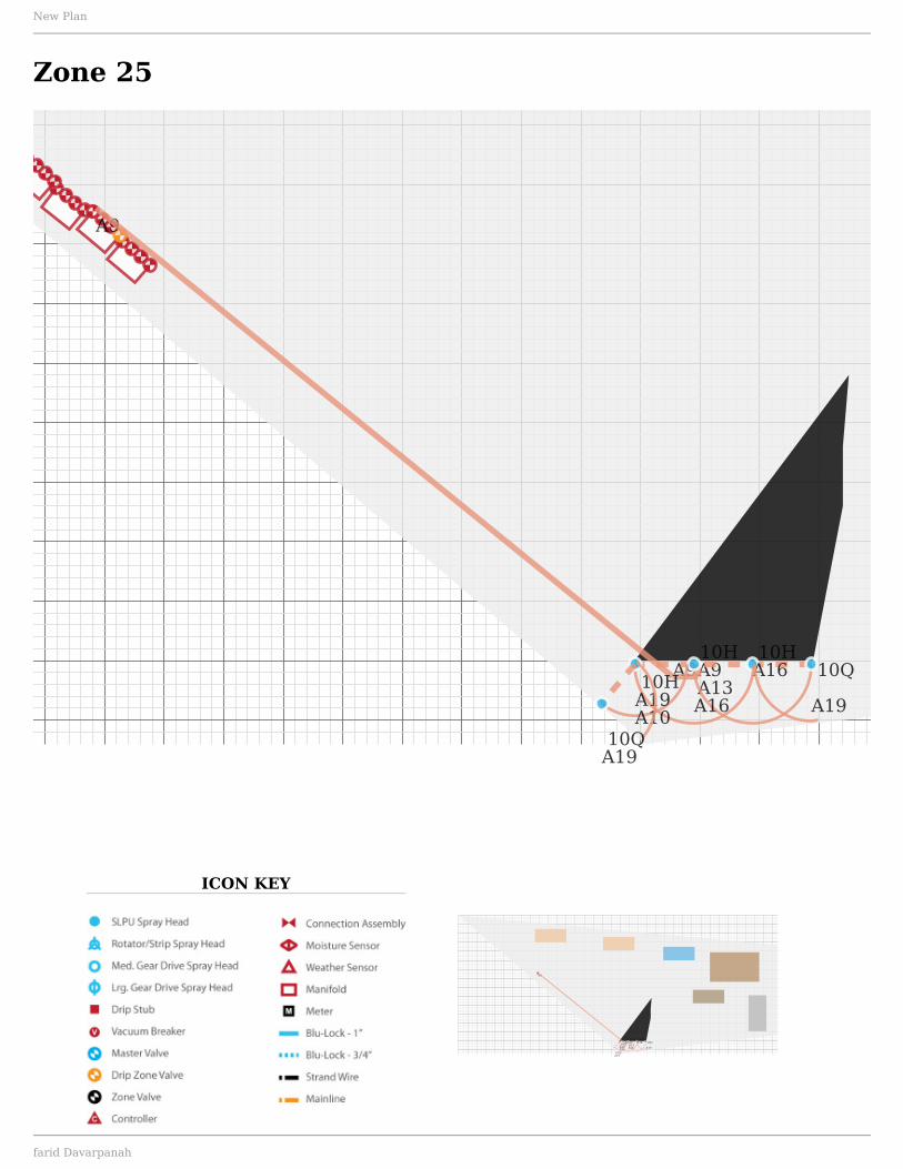
Zone 25
A9
A9A9A13
10HA16
10H
A16
10Q
A1910H
A19A10
10QA19
New Plan
farid Davarpanah

ICON KEY
A13A9
Zone 26
A13A9
New Plan
farid Davarpanah
ICON KEY
A9
A9
A13
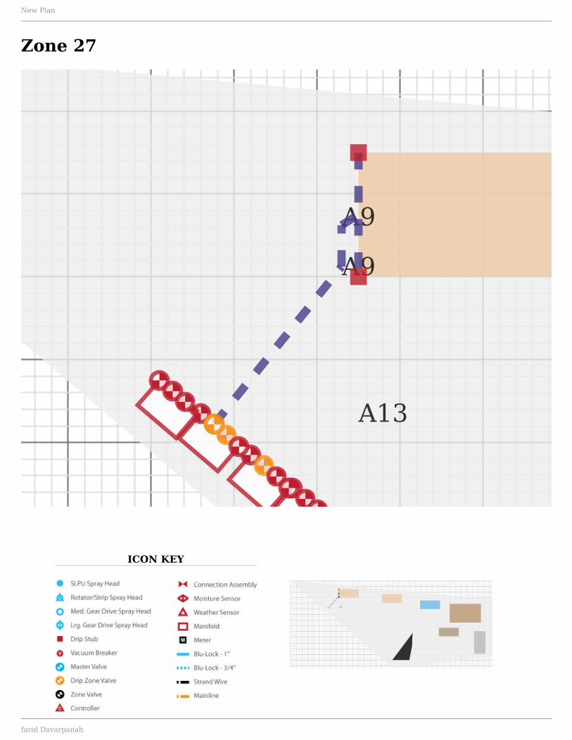
Zone 27
A9
A9
A13
New Plan
farid Davarpanah

ICON KEY
Mainline
C
New Plan
farid Davarpanah

ICON KEY
Wiring
New Plan
farid Davarpanah

ICON KEY
Trench
New Plan
farid Davarpanah

Summary
Material: $3,121.56
Price Schedule
Part # Part Name Price Quantity Item TotalFittings----- 3/4" x 1/2" FPT Poly Insert Elbow $0.83 6 $4.98----- 3/4" Poly Insert Elbow $0.78 6 $4.68----- 3/4" Slip X 1/2" FNPT PVC 90 Elbow $0.45 6 $2.70----- 3/4" Slip PVC 90 Deg Elbow $0.34 6 $2.04Gear Drive Nozzles----- 15-24' 1.5 GPM Rotor Nozzle $0.00 18 $0.00----- 15-24' 3.0 GPM Rotor Nozzle $0.00 1 $0.00----- 25-35' 2.0 GPM Rotor Nozzle $0.00 14 $0.00----- 25-35' 3.0 GPM Rotor Nozzle $0.00 2 $0.00----- 15-24' 0.8 GPM Rotor Nozzle $0.00 5 $0.00----- 15-24' 0.8 GPM Rotor Nozzle $0.00 20 $0.00----- 15-24' 2.2 GPM Rotor Nozzle $0.00 2 $0.00----- 25-35' 4.0 GPM Rotor Nozzle $0.00 2 $0.00----- 25-35' 1.0 GPM Rotor Nozzle $0.00 11 $0.00Pop-up Gear Drive Heads55179 Saturn IV Professional Gear Drive $11.99 47 $563.5355660 Voyager II Professional Gear Drive $13.99 28 $391.72Pop-Up Spray Heads54616 4 In. Eco-Spray Head with Flush Cap $3.99 69 $275.31Pop-up Spray Nozzles53580 4 Ft. Adjustable Nozzle $1.79 10 $17.9053582 10 Ft. Adjustable Nozzle $1.79 52 $93.0853583 12 Ft. Adjustable Nozzle $1.79 7 $12.53Sprinkler Timers57896/27896 6 Station Indoor/Outdoor Timer $54.99 1 $54.9957900/29892 12 Station Indoor/Outdoor Timer $86.22 1 $86.22Sprinkler Wire57093 5-Strand x 100 ft. Sprinkler Wire $29.87 15 $448.0557002 Grease Cap Kit for Splicing (Package Of 4) $4.97 15 $74.55Valve Boxes53230 Valve Box Base $12.99 7 $90.9353212 12 In. Standard Valve Box (Black/Green) $23.13 7 $161.91Valve Manifolds57250 2 Valve Inline Manifold Assembly $54.97 12 $659.6457253 3 Valve Inline Manifold Assembly $65.97 1 $65.9757184 Double Swivel Union $4.25 6 $25.5057202 3/4 In. or 1 In. Slip Swivel Adapter $3.19 7 $22.33Valves67798F 2-in-1 Pressure Regulating Drip Filter $15.75 4 $63.00
New Plan
farid Davarpanah

Subtotal: $3,121.56Tax: $0.00Total: $3,121.56
New Plan
farid Davarpanah