optimum designing of forging preform die for the h-shaped … · 2018-12-07 · introduction...
TRANSCRIPT

Journal of Modern Processes in Manufacturing and Production, Vol. 3, No.3, Summer 2014
79
Optimum Designing of Forging Preform Die for the H-shaped Parts
Using Backward Deformation Method and Neural Networks Algorithm
Afshin Naeimi1*, Mohsen Loh Mousavi2, Ali Eftekhari2
1 MSc. Student of Department of Mechanical Engineering, Islamic Azad University of Khomeini Shahr. *E-mail of corresponding author: [email protected].
2 Assistant Professor, School of Engineering, Department of Mechanical Engineering, Islamic Azad University of Khomeini Shahr
Received: January 23, 2014; Accepted: April 21, 2014 Abstract In a closed die forging process, it is impossible to form complex shapes in one stage, and thus it becomes necessary to use preform dies. In the present study, Backward Deformation Method and FE simulation via ABAQUS software has been used in order to design preform die of the H-shaped parts. In the Backward Deformation Method, the final shape of the part is considered as a starting point and using a specific method, a plastic returning path is predicted. Afterwards, using FE results obtained by simulation of the forging process, an artificial neural network is designed to predict the material behavior under various conditions and for different kinds of preform to select optimum preform dies. Keywords: Forging Preform Die, Backward Deformation Method, ABAQUS, Artificial Neural Network
1. Introduction Forging is one of the oldest methods of forming. Due to fine graining without cavities, unified properties, and the high strength of the produced structure, this process, in comparison with foundry and machining processes, has significantly attracted the attention of researchers and manufacturers. In closed die forging, the solid between the two parts, on which the final form of the part is stamped, is deformed. In this method, the part is deformed in a closed cavity under high pressure in order to fill the die space which is identical to the form of the final part. What is definite in designing this process is the form of the final part and type of the material. Given this information, the designer has to design a process to produce the part with the desired form and properties regarding time and cost limitations. For most forging processes, the fillets have simple forms. If the form of the final part is complicated, the fillet cannot be transformed into the final form through only one stage of deformation. In order to avoid issues such as inappropriate flux of the material, great forces imposed on the die, and inappropriate filling of the die, the part is deformed in several steps using preform dies before being placed in the main die. The number of preform steps can be calculated by ascertaining the complexity factor of the form of the final part. In industry, the optimum preform is usually obtained on the basis of experience, individual skill, practical experiments, and simulation of the process. The most important factor in designing the preform die is filling of the final die, even if other parameters such as plastic strain and imposed forces are not optimized. One common method for

Optimum Designing of Forging Preform Die for the H-shaped Parts Using Backward Deformation…, pp.79-96
80
determining the preform of H-shaped cross sections is the Brukhanov and Rebelsky [2] method. They divided H-sections into two groups based on the ratio of the height of the wall to its width, and proposed a preform for each group. Chamouard [3] offered another method for determining the preform of sections with high walls and narrow passages which also comprises H-sections. Thomas [4] divided the preform of H-sections into three groups based on the ratio of the height of the wall to its width. With the emergence of computer and numerical methods, traditional methods of designing preform were advanced and the steps of trial and error were made using simulation. This reduces the costs and long time required by various designing and experimenting with preform dies. Since the shape of the final part and the characteristics of the fillet as well as the features of the final die are given, a technique called backward deformation uses the information on the final part in order to design the preform and achieve the optimal shape. Backward deformation is presented by developing the restricted components of non-linear problems analyses such as forming the metals with high deformation. In this manner, for multi-step forging, the final shape of every step is regarded as the primary shape of the next step. This process is used to predict the shape of the part in every step of plastic returning. Backward deformation was first developed by Hwang and Kobayashi [5] for rolling processes. Then this method was used for designing preform dies in forging the dies with plane strain. Biglari et al. [6] developed backward deformation using fuzzy decision-making for determining the new borders of the part based on the geometry and plastic deformation of the part. This process was proposed for axisymmetric parts in forging. In this method, the die moves backward during the reverse process. The nodes on the part which are in contact with the die begin to separate. This is important to predict which node separates first. To do so, a fuzzy logic is used for decision making. The fuzzy logic in this manner is based on the uniform residual stress, reduction of possible imperfections of forging in the part, deviation of plastic stress, and the average minimum work. Then, the optimal preform die is selected using optimization of designing process. Qingbin et al. [7] proposed a new method for designing the preform by combining the two methods of limited element and extended limit element. Having defined a shape factor, Tomov and Radev [8] calculated its impact in pre-production steps and the required force for forging. Using multi-layered neural networks, Kim [9] developed a new method based on neural networks, by which one can calculate the final shape of the part on the basis of the degree of filling the die. Using neural network technique and genetic algorithm, Sedighi et al. [10] obtained optimal preform dies for a given model. Lee et al. [11] proposed a method for producing preform dies for axisymmetric parts using electric field theory and neural network. In this study, they investigated shape complexity and its effects on preform die. Castro et al. [12] optimized the form and variables of hot forging using genetic algorithm and limited components solution. Ko et al. [13] presented a new method for designing preform die for multi-step forging with regard to brittle fracture restriction. In their study, the preform dies were optimized using artificial neural networks. Tang et al. [14] optimized preform dies based on the neural network response surface methodology to obtain the structure of the response surface and to solve non-linear equations. A review of the previous works reveals that no comprehensive method has yet been presented to obtain optimal preform die for parts with various section shapes. Therefore, the present study

Journal of Modern Processes in Manufacturing and Production, Vol.3, No.3, Summer 2014
81
proposes a comprehensive method for designing preform dies using backward deformation and by completing the method offered by Biglari et al. [6]. Then, a method will be presented for the selection of optimal preform die by giving an appropriate structure of neural network. In order to investigate the proposed method, various types of preform dies for a sample H-shape part are obtained using this method. Afterwards, the required information on neural network is obtained by simulating the process of forging. Having determined the appropriate structure, the neural network will predict the behavior of the material in various forms with various preforms. Finally, the optimal preform dies are selected based on this prediction. The criteria for choosing the optimal preform die include manufacturing perfect parts with the least load of fillet, full filling of the die, least plastic stress, and the least required force for forging. In order to investigate the reliability of the prediction of the designed neural network, optimal models were simulated by the limited element software, and by comparing the results, the accuracy of the proposed neural network was scrutinized. 2. Material and Methods 2.1 Backward deformation The principles of this method, which was first used by Biglari et al. [6] to predict deformation in forging, are discussed below:
Figure. 1. A scheme of the die and the elementary raw part
1. The die should first be placed in its lowest level which is the end of the process. The raw
part should be in the beginning of the process. 2. The surface of the die and the primary part should be divided by equal number of
elements, and the coordinates of all nodes should be obtained (Figure1). 3. The corresponding nodes on the die and the part are connected to each other and the
corresponding lines are drawn. 4. Coordinates of the nodes are placed in equations (1) and (2); then the coordinates of the
preform nodes are obtained:
�� � �� �1 � �� �� � �
� (1)

Optimum Designing of Forging Preform Die for the H-shaped Parts Using Backward Deformation…, pp.79-96
82
�� � �� �1 � �� �� �
�� (2)
Where d is the final die for the raw part and b is the number of steps required to predict the trend of the direct process m. m is considered as a number between zero and the k of forging. 2.2 Geometry and the properties of the die and the part In this study, the final H-shaped die was used with the characteristics as given in Figure 2. It should be noticed that all the measures are defined by meter. Since the cross section of the die is symmetric, only one fourth of the whole die is considered for simulation and meshing regardless of the curvature of the angles (Figure 3). It is worth mentioning that ignoring the curvature is for the simplicity of the meshing; therefore, they are considered in simulation.
Figure 2. The H-shaped section of the final die
Figure 3. The simplified model using symmetry condition
In calculating the load of the fillet, it should be noticed that the parts of the surface are oxidized in forging and burr is also formed. Therefore, if one considers the load of the fillet as much as the volume of the die, some cavities will be observed after the process. So far, various approximate formula and rules have been proposed for calculating the primary load of the fillet. These rules are mainly based on the amount of oxidation and burr making. For this die, the primary part was

Journal of Modern Processes in Manufacturing and Production, Vol.3, No.3, Summer 2014
83
selected as a cylinder with the height of 0.9 m and a radius of 0.3 m. Since the raw part is also symmetric, its cross section was considered as a rectangle with the length of 400 mm and the width of 300 mm for meshing and simulation. Later, we will vary the width while keeping the length constant until we achieve the best form for the final part. The raw part in this process was made of Al 2014. Elastic and plastic properties of this aluminum are as follows: Primary yield stress: 23.7 Mpa Poisson coefficient: 0.33 Elasticity module: 27.9 Gpa Stress-strain relationship in plastic state is as follows:
σ� � max �s, cε�� (3)
Where S is the primary yield stress, C is the constant flow 2, and h denotes hardeningstrain. These factors are presented in Table 1 for Al2014 in temperatures 400 and 450 °C.
Table 1. Properties of Al2014 in forging temperature [15]
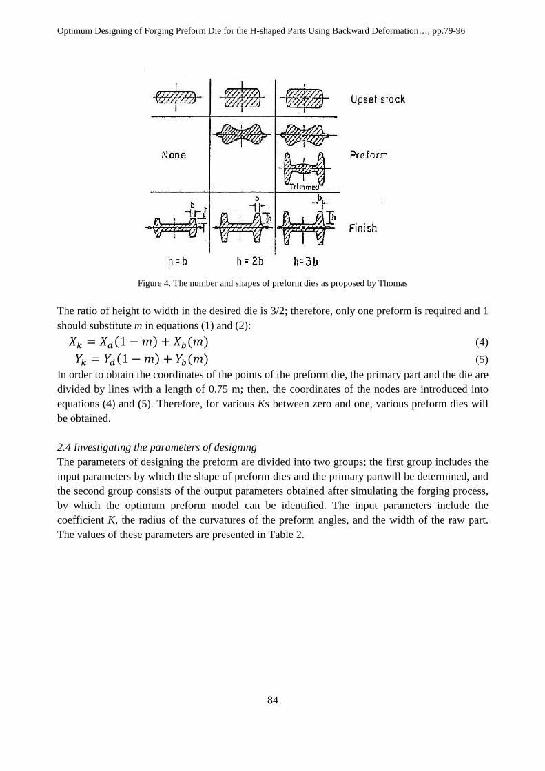
2.3 Designing preform die In order to use equations (1) and (2) to obtain preform dies, the number of preform dies should be given in advance. Therefore, Thomas technique is used to obtain the number of preform dies for H-shaped sections. Thomas divided H-sections into three groups according to the ratio of the height of the wall to its width as presented in Figure 4.
Optimum Designing of Forging Preform Die for the H-shaped Parts Using Backward Deformation…, pp.79-96
84
Figure 4. The number and shapes of preform dies as proposed by Thomas
The ratio of height to width in the desired die is 3/2; therefore, only one preform is required and 1 should substitute m in equations (1) and (2):
�� � �� 1 � �� �� �� (4)
�� � �� 1 � �� �� �� (5) In order to obtain the coordinates of the points of the preform die, the primary part and the die are divided by lines with a length of 0.75 m; then, the coordinates of the nodes are introduced into equations (4) and (5). Therefore, for various Ks between zero and one, various preform dies will be obtained. 2.4 Investigating the parameters of designing The parameters of designing the preform are divided into two groups; the first group includes the input parameters by which the shape of preform dies and the primary partwill be determined, and the second group consists of the output parameters obtained after simulating the forging process, by which the optimum preform model can be identified. The input parameters include the coefficient K, the radius of the curvatures of the preform angles, and the width of the raw part. The values of these parameters are presented in Table 2.
Journal of Modern Processes in Manufacturing and Production, Vol.3, No.3, Summer 2014
85
Table 2. The values of the input parameters
Width of the raw part
The radius of the curvatures of the left and right angles of preform
K coefficient
0.1 0.2 0.3 0.4 0.5 0.6 0.7 0.8 0.9 1
100,100 120,80 140,60 160,40 180,20
300 301
301.5 302
302.5 303
303.5 304
304.5 305
From the whole possible forms from Table 2 containing (10 * 5 * 10) = 500 samples, 75 samples were randomly selected by Matlab Software for analysis. In each of these 75 forms, the geometric shape of the preform is varied according to the K coefficient and the curvatures of the angles; besides, the dimensions of the raw part are also varied. Then the forging process is simulated for these 75 models, and the output parameters including the percentage of filling the die, the most plastic strain of the raw part, and the highest required force are obtained for each model. 2.5 Simulation of Forging In this study, ABAQUS Software 6.10 was used for simulating the process of forging. On this software, the preform and final dies were modeled as rigid axisymmetric, and the raw part was modeled as a formable axis. The analysis was dynamic and explicit having the geometric non-linear condition and the model of the raw part was absolutely plastic without any work hardening in isothermal conditions. In order to mesh the part, axisymmetric rectangle elements of reduced integrating type with four nodes were used (CAX4R). Coulomb friction model with friction coefficient of 0.3 was used in simulations. This value was obtained for Al2014 at 400 C based on the Ring Test. In cases which undergo a lot of deformation during the process, the elements also deform significantly. The complexity and distortion of the elements may lead to stop solving the problems; therefore, re-meshing is required for more accurate analysis. Problems can be analyzed faster and more accurate using the ALE comparative meshing method. While using this method, the elements can move independent of the material; therefore, the quality of the elements remains optimum during the process. In this method, only the situations of the nodes vary and the topology of the elements remains unchanged. As mentioned before, there are 500 possible modes. If we want to obtain the output for all the inputs, the simulation will be very time consuming; therefore, the need is felt for a method to appropriately predict the answers. There are various ways to predict the process; however, since the process contains various and numerous output and input parameters, the intelligent technique of artificial neural network is used. In this method, the outputs for several random inputs are first

Optimum Designing of Forging Preform Die for the H-shaped Parts Using Backward Deformation…, pp.79-96
86
given to the network, which is called training the network. Thereafter, the network predicts the outputs for new inputs by itself. As mentioned before, since the number of the input and output parameters are high and they have different structures, 75 models are used to train the network. This number was obtained by trial and error. By simulating the process of forging, output parameters are obtained for these 75 models, and the neural network is trained. 2.6 Artificial neural network An artificial neural network consists of a set of computational elements called neurons, which function as biological neurons. This network can discover the innate relationships between the data without any pre-knowledge. Therefore, neural networks are used to implement complex functions in various fields including pattern recognition, identification, categorization, speech and image processing, and control systems. Nowadays, neural networks are used to solve difficult problems which cannot be solved by human or simple computers. The most important issue in using this method is designing optimal network according to the type of input parameters. Various factors are effective in designing a network, including the type of the network, network training algorithm, the function of error, the number of layers, and the number of neurons in each layer. 2.6.1 Type of the network With regard to previous studies on neural networks, feed forward network was selected for forging. In this type of networks, the neurons are connected with each other in a way that the neurons in medium layers receive their input from all the neurons in the lower layers –usually the layer of input neurons. Therefore, in a feed forward neural network, signals move from one layer to the upper one until they reach the final layer which is the output of the neural network. Figure 5 illustrates a two-layered feed forward network.
Figure 5. A two-layered feed forward network
2.6.2 Training algorithm In order to train the network, the algorithm was used after propagation, which is a systematic technique to train multi-layered neural networks and is used in most networks. In case of feed forward networks with back-propagation, Batch Training Method is usually used due to the diversity of its training algorithms and faster convergence. There are various methods for batch training of neural networks, one of the most common of which is Levenberg-Marquardt

Journal of Modern Processes in Manufacturing and Production, Vol.3, No.3, Summer 2014
87
Algorithm. In this algorithm, the error function is approximated as a second-degree multi-statement using Taylor’s Expansion, and then the minimum function is found. In fact, this is a variation of Newton’s Classic Algorithm which is used for finding solution for problems which need minimizing. This algorithm is applied in designing networks, using train function. 2.6.3 Network error function According to previous studies on artificial neural networks, the most common and the best error function is the MSE function. On the other hand, this function is a criterion to measure the training and performance of the network. Performance and training mean how well the network can present logical and acceptable responses to the inputs by which it was trained and to new inputs. MSE is the square of the errors between the real and desired outputs of the output layer. In back-propagation, this value is used as the target function, and network weights are considered as the function variable. 2.6.4 Excitation functions With regard to previous studies and the applied method, the only necessity for excitation functions is to be derivative everywhere. Figure 6 illustrates the common excitation functions in designing neural networks.
Figure 6. Common excitation functions in neural networks
With regard to the inputs and the expected outputs and the chosen network in this study, in designing the desired network, Hyperbolic Tangentexcitation function was used in hidden layers, and linear excitation function was used in the last layer. 3. Results 3.1 The number of layers and the number of neurons in each layer The number of hidden layers and the number of neurons in each layer are among the factors determined by the user while modeling. However, no specific method has yet been proposed to determine the appropriate number of hidden layers and neurons; hence, these numbers are determined by trial and error. Therefore, in a modeling process, various structures of neural network are assessed by varying the number of hidden layers and neurons. Optimal neural network is also selected based on this method regarding certain parameters including network error, implementation time, and the correlation between the inputs and the outputs.
Optimum Designing of Forging Preform Die for the H-shaped Parts Using Backward Deformation…, pp.79-96
88
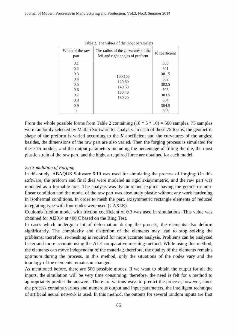
Characteristics of the designed neural networks for each output parameter are presented in Table 3.
Table 3. Characteristics of designed networks
Output parameter Filling percentage for
final die Maximum plastic
strain Maximum
required force
Network type Feed forward Feed forward Feed forward No. layers 3 3 3
Network structure 1,8,5 1,20,15 1,18,12
Training algorithm
trainlm trainlm trainlm
Excitation function
tansig-purelin tansig-purelin tansig-purelin
Error function MSE MSE MSE MSE 0.0000000021 0.0000546 0.00000047
Correlation coefficient
0.923 0.945 0.989
Minimum error -0.11 -0.1 -0.06 Maximum error 0.15 0.02 0.02
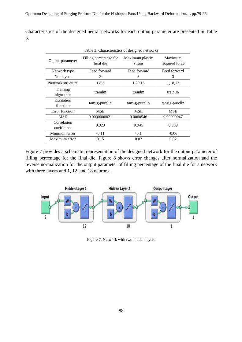
Figure 7 provides a schematic representation of the designed network for the output parameter of filling percentage for the final die. Figure 8 shows error changes after normalization and the reverse normalization for the output parameter of filling percentage of the final die for a network with three layers and 1, 12, and 18 neurons.
Figure 7. Network with two hidden layers

Journal of Modern Processes in Manufacturing and Production, Vol.3, No.3, Summer 2014
89
Figure 8. Error distribution for filling percentage of the final die in networks 1, 12, and 18
For every neuron in the output layer, the coefficient of correlation between the real and desired outputs obtained during a cycle is calculated from the following equation:
(6) where
r is the correlation between real and desired outputs Q is the number of training pairs in information class O is the number of real output from the neural cell
o� is the average number of real outputs from the neural cell d is the number of desired output from the neural cell
d� is the average number of desired outputs from the neural cell
Figures 9 and 10 show the correlation diagrams for the filling percentage of the final die and in normalized mode, respectively. It is notable that as the coefficient of correlation is closer to one, the designed network is more accurate. As can be seen in the figures, this coefficient is very close to one, which shows that the number of layers and neurons and the training algorithm are very well selected and the network is trained appropriately.

Optimum Designing of Forging Preform Die for the H-shaped Parts Using Backward Deformation…, pp.79-96
90
Figure 9. Correlation coefficient in training stage
Figure 10. Correlation in test stage
3.2 Selecting optimal model There are various methods for selecting optimal model using output parameters. In this research, the models were firstly numbered 1 to 500. Then, all the models were graded per various parameters and a coefficient of influence was considered for each parameter. Thereafter, the total points of every model ware calculated, and the optimal model was selected based on these points; consequently, the preform die of the model was selected as the optimal preform. The manner for grading the models is as follows: The filling of the final die should necessarily be between 99.90 to 100 % because in these states the final die is completely filled. It should be mentioned that the models with filling percentages below 99.90 were not acceptable and were ignored.

Journal of Modern Processes in Manufacturing and Production, Vol.3, No.3, Summer 2014
91
The coefficient for the highest plastic strain is 2. Since plastic strain is a negative factor, the model with the highest strain was given 1 and the one with the lowest strain was given 500 points. Then, these points were multiplied by 2. The coefficient of the highest force is 3. Since this is a negative factor, the highest force was given 1 and the lowest force was given 500 points. Then these points were multiplied by 3. The coefficient of the width of the raw part is 5. Since the length and the height of the part are constant, by increasing its width, the load of the fillet is also increased. One of the most effective parameters in forging is the load of the fillet; therefore, the coefficient of 5 is considered for this parameter. This parameter is also a negative factor; therefore, the highest width received 1 and the lowest received 500 points. Then these points were multiplied by 5. Table 4 presents the characteristics of 10 models with the highest points. These models indicate the first 10 preferences for the preform die and the fillet for forging and the desired final die. Accordingly, the first model is selected as the optimal model. Figures 11 and 12 show the counter of plastic strain and the filling percentage of the final die in axisymmetric mode for forging without preform die and forging with optimal preform die, respectively.
Table 4. Proposed preferences for preform and the fillet

Optimum Designing of Forging Preform Die for the H-shaped Parts Using Backward Deformation…, pp.79-96
92
Figure 11. Plastic strain counter and filling percentage of the final die for forging without preform die
Figure 12. Plastic strain counter and filling percentage of the final die for forging with optimal preform
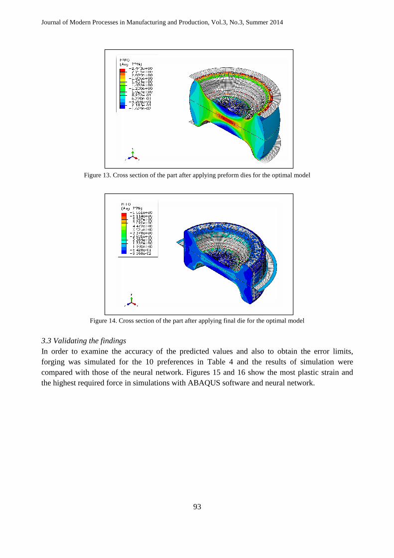
Figures 13 and 14 show the cross section of the part for the first preference (optimal model) by the end of preform stage and by the end of final die stage, respectively.
Journal of Modern Processes in Manufacturing and Production
Figure 13. Cross section of the part after applying preform dies for the optimal model
Figure 14. Cross section of the part after applying final die for the optimal model
3.3 Validating the findings In order to examine the accuracy of the predicted values and also to obtain the error limits, forging was simulated for the compared with those of the neural network. the highest required force in simulations with ABAQUS software and neural network.
Journal of Modern Processes in Manufacturing and Production, Vol.3, No.3, Summer 2014
93
Cross section of the part after applying preform dies for the optimal model
Cross section of the part after applying final die for the optimal model
In order to examine the accuracy of the predicted values and also to obtain the error limits, forging was simulated for the 10 preferences in Table 4 and the results of simulation were compared with those of the neural network. Figures 15 and 16 show the most plastic strain and the highest required force in simulations with ABAQUS software and neural network.
Cross section of the part after applying preform dies for the optimal model
Cross section of the part after applying final die for the optimal model
In order to examine the accuracy of the predicted values and also to obtain the error limits, and the results of simulation were
how the most plastic strain and the highest required force in simulations with ABAQUS software and neural network.

Optimum Designing of Forging Preform Die for the H-shaped Parts Using Backward Deformation…, pp.79-96
94
Figure 15. Maximum plastic strain obtained in two ways
Figure 16. Maximum required force obtained in two ways
As can be observed, the designed neural network has a better accuracy in obtaining the maximum plastic strain while in predicting the maximum required force, it is vice versa. The average error of prediction by the neural network and limited component solution is 2% for maximum plastic strain and 8% for maximum required force. The reason for higher error of the neural network in predicting the maximum force is the sudden changes in this parameter. However, the accuracy of both methods is acceptable, and the results are valid.

Journal of Modern Processes in Manufacturing and Production, Vol.3, No.3, Summer 2014
95
4. Discussion The study discussed various parameters, and the neural network technique was used to predict the forging process. Neural networks are superior to other common systems; however, they are concerned with certain imperfections, the most significant of which are mentioned below:
1. There are no specific rules or principles to design the network for an optional application. 2. In case of modeling problems, one cannot understand the physics of the issue solely by
using neural network. In other words, it is usually impossible to relate the parameters of the network to those of the process.
3. The accuracy of the findings is significantly dependent on the size of the training set. 4. Training the network can be difficult or even impossible. 5. Predicting the future performance of the network and generalizing its performance are not
simple tasks.
5. Conclusion The present study was aimed to offer a comprehensive method to design preform dies based on backward deformation and limited element and also to obtain the preforms for a given die. From among the obtained preforms, 75 models were randomly selected to train the network, and forging was simulated for these 75 models on ABAQUS software. Afterwards, the best neural networks were designed for the output parameters and were trained using the data on the 75 models. Then, the models were ranked using weight coefficients, and the first 10 preferences were selected. In order to examine the accuracy of the network, forging was simulated for these 10 models using ABAQUS software. Comparison of the results of simulation with those of the neural network confirmed the accuracy of the designed neural network. The major achievements of the present study can be summarized as follows:
1. Presenting a comprehensive method for the design of the perform die in forging based on backward deformation and limited element;
2. Examining the parameters of filling percentage of the final die, maximum plastic strain, and maximum required die per perform die deformation and the size of the part;
3. Simulating the multi-step forging process using ABAQUS software; 4. Investigating various types of neural network to design the best network with minimum
error and the highest correlation; 5. Identifying the best network for predicting the parameters of filling percentage of the final
die, maximum plastic strain, and maximum required force; 6. Ranking the perform dies and various sizes of the part to optimize forging process.
6. References [1] Altan, T., Boulger, F.W. and Becker, J.R. 1973. Forging Equipment, Materials, and Practices,
Battelle Columbus Laboratories, Metalworking Division. [2] Brukhanov, A. and Rebelsky, A. 1962. Hot Closed Die Forging- Designing and Calculation of
Dies, Gntiml, Moscow. [3] Chamouard, A. 1964, Eslampage et forge, Dound, Paris. [4] Thomas, G. B., 1980. Forging Handbook, vol. 2, Die Design, DFRA Manual.

Optimum Designing of Forging Preform Die for the H-shaped Parts Using Backward Deformation…, pp.79-96
96
[5] Hwang, T.S.M. and Kobayashi, S. 1984. Perform design in plain strain rolling by the finite element method, International Journal of Machine Tool Design Research, 24(4), 253-266.
[6] Biglari, F.R., Abrinia, K., Chasemi, H., Nikbin, K.M. and O’Dowd, N.P. 2003. Near net shape forging using backward deformation method, Conference on Computational Plasticity, COMPLAS.
[7] Qingbin, L., Wu, S. and Sun, S. 1998. Preform design in axisymmetric forging by a new FEM–UBET method, Journal of Materials Processing Technology, 74, 218-222.
[8] Tomov, B. and Radev, R. 2004. An example of determination of preforming steps in hot die forging. Journal of Materials Processing Technology, 157(158), 617-619.
[9] Kim, D.J. and Kim, B.M., 2000. Application of neural network and FEM for metal forming processes, International Journal of Machine Tools and Manufacture, 40, 911-925.
[10] Sedighi, M., Hadi, M. and Kolahdouz, S. 2009. Optimization of Preform in Close Die Forging by Combination of Neural Network and Genetic Algorithm, World Applied Sciences Journal, 7(14), 1464-1473.
[11] Lee, S. R., Lee, Y.K., Park, C.H. and Yang, D.Y. 2002. A new method of preform design in hot forging by using electric field theory, International Journal of Mechanical Sciences, 44, 773-792.
[12] Castro, C.F., Antonio, C.A.C. and Sousa, L.C. 2004. Optimization of shape and process parameters in metal forging using genetic algorithms, Journal of Materials Processing Technology, 146, 356-364.
[13] Ko, D.C., Kim, D.H. and Kim, B.M. 1999. Application of artificial neural network and Taguchi method to preform design in metal forming considering workability. International Journal of Machine Tools & Manufacture, 39, 771-785.
[14] Tang, Y.C., Zhou, X.H. and Chen, j. 2008. Preform tool shape optimization and redesign based on neural network response surface methodology. Finite Elements in Analysis and Design, 44, 462-471.
[15] Altan, T., Oh, S.I. and Gegel, H.L. 1983. Metal Forming: Fundamentals and Applications, American Society for Metals, Metals Park.
[16] Hagan, M., Demuth, H. and Beale, M.H. 1996. Neural Network Design, PWS Publishing Company, Boston.