optimizations of dynamic
TRANSCRIPT


OPTIMIZATIONS OF DYNAMIC
VIBRATION ABSORBERS FOR
SUPPRESSING VIBRATIONS IN
STRUCTURES
CHEUNG YAN LUNG
A thesis submitted in partial fulfillment of the requirements for
the Degree of Doctor of Philosophy
April 2009
THE HONG KONG POLYTECHNIC UNIVERSITY
Department of Mechanical Engineering

Abstract
i
ABSTRACT
H∞ and H2 optimization of the traditional dynamic vibration absorber (DVA) in single
degree-of-freedom (SDOF) system are classical optimization problems and have been
already solved for a long time. However, the H∞ and H2 optimization of the dynamic
vibration absorbers in multi-degree-of-freedom (MDOF) or continuous systems have
not been solved. Some researchers found out the optimum tuning conditions of
MDOF or continuous systems but all the methods found in the literature are numerical
optimizations and the results cannot provide physics insight on the effect of each
tuning parameter to the performance of vibration suppression of the primary vibrating
system. Optimization theories of the traditional DVA for suppressing vibration in
beam and plate structures have been established and reported in this thesis, and better
tuning conditions of the DVA have been found in comparison to those reported by
other researchers.
Non-traditional designs of the DVA are some recent research topics. One of these
designs has been proved to perform better than the traditional design in some
applications and it is studied and reported in this thesis. Researchers in this area tend
to use the fixed-points theory of Den Hartog (1985) in searching the optimum tuning
conditions of DVAs. However, it has been shown in this thesis that the fixed-points
theory may not applicable in some tuning conditions of a non-traditional DVA. A
new theory is established for finding the optimum tuning condition of the
non-traditional DVA.
Publications arising from the thesis
ii
PUBLICATIONS ARISING FROM THE THESIS
International Journals
1. Wong W.O., Tang S.L., Cheung Y.L., Cheng L., Design of a dynamic vibration
absorber for vibration isolation of beams under point or distributed loading,
Journal of Sound and Vibration, Volume 301, Issues 3-5, 3 April 2007, Pages
898-908;
2. Wong W.O., Cheung Y.L., Optimal design of a damped dynamic vibration
absorber for vibration control of structure excited by ground motion, Engineering
Structures, Volume 30, Issue 1, January 2008, Pages 282-286;
3. Cheung Y.L., Wong W.O., H∞ and H2 optimizations of a dynamic vibration
absorber for suppressing vibrations in plates, Journal of Sound and
Vibration, Volume 320, 2009, Pages 29-42.
4. Cheung Y.L. and Wong W.O. Design of a non-traditional dynamic vibration
absorber, The Journal of the Acoustical Society of America, 126 (2), August 2009,
Pages 564-567.
Conference Paper
1. Cheung Y.L., Wong W.O., Optimization of Dynamic Vibration Absorbers for
Vibration Suppression in Plates, IMAC-XXVI: Conference & Exposition on
Structural Dynamic.

Acknowledgements
iii
ACKNOWLEDGEMENTS
It is a pleasure to express my gratitude to many who have helped in this research
project. I would like to thank Dr W.O. Wong, for his guidance, comment and
constructive criticism throughout my research study. My grateful acknowledgements
also go to Mr. K.H. Hui and Mr. Raymond H.T. Lam, for their technical support
The financial support from the Hong Kong Polytechnic University is much
appreciated.
Finally, I wish to thank anyone for support and encouragement in the last four years.

Contents
iv
CONTENTS
ABSTRACT .................................................................................................................... i
PUBLICATIONS ARISING FROM THE THESIS....................................................... ii
ACKNOWLEDGEMENTS ......................................................................................... iii
CONTENTS .................................................................................................................. iv
LIST OF FIGURES ...................................................................................................... vi
NOTATIONS AND ABBREVIATIONS ....................................................................... x
1. INTRODUCTION ..................................................................................................... 1
1.1 Literature review .............................................................................................. 1
1.2 Motivation of the present study ....................................................................... 5
1.3 Thesis contents and new results ....................................................................... 7
2. DVA FUNDAMENTALS .......................................................................................... 9
2.1 Vibration of a SDOF system excited by an external force ............................... 9
2.2 The vibration in a SDOF system with a DVA excited by an external force .. 12
2.3 Vibration of a SDOF system excited by support motions .............................. 14
2.4 Vibration of a SDOF system with a DVA under ground motions .................. 16
2.5 Summary ........................................................................................................ 18
3. OPTIMIZATIONS OF THE TRADITIONAL DVA FOR SUPPRESSION
VIBRATIONS IN SDOF SYSTEM ............................................................................ 19
3.1 H∞ optimization of the traditional DVA for SDOF system ............................ 19
3.2 H2 optimization of the traditional DVA for SDOF system ............................ 29
3.3 Summary ........................................................................................................ 33
4. OPTIMIZATIONS OF THE TRADITIONAL DVA FOR SUPPRESSION
VIBRATIONS IN BEAM STRUCTURES ................................................................. 35
4.1 The frequency response function of the beam structure with the traditional
DVA ..................................................................................................................... 37
4.2 Optimization for minimizing the vibration at a point on the beam structure. 41
4.3 Optimization for minimizing the root mean square motion over the whole
domain of the beam structure ............................................................................... 45
4.4 Numerical Simulation .................................................................................... 50
4.5 Effect of the tuned DVA in other modes ........................................................ 57
4.6 Conclusion in the optimization of DVA for suppressing vibrations in beam
structures .............................................................................................................. 62
5. OPTIMZATIONS OF THE TRADITIONAL DVA FOR SUPPRESSING
VIBRATIONS IN PLATE STRUCTURES ................................................................. 63
5.1 Theory ............................................................................................................ 64
5.2 Optimization for minimizing the vibration at a point (x,y) on the plate ........ 70

Contents
v
5.3 Optimization for minimizing the root mean square motion over the whole
domain of the plate............................................................................................... 74
5.4 Simulation results and discussion .................................................................. 79
5.5 Summary ........................................................................................................ 83
6. OPTIMIZATION OF A NON-TRADITIONAL DYNAMIC VIBRATION
ABSORBER ................................................................................................................ 85
6.1 H∞ optimization of the non-traditional DVA ................................................. 86
6.1.1 Local optimization of the non-traditional DVA using the fixed-points
theory ........................................................................................................... 93
6.1.2 Global optimization of the non-traditional DVA ................................ 99
6.2 H2 optimization of the non-traditional DVA ................................................ 103
6.3 Summary ...................................................................................................... 108
7. CONCLUSIONS.................................................................................................... 109
APPENDIX A. EULER-BERNILLI BEAM WITH A FORCE ................................ 111
APPENDIX B. THE FORCE DUE TO DVA APPLIED ON THE BEAM ............... 113
REFERENCES .......................................................................................................... 114
List of figures
vi
LIST OF FIGURES
Page
Figure 2.1 A SDOF vibrating system under an external force. 9
Figure 2.2 Frequency response function of a SDOF system under an
external harmonic force.
11
Figure 2.3 Primary system with DVA under an external force. 12
Figure 2.4 Frequency response function of a SDOF system with a DVA
excited by an external force. 13
Figure 2.5 A SDOF system excited by support motion. 14
Figure 2.6 Frequency response function of a SDOF system excited by
support motions.
15
Figure 2.7 Primary system with DVA under a ground excitation 16
Figure 3.1 The frequency response of the primary system with DVA at
1=γ
21
Figure 3.2 The height of fixed points in the frequency response spectrum
of mass M versus tuning ratio γ at 2.0=µ 23
Figure 3.3 ( ) ( )( )ba HH λλζγ
,max,
versus tuning ratio γ at 2.0=µ 23
Figure 3.4 The frequency response of the primary mass M with DVA
tuned at ∞Hγ
24
Figure 3.5 The frequency response of the primary system with DVA using
the H∞ optimum tuning 27
Figure 3.6 Mass ratio vs. tuning ratio in different optimization methods 33
Figure 3.7 Mass ratio vs. damping ratio in different optimization methods 34
Figure 4.1 The cantilever beam with a DVA under a external force 37
Figure 4.2 The simply supported beam with DVA under a concentrated
force
50

List of figures
vii
Figure 4.3 Frequency responses of the beam at x = x0 with very light damping
and optimum tuning frequency and damping in the DVA
51
Figure 4.4 Frequency responses of the beam at x = x0 with the proposed
optimum parameters of the DVA and the ones made by Den
Hartog.
52
Figure 4.5 Schematics of a simply supported beam with a vibration
absorber excited by a random force at x= 0.1L.
53
Figure 4.6 Kinetic energy (in J/N2) of a simply supported with optimum
vibration absorber fitted at xo = 0.5L with the first natural
frequency as the control target: (a) figure showing all three
modes; (b) in the vicinity of the first mode. --------- T =
0.8333, ζ = 0.25 (Dayou 2006), ———— T = 0.8775, ζ =
0.2556 (present theory)
56
Figure 4.7 The cantilever beam with an equivalent spring and an
equivalent damper under a external force
58
Figure 4.8 The equivalent stiffness and the equivalent damping
coefficient of the DVA
59
Figure 4.9 The primary system with the equivalent spring and damper 60
Figure 5.1 A simply-supported rectangular plate under external
distributed force w(t)g(x,y)
64
Figure 5.2 Dimensionless motion power spectral density of a square
plate with g(x,y) =1, µ = 0.275, xo = yo = a/2. -------
Jacquot’s result (2001); ——— Present theory, Equation
(26); —‧—‧—‧— No absorber added.
80
Figure 5.3 Contour plot of the mean square motion of the plate at the
attachment point of DVA at different tuning and damping
ratios
81
Figure 6.1 A SDOF system (M-K) mounted with the new DVA (m-k-c)
excited by an external force
87

List of figures
viii
Figure 6.2 The frequency response of the primary system with the new
DVA at 1=γ
88
Figure 6.3 Response at the (height of) fixed points versus tuning ratio
at 2.0=µ
90
Figure 6.4 ( ) ( ) ( )( )0,
,,max λλλζγ
HHH ba versus tuning ratio at 2.0=µ 91
Figure 6.5 The frequency response of the primary system with a new
DVA at localopt _γ .
94
Figure 6.6 Frequency response of the primary mass M with the new DVA
using the local optimum tuning
97
Figure 6.7 Frequency response of the primary mass M with the traditional
DVA using the optimum tuning and with the new DVA using
the local optimum tuning
98
Figure 6.8 Mass ratio versus the height of the fixed point using different
type of DVA.
98
Figure 6.9 The frequency response of the primary system with the new
DVA using optimum damping ratio globalopt _ζ , µ = 0.2 and
tuning ratio γ = 2.
102
Figure 6.10 The frequency response of the primary system with the new
DVA using optimum damping ratio globalopt _ζ , µ = 0.2 and
tuning ratio γ = 3.
102
Figure 6.11 The contour plot of the mean square motion at 11.0=µ . (*) –
local minimum; (∆) – local maximum
105
Figure 6.12 The contour plot of the mean square motion at 2.0=µ 106
Figure 6.13 The contour plot of the mean square motion at 11.0=µ . (*) – 107

List of figures
ix
local minimum; (∆) – local maximum; (-) – optimum damping
Figure A.1 Figure A.1 Free body diagram of the beam element 111
Figure A.2 Figure A.2 Force due to DVA acting on the primary mass M 113

Notations and abbreviations
x
NOTATIONS AND ABBREVIATIONS
A Cross section area of the beam
c Damping coefficient of the dynamic vibration absorber
C Damping coefficient of the primary system
E Young modulus of the structure
f The external force
F The amplitude of the external force
h The thickness of the plate
( )⋅H The frequency response function
I The second moment of area
j 1−
k Elastic stiffness of the dynamic vibration absorber
K Elastic stiffness of the primary system
L The length of the beam
Lx The length of the plate
Ly The length of the plate
m Mass of the dynamic vibration absorber
M Mass of the primary system
ε ( )0
2 xnµϕ (Chapter 4) and ( )00
2 , yxαβµϕ (Chapter 5)
( )⋅δ Delta function
φ The phase of the primary system
)(⋅iϕ ith
mode function of the structure
γ The tuning ratio between the primary system and the DVA, i.e.
n
a
ωω

Notations and abbreviations
xi
λ The frequency ratio nω
ω
µ The mass ratio between the primary system and the DVA,
Mm
ν The Poisson ratio
ρ The density of the structure
ω The exciting frequency of the external source
aω The natural frequency of the DVA, m
k
nω The natural frequency of the primary system, M
K
ζ The damping factor of the primary system, MK
C2
aζ The damping factor of the DVA, mk
c2
DVA Dynamic vibration absorber
SDOF Single-degree of freedom
MDOF Multi-degree of freedom

1. Introduction
1
1. INTRODUCTION
1.1 Literature review
The traditional dynamic vibration absorber (DVA) is an auxiliary mass-spring
system which, when correctly tuned and attached to a vibrating system subject to
harmonic excitation, causes to cease the steady-state motion at the point to
which it is attached (e.g. Korenev and Reznikov 1993, Den Hartog 1985, Hunt
1979). It has the advantage of providing a cheap and easy-to-maintain solution
for suppressing vibration in vibrating systems with harmonic excitation. The first
research conduced at the beginning of the twentieth century considered an
undamped DVA tuned to the frequency of the disturbing force by Frahm (1911).
Such an absorber is a narrow-band type as it is unable to eliminate structural
vibration after a change in the disturbing frequency. Application of damping
substantially widened the frequency band of the DVA’s efficient operation.
Finding the optimum parameters of a viscous friction DVA in SDOF system
drew the attention of many scholars. One of the optimization methods is H∞
optimization. Ormondroyd and Den Hartog (1928) proposed the optimization
principle of the damped DVA in terms of minimizing the maximum amplitude
response of the primary system, which called H∞ optimization of dynamic
vibration absorber. Following this principle, Hahnkamm (1932) deduced the
relationship for the optimum tuning of DVA using in the SDOF system. Brock
(1946) developed the approximated optimum damping. This optimum design
method of the dynamic vibration absorber is called the “fixed-points theory”,
which was well documented in the textbook by Den Hartog (1985). The exact
1. Introduction
2
solution of the H∞ optimization for the DVA attached to undamped primary
system was derived by Nishihara and Asami (1997). And the other important
optimization method is H2 optimization. Crandall and Mark (1963) proposed
another optimization principle of the damped DVA in terms of minimizing the
total vibration energy of the primary structure under white noise excitation,
which called H2 optimization of dynamic vibration absorber. The exact solution
of the H2 optimization for the DVA attached to undamped primary system was
derived by Warburton (1980, 1981, 1982). Asami and Nishihara (2002) proposed
the exact solution of the H2 optimization for the DVA attached to damped
primary system.
However, when applying dynamic vibration absorber to a continuous structure
such as a beam, vibration can be eliminated only at the attachment point of the
vibrating beam while amplification of vibration may occur in other parts of the
beam. Research results on suppressing vibration in a region or the whole span
of a beam structure by using the dynamic vibration absorber have been reported
recently.
Many investigators discussed the optimum parameters of a viscous friction DVA
in MDOF system. Rice (1993) reported the use of SIMPLEX nonlinear
optimization method to determine the H∞ optimum tuning of a DVA applied for
suppressing the vibration of beam. Hadi and Arfiadi (1998) used a genetic
algorithm to solve numerically the H2 optimum tuning for a MDOF system.
Jacquot (1976, 2000, 2001, 2003, 2004) provided the method to handle the
problem when the system is with an additional sub-system and determined the
H2 optimum damping based on the transfer functions of a beam and a plate.

1. Introduction
3
Brennan and Dayou (2000), Dayou and Kim (2005), and Dayou (2006) applied
the fix-points theory and proposed a set of optimum tuning for global control of
the kinetic energy of a continuous structure using DVA. Cha (2001, 2002, 2004,
2005, 2007), Cha and Ren (2006), and Cha and Zhou (2006) used multiple
absorbers to isolate the vibration in a region of a vibrating structure.
Some investigators discussed the non-traditional DVAs. Ren (2001) and Liu and
Liu (2005) proposed a new design of the DVA, which they connected the damper
of the DVA to the ground rather than the primary structure, and derived the new
optimum tuning which is better than the traditional one. Tang (2005) designed a
rotational dynamic absorber (RVA) for absorber for absorbing rotational motion
of a vibration structure. His simulation result showed that the vibration of the
structure can be isolated in the forced region of a beam structure if both a
translational DVA and a RVA are attached at a proper location on the beam.
Recent advances of the absorber designs with active controlled elements (Takita
and Seto 1989, Moyka 1996, Tentor 2001, Jalili and Knowles, 2004, Chen, Fuh
and Tung, 2005, Lin, 2005, Wu et al. 2007a, 2007b, 2007c) may be more flexible
and powerful than the traditional spring mass absorber. One of the concepts of
the absorber with active controlled elements is called Semi-Active dynamic
vibration absorber. Semi-active DVAs allow the system parameters to be varied
after implementation. The semi-active DVA may have variable inertia, variable
damping, variable stiffness or variable initial conditions. A major advantage of
semi-active system is the small energy expenditure needed to reduce vibration.
Another important advance of the absorber is called active or hybrid dynamic
vibration absorber. Active or hybrid DVAs have an arbitrary force actuator and

1. Introduction
4
controller in parallel with the spring and damper. This adds flexibility to
incorporate control theory to provide counteracting force to the primary structure.
This force has frequently been implemented with a voice coil actuator design.
The majority of literature on this topic focuses on control methodology. However,
these advanced absorbers require special knowledge in the design and operation,
and their applications may be justified when more sophisticated vibration control
solutions are required. On the other hand, the passive dynamic vibration
absorber provides a cheaper and convenient solution for vibration suppression
and isolation of vibrating systems with harmonic excitation.
The application of the DVA is also a research area for the researchers. One
important application is the structural-borne noise attenuation using dynamic
vibration absorbers. Fuller (1982, 1984) presented a technique for tuning
absorbers applied to cylindrical shell to minimize radiated sound. Nagaya and Li
(1997) presented a method using neural network procedure in solving non-linear
equations in predicting tuning parameters of the absorber for higher mode noise
absorber. Since absorbers can be made small and light and they can be installed
conveniently, it finds widely application of DVA on attenuating the noise.

1. Introduction
5
1.2 Motivation of the present study
The present study is concerned with the optimum tuning of DVA in SDOF,
MDOF and continuous systems for vibration suppression. Research results may
be applied in engineering applications such as bridge, building, naval structures
and pressure vessel.
The optimum tuning conditions of the traditional DVA in SDOF system is well
introduced in literature. However, most of the relevant methods found in
literature about the optimum tunings of the traditional DVA in MDOF system are
numerical ones such as those reported by Rice (1993), Hadi and Arfiadi (1998),
and Jacquot (1976, 2000, 2001, 2003, 2004) etc. These numerical methods can
only provide case by case solution to the problems and the effects of different
parameters of the DVA such as its mass, damping, stiffness and its attachment
point on the primary structure to the vibration suppression performance remain
unclear. It has been shown by Wong et al (2007) that an improper location of the
attachment point of a DVA on a beam can amplify the vibration in some region
of the structure. Dayou (2006) proposed using the fixed-points theory to find
the optimum tuning in MDOF system. However, his optimum tuning is not the
same as those reported by Asami and Nishihara (2003), and Korenev and
Reznikov (1993). In the present studies, the optimum tunings in beam and plate
structures and a structure are presented and some new results are reported.
Another study is on a non-traditional design of DVA proposed by Ren (2001),
and Liu and Liu (2005). They applied the fixed-points theory to find out the
optimum tuning condition of the DVA. However, the fixed-point theory is
suitable for the traditional DVA but it is no always correct for other DVA designs.
1. Introduction
6
In the present studies, it has been the fixed-points theory cannot be used in some
tuning conditions of this non-traditional DVA and a new method is proposed for
finding the optimum tuning condition of this DVA and the performance of
vibration suppression of the optimized DVA is tested.

1. Introduction
7
1.3 Thesis contents and new results
The text is organized into six chapters and an appendix. This chapter has
presented the literature review of the DVA. The second chapter outlines the DVA
fundamentals.
Chapter 3 derives the vibration and optimization theories of using the traditional
DVA for vibration suppression in SDOF system. H∞ optimization and H2
optimization theories have been derived. In H∞ optimization, the fixed-points
theory is introduced and the discussion in the fixed-points theory is presented in
this chapter.
Chapter 4 establishes the optimization theories of the traditional DVA in beam
structures. H∞ optimization and the H2 optimization theories are established for
Euler-Bernoulli beams and an approximated optimum tuning condition of the
DVA for suppressing vibrations in beam structures are presented in this chapter.
Chapter 5 establishes the optimization theories of the traditional DVA in plate
structures. Plate structures can be commonly found in different types of
engineering application. H∞ optimization and the H2 optimization theories are
established for Kirchhoff plates and an approximated optimum tuning condition
of the DVA for suppressing vibrations in plate structures are presented in this
chapter.
Chapter 6 establishes the optimization theories of a non-traditional DVA. H∞
optimization and the H2 optimization theories are established and the optimum
tuning conditions of this DVA for suppressing vibrations in SDOF systems are
presented in this chapter.

1. Introduction
8
Findings from the present research work are summed up in Chapter 7. Future
work is also recommended and proposed, which of importance and needs to be
conducted further.

2. DVA Fundamentals
9
2. DVA FUNDAMENTALS
Vibration theories of a single degree of freedom system (SDOF) with and
without a DVA excited by an external force or ground motions are presented in
this chapter,.
2.1 Vibration of a SDOF system excited by an external force
A SDOF, mass-spring-damper system excited by an external force f is illustrated
in Figure 2.1.
Figure 2.1 A SDOF vibrating system under an external force.
The equation of dynamic motions of mass M can be written as
fKxxCxM =++ &&& (2.1)
The frequency response function of mass M can be written as

2. DVA Fundamentals
10
( )ωω
ωjCMK
K
KF
XH
+−==
2, (2.2)
The amplitude and the phase of the of mass M are
( )( ) ( )222
2
ωωω
CMK
K
KF
XH
+−== , (2.3)
and 2
tanω
ωφ
MK
C
−= (2.4)
where X is the amplitude of oscillation of the primary system, φ is the phase of
the displacement with respect to the exciting force, F is the amplitude of the
excitation, ω is the exciting frequency and 1−=j . Using equations 2.2, 2.3
and 2.4, the frequency response function may be written in dimensionless form
as
( )ζλλ
λj
KF
XH
21
12 +−
== (2.5)
where λ is the frequency ratio or dimensionless frequency nω
ω , ζ is the
damping factor of the primary system, i.e. MK
C2
=ζ and nω is the
natural frequency of the primary system, i.e. M
Kn =ω .
The amplitude and the phase of the primary system are,
( )( ) ( )222
21
1
ζλλλ
+−==
KF
XH (2.6)
and 21
2tan
λζλ
φ−
= (2.7)

2. DVA Fundamentals
11
The frequency response graph is shown in figure 2.2. It is seen that there is one
resonance and the response is highest at the resonant frequency,
21 ζωω −= nd .
Figure 2.2 Frequency response function of a SDOF system under an external
harmonic force.

2. DVA Fundamentals
12
2.2 The vibration in a SDOF system with a DVA excited by an
external force
Figure 2.3 Primary system with DVA under an external force.
One of the reasons in using DVA is to eliminate the vibration of the primary
system in a particular frequency such as the resonant frequency. The primary
system with DVA excited by an external force f is shown in figure 2.3.
Assuming 0=C , the differential equations for the vibrations are
=
−
−++
−
−+
00
0
111
f
x
x
kk
kkK
x
x
cc
cc
x
x
m
M
&
&
&&
&& (2.8)
and the frequency response function can be written as
( ) ( )( )[ ] ( )22222
2
ωωωωωωωω
ωmMKjckmmkMK
jcmk
F
XH
−−+−−−
+−== (2.9)
Equation 2.9 can be rewritten in form of the dimensionless parameters as

2. DVA Fundamentals
13
( ) ( )( )[ ] ( )2222222
22
121
2
µλλγλζγµλλγλγλζλγ
λ−−+−−−
+−==
a
a
j
j
KF
XH (2.10)
where γ is the natural frequency ratio between the primary system and the DVA,
i.e. n
a
ωωγ = , aω is the response frequency of the DVA, i.e.
mk
a =ω ,
aζ is the damping factor of the DVA, i.e. mk
ca
2=ζ and µ is the mass
ratio, i.e. M
m=µ . Let 1=γ and 0=ζ that the DVA can eliminate the
highest response at the resonant frequency. As shown in figure 2.4, the frequency
response of the primary system at the resonant frequency can be reduced to zero.
However, two resonant peaks appeared in the frequency spectrum of the mass M.
Figure 2.4 Frequency response function of a SDOF system with a DVA
excited by an external force.

2. DVA Fundamentals
14
2.3 Vibration of a SDOF system excited by support motions
This is the case that the primary system is excited by support motions as
illustrated in figure 2.5.
Figure 2.5 A SDOF system excited by support motion.
The differential equation for the vibrations of the main mass is
KyyCKxxCxM +=++ &&&& (2.11)
And the frequency response function can be written as
( )ωω
ωω
jCMK
jCK
Y
XH
+−+
==2
(2.12)
The amplitude and the phase of the primary system are,
( ) ( )( ) ( )222
22
ωω
ωω
CMK
CK
Y
XH
+−
+== (2.13)
and ( ) ( )22
3
tanCMKK
MC
ωω
ωφ
+−= (2.14)

2. DVA Fundamentals
15
Y is the amplitude of the excitation. Using the dimensionless parameters into
equations 2.13 and 2.14, the equations become,
( )ζλλ
ζλλ
j
j
Y
XH
21
212 +−+
== (2.15)
( ) ( )( ) ( )222
2
21
21
ζλλ
ζλλ
+−
+==
Y
XH (2.16)
The frequency response graph is shown in figure 2.6. It is the same as the
previous case that there is one resonance and the highest response appears at the
resonant frequency. Magnitude of frequency response with any damping has the
same value of ( ) 1=λH at frequency 2=λ .
Figure 2.6 Frequency response function of a SDOF system excited by support
motions.
2. DVA Fundamentals
16
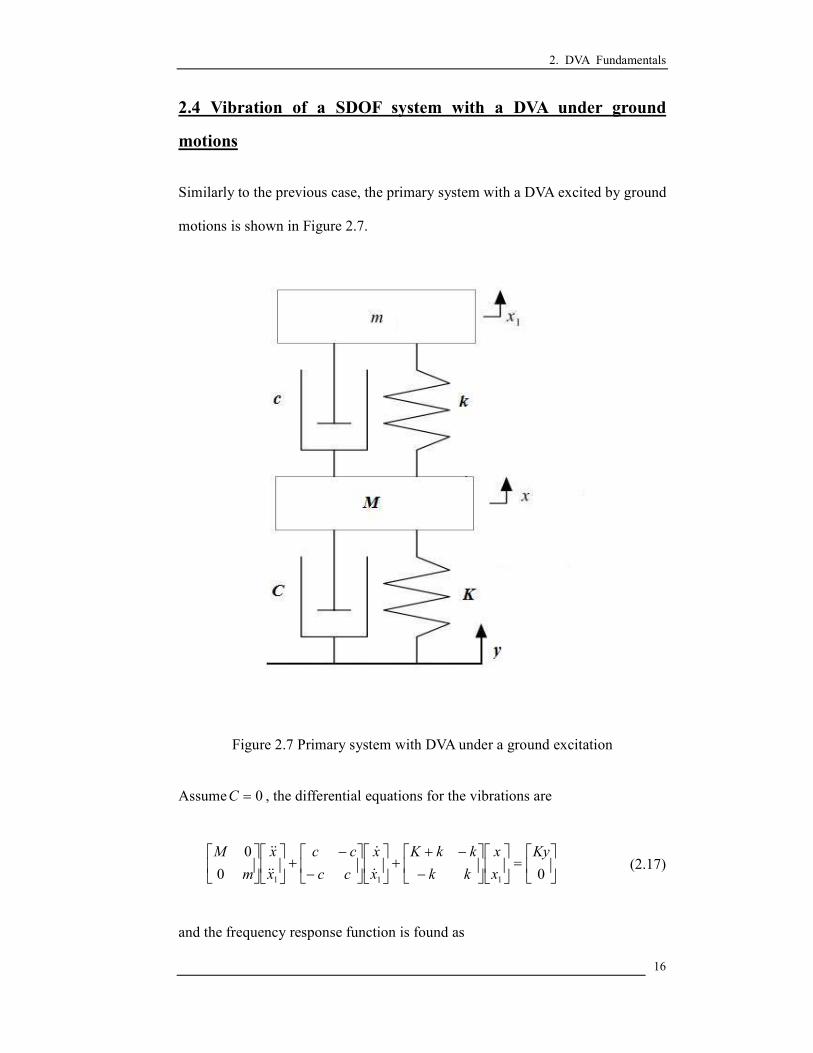
2.4 Vibration of a SDOF system with a DVA under ground
motions
Similarly to the previous case, the primary system with a DVA excited by ground
motions is shown in Figure 2.7.
Figure 2.7 Primary system with DVA under a ground excitation
Assume 0=C , the differential equations for the vibrations are
=
−
−++
−
−+
00
0
111
Ky
x
x
kk
kkK
x
x
cc
cc
x
x
m
M
&
&
&&
&& (2.17)
and the frequency response function is found as

2. DVA Fundamentals
17
( ) ( )( )( )[ ] ( )22222
2
ωωωωωωωω
ωmMKjckmmkMK
jcmkK
Y
XH
−−+−−−
+−== (2.18)
Equation 2.18 can be rewritten using the dimensionless parameters as
( ) ( )( )[ ] ( )2222222
22
121
2
µλλγλζγµλλγλγλζλγ
λ−−+−−−
+−==
a
a
j
j
Y
XH (2.19)
Since equation 2.19 is identical to equation 2.10, the frequency response in this
case is the same as the previous case.

2. DVA Fundamentals
18
2.5 Summary
In this chapter, the vibrations of a SDOF primary system exited by an external
force or ground motions are presented. Different source of the excitation such as
an external force at the primary system or a ground excitation can produce
different frequency responses of the primary system. It means that the strategy of
eliminating the vibration in the primary system should be different for different
kinds of excitation even if the primary system is same.
One of the most common ideas to use the DVA is to set the natural frequency of
the DVA to be the same as that of the primary system, i.e. 1=γ , so that the
vibration at the resonant frequency becomes zero. However, some researchers
such as Den Hartog (1985), Korenev and Reznikov (1993) pointed out the
problems in adopting this idea. One of the problems is that the effective
frequency range is very limited. Two new resonant frequencies appear after the
DVA is attached and these two resonant frequencies are closed to the original
resonant frequency. So the primary system becomes sensitive when the external
force frequency is changed slightly. So, some researchers proposed other ideas to
use the DVA in better ways which will be discussed in the following chapters.

3. Optimizations of the traditional DVA for suppression vibrations in SDOF system
19
3. OPTIMIZATIONS OF THE TRADITIONAL DVA FOR
SUPPRESSION VIBRATIONS IN SDOF SYSTEM
The derivation of the optimization theories of the traditional DVA for suppressing
vibrations in a SDOF system is presented in this chapter. Two different types of
excitations, harmonic excitation with a varying frequency and stationary random
excitation, are considered. Different optimization methods, H∞ optimization and H2
optimization, are introduced for different types of excitation.
3.1 H∞∞∞∞ optimization of the traditional DVA for SDOF system
One of the disadvantages of using the undamped DVA is that the frequency range is
very limited. The vibration of the primary system becomes large when the frequency
of the excitation is changed. So, some researchers proposed other optimization
schemes which can be more effective in using the DVA for vibration absorption.
In the previous chapter, the frequency response functions of the SDOF with a DVA
are discussed. The frequency response functions of the system excited by an external
force or due to ground motions are stated below for the ease of discussions.
( ) ( )( )[ ] ( )2222222
22
121
2
µλλγλζγµλλγλγλζλγ
λ−−+−−−
+−==
a
a
j
j
KF
XH
(2.16)
( ) ( )( )[ ] ( )2222222
22
121
2
µλλγλζγµλλγλγλζλγ
λ−−+−−−
+−==
a
a
j
j
Y
XH (2.19)
Ormondroyd and Den Hartog (1928) pointed out the damping of the DVA has an
optimum value so as to minimize amplitude response of the SDOF system. Such
optimization criterion is now known as H∞ optimization. The objective is to minimize
the maximum amplitude ratio of the response of the primary system to the excitation

3. Optimizations of the traditional DVA for suppression vibrations in SDOF system
20
force or motion, i.e.
( )( ) ( )
=∞∞ λζγλ
ζγHH
a
HH,
maxmin,,max (3.1)
The advantage of this optimization criterion is that the vibration of the system under a
harmonic excitation with an unstable frequency. And all frequency responses obeyed
the inequality,
( ) ( )
≤∞∞ λζγλ
ζγHH
a
HH,
maxmin,, , where +ℜ∈λ (3.2)
The procedure to find the optimum tuning frequency of the absorber according to this
H∞ optimization criterion is shown in the following paragraphs. Using equation 2.10,
the amplitude of the frequency response may be written as
( ) ( ) ( )( )( )[ ] ( )[ ]222222222
2222
121
2
µλλγλζγµλλγλ
γλζλγλ
−−+−−−
+−==
a
a
KF
XH
(3.3)
Rewriting the equation into the form
( )2
2
a
a
DC
BA
KF
XH
ζζ
λ+
+==
(3.4)
where ( )222 λγ −=A , ( )22γλ=B , ( )( )[ ]2222221 γµλλγλ −−−=C ,
and ( )[ ]22212 µλλγλ −−=D
If the frequency responses, as shown in figure 3.1, are independent of damping, we
may write
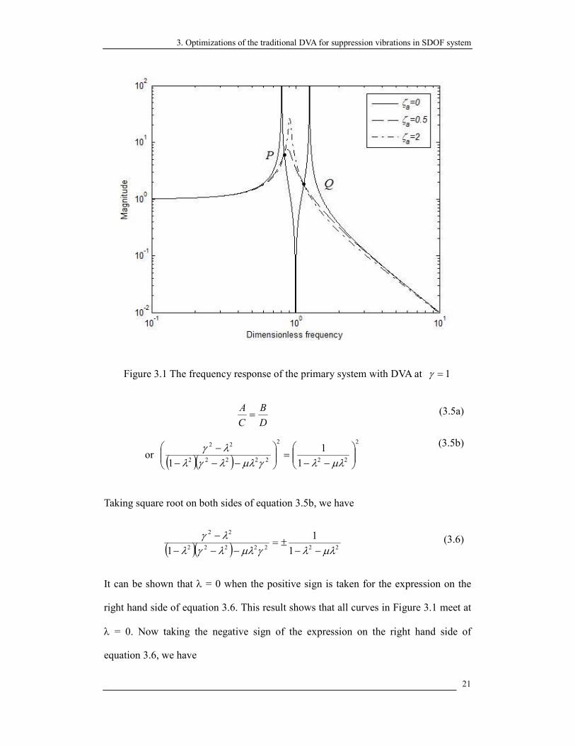
3. Optimizations of the traditional DVA for suppression vibrations in SDOF system
21
Figure 3.1 The frequency response of the primary system with DVA at 1=γ
D
B
C
A= (3.5a)
or ( )( )2
22
2
22222
22
1
1
1
−−=
−−−−
µλλγµλλγλλγ
(3.5b)
Taking square root on both sides of equation 3.5b, we have
( )( ) 2222222
22
1
1
1 µλλγµλλγλλγ
−−±=
−−−
− (3.6)
It can be shown that λ = 0 when the positive sign is taken for the expression on the
right hand side of equation 3.6. This result shows that all curves in Figure 3.1 meet at
λ = 0. Now taking the negative sign of the expression on the right hand side of
equation 3.6, we have

3. Optimizations of the traditional DVA for suppression vibrations in SDOF system
22
( )( ) 2222222
22
1
1
1 µλλγµλλγλλγ
−−−=
−−−
− (3.7)
Rewriting equation 3.7 as
02
2
2
222 22
224 =
++
+++
−µ
γλ
µµγγ
λ (3.8)
Equation 3.8 is a quadratic equation in 2λ . Let the two roots of equation 3.8 be 2
aλ
and 2
bλ where ba λλ <<0 . The sum and the product of the roots are respectively
written as
µµγγ
λλ+++
=+2
122
22
ba (3.9a)
and µ
γλλ
+=
2
2 222
ba (3.9b)
The amplitudes of the frequency response at these two roots are independent of the
damping ratio ζa, where these two points, P and Q, are called ‘fixed points’. The
amplitudes of the frequency response at 2
aλ and 2
bλ are
( )221
1
aa
aD
BH
µλλλ
−−==
(3.10a)
and ( )221
1
bb
bD
BH
µλλλ
−−==
(3.10b)
At any damping ratio, the frequency response must pass through these two fixed
points P and Q. So the optimum condition should obey the following equation:
( )( ) ( ) ( )( )
=∞∞ baHHa HHH
a
λλζγλζγ
,maxmin,,max,
(3.11)
The relation between the fixed points and tuning ratio is shown in figures 3.2 and 3.3.

3. Optimizations of the traditional DVA for suppression vibrations in SDOF system
23
Figure 3.2 The height of fixed points in the frequency response spectrum of mass
M versus tuning ratio γ at 2.0=µ
Figure 3.3 ( ) ( )( )ba HH λλζγ
,max,
versus tuning ratio γ at 2.0=µ

3. Optimizations of the traditional DVA for suppression vibrations in SDOF system
24
From figure 3.2 and figure 3.3, the minimum height of the fixed points is found when
the height of the fixed point P is equal to the fixed point Q, i.e. ( ) ( )ba HH λλ = . So
the fixed points of the frequency response are adjusted to the same, i.e.
2222 1
1
1
1
bbaa µλλµλλ −−−=
−− (3.12)
Using equations 3.9 and 3.10, the tuning ratio which let the amplitude of the fixed
points be the same is
µγ
+=∞
1
1H (3.13)
The frequency response using µ
γ+
=1
1 is shown in figure 3.4.
Figure 3.4 The frequency response of the primary mass M with DVA tuned at ∞Hγ

3. Optimizations of the traditional DVA for suppression vibrations in SDOF system
25
Substitute equation 3.13 into equation 3.8, we may write
( )( )0
12
2
1
22
24 =++
++
−µµ
λµ
λ (3.14)
The roots of equation 3.14 can be written as
+−
+=
µµ
µλ
21
1
12
a (3.15a)
and
++
+=
µµ
µλ
21
1
12
b (3.15b)
Substitute equation 3.15 into equation 3.12, the response amplitude at the fixed points
is
( ) ( )µµ
λλ+
===2
ba HHG (3.16)
In the above, the optimum tuning condition was deduced. The next step is to
determine the optimum damping in order to make the fixed points to become the
peaks on the response curve. We may write
( ) ( ) 02
2
2
2=
∂∂
=∂∂
== ba
HHλλλλ
λλ
λλ
(3.17)
Let
( )q
pH =
2λ (3.18)
Where ( ) ( )2222 2 γλζλγ ap +−= (3.19)

3. Optimizations of the traditional DVA for suppression vibrations in SDOF system
26
( )( )[ ] ( )[ ]222222222 121 µλλγλζγµλλγλ −−+−−−= aq (3.20)
Substitute (3.18) into (3.17), we may write
( ) 02
2
2=
∂
∂=
∂
∂q
pH
λλ
λ (3.21)
02
22
=∂∂
−∂∂
q
pq
qp
λλ
(3.22)
022
=∂∂
−∂∂
pq
qp
λλ (3.23)
Using equations 3.19 and 3.20, we may write
( ) ( )222
222 γζγλ
λ a
p+−=
∂∂
(3.24)
( )( )[ ]( )( ) ( )( )22222
22222222
2
33112
2112
µλλµλλγζ
µγγλγµλλγλλ
−−−−+
−−+−−−−=∂∂
a
q
(3.25)
Under the optimum tuning condition, we have
µµ+
==22
q
pG (3.26)
Therefore,
02
22=
∂∂
−∂∂
Gqp
λλ (3.27)
Solving equation 3.27 for 2ζ , we have
( )( )[ ]( ) ( )( ) ( ) ( )( ) 2222222
222222222222
221122
22112
G
Ga
µλλµλλγγγλµγγλγµλλγλ
ζ−−−−−
−−−−+−−−−= (3.28)
Substituting equations 3.13, 3.15 and 3.16 into the equation above, we find the

3. Optimizations of the traditional DVA for suppression vibrations in SDOF system
27
optimum damping written as
( )µ
µµ
µ
ζ+
+±
=18
23
a
(3.29)
Taking an average of aζ and the optimum tuning becomes
µγ
+=∞
1
1H
and ( )µ
µζζζ
+=
+=∞
18
3
2
22
baH
(3.30)
From equation 3.16, the resonant amplitude ratio is approximately
µµ+
=2
maxY
X
(3.31)
The frequency response of the primary mass M at 2.0=µ with different damping
ratios is shown in figure 3.5.
Figure 3.5 The frequency response of the primary system with DVA using the H∞
optimum tuning

3. Optimizations of the traditional DVA for suppression vibrations in SDOF system
28
In figure 3.5, the fixed points P and Q are close to the resonant response of the
primary system. Equation 3.2 can be satisfied and the primary system obey the
optimization requirement expressed as
( ) ( )µµ
λζγλζγ
+≈
≤∞∞
2maxmin,,
,HH
a
HH , where +ℜ∈λ (3.32)
This optimization is called H∞ optimization. With the same procedure, the optimum
tuning for the velocity and acceleration responses of the primary system can also be
found and they are tabulated in the following.
Table 3.1 The H∞ optimum tuning in a SDOF system
Transfer
function Tuning ratio Damping ratio
The height of
the fixed point
( ){ }( ){ }tyL
txL
µ+1
1
( )µµ+18
3
µµ+2
( ){ }( ){ }tyL
txL
nω&
2
2
1
1 µµ
++
( )
( )µ
µµµµ +
+++ 1
52424
24
1 2
( )µµµ
++
1
2
( ){ }( ){ }tyL
txL
n
2ω&&
µ+1
1
µµ+2
3
2
1
( )µµ +1
2
In fact, these optimum tunings based on the fixed point are not the exact solutions.
The exact H∞ optimum tunings were found by Nishihara and Asami [2] at 1997.
Nishihara and Asami provided different method to solve the H∞ optimum tunings.
However, based on their results [36], the error compared with the exact optimum
tunings and the approximated optimum tunings is under 1% when 1<µ . So these
results still have the significance of the people using the damped DVA.

3. Optimizations of the traditional DVA for suppression vibrations in SDOF system
29
3.2 H2 optimization of the traditional DVA for SDOF system
The dynamic absorber used to mitigate random excitation has very important practical
application particularly for tower structures, whose vibrations are caused by wind and
seismic loads. In this case, the single frequency excitation is not the case in these real
situations. A different optimization scheme should be considered.
Crandall and Mark (1963) proposed another optimization principle of the damped
DVA with the objective function on minimizing the total vibration energy of the
primary structure under white noise excitation, i.e.
[ ]( )2
,min xE
aζγ (3.33)
which called H2 optimization of dynamic vibration absorber. The exact solution of the
H2 optimization for the DVA attached to undamped primary system was derived by
Warburton (1980).
The frequency response functions of the SDOF system with a DVA are restated below
for the ease of discussion. The frequency response functions of the system excited by
an external force and the system excited by ground motions are written respectively as
( ) ( )( )[ ] ( )2222222
22
121
2
µλλγλζγµλλγλγλζλγ
λ−−+−−−
+−==
a
a
j
j
KF
XH
(2.16)
and ( ) ( )( )[ ] ( )2222222
22
121
2
µλλγλζγµλλγλγλζλγ
λ−−+−−−
+−==
a
a
j
j
Y
XH (2.19)
The mean square motion [ ]2xE of the stationary response process ( )tx can be
obtained when either the autocorrelation function ( )τxR or the spectral density
( )ωxS of the response is known according to the following formulae:

3. Optimizations of the traditional DVA for suppression vibrations in SDOF system
30
( ) [ ]20 xERx = (3.34)
[ ] ( )∫∞
∞−= ωω dSxE x
2 (3.35)
The autocorrelation function of the response and the spectral density are written as
( ) ( ) ( ) ( )∫ ∫∞
∞−
∞
∞−−+= 212121 θθθθθθττ ddhhRR yx (3.36)
( ) ( ) ( )ωωω yx SHS2
= (3.37)
Thus the mean square motion can be written as
[ ] ( ) ( ) ( ) ( )∫ ∫∞
∞−
∞
∞−−== 212121
2 0 θθθθθθ ddhhRRxE yx (3.38)
The mean square motion can be written in terms of the input mean square spectral
density ( )ωyS as
[ ] ( ) ( ) ( )∫∫∞
∞−
∞
∞−== ωωωωω dSHdSxE yx
22 (3.39)
If the input spectrum is assumed to be ideally white, i.e. ( ) 0SS y =ω , a constant for
all frequencies, the integral of equation 3.39 can then be reduced to
[ ] ( )∫∞
∞−= ωω dHSxE
2
0
2 (3.40)
Using equation 3.40, the non-dimensional mean square motion can be defined as
[ ] ( )∫∞
∞−= λλ
πω
dHS
xE n 202
2 (3.41)
Substituting equation 2.19 into equation 3.41, the equation can be written as,

3. Optimizations of the traditional DVA for suppression vibrations in SDOF system
31
[ ] ( )( )[ ] ( )∫∞
∞− −−+−−−
+−= λ
µλλγλζγµλλγλγλζλγ
πω
dj
jSxE
a
an
2
2222222
22
02
121
2
2
(3.42)
Two useful formulae as shown below from Gradshteyn and Ryzhik (1994) are used to
solve equation 3.41.
If ( )012
2
3
3
4
4
012
2
3
3
AAjAAjA
BBjBBjH
++−−
++−−=
ωωωωωωω
ω (3.43a)
then ( )
( ) ( )
( ) ( )
( )∫∞
∞− −−
−+−+
−+−
=2
3041321
3021
4
2
331
2
21
20
2
134132
0
2
0
2
2
2
AAAAAAA
AAAAA
BBBBA
BBBAAAAAA
B
dH πωω
(3.43b)
Comparing equation 3.42 and equation 3.43, the equation can be written as
( )0,1,2,
1,12,1,2,
321
2
0
43
22
21
2
0
====
=+=++===
BBBB
AAAAA
a
a
γζγ
µζγµγγγζγ
(3.44)
Using equations 3.43 and 3.44, the mean square motion in equation 3.42 can be
written as
[ ] ( ) ( )( )[ ]121414
224202 +−−+++= γµµζγµγµζ
ωa
a
n SxE (3.45)
If [ ] [ ] 022 =∂∂
=∂∂
xExEaζγ
exists, the system will have an optimum tuning condition.
The derivatives of equation 3.45 may be written as
[ ] ( ) ( )( )[ ]1214134
2242
2
02 −−−+++=∂∂
γµµζγµγµζ
ωγ a
a
n SxE (3.46a)
and [ ] ( ) ( )( )[ ]121414
2242
22
02 −+++++−=∂∂
γµµζγµγµζ
ωζ a
a
n SxE (3.46b)

3. Optimizations of the traditional DVA for suppression vibrations in SDOF system
32
Using equations 3.46a and 3.46b, the optimum tuning can be found as
( )2212
2
+
+=
µµ
γ H and ( )
( )( )122
43
2
12 ++
+=
µµµµ
ζ H (3.47)
This optimization is called H2 optimization. The optimum tuning of the velocity
response can also be found using a similar procedure and the tuning frequency and
damping ratios are shown in the following table.
Table 3.2 The H2 optimum tuning in a SDOF system
Transfer
function
Tuning
frequency ratio Damping ratio
Optimized value of
performance index
[ ]2xE ( )2
12
2
+
+
µµ
( )
( )( )122
43
2
1
+++µµ
µµ
( )µµµ
++1
34
2
1
[ ]2xE & µ+1
1
2
µ ( )µµ +1
1
This H2 optimum tuning can minimize the mean square motion of the undamped
primary system under a white noise excitation and this result is an exact solution of
the H2 optimization problem.

3. Optimizations of the traditional DVA for suppression vibrations in SDOF system
33
3.3 Summary
H∞ optimization and H2 optimization are introduced and the analytical solutions
including the tuning frequency and damping ratios of the DVA for these optimization
problems in SDOF system are derived.
From table 3.1 and table 3.2, the tuning ratios and the damping ratios of the motion
are
µγ
+=∞
1
1H and
( )µµ
ζ+
=∞18
3H
(3.30)
( )2212
2
+
+=
µµ
γ H and ( )
( )( )122
43
2
12 ++
+=
µµµµ
ζ H (3.47)
The graphs of both tuning ratio and damping ratio versus mass ratio of the DVA are
plotted in figures 3.6 and 3.7, respectively.
0 0.2 0.4 0.6 0.8 10.5
0.6
0.7
0.8
0.9
1
Mass ratio
Tuning ratio
H∞ optimization
H2 optimization
Figure 3.6 Mass ratio vs. tuning ratio in different optimization methods
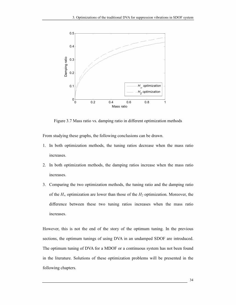
3. Optimizations of the traditional DVA for suppression vibrations in SDOF system
34
0 0.2 0.4 0.6 0.8 10
0.1
0.2
0.3
0.4
0.5
Mass ratio
Damping ratio
H∞ optimization
H2 optimization
Figure 3.7 Mass ratio vs. damping ratio in different optimization methods
From studying these graphs, the following conclusions can be drawn.
1. In both optimization methods, the tuning ratios decrease when the mass ratio
increases.
2. In both optimization methods, the damping ratios increase when the mass ratio
increases.
3. Comparing the two optimization methods, the tuning ratio and the damping ratio
of the H∞ optimization are lower than those of the H2 optimization. Moreover, the
difference between these two tuning ratios increases when the mass ratio
increases.
However, this is not the end of the story of the optimum tuning. In the previous
sections, the optimum tunings of using DVA in an undamped SDOF are introduced.
The optimum tuning of DVA for a MDOF or a continuous system has not been found
in the literature. Solutions of these optimization problems will be presented in the
following chapters.

4. Optimizations of the traditional DVA for suppression vibrations in beam structures
35
4. OPTIMIZATIONS OF THE TRADITIONAL DVA FOR
SUPPRESSION VIBRATIONS IN BEAM STRUCTURES
Optimization theory of the traditional DVA for suppressing vibrations in beam
structures is presented in this chapter. Beam structure is a very common structure
in engineering application such as building and bridge.
The beam structure is considered as a MDOF or continuous vibrating system.
The beam has more than one resonant frequency. Another different consideration
in applying a DVA between the SDOF and the beam vibrating systems is that the
DVA can be attached at different location on the beam and the effect of vibration
suppression can be very different. So new problems in this case are what is the
good position of attaching DVA and what is the difference of the optimum tuning
frequency and damping ratios when the attaching position is changed? In this
part, the research of DVA optimizations includes the reduction of vibration at a
particular point on the beam and the total kinetic energy of the beam structure.
All discussions are based on the assumptions listed below.
1. The beam is assumed to be an Euler-Bernoulli beam.
2. The dynamic response of the beam is due to the dominant mode only,
i.e. single mode response only, and the responses of other modes may
be ignored.
3. The modes can be well separated.
The reason of using the Euler-Bernoulli beam is that the dominant modes of the
structure are always in the lower modes. In these modes, the effects of shear

4. Optimizations of the traditional DVA for suppression vibrations in beam structures
36
deformation and rotational inertia are not large. According to these reasons, the
advance beam model, such as Timoshenko beam, is not used in my calculation.
An approximated H∞ optimum tuning and H2 optimum tuning conditions are
derived analytically and compared to the results reported by another researcher
(Dayou 2006) who has applied a different approach to the problem.
The error of the approximated optimum tunings are shown in section 4.4 and the
effect of the non-tuned mode is discussed in section 4.5.

4. Optimizations of the traditional DVA for suppression vibrations in beam structures
37
4.1 The frequency response function of the beam structure with
the traditional DVA
Referring to figure 4.1, consider the motion of a cantilever beam due to the
distributed force applying between x = 0 and oxx = . A DVA is attached at
oxx = . The length of the beam is L, mass per unit length ρA, with bending
stiffness EI. The boundary conditions are any combination of pinned, clamped or
free supports. The Euler-Bernoulli equation can be written in equation 4.1 and
the detail of derivation of this equation is shown in Appendix A.
)()()()(4
4
2
2
oxxtFxgtpx
wEI
t
wA −+=
∂∂
+∂∂
δρ (4.1)
Figure 4.1 The cantilever beam with a DVA under a external force
Here it has been assumed that the externally applied forcing function can be
expressed as )()( xgtp , where p(t) is a function of time and g(x) is a
deterministic function of x. The solution to equation 4.1 can be expanded in a
Fourier series written as

4. Optimizations of the traditional DVA for suppression vibrations in beam structures
38
∑∞
=
=1
)()(),(i
ii xtqtxw ϕ (4.2)
where ( ) LdxxL
i =∫02
)(ϕ
where )(xiϕ is the eigenfunction of the beam without the DVA. Similarly, the
spatial part of the forcing function can be expanded as
∑∞
=
=1
)()(i
ii xaxg ϕ (4.3)
The Dirac delta functions can also be expanded as
∑∞
=
=−1
)()(i
iio xbxx ϕδ (4.4)
where the Fourier coefficients ia and
ib are respectively
∫=L
ii dxxxgL
a0
)()(1
ϕ and L
xb oi
i
)(ϕ= (4.5)
Here ia depends only on the spatial distribution of the forcing function g(x). If
the equations 4.2, 4.3 and 4.4 are substituted into equation 4.1 and Laplace
transformation is taken on the resulting equation with respect to time, the
transformed result is a set of algebraic equations written as
( ) ( ) ( ) ( ) NisFbsPasQEIsQAs iiiii ∈+=+ 42 βρ (4.6)
where ∑∞
=
=∂
∂
1
4
4
4
)()(i
iii xtqx
wϕβ (4.7)
If this is solved for the generalized co-ordinates ( )sQi , the result may be written
as

4. Optimizations of the traditional DVA for suppression vibrations in beam structures
39
( ) ( ) ( )42
i
ii
iEIAs
sFbsPasQ
βρ +
+= (4.8)
Then if P(s) and F(s) were known then the s-domain motion of any point on the
beam could be given as
( ) ( ) ( )∑∞
= +
+=
142
)(,
i
i
i
ii xEIAs
sFbsPasxW ϕ
βρ (4.9)
where ( )sxW , is the Laplace transform of ( )sxw , with respect to time. For a
damped DVA, the transfer function between the motion at the attachment point
with the DVA, ( )sxW o , , and the force transmitted to the beam, ( )sF , is written
as equation 4.10 below and the proof is shown in Appendix B.
( )( )
( )kcsms
kcsms
sxW
sF
o +++
−=2
2
, (4.10)
Substitute equation 4.10 into 4.9, we have
∑∞
= +++
+−
=1
42
2
2
)(
)(),()(
),(i
i
i
oii
xEIAs
kcsms
kcsmssxWbsPa
sxW ϕβρ
(4.11)
When oxx = , equation 4.11 becomes,
∑∑∞
=
∞
= ++++
−+
=1
422
2
142
)()(),(
)()(),(
i i
oiio
i i
oiio
EIAs
xb
kcsms
kcsmssxW
EIAs
sPxasxW
βρϕ
βρϕ
(4.12)
∑
∑∞
=
∞
=
++++
+
+=⇒
1422
2
142
)()(1
)()(
),(
i i
oii
i i
oii
o
EIAs
xb
kcsms
kcsms
EIAs
sPxa
sxW
βρϕ
βρϕ
(4.13)
Substitute (4.13) into (4.11), we have the following transfer function:

4. Optimizations of the traditional DVA for suppression vibrations in beam structures
40
∑∑
∑
∞
=
∞
=
∞
=
+
++
+++
+−
=1
42
1422
2
142
)(
)(
)(
)(
)(
),(
i
i
i
i i
oii
i i
oii
ii
xEIAs
EIAs
xb
kcsms
kcsms
EIAs
xa
ba
sP
sxWϕ
βρβρ
ϕβρ
ϕ
(4.14)
Replacing ωjs = where 1−=j in equation 4.14 for the steady-state
response of the beam and rewrite the resulting equation in a non-dimensional
form as
( )( ) ∑
∑
∑
∞
=
∞
=
∞
=
−
−+
+
−+−
−−
=1
22
12222
22
122
2)(
)(
)2(
2
)(
1,
i
i
i
i i
oii
a
a
i i
oii
ii
n
x
xbL
j
j
xaL
ba
AP
xWϕ
λγλγ
ϕµ
γγλζλλγγλζ
λγϕ
µ
ωρλλ
(4.15)
Similarly, the transfer functions of the velocity and the acceleration response at
the point x on the beam structure can be rewritten, respectively, as
( ){ }( ){ }
( )( )λ
λλ
ω P
xWj
tpL
txwL
n
,,=
& (4.16)
and ( ){ }
( ){ }( )( )λ
λλ
ω P
xW
tpL
txwL
n
,, 2−=&&
(4.17)

4. Optimizations of the traditional DVA for suppression vibrations in beam structures
41
4.2 Optimization for minimizing the vibration at a point on the
beam structure
For a beam structure with well-separated natural frequencies, the modal
displacement response in the vicinity of the nth
natural frequency may be
approximated by considering i = n and ignoring other modes in the equation
4.15. Consider i = n and ignoring other modes, equation 4.15 may be rewritten
as
( )( )
)(1
1
)(
)2(
2
1
)(
1,2
222
22
2
2x
xbL
j
j
xaL
ba
AP
xWn
onn
a
a
onn
nn
n
ϕλ
λϕ
µγγλζλλγγλζ
λϕ
µ
ωρλλ
−
−+
+
−+−
−−
=
(4.18)
Equation 4.18 can be simplified as
( )( )
( )( )( )[ ] ( )2222222
22
2 121
2,
ελλγλζγελλγλγλζλγ
ωρϕ
λλ
−−+−−−
+−=
a
a
n
nn
j
j
A
xa
P
xW (4.19)
where ( )0
2 xnµϕε =
Equation 4.19 can be rewritten in a form as
( )( )
( ) ( )λωρ
ϕλλ
HA
xa
P
xW
n
nn
2
,= (4.21)
where
( ) ( )( )[ ] ( )2222222
22
121
2
ελλγλζγελλγλγλζλγ
λ−−+−−−
+−=
a
a
j
jH (4.20)

4. Optimizations of the traditional DVA for suppression vibrations in beam structures
42
In considering H∞ optimization, the objective is to minimize the maximum
amplitude ratio of the response of the primary system to the excitation force or
motion, i.e.
( )( )
( )( )
=
∞∞
λλ
λζγλ
ζγ P
xW
P
xW
a
HH ,maxmin
,,,max
, (4.22)
It is noted that only the function ( )λH is required to be considered in the
optimization because ( )
2
n
nn
A
xa
ωρϕ
is a constant term. The objective function of
the optimization may be written as
( )( )
( ) ( )( )∞∞∞∞ ≈
HH
n
nnHH HA
xa
P
xWζγλ
ωρϕ
λζγλ
,,max,,,
max2
(4.23)
The equation 4.20 is equivalent to the equation 2.19 in the SDOF system
attached with a DVA if the term ε in equation 4.20 is replaced by the mass ratio µ.
Therefore, applying the fixed-points theory, the optimum tuning can be found in
the same way as the case of SDOF system and the result are listed in Table 4.1
Table 4.1 The H∞ optimum tuning at a point x in the beam structure
Transfer
function Tuning ratio Damping ratio
The height of the
fixed point
( ){ }( ){ }tpL
twL
ε+1
1
( )εε+18
3
( )εε
ωρϕ +2
2
n
nn
A
xa
( ){ }( ){ }tpL
twL
nω&
2
2
1
1 εε
++
( )
( )ε
εεεε +
+++ 1
52424
24
1 2
( )
( )εεε
ωρϕ
++
1
22
n
nn
A
xa
( ){ }( ){ }tpL
twL
n
2ω&&
ε+1
1
εε+2
3
2
1
( )( )εεωρ
ϕ+1
22
n
nn
A
xa

4. Optimizations of the traditional DVA for suppression vibrations in beam structures
43
Similarly, for the H2 optimization of searching the DVA parameters for
suppressing vibration of a beam structure, the objective is to minimize the total
vibration energy of the beam structure at the point x at all frequencies. The
performance index can be defined as
( )[ ]( )twEa
2
,min
ζγ (4.24)
The mean square motion can be written in terms of the input mean square
spectral density ( )ωpS as
( )[ ] ( ) ( )( )
( )∫∫∞
∞−
∞
∞−== ωω
ωω
ωω dSP
WdStwE pw
2
2 (4.25)
If the input spectrum is assumed to be ideally white, i.e. ( ) 0SS p =ω , a constant
for all frequencies, the integral of equation 4.25 can then be reduced to
[ ] ( )( )∫
∞
∞−= ω
ωω
dP
WSwE
2
0
2 (4.26)
Using equation 4.26, the non-dimensional mean square motion can be defined as
[ ] ( )( )
( ) ( )∫∫∞
∞−
∞
∞−
≈= λλ
ωρϕ
πω
λωω
πω
dHA
xaSd
P
WSxE
n
nnnn 2
2
2
0
2
02
22 (4.27)
Similarly, equation 4.20 is equivalent to the equation 2.19 in the SDOF system
attached with a DVA if the term ε in equation 4.20 is replaced by the mass ratio µ.
Therefore the optimum DVA parameters can be found in the same way as in the
case of the SDOF system and the result are listed in Table 4.2.

4. Optimizations of the traditional DVA for suppression vibrations in beam structures
44
Table 4.2 The H2 optimum tuning at a point x in a beam structure
Transfer
function Tuning ratio Damping ratio
Optimized value of
performance index
( )[ ]twE 2 ( )2
12
2
+
+
εε
( )
( )( )122
43
2
1
+++εε
εε
( )( )εε
εωρ
ϕ+
+1
34
2
12
n
nn
A
xa
( )[ ]twE 2&
ε+1
1
2
ε
( )( )εεωρ
ϕ+1
12
n
nn
A
xa

4. Optimizations of the traditional DVA for suppression vibrations in beam structures
45
4.3 Optimization for minimizing the root mean square motion
over the whole domain of the beam structure
Equation 4.15 is restated below for the ease of discussion.
( )( ) ∑
∑
∑
∞
=
∞
=
∞
=
−
−+
+
−+−
−−
=1
22
12222
22
122
2)(
)(
)2(
2
)(
1,
i
i
i
i i
oii
a
a
i i
oii
ii
n
x
xbL
j
fj
xaL
ba
AP
xWϕ
λγλγ
ϕµ
γγλζλλγγζ
λγϕ
µ
ωρλλ
(4.15)
The root mean square motion over the whole domain of the beam structure may
be written as
( )( )
dxx
xbL
j
fj
xaL
ba
A
dxP
xW
L
i
i
i
i i
oii
a
a
i i
oii
ii
n
L
2
01
22
12222
22
122
2
2
0
2
)(
)(
)2(
2
)(
1
,
∫ ∑∑
∑
∫
−
−+
+
−+−
−−
=
∞
=
∞
=
∞
=
ϕλγ
λγϕ
µγγλζλλγγζ
λγϕ
µ
ωρ
λλ
(4.28)
Consider the orthogonality relations of the eigenfunctions, we may write
( ) ( ) 00
=∫L
nm dxxx ϕϕ if nm ≠ (4.29a)
and ( ) ( ) LdxxxL
nm =∫0 ϕϕ if nm = (4.29b)

4. Optimizations of the traditional DVA for suppression vibrations in beam structures
46
Equation 4.28 can be simplified with the above orthogonality relations of the
eigenfunctions as
( )( )
2
122
12222
22
122
2
0
2
)(
)2(
2
)(
,
−
−+
+
−+−
−−
=
∑∑
∑
∫
∞
=
∞
=
∞
=
i i
i i
oii
a
a
i i
oii
ii
n
L
xbL
j
fj
xaL
ba
A
L
dxP
xW
λγλγ
ϕµ
γγλζλλγγζ
λγϕ
µ
ωρ
λλ
(4.30)
For a beam structure with well-separated natural frequencies, the modal
displacement response in the vicinity of the nth
natural frequency may be
approximated by considering i = n and ignoring other modes in equation 4.30
and written as
( )( )
2
2
222
22
2
20
2
1
1
)(
)2(
2
1
)(
,
−−
++−+
−
−−
=
∫ λ
λϕ
µγγλζλλγγζ
λϕ
µ
ωρλλ
onn
a
a
onn
nn
n
L
xbL
j
fj
xaL
ba
A
Ldx
P
xW (4.31)
Equation 4.31 can be simplified as

4. Optimizations of the traditional DVA for suppression vibrations in beam structures
47
( )( )
( )( )[ ] ( )2222222
22
2
0
2
121
2
,
ελλγλζγελλγλγλζλγ
ωρ
λλ
−−+−−−
+−=
∫
a
a
n
n
L
j
j
A
La
dxP
xW
(4.32)
where ( )0
2 xnµϕε =
Equation 4.32 can be rewritten in a form as
( )( )
( )λωρλ
λH
A
Ladx
P
xW
n
nL
20
2
,=
∫ (4.34)
where
( ) ( )( )[ ] ( )2222222
22
121
2
ελλγλζγελλγλγλζλγ
λ−−+−−−
+−=
a
a
j
jH (4.33)
In solving the H∞ optimization problem, the objective function is to minimize the
maximum amplitude ratio between the response of the primary system relative
and the excitation force or motion, i.e.
( )( )
( )( )
=
∫∫ ∞∞
LLHH dx
P
xWdx
P
xW
a0
2
,0
2
,maxmin
,,,max
λλ
λζγλ
ζγ (4.35)
It is noted that only the function ( )λH is required to be considered in the
optimization because 2
n
n
A
La
ωρ is a constant term. The objective function may
be rewritten as
( )( )
( )
=
∫ ∞∞ λ
ωρλζγλ
ζγH
A
Ladx
P
xW
an
nL
HH
,20
2
maxmin,,,
max (4.36)

4. Optimizations of the traditional DVA for suppression vibrations in beam structures
48
Equation 4.33 is equivalent to equation 2.19 in the SDOF system attached with a
DVA if the term ε in equation 4.33 is replaced by the mass ratio µ. Therefore, by
applying the fixed-points theory, the optimum parameters of the DVA can be
found in the same way as in the case of the SDOF system and the result are
listed in Table 4.3.
Table 4.3 The H∞ optimum tuning of the root mean square motion of the beam
structure
Transfer function Tuning ratio Damping ratio The height of the
fixed point
( ){ }( ){ }∫
L
dxtpL
twL
0
2
ε+1
1
( )εε+18
3
εε
ωρ+2
2
n
n
A
La
( ){ }( ){ }∫
L
n
dxtpL
twL
0
2
ω&
2
2
1
1 εε
++
( )
( )ε
εεεε +
+++ 1
52424
24
1 2
( )εεε
ωρ ++
1
22
n
n
A
La
( ){ }( ){ }∫
L
n
dxtpL
twL
0
2
2ω&&
ε+1
1
εε+2
3
2
1 ( )εεωρ +1
22
n
n
A
La
Similarly, in searching the H2 optimization solution of the DVA for suppressing
vibration in a beam structure, the performance index can be defined as
( ){ }( ){ }
∫
L
dxtpL
twLE
a 0
2
,min
ζγ (4.37)
Following equations 4.25, 4.26 and 4.27, the optimum DVA parameters can be
found in the same way as in the case of the SDOF system and the result are
listed in Table 4.4

4. Optimizations of the traditional DVA for suppression vibrations in beam structures
49
Table 4.4 The H2 optimum tuning of the root mean square motion of the beam
structure
Transfer function Tuning ratio Damping ratio Optimized value of
performance index
( ){ }( ){ }
∫
L
dxtpL
twLE
0
2
( )2
12
2
+
+
εε
( )
( )( )122
43
2
1
+++εε
εε
( )εεε
ωρ ++1
34
2
12
n
n
A
La
( ){ }( ){ }
∫
L
dxtpL
twLE
0
2&
ε+1
1
2
ε ( )εεωρ +1
12
n
n
A
La

4. Optimizations of the traditional DVA for suppression vibrations in beam structures
50
4.4 Numerical Simulation
A simply supported Euler beam attached with a DVA as illustrated in Figure 4.2
is considered in the following numerical study. The eigenfunctions and the
eigenvalues can be written as
)sin(2
)( xL
x iβϕ = (4.38)
where NiL
ii ∈=
πβ
The reciprocal of the denominator integral is
∫ ==L
ii
LdxxK
0
2
2)(sin β (4.39)
)sin(2 1
L
xi
Lai
π= and )sin(
2
L
xi
Lb o
i
π= (4.40)
Figure 4.2 The simply supported beam with DVA under a concentrated force
The material of beam is assumed to be aluminum of density and Young’s

4. Optimizations of the traditional DVA for suppression vibrations in beam structures
51
modulus 2710 kg/m3 and 6.9GPa, respectively. The mass ratio µ is 0.2. The
dimensions of the beam are 1m (length) X 0.025m (Width) X 0.0025m (height).
x0 is 0.3m and x1 is 0.2m.
As shown in figure 4.3, the maximum response of the beam at x0 without
damping is much higher than the maximum response of the beam using the
optimum tuning frequency and damping of the DVA. Moreover, the second
resonance of the beam at x0 can also be suppressed.
As shown in figure 4.4, the optimum tuning parameters presented in the previous
section are applied and the resulting frequency response of the beam is compared
to the one using the optimum DVA parameters suggested by Den Hartog (1985).
The maximum response of the system can be reduced by more than 20% in this
case.
0 1 2 3 4 5 6 7 8 9 1010
-6
10-5
10-4
10-3
10-2
10-1
100
101
102
Non - dimensional frequency
Frequency response
Frequency response in the simply support beam in optimum tuning
Using new optimum tuning (3.31)
Light damping
Figure 4.3 Frequency responses of the beam at x = x0 with very light damping and
optimum tuning frequency and damping in the DVA

4. Optimizations of the traditional DVA for suppression vibrations in beam structures
52
0 1 2 3 4 5 6 7 8 9 1010
-6
10-5
10-4
10-3
10-2
10-1
100
Non - dimensional frequency
Frequency response
Frequency response in the simply support beam in optimum tuning
Using new optimum tuning (3.31)
Optimum damping of Den Hartog (2.1.2)
Figure 4.4 Frequency responses of the beam at x = x0 with the proposed optimum
parameters of the DVA and the ones made by Den Hartog.
To test the usefulness of the derived H∞ optimization solution for suppressing
vibrations a continuous vibrating system, the numerical testing case for the
minimization of the maximum kinetic energy of a vibrating beam reported by
Dayou (2006) was studied by applying the present theory and the result was
compared to those obtained by Dayou. The vibrating beam considered by Dayou
was a simply supported aluminum beam excited by a point force of unit
amplitude at L1.0 as shown in figure 4.5. The eigenfunctions and eigenvalues
of the beam could be written respectively as (Srinivasan 1982)
)sin()(L
xpxp
πϕ = , p = 1, 2, 3…, and (4.41)
=A
EI
L
pp ρ
πω
42
, p = 1, 2, 3… (4.42)
where L = 1 m, E = 207 GPa, I = 10101295.8 −× m4, ρ = 7870 kg/m
3 and A =
2.42 x 10⁻⁴
m2. A dynamic vibration absorber was attached at Lxo 5.0= and

4. Optimizations of the traditional DVA for suppression vibrations in beam structures
53
mass ratio, µ was 0.05.
Figure 4.5 Schematics of a simply supported beam with a vibration absorber
excited by a random force at x= 0.1L.
From equations (4.2) and (4.5), we have
∫
∫
−
=L
L
p
dxL
xp
dxL
xpxx
a
0
2
0 1
sin
sin)(
π
πδ
=
L
xp
L
1sin2 π
(4.43a)
∫
=L
o
p
dxL
xp
L
xp
b
0
2sin
sin
π
π
=L
xp
L
oπsin
2, p = 1, 2, 3… (4.43b)
The optimization problem could be expressed as
=
= ∫∫
∞
L
Tf
L
Tf
velbeam
dxfW
fxjfUdx
fW
fxU
H
0
2
1,0
2
1,
__
)(
),(supinf
)(
),(supinf
ωω ζζ
& (4.44)
where
+−−−++−
=
)2()1)(2(
2
)(
),(22222
22
2
1
1
TTfjfffTTfj
TfjfT
h
La
fW
fxU
aa
a
ζεζζ
ωρ
(4.45)

4. Optimizations of the traditional DVA for suppression vibrations in beam structures
54
and )(21 oxµϕε = which was the one-dimensional version of the ε used in the
theory section.
According to Dayou (2006), the optimum frequency and damping ratios were
ε+1
1 = 0.8333 and
)1(8
3
εε+
= 0.25 respectively. Based on the present
theory and the derived expressions of the optimum frequency and damping ratios
for H∞ optimization with different types of transfer functions as shown in Table
4.3, the frequency and damping ratios for minimum kinetic energy amplitude of
the plate were T = 2
2
1
1 εε
++
= 0.8740, and aζ =
( )( )
εεεε
ε +++
+ 1
52424
24
1 2
= 0.2498 respectively. Kinetic energy amplitudes
of the whole beam at steady state were calculated at different excitation
frequencies according to equation:
( )∑∑
∑
∫
=
=
=
−
−+
+
−−
−−
=
max
max
max
1222
2
12222
2
122
2
2
1
2
1
0
22
1
),(
)2(
2
)(
2
)(
),(
2
p
pp
p
p p
oopp
a
a
p
p p
opp
p
p
L
f
f
yxbL
TTfjf
TTfjf
f
xaLb
a
h
Lfh
dxfW
fxUh
γ
γ
ϕµ
ζζ
γ
ϕµ
ωρωρ
ωρ
(4.46)
A Matlab program is written to calculate these kinetic energy amplitudes and the
results were plotted in figure 4.6(a). Ten vibration modes (pmax = 10) of the beam
were used in the calculation. The kinetic energies of the beam calculated based
on the present theory and that by Dayou were plotted in Figure 4.6(a) for
comparison.

4. Optimizations of the traditional DVA for suppression vibrations in beam structures
55
The amplitude of the kinetic energy at the first resonance of the beam was
suppressed after adding the vibration absorber. However, it could be observed
in Figure 4.6(b), a close-up of the spectrum around the first natural frequency of
the beam, the heights of the two peaks of the curve of Dayou had a big
difference indicating that the damping and frequency ratios of the absorber were
not optimal based on the fixed-points theory. The maximum amplitude of the
kinetic energy of the whole beam around the first natural frequency of the beam
calculated with the proposed frequency and damping ratios was found to be
about 32% smaller than that of the beam with the frequency ratio (T = 0.8333)
and damping ratio (ζ = 0.25) used by Dayou.

4. Optimizations of the traditional DVA for suppression vibrations in beam structures
56
Figure 4.6 Kinetic energy (in J/N2) of a simply supported with optimum
vibration absorber fitted at xo = 0.5L with the first natural frequency as the
control target: (a) figure showing all three modes; (b) in the vicinity of the first
mode. --------- T = 0.8333, ζ = 0.25 (Dayou 2006), ———— T = 0.8775, ζ =
0.2556 (present theory)
The exact values of tuning frequency and damping ratios to minimize the
maximum amplitude of the kinetic energy of the whole beam around the first
natural frequency of the beam were determined numerically with equation 4.15
as T = 0.8775 and ζ = 0.2556. The difference of this maximum amplitude of
kinetic energy in using the proposed and the exact sets of T and ζ was found to
be about 3%.

4. Optimizations of the traditional DVA for suppression vibrations in beam structures
57
4.5 Effect of the tuned DVA in other modes
The approximated optimum tunings are derived for the dominant mode only.
However, the DVA under the approximated optimum tunings also affects other
modes. In this part, the effect of the attached DVA on other modes of the
structure is discussed.
Consider the transfer function of the DVA represented by equation (4.10) and
substituting ωjs = in equation (4.10), the steady state frequency response
function of the beam at the attachment point can be written as
( )( ) ωω
ωωω
ωjcmk
jmcmk
xW
F
o +−
+=
2
32
, (4.47)
Equation (4.47) may be rewritten as
( ) ( )ωωωωωωω
ee cjkjcmk
jmcmk−−≡
+−
+2
32
(4.48)
where ( ) ( ) ( )( ) ( )222
2222
ωω
ωωωω
cmk
cmmkmkke
+−
+−−= and
( )( ) ( )222
42
ωω
ωω
cmk
cmce
+−=
or rewriting in non-dimensional form as
( )( )
( ) ( ) ( ) ( )λλγλζλγγλζλγ
γγλζλλω
λeee
a
a
on
jj
j
xWm
F2
2
2
,
2
22
22
2+≡
+−
+= (4.49)
where ( ) ( )2
n
ee
m
k
ωλ
λγ = and ( ) ( )( )λ
λλζ
e
ee
mk
c
2=
where ( )ωek and ( )ωec are equivalent spring stiffness and equivalent

4. Optimizations of the traditional DVA for suppression vibrations in beam structures
58
damping coefficient at the exciting frequency ω respectively. The physical
meanings of these values are that the effect of the DVA attached to the structure
at the exciting frequency ω is same as the structure with the spring and the
damper, with the spring stiffness equals to ke and the damping coefficient equals
to ce, at the same position of the DVA attached and under the same exciting
frequency ω as illustrated in figure 4.7.
Consider the example in the previous section. The mass of the DVA is 0.3388kg,
the damping coefficient is sNm 11429.18 − and the spring stiffness is
1885.1 −kNm . The equivalent stiffness and damping at different excitation
frequency are calculated according to equation (4.48) and plotted in figure 4.8.
Figure 4.7 The cantilever beam with an equivalent spring and an equivalent
damper under a external force

4. Optimizations of the traditional DVA for suppression vibrations in beam structures
59
0 200 400 600 800 1000 1200 1400 1600 1800 2000-3000
-2000
-1000
0
1000
Frequency
Equivalent stiffness
0 200 400 600 800 1000 1200 1400 1600 1800 20000
20
40
60
Frequency
Equivalent damping coefficient
Figure 4.8 The equivalent stiffness and the equivalent damping coefficient of the
DVA
In the example of the previous section, the natural frequencies of the beam
without DVA are 113.7Hz, 454.6Hz, 1022.9Hz and 1818.5Hz. And the
equivalent stiffness and the damping coefficient at these resonant frequencies are
listed below.
Table 4.5 The equivalent stiffness and damping coefficient in the resonant
frequencies
Mode Natural
frequency
(Hz)
Equivalent
stiffness (Nm-1
)
Equivalent damping
coefficient (Nm-1
s)
1 113.7 186.56 33.21
2 454.6 897.77 18.88
3 1022.9 910.43 18.28
4 1818.5 912.40 18.19

4. Optimizations of the traditional DVA for suppression vibrations in beam structures
60
The frequency response function of the beam at the attachment point using the
equivalent stiffness and equivalent damping coefficient are plotted in figure 4.9.
Two cases are compared in the followings: one is the cantilever connected with a
DVA at the free end while the other is the equivalent system as illustrated in
figure 4.7. The frequency response function at the attachment point are
calculated and plotted in figure 4.9 for comparison.
0 200 400 600 800 1000 1200 1400 1600 1800 200010
-12
10-11
10-10
10-9
10-8
10-7
Frequency
Frequecny response of displacement
With DVA under Hinf optimum tuning
With ke and ce at the second mode
Figure 4.9 The primary system with the equivalent spring and damper
In figure 4.9, it can be seen that the response of the two curves are almost
overlapped together at all modes except the first mode. This shows that the
equivalent system in figure 4.7 can be used to represent the cantilever beam

4. Optimizations of the traditional DVA for suppression vibrations in beam structures
61
attached with the DVA for the frequency response at vibration modes other than
the tuned mode of the DVA. In figure 4.8, it is observed that the equivalent
damping coefficient is larger than the original damping coefficient in the DVA,
i.e. sNmc 11429.18 −= when the natural frequency is higher than the natural
frequency of the first mode and it approach to c as excitation frequency
approaching infinity. That means the tuned DVA does not only have an effect in
the dominant mode but it also has a damper effect in other higher order modes.
The proposed equivalent vibrating system may be used to represent the effect of
the DVA to the response of the higher order modes of the vibrating beam which
is neglected in the analysis of the previous sections of this chapter.

4. Optimizations of the traditional DVA for suppression vibrations in beam structures
62
4.6 Conclusion in the optimization of DVA for suppressing
vibrations in beam structures
Based on the research as presented in the previous sections, the following
conclusions are drawn.
i. The optimum tuning parameters of DVA for the minimization of root
mean square motion of the beam are the same as those for the
minimization of vibration at a point on the beam.
ii. The optimum tuning frequency and damping ratios of the DVA on the
beam structure do not only depend on the mass ratio as the case of SDOF
system in Chapter 3. It depends on the value of )(2
on xµϕε = which in
this case that means it depends on both the mass ratio and the modal
response of the beam at the attachment point of the DVA.
iii. The optimized DVA can in general suppress only the modal response of
the beam structure at the mode which the DVA is tuned on. The DVA has
little effect on the response of the beam at other modes.
iv. The maximum response amplitude of the beam with the optimized DVA
depends on the density of the beam, cross section area of the beam, the
length of the beam, the tuning frequency of the DVA, the mode shape of
the beam and the location of the excitation.

5. Optimizations of the traditional DVA for suppressing vibrations in plate structures
63
5. OPTIMZATIONS OF THE TRADITIONAL DVA FOR SUPPRESSING
VIBRATIONS IN PLATE STRUCTURES
Jacquot (2001) proposed a transfer function of the plate attached with a dynamic vibration
absorber. He set the frequency ratio to one and determined the optimum damping ratio of the
absorber based on the transfer function. However, it is shown in the latter sections of this
chapter that the optimum frequency ratio of the absorber is in general not equal to one and
another set of optimum frequency and damping ratios have been derived based on the
proposed analytical model.
In this chapter, a theory is established for describing the excitation-response relation leading
to the H∞ and H2 optimum tuning of the dynamic vibration absorber attached onto a plate
structure. The present case is much more complicated than a SDOF structure because an
improper selection of attachment point for the absorber may lead to an amplification of
vibration in other parts of the structure (Wong et al. 2007). The established theory improves
our understanding of the effects of different parameters including the mass, damping and
tuning ratios and also the point of attachment of the absorber on the vibration absorption by
the absorber. The optimum tuning as derived in this article based on the fixed-points theory
(Den Hartog 1985) includes tuning frequency and damping ratios of the absorber and also the
position of the absorber on the vibrating structure. The objective of the optimum tuning is to
minimize vibrational displacement, velocity and acceleration of a point on the plate as well as
the minimization of root mean square motion over the whole domain of the plate. The
numerical simulations are used to show the usefulness of the optimization solutions leading
to better vibration control in continuous systems than those suggested by Jacquot (2001)
based on another approach to the problem.

5. Optimizations of the traditional DVA for suppressing vibrations in plate structures
64
5.1 Theory
Figure 5.1 A simply-supported rectangular plate under external distributed force w(t)g(x,y)
and carrying a dynamic vibration absorber at point (xo, yo).
Consider a thin rectangular plate on the rectangular domain 0 ≤ x ≤ Lx and 0 ≤ y ≤ Ly which
carries a dynamic vibration absorber at point ),( oo yx as shown in Figure 5.1. The plate is
under external distributed force ),()( yxgtw and the point force r(t) is transmitted to the
plate by the attached dynamic absorber. The equation of motion for the plate may be written
as

5. Optimizations of the traditional DVA for suppressing vibrations in plate structures
65
)()()(),()(
2
24
oo yyxxD
tr
D
yxgtw
t
u
D
hu −−+=
∂
∂+∇ δδ
ρ (5.1)
where the flexural rigidity of the plate D is defined as
)(
EhD
2
3
112 ν−=
(5.2)
and where E is the modulus of elasticity, ν is the Poisson ratio, h is the thickness of the plate
and ρ is the material density.
It is assumed that the externally applied forcing function is ),()( yxgtw , where g(x,y) is a
deterministic function of x and y, and w(t) is a stationary random function of time. The
equation of motion of the free vibration of the plate without the absorber may be written as
( ) ( )yxD
hyx pqpqpq ,, 24 ϕω
ρϕ =∇ (5.3)
where pqω and ( )yxpq ,ϕ are the pqth
natural frequency and eigenfunction of the plate
without absorber respectively. The solution to equation 5.1 can be expanded in a Fourier
series written as
( )∑∞
==
=1,1
,)(),,(qp
pqpq yxtntyxu ϕ . (5.4)
Similarly, the spatial part of the forcing function can be expanded as
( )∑∞
==
=1,1
,),(qp
pqpq yxayxg ϕ . (5.5)
The Dirac delta functions can also be expanded as
( )∑∞
==
=−−1,1
,)()(qp
pqpqoo yxbyyxx ϕδδ (5.6)
5. Optimizations of the traditional DVA for suppressing vibrations in plate structures
66
where the Fourier coefficients pqa and pqb are respectively
( ) ( )∫ ∫=a b
pqLLpq dydxyxyxgayx 0 0
1 ,),( ϕ , and (5.7)
( ) ( )oopqLLpq yxbyx
,1 ϕ= . (5.8)
Substituting equations 5.4, 5.5 and 5.6 into equation 5.1 and performing Laplace
transformation on the resulting equation with respect to time, the result may be written as
( ) qpyxsRD
bsW
D
asNs
D
hsN
D
h
qpij
pqpq
pqpqpq ,,0,)()()()(1,1
22 =
−−+∑
∞
==
ϕρ
ωρ
=1,2,3…
(5.9)
where )(sN pq , )(sR and )(sW are the Laplace transform of npq(t), r(t), and w(t)
respectively.
Since the eigenvectors )(xpqϕ are linearly independent, we may write
)()()()( 22 sRD
bsW
D
asNs
D
hsN
D
h pqpq
pqpqpq −−+ρ
ωρ
= 0, =qp, 1, 2, 3… (5.10)
From equation (10) above, the generalized co-ordinates )(sN pq may be written as
+
+
=
22
)()(1)(
s
sRbsWa
hsN
pq
pqpq
pq ωρ.
(5.11)
Performing Laplace transformation on equation 5.4 and eliminating )(sN pq in the resulting
equation with equation 5.11, the s-domain motion of any point on the plate could be written
as

5. Optimizations of the traditional DVA for suppressing vibrations in plate structures
67
( )∑∞
==
+
+=
1,122
,)()(1
),,(qp
pq
pq
pqpqyx
s
sRbsWa
hsyxU ϕ
ωρ
(5.12)
where ),,( syxU is the Laplace transform of ),,( tyxu with respect to time.
The force transmitted to the beam at the point of attachment may be written as
++
+−=
kcsms
kcsmssyxUsR oo 2
2 )(),,()( .
(5.13)
The functions R(s) in equation 5.12 can be eliminated using equation 5.13 to give
( )∑∞
==
+++
+−
=1,1
22
2
2
,
),,()(
)(1
),,(qp
pq
pq
oopqpq
yxs
syxUkcsms
kcsmsbsWa
hsyxU ϕ
ωρ.
(5.14)
This expresses the motion of an arbitrary point ( )yx, on the vibrating plate in terms of the
forcing function W(s) and the motion at the point of attachment ( )oo yx , . This relation would
definitely be valid at the attachment point ( )oo yx , leading to
( )∑∞
==
+++
+−
=1,1
22
2
2
,
),,()(
)(1
),,(qp
pq
pq
oopqpq
oo yxs
syxUkcsms
kcsmsbsWa
hsyxU ϕ
ωρ.
(5.15)
This can be rearranged to arrive at a transfer function between W(s) and ),,( syxU oo written
as
∑
∑
∞
==
∞
==
+
++
++
+=
1,1222
2
1,122
),()(11
),(1
)(
),,(
qp pq
ooijij
qp pq
oopqpq
oo
s
yxb
kcsms
kcsms
h
s
yxa
h
sW
syxU
ω
ϕ
ρ
ω
ϕ
ρ.
(5.16)

5. Optimizations of the traditional DVA for suppressing vibrations in plate structures
68
The following non–dimensional parameters are used in the following derivations.
yx LhL
m
ρµ = is the mass ratio between the masses of the absorber and the plate;
mk
ca
2=ζ is the damping ratio of the absorber;
m
ka =ω is the undamped natural frequency of the absorber;
αβωωaT = is the ratio between the absorber frequency and a reference natural frequency
αβω of the plate;
αβω
ωγ pq
pq = is the non-dimensional natural frequency of the plate referred to αβω ;
αβωωλ /= is the normalized frequency.
The frequency response function of the plate can be obtained by substituting equation 5.16
into equation 5.14 and replacing s by ωj in the resulting equation written in
non-dimensional form as
∑∑
∑
∞
==
∞
==
∞
==
−
−+
+−++−
−−
=1,1
22
1,12222
22
1,122
2),(
),(
)2(
2
),(
1
)(
),,(
qp
pq
pq
ji pq
oopqpq
a
a
qp pq
oopqpq
pqpq
yx
yxbab
TT
TT
yxaab
ba
hW
yxUϕ
λγ
λγ
ϕµ
λζλλζλ
λγ
ϕµ
ωρλλ
αβ
(5.17)
where 1−=j . The transfer functions of the velocity and the acceleration responses at

5. Optimizations of the traditional DVA for suppressing vibrations in plate structures
69
point (x,y) on the plate surface may be written respectively as
)(
),,(
)(
),,(
λλ
λωλ
αβ W
yxUjf
W
yxU=
&
. (5.18)
and )(
),,(
)(
),,( 2
2 λλ
λωλ
αβ W
yxUf
W
yxU−=
&&
(5.19)

5. Optimizations of the traditional DVA for suppressing vibrations in plate structures
70
5.2 Optimization for minimizing the vibration at a point (x,y) on the plate
For a structure with well separated natural frequencies, the modal displacement response in
the vicinity of the uvth
natural frequency may be approximated by considering p = α and q =
β and ignoring other modes in equation 5.17. Equation 5.17 may then be written as
−
−+
+
++−−
−−
=
2
222
22
2
2 1
1
),(
)2(
2
1
),(
1
),(
)(
),,(
λ
λ
ϕµ
λζλλζλ
λ
ϕµ
ωρ
ϕ
λλ
αβαβ
αβ
αβ
αβ
αβαβ
oo
yx
a
a
oo
yx
yxbLL
TTj
TTj
yxLL
b
h
yxa
W
yxU
)(),(
)2()1)(2(
2),(222222
22
2λ
ωρ
ϕ
λζελλλλζλζλ
ωρ
ϕ
αβ
αβαβ
αβ
αβαβZ
h
yxa
TTjTTj
TjT
h
yxa
aa
a
=
+−−−+
+−
=
(5.20)
where
=
+−−−+
+−=
)(),(
),,(
)2()1)(2(
2)(
2
22222
22
λϕ
λωρ
λζελλλλζλζλ
λαβαβ
αβ
Wyxa
yxUh
TTjTTj
TjTZ
aa
a
(5.21a)
is the non-dimensional frequency response of the plate, and
),(2oo yxαβµϕε = . (5.21b)
The error of ignoring other modes is discussed in section 5.4. The objective of H∞
optimization is to minimize the maximum vibration amplitude response at the point (x,y) and
the performance index may be defined as

5. Optimizations of the traditional DVA for suppressing vibrations in plate structures
71
=∞
)(
),,(supinf
,__ λ
λζλ W
yxUH
Tdisppt .
(5.22a)
Similarly, the performance indices of H∞ optimization for minimizing the maximum velocity
and acceleration amplitude responses at the point (x,y) may be defined respectively as
=∞
)(
),,(supinf
,__ λω
λ
αβζλ W
yxUH
Tvelpt
&
. (5.22b)
and
=∞
)(
),,(supinf
2,
__ λωλ
αβζλ W
yxUH
Taccpt
&&
(5.22c)
The expression Z(λ ) in equation 5.20 is equivalent to the amplitude ratio as derived by Den
Hartog (1985) in the SDOF system attached with a dynamic vibration absorber if the term ε
in Equation 5.21a is replaced by the mass ratio µ. ε may therefore be considered as the
equivalent mass ratio for applying vibration absorber to control vibrations in plate structures.
The optimum frequency and damping ratios, and the height of the fixed points in the
frequency spectrum of the primary system in equations (5.22a), (5.22b) and (5.22c) for H∞
optimization can be derived based on the fixed-points theory in the same way as in the case
of SDOF system (Asami et al. 2002; Asami and Nishihara 2003) and the results are listed in
Table 5.1.
The objective of H2 optimization of the absorber is to minimize the total vibration energy of
the mass at point (x,y) of the plate of all frequencies in the system and the performance index
may be defined as (Crandall and Mark 1963)
[ ]
=
2
2
,_2
/2inf
DS
UEH
FT
pt
αβζ ωπ
. (5.23)

5. Optimizations of the traditional DVA for suppressing vibrations in plate structures
72
Table 5.1 The approximated H∞ tuning of the plate for control of vibration at point (x,y) and
the height of the fixed points in the response spectrum.
Transfer
function Tuning ratio Damping ratio
Height of the fixed points
in the response spectrum
)(
),,(
λλ
W
yxU
ε+1
1
)1(8
3
εε+
12),(
2+
εωρ
ϕ
αβ
αβαβ
h
yxa
)(
),,(
λωλ
αβ W
yxU&
2
2
1
1 εε
++
( )
( )ε
εεεε +
+++ 1
52424
24
1 2
εεωρ
ϕ
αβ
αβαβ
+−
1
12),(
2h
yxa
)(
),,(2 λω
λ
αβ W
yxU&&
ε+1
1
εε+2
3
2
1
εεωρ
ϕ
αβ
αβαβ
+−
1
22),(
2h
yxa
where ][ 2UE is the ensemble mean of 2U and SF is the spectral density of the excitation.
The optimum tuning frequency ratio and damping ratio for H2 optimization of the system can
be derived based on the fixed-points theory as (Asami et al. 2002)
( ) εε2
11
1+
+=dT 8 (5.24a)
and ( )
( )( )εεεε
ζ++
+=
212
34
2
12H
(5.24b)
If the forcing function w(t) has power spectral density SF(f), the spectral density of the
vibration response of the point (x,y) on the plate may be written as
)()(
),,(),,(
2
fSW
yxUfyxS Fu λ
λ=
(5.25)
With optimum frequency and damping ratios as expressed in equations 5.24a and 5.24b, the
mean square motion at point (x,y) can be derived as

5. Optimizations of the traditional DVA for suppressing vibrations in plate structures
73
( )1
43),(
2)(
)(
),,(
2),(
2
2
2
2
++
== ∫
∞
∞− εεε
ωρ
ϕω
λλ
π
ωσ
αβ
αβαβαβαβ
h
yxadffS
W
yxUyx Fu
(5.26)

5. Optimizations of the traditional DVA for suppressing vibrations in plate structures
74
5.3 Optimization for minimizing the root mean square motion over the
whole domain of the plate
Using equation 5.17 and integrating the square of amplitude response over the whole domain
of the plate, we may write
∫ ∫
a b
dydxW
yxU
0 0
2
)(
),,(
λλ
dydxyx
yxbLL
TTj
TTj
yxaLLb
a
hpq
qp pq
qp pq
oopqpq
yx
a
a
qp pq
oopqpq
yxpq
pq
L Lx y
2
1,122
1,12222
2
1,122
0 0
2
2),(
),(
)2(
2
),(
1
−
−+
+−−
−−
= ∑
∑
∑
∫ ∫∞
==
∞
==
∞
==
ϕλγ
λγ
ϕµ
λζλλζλ
λγ
ϕµ
ωρ αβ
(5.27)
Consider the orthogonality relations of the eigenfunctions, we may write
.andif,),(),(
and,orif,0),(),(
0 0
0 0
βαϕϕ
βαϕϕ
αβ
αβ
===
≠≠=
∫ ∫∫ ∫
qpLLdydxyxyx
qpdydxyxyx
yx
L L
pq
L L
pq
x y
x y
(5.28)
Equation 5.28 can be simplified with the above orthogonality relations of the eigenfunctions
as

5. Optimizations of the traditional DVA for suppressing vibrations in plate structures
75
2
1,122
1,12222
2
1,122
2
0 0
2
),(
)2(
2
),(
)(
),,(
∑∑
∑
∫ ∫
∞
==
∞
==
∞
==
−
−+
+
−−
−−
=
qp pq
qp pq
oopqpq
yx
a
a
qp pq
oopqpq
yxpq
pq
yx
L L
yxbLL
TTj
TTj
yxaLLb
a
h
LL
dydxW
yxUx y
λγ
λγ
ϕµ
λζλλζλ
λγ
ϕµ
ωρ
λλ
αβ
(5.29)
For a structure with well separated natural frequencies, the mean square modal displacement
response in the vicinity of the αβth natural frequency may be approximated by considering p
= α and q = β and ignoring other modes. Equation 5.29 may be written as
2
2
222
2
2
2
0 0
2
1
1
),(
)2(
2
1
),(
)(
),,(
−
−+
+
−−−−
=
∫ ∫
λ
λ
ϕµ
λζλλζλ
λ
ϕµ
ωρ
λλ
αβαβ
αβαβ
αβαβ
αβ
oo
yx
a
a
oo
yx
yx
L L
yxbLL
TTj
TTj
yxaLL
ba
h
LL
dydxW
yxUx y
(5.30)
The root mean square amplitude response of the vibrating plate with an absorber may be
written as

5. Optimizations of the traditional DVA for suppressing vibrations in plate structures
76
−
−+
+
−−−−
=
∫ ∫
2
222
2
2
2
0 0
2
1
1
),(
)2(
2
1
),(
1
(
),,(
λ
λ
ϕµ
λζλλζλ
λ
ϕµ
ωρ
λλ
αβαβ
αβ
αβ
αβ
αβ
oo
yx
a
a
oo
yx
yx
L L
yxbLL
TTj
TTj
yxLL
b
h
LLa
dydxW
yxUx y
+−−−++−
=
)2()1)(2(
222222
22
2 TTjfTTj
TjT
h
LLa
aa
ayx
λζελλλζλζλ
ωρ αβ
αβ
)(2
λωρ αβ
αβZ
h
LLa yx
=
(5.31)
The magnitude of the root-mean-square amplitude response of the plate may be written as
)()(
),,(20 0
2
λωρλ
λ
αβ
αβZ
h
adydx
W
yxUx yL L
=
∫ ∫ .
(5.32)
The H∞ optimizations for minimizing root mean square motion, velocity and acceleration
responses of the whole plate are written respectively as
=
=
∫ ∫
∫ ∫∞
x y
x y
L L
T
L L
Tdispplate
dydxW
yxUj
dydxW
yxUH
0 0
2
,
0 0
2
,__
)(
),,(supinf
)(
),,(supinf
λλλ
λλ
ζλ
ζλ
(5.33a)

5. Optimizations of the traditional DVA for suppressing vibrations in plate structures
77
−=
=
∫ ∫
∫ ∫∞
x y
x y
L L
T
L L
Taccplate
dydxW
yxUf
dydxW
yxUH
0 0
22
,
0 0
2
,__
)(
),,(supinf
)(
),,(supinf
λλ
λλ
ζλ
ζλ
&&
(5.33b)
The optimum tuning frequency and damping ratios and the height of the fixed points in the
frequency spectrum of the primary system in equations (33a), (33b) and (33c) for H∞
optimization can be derived based on the fixed-points theory as in the case of SDOF system
(Asami et al. 2002; Asami and Nishihara 2003) and the results are listed in Table 5.2.
Table 5.2 The approximated H∞ tuning of the plate for control of vibration of the whole
plate and the height of the fixed points in the response spectrum.
Transfer function Tuning
ratio Damping ratio
Height of the fixed
points in the response
spectrum
∫ ∫
a b
dydxW
yxU
0 0
2
)(
),,(
λλ
ε+1
1
)1(8
3
εε+
+
1
22
2 εωρ αβ
αβ
h
a
∫ ∫
a b
dydxW
yxU
0 0
2
)(
),,(
λωλ
αβ
&
2
2
1
1 εε
++
( )( )
εεεε
ε +++
+ 1
52424
24
1 2
+−
εεωρ αβ
αβ
1
122
2h
a
∫ ∫
a b
dydxW
yxU
0 0
2
2 )(
),,(
λωλ
αβ
&&
ε+1
1
εε+2
3
2
1
+−
εεωρ αβ
αβ
1
222
2h
a
The objective of H2 optimization in this case is to minimize the vibration energy of the whole
plate of all frequencies of the system. The performance index in this case may be defined as

5. Optimizations of the traditional DVA for suppressing vibrations in plate structures
78
=∫ ∫
2
0 0
2
,_2
/2
)(
),,(
infDS
dydxW
yxUE
Hf
L L
Tplate
x y
αβζ ωπ
λλ
.
(5.34)
Warburton (1980) had derived the frequency and damping rations for H2 optimization of
SDOF system as ( )2_21
2
µµµ+
+=SDOFHT and
( )( )( )µµ
µµζ
+++
=212
34
2
1_2 SDOFH . Using a
similar approach, the frequency and damping ratios for H2 optimization of the plate structure
can be derived as
( )21
22 εε
ε
+
+=HT .
(5.35a)
and ( )
( )( )εεεε
ζ++
+=
212
34
2
12H
(5.35b)
The H2 optimization is the minimization of the root mean square motion response over the
whole domain of the plate under wide-band random excitation. Warburton (1980) had derived
the mean square motion of a H2 optimized SDOF system to be ( )1
43
++
=µµµ
Y
X. Using a
similar approach, the optimum frequency and damping ratios as expressed in equations 5.35a
and 5.35b, the total mean square motion of the whole plate can be derived as
( )1
43
2)(
)(
),,(
2
2
2
2
0 0
2
++
=
∫ ∫ ∫∞
∞− εεε
ωρ
ωλλ
λλ
π
ω
αβ
αβαβαβ
h
LLadSdydx
W
yxU yx
w
L Lx y
.
(5.36)

5. Optimizations of the traditional DVA for suppressing vibrations in plate structures
79
5.4 Simulation results and discussion
To test the usefulness of the derived H2 optimization solution for suppressing vibrations in
plates, the numerical case studied by Jacquot (2001) was analysed with the optimum tuning
derived in the previous section and the results were compared to those obtained by Jacquot.
The vibration of a square plate with four sides simply supported was considered. The
eigenfunctions may be written as
( ) ( )yqxppq ππϕ sinsin2= (5.37)
The excitation was stationary and random in time, i.e. 1),( =yxg , and it was uniformly
applied on the plate. In this case,
.0else
12,,8
2
=
∈−==
pq
pq
a
Nnnqppq
aπ
(5.38)
Nqpyqxpyxb oooopqpq ∈== ,,sinsin2),( ππϕ (5.39)
The dimensions of the plate were a = 1m, b = 1m and h = 0.01m. The material of the plate
was aluminum of 331071.2 −×= kgmρ , PaE 9109.6 ×= and 33.0=v . In the analysis made by
Jacquot (2001), the frequency ratio was chosen as 1. The vibration mode required to be
suppressed was 1== βα . The attachment position of the absorber on the plate
was 5.0== oo yx . The mass ratio and damping ratio for minimum mean square motion at the
attachment point were found to be 0.275 and 0.45 respectively by Jacquot. In the current
analysis, the same mass ratio was used so that the result of vibration suppression could be
compared to that of Jacquot. The modal response amplitude at the point of attachment
),(11 oo yxϕ was 2 and therefore ε was 1.1 according to equation 5.21b. The optimum
frequency and damping ratios in this case were calculated to be 0.5929 and 0.3927
respectively in applying equations 5.24a and 5.24b. The vibration amplitude response at
point (xo,yo) of the plate was calculated according to equation 5.17. The spectral density of
the vibration amplitude response at point (xo,yo) was calculated according to equation 5.25

5. Optimizations of the traditional DVA for suppressing vibrations in plate structures
80
and it was plotted in Figure 5.2 and compared to the corresponding curve by Jacquot
(equations 25 and 28 of Jacquot 2001).
Figure 5.2 Dimensionless motion power spectral density of a square plate with g(x,y) =1,
µ = 0.275, xo = yo = a/2. ------- Jacquot’s result (2001); ——— Present theory, Equation (26);
—‧—‧—‧— No absorber added.
The spectral density of the vibration amplitude response at point (xo,yo) for the case of no
absorber added was also plotted for comparison. It could be observed in Figure 5.2 that
both Jacquot’s result and the present result provided vibration control at point (xo,yo) of the
plate. However, the mean square motion at point (xo,yo) of the plate with the proposed
frequency and damping ratios was found to be 55.8% smaller than that obtained by Jacquot.
Jacquot also reported that there was an optimum mass ratio leading to minimum mean square
motion of the plate but no particular optimum mass ratio could be found in applying the

5. Optimizations of the traditional DVA for suppressing vibrations in plate structures
81
present theory. Based on equations 5.21b and 5.26, it was observed that mass ratio should
be as high as possible in order to reduce the mean square motion of the plate.
Mean square motions at the attachment point of the plate based on the response of 20
vibration modes were calculated numerically using equation (5.17) with different values of
tuning frequency and damping ratios and the result is plotted in Figure 5.3 below. The values
of tuning frequency and damping ratios for minimum mean square motions are found to be T
= 0.595 and ζ a = 0.459. The difference of mean square motion of the plate at point (xo,yo)
using the exact and the proposed sets of T and ζ was found to be about 1%. This shows that
the proposed optimum tuning frequency and damping ratios are quite accurate even though
they are determined based on the vibration response of only one mode of the plate.
Figure 5.3 Contour plot of the mean square motion of the plate at the attachment point of
DVA at different tuning and damping ratios
H∞ optimization of motion control is also checked in this case. The exact tuning ratio and
damping ratio are calculated numerically using equation 5.17 as T = 0.468 and ζa = 0.494
5. Optimizations of the traditional DVA for suppressing vibrations in plate structures
82
respectively and the approximated tuning ratio and damping ratio are calculated according to
the formulae in Table 5.2 as T = 0.4762 and ζa = 0.4432 respectively. The global maximum
response of the exact tuning and the approximated tuning are calculated to be 2.7322 and
2.8322, respectively. In this case, the global maximum using the approximated tuning is
about 3% higher than the exact value.

5. Optimizations of the traditional DVA for suppressing vibrations in plate structures
83
5.5 Summary
In this chapter, analytical solutions to the H∞ and H2 optimization problems of dynamic
vibration absorber attached to a vibrating plate under random excitation have been derived.
Expressions of the optimum tuning frequency and damping ratios are derived for the absorber
assuming single mode vibration of the plate. The error due to this assumption is discussed in
section 5.4. The effects of the DVA on other higher order modes are discussed in section 4.5.
The optimum tuning frequency and damping ratios of the absorber derived in the present
theory for solving the H∞ and H2 optimization problems applied to vibrating plate structures
have similar forms to those of the SDOF system. However, the tuning equations are based on
the equivalent mass ratio ε which is a function of both the mass ratio and the position of the
absorber on the plate structure. Moreover, it is derived that both the optimum tuning
frequency and the damping ratios for minimum vibration at a certain point are the same as
those in the case of the minimum mean square motion for the whole plate. That means the
mean square motion would be minimum when the vibration at a single point of the surface is
minimum.
Secondly, the vibration response in H∞ optimization and the mean square motion in H2
optimization would be reduced when the equivalent mass ratio ε is increased under the
optimum tuning condition. That means a higher mass ratio and an attachment point of the
absorber having higher modal response should be chosen for the suppression of vibration for
the whole plate or at one point of the plate. This finding is different from that of Jacquot
(2001) who showed that there would be an optimum mass ratio for minimum mean square
motion of a vibrating plate under random excitation. There is no optimum mass ratio found in
the present analysis. Jacquot found an optimum mass ratio because he fixed the tuning ratio,
1=T . It is found in the present analysis that the mass ratio should be as high as possible.

5. Optimizations of the traditional DVA for suppressing vibrations in plate structures
84
Based on the example in section 5.4, the approximated optimum tunings are better than the
Jacquot derived one.
Thirdly, based on the expressions as shown in tables 5.1 and 5.2 for the heights of the fixed
points in the response spectrum for H∞ optimization, it is found that the heights of the fixed
points in the (dimensionless) displacement response spectrum are higher those of the
(dimensionless) velocity response spectrum and in turn higher than those of the
(dimensionless) acceleration response spectrum.
6. Optimizations of a non-traditional dynamic vibration absorber
85
6. OPTIMIZATION OF A NON-TRADITIONAL DYNAMIC
VIBRATION ABSORBER
A non-traditional dynamic vibration absorber is proposed for the minimization of
maximum vibration response of a vibrating structure. Unlike the traditional damped
absorber configuration, the proposed absorber has a linear viscous damper connecting
the absorber mass directly to the ground instead of the main mass. Optimum
parameters (for H∞ optimization) of the proposed absorber are derived based on the
fixed-points theory for minimizing the maximum vibration response of a
single-degree-of-freedom system under harmonic excitation. The extent of reduction
of maximum vibration response of the primary system when using the traditional
dynamic absorber is compared with that using the proposed one. Under the optimum
tuning condition of the absorbers, it is proved analytically that the proposed absorber
provides both a greater reduction of maximum vibration and velocity responses of the
primary system than the traditional absorber.

6. Optimizations of a non-traditional dynamic vibration absorber
86
6.1 H∞∞∞∞ optimization of the non-traditional DVA
The design of the non-traditional DVA is shown as Figure 6.1. The elements of the
non-traditional DVA are totally the same as the traditional DVA. It also has a mass, a
damper and a spring. The difference between the new one and the traditional one is
that the damper is connecting to the ground instead of the primary system.
The motion of the primary system and the DVA are governed by the following matrix
equation.
=
−
−++
+
00
00
0
0
111
f
x
x
kk
kkK
x
x
cx
x
m
M
&
&
&&
&&
(6.1)
Taking Laplace transformation and replacing s by jω, the frequency response function
may be written as
( ) ( )( )[ ] ( )2222
2
ωωωωωω
ωMkKjckmkMkK
jcmk
F
XH
−++−−−+
+−== (6.2)
Rewriting equation 6.2 in dimensionless form, we have
( ) ( )( )[ ] ( )2222222
22
121
2
µγλγλζγµλλγλγλζλγ
λ+−+−−−
+−==
a
a
j
j
KF
XH
(6.3)
In the H∞ optimization, the objective function is to minimize the maximum amplitude
ratio of the response of the primary system to the excitation force or motion, i.e.
( )( ) ( )
=∞∞ λζγλ
ζγHH
a
HH,
maxmin,,max (6.4)

6. Optimizations of a non-traditional dynamic vibration absorber
87
Figure 6.1 A SDOF system (M-K) mounted with the new DVA (m-k-c) excited by
an external force
Using equation (6.3), the amplitude of the frequency response function is
( ) ( ) ( )( )( )[ ] ( ) ( )2222222222
2222
121
2
µγλγλζγµλλγλ
γλζλγλ
+−+−−−
+−==
a
a
KF
XH
(6.5)
Equation 6.5 may be rewritten into the form as
( )2
2
a
a
DC
BA
KF
XH
ζζ
λ+
+==
(6.6)
where ( )222 λγ −=A , ( )22γλ=B , ( )( )[ ]2222221 γµλλγλ −−−=C ,
and ( )( )22212 µγλγλ +−=D
Frequency responses of the primary mass M are calculated according to equation 6.6

6. Optimizations of a non-traditional dynamic vibration absorber
88
with three damping ratios and the results are shown as figure 6.2. It can be observed
that there are intersecting points O, P and Q which are independent of damping of the
absorber. At those fixed points, we may write
D
B
C
A= (6.7a)
or ( )( )2
22
2
22222
22
1
1
1
+−=
−−−−
µγλγµλλγλλγ
(6.7b)
Taking square root of equation 6.7b, we have
( )( ) 2222222
22
1
1
1 µγλγµλλγλλγ
+−±=
−−−
− (6.8)
Figure 6.2 The frequency response of the primary system with the new DVA at 1=γ
It is found that 0=λ and ( ) 10 =H which corresponds to the fixed point O if we take

6. Optimizations of a non-traditional dynamic vibration absorber
89
the positive sign on the right hand side of equation 6.8. Taking the negative sign on
the right hand side of equation 6.8, we have
( )( ) 2222222
22
1
1
1 µγλγµλλγλλγ
+−−=
−−−
− (6.9)
Equation (6.9) may be rewritten as
( ) 02122 422224 =++++− µγγλµγγλ (6.10)
The sum and product of the roots of equation 6.10 can be written respectively as
2222 1 µγγλλ ++=+ ba (6.11a)
and 2
2 4222 µγγ
λλ+
=ba (6.11b)
Equation (6.10) is a quadratic equation in 2λ . Let 2
aλ and 2
bλ be the two roots of
equation (6.10) and assume ba λλ <<0 . The amplitudes of the frequency response at
these two roots are independent of the damping ratio ζa, where these two points, P and
Q, are called ‘fixed points’. The amplitudes of the frequency response at 2
aλ and 2
bλ
are
( )22
1
1
µγλλ
+−==
a
aD
BH
(6.12a)
and ( )22
1
1
µγλλ
+−==
b
bD
BH
(6.12b)
At any damping ratio, the frequency response must include these three fixed points O,
P and Q. So the H∞ optimum condition of the DVA may be expressed as

6. Optimizations of a non-traditional dynamic vibration absorber
90
( )( ) ( ) ( ) ( )( )
=∞∞ 0
,,,maxmin,,max λλλζγλ
ζγHHHH baHHa
a
(6.13)
( )aH λ and ( )
bH λ are calculated according to equations 6.12a and 6.12b at
different values of γ and they are plotted together with ( )0H in figure 6.3. The
response amplitudes at these three fixed points are compared and the maximum of
these three responses at each value of γ, ( ) ( ) ( )( )0,
,,max λλλζγ
HHH ba , is plotted in
figure 6.4. Point A in figure 6.3 is the intersecting point of the curves of ( )aH λ
and ( )bH λ . This is the case that the response amplitudes at the two fixed points P
and Q to be the same and this condition is used in applying the fixed-points theory for
searching the optimum tuning frequency of the traditional DVA. Optimum damping
will then be found such that the response amplitude at the fixed points becomes local
maxima of the response spectrum of mass M.
Figure 6.3 Response at the (height of) fixed points versus tuning ratio at 2.0=µ

6. Optimizations of a non-traditional dynamic vibration absorber
91
Figure 6.4 ( ) ( ) ( )( )0,
,,max λλλζγ
HHH ba versus tuning ratio at 2.0=µ
In figure 6.3, there are two ranges of frequency ratio γ that the two curves ( )aH λ
and ( )bH λ require different methods for searching the optimized parameters of the
DVA. In figure 6.3, the first frequency range of γ starts from zero to the frequency
of point A while the second range starts from the frequency of point A to infinity.
( )aH λ decreases and ( )
bH λ increases when γ increases in the first frequency range
and therefore it satisfies the assumption of the fixed-points theory. However, both
( )aH λ and ( )
bH λ decreases for all frequencies on the right hand side of the local
maximum of ( )aH λ . Moreover, there is no intersecting point in the second
frequency range and therefore the fixed-points theory cannot be used in searching the
optimized parameters of the DVA. These two cases will be discussed separately in
the following sections.

6. Optimizations of a non-traditional dynamic vibration absorber
92
In figure 6.4, point A is a local minimum of the curve of ( ) ( ) ( )( )0,
,,max λλλζγ
HHH ba
and its corresponding tuning ratio was chosen by other researchers (Liu and Liu 2005;
Ren 2001) as the optimum tuning frequency ratio. This is the optimum case only if
the tuning frequency ratio can be chosen between zero and the tuning ratio of point B
in figure 6.4. It will be shown in the following section that the damping and the tuning
ratios are functions of the mass ratio. On the other hand, point C and the curve on the
right of point C in figure 6.4 show that the response amplitude ratio at the fixed points
are one or below. It will be shown in the following section that the optimum damping
becomes a function of mass ratio and tuning ratio.

6. Optimizations of a non-traditional dynamic vibration absorber
93
6.1.1 Local optimization of the non-traditional DVA using the
fixed-points theory
The local minimum of the response amplitude at the fixed points can be found when
( ) ( )ba HH λλ = , i.e.
2222 1
1
1
1
µγλµγλ +−−=
+− ba
(6.14)
Using equations (6.11) and (6.12), the tuning ratio leading to the same response
amplitude of the fixed points is
µγ
−=
1
1_ localopt
(6.15)
The magnitude of frequency response of mass M using equation 6.5 and
µγ
−=
1
1_ localopt is calculated and the result is plotted as figure 6.5.
Substitute equation 6.15 into equation 6.10. Equation 6.10 can be rewritten as
( )0
12
2
1
22
24 =−
−+
−−
µµ
λµ
λ (6.16)
The roots of the equation 6.16 are found as
−
−=
21
1
12 µµ
λa (6.17a)
and
+
−=
21
1
12 µµ
λb (6.17b)

6. Optimizations of a non-traditional dynamic vibration absorber
94
Figure 6.5 The frequency response of the primary system with a new DVA at localopt _γ .
Substitute equations 6.17a and 6.17b into equations 6.12a and 6.12b, respectively. The
response amplitude at the fixed points can be written as
( ) ( ) ( )µµ
λλ2
12 −=== ba HHG (6.18)
The next step is to determine the damping of the local minimum in order to make the
fixed points to be the maximum points on the response curve. The condition of fixed
point being the maximum means that the response curve would become local maxima
at the fixed points, that is
( ) ( ) 02
2
2
2=
∂∂
=∂∂
== ba
HHλλλλ
λλ
λλ
(6.19)

6. Optimizations of a non-traditional dynamic vibration absorber
95
Let ( )q
pH =
2λ (6.20)
where ( ) ( )2222 2 γλζλγ ap +−= (6.21)
( )( )[ ] ( ) ( )2222222222 121 µγλγλζγµλλγλ +−+−−−= aq (6.22)
Substitute equation 6.20 into equation 6.19, we have
( ) 02
2
2=
∂
∂=
∂
∂q
pH
λλ
λ (6.23)
02
22
=∂∂
−∂∂
q
pq
qp
λλ
(6.24)
022
=∂∂
−∂∂
pq
qp
λλ (6.25)
Using equations 6.21 and 6.22, we may write
( ) ( )222
222 γζγλ
λ a
p+−=
∂∂
(6.26)
( )( )[ ]( )( ) ( )( )22222
22222222
2
3112
2112
µγλµγλγζ
µγγλγµλλγλλ
+−+−+
−−+−−−−=∂∂
a
q
(6.27)
Substitute µ
γ−
=1
1_ localopt into equation 6.20, we have
( )2
2
2
12
−==
µµ
q
pG
(6.28)
Using equations 6.25 and 6.28, we may write
02
22=
∂∂
−∂∂
Gqp
λλ (6.29)

6. Optimizations of a non-traditional dynamic vibration absorber
96
Solving 2
aζ from equations 6.26, 6.27 and 6.29, we have
( )( )[ ] ( )( ) ( )( )22222
22222222222
112
1
µγλγλ
λγγµλλγλζ
+−−
−−−−−=
G
Ga
(6.30)
The optimum damping can be found by substituting equations (6.15), (6.17) and (6.18)
into equation 6.30 and written as
=
218
3
µ
µζ
m
a (6.31)
Taking a linear approximation of 2
aζ , the optimum damping is chosen as,
µµ
µ
µ
µ
µζ
−=
+
+
−
=2
3
2
1
218
3
218
3
2
1_ localopt
(6.32)
From equation 6.18, the resonant amplitude ratio is approximately
( )µµ
2
12
max_
−=
localY
X (6.33)
The frequency response of primary mass M with 2.0=µ , γ = localopt _γ and damping
ratio aζ = 0.1, 0.2 and localopt _ζ are calculated respectively using equation 6.5 and
the results are plotted in figure 6.6.
To compared the vibration suppression performance of this non-traditional DVA to the
traditional DVA, frequency response curve of the primary mass M in figure 3.5 with

6. Optimizations of a non-traditional dynamic vibration absorber
97
optimum tuning condition is plotted together with the one in figure 6.6 with aζ =
localopt _ζ in figure 6.7. It is found that the maximum frequency response of mass M
with the traditional DVA under optimum tuning is higher than the maximum
frequency response of the primary system with the new DVA under a local optimum
tuning by about 20% at 2.0=µ .
10-1
100
101
10-2
10-1
100
101
102
Dimensionless frequency
Magnitude
Local minimum tuning
ζa=0.1
ζa=2
Figure 6.6 Frequency response of the primary mass M with the new DVA using the
local optimum tuning
The height of the fixed point in the frequency response spectrum of the mass M using
the optimized traditional DVA and the one using the non-traditional DVA with local
optimum tuning are calculated at different mass ratio µ and plotted in figure 6.8 for
comparison. The response amplitude of mass M using the traditional DVA is larger
than that using the non-traditional DVA at any mass ratio between 0 and 1 and the
difference increases with the increase of mass ratio µ.

6. Optimizations of a non-traditional dynamic vibration absorber
98
10-1
100
101
10-2
10-1
100
101
Dimensionless frequency
Magnitude
The traditional DVA with the optimum tuning
The new DVA with the local minimum tuning
Figure 6.7 Frequency response of the primary mass M with the traditional DVA
using the optimum tuning and with the new DVA using the local optimum tuning
0 0.1 0.2 0.3 0.4 0.5 0.6 0.7 0.8 0.9 10
5
10
15
Mass ratio
The height of the fixed point
Using the traditional DVA
Using the new DVA
Figure 6.8 Mass ratio versus the height of the fixed point using different type of DVA.

6. Optimizations of a non-traditional dynamic vibration absorber
99
6.1.2 Global optimization of the non-traditional DVA
Even if the local optimum tuning of the non-traditional DVA can provide a better
result than the traditional DVA for vibration suppression of the primary system, it is
not the best tuning as discussed in section 6.1. When the tuning ratio γ is higher than
that of point B in figure 6.4, the height of the fixed point can be lower than the local
optimum one (the height of point A in figure 6.4). There is no intersecting point
between the curves of ( )aH λ and ( )
bH λ in when the tuning ratio γ is higher than
that of point A in figure 6.3 and therefore the fixed-points theory cannot be used for
finding the global optimum tuning of DVA. As shown in figure 6.3, the frequency
response at aλ is always higher than the frequency response at bλ , i.e.
( ) ( )ba HH λλ > , when the tuning ratio γ is higher than that of point A in figure 6.3.
According to the objective function of the optimization as stated by equation 6.13,
( )aH λ is used in searching the global optimum tuning of DVA. Derivation of the
global optimum tuning parameters of the DVA is shown in the following.
Equation 6.3 is restated below for the ease of discussion.
( ) ( )( )[ ] ( )2222222
22
121
2
µγλγλζγµλλγλγλζλγ
λ+−+−−−
+−==
a
a
j
j
KF
XH
(6.3)
Rewriting the equation into the form as
( )2
2
a
a
DC
BA
KF
XH
ζζ
λ+
+==
(6.34)
where ( )222 λγ −=A , ( )22γλ=B , ( )( )[ ]2222221 γµλλγλ −−−=C ,

6. Optimizations of a non-traditional dynamic vibration absorber
100
and ( )( )22212 µγλγλ +−=D
If the frequency responses are independent of the damping, we may write
D
B
C
A= or ( )( )
2
22
2
22222
22
1
1
1
+−=
−−−−
µγλγµλλγλλγ
(6.35)
Equation (6.35) can be rewritten after taking square root as
( )( ) 2222222
22
1
1
1 µγλγµλλγλλγ
+−±=
−−−
− (6.36)
Taking the negative sign of the right hand side of equation 6.36, we have
( )( ) 2222222
22
1
1
1 µγλγµλλγλλγ
+−−=
−−−
− (6.37)
Equation 6.37 can be rewritten as
( ) 02122 422224 =++++− µγγλµγγλ (6.38)
Solutions of equation 6.38 can be found as
( ) ( ) ( )2
112111 4222
2
,
γµγµγµλ
++−+++=
m
ba (6.39)
As shown in figures 6.3 and 6.4, ( )aH λ > ( )
bH λ if the tuning frequency ratio γ is
larger than that of point B or C in figure 6.4. Global optimum damping may be
found by considering ( )aH λ to be a maximum of the frequency response curve of
mass M. We may write

6. Optimizations of a non-traditional dynamic vibration absorber
101
( ) 02
2=
∂∂
= a
Hλλ
λλ
(6.40)
Using equations 6.3 and 6.40, it can be derived that
( )( )[ ]( )2
2222
_2
)21(32
a
aaglobalopt γλ
γµλλγζ
++−−=
(6.41)
To find the tuning ratio of point C in figure 6.4, we use equation 6.12a and let( )
aH λ
= 1. We can therefore write
( )22
1
1
µγλλ
+−==
a
aD
BH = 1
(6.42)
Solving equation 6.40 for γ, we have the tuning frequency ratio at point C in figure
6.4 to be
µλ
γ ac = (6.43)
Referring to figure 6.4, the height of the fixed point become minimum if tuning ratio
γ > cγ . We may therefore state that H∞ optimization of the non-traditional DVA is
achieved if we select a tuning ratio γ > cγ and select the damping ratio of DVA
according to equation 6.41.
The response amplitude of mass M are calculated according to equation 6.3 using the
global optimum damping globalopt _ζ with mass ratio = 0.2 and tuning ratio = 2 and 3
and plotted in figures 6.9 and 6.10. The fixed points P and Q are marked in the
figures for checking. The maximum response amplitude of mass M in these two

6. Optimizations of a non-traditional dynamic vibration absorber
102
figures are smaller than the maximum response amplitude of mass M in figure 6.7
which use the local optimum tuning and damping ratios.
Figure 6.9 The frequency response of the primary system with the new DVA using
optimum damping ratio globalopt _ζ , µ = 0.2 and tuning ratio γ = 2.
Figure 6.10 The frequency response of the primary system with the new DVA using
optimum damping ratio globalopt _ζ , µ = 0.2 and tuning ratio γ = 3.

6. Optimizations of a non-traditional dynamic vibration absorber
103
6.2 H2 optimization of the non-traditional DVA
The optimum tuning of the non-traditional DVA in H2 optimization is derived in this
section. The objective function of the H2 optimization is the minimization of the total
vibration energy of the primary structure under white noise excitation, i.e.
[ ]( )2
,min xE
aζγ (6.44)
The frequency response functions of a SDOF system attached with the non-traditional
DVA as shown in figure 6.1 is restated below for the ease of discussion.
( ) ( )( )[ ] ( )2222222
22
121
2
µγλγλζγµλλγλγλζλγ
λ+−+−−−
+−==
a
a
j
j
KF
XH
(6.3)
Following the procedure from equations (3.34) to (3.41), the mean square motion in
this case can be found as
[ ] ( )( )[ ] ( )∫∞
∞− +−+−−−
+−= λ
µγλγλζγµλλγλγλζλγ
πω
dj
jSxE
a
an
2
2222222
22
02
121
2
2
(6.45)
A useful formula of Gradshteyn and Ryzhik (1994) written as equation 6.46 below is
used for solving equation 6.45.
If ( )012
2
3
3
4
4
012
2
3
3
AAjAAjA
BBjBBjH
++−−
++−−=
ωωωωωωω
ω (6.46a)
then ( )
( ) ( )
( ) ( )
( )∫∞
∞− −−
−+−+
−+−
=2
3041321
3021
4
2
3
31
2
21
20
2
134132
0
2
0
2
2
2
AAAAAAA
AAAAA
BBBBA
BBBAAAAAA
B
dH πωω
(6.46b)

6. Optimizations of a non-traditional dynamic vibration absorber
104
Comparing equations (6.45) and (6.46), we may write
( )0,1,2,
1,2,1,12,
321
2
0
43
22
2
2
1
2
0
====
==++=+==
BBBB
AAAAA
a
aa
γζγ
γζµγγµγγζγ
(6.47)
Using equations 6.46 and 6.47, the mean square motion in equation 6.45 can be
written as
[ ] ( )[ ]1244
224
5
02 +−++= γζµγγµζ
ωa
a
n SxE (6.48)
If [ ] [ ] 022 =∂∂
=∂∂
xExEaζγ
, the system has a optimum tuning condition. The
derivatives of equation 6.48 are
[ ] ( )[ ]561234
224
6
02 +−++−=∂∂
γζµγγµζ
ωγ a
a
n SxE (6.49a)
and [ ] ( )[ ]1244
224
52
02 +−−+−=∂∂
γζµγγµζ
ωζ a
a
n SxE (6.49b)
Using equation 6.49, the maximum/minimum solutions can be found respectively as
( ) 3236362
1 2 −−±−= µµγ (6.50a)
and ( )
2
42
4
12
γγγµ
ζ+++−
=a (6.50b)
The mean square motions of the primary mass M with 11.0=µ at different tuning
frequency and damping ratios are calculated using equation 6.48 and the contours of
[ ]2xE versus γ and aζ are plotted in figure 6.11. It can be seen in figure 6.11
that there is a local minimum as well as a local maximum.
After checking figure 6.11 and using equation 6.50, the frequency ratio γ of the

6. Optimizations of a non-traditional dynamic vibration absorber
105
DVA at the local minimum can be written as
( ) 3236362
1 2
__2 −−−−= µµγ localoptH (6.55)
and that at the local maximum is written as
( ) 3236362
1 2 −−+−= µµγ (6.56)
In figure 6.11, the local optimum is found at 1494.1=γ and 2168.0=aζ , and the
local maximum is found at 2304.1=γ and 2667.0=aζ . The contours on the top
right corner of figure 6.11 show a decreasing trend of the mean square motion.
Figure 6.11 The contour plot of the mean square motion at 11.0=µ . (*) – local
minimum; (∆) – local maximum
Equations 6.55 and 6.56 shows that it requires ( ) 032362 ≥−− µ in order to have a
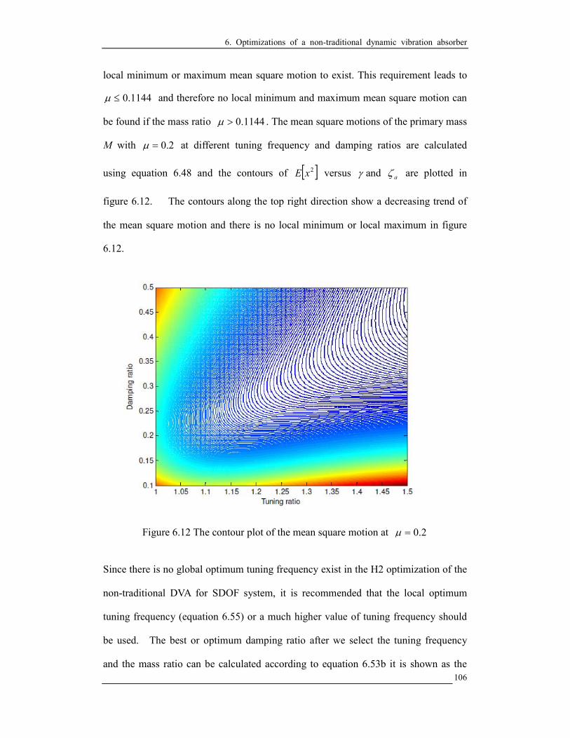
6. Optimizations of a non-traditional dynamic vibration absorber
106
local minimum or maximum mean square motion to exist. This requirement leads to
1144.0≤µ and therefore no local minimum and maximum mean square motion can
be found if the mass ratio 1144.0>µ . The mean square motions of the primary mass
M with 2.0=µ at different tuning frequency and damping ratios are calculated
using equation 6.48 and the contours of [ ]2xE versus γ and aζ are plotted in
figure 6.12. The contours along the top right direction show a decreasing trend of
the mean square motion and there is no local minimum or local maximum in figure
6.12.
Figure 6.12 The contour plot of the mean square motion at 2.0=µ
Since there is no global optimum tuning frequency exist in the H2 optimization of the
non-traditional DVA for SDOF system, it is recommended that the local optimum
tuning frequency (equation 6.55) or a much higher value of tuning frequency should
be used. The best or optimum damping ratio after we select the tuning frequency
and the mass ratio can be calculated according to equation 6.53b it is shown as the

6. Optimizations of a non-traditional dynamic vibration absorber
107
curve cutting across the contours of mean square motion in figure 6.13.
Figure 6.13 The contour plot of the mean square motion at 11.0=µ . (*) – local
minimum; (∆) – local maximum; (-) – optimum damping

6. Optimizations of a non-traditional dynamic vibration absorber
108
6.3 Summary
In this chapter, a non-traditional DVA is proposed and compared to the traditional
DVA for suppressing vibration of SDOF system. It has been proved analytically that
the performance of the non-traditional DVA is better than the traditional one. H∞ and
H2 optimizations of the non-traditional DVA are solved and tested for this DVA.
Relevant research reports found in literature are only about the H∞ optimization of this
DVA but they have only found the local optimum condition. As derived and proved
in the section 6.1, global optimum conditions of the DVA exist and the vibration
suppression performance of the DVA can be greatly improved if the global optimum
tuning is applied instead of the local optimum tuning. This new finding improves our
understanding of the dynamics of this DVA and it helps us to improve the vibration
suppression performance of this non-traditional DVA.
On the other hand, H2 optimization problem of this DVA has been solved analytically.
To the author’s knowledge, there is no research report found in literature on this topic.
As derived in section 6.2, local H2 optimum tuning condition of the DVA exists if
mass ratio is 0.1144 or less. No global optimum tuning condition exists if mass ratio
is higher than 0.1144 are found and it is recommended to use a high tuning frequency
ratio if possible. The best value of damping ratio after one select the tuning
frequency ratio is derived and stated in equation 6.53b.

7. Conclusions
109
7. CONCLUSIONS
Optimization theories of the traditional DVA applied suppressing vibrations in beam
and plate structures are established in chapters 4 and 5, respectively. The optimum
tuning conditions of the traditional DVA in beams and plates are proved to be very
similar. It is found that the optimum tunings including the tuning frequency and
damping ratios as well as the attachment location of the DVA in both the beam and
plate structures depend on the mass ratio and modal response at the attachment point
of the DVA. New and better results than those reported by other researchers (Dayou
2006, Jacquot 2001) have been found. These new results have been reported to and
published in an international journal.
In chapter 6, optimization theory of a non-traditional DVA for suppressing vibration
in a SDOF system is established. As shown in figure 6.3, the fixed-point theory is not
suitable to this new DVA because the response amplitudes at both fixed-points
decrease when the tuning ratio increases. Only the local optimum tuning condition of
this DVA can be found if one uses the standard fixed-points theory. On the other hand,
it has been found that global optimum tuning condition of the DVA exists and a new
theory has been established for finding this global optimum tuning condition of the
DVA. It is proved that the results reported by Ren (2001), and Liu and Liu (2005) are
based on the local optimum condition of this DVA and there are global optimum
conditions of the DVA that can produce much better vibration suppression of the
primary systems. Moreover, H2 optimization theory for this new DVA in reducing the
kinetic energy of the primary mass under white noise excitation is established. This
research provides results which are never found in the relevant literature. Some of the
results have been reported to and published in an international journal and some other

7. Conclusions
110
will be submitted for publication as well.
Future research can be focused on the new DVA applied to suppress vibrations in
MDOF or continuous systems under different types of excitations.

Appendices
111
APPENDIX A. EULER-BERNILLI BEAM WITH A FORCE
Consider figure A.1,
Figure A.1 Free body diagram of the beam element
Consider the free body diagram and applying Newton second law, we may write
2
2
t
wAdxFn ∂
∂=∑ ρ (A.1)
dxt
IM n 2
2
∂∂
=∑θ
ρ (A.2)
From equation A.1, we have
2
2
t
wAdxFdxdx
x
QQQ
∂∂
=+∂∂
−− ρ (A.3)
Fx
Q
t
wA =
∂∂
+∂∂
⇒2
2
ρ (A.4)
From equation A.2, we have
0=+∂∂
−− Qdxdxx
MMM (A.5)
Qx
M=
∂∂
⇒ (A.6)

Appendices
112
The bending moment is related to the curvature of the beam element by the flexure
equation written as
2
2
x
wEIM
∂∂
= (A.7)
Using equations A.6 and A.7, we may write
Qx
wEI
x=
∂∂
∂∂
)(2
2
(A.8)
3
3
x
wEIQ
∂∂
=⇒ (A.9)
Substitute equation A.9 into A.4, we have
Fx
wEI
t
wA =
∂∂
+∂∂
4
4
2
2
ρ (A.10)

Appendices
113
APPENDIX B. THE FORCE DUE TO DVA APPLIED ON THE
BEAM
Consider the figure A.2,
Figure A.2 Force due to DVA acting on the primary mass M
Considering force balance, we may write
)()( 112
2
xxcxxkt
xm && −−−−=
∂∂
(A.11)
and )()( 11 xxcxxkF && −−−−= (A.12)
Applying the Laplace transform into (A.11) and (A.12), we have
)()( 11
2
1 XXcsXXksmX −−−−= (A.13)
and )()( 11 XXcsXXkF −−−−= (A.14)
Using equations (A.13) and (A.14), we may write
kcsms
kcs
X
X
+++
=2
1 (A.15)
2
1 1
msF
X−= (A.16)
Multiplying equations (A.15) and (A.16), we have
( )X
kcsms
kcsmsF
+++
−=2
2
(A.17)

References
114
REFERENCES
1. Asami, T. and Nishihara, O., 2002, H2 Optimization of the Three-Element Type
Dynamic Vibration Absorbers, Journal of Vibration and Acoustics, 124, pp.
583-592.
2. Asami, T. and Nishihara, O., 2003, Closed-Form Exact Solution to H∞
Optimization of Dynamic Vibration Absorbers (Application to Different Transfer
Functions and Damping Systems), Journal of Vibration and Acoustics 125, pp.
398-405
3. Asami, T. and Nishihara, O., and Baz, A. M., 2002, Analytical Solutions to H
and H2 Optimization of Dynamic Vibration Absorbers Attached to Damped
Linear Systems, Journal of Vibration and Acoustics, 124, pp. 284-295.
4. Benaroya H. 2004, Mechanical Vibration Analysis, Uncertainties, and Control,
Marcel Dekker, Inc.
5. Brennan, M. J. and Dayou, J., 2000, Global control of vibration using a tunable
vibration neutralizer, Journal of Sound and Vibration, 232 (3), pp. 585-600.
6. Brock, J. E., 1946, A note on the Damped Vibration Absorber, ASME Journal of
Applied Mechanics, 13(4), pp. 284.
7. Cha, P. D. and Ren, G., 2006, Inverse problem of imposing nodes to suppress
vibration for a structure subjected to multiple harmonic excitations, Journal of
Sound and Vibration, 290 (1-2), pp. 425-447.
8. Cha, P. D. and Zhou, X., 2006, Imposing points of zero displacements and zero
slopes along any linear structure during harmonic excitations, Journal of Sound
and Vibration, 297 (1-2), pp. 55-71.
9. Cha, P. D., 2001, Alternative formulations to obtain the eigensolutions of a
continuous structure to which spring-mass systems are attached, Journal of
Sound and Vibration, 246 (4), pp. 741-750.
10. Cha, P. D., 2002, Specifying nodes at multiple locations for any normal mode of
a linear elastic structure, Journal of Sound and Vibration, 250 (5), pp. 923-934.
11. Cha, P. D., 2004, Imposing nodes at arbitrary locations for general elastic
structures during harmonic excitations, Journal of Sound and Vibration, 272
(3-5), pp. 853-868.
12. Cha, P. D., 2005, Enforcing nodes at required locations in a harmonically excited
structure using simple oscillators, Journal of Sound and Vibration, 279 (3-5), pp.

References
115
799-816.
13. Cha, P. D., 2007, Free vibration of a uniform beam with multiple elastically
mounted two-degree-of-freedom systems, Journal of Sound and Vibration, 307
(1-2), pp. 386-392.
14. Chan, K. T., Leung, T. P. and Wong, W. O., 1996, Free vibration of simply
supported beam partially loaded with distributed mass, Journal of Sound and
Vibration 191 (4), pp. 590-597
15. Chen. Y.D., Fuh, C.C., and Tung. P.C., 2005, Application of voice coil motors in
active dynamic vibration absorbers, IEEE Transactions on Magnetics 41 (3):
pp. 1149-1154.
16. Crandall, S. H., and Mark, W. D., 1963, Random Vibration in Mechanical
Systems, Academic Press.
17. Dayou, J. and Brennan, M. J., 2001, Global control of structural vibration using
multiple-tuned tunable vibration neutralizers, Journal of Sound and Vibration,
258 (2), pp. 345-357.
18. Dayou, J. and Kim, S. M., 2005, Control of kinetic energy of a one-dimensional
structure using multiple vibration neutralizers, Journal of Sound and Vibration,
281 (1-2), pp. 323-340.
19. Dayou, J., 2006, Fixed-points theory for global vibration control using vibration
neutralizer, Journal of Sound and Vibration, 292 (3-5), pp. 765-776.
20. Den Hartog J.P., Mechanical Vibrations, Dover Publications Inc., 1985.
21. Frahm, H., 1911, Device for Damping Vibrations of Bodies, U.S. Patent, No. 989,
958, 3576-3580.
22. Fuller C. R. and Silcox R. J., 1992, Active structural acoustic control, Journal of
Acoustical Society of America, 91, 519.
23. Fuller C. R., Maillard J. P., Mercadal M. and A. H. Von Flotow, 1995, Control of
aircraft interior noise using globally detuned vibration absorbers, Proceedings of
First CEAS/AIAA Aeroacoustics Conference, Munich, 615-624.
24. Gradshteyn, I. S. and Ryzhik, I. M., 1994, Table of Integrals, Series, and
Products, Academic Press, Inc.
25. Hadi, M. and Y. Arfiadi, 1998, Optimum design of absorber systems using modal
data, Journal of Structural Engineering, 124, pp. 1272-1280.
26. Hahnkamm, E., 1932, Die Dampfung von Fundamentschwingungen bei
veranderlicher Erregergrequenz, Ingenieur Archiv, pp. 192-201, (in German).
References
116
27. Hunt J.B., Dynamic vibration absorbers, Mechanical Engineering Publications
Ltd., 1979.
28. Jacquot, R. G., 1976, The response of a system when modified by the attachment
of an additional sub-system, Journal of Sound and Vibration, 60 (4), pp.
345-351.
29. Jacquot, R. G., 2000, Random vibration of damped modified beam systems,
Journal of Sound and Vibration, 234 (3), pp. 441-454.
30. Jacquot, R. G., 2001, Suppression of random vibration in plates using vibration
absorbers, Journal of Sound and Vibration, 248 (4), pp. 585-596.
31. Jacquot, R. G., 2003, The spatial average mean square motion as an objective
function for optimizing damping in damping in damped modified systems,
Journal of Sound and Vibration, 259 (4), pp. 955-956.
32. Jacquot, R. G., 2004, Optimal damper location for randomly forced cantilever
beams, Journal of Sound and Vibration, 269 (3-5), pp. 623-632.
33. Jalili, N. and Knowles, D.W., 2004, Structural vibration control using an active
resonator absorber: modeling and control implementation, Smart Materials and
Structures 13 (5): pp. 998-1005.
34. Karnovsky I. A., and Lebed O. L., 2001, Formulas for structural dynamics, table,
graphs and solutions, McGraw-Hill, New York.
35. Korenev B.G. and Reznikov L.M., Dynamic Vibration Absorbers, Theory and
Technical Applications, John Wiley & Sons, 1993.
36. Korenev, B. G. and L. M. Reznikov, 1993, Dynamic Vibration Absorbers: Theory
and Technical Applications, Wiley, New York.
37. Kreyszig, E., Advance Engineering Mathematics, Wiley, New York, 1993.
38. Lin J., 2005, An active vibration absorber of smart panel by using a decomposed
parallel fuzzy control structure, Engineering Applications of Artificial
Intelligence 18 (8): pp. 985-998.
39. Liu, K, and Liu, J., 2005, The damped dynamic vibration absorbers: revisited and
new result, Journal of Sound and Vibration, 284 (3-5), pp. 1181-1189.
40. Moyka, Ana S., Adaptive Vibration Absorber, Virginia Polytechnic Institute and
State University Thesis, 1996.
41. Nagya K. and Li. L 1997, Control of sound noise radiated from a plate using
dynamic absorber under the optimization by neural network, Journal of Sound
and Vibration, 208(2) 289-298.

References
117
42. Nishihara, O. and Matsuhisa, H., 1997, Design and Tuning of Vibration Control
Devices via Stability Criterion, Prepr. Of Jpn Soc. Mech. Eng., No. 97-10-1, pp.
165-168 (in Japanese)
43. Ormondroyd, J., and Den Hartog, J. P., 1928, The Theory of the Dynamic
Vibration Absorber, ASME Journal of Applied Mechanics, 50(7), pp. 9-22.
44. Ren, M. Z., 2001, A variant design of the dynamic vibration absorber, Journal of
Sound and Vibration, 245 (4), pp. 762-770.
45. Rice, H. J., 1993, Design of multiple vibration absorber systems using modal
data, Journal of Sound and Vibration, 160 (2), pp. 378-385.
46. Soedel, W., 1993, Vibrations of shells and plates, second edition, revised and
expanded, Marcel Dekker, Inc.
47. Strauss, W. A., Partial Differential Equations An Introduction, Wiley, New York,
1992.
48. Srinivasan P., Mechanical Vibration Analysis, McGraw Hill, New York, 1982.
49. Takita Y. and Seto K., 1989, An Investigation of adjustable pendulum-type
vibration controlling equipment (semi-active vibration control by application of
an anti-resonance point), American Society of Mechanical Engineers, Pressure
Vessels and Piping Division (Publication) PVP, American Soc of Mechanical
Engineers (ASME), New York, v179, 109-115.
50. Tang S. L., Suppression of Structural Vibration with a new type of vibration
absorber, MPhil Thesis, The Hong Kong Polytechnic University, 2005.
51. Tentor, L. B., Characterization of an electromagnetic tuned vibration absorber,
PhD Thesis, Virginia Polytechnic Institute and State University, 2001.
52. Thomson, W. T. and Dahleh, M. D., 1998, Theory of Vibration with Applications,
Prentice Hall
53. Warburton, G. V., 1980, Minimizing structural vibrations with absorbers,
Earthquake Engineering & Structural Dynamics, 8, pp. 197-217.
54. Warburton, G. V., 1981, Optimum absorber parameters for minimizing vibration
response, Earthquake Engineering & Structural Dynamics, 9, pp. 251-262.
55. Warburton, G. V., 1982, Optimum absorber parameters for various combinations
of response and excitation parameters, Earthquake Engineering & Structural
Dynamics, 10, No. 3, pp. 381-401.
56. Wong W.O., Tang S.L., Cheung Y.L. and Cheng L., Design of a dynamic
vibration absorber for vibration isolation of beams under distributed loading,

References
118
Journal of Sound and Vibration, 301, (2007) 898-908.
57. Wu, S. T., Chen, J. Y., Chiu, Yeh, Y. C. and Chiu, Y. Y., 2007b, An active
vibration absorber for a flexible plate boundary-controlled by a linear motor,
Journal of Sound and Vibration, 300 (1-2), pp. 250-264.
58. Wu, S. T., Chen, Y. J. and Shao, Y., 2007a, Adaptive vibration control using a
virtual-vibration-absorber control, Journal of Sound and Vibration, 305 (4-5), pp.
891-903.