optimization review jones road superfund site, harris …€¦ · · 2014-09-10optimization...
TRANSCRIPT

EPA 542-R-14-006 Office of Solid Waste and Emergency Response
Office of Superfund Remediation and Technology Innovation
Optimization Review Jones Road Superfund Site
Harris County, Texas
www.clu-in.org/optimization | www.epa.gov/superfund/cleanup/postconstruction/optimize.htm

EPA 542-R-14-006 Office of Solid Waste and Emergency Response
Office of Superfund Remediation and Technology Innovation
OPTIMIZATION REVIEW
JONES ROAD SUPERFUND SITE
HARRIS COUNTY, TEXAS
Report of the Optimization Review
Site Visit Conducted at the Jones Road Superfund Site
April 17, 2013
August 01, 2014
Revised 20 August 2014

Jones Road Superfund Site i Optimization Review Report Harris County, Texas
CONTENTS
Section Page
NOTICE ....................................................................................................................................................... iii
PREFACE .................................................................................................................................................... iv
ACRONYMS AND ABBREVIATIONS ..................................................................................................... v
EXECUTIVE SUMMARY .................................................................................................................... ES-1
1.0 OBJECTIVES OF OPTIMIZATION REVIEW .............................................................................. 1
2.0 OPTIMIZATION REVIEW TEAM ................................................................................................ 2
3.0 REMEDIAL ACTION OBJECTIVES AND SELECTED REMEDIES ......................................... 3
3.1 Remedial Action Objectives and Affected Media .............................................................. 3
3.2 Selected Remedies .............................................................................................................. 5
3.3 Potential Additional Remedies ........................................................................................... 6
4.0 FINDINGS ....................................................................................................................................... 7
4.1 Data Gaps and Characterization .......................................................................................... 7
4.2 Remedial Strategy ............................................................................................................... 8
5.0 RECOMMENDATIONS ............................................................................................................... 11
5.1 Recommendations for SVE Remedy in Unsaturated Chicot Sand ................................... 11
5.2 Recommendations for SVE for Shallow Soil Treatment .................................................. 12
5.3 Recommendations for ISB in Shallow WBZ .................................................................... 15
5.4 Recommendations for Lower Chicot WBZ ...................................................................... 17
5.5 Recommendations for Data Management and Communication ....................................... 19
5.6 Recommendations for Remedy Performance Monitoring ................................................ 20
5.7 Recommendations for Remedy Exit Criteria .................................................................... 21

Jones Road Superfund Site ii Optimization Review Report Harris County, Texas
TABLES
Table Page
1 Optimization Review Team ............................................................................................................. 2
2 Other Optimization Review Contributors ........................................................................................ 2
3 Contaminants of Concern and Cleanup Goals ................................................................................. 4
4 Affected or Potentially Affected Media on Site ............................................................................... 4
5 Remedial Action Objectives as Stated in the ROD .......................................................................... 5
6 Remedies Selected in the Record of Decision ................................................................................. 6
7 Identified Data Gaps ........................................................................................................................ 7
8 Recommendation Summary ........................................................................................................... 23
FIGURES
Figure Page
1 Site Location .................................................................................................................................... 1
2 Contaminant migration and potential exposure pathways at the Jones Road Site. (Diagram not to scale) ...................................................................................................................... 3
3 Cross-section of mass distribution in shallow source soil. Majority of site mass is located in Shallow Soil near and beneath shopping center. ............................................................................ 13
APPENDICES
A REFERENCES
B SUPPORTING FIGURES FROM EXISTING DOCUMENTS
C RECOMMENDED GROUNDWATER REMEDY PERFORMANCE MONITORING PROGRAM

Jones Road Superfund Site iii Optimization Review Report Harris County, Texas
NOTICE
Work described herein was performed by GSI Environmental Inc. (GSI) and Tetra Tech Inc. (Tetra Tech) for and with contributions from the U.S. Environmental Protection Agency. Work conducted by GSI was performed under Task Order 13-612/012 of EPA Contract EP-W-13-016. Work performed by Tetra Tech, including final production of this report, was performed under work assignment (WA) 2-58 of EPA Contract EP-W-07-078. Mention of trade names or commercial products does not constitute endorsement or recommendation for use.
This optimization review is an independent study funded by the EPA that focuses on protectiveness, cost-effectiveness, site closure, technical improvements, and green remediation. Detailed consideration of EPA policy was not part of the scope of work for this review. This report does not impose legally binding requirements, confer legal rights, impose legal obligations, implement any statutory or regulatory provisions, or change or substitute for any statutory or regulatory provisions. Mention of trade names or commercial products does not constitute endorsement or recommendation for use.
Recommendations are based on an independent evaluation of existing site information, represent the technical views of the optimization review team, and are intended to help the site team identify opportunities for improvements in the current site remediation strategy. These recommendations do not constitute requirements for future action; rather, they are provided for consideration by the EPA Region and other site stakeholders.
While certain recommendations may provide specific details to consider during implementation, these recommendations are not meant to supersede other, more comprehensive, planning documents such as work plans, sampling plans and quality assurance project plans (QAPP); nor are they intended to override applicable or relevant and appropriate requirements (ARARs). Further analysis of recommendations, including review of EPA policy, may be needed before they are implemented.

Jones Road Superfund Site iv Optimization Review Report Harris County, Texas
PREFACE
This report was prepared as part of a national strategy to expand Superfund optimization practices from site assessment to site completion implemented by the U.S. Environmental Protection Agency Office of Superfund Remediation and Technology Innovation (OSRTI). The project contacts are as follows:
Organization Key Contact Contact Information EPA Office of Superfund Remediation and Technology Innovation (OSRTI)
Kirby Biggs EPA OSRTI Technology Innovation and Field Services Division (TIFSD) 2777 Crystal Drive Arlington, VA 22202 [email protected] Phone: 703-823-3081
Environmental Management Support, Inc. (EMS)
Abraham Parker EMS 8601 Georgia Avenue Suite 500 Silver Spring, MD 20910 [email protected] Phone: 301-589-5318
GSI Environmental (Contractor to EMS)
Mindy Vanderford, PhD Mike Schofield
GSI Environmental, Inc. 2211 Norfolk Suite 1000 Houston, TX 77098 [email protected] Phone: 713-522-6300 x 186 [email protected] Phone: 713-522-6300
Tetra Tech (Contractor to EPA)
Jody Edwards, P.G. Tetra Tech, Inc. 45610 Woodland Road Suite 400 Sterling, VA 20166 [email protected] Phone: 802-288-9485
Doug Sutton, PhD, P.E. Tetra Tech, Inc. 2 Paragon Way Freehold, NJ 07728 [email protected] Phone: 732-409-0344

Jones Road Superfund Site v Optimization Review Report Harris County, Texas
ACRONYMS AND ABBREVIATIONS
3DVA Three-Dimensional Visualization and Analysis µg/L Micrograms per liter AI Air Injection bgs Below Ground Surface CERCLA Comprehensive Environmental Response, Compensation, and Liability Act COCs Contaminants of Concern CPT Cone Penetrometer Testing CSIA Compound-Specific Isotope Analysis CSM Conceptual Site Model cVOC Chlorinated Volatile Organic Compound cis-1,2-DCE cis-1,2-Dichloroethene DoD Department of Defense DPT Direct-Push Technology DQO Data Quality Objectives EA EA Engineering, Science and Technology, Inc. EPA U.S Environmental Protection Agency ESD Explanation of Significant Differences FS Feasibility Study GAC Granular Activated Carbon GC/MS Gas Chromatography/Mass Spectrometry GIS Geographic Information System Hapsite Hapsite Portable GC/MS Contaminant Identification System HQ Headquarters IC Institutional Control ISB In Situ Bioremediation MCL Maximum Contaminant Level NAPL Non-aqueous Phase Liquid ND Non-detect NPL National Priorities List O&M Operations and Maintenance ORP Oxidation/Reduction Potential OSRTI Office of Superfund Remediation and Technology Innovation PCE Tetrachloroethene (Perchloroetheylene) P&T Pump and Treat QAPP Quality Assurance Project Plan RAC Remedial Action Contractor RAO Remedial Action Objective RI Remedial Investigation ROD Record of Decision RPM Remedial Project Manager SVE Soil Vapor Extraction TCE Trichloroethene TCEQ Texas Commission on Environmental Quality trans-1,2 DCE trans-1,2-Dichloroethylene VC Vinyl Chloride

Jones Road Superfund Site vi Optimization Review Report Harris County, Texas
VI Vapor Intrusion VOC Volatile Organic Compound WBZ Water Bearing Zone

Jones Road Superfund Site ES-1 Optimization Review Report Harris County, Texas
EXECUTIVE SUMMARY
Optimization Background
The U.S. Environmental Protection Agency defines optimization as the following:
“Efforts at any phase of the removal or remedial response to identify and implement specific actions that improve the effectiveness and cost-efficiency of that phase. Such actions may also improve the remedy’s protectiveness and long-term implementation which may facilitate progress towards site completion. To identify these opportunities, regions may use a systematic site review by a team of independent technical experts, apply techniques or principles from Green Remediation or Triad, or apply other approaches to identify opportunities for greater efficiency and effectiveness. Contractors, states, tribes, the public, and PRPs are also encouraged to put forth opportunities for the Agency to consider.” (1)
An optimization review considers the goals of the remedy, available site data, conceptual site model (CSM), remedy performance, protectiveness, cost-effectiveness and closure strategy. A strong interest in sustainability has also developed in the private sector and within federal, state and municipal governments. Consistent with this interest, optimization now routinely considers green remediation and environmental footprint reduction during optimization reviews.
An optimization review includes reviewing site documents, interviewing site stakeholders, potentially visiting the site for 1 day and compiling a report that includes recommendations in the following categories:
• Protectiveness • Cost-effectiveness • Technical improvement • Site closure • Environmental footprint reduction.
The recommendations are intended to help the site team identify opportunities for improvements in these areas. In many cases, further analysis of a recommendation, beyond that provided in this report, may be needed before the recommendation can be implemented. Note that the recommendations are based on an independent review and represent the opinions of the optimization review team. These recommendations do not constitute requirements for future action, but rather are provided for consideration by the State of Texas, the Region and other site stakeholders. Also note that while the recommendations may provide some details to consider during implementation, the recommendations are not meant to replace other, more comprehensive, planning documents such as work plans, sampling plans and quality assurance project plans (QAPP).
1 U.S. Environmental Protection Agency (EPA). 2012. Memorandum: Transmittal of the National Strategy to Expand
Superfund Optimization Practices from Site Assessment to Site Completion. From: James. E. Woolford, Director Office of Superfund Remediation and Technology Innovation. To: Superfund National Policy Managers (Regions 1 – 10). Office of Solid Waste and Emergency Response (OSWER) 9200.3-75. September 28.

Jones Road Superfund Site ES-2 Optimization Review Report Harris County, Texas
Site-Specific Background
The Jones Road Ground Water Plume Superfund Site is located in western Harris County, Texas, just outside of the city limits of Houston, Texas, in EPA Region 6. The site is the location of the former Bell Dry Cleaners. The dry cleaning facility operated between 1988 and 2002 in a small shopping center in an area of mixed commercial and residential land use. Releases of chlorinated volatile organic compounds (cVOC) from improper disposal of dry cleaning solvents migrated vertically downward through the unsaturated zone to perched water and to lower aquifers, where multiple private water supply wells were and are presently located.
Land use surrounding the site was primarily agricultural prior to rapid suburban development in the 1960s and 1970s. As part of the suburban and commercial development, many private water supply wells were installed in the area. Tetrachloroethene (PCE) contamination was discovered in an area private water supply well in 2000. Subsequent investigations identified leakage from dry cleaning operations at Bell Dry Cleaners as the most likely source.
The site was added to the National Priorities List (NPL) on September 29, 2003, and remedial investigation (RI) activities under the Comprehensive Environmental Response, Compensation, and Liability Act (CERCLA) have been on-going since this time. The RI and feasibility study (FS) reports were finalized in 2009, and a Record of Decision (ROD) was published in September 2010. The remedy selected in the ROD includes an extensive groundwater extraction and treatment system (pump and treat – P&T). Subsequent site data collection and cost estimates indicate that the selected remedy may not provide an optimal approach to address site contamination. Remedial activities implemented since NPL listing have focused on eliminating human exposure through the water ingestion pathway. Remedies to date include extending municipal water supplies to properties with affected private water supply wells. Approximately 51 percent of well owners chose to connect to municipal supplies. The site is currently in the remedial design phase to address contamination in soil and groundwater.
Summary of Conceptual Site Model and Key Findings
Shallow surface soil below the shopping center is composed of dense clay, extending to a depth of approximately 25 feet below ground surface (bgs). Area aquifers include the Chicot (ground surface to approximately 400 feet bgs) and the Evangeline (below 400 feet bgs). A shallow, perched water-bearing zone (Shallow WBZ) is located below the clay unit in the upper Chicot aquifer, with a saturated thickness of 10 feet or less. Underlying the Shallow WBZ is an unsaturated clay (35 to 60 feet bgs) and an unsaturated sand (60 to 110 feet bgs) (Unsaturated Chicot). The Lower Chicot aquifer is encountered at a depth below 110 feet bgs and extends to a depth of approximately 400 feet bgs.
Based on contaminant concentration data and preliminary mass distribution estimates, the Shallow Soil (0 to 25 feet bgs) in the source area contains the majority of the site contaminant mass (estimated at 54 percent in the FS). Contaminant mass is concentrated in the area immediately under and behind the former dry cleaners. The Shallow WBZ (25 to 35 feet bgs) is a thin, sandy, silty layer that may be discontinuous in the region. The highest concentrations in the Shallow WBZ appear to be in the area of monitoring well MW-01. However, it is unclear whether the full extent of Shallow WBZ contamination has been delineated down- and cross-gradient.
The potential exists for vapor intrusion (VI) into indoor air in the commercial property because of the high cVOC concentrations in the Shallow Soil and Shallow WBZ. While some preliminary vapor assessments have been performed, the magnitude of VI impacts has not been fully characterized.
During the RI phase, an unsaturated zone in the Chicot unit (Unsaturated Chicot) was not fully identified. From approximately 60 feet bgs to saturation at 110 feet bgs is a fine, unsaturated sand with relatively

Jones Road Superfund Site ES-3 Optimization Review Report Harris County, Texas
high vapor phase concentrations of PCE. The unsaturated zone has been identified by Region 6 as a potentially important treatment area to cut off the transport of mass from the shallow source area to the Lower Chicot WBZ.
The Shallow Soil, Shallow WBZ and the Unsaturated Chicot in the immediate area of the shopping center east and just west of Jones Road contain the majority of contaminant mass. The optimization review team has identified these media as priorities for remedial response based on the potential for continued contribution of contamination to lower strata.
The primary remedy selected in the ROD is an extensive P&T system, which, in terms of mass removed per dollar spent, does not appear to be highly effective or implementable. An in-situ bioremediation (ISB) remedy using reducing amendments was selected for the Shallow WBZ in the ROD. A soil vapor extraction remedy (SVE) has been proposed by both the EPA Region 6 Remedial Project Manager (RPM) and the site optimization team to address contamination in the Unsaturated Chicot, which was not directly addressed in the ROD. Uncertainties related to the selected ISB remedy include choosing an appropriate amendment for the ISB and determining if metals such as arsenic and manganese may be mobilized as a result of the changes in the oxidation/reduction potential (ORP). The primary uncertainty relating to the SVE proposed for the Unsaturated Chicot is the efficacy of mass removal and the magnitude of long-term releases of contaminants from the unsaturated clay layer.
The optimization review team finds that the Shallow Soil, the location of the majority of residual contaminant mass, should be addressed by an aggressive remedy. Uncertainties and complications that may influence the design of the Shallow Soil remedy include the density of the clay and the infrastructure present on site. While excavation and thermal treatment may be appropriate for affected clay, the presence and continued use of the building currently preclude these options. SVE is a possible alternative remedy in the Shallow Soil, but questions remain about its efficacy in the dense clay.
The groundwater P&T remedy selected for the affected Shallow WBZ and Lower Chicot WBZ was intended to address both hydraulic control and treatment. Historical evidence on P&T systems indicate that these remedies are better suited to hydraulic control as they seldom achieve full treatment, so there is some uncertainty about the ability of the selected remedy to attain cleanup goals. As noted above, the extent of the plume in the Shallow WBZ may not be fully delineated. Additionally, groundwater flow direction in the Lower Chicot WBZ can be and has been variable, depending on area pumping regimes. Uncertainty about the direction of groundwater flow and the magnitude of groundwater withdrawal from various depths confounds predictions about plume migration, and ultimately, about the risk of exposure and the success of the remedy. As noted above, the cost of the remedy as selected relative to its ability to attain remedial goals is in question. Because of the uncertainty about the hydrogeology of the Lower Chicot WBZ, it is unclear if the extent of the plume has been fully delineated. Long-term management and remediation of the Lower Chicot WBZ plume may require an optimized approach to P&T, aggressive reduction of mass flux from the source, and additional monitoring locations.
The optimization review team finds that data gaps described above should be addressed for optimal design of P&T systems for both the Shallow WBZ and Lower Chicot.
The optimization review team further finds that continued outreach to the community is appropriate because of the continued possibility of human exposure to contaminants.
Data collection for the site has been ongoing since the mid- to late 1990s by multiple contractors and regulatory entities. Much of the historical data have not been transferred to an electronic format suitable for current data interpretation and visualization software. Integration of the full historical dataset into the CSM is recommended because of the complexity of site hydrostratigraphy.

Jones Road Superfund Site ES-4 Optimization Review Report Harris County, Texas
Summary of Recommendations
A phased remedial approach is recommended for the site. The optimization review team recommends the site remedial design include aggressive source treatment, which is anticipated to reduce volatile organic compound (VOC) discharge to the Lower Chicot WBZ, supporting aquifer restoration in the lower plume. Elements and priorities for the phased approach include:
• Install an SVE system in the Unsaturated Chicot sand unit (60 to 110 feet bgs). A ROD amendment is anticipated to initiate the process.
• Delineate the extent of groundwater contamination in the Shallow WBZ. Evaluate whether more extensive Shallow WBZ plume control is required.
• Perform an SVE pilot for the Shallow Soil and, if successful, install a full SVE system in the Shallow Soil to address the primary source of contaminant mass.
• Develop a VI indoor air sampling protocol, considering some of the evolving protocols discussed in Section 5.2.2. Sample indoor air before the SVE is installed as a baseline and, again, after soil treatment to demonstrate conditions are protective for the indoor air exposure pathway.
• Initiate ISB in high-concentration areas of Shallow WBZ; monitor groundwater concentration for cVOCs and metals. Calculate mass flux response to remedy.
• Measure groundwater levels and collect and analyze samples to determine contaminant concentrations in the Lower Chicot WBZ before source area remedies are installed to establish a current baseline. Monitor response of contaminant concentrations in existing Lower Chicot WBZ wells (as well as the Shallow WBZ wells) after the SVE system and ISB remedy are installed in the Upper Chicot.
• A limited groundwater P&T system is recommended for the Lower Chicot and possibly the Shallow WBZ near the source area (just east of Jones Road) to control plume migration. The P&T system should be installed after SVE and ISB remedies in the source area, and after a period of time sufficient to evaluate their efficacy. If the source treatments are effective at reducing mass flux to the Lower Chicot and there are no identified secondary sources (for example, non-aqueous phase liquid [NAPL]) in the Lower Chicot, the P&T system may be limited in scope or eliminated.
• Install extraction wells in the Shallow WBZ as a contingent remedy if SVE and ISB remedies do not perform as anticipated or if more extensive shallow zone plume control is required. Groundwater extracted from the Shallow WBZ can be treated with the P&T system, if required, in the Lower Chicot WBZ.
• No additional remedies are recommended at this time for the unsaturated clay underlying the Shallow WBZ. The strength of the Unsaturated Chicot clay as a long-term source of contaminants to the Lower Chicot will be determined by groundwater monitoring. A remedial approach may be devised in the future to address clay as a secondary source.

Jones Road Superfund Site ES-5 Optimization Review Report Harris County, Texas
• Area residents with private water supply wells in the Lower Chicot have been provided the opportunity to connect to municipal water supplies. However, several members of the community have opted not to connect to municipal water or have chosen to maintain their private wells as a source of irrigation water. Outreach efforts are recommended to educate potentially affected residents about the opportunities and rationale to connect to municipal water. Additionally, efforts should be made to ensure that parties intending to purchase properties with affected water supply wells are fully informed of the status of the groundwater supply.
• There are several data gaps in the CSM for the Lower Chicot aquifer. Groundwater flow direction and the effects of hydrostratigraphic heterogeneity on the flow regime are not well characterized. The extent of contamination in the Lower Chicot is not well understood. However, the optimization review team believes that characterizing and remediating media in the immediate vicinity of the former dry cleaners (for example, the Shallow Soil, Shallow WBZ and Unsaturated Chicot) should be the top priority of the site team. Additional characterization of deeper groundwater should be considered after remedial components have been installed in areas of highest residual contaminant mass. Future Lower Chicot aquifer characterization may include installation of additional nested wells, optimally placed to assess groundwater flow direction and contamination at various depths (for example, 150 to 200 feet bgs, 200 to 250 feet bgs, and 250 to 300 feet bgs).
• Develop and continue to support electronic data management and visualization tools to document and communicate remedy performance more rapidly and effectively. Consider performing 3-dimensional visualization and analysis (3DVA) to support interpretation and future monitoring of plume distribution and dynamics, particularly in the Lower Chicot aquifer.

Jones Road Superfund Site 1 Optimization Review Report Harris County, Texas
1.0 OBJECTIVES OF OPTIMIZATION REVIEW
The Jones Road Ground Water Plume Superfund Site is located in western Harris County, Texas, just outside of the city limits of Houston, Texas, in EPA Region 6 (See Figure 1). The Jones Road Site was added to the National Priorities List (NPL) September 29, 2003, and remedial investigation (RI) activities under the Comprehensive Environmental Response, Compensation, and Liability Act (CERCLA) have been on-going since this time. The RI and feasibility study (FS) reports were finalized in 2009 (Shaw 2009a, 2009b) and a Record of Decision (ROD) was published in September 2010 (EPA 2010). The site is currently in the remedial design phase.
For more than a decade, the U.S. Environmental Protection Agency Office of Superfund Remediation and Technology Innovation (OSRTI) has provided technical support to the EPA regional offices through the use of independent (third-party) optimization reviews at Superfund sites. The Jones Road Site was nominated for an optimization review at the request of the Region 6 Remedial Project Manager (RPM) in January 2013. The current review of the remedy design proposed for Jones Road is intended to optimize the remedial response to address contamination in soil and groundwater to achieve maximum protectiveness while improving cost and energy efficiency and minimizing time required to attain cleanup goals.
To this end, an optimization review team (described below) was assembled and met with regulatory stakeholders and consultants in Dallas, Texas, and at the site near Houston, Texas, in April 2013 to review site data, remediation goals, potential funding, and time frames to implement the remedy. This report is a summary of the recommendations of the optimization review team based on a review of site documents, the site visit, and meeting with stakeholders.
Objectives of the remedial design optimization review include:
• Review of conceptual site model (CSM) • Review of Remedial Action Objectives (RAO) • Review of selected remedies, anticipated additional actions, and associated costs • Provide recommendations for remedial strategy, including:
o Addressing and prioritizing significant data gaps in the CSM o Recommending remedy improvements, including new remedy components o Prioritization and sequencing of remedial components o Identifying decision points for contingent responses o Performance monitoring for recommended remedies o Remediation and data collection to support an Exit Strategy
Figure 1: Site Location
Excerpt from Figures 1 and 2 of the September 2010 ROD. Full size versions of these figures are provided in Appendix B.

Jones Road Superfund Site 2 Optimization Review Report Harris County, Texas
2.0 OPTIMIZATION REVIEW TEAM
The optimization review team consisted of the independent, third-party participants listed below who collaborated with representatives of EPA Headquarters (HQ) and EPA Region 6, the Texas Commission on Environmental Quality (TCEQ), and representatives of EA Engineering, Science and Technology, Inc. (EA), the Remedial Action Contractor (RAC) for EPA.
The independent (third-party) optimization review team consisted of the following individuals:
Table 1: Optimization Review Team Name Organization Phone Email
Mindy Vanderford GSI Environmental Inc. 713-522-6300 [email protected]
Mike Schofield GSI Environmental Inc. 713-522-6300 [email protected]
Doug Sutton Tetra Tech Inc. 732-409-0344 [email protected]
The following individuals contributed to the optimization review process:
Table 2: Other Optimization Review Contributors
Name Organization Title/Party Present for Site Visit/Site Meeting
Kirby Biggs EPA HQ Optimization Review Lead Site Meeting
Tom Kady EPA HQ ERT Optimization Review Team Site Meeting
Camille Hueni EPA Region 6 RPM Site Visit/Site Meeting
Vincent Mallot EPA Region 6 Region 6 Optimization Liaison Site Meeting
Marilyn Czimer Long TCEQ Project Manager Site Meeting
Buddy Henderson TCEQ Project Technical Support Site Meeting
Ted Telisak EA RAC Project Manager Site Meeting
Jay Snyder EA RAC Consultant Site Meeting
A site visit was conducted by Camille Hueni from Region 6 and Mindy Vanderford and Mike Schofield of GSI on April 17, 2013, in Harris County, Texas. A follow-up meeting with all of the participants listed above was held at Region 6 Headquarters in Dallas, Texas, on April 23, 2013. Documents reviewed during the optimization review process are listed in Appendix A.
This optimization review utilized existing environmental data to interpret the CSM, evaluate remedy performance and make recommendations to improve the remedy. The quality of the existing data was evaluated by the optimization review team before the data were used for these purposes. The evaluation for data quality included a brief review of how the data were collected and managed (where practical, the site quality assurance project plan [QAPP] is considered), the consistency of the data with other site data, and the use of the data in the optimization review. Data that were of suspect quality were either not used as part of the optimization evaluation or were used with the quality concerns noted. Where appropriate, this report provides recommendations made to improve data quality.
Jones Road Superfund Site 3 Optimization Review Report Harris County, Texas
3.0 REMEDIAL ACTION OBJECTIVES AND SELECTED REMEDIES
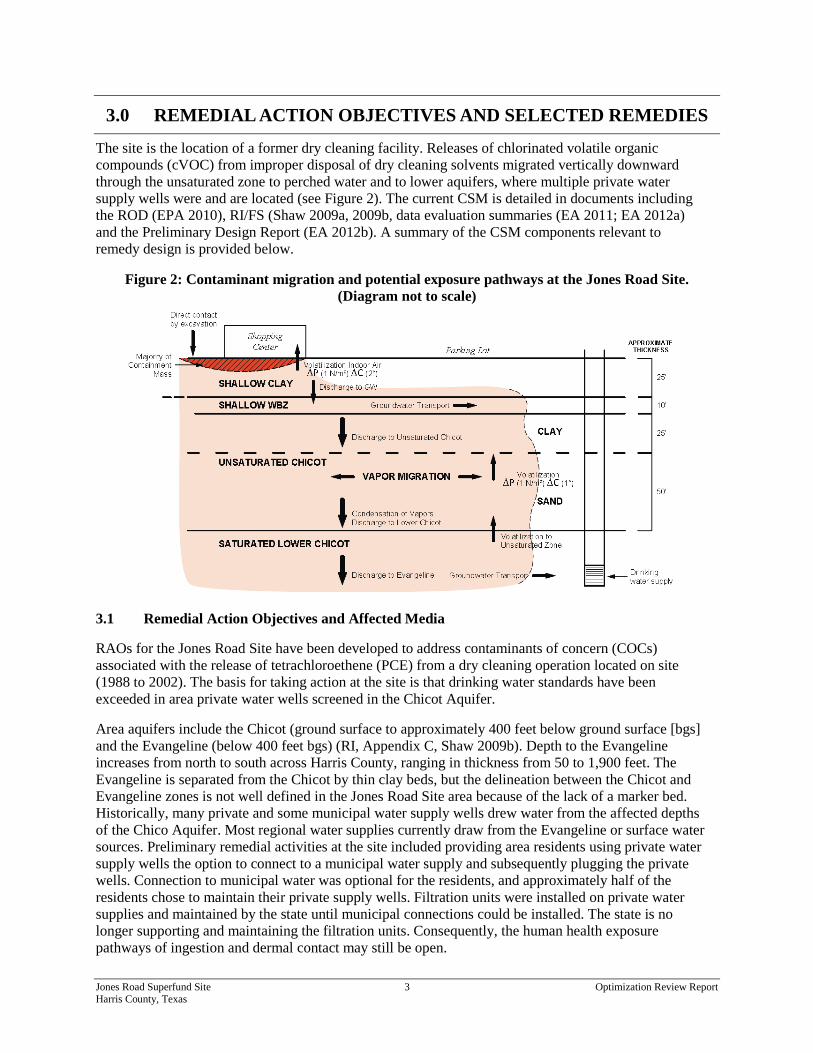
The site is the location of a former dry cleaning facility. Releases of chlorinated volatile organic compounds (cVOC) from improper disposal of dry cleaning solvents migrated vertically downward through the unsaturated zone to perched water and to lower aquifers, where multiple private water supply wells were and are located (see Figure 2). The current CSM is detailed in documents including the ROD (EPA 2010), RI/FS (Shaw 2009a, 2009b, data evaluation summaries (EA 2011; EA 2012a) and the Preliminary Design Report (EA 2012b). A summary of the CSM components relevant to remedy design is provided below.
Figure 2: Contaminant migration and potential exposure pathways at the Jones Road Site. (Diagram not to scale)
3.1 Remedial Action Objectives and Affected Media
RAOs for the Jones Road Site have been developed to address contaminants of concern (COCs) associated with the release of tetrachloroethene (PCE) from a dry cleaning operation located on site (1988 to 2002). The basis for taking action at the site is that drinking water standards have been exceeded in area private water wells screened in the Chicot Aquifer.
Area aquifers include the Chicot (ground surface to approximately 400 feet below ground surface [bgs] and the Evangeline (below 400 feet bgs) (RI, Appendix C, Shaw 2009b). Depth to the Evangeline increases from north to south across Harris County, ranging in thickness from 50 to 1,900 feet. The Evangeline is separated from the Chicot by thin clay beds, but the delineation between the Chicot and Evangeline zones is not well defined in the Jones Road Site area because of the lack of a marker bed. Historically, many private and some municipal water supply wells drew water from the affected depths of the Chico Aquifer. Most regional water supplies currently draw from the Evangeline or surface water sources. Preliminary remedial activities at the site included providing area residents using private water supply wells the option to connect to a municipal water supply and subsequently plugging the private wells. Connection to municipal water was optional for the residents, and approximately half of the residents chose to maintain their private supply wells. Filtration units were installed on private water supplies and maintained by the state until municipal connections could be installed. The state is no longer supporting and maintaining the filtration units. Consequently, the human health exposure pathways of ingestion and dermal contact may still be open.

Jones Road Superfund Site 4 Optimization Review Report Harris County, Texas
No contamination has been detected in groundwater samples collected from the Lower Chicot/Evangeline Aquifer interface (MW-17) to date (2008 most recent sample). At this time, no information is available that suggests that the Evangeline aquifer is affected. An affected shallow perched water-bearing zone is located approximately 25 to 35 feet bgs in the Upper Chicot Formation. The perched saturated unit will be called the Shallow Chicot Water-Bearing Zone (WBZ) in this report. The Shallow Chicot WBZ is not a current drinking water supply. The primary remedial concern for this perched unit is that it may be an ongoing source of contamination to the underlying Lower Chicot WBZ, a historical source of drinking and irrigation water classified as a potential drinking water source by the state (Class I, water). Currently, area municipal water supply wells are screened in the deeper Evangeline unit.
Site COCs and cleanup levels based on federal Maximum Contaminant Levels (MCLs) are shown in Table 3. Affected and potentially affected media along with potential exposure and migration pathways are summarized in Table 4 and depicted above in Figure 2. Table 5 lists RAOs for the source area and downgradient groundwater.
Table 3: Contaminants of Concern and Cleanup Goals Constituent Name Affected Media Cleanup Goal
Tetrachloroethene (PCE)
Shallow and Lower Chicot WBZ
5 µg/L
Trichloroethene (TCE) 5 µg/L
cis-1,2-Dichlroethylene (cis-1,2 DCE) 70 µg/L
trans-1,2-Dichloroethylene (trans-1,2 DCE) 100 µg/L
Vinyl chloride (VC) 2 µg/L µg/L = micrograms per liter
Table 4: Affected or Potentially Affected Media on Site
Medium Location Composition Potential Exposure / Migration Pathways
Shallow Soil (Clay) Ground surface to 25 feet bgs
Dense clay to silty clay • Discharge to underlying shallow groundwater (WBZ)
• Direct exposure by excavation
Shallow Chicot Water-Bearing Zone (WBZ)
25 to 35 feet bgs Saturated fine to silty sand – perched and likely discontinuous
• Not a drinking water supply
• Discharge downgradient and to the underlying Lower Chicot
• Direct exposure by excavation
Unsaturated Chicot 35 to 60 feet bgs 60 to 110 feet bgs
Clay to silty clay (35 to 60 feet bgs); sand (60 to 110 feet bgs)
• Vapor phase discharge to underlying Lower Chicot aquifer

Jones Road Superfund Site 5 Optimization Review Report Harris County, Texas
Medium Location Composition Potential Exposure / Migration Pathways
Saturated Lower Chicot WBZ
60 to 400 feet bgs Fine sand to well-graded sand, occasional clay lenses
• Private drinking water supply
• Discharge to deeper Evangeline aquifer – primary public water supply
Indoor air Commercial retail building
Slab on grade • Inhalation risk- volatilization from shallow clay
bgs = below ground surface
Table 5: Remedial Action Objectives as Stated in the ROD Site Area Remedial Action Objective
Source Area
Prevent future human exposure to contaminated groundwater at unacceptable risk levels Prevent or minimize further migration of contaminants from source materials to groundwater (source control) Prevent or minimize further migration of the contaminant plume (plume containment) Return groundwater to its expected beneficial uses whenever practicable (aquifer restoration)
Deep Groundwater Plume
Prevent future human exposure to contaminated groundwater at unacceptable risk levels Prevent or minimize further migration of the contaminant plume (plume containment) Return groundwater to its expected beneficial uses whenever practicable (aquifer restoration)
3.2 Selected Remedies
The remedy described in the ROD for the site includes a combination of groundwater extraction and treatment (pump and treat – P&T) and in situ enhancements to stimulate contaminant mass destruction in the source area (in situ bioremediation [ISB]) (see Table 6). The selected remedy also included institutional controls (IC) for groundwater and indoor air sampling for vapor intrusion (VI) evaluation, plugging water wells and supplying water service to properties with private groundwater wells screened in the Lower Chicot WBZ.
In the ROD, the choice of in situ amendments included plans for a treatability study to evaluate the most effective in situ treatment for the location and soil type. A pilot ISB injection test was conducted in June 2012 (EA 2013a). Groundwater P&T from both the Shallow WBZ and the Lower Chicot WBZ would address the RAO of containing the plumes and preventing further migration. The P&T remedy is anticipated to include air stripping and vapor granular activated carbon (GAC) treatment before water is reinjected to prevent issues with subsidence in the area.

Jones Road Superfund Site 6 Optimization Review Report Harris County, Texas
Table 6: Remedies Selected in the Record of Decision
Remedy Target Medium Description Hydraulic Containment / Pump and Treat
Shallow WBZ source area and Lower Chicot WBZ
Pump groundwater (800 gallons per minute) from both the shallow and deeper subsurface at a rate to prevent further migration of contaminants – estimated 420 million gallons per year
• Eight extraction wells • Two treatment compounds • GAC vessels/air stripper • 12 injection wells • Pre- and post-treatment for scale, pH and
fouling (*Description from Remedial Design Report)
In Situ Treatment Shallow soil and groundwater
Treatment of soil and groundwater with amendments that manipulate oxidation/reduction environment in situ – amendments to be chosen based on treatability studies
Plugging water supply wells and water supply connections
Lower Chicot WBZ Plug residential and commercial water wells penetrating the Chicot Aquifer for locations where a water line has been supplied
ICs Commercial property, affected groundwater
Restrict excavation or drilling into affected subsurface areas
Groundwater monitoring Shallow WBZ and Lower Chicot WBZ
Collection of contaminant concentration data to assess remedy performance, progress toward remedial goals and protectiveness
Indoor air investigation Air inside commercial building
Sample air inside the commercial building under varying weather conditions to assess the VI exposure pathway
Five-Year Reviews All site media Reports to document remedy performance and protectiveness
3.3 Potential Additional Remedies
During the RI phase, an unsaturated zone in the Lower Chicot was not fully identified. Therefore, the presence of a potential vapor phase was not considered as a source in the evaluation of remedial options or in the selection of a remedy in the ROD. Figure 2 illustrates the current understanding of the strata underlying the site. At the start of the optimization review, a modification of the ROD was already anticipated by Region 6 RPMs to include a soil vapor extraction (SVE) system to address the confirmed contamination in this zone. A pilot SVE test in the Unsaturated Chicot Sand was conducted in January 2013 (EA 2013b).

Jones Road Superfund Site 7 Optimization Review Report Harris County, Texas
4.0 FINDINGS
This section outlines the major findings of the optimization review team.
4.1 Data Gaps and Characterization
During the site meeting and document review, several key data gaps and uncertainties in the Jones Road Site CSM were identified. Perceived data gaps and a data quality objective (DQO) review of existing data are discussed in detail in the Data Evaluation Summary Report (EA 2012a). Table 7 prioritizes data gaps identified that may reduce the efficiency of remedial actions.
Table 7: Identified Data Gaps
Medium Data Gap Recommendation
Shallow WBZ Extent of contamination in Shallow WBZ
Delineate down- and cross-gradient extent of contamination (proposed sampling locations are detailed in Section 4.2).
Shallow WBZ In Situ Bioremediation (ISB) effects
Implement remedy, but monitor groundwater for build-up of degradation products and mobilization of metals.
Indoor air commercial building
Indoor air as a potentially complete exposure pathway
Sample indoor air using passive sampler.
Unsaturated Lower Chicot
Extent of contamination Delineate horizontal extent of affected zone.
Lower Chicot WBZ
Groundwater flow direction at various depths, delineation of contaminant
Monitor groundwater elevations and concentrations at existing wells. Additional characterization may be pursued after aggressive source treatment.
All lithologic strata
Continuity and connectivity of stratigraphic layers
Develop highly detailed boring logs for new monitoring wells and remedial components. Develop a comprehensive site database and geographic information system (GIS) incorporating new site data and historic data to the extent possible. Consider use of 3- dimensional visualization and analysis (3DVA) methods and tools going forward.
Affected groundwater in the Shallow WBZ is not delineated. The down- and cross-gradient extent of contamination, particularly in the area of well MW-6, is not known. Lack of delineation in this zone hinders estimation of total contaminant mass, area of affected media, and likelihood of mass migration to other media. Similarly, the extent of contamination in the Unsaturated Lower Chicot Sand and Clay is unknown. Estimates of total contaminant mass and affected area are required for both pre- and post-remediation conditions to assess the efficacy of remedial efforts.
Groundwater flow direction in the Lower Chicot WBZ can be and has been variable, depending on area pumping regimes. Uncertainty about the direction of groundwater flow and the magnitude of groundwater withdrawal from various depths can confound predictions about plume migration.

Jones Road Superfund Site 8 Optimization Review Report Harris County, Texas
Questions remain for the ISB remedy selected for the Shallow WBZ as to whether amendments will result in complete dehalogenation and whether reducing conditions will mobilize metals such as manganese and arsenic from the subsurface. An additional concern is that vinyl chloride (VC) generated as a result of biodegradation will present an excess risk to indoor air.
4.2 Remedial Strategy
The following CSM elements were found to be relevant to designing an optimal remedial approach.
• Based on concentration data and preliminary mass distribution estimates (Shaw 2009a), the Shallow Soil (0 to 25 feet bgs) in the source area contains the majority of site contaminant mass (estimated 54 percent in the FS). Passive soil gas sampling results indicate that the majority of contaminant mass is in the shallow subsurface immediately behind and beneath the former Bell Cleaners building (see Figure 3). Sorbed mass can act as a long-term source to the dissolved phase plume. Remedies to address sorbed mass in the source will, therefore, produce the greatest long-term benefit to site cleanup.
• The Unsaturated portion of the Chicot between approximately 35 and 60 feet bgs consists of clay/silty clay similar to the Shallow Soil. However, from approximately 60 feet bgs to saturation at 110 feet bgs is a fine, unsaturated sand with relatively high vapor phase concentrations (130,000 micrograms per cubic meter PCE at SVE-2). The unsaturated zone has been identified by Region 6 RPMs as a potentially important treatment area to cut off the transport of mass from the shallow source area to the Lower Chicot WBZ.
• The Shallow WBZ (25 to 35 feet bgs) is a thin, sandy, silty layer that may be discontinuous in the region. Groundwater in this zone shows the highest concentrations in the area of MW-01, OB-01 and OB-02 downgradient to MW-06, where the plume appears to end abruptly or turns to the east. The highest concentrations in the Shallow WBZ appear to be near monitoring well MW-01. It is unclear whether the full extent of Shallow WBZ contamination has been delineated. Uncertainties about contaminant mass transport in this zone may affect assessments of mass discharge to lower strata.
A phased remedial approach is recommended for the Jones Road Site. Optimization review team recommendations for the site remedial design include aggressive source treatment, which is anticipated to reduce VOC discharge to the Lower Chicot WBZ, supporting aquifer restoration in the lower plume.
Remedial priorities and decision points are summarized here and described in detail in Section 5.
• Install an SVE system in the Unsaturated Chicot sand unit (60 to 110 feet bgs). A ROD amendment is anticipated to initiate the process. (An Explanation of Significant Differences (ESD) or other ROD amendment is anticipated to select SVE as a remedy. Additional remedy optimization recommendations may be included in the ESD at the discretion of Region 6 project managers.)
• Delineate the extent of groundwater contamination in the Shallow WBZ. Evaluate whether more extensive shallow zone plume control is required.
• Pilot test an SVE system in the Shallow Soil to address the primary source of contaminant mass. If the pilot test is successful at removing contaminant mass, implement a full-scale SVE in the Shallow Soil. While an SVE system for the Shallow Soil will most likely require a separate skid and blower, some integration with the anticipated SVE system for the lower Unsaturated Chicot Sand may result in cost savings.

Jones Road Superfund Site 9 Optimization Review Report Harris County, Texas
• Develop a VI sampling protocol to address indoor air inside the shopping center, considering some of the evolving protocols discussed in Section 5.2.2. Sample indoor air before SVE is installed and after soil treatment to demonstrate conditions are protective for the indoor air exposure pathway.
• Initiate ISB in high-concentration areas of Shallow WBZ; monitor groundwater concentration for VOCs and metals and calculating mass flux response to remedy.
• Measure groundwater levels and collect and analyze samples to determine contaminant concentrations in the Lower Chicot WBZ before source area remedies are installed to establish a current baseline. Monitor response of contaminant concentrations in existing Lower Chicot WBZ wells (as well as the Shallow WBZ wells) after the SVE system and ISB remedy have been installed in the upper Chicot.
• A limited groundwater P&T system is recommended for the Lower Chicot and possibly the Shallow WBZ near the source area (just east of Jones Road) to control plume migration. The P&T system should be installed after SVE and ISB remedies in the source area and after a period of time sufficient to evaluate their efficacy. If the source treatments are effective at reducing mass flux to the Lower Chicot and there are no identified secondary sources (for example, non-aqueous phase liquid [NAPL]) in the Lower Chicot, the P&T system may be limited in scope or eliminated.
• Install extraction wells for a P&T system in the Shallow WBZ as a contingent remedy if SVE and ISB remedies do not perform as anticipated or if more extensive shallow zone plume control is required. Groundwater extracted from the Shallow WBZ can be treated with the P&T system, if required, in the Lower Chicot WBZ.
• No additional remedies are recommended, at this time, for the unsaturated clay underlying the Shallow WBZ. The strength of the Unsaturated Chicot clay as a long-term source of contaminants to the Lower Chicot will be determined by groundwater monitoring. A remedial approach to address secondary sources in the clay may be devised in the future. Groundwater monitoring data will provide information on how to design and scale the remedy, if needed.
• Area residents with private water supply wells in the Lower Chicot have been provided the opportunity to connect to municipal water supplies. However, several members of the community have opted not to connect to municipal water or have chosen to maintain their private wells as a source of irrigation water. Outreach efforts are recommended to educate potentially affected residents about the opportunities and rationale to connect to municipal water. Additionally, efforts should be made to ensure that parties intending to purchase properties with affected water supply wells are fully informed of the status of the groundwater supply.
• There are several data gaps in the CSM for the Lower Chicot aquifer. Groundwater flow direction and the effects of hydrostratigraphic heterogeneity on the flow regime are not well characterized. The extent of contamination in the Lower Chicot is not well understood. However, the optimization review team believes that characterizing and remediating media in the immediate vicinity of the former dry cleaners (for example, the Shallow Soil, Shallow WBZ and Unsaturated Chicot) should be the top priority of the site team. Additional characterization of deeper groundwater should be considered after remedial components have been installed in areas of highest residual contaminant mass. Future Lower Chicot aquifer characterization may include installation of additional nested wells, optimally placed, to assess groundwater flow direction and contamination at various depths (for example 150 to 200 feet bgs, 200 to 250 feet bgs, and 250 to 300 feet bgs). Installation of monitoring wells will address data site characterization and data

Jones Road Superfund Site 10 Optimization Review Report Harris County, Texas
gaps while providing long-term monitoring locations for remedy performance assessment, plume stability evaluations and demonstrations of protectiveness.
• Develop and continue to support electronic data management and visualization tools to document and communicate remedy performance more rapidly and effectively. Consider performing 3-dimensional visualization and analysis (3DVA) to support interpretation and future monitoring of plume distribution and dynamics, particularly in the Lower Chicot aquifer.
Remedies common to all of the strata, both source and plume areas, include ICs, groundwater monitoring, and preparation of Five-Year Reviews. These remedial components should be instituted as described in the ROD.

Jones Road Superfund Site 11 Optimization Review Report Harris County, Texas
5.0 RECOMMENDATIONS
The recommendations provided by the optimization review team address the data gaps identified in Section 4.1 and are consistent with the remedial strategy outlined in Section 4.2. The presentation of the recommendations is consistent with the remedy prioritization and sequencing presented in Section 4.2. Additional recommendations are provided for performance monitoring, data management and development of exit criteria for each remedy component.
Relative to the ROD, the recommended strategy raises the priority of source remediation and emphasizes performance monitoring and timely shutdown of remedy components. Collectively, the recommendations help fill critical data gaps and satisfy the RAOs.
The primary “source” area refers to the immediate vicinity of the former Bell Dry Cleaners, including the shopping center, alley, and parking area. The known affected source media include the Shallow Soil, Shallow WBZ, Unsaturated Chicot, Sand and Clay and Lower Chicot WBZ east of Jones Road, and the secondary source area refers to matrices slowly releasing contaminants immediately under and west of Jones Road.
5.1 Recommendations for SVE Remedy in Unsaturated Chicot Sand
An SVE system is recommended to remove contamination in situ in the Unsaturated Chicot Sand (60 to 110 feet bgs). An SVE system has already been evaluated by EPA Region 6 RPMs, and the optimization review team agrees this approach is appropriate and should be prioritized. An SVE pilot test was performed in this zone in January 2013. Results of the pilot test indicate the approach is appropriate and effective for this zone (EA 2013b).
Treatment for the Unsaturated Chicot Sand was not listed in the ROD and will most likely require a ROD amendment. Delineation of contamination in this zone will support evaluations of remedy performance for this area and will provide a better estimate of total contaminant mass that may be discharging to the lower saturated zone.
The clay interval, located 30 to 60 feet bgs, presents several remedial challenges. Because of the density of infrastructure in the area and on-going use of the shopping center, thermal treatment and excavation are not currently recommended. Treatment of the Shallow WBZ with ISB and treatment of the underlying sandy layer of the unsaturated zone may reduce flux of contaminants to the Lower Chicot WBZ, but the clay layer is anticipated to remain a long-term, low-level source of contamination. Long-term groundwater monitoring of the Lower Chicot WBZ will provide data on the effect of vapor phase back-diffusion from the Unsaturated Chicot clay and will help prioritize and scale potential future remedial responses. Thermal treatment or excavation should be considered if the shopping center property is demolished or redeveloped.
Recommendation 5.1.1: The optimization review team agrees that installation of an SVE system in the Unsaturated Chicot Sand is a priority. Five SVE wells (SVE-01 – 05) and one deeper well (IW-01D) are currently in place east of Jones Road under the immediate source area. The SVE treatment system can be installed on property behind the shopping center, owned by the current shopping center owner.
Benefits of Implementing Section 5.1 Recommendations
• Reduce or eliminate mass discharge from source to Lower Chicot Aquifer.
• Reduce or eliminate need for extensive P&T in Lower Chicot WBZ.
• Reduce uncertainty about the location and extent of contaminant mass in the Unsaturated Chicot Sand.

Jones Road Superfund Site 12 Optimization Review Report Harris County, Texas
Recommendation 5.1.2: In addition to the six SVE wells east of Jones Road, two to three vapor and groundwater monitoring wells should be installed to a depth of approximately 130 feet bgs with screened intervals from 90 to 130 feet bgs into the saturated zone (similar in construction to existing SVE-4; see field boring log in Appendix B Figures) west of Jones Road. The unsaturated sand is present from approximately 60 to 110 feet bgs, with the saturated Lower Chicot present below approximately 110 feet bgs and unsaturated clay present above 60 feet bgs. The wells will be used to help delineate the extent of contamination in the Unsaturated Chicot Sand and monitor remedy performance.
Locations of the new vapor and groundwater wells may be contingent on property access agreements with landowners. (Note: if wells are installed through a contaminated zone of the Shallow Chicot WBZ plume, the wells should be double cased to prevent vertical migration of COCs.) Preliminary suggestions for the well locations include one well west of Jones Road near existing well MW-9. A second potential location is west of Jones Road directly across from Barley Lane. A third location may be chosen based on access and sampling results from the two other wells.
The primary remedial risk for SVE in the Unsaturated Chicot Sand is insufficient air supply in the Lower Chicot. Insufficient air supply will be indicated by low recovery and development of vacuum conditions. The likelihood of this remedial risk is low because of the depth and porosity of the sand zone. An additional potential complication with SVE in this zone is re-saturation of this unit. Saturation of the Unsaturated Chicot Sand could occur over a period of years with high precipitation or changes in recharge caused by land redevelopment. Re-saturation is, however, not anticipated from current discharge levels from the Shallow WBZ.
A preliminary cost estimate for installation of SVE in the Unsaturated Chicot Sand is $150,000 for three new wells, and design and construction of connecting piping, a blower skid (estimate 7.5 horsepower) with moisture separator, and GAC treatment and controls in a fenced compound. Annual operating and maintenance, including monthly system checks, quarterly sampling and analysis, GAC change-outs, power and annual reporting, would be approximately $40,000.
5.2 Recommendations for SVE for Shallow Soil Treatment
SVE is recommended for the shallow clay soil in the area immediately behind and beneath the shopping center, focusing on the area around the SVE-01. Although the Shallow Soil has fairly low permeability, SVE may be a viable remedy in the limited area of highest contaminant mass (see Figure 3). Based on the continued use of the shopping center and the limited access to the area of high contamination (in an alley behind the shopping center and below the building), excavation or thermal treatment are not practical. SVE may not fully remediate contamination in this zone, but would serve to address an area of highest residual contaminant mass and, therefore, limit migration to the Shallow WBZ, indoor air and deeper strata.
An SVE system is anticipated by both the site and optimization review teams for the Unsaturated Chicot Sand (60 to 110 feet bgs). (Note: the Unsaturated Chicot Clay layer [30 to 60 feet bgs] is not recommended for SVE.) Extending the SVE system to the Shallow Soil in the area of highest contaminant mass, or installing a separate system with a higher vacuum blower, if necessary, is technically straightforward and can be accomplished at low cost. SVE is anticipated to address the potential VI exposure pathway for the commercial buildings and capture some contamination that would otherwise migrate vertically and laterally across the site. Shallow Soil SVE and Shallow WBZ ISB treatment, along
Benefits of Implementing Section 5.2 Recommendations
• Focus remedy on area of highest contaminant mass.
• Reduce discharge of mass from shallow soil to groundwater.
• Address concerns about vapor intrusion into existing building.

Jones Road Superfund Site 13 Optimization Review Report Harris County, Texas
with SVE in the Unsaturated Chicot Sand, are anticipated to cut off the majority of mass contributions from the source area to the Lower Chicot WBZ. An ESD or other ROD amendment is anticipated prior to implementation of the SVE system.
Recommendation 5.2.1: Pilot test an SVE system in the Shallow Soil source area in the vicinity of SVE-01, behind the shopping center, near former boring GP-04. An illustration of the zone of high contaminant mass to be targeted by the Shallow Soil SVE is provided in Figure 3. If the pilot test demonstrates that an SVE system can effectively remove contaminant mass, design and install a Shallow Soil SVE system to address contamination in the Shallow Soil.
Figure 3: Cross-section of mass distribution in shallow source soil. Majority of site mass is located in Shallow Soil near and beneath shopping center.
The additional system is anticipated to include four to five new SVE wells installed to a depth of approximately 30 to 35 feet bgs, screened from the surface to 25 feet bgs in the alley behind the shopping center, between existing wells MW-02 and MW-03. An air injection (AI) process is anticipated to be part of the design, but precise design specifications will be developed by Region 6 and the Response Action Contractor (RAC). SVE may have a limited area of influence in the clay of the Shallow Soil; therefore, SVE wells may be placed more densely here than in more permeable strata. Remedy performance will be measured by contaminant mass removal in the vapor effluent.
Assuming a separate blower skid will be needed, the optimization review team estimates that installation of up to five shallow SVE wells and associated piping to convey extracted vapors to the separate SVE treatment system will cost approximately $90,000 to $130,000. This cost would be in addition to the costs for the Unsaturated Chicot Sand system and includes collocation and integration of controls. The additional operations and maintenance (O&M) cost would be approximately $50,000 to $70,000 per year,

Jones Road Superfund Site 14 Optimization Review Report Harris County, Texas
depending on the power and equipment costs required to remove contaminants from the clay. More accurate cost and performance estimates for the full-scale remedy can be refined after an initial pilot test is performed. The overall capital cost could be reduced by approximately $40,000 and the O&M cost reduced by approximately $10,000 per year if a common blower and treatment units could be used. The cost of the pilot is estimated to be $30,000, including a week of tests and multiple vapor sample analyses. Although the SVE system in the surficial clay unit may cost more and have a larger carbon footprint than SVE in more porous soils, other remedy options are limited by the presence of the building and infrastructure at the site.
Recommendation 5.2.2: VI is a potential exposure pathway at the Jones Road Site. Assessing the indoor air exposure pathway for affected sites is an evolving practice from both technical and regulatory perspectives. In addition to the 2002 EPA VI guidance (EPA 2002 #27), EPA is updating draft guidelines for VI assessments (www.epa.gov/oswer/vaporintrusion). State guidance on VI varies widely (Eklund 2012 #26), with 42 states issuing draft or final guidance as of 2012. State guidance varies on the number of times buildings must be tested as well as on the test methods and remedial approaches. The State of Texas does not have VI guidance at this time. Additional complicating factors in VI assessment include changes in screening levels.
Recent experimental results in animal tests have implicated trichloroethene (TCE) as a reproductive toxicant, initiating a reduction in the protective exposure levels for indoor air. Finally, new technologies in data collection, interpretation and management for VI investigations as well as remedial approaches for affected buildings contribute to the evolving landscape for VI. As approaches to VI are changing rapidly, the optimization review team recommends the following decision logic for addressing this exposure pathway.
1. Compare groundwater concentrations with EPA-published screening criteria for VI assessment (EPA 2002). As affected groundwater is shallow at the site and concentrations are high, the Jones Road Site will likely require VI assessment.
2. Utilize distance-based screening criteria to identify potential buildings for VI assessment. Typically, a 100-foot buffer around the groundwater plume is used for non-hydrocarbon VOCs.
3. Determine the investigation approach: VI investigation using vacuum SUMMA canisters with sample collection rate regulators is a widely accepted approach to sampling sub-slab vapor and indoor air. These samples provide a grab or time-weighted average exposure value. Investigations using SUMMA canisters normally include collecting one to three sub-slab samples per building (typically about one sample per 1,000 square feet), conducted before or along with indoor air sampling and a background outdoor air sample. One drawback of indoor air sampling with SUMMA canisters is that it does not distinguish between existing indoor and sub-slab vapor sources. An additional concern is that VI can vary with time either seasonally or as a result of other site conditions (for example, by building pressurization, where negative pressures can enhance intrusion).
4. Determine if alternative approaches are applicable. For example, recent VI investigation methods using a Hapsite Contaminant Identification System (Hapsite) instrument have been developed by Department of Defense (DoD) stakeholders and approved by state regulators (McHugh, Beckley et al. 2012) (GSI 2013 #28). The Hapsite instrument is a portable gas chromatograph/mass spectrometer (GC/MS) that provides direct, real-time data and precise locations of sources of contamination. The Hapsite can positively identify multiple cVOC constituents (including PCE, TCE and benzene) in real time and distinguish between indoor and VI sources. This feature would be beneficial in distinguishing possible sources related to the hair and nail salon operations in the shopping center and the automotive center operations next door from contamination that

Jones Road Superfund Site 15 Optimization Review Report Harris County, Texas
originates in the subsurface. The Hapsite protocol includes pressure regulation within the building to demonstrate cVOC concentrations under various pressurization scenarios to test the building’s susceptibility to VI. Data can be collected to target lines of evidence supporting regulatory decision making.
5. Passive diffusion samplers can be used as a low-cost, preliminary screening tool to prioritize and screen buildings or areas for more intensive investigations.
6. If indoor air is found to be affected above protective levels, several mitigation measures may be implemented. The Shallow Soil SVE system may be modified to provide depressurization (vacuum) on the soil vapor beneath the building along with sealing any slab penetrations or defects. Heating, ventilation, and air conditioning systems may be modified. Choice of appropriate mitigation is contingent on commercial activity, maintenance and property owner considerations. Decision documents may need to be modified (through a ROD amendment or Explanation of Significant Differences [ESD]) if an indoor air remedy is determined to be necessary.
The cost of VI investigations would vary depending on the number of mobilizations, the number and size of buildings investigated, and any complications arising from indoor and other sources. A preliminary estimate of $30,000 is provided for planning purposes. This cost would cover installation of up to 12 sub-slab vapor monitoring points and up to 30 vapor samples (sub-slab and indoor air) with analysis for VOCs over two mobilizations including a brief work plan and report.
Recommendation 5.2.3: An additional and contingent Shallow Soil remedy should include excavation of affected soil or thermal treatment. This remedy is recommended for consideration if the shopping center is to be demolished or redeveloped. While extensive site redevelopment is not anticipated in the near future, the option should be discussed if site redevelopment is pending.
5.3 Recommendations for ISB in Shallow WBZ
ISB treatment is the selected remedy for the higher concentration Shallow WBZ area near the former dry cleaners. The optimization team believes this is an appropriate remedy for the Shallow WBZ. A pilot test was conducted to evaluate the efficacy of ISB in June 2012 (EA 2013a). Overall, the results showed significant decreases in dissolved VOC concentrations; however, follow-up sampling was limited to a 6-month time frame after amendment, so the dataset on potential concentration rebound is limited.
Data gaps associated with this remedy include uncertainty associated with mobilization of metals such as manganese and arsenic and the extent of dechlorination to non-toxic end products. An additional concern is that VC generated as a result of biodegradation will present an excess inhalation risk.
Benefits of Implementing Section 5.3 Recommendations
• In situ destruction of contaminant mass in the Shallow WBZ.
• Limit migration of Shallow WBZ plume and limit potential vertical migration of contaminants.
• ISB remedy has limited infrastructure requirements and can be optimized around amendment composition and injection schedule.
• A potential concern with ISB is concentration rebound, given the high concentration of COCs in the shallow source clays. Long-term performance monitoring is recommended.

Jones Road Superfund Site 16 Optimization Review Report Harris County, Texas
Recommendation 5.3.1: Delineate the horizontal extent and continuity of contamination in the Shallow WBZ. Delineation of contamination in this zone is recommended prior to initiation of ISB injections. A combination of direct-push technology (DPT) sample delineation and installation of approximately three new monitoring wells in the Shallow WBZ is recommended.
Depending on the sampling results at these locations, other sampling locations may be recommended to complete delineation. Delineation may be performed using direct-push methods, but additional monitoring wells are recommended for on-going remedy performance monitoring, plume stability analysis and demonstrations of protectiveness. Detailed boring logs at sample locations will help address uncertainty about the extent and connectivity of lithologic layers.
• New monitoring well # 1 – cross-gradient to the east of centerline of plume, approximately 100 feet east and 50 feet north of MW-06. Direct-push methods can be used to identify the edge of groundwater exceeding the MCLs and to select a precise location for a groundwater new monitoring well. Samples at the new location should show low to non-detect levels of VOCs. The new location should be sampled annually to biennially going forward to confirm delineation of the plume. If samples show detections of cVOCs above MCLs, additional cross-gradient wells may be necessary to delineate the extent of the plume. For locations above MCLs, sample wells semi-annually to annually during active remediation to assess the efficacy of the remedy. Sample annually to biennially after active remediation to assess long-term aquifer restoration.
• New monitoring well # 2 – cross and downgradient east of MW-06, approximately 100 feet east and 25 to 50 feet south of MW-06 in the grassy easement. This location is intended to help delineate the downgradient edge of the plume to the southeast. The sampling frequency recommendation is as above.
• New monitoring well # 3 – cross and downgradient to the west of MW-06. Jones Road presents a significant impediment to delineating the western edge of the Shallow plume. The new well should be located across Jones Road, approximately parallel with the well recommended in the bullet above and the well recommended for the Lower Chicot to monitor SVE performance. The sampling frequency recommendation is also as above.
• When measurement of groundwater levels in the monitoring wells has established groundwater elevations in the area, complete delineation in the Shallow WBZ using direct-push methods and high-resolution site characterization approaches.
The optimization review team estimates that delineation efforts in the Shallow WBZ should cost approximately $30,000, depending on the number of DPT borings. The cost includes approximately $10,000 for the three wells, $10,000 for 2 days of DPT boring installation, about 20 total samples with VOC analysis, a brief work plan and report.
Recommendation 5.3.2: The optimization review team recommends that ISB treatments proceed after delineation of the plume in the Shallow WBZ. Amendments should be injected in the general vicinity of the pilot test. Delineation and monitoring efforts under Recommendation 5.3.1 will provide data to estimate the full footprint, total dissolved mass and center of mass of the Shallow WBZ plume. If plume delineation efforts indicate that the Shallow WBZ plume is significantly more extensive or mobile than indicated in the RI/FS, selection and installation of the P&T remedy described in Recommendation 5.3.3 may be considered.

Jones Road Superfund Site 17 Optimization Review Report Harris County, Texas
Groundwater monitoring should be conducted on a quarterly to semi-annual basis at wells with detectable concentrations after initiation of ISB to evaluate the performance of the remedy as well as formation of degradation products and potential mobilization of metals in groundwater. Specific recommendations for groundwater remedy performance monitoring are provided in Appendix C. Monitoring should continue at least annually after the injection period to detect potential rebound of contaminants.
The optimization review team agrees with the site team that the initial injection for the ISB remedy can be implemented with DPT injections based on the expected ease of implementation. Assuming the target treatment zone is limited to a 100-foot by 200-foot area with 10 feet of saturated thickness, the remedy might cost $500,000 for 66,000 pounds of emulsified vegetable oil diluted by more than 150,000 gallons of potable water and approximately 30 days of two DPT rigs and crews to conduct the injections.
Recommendation 5.3.3: If ISB does not meet performance goals or if degradation products or metals present excess risk, a Shallow WBZ P&T system is recommended be considered as a contingent remedy. A P&T system has been proposed for the Lower Chicot WBZ (see Recommendation 5.4.2). The optimization review team recommends that if the P&T system is installed in the Lower Chicot WBZ, the system can be extended to the Shallow WBZ for long-term control of plume migration. The decision to install a P&T system in the Shallow WBZ or continue with ISB injections could be based on the performance of the ISB and the cost comparison of long-term treatment of the Shallow WBZ with each technology. Treatment of the Shallow WBZ with P&T will be favorable if continued ISB will require frequent injections or if ISB results in unacceptable impacts to water quality. Additionally, P&T would be favorable for the Shallow WBZ if a Lower Chicot P&T system is installed and operating because the cost of adding shallow extraction wells to an already existing system is relatively inexpensive.
5.4 Recommendations for Lower Chicot WBZ
The Lower Chicot WBZ is considered to be the depth between 110 feet bgs and approximately 400 feet bgs. Below the initial source area (shopping center), groundwater in the Lower Chicot shows dissolved concentrations of PCE in the range of 200 micrograms per liter (µg/L). The combination of source removal and treatments (SVE, ISB and, potentially, source P&T) is anticipated to address the majority of contaminant mass discharge and promote aquifer restoration in the Lower Chicot WBZ.
The remedy recommended for the Lower Chicot WBZ is groundwater P&T, similar to that described in the ROD but limited to the area east of Jones Road beneath the source. The primary purpose of P&T in this zone is to control migration of contamination, preventing mass from the source in the upper strata and the plume in the Lower Chicot from discharging to potential drinking water supplies downgradient. The P&T remedy should be designed and installed after the SVE and ISB remedies have been installed. The remedial approach for the Lower Chicot WBZ is to eliminate mass discharge from the source area and measure responses in the Lower Chicot WBZ to “right size” the long-term response to contamination in this area. If groundwater concentrations in the Lower Chicot WBZ decrease in response to aggressive source area treatment in the upper zones, the P&T remedy can be scaled appropriately to address a much smaller plume footprint.
The area of the Lower Chicot plume downgradient from the source area is recommended for groundwater monitoring from existing wells for a period of 5 years after the SVE/ISB remedies have been installed to assess the efficacy of the source remedy.
Benefits of Implementing Section 5.4 Recommendations
• Reduced cost and footprint relative to the remedy selected in the ROD.

Jones Road Superfund Site 18 Optimization Review Report Harris County, Texas
After source removal efforts have been evaluated, additional characterization of the Lower Chicot may be considered.
Recommendation 5.4.1: Monitor groundwater in the Lower Chicot WBZ at existing wells and new wells recommended in Section 5.1.1 just west of Jones Road. A preliminary sampling event may be required in the near term to establish baseline conditions prior to aggressive source area treatment. A comprehensive sampling event prior to design of remedies (and preparation of the ROD amendment) will indicate changes in plume morphology since the last sampling event (2008) and will guide design of the remedial performance monitoring systems. After the SVE/ISB remedies have been installed in the source area, the Lower Chicot WBZ should be carefully evaluated to assess plume response. If concentrations in the Lower Chicot WBZ show statistically decreasing trends in the 3 years after SVE/ISB systems are installed in the source, then reconsider or postpone installation of the P&T system. (Note: decision documents may require amendment if the P&T remedy in the Lower Chicot WBZ is eliminated or altered significantly.)
Comprehensive sampling of the Lower Chicot WBZ prior to source remedy design is anticipated to cost approximately $20,000, depending on the number and availability of remaining private water supply wells. This cost assumes up to 20 wells sampled in a 1-week period by a two-person team with analysis of samples for cVOCs.
Recommendation 5.4.2: If Lower Chicot WBZ concentrations do not respond with stable to decreasing statistical trends to source treatment, a limited P&T system is recommended for the Lower Chicot WBZ in the area east of Jones Road. The treatment system should be designed to intercept the highest concentration groundwater under the shopping center and Jones Road.
If groundwater data from the Lower Chicot WBZ indicate plume expansion (either vertically or laterally) above MCLs, a more aggressive P&T system is recommended to control plume spread. Design of the P&T remedy for the Lower Chicot WBZ is, therefore, contingent on the response to aggressive source removal/treatment.
Risks to the P&T remedy performance include low mass removal and failure to control plume migration. A cost-benefit analysis should be performed for the P&T system during the Five-Year Review. The analysis should include estimates of the amount of mass removed relative to the cost of operating the remedy. Monitoring delineation wells for detections of cVOCs and assessing individual well trends and the distribution of plume mass will indicate plume migration. In the case of plume migration, a contingent remedy may include changing the pumping regime or location of extraction wells.
Recommendation 5.4.3: A comprehensive monitoring and data analysis program along with supplied municipal water and ICs is recommended for the downgradient plume in the Lower Chicot WBZ in the medium term. The monitoring program will include annual sampling of existing wells installed in the Lower Chicot WBZ, along with groundwater elevation measurements (at locations where possible) to assess the overall plume attenuation rate. Groundwater data should be evaluated for statistical concentration trends and estimates of total plume mass and center of mass over time. These analyses will provide a measure of the stability of the plume. Additional geochemical analyses may provide improved attenuation rates for contaminant mass in the Lower Chicot.
• Continue monitoring elevation of groundwater in the Lower Chicot WBZ west of Jones Road. Gaging water levels at private water wells may not be possible because of well construction and pumping issues. The recommendation is to measure elevations before private supply wells are plugged. Elevation may also be measured during pumping well maintenance such as replacement of pumps. Monitor changes in elevation as private pumping wells are removed from service and as the aquifer responds to changes in recharge caused by urbanization and climate variability.

Jones Road Superfund Site 19 Optimization Review Report Harris County, Texas
• Protectiveness of the aggressive source remedy should be evaluated during the Five-Year Review process. If contaminant concentrations in Lower Chicot groundwater increase or there is evidence of plume migration, a contingent remedy may include installation of the more extensive P&T system described in the preliminary remedial design document (EA 2012b).
• An additional consideration for documenting the rate of natural attenuation in the Lower Chicot WBZ may include Compound-Specific Isotope Analysis (CSIA) of dissolved cVOCs. CSIA evaluates the relative abundance of the heavy to light isotope ratios of carbon, chlorine or hydrogen in specific cVOCs. Compounds that have been biodegraded tend to show higher ratios of the heavier isotopes. CSIA has been used to provide evidence of contaminant destruction by anaerobic microbial degradation. Efforts are currently under way to develop models, guidelines and case studies for applying CSIA to demonstrate aerobic contaminant destruction through cometabolism. CSIA may be considered at some point in the future for the Jones Road Site to support development of appropriate degradation rates for the aerobic Lower Chicot groundwater. At present, CSIA methods may not be fully developed and broadly accepted, but the optimization review team believes that these tools may become more widespread in the next 5 years.
• Area residents with private water supply wells in the Lower Chicot WBZ have been provided the opportunity to connect to municipal water supplies. Several members of the community have opted not to connect to municipal water or have chosen to maintain their private wells as a source of irrigation water. Outreach efforts are recommended to educate potentially affected residents and potential buyers of property about the opportunities and rationale to connect to municipal water. If possible, there should be another round of connecting residents to municipal water supplies and plugging private water wells. The optimization review team recommends development of a fact sheet or webpage or holding a public meeting to motivate area residents to connect to the municipal supply.
• The Lower Chicot WBZ may require more extensive data collection and interpretation to support future evaluations of progress toward remedial goals. As stated above, the focus of recommendations in this report is to prioritize source treatment in the near term (the next 5 to 10 years) and evaluate the effect of source treatment in the downgradient Lower Chicot WBZ. Future tasks related to the Lower Chicot WBZ might include monitoring program optimization (to determine optimal placement of additional wells) and numerical modeling or 3DVA to track and predict the plume morphology and progress toward remedial goals.
The optimization review team has not provided cost estimates for the staged approach to the Lower Chicot WBZ, but believes that the reductions in the extraction system and treatment system relative to what was described in the ROD will likely save more than $1 million in capital costs.
5.5 Recommendations for Data Management and Communication
Data collection has been on-going at the Jones Road Site since the late 1990s, prior to widespread introduction of computational tools to manage and evaluate environmental data. The Jones Road Site extends over 350 acres and is difficult to visualize without an integrated GIS. Simple, but high–quality, data management systems are required to store and retrieve data for concentration trend assessment, mass quantification and mass flux assessments. Conversion of historical site sampling data to database format will help address outstanding data gaps.
Benefits of Implementing Section 5.5 Recommendations
• Streamlined data management and electronic visualization tools communicate remedy performance more rapidly and effectively.
• Electronic data management facilitates more sophisticated statistical and performance assessment methods.

Jones Road Superfund Site 20 Optimization Review Report Harris County, Texas
Recommendation 5.5.1: Several data management sub-tasks are recommended to improve archiving, analysis, organization and communication of site data:
• Creation of a site database containing sample identity, type and location information (sampling location name; X, Y and Z coordinates; sample medium; types of samples collected; analyses performed, and location of data results), analytical data (sample dates, analytes, concentration results, detection limits, and data flags), and lithologic data (boring logs, cone penetrometer testing [CPT] results, depth of observation, and type of geology). The database should prioritize data collected during the remedial design and installation phase, but should include, to the extent possible, data collected during the RI/FS stage, including CPT and DPT data, soil sample results, and private water supply well locations and data. Some location coordinates may need to be estimated from historical maps. Estimated data may be qualified in the site database to distinguish them from more quantitatively determined data.
• Creation of a GIS with all sampling locations (to the extent possible) and property ownership boundaries, major roads, infrastructure, easements and municipal water supply wells.
• Update the GIS with remedial components as they are installed. Update the site database with sample results as they are confirmed to meet DQOs.
• Produce maps and graphics with water wells and plume boundaries without the prominent residential property boundaries to clarify the distribution of mass relative to the source.
• Produce more detailed cross-sections including shallow zone lithologic details to the extent possible.
• Develop a data management and communication plan for stakeholders to support project and site decision-making.
Recommendation 5.5.2: Consider performing 3DVA of the site, specifically the Lower Chicot aquifer. The visualization can be performed using a variety of software tools, and the quality of the visualization will improve as data gaps are addressed. The use of 3DVA would support an integrated analysis of plume morphology and behavior as related to site geology and groundwater flow directions. 3DVA can also function as a remediation performance monitoring tool to support decisions on design of the future P&T or demonstrations of natural attenuation.
The cost of the initial 3DVA effort is anticipated to be in the range of $25,000 to $30,000, depending on data quantity and organization. The cost of each subsequent groundwater monitoring update would be on the order of $5,000.
5.6 Recommendations for Remedy Performance Monitoring
Performance monitoring recommendations for each of the remedies are described along with the remedies above. Details of groundwater remedy performance monitoring locations are located in Appendix C.
Additional recommended remedy performance metrics include:
Benefits of Implementing Section 5.6 Recommendations
• Remedy performance can be evaluated more effectively.
• Quantitative metrics demonstrate performance to stakeholders.
• Remedy performance monitoring can prevent operating remedies past their effective life span.
Jones Road Superfund Site 21 Optimization Review Report Harris County, Texas
• Estimate total sorbed mass in the source area and compare with mass removal by SVE.
• Develop concentration vs. time (C vs. T) graphs for each of the groundwater monitoring locations sampled. Historical data should be included in the C vs. T, and significant remedial events should be noted.
• Statistical trend tests should be performed for groundwater data and included in Five-Year Reviews. Trend tests can be performed for datasets with four or more sample events. A non-parametric test for trend, such as the Mann-Kendall test, is recommended to track groundwater response to remedial actions. Semi-annual to annual sampling will generate datasets of sufficient size to develop trends. Historical concentration data can be mined to determine the variability and confidence intervals around concentration estimates.
• A mass discharge or mass flux approach to assessing remedial performance can be effective in demonstrating plume control and reduction in total mass (Farhat, Newell et al. 2006; ITRC 2010). Initial mass estimates can be made using recent site characterization data. Mass flux calculations can be performed during the Five-Year Review process and compared with pre-remedy estimates to evaluate the efficacy of source treatment.
• Estimate total dissolved mass in the Shallow and Lower Chicot WBZs from recent (2011 to 2013) groundwater concentration data before remediation begins. Compare with estimates of dissolved mass after source treatment.
• Many software and analytical tools are available to evaluate trends and mass distribution in groundwater plumes. Recommendations provided above are intended to guide discussion of more specific remedy performance evaluation tools and methods. Each remedy and remedy stage should have detailed DQOs, data management strategies, and a data analysis plan when the remedies are designed.
Remedy performance monitoring cost estimates are estimated to be $30,000 per year, in addition to SVE performance monitoring described in Sections 5.1 and 5.2 above. Remedy performance monitoring involves routine groundwater sampling at Shallow and Lower Chicot WBZ groundwater wells, including recommended new wells, and the analyses described above.
5.7 Recommendations for Remedy Exit Criteria
Establishing performance criteria for terminating each remedy component can help reduce the risk of operating a remedy past the point of effectiveness.
Recommendation 5.7.1: Exit (termination) criteria for each remedy should be developed by the site team based on sound scientific principles and site-specific remediation goals. To assess remedy performance, special consideration should be paid to the type of data required and the data management system supporting the analyses. The optimization review team has the following suggestions listed by remedy for consideration by the site team. The performance monitoring recommended in Section 5.6 and under each of the specific recommendations above provides the necessary information to compare with the exit criteria.
Benefits of Implementing Section 5.7 Recommendations
• Criteria to help avoid operating long-term remedies longer than necessary.

Jones Road Superfund Site 22 Optimization Review Report Harris County, Texas
• SVE
o One potential exit criterion for the SVE system (or individual wells within the SVE system) is a contaminant mass removal rate that is small relative to the initial mass removal rate of the SVE system, such that continued operation of the system will result in negligible mass removal relative to mass removal at startup.
o Another potential exit criterion for the SVE system can be based on a mass removal rate relative to the current mass flux from the source area to the dissolved plume. Mass flux can be measured using concentration data from groundwater wells MW-01, MW-01S and recommended new wells.
o PCE vapor concentrations may rebound at particular locations after a vapor extraction well is shut down as a result of back diffusion of mass out of tighter subsurface material. Vapor extraction wells can be operated in pulse mode or on a rotating basis to extract the accumulated vapors. If full rebound is persistent, contingent source remediation alternatives may be pursued. Remedial system optimization may be considered if SVE performance appears to diminish.
• ISB
o An exit criterion for a source area saturated zone remedy could be based on significantly reduced PCE concentrations and mass discharge at monitoring wells MW-01 and MW-01S or response at MW-06. ISB can be discontinued when the highest cVOC concentration in the most affected area of the Shallow WBZ is below 10 ug/L, as ISB below this level is not cost-effective. To evaluate if individual COC concentrations are below the 10 ug/L cutoff, it is recommended that data from the highest concentration wells for two years of sampling be evaluated to determine the 95% upper confidence limit (UCL). Remedy termination can occur if the 95% UCL is at or below 10 ug/L. Upon termination of active ISB treatment, long-term monitoring can be instituted to evaluate continued contaminant attenuation from remaining microbial communities.
o Another potential exit criterion could be a determination that continued source area remediation is providing no measurable additional benefit or is causing unacceptable secondary water quality issues (for example, mobilization of metals or toxic degradation products).
o PCE concentrations in the saturated zone may rebound at particular locations as a result of back diffusion of mass out of surrounding clays once biological activity ceases. Multiple reinjections are expected. If full rebound is persistent, contingent for the remediation alternatives in the Shallow WBZ may be pursued.
• P&T system for hydraulic plume control
o The exit criterion for a specific extraction zone within the P&T hydraulic control remedy could be based on the PCE concentration and mass discharge at that extraction zone relative to a predetermined threshold, below which unacceptable plume migration will not occur.
Additional study by the site team would be needed to help define reasonable exit criteria for the various remedy components to help avoid unnecessary operation of these remedies.

Jones Road Superfund Site 23 Optimization Review Report Harris County, Texas
The recommendations developed by the optimization review team are summarized in Table 8.
Table 8: Recommendation Summary
Recommendation Eff
ectiv
enes
s
Cos
t Red
uctio
n
Tec
hnic
al
Impr
ovem
ent
Site
Clo
sure
Env
iron
men
tal
Foot
prin
t Red
uctio
n
Capital Cost
Change in Annual
Cost 5.1.1 SVE system in the Unsaturated Chicot Sand
$190,000
$40,000
5.1.2 Additional Unsaturated Chicot Sand and Lower Chicot WBZ groundwater monitoring locations to assess SVE performance
(See 5.6)
5.2.1 SVE system in Shallow Soil in source area (including pilot)
$200,0000 -
$300,000 $50,000 – $70,000
5.2.2 VI assessment $30,000 5.2.3 Contingent source soil excavation if property redevelopment is anticipated
(To be scoped as
contingency)
5.3.1 Delineate Shallow WBZ groundwater plume $30,000
5.3.2 ISB treatment of Shallow WBZ $500,000
5.3.3 Contingent P&T system in Shallow WBZ if ISB
(To be scoped after data gaps are addressed)
5.4.1 Monitor groundwater in Lower Chicot WBZ at existing wells for a baseline and response to source treatment
$20,000 $10,000
5.4.2 Limited P&T system in Lower Chicot WBZ east of Jones Road
(To be scoped after
data gaps are addressed)
5.4.3 Monitor and characterize downgradient Lower Chicot WBZ west of Jones Road
(Cost
included in 5.6)
5.5 Data Management and Communication improvements Limited relative to
remedy cost
5.6 Remedy performance monitoring $30,000
5.7 Considerations for exit criteria for each remedy component
(Included in remedy
design)

Jones Road Superfund Site Optimization Review Report Harris County, Texas
APPENDIX A
REFERENCES

Jones Road Superfund Site A-1 Optimization Review Report Harris County, Texas
APPENDIX A
References
EA Engineering, Science and Technology, Inc. (EA) (2011). Data Evaluation Summary Report Jones
Road Ground Water Plume. Lewisville, EA Engineering for U.S. Environmental Protection
Agency Region 6.
EA (2012a). Data Evaluation Summary Report Jones Road Ground Water Plume. Lewisville, EA
Engineering for U.S. Environmental Protection Agency Region 6.
EA (2012b). Preliminary Design Jones Road Ground Water Plume Superfund Site Remedial Design.
Dallas, Texas, EA Engineering , Science and Technology, Inc. for US Environmental Protection
Agency Region 6.
EA (2013a). Injection Pilot Test Report Jones Road Ground Water Plume Superfund Site, EA
Engineering, Science and Technology, Inc. for EPA Region 6.
EA (2013b). Soil Vapor Extraction Pilot Test Report, EA Engineering, Science and Technology, Inc. for
EPA Region 9.
Eklund, B.; Beckley, L.; Yates, V. and McHugh, T. (2012). Overview of State Approaches to Vapor
Intrusion. Remediation, Autumn 2012, pp 7 -20.
Farhat, S. K., C. J. Newell, et al. (2006). Mass Flux Toolkit To Evaluate Groundwater Impacts,
Attenuation, and Remediation Alternatives. Battelle's Fifth International Conference on
Remediation of Chlorinated and Recalcitrant Compounds, Monterrey, CA, Battelle Press.
GSI Environmental Inc. (GSI) (2013). On-Site GC/MS Analysis Protocol for Vapor Intrusion
Investigations. Washington, D.C., GSI Environmental Inc. for Environmental Security
Technology Certification Program (ESTCP).
Interstate Technology Regulatory Council (ITRC) (2010). Use and Measurement of Mass Flux and Mass
Discharge, Interstate Technology Regulatory Council: 154.
McHugh, T. E., L. Beckley, D. Bailey, K. Gorder, E. Dettenmaier, I. Rivera-Duarte, S. M. Brock and I. C.
MacGregor (2012). "Evaluation of Vapor Intrusion Using Controlled Building Pressure."
Environmental Science & Technology 46: 4792-4799.
Shaw Environmental, Inc. (2009a). Feasibility Study Jones Road Groundwater Plume. Austin, Shaw
Environmental, Inc. for Texas Commission on Environmental Quality.
Shaw (2009b). Final Remedial Investigation Report Jones Road Groundwater Plume. Houston, TX,
Shaw Environmental, Inc. for Texas Commission on Environmental Quality.
U.S. Environmental Protection Agency (EPA) (2002). OSWER Draft Guidance for Evaluating the Vapor
Intrusion to Indoor Air Pathway from Groundwater and Soils (Subsurface Vapor Intrusion
Guidance), EPA 530-D-02-004.
EPA (2010). Record of Decision Jones Road Ground Water Plume Superfund Site. Dallas, TX, EPA
Region 6.

Jones Road Superfund Site Optimization Review Report Harris County, Texas
APPENDIX B
SUPPORTING FIGURES FROM EXISTING DOCUMENTS

Figure 1: Site Location (Source: U.S. Environmental Protection Agency (EPA) (2010). Record of Decision, Jones
Road Ground Water Plume Superfund Site. Dallas, TX, EPA Region 6)

Scale:
Drawn by:
Aprv'd by:Revised:
Issued: Chk'd by:
GSI Job No.:
Figure 2
13-Aug-13
Not to Scale
CDMG-3830
MVCONTAMINANT MIGRATION OR POTENTIAL
EXPOSURE PATHWAYSJones Road Conceptual Site Model
Jones Road NPL SiteHarris County, Texas
PRELIMINARY DRAFT
ShoppingCenter
25'
10'
25'
50'
Drinkingwater supply
SATURATED LOWER CHICOT
UNSATURATED CHICOT
SHALLOW WBZ
SHALLOW CLAY
Direct contactby excavation
Volatilization Indoor Air∆P (1 N/m²) ∆C (2°)
Discharge to GW
Groundwater Transport
Condensation of VaporsDischarge to Lower Chicot
Discharge to Evangeline
CLAY
SAND
Discharge to Unsaturated Chicot
APPROXIMATEDEPTH
Majority ofContainment
Mass
VAPOR MIGRATION
Parking Lot
Volatilization∆P (1 N/m²) ∆C (1°)
Groundwater Transport
Volatilization to Unsaturated Zone

N
Inset Scale (ft.)
0 60 120
RS-1GP-03
GP-2A
GP-3AGP-04
GP-6A
GP-07
GP-06SVE-2
GP-5A IW-03IW-02
Inset MapA
A'
GSI Job No.
Scale:
Drawn By:
Aprv'd By:Revised:
Issued: Chk'd By:
FIGURE 3
MV
DLBG-3830
As Shown
13-Aug-13 DISTRIBUTION OF PCE IN SHALLOW SOILJones Road NPL SiteHarris County, Texas
PRELIMINARY
RS-1GP-03
GP-2A GP-3A GP-04 IW-02 IW-03GP-5A
SVE-2 GP-06 GP-07 GP-6A
TD = 107.0 ft
TD = 48.0 ftTD = 50.0 ft
TD = 137.5 ftTD = 140.0 ft
TD = 127.0 ft
TD = 48.0 ft
TD = 35.0 ft TD = 35.0 ft
TD = 48.0 ft
130
110
90
70
50
30
10
-10
ANorth
-30
ELE
VATI
ON
(ft,
Abo
ve M
ean
Sea
Leve
l)
130
110
90
70
50
30
10
-10
A'South
ELE
VATI
ON
(ft,
Abo
ve M
ean
Sea
Leve
l)
-30
TD = 35.0 ft
TD = 35.0 ft
0.037
4.62.7
0.005
0.057
260
0.0190.7
< 0.01
< 0.01
1.9
< 0.012
< 0.01
1.5
190.025
1.8
0.3
0.18
0.0066
< 0.32
0.062
0.039
0.0024
7.8
0.0021
0.0093
0.01
620
0.34
< 0.26
85
0 15 307.5 22.5
Horizontal Scale, ft.
Vertical Scale: 1 inch = 20 ftVertical Exaggeration: .75XSoil with PCE greater than 1 mg/kg
Silty SAND (SM)Silty CLAY (CL)
Clayey SAND (SC)
SILT (ML) SAND (SP)
Gravelly SAND (SW)
LEGEND
No Recovery
CLAY (CH)
Soil with PCE greater than 5 mg/kg
Soil with PCE 50 mg/kg
Soil with PCE 100 mg/kg
Tetrachloroethene (PCE) concentration in soil (mg/kg)
620
Jones Road Superfund Site Optimization Review Report Harris County, Texas
APPENDIX C
RECOMMENDED GROUNDWATER REMEDY PERFORMANCE MONITORING PROGRAM

Jones Road Superfund Site Optimization Review Report Harris County, Texas C-1
Appendix C: Recommended Groundwater Remedy Performance Monitoring Program
Well Name Unit Objective Parameters and
Frequency* Analyses
MW-01
Shallow Chicot WBZ
Evaluate response to ISB and source
area SVE treatment
VOCs and metals quarterly for two years during ISB and SVE
treatment, semi-annually after remedies
Concentration Trend evaluation, mass discharge downgradient,
mass removal vs. cost of remedy
MW-02 MW-03 MW-06 OB-01 OB-02 IW-01S MW-04
Shallow Chicot WBZ
Delineate shallow zone plume VOCs annually
Compare with detection limits and cleanup standards
MW-05 MW-07 MW-09
Additional wells to delineate plume
Shallow Chicot WBZ
Delineate shallow zone plume or
evaluate mass in plume
VOCs and metals semi-annually for two years during ISB and SVE
treatment and annually thereafter
Compare with detection limits and cleanup standards, statistical trends and estimate of total dissolved mass in unit
MW-12
Lower Chicot WBZ (261 to 300 feet bgs)
Evaluate plume migration and
plume attenuation
VOCs semiannually after SVE is operational
Concentration Trend evaluation, estimate of total
dissolved mass in unit
MW-13 MW-14 MW-15 MW-16 MW-18
Additional wells west of Jones Road to evaluate remedy
performance
MW-17
Lower Chicot/ Evangeline
interface (410 to 430 feet bgs)
Delineate plume at depth VOCs annually Compare with
MCLs
Remaining private groundwater supply
wells
Lower Chicot WBZ (various
depths)
Evaluate plume migration and
plume attenuation VOCs annually
Concentration Trend evaluation, estimate of total
dissolved mass in unit
SVE extraction wells (vapor) Shallow Soil Mass removal
Photoionization detector monthly and VOCs
quarterly from key wells for comparison
Mass removal rate
SVE extraction wells (vapor)
Unsaturated Lower Chicot Mass removal
Photoionization detector monthly and VOCs
quarterly from key wells for comparison
Mass removal rate