optimization of a circular microchannel heat sink...
TRANSCRIPT
OPTIMIZATION OF A CIRCULAR MICROCHANNEL HEAT SINK USING
ENTROPY GENERATION MINIMIZATION METHOD
ARASH JAFARI
A thesis submitted in fulfillment of the
requirements for the award of the degree of
Master of Engineering (Mechanical Engineering)
Faculty of Mechanical Engineering
Universiti Technology Malaysia
MAY 2009

Dedicated to my beloved family and my mooshi.

ACKNOWLEDGEMENT
My deepest gratitude is dedicated to Dr. Normah Mohd Ghazali, for her
continued support, encouragement, and advice in supervising the research project. Her
priciest guidance and unselfishly shared her opinion and knowledge are much
appreciated.

ABSTRACT
New advances in micro and nano scales are being realized and the
contributions of micro and nano heat dissipation devices are of high importance in
this novel technology development. Past studies showed that microchannel design
depends on its thermal resistance and pressure drop. However, entropy generation
minimization (EGM) as a new optimization theory stated that the rate of entropy
generation should be also optimized. Application of EGM in microchannel heat sink
design is reviewed and discussed. Using EGM, majority of the published
investigations are conducted based on rectangular cross section microchannel. Latest
principles for deriving the entropy generation correlations are discussed to present
how this approach can be achieved. The present study involves an optimization
procedure using EGM method and derives the entropy generation rate in circular
microchannel heat sink based upon thermal resistance and pressure drop
simultaneously. The equations are solved using MATLAB and the obtained results are
compared to the past studies. The effect of channel diameter and number of channels
on the entropy generation rate, Reynolds number, thermal resistance and pressure
drop is investigated. Analytical correlations are utilized for heat transfer and friction
coefficients. A minimum entropy generation has been observed for N=40 and channel
diameter of 90 . It is concluded that for N=40 and channel hydraulic diameter of
90 , the circular microchannel heat sink is on its optimum operating point based on
second law of thermodynamics.

ABSTRAK
Penyelidikan pada skala mikro dan nano telah menjadi semakin maju dan
sumbangan sistem mikro dan nano sebagai alat penenggelam haba saliran kini
menjadi semakin penting. Kajian awal menunjukkan bahawa rekabentuk saliran mikro
bergantung kepada rintangan haba dan susutan jumlah tekanan. Walaubagaimanapun,
teori terbaru berkaitan penghasilan entropi minimum (EGM) menyatakan bahawa
kadar penjanaan entropi juga perlu diambilkira. Aplikasi teori EGM dibincang di sini.
Kajian ini merangkumi proses pengoptimuman menggunakan EGM dengan
penerbitan kadar penjanaan entropi untuk sistem penenggelam haba saliran mikro
berbentuk bulat berdasarkan rintangan haba dan susutan jumlah tekanan. Persamaan
berkaitan diselesaikan dengan MATLAB dan perbandingan dilakukan dengan kajian
terdahulu. Kesan-kesan garis pusat dan bilangan saluran terhadap penjanaan entropi,
angka Reynolds, rintanan haba dan susutan jumlah tekanan telah dikaji. Teori sekaitan
telah digunakan untuk pemindahan haba dan pekali geseran. Penjanaan entropi
minima dikenal pasti berlaku pada jumlah saliran N = 40 dan garis pusat 90 . Di
sini boleh dirumuskan bahawa pada N = 40 dan garis pusat 90 , penenggelam haba
saliran mikro berbentuk bulat akan beroperasi pada tahap optima berdasarkan hukum
kedua termodinamik.

TABLE OF CONTENTS
CHAPTER TITLE PAGE
DECLARATION i
DEDICATION ii
ACKNOWLEDGEMENT iii
ABSTRACT iv
ABSTRAK v
TABLE OF CONTENTS vi
LIST OF TABLES viii
LIST OF FIGURES ix
LIST OF SYMBOLS xiv
LIST OF APPENDICES xix
1 INTRODUCTION 1 1.1 Background 1 1.2 Nanochannel 6 1.3 Microchannel Heat Sink 11 1.4 EGM Methodology 16 1.5 Objective and Scopes 18
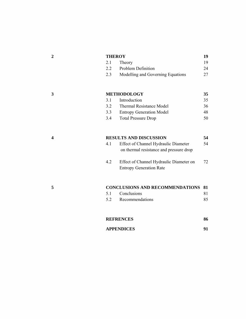
2 THEROY 19 2.1 Theory 19 2.2 Problem Definition 24 2.3 Modelling and Governing Equations 27
3 METHODOLOGY 35 3.1 Introduction 35 3.2 Thermal Resistance Model 36 3.3 Entropy Generation Model 48 3.4 Total Pressure Drop 50
4 RESULTS AND DISCUSSION 54 4.1 Effect of Channel Hydraulic Diameter 54
on thermal resistance and pressure drop
4.2 Effect of Channel Hydraulic Diameter on 72 Entropy Generation Rate
5 CONCLUSIONS AND RECOMMENDATIONS 81 5.1 Conclusions 81 5.2 Recommendations 85
REFRENCES 86
APPENDICES 91
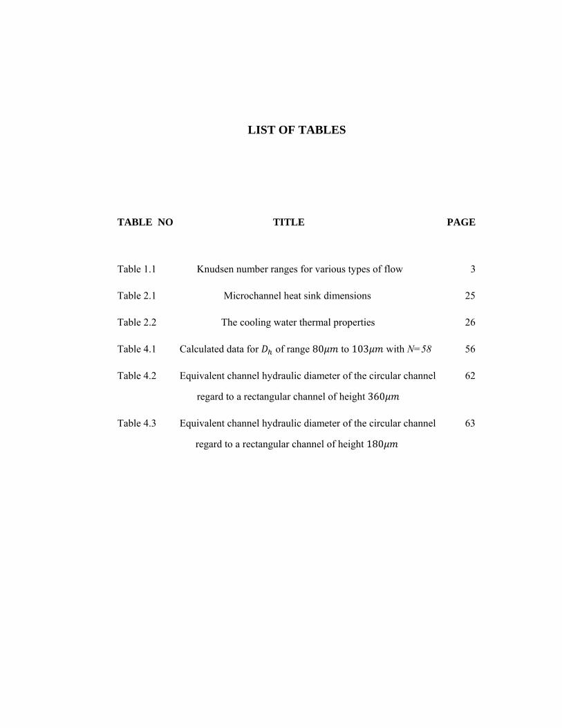
LIST OF TABLES
TABLE NO TITLE PAGE
Table 1.1 Knudsen number ranges for various types of flow 3
Table 2.1 Microchannel heat sink dimensions 25
Table 2.2 The cooling water thermal properties 26
Table 4.1 Calculated data for of range 80 to 103 with N=58 56
Table 4.2 Equivalent channel hydraulic diameter of the circular channel 62
regard to a rectangular channel of height 360
Table 4.3 Equivalent channel hydraulic diameter of the circular channel 63
regard to a rectangular channel of height 180

LIST OF FIGURES
FIGURE NO TITLE PAGE
Figure 1.1 The interdisciplinary field covered by the 4
method of thermodynamic optimization, or
entropy generation minimization.
Figure 1.2 A sketch of a nanochannel filled with a 7
simple fluid. The filled circles denote the
channel wall atoms, and the open circles
denote the fluid atoms. The fluid atoms
interact with each other by a Lennard–Jones
potential VLJ,1, and the fluid atoms interact
with the wall atoms by a Lennard–Jones
potential VLJ,2.
Figure 1.3 Sketch of a typical radial distribution 8
function (RDF) g(r). RDF measures
the probability density of finding a particle
at a distance r from a given particle.

FIGURE NO TITLE PAGE
Figure 2.1 Circular microchannel heat sink and cross-section 22
of its unit cell.
Figure 2.2 Structure of a circular microchannel heat sink 24
and the unit cell
Figure 2.3 Entrance length of the microchannel for channel 27
hydraulic diameter of range 80 to 103
with 58
Figure 2.4 entropy change of a control mass during an 32
irreversible process
Figure 3.1 A circular microchannel control volume 37
Figure 3.2 A curved fin with adiabatic tip 39
Figure 3.3 circular channel and the simplified fin model 42
Figure 3.4 A model of microchannel convective heat transfer. 48
Figure 4.1 Effect of channel hydraulic diameter of range 55
80 to 103 with 58 on
Figure 4.2 Effect of channel hydraulic diameter of range 56
80 to 103 with 58 on total pressure drop
Figure 4.3 Effect of heat flux with channel diameter of range 58
80 to 103 and 58 on thermal resistance

FIGURE NO TITLE PAGE
Figure 4.4a Effect of pumping power with channel diameter 59
of range 80 to 103 and 58 on
Reynolds Number
Figure 4.5 Effect of pumping power with channel diameter 61
of range 80 to 103 and 58 on
thermal resistance
Figure 4.6a Effect of the equivalent channel hydraulic diameter 64
of the circular channel regard to a rectangular channel
of height 360 on thermal resistance
Figure 4.7 Effect of the equivalent channel hydraulic diameter 65
of the circular channel regard to a rectangular channel
of height 180 on thermal resistance
Figure 4.8a Effect of the equivalent channel hydraulic diameter 66
of the circular channel regard to a rectangular channel
of height 360 with N=40 on fin efficiency
Figure 4.9 Effect of the equivalent channel hydraulic diameter 67
of the circular channel regard to a rectangular channel
of height 360 on pressure drop
Figure 4.10 Effect of the equivalent channel hydraulic diameter 68
of the circular channel regard to a rectangular channel
of height 180 on pressure drop

FIGURE NO TITLE PAGE
Figure 4.11 Effect of N on thermal resistance under channel 69
hydraulic diameter constraint of range 40 to 80
Figure 4.12 Effect of N on pressure drop under channel hydraulic 70
diameter constraint of range 40 to 80
Figure 4.13 Effect of N on fin efficiency under channel hydraulic 71
diameter constraint 40
Figure 4.14a Effect of channel hydraulic diameter of range 73
80 to 103 with 58 on entropy generation,
Figure 4.15 Effect of heat flux with channel diameter of range 74
80 to 103 and 58 on entropy generation,
Figure 4.16 Effect of pumping power with channel diameter of 75
range 80 to 103 and 58 on
entropy generation,
Figure 4.17a Effect of the equivalent channel hydraulic diameter of 77
the circular channel regard to a rectangular channel of
height 360 on entropy generation,
Figure 4.18a Effect of the equivalent channel hydraulic diameter of 78
the circular channel regard to a rectangular channel of
height 180 on entropy generation,
Figure 4.19 Effect of N on entropy generation under channel 79
hydraulic diameter constraint of range 40 to 80

LIST OF SYMBOLS
a - fin height [m]
b - fin bottom width [m]
- cross-section area of a circular channel [ ]
- total effective heat transfer area [ ]
- cross-section area of a curved fin [ ]
- specific heat of fluid [J/kg.K]
- hydraulic diameter [m]
- energy [J]
- energy rate [J/s]
∆ - energy change [J]
f - friction factor
h - specific enthalpy of the fluid [J/kg]
- average heat transfer coefficient [W/ . C]
- thermal conductivity of solid [W/m. C]
- ratio of thermal conductivity of fluid to solid /
- thermal conductivity of fluid [W/m. C]
- Knudsen number
- entrance length [m]
- total length of microchannel heat sink [m]

- total height of microchannel heat sink [m]
- total width of microchannel heat sink [m]
- fin parameter [ ]
- mass flow rate [kg/s]
N - total number of microchannels
- Nusselt number based on hydraulic diameter
- pressure [Pa]
- fin perimeter [m]
- pumping power [W]
∆ - total pressure drop [Pa]
- Peclet number based on hydraulic diameter
Pr - Prandtl number
‐ wall heat flux [W/m ]
‐ uniform wall heat flux [W/m ]
Q - heat transfer [J]
- rate of heat transfer [W]
- heat transfer rate from the base [W]
- heat transfer rate from the fin [W]
- radial coordinate [m]
- internal radius of microchannel [m]
- gas constant [J/ . C]
- thermal resistance [W/ C]
- Reynolds number based on hydraulic diameter
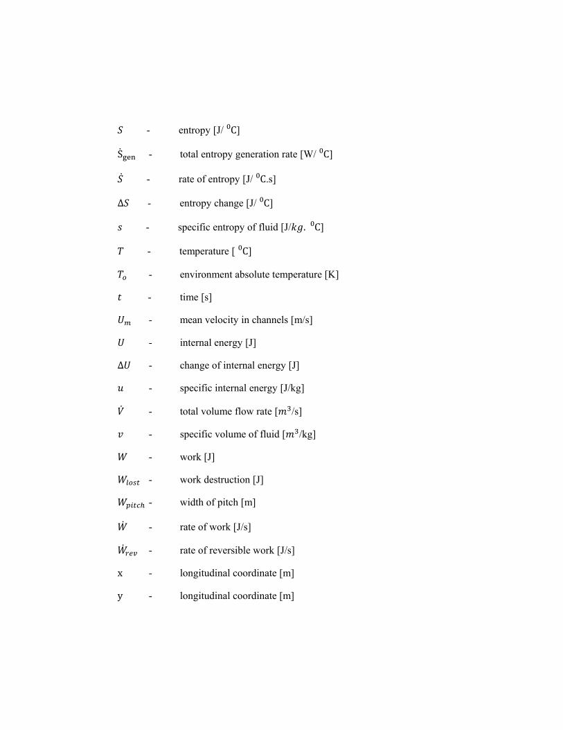
- entropy [J/ C]
S - total entropy generation rate [W/ C]
- rate of entropy [J/ C.s]
∆ - entropy change [J/ C]
- specific entropy of fluid [J/ . C]
- temperature [ C]
- environment absolute temperature [K]
- time [s]
- mean velocity in channels [m/s]
- internal energy [J]
∆ - change of internal energy [J]
- specific internal energy [J/kg]
- total volume flow rate [ /s]
- specific volume of fluid [ /kg]
- work [J]
- work destruction [J]
- width of pitch [m]
- rate of work [J/s]
- rate of reversible work [J/s]
x - longitudinal coordinate [m]
y - longitudinal coordinate [m]

Greek Symbols
∆ - pressure drop across microchannel
α - thermal diffusivity [ / ]
α - channel diameter to microchannel heat sink width ratio
α - heat sink aspect ratio
β ‐ channel diameter to channel pitch ratio
γ - ratio of specific heat /
µ - absolute viscosity of fluid [kg/m.s]
ηf - fin efficiency
- temperature difference, [ ]
- base stream temperature, [ ]
υ - kinematic viscosity of fluid [m /s]
ρ - fluid density [kg/m ]
λ - mean free path of the gas
subscripts
a - ambient
av - average
b - base
conv - convective
CV - control volume
eq - equivalent

f - fluid
fin - single fin
gen - generation
hs - heat sink
i - inner
in - entrance
int rev - internally reversible
lost - destruction
m - mean value
out - exit
rev - reversible
w - wall
1 - initial
2 - final

LIST OF APPENDICES
APPENDIX TITLE PAGE
Appendix A-1 Measured Nusselt number from experimental 91
results (Yang and Lin, 2007).
Appendix A-2 Friction factor from experimental results 92
(Yang and Lin, 2007).
Appendix A-3 measured friction factor from experimental 93
results for (a) fused silica tubes, and (b) stainless
steel tubes (Li et al, 2007).
Appendix A-4 Local distribution of the Nusselt number 94
of tube No.4 at different Reynolds (Li et al, 2007).
Appendix A-5 Local distribution of the Nusselt number 95
of tube No.5 at different Reynolds (Li et al, 2007).
Appendix A-6 Local distribution of the Nusselt number 96
of tube No.6 at different Reynolds (Li et al, 2007).
Appendix B-1 MATLAB R2008a Code 97
Appendix C-1 Effect of α with β=0.6 and N=100 (W =100 μm) 100
on (a) thermal resistance, and (b) total pressure
drop (Abidin, 2006).

APPENDIX TITLE PAGE
Appendix C-2 Effect of (a) heat flux, and (b) pumping power at α of 101
range 2 to 6 with β=0.6 and N=100 (W =100 μm)
on thermal resistance (Abidin, 2006).
Appendix C-3 Effect of β on thermal resistance under channel height 102
constraint,(a) H =360µm, and (b) H =180µm
(Abidin, 2006).
Appendix C-4 Effect of β on total pressure drop under channel height 103
constraint,(a) H =360µm, and (b) H =180µm
(Abidin, 2006).
Appendix C-5 Effect of N on (a) thermal resistance, and (b) total 104
pressure drop under channel height constraint,
H =360µm (Abidin, 2006).
Appendix C-6 Effect of α of range 2 to 6 with β=0.6 and N=100 105
(W =100 μm) on entropy generation, S
(Abidin, 2006).
Appendix C-7 Effect of (a) heat flux, and (b) pumping power for 106
α of range 2 to 6 with β=0.6 and N=100
(W =100 μm) on entropy generation, S (Abidin, 2006).
Appendix C-8 Effect of β on entropy generation under channel 107
height constraint, (a) H =360µm, and (b) H =180µm
(Abidin, 2006).

APPENDIX TITLE PAGE
Appendix C-9 Effect of N on entropy generation under channel 108
height constraint, (a) H =360µm, and (b) H =180µm
(Abidin, 2006).

1
CHAPTER 1
INTRODUCTION
1.1 Background
Micron- and submicron-size mechanical and biochemical devices are
becoming more prevalent both in commercial applications and in scientific inquiry.
Small accelerometers with dimensions measured in microns are being used to deploy
air bag systems in automobiles. Tiny pressure sensors for the tip of a catheter are
smaller than the head of a pin. Microactuators are moving scanning electron
microscope tips to image single atoms. Novel bioassays consisting of microfluidic
networks are designed for patterned drug delivery. New fabrication techniques, such
as surface silicon micromachining, bulk silicon micromachining, Lithographie
Galvanoformung Abformung (LIGA), and Electro Discharge Machining (EDM) have
been successfully applied to micro fabrication in recent years, making these
microdevices possible. The capability to batch fabricates and automate these
fabrication technologies makes such microdevices inexpensive. New nanofabrication
techniques have emerged exploiting the concept of self-assembly for submicron-size
objects.
The operation of most of the electronic devices is strongly influenced by their
temperature and the thermal environment near them. As an example, the present
computer technology owes much of its progress to the miniaturization of circuits of
2
silicon chip. The demand for faster circuits and increased capacity, has led to an
increase in power densities and a need for continuous improvement in the methods of
heat removal.
Microchannel heat sink is known for its excellent cooling capacity due to the
high surface to volume ratio that enhances heat removal. Tuckerman and Pease first
realized the potential of this technology and initialled the foundation for silicon based
micro-channel heat sink experimentation (Tuckerman, D.B., and Pease, R.F.W.,
1981). Later on Samalam reported correlations for thermal resistance (Samalam, V.K.
1989) based on the theoretical study of the experiments by Tuckerman. Fedorov and
Viskanta carried out numerical simulation (Federov, A.G., Viskanta, R., 1999) based
on the experimental data. Qu and Mudawar computed a 3-D fluid flow and heat
transfer study on micro-channel with rectangular cross-section (Mudawar, I., and Qu,
W., 2002). Li et al. numerically investigated 3-D conjugate heat transfer in a silicon
based micro-heat sink [2-D fluid flow and 3-D heat transfer] (Li et al, 2004). Toh et
al. (Toh et al., 2002) carried out the detailed numerical study of variation of local
thermal resistance and friction factor along the flow direction in micro-channels of
different cross-section (Toh et al., 2002). Li and Peterson parametrically optimized
the micro-channel geometry for various numbers of channels and cross-sections of
micro channel (Li and Peterson, 2006). The major part of works was to investigate the
microchannels design parameters. Micro channels are normally known for their low
Reynolds numbers, high pressure drop and heat transfer coefficient. Kandlikar S.G.
(Kandlikar S.G., 2003) in their paper discussed the importance of rarefaction effects
in gas flow, electric double layer, entrance region, developing flows and experimental
errors in microchannels study. One of the important parameters in microchannel study
is the Knudsen number (Kn) which is a measure of the departure from the continuum.
Knudsen number is defined as the ratio of the mean free path of the gas to the
hydraulic diameter of the flow channel
( (1.1)
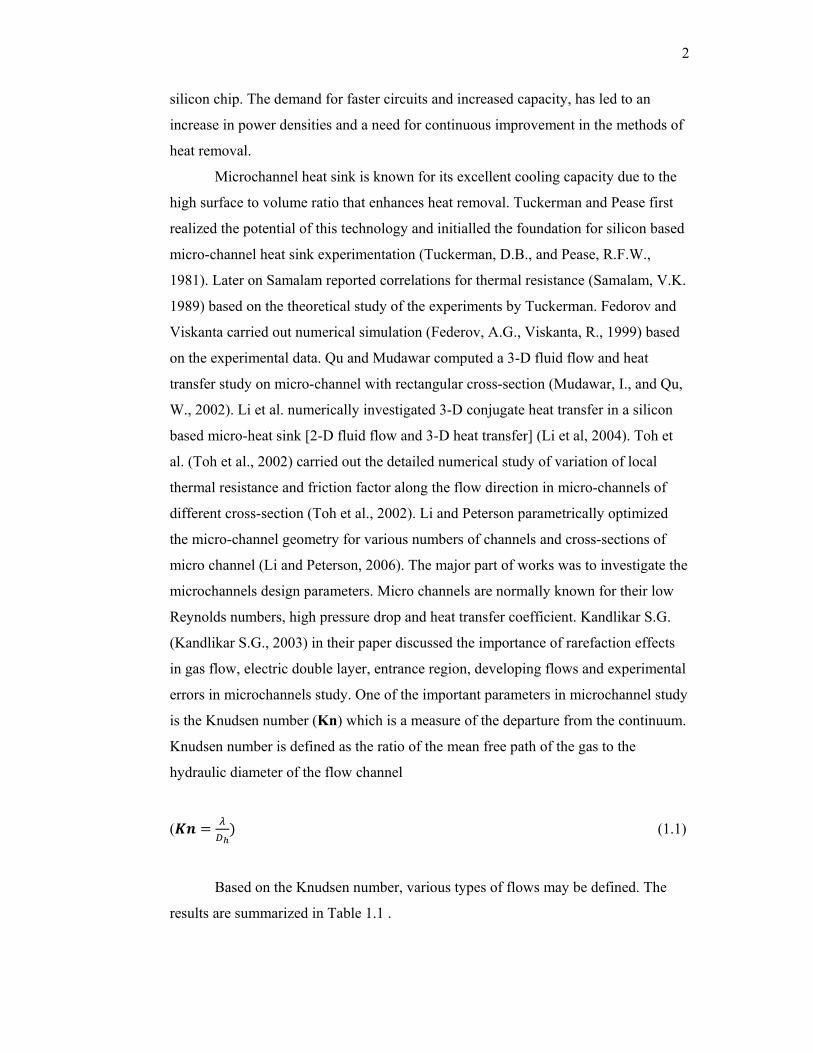
Based on the Knudsen number, various types of flows may be defined. The
results are summarized in Table 1.1 .

3
Table 1.1 Knudsen number ranges for various types of flow (Kandlikar S.G., 2003)
Rang of Knudsen Numbers Type of Flow
0.001>Kn Continuum Flow: no rarefaction effects
0.1>Kn>0.001 Slip Flow: rarefaction effects that can be
modelled with a modified continuum theory
accounting for wall slip
10>Kn>0.1
Transition Flow: a type of flow between slip
flow and free molecular flow that is analyzed
statistically; i.e. with Boltzman equation
Kn>10 Free Molecular Flow: motion of individual
molecules must be modelled and then treated
statistically
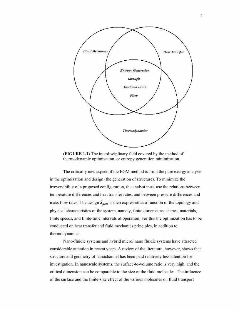
Thermodynamic optimization or entropy generation minimization (EGM) of
systems involves analysis of multidisciplinary areas of heat transfer, engineering
thermodynamics, and fluid mechanics. The position of the field may be described by
Figure 1.1. Principles of heat and mass transfer, fluid mechanics, and engineering
thermodynamics are simultaneously applied to model processes, devices, and
installations which account for the inherent irreversibility of engineering systems and
processes. Entropy generation is similar to exergy destruction; but with difference of
relying on heat transfer and fluid mechanics, as well as thermodynamics.
For a general system-environment configuration based on Gouy-Stodola
theorem (Bejan A., 1996a),
W W T S (1.2)
The lost power W W is always positive, regardless of whether the
system is a power producer (e.g. power plant) or a power user (e.g. refrigeration
plant). Minimizing the lost power is the same as maximizing the power output in a
power plant, and minimizing the power input in a refrigeration plant. This operation is
also equivalent to minimizing the total rate of entropy generation.
4
(FIGURE 1.1) The interdisciplinary field covered by the method of thermodynamic optimization, or entropy generation minimization.
The critically new aspect of the EGM method is from the pure exergy analysis
in the optimization and design (the generation of structure). To minimize the
irreversibility of a proposed configuration, the analyst must use the relations between
temperature differences and heat transfer rates, and between pressure differences and
mass flow rates. The design is then expressed as a function of the topology and
physical characteristics of the system, namely, finite dimensions, shapes, materials,
finite speeds, and finite-time intervals of operation. For this the optimization has to be
conducted on heat transfer and fluid mechanics principles, in addition to
thermodynamics.
Nano-fluidic systems and hybrid micro/ nano fluidic systems have attracted
considerable attention in recent years. A review of the literature, however, shows that
structure and geometry of nanochannel has been paid relatively less attention for
investigation. In nanoscale systems, the surface-to-volume ratio is very high, and the
critical dimension can be comparable to the size of the fluid molecules. The influence
of the surface and the finite-size effect of the various molecules on fluid transport

5
needs to be understood in detail, while such effects may be largely neglected for
liquid flows in macroscopic channels.
6
1.2 Nanochannel
With the growing interest in the development of faster, smaller and more
efficient biochemical analysis devices, nanofluidics systems and hybrid micro/nano
fluidics systems have attracted considerable attention in recent years. A key difference
between the simulation of the fluidics transport in confined nanochannels, where the
critical channel dimension can be a few molecular diameters, and at macroscopic
scales is that the well-established continuum theories (Navier-Stokes equations) may
not be valid in confined nanochannels. Therefore, atomistic scale simulations, in
which the fluid atoms are modelled explicitly, and the motion of the fluid atoms is
calculated directly, give fundamental insights on fluid transport. The most popular
technique for atomistic simulation of liquid transport is molecular dynamics (MD).
Two major kinds of flow in nanochannels are “simple fluid flow and water
flow” which are of high importance in nanochannel study. Simple fluid is a collection
of molecules that interact via the Leonard-Jones potential which will be defined later.
The dynamics follow the classical mechanics (Newton’s second law). In practice
some noble gases (e.g., argon) can be modelled fairly accurately as a simple fluid.
Main advantages of the study of simple fluids are:
1. Much lower computational cost is required compared to complex fluids.
2. Despite its simplicity, it has a deeper insight into physics of fluid transport in
nanochannels.
3. Generates data for validation of theories describing fluid transport in nanochannels
Simple fluids can be described by the Lennard-Jones (LJ) potential:
4 (1.3)
Where ε is related to the interaction strength, σ is the interaction length scale
and r is the distance. Since forces due to LJ potential can be evaluated numerically
and describes the interaction between nonpolar molecules quite well, LJ is the most
popular interaction potential used in MD simulations. In the MD simulation of LJ
fluids, the physical quantities are computed using reduced units.

7
Depending on the critical length scale of the channel, the fluidic transport
behaviour can either deviate significantly from the classical continuum theory
prediction or be very similar to the transport of a bulk fluid described by the classical
theory. These observations follow from the fact that when the fluid atoms are
confined to molecular channels, the fluid can no longer be taken to be homogeneous,
and strong oscillations in fluid density occur near the fluid-solid interface. Therefore,
the dynamic behaviour of the fluid significantly differs from that of the bulk.
(FIGURE 1.2) A sketch of a nanochannel filled with a simple fluid. The filled circles denote the channel wall atoms, and the open circles denote the fluid atoms. The fluid atoms interact with each other by a Lennard–Jones potential VLJ,1, and the fluid atoms interact with the wall atoms by a Lennard–Jones potential VLJ,2. Karniadakis (Karniadakis et al., 2005)
Some features which must be considered for a simple fluid MD simulation;
Density Distribution- The strong density oscillation of fluid atoms near the
fluid/solid interface are a universal phenomenon which has been observed in almost
all MD simulations of nanofluidic flows and has been verified experimentally
Radial Distribution Function- Density fluctuation near a channel wall can be
expressed using the concept of a radial distribution function (RDF). RDF (g(r))
measures the probability density of finding a particle at a distance of r. The fluid
laying near the channel wall is mainly induced by the structure of fluid RDF and the
structure of the solid wall.
Simple fluids in nanochannels are inhomogeneous because of the strong
layering of fluid atoms near the channel wall. Classical fluid transport theories do not
account for the inhomogeneity of the fluid, and transport parameters such as

8
diffusivity and viscosity are strongly influenced by the fluid layering in nanochannels.
Fluid layering can be influenced by various parameters such as the wall structure,
fluid-wall interactions, and channel width.
(FIGURE 1.3) Sketch of a typical radial distribution function (RDF) g(r). RDF measures the probability density of finding a particle at a distance r from a given particle (r = 0 corresponds to the position of the given particle). Karniadakis (Karniadakis et al., 2005)
Fluid-Wall Interactions- The interaction between a fluid atom and a wall atom is
usually modelled by LJ potential. The LJ parameters for fluid-fluid and fluid-wall
interactions are denoted by (ε, σ) and ( , ) respectively. A higher
corresponds to stronger interaction between the fluid and wall atoms.
Effects of Nanochannel width- it is found that for channels wider than 10σ, the fluid
layers near the wall are independent of channel width and the central fluid behaves
more like bulk fluid.
Structure of the Wall Atoms- Smooth walls as well as walls with atomistic structure
have been widely used in the MD simulation of nanofluid confined in nanoscale
channels. It has been realized that for smooth wall, the wall-fluid potential depends on
the normal distance between the fluid atom and the channel wall, whilst for a wall
with atomistic structure, the wall-fluid potential depends on the relative distance
between the fluid atom and each atom wall.
Diffusion Transport- Diffusion transport is typically important in most nanofluidic
systems. This can be understood by Peclet number, indicating that diffusion can either
dominates the transport or is as important as the bulk transport.

9
Validity of the Navier-Stokes Equations- During the last several years, researchers
have used MD simulations to test the accuracy of the Navier-Stokes equations in
nanochannels (Koplik et al., 1987, Travis and Gubbins, 2000). In the continuum fluid
transport theory governed by Navier-Stokes equations, it is assumed that the state
variables (density, temperature) do not vary appreciably over length and timescale
comparable to the molecular free path and molecular relaxation time. It was shown
that the fluid density near the solid-liquid interface can vary significantly over
intermolecular distances. While these local density oscillations may not necessarily
mean the breakdown of the continuum theory, it is important to understand how the
continuum theory works for liquids in confined channels.
Boundary Conditions at Solid-Liquid Interfaces- It is shown that the MD
simulations systemically underpredict the slip length deduced from various
experiments, specifically, predict a slip length roughly ten times smaller than in the
experiments. Such a large discrepancy implies that there are some other physical
phenomenons not included in the simulation. Molecular slippage, gaseous film, no-
shear/no-slip patterning and viscosity model are other conceptual models of slip.
Molecular Dynamics (MD) Method- This is suitable for simulating very
small volumes of liquid flows, with linear dimensions on the order of 100nm or less
and for time intervals of several tenths of nanoseconds. It can deal effectively with
nanodomains and it is perhaps the only accurate approach in simulating flows
involving very high shear where the continuum may not be valid. For dimensions less
than approximately ten molecules, the continuum hypothesis breaks down even for
liquids and MD should be employed to simulate the atomistic behaviour of such a
system. MD is, however, inefficient for simulating microflows due to the large
intermolecular distances that require relatively large distances. Gas microflows are
simulated more efficiently using direct simulation Monte Carlo (DSMC) method. Another emerging application of MD simulation is investigation of the fluid thermal
behaviour of nanotubes.
Molecular dynamics (MD) computes the trajectories of particles that model
the atoms of the system, since they result from relatively simple force fields. The MD
simulations generate a sequence of points in phase space as a function of time, these
points belong to the same ensemble, and they correspond to the different
conformations of the system and their respective momenta. An ensemble is a

10
collection of points in phase space satisfying the conditions of particular
thermodynamics state. Several ensembles, with different constraints on the
thermodynamic state of the system are commonly used in MD.
The motion of an ensemble of atoms in MD simulations is governed by
interatomic forces arising from interaction of electrons and nuclei. Thus, the results
obtained from MD simulations are linked with ability of the potential energy function
to represent the underlying system. In classical MD simulation, first, a model system
consisting of N particles is selected and Newton’s equations of motion are solved
until the properties of the system no longer change with time. Once a steady state is
reached, the required measurements are performed.
The key steps in MD simulation are:
1. Initialization: Initial positions and velocities must be assigned to N particles.
2. Force calculation: Forces due to the interactions are computed.
3. Integration of the equations of motion: Verlet integration rule
4. Data storage and analysis: After the equations of motion are integrated, the
relevant properties of the system (temp., press...) are calculated and then stored.
The definition of accurate intermolecular potentials is the key to any atomistic
simulation, and therefore, for MD simulation. Consequently, calculation of the
potential function and the associated force accounts for most of the computational
cost in an atomistic simulation. As a result, it is considered as one of the major
components during the nano investigations.
Published studies currently available show that nanoscale devices and
nanochannels design technology is in the earliest stages. Governing theories have not
been really established and for some, microscale and nanoscale systems considered as
one and the same. Thus this study will look into the entropy minimization of a
microchannel system, specifically the circular geometry design. Since the fluidic
transport behaviour involve similar characteristics, the results obtained may be
conservatively used in the nanochannel study.

11
1.3 Microchannel Heat Sink
The problem of achieving compact, high-performance forced liquid cooling of
integrated circuits first was investigated by Tuckerman and Pease (Tuckerman and
pease, 1981). They found that for laminar flow in confined channels, the use of high-
aspect ratio channels for increased surface area will, to an extent, further reduce
thermal resistance. Based on this consideration, a compact, water-cooled integral heat
sink for silicon integrated circuits was designed and tested. The experimental work
revealed the capability of heat dissipation up to a maximum power of 790 / of
the compact water-cooled heat sink. Since that experiment, there have been many
experimental and analytical investigations on microchannel heat sinks and their
thermal and fluidic performances.
Later on Knight (Knight et al, 1991) showed that for a fully developed flow in
closed finned channels, there was an optimal geometrical design of the size and
number of cooling channels to increase the heat transfer. Using maximum allowable
pressure drop through the cooling channels, an optimization scheme was described
and was compared with previously published case by Tuckerman and Pease (1981) for
water-cooled Silicon wafers. Results showed that a significant reduction of thermal
resistance was obtained by using fin/channel dimensions. Beside that work, Knight
(Knight et al, 1992) tried to develop theoretical optimization procedures to minimize
the overall thermal resistance of microchannel heat sinks for a given pressure drop.
He presented the governing equations for fluid dynamics and heat transfer in the heat
sink in a dimensionless form and then presented a scheme for solving these equations.
Solution procedure for both laminar flow and turbulent flow through the channels was
presented.
A high performance forced air cooling scheme was investigated theoretically
and experimentally by Kleiner (Kleiner et al, 1995) which was employing
microchannel parallel plate-fin heat sinks using air. During the work sample heat
sinks with lateral dimensions of 5×5 cm2 and fin lengths of 1.5 and 2.5 cm were
fabricated from copper and aluminium foils and cooling system performance was
modelled in terms of thermal resistance, pressure drop, and pumping power. A fin
thicknesses and channel widths on the order of 200 and 500 μm, respectively was
used and Thermal resistances at the rate of 0.2 R/W was measured. In comparison
12
with the prior works dealing with direct air cooling, it was concluded that the
investigated cooling approach possessed an acceptable performance.
Some three-dimensional models have also been developed. Continuum model
derived from Navier-Stokes equation has been applied numerically to illustrate the
transport mechanism of micro channel heat sinks. The work done by Federov and
Viskanta (Federov and Viskanta, 1999) was to investigate flow and conjugate heat
transfer in the microchannel-based heat sink for electronic packaging applications.
The incompressible laminar Navier–Stokes equations of motion were employed as the
governing conservation equations which were solved numerically using finite-volume
method. The validation of the theoretical model developed was done by comparing
thermal resistance and the friction coefficient with available experimental data for a
wide range of Reynolds numbers. The analysis shed a unique fundamental insight into
the complex heat flow pattern established in the channel due to combined convection–
conduction effects in the three-dimensional setting.
The other investigation on three-dimensional numerical analysis was carried
out to analyse fluid flow and heat transfer in a rectangular micro-channel heat sink
numerically using water as the cooling fluid. Qu and Mudawar (Qu and Mudawar,
2002) simulated a heat sink which consist of a 1-cm2 silicon wafer with micro-
channels width of 57 μm and depth of 180 μm. They also developed a numerical code
based on the finite difference method and the SIMPLE algorithm to solve the
governing equations and validated by comparing the predictions with analytical
solutions and available experimental data. It was found that the temperature rise along
the flow direction in the solid and fluid regions can be approximated as linear. Flow
Reynolds number affects the length of the flow developing region .It was concluded
that for a relatively high Reynolds number of 1400, fully developed flow may not be
achieved inside the heat sink. Although the classical fin analysis method is a
simplified means to modelling heat transfer in micro-channel heat sinks, some key
assumptions introduced in the fin method deviated significantly from the real
situation, which could compromise the accuracy of the method. It was also understood
that increasing the thermal conductivity of the solid substrate reduces the temperature
at the heated base surface of the heat sink, especially near the channel outlet.
13
In another study, Qu and Mudawar (Qu and Mudawar, 2002) tested a
microchannel heat sink 1cm wide and 4.8cm long. The microchannels machined in
the heat sink were 231µm wide and 712µm deep. Apart from this they also presented
numerical analysis for a unit cell containing a single microchannel and surrounding
solid. The measured pressure drop across the channels and temperature distribution
showed good agreement with the numerical results. They concluded that the
conventional Navier-Stokes and energy equations remain valid for predicting fluid
flow and heat transfer characteristics in microchannels.
Ryu (Ryu et al, 2002) performed numerical optimization of thermal
performance of microchannel heat sinks. The objective of the optimization was to
minimize thermal resistance. They varied the channel width, channel depth and the
fin thickness to come up with an optimized solution. Their observation was that the
channel width is the most important parameter dictating the performance of a
microchannel heat sink.
Different works have been conducted to investigate the effect of micro
channel heat sink geometry on its performance. Upadhye and Kandlikar (Upadhye
and Kandlikar, 2004) analyzed direct cooling of an electronic chip of a function of
channel geometry for single-phase flow of water. With fully developed laminar flow
consideration and constant wall temperature and constant channel wall heat flux
boundary conditions, the effect of channel dimensions on the pressure drop, the outlet
temperature of the cooling fluid and the heat transfer rate was presented. A few
conclusions were made. The results indicated that a narrow and deep channel results
in improved heat transfer performance for a given pressure drop constraint.
One of the most comprehensive three dimensional model was developed by
Li et al. (Li et al, 2004) A detailed numerical simulation of forced convection heat
transfer occurring in silicon-based microchannel heat sinks was conducted using a
simplified three-dimensional conjugate heat transfer model with a 2D fluid flow and
3D heat transfer. This model was developed using a finite difference numerical code
with a Tri-Diagonal Matrix Algorithm (TDMA) to solve the governing equations and
provided detailed temperature and heat flux distributions in the microchannel heat
sink. The investigation was done to understand the influence of the geometric
parameters of the channel and the thermo physical properties of the fluid on the flow

14
and heat transfer. The results were presented and it was found that thermo physical
properties of the liquid can significantly influence both the flow and heat transfer in
the microchannel heat sink. Apart from that work, Li and Peterson (Li and Peterson,
2006) investigated the most optimized geometry of a microchannel with liquid flow
for the same numerical model as Li et al. (Li et al, 2004). It was concluded that the
optimal number of channels was 120 per cm with the largest possible aspect ratio.
Another investigation on a three dimensional model was conducted by Lee
and Garimella (Lee, P.S, and Garimella, 2006) which was a three-dimensional
numerical simulations for laminar thermally developing flow in microchannels of
different aspect ratios. It was completed under laminar convective heat transfer in the
entrance region of microchannels of rectangular cross-section consideration with
circumferentially uniform wall temperature and axially uniform wall heat flux thermal
boundary conditions. The local and average Nusselt numbers were presented as a
function of the dimensionless axial distance and channel aspect ratio depending on the
temperature and flux distributions obtained. The advantage of the investigation was
that generalized correlations, useful for the design and optimization of microchannel
heat sinks and other microfluidic devices, was proposed for predicting Nusselt
numbers
Beside the various experimental, analytical and numerical works done on the
thermal performance and pressure drops of the microchannel heat sinks, other
experimental, analytical and numerical studies were pioneered to investigate the effect
of microchannel geometry, apart from rectangular cross section, on the microchannel
heat sink. The most popular experiments were those done with trapezoidal cross
section. Qu et al. (Qu et al, 1999) conducted two simultaneous experiments to
investigate flow and heat transfer characteristics of water through trapezoidal silicon
microchannels with a hydraulic diameter ranging from 51 to 169 μm. A numerical
analysis was also carried out by solving a conjugate heat transfer problem involving
simultaneous determination of the temperature field in both the solid and the fluid
regions. The experimental results were compared with the numerical predictions of
heat transfer field and with the predictions from the conventional laminar flow theory.
A significant difference between the experimental data and the theoretical predictions
was found. Experimental results indicated that pressure gradient and flow friction in
15
microchannels are higher than those given by the conventional laminar flow theory
and the experimentally determined Nusselt number is much lower than that given by
the numerical analysis. The measured higher pressure gradient, flow friction and
lower Nusselt numbers are due to the effect of surface roughness of the microchannels
(Qu et al, 1999).
A numerical study devoted to the hydraulic properties of a network of parallel
triangular microchannels was presented by Niklas et al. (Niklas et al, 2005) with
hydraulic diameter of 110 µm. Previous experimental investigations had revealed that
pressure drop through the microchannels system dramatically increases for the
Reynolds number exceeding 10. Numerical simulations were performed by using the
classical system of continuity and Navier-Stokes equations and showed a very good
agreement with the experimental results proving that there is no scale effect for the
microchannels considered. It was also clearly indicated that the excessive pressure
losses in the high Reynolds number range are due to the secondary flows and
separations appearing in several regions of the microchannel system.
A thermal investigation of a polymeric microchannel heat sink was conducted
by Barba et al. (Barba et al, 2005). A geometrical configuration consisting of a
circular microduct with a gas running through it was designed and a three-
dimensional procedure was developed to solve the model. The conjugate heat transfer
problem was solved assuming fully developed laminar flow in forced convection and
considering a gas flow with low Prandtl and Reynolds numbers with a numerical
solution obtained for 2-D coordinates. The theoretical results were compared with
experimental data concerning helium and nitrogen flows in circular microducts and
good agreements were concluded.

16
1.4 EGM Methodology
Bejan first introduced optimization of heat sink using EGM in 1996(Bejan,
1996b). It was found that entropy generation associated thermal resistance and fluid
friction effects, directly evaluate the amount of lost potential for work which in a heat
sink system is equal to the lost ability of system to transfer heat to the surrounding.
He also introduced the fundamentals of the methods of exergy analysis and entropy
generation minimization (Bejan, 2001). The proportionality between exergy
destruction and entropy generation was illustrated by examples of open and closed
systems. Since then there have been some other investigations to utilize EGM
principles to heat sink applications. One of the major works was done by Sahin
(Sahin, 1998) where he applied the method to macro scale ducts with different
geometries considering constant heat flux and laminar flow. It was concluded that if
the frictional contribution of entropy generation become significant, the circular duct
showed the best performance. Ogiso (Ogiso, 2001) presented a method of assessing
the overall cooling performance in the thermal design of electronics. The method was
based on the optimization concept of EGM. In comparison with experimental and
numerical data it was found that the overall cooling performance is increased with
decreasing entropy generation rate.
Culham and Muzychka (Culham and Muzychka, 2001) presented a procedure
that allowed the simultaneous optimization of heat sink design parameters based on
a minimization of the entropy generation associated with heat transfer and
viscous dissipation. All relevant design parameters for plate fin heat sinks,
including geometric parameters, heat dissipation, material properties and flow were
simultaneously optimized to characterize a heat sink that minimizes entropy
generation and in turn results in a minimum operating temperature. For the imposed
problem constraints the model was shown to converge to a unique solution that gave
the optimized design conditions.
Ratts and Raut (Ratts and Raut, 2004) obtained an optimal Reynolds number
for laminar and turbulent flow in tubes considering EGM method to optimize a single-
phase, convective, fully developed flow with uniform and constant heat flux. The

17
study also compared the optimal Reynolds number and minimum entropy generation
for cross sections: square, equilateral triangle, and rectangle with aspect ratios of two
and eight. The authors made a very interesting conclusion that rectangle with aspect
ratio of eight had the smallest optimal Reynolds number, the smallest entropy
generation number, and the smallest flow length. The present study will utilize these
principles to apply the EGM method to different microchannel geometry apart from
rectangle.
A numerical investigation was carried out on the entropy generation due to the
steady laminar forced convection fluid flow through parallel plates microchannel by
Haddad et al.(Haddad et al. 2004) The study was to discuss the effect of Knudsen,
Reynolds, Prandtl, Eckert numbers and the non-dimensional temperature difference
on entropy generation within the microchannel. It was based on the Bejan number. It
was found that the entropy generation within the microchannel decreases as Knudsen
number increases, and increases as Reynolds, Prandtl, Eckert numbers and the non-
dimensional temperature difference increase. They concluded that the contribution of
the viscous dissipation in the total entropy generation increases as Knudsen number
increases over wide ranges of the flow controlling parameters.
Most of optimization objectives of microchannel heat sink were to minimize
thermal resistance for a given pressure drop or to minimize the pump power for a
specified thermal resistance. Khan et al. (Khan et al., 2006) employed the EGM
procedure to optimize the overall performance of microchannel heat sinks which
allowed the combined effects of thermal resistance and pressure drop to be assessed
simultaneously as the heat sink interacts with the surrounding flow field. Air was used
as the cooling fluid in the analysis. The variation of entropy generation rate in the slip
flow region was investigated by altering the aspect ratio, fin spacing ratio, heat sink
material, Knudsen numbers and accommodation coefficients of microchannels. It was
illustrated that volume mass flow rate and channel aspect ratio strongly affected the
entropy generation of three different Knudsen number. Based on new general
expressions developed by Khan et al. (Khan et al, 2006) for the entropy generation
rate, an analytical investigation made use the same principle of minimization of
entropy generation (Abidin U, 2006).

18
1.5 Objective and Scopes
The present study will investigate the application of the entropy generation
minimization method to a circular microchannel heat sink.
The principle of entropy generation relations in circular microchannels will be
inspected. A dimensionless average entropy generation in the circular cross section
will be derived. The ultimate objective is to optimize the circular microchannel heat
sink based on entropy generation minimization. The scopes of this study can be
summarized as
1. To review works on optimization of circular microchannel heat sink.
2. To derive the dimensionless average entropy generation rate in a circular
microchannel.
3. To derive the principle entropy generation minimization correlation for a
circular microchannel heat sink.
4. To compare the derived correlation and obtained results with other
numerical and experimental works.