optimal placement of passive energy dissipation devices...
TRANSCRIPT

Hindawi Publishing CorporationMathematical Problems in EngineeringVolume 2012, Article ID 474282, 21 pagesdoi:10.1155/2012/474282
Research ArticleOptimal Placement of Passive Energy DissipationDevices by Genetic Algorithms
Ji-ting Qu1, 2 and Hong-nan Li3
1 Faculty of Infrastructure Engineering, Dalian University of Technology, Dalian, Liaoning 116024, China2 State Key Laboratory of Structural Analysis for Industrial Equipment, Dalian University of Technology,Dalian, Liaoning 116024, China
3 State Key Laboratory of Costal and Offshore Engineering, Dalian University of Technology, Dalian,Liaoning 116024, China
Correspondence should be addressed to Ji-ting Qu, [email protected]
Received 5 October 2012; Accepted 23 November 2012
Academic Editor: Fei Kang
Copyright q 2012 J.-t. Qu and H.-n. Li. This is an open access article distributed under the CreativeCommons Attribution License, which permits unrestricted use, distribution, and reproduction inany medium, provided the original work is properly cited.
A mathematical model is proposed in this paper for locating optimal positions for passiveenergy dissipative dampers. Three control indices of structural responses with the storey-driftangle, storey displacement, and acceleration are taken in this model. Firstly, six combinationmodes of these indices are presented. On the premise that the number of dampers is fixed, thispaper deals with the optimal placement of two types of passive dampers for several buildingmodels with different number of storeys and seismic ground motions at four types of sitesusing genetic algorithm. Secondly, two estimating indices are presented to assess the reasonablecombination mode of coefficients under different conditions, which can generally express the bestresponse control. Numerical examples are illustrated to verify the effectiveness and feasibilityof the proposed mathematical model. At last, several significant conclusions are given based onnumerical results.
1. Introduction
The technique of energy dissipation belongs to a kind of passive structural control. Thebasic role of passive energy dissipation devices is to absorb or consume a portion of theinput energy from earthquake or wind, reduce the structural response, and protect structuralmembers. These devices are classified as displacement-based and velocity-based dampers inthe China Seismic Code. Among them, metallic yielding damper (MD) and friction damperare the most wildly used displacement-based devices, and their force-deformation responsesonly depend on the relative displacement between each end of device. They could be

2 Mathematical Problems in Engineering
effective on energy dissipation only if slip displacement is reached. Viscoelastic and viscousdampers are the two typically used velocity-based devices. The viscoelastic damper (VED)dissipates vibration energy when viscoelastic material is subjected to shear deformation,thereby reducing the structural response. These devices are applied in seismic control ofbuildings broadly because they rarely need to be repaired after being installed and haveeconomical and simple conformation performance.
It is well known that the installation of dampers will reduce seismic responses ofstructures. To design a structure with energy dissipation devices, the optimal locations ofdevices will have a significant effect on reducing responses and achieving desired designobjectives. Commonly, it may be convenient to distribute the devices to every storey orone storey interval. However, such a placement may be uneconomical and not be the mosteffective means because installation of dampers may increase the stiffness of correspondingstorey and enlarge responses of neighboring stories. Therefore, the research of optimal designcauses designers’ interest.
In the past decades, many researchers have contributed themselves to studies on theoptimal location of dampers in structures. Haftka and Adelman [1] had a study on selectionof actuator locations in large space structures based on worst out in and exhaustive single-point substitution methods. However, this technique leads to a locally optimal solution nearthe starting design guess. Ashour and Hanson [2] suggested placing devices on locationsthat would maximize the damping ratio of the fundamental mode because of its dominancein multistorey buildings’ mode. Zhang and Soong [3] used a simplified sequential searchalgorithm to determine the optimal location of VEDs in an unsymmetrical shear building.Parametric and positioning optimization analyses about VEDs were conducted by Gurgozeand Muller [4] for a linear multi-degree-of-freedom structure. Several other methods wereadopted for location optimization, such as topological approach suggested by Natke andSoong [5], simulated annealing optimization used by Milman and Chu [6], and others byTakewaki [7] and Takewaki et al. [8] made use of a gradient-based method to search foroptimal locations. According to the capability and characteristic of structures with VEDs,Zhou et al. [9] proposed five different optimum design methods for installation of dampersand analyzed an example of a ten-floor reinforced concrete structure. Zhang et al. [10]suggested a convenient and practical methodology about choosing parameters and locationsof VEDs, and effects of controlling of structural vibration for different positions of thesedevices were compared. In practical applications, the location variables are discrete as thenumbers of dampers are fixed. Theoretically, the optimal solution of such a discrete problemcan be obtained by an enumerative search of every possible combination of dampers’position. In fact, the number of feasible locations is too large. Thus, a versatile and flexiblemethod called genetic algorithm was suggested especially for problems whose performanceindex is not a continuous function when the design variable and the variable design spaceare discrete [11–13]. Singh and Moreschi [14] utilized this approach to study the layoutand parametric optimization of viscous and viscoelastic dampers to achieve a desiredperformance. Moreschi and Singh [15] presented a methodology to determine the optimaldesign parameters for the yieldingmetallic and friction devices installed at different locationsin a building for a desired performance objective. An optimal installation method of MRdampers using genetic algorithms was put forward in order to reduce the vibration responseof high-rise building under wind load [16]. Bei and Li [17] gave a new method of improvedgenetic algorithm and quadratic performance index. Five optimal methods were used todetermine the number and location of the magnetorheological dampers in the structure, andseveral principles were pointed out.

Mathematical Problems in Engineering 3
As displacement-based energy dissipative devices present highly nonlinear character-istics, the installation of such dampers in a structure will render it to behave nonlinearly evenif all other structural members are designed to remain linear. Thus, the analysis of structureswith these devices must be done by a step-by-step time history analysis. Investigationson optimal placement of displacement-based dampers are not enough and mainly focuson parametrical optimization. Besides, there are two aspects of shortage [18] needed tobe improved on location optimization of dampers: on one hand, the objective functionssuggested by different scholars are diverse, thus the optimal results are different which canconfuse the designers; on the other hand, the investigations all aim at a given structuresubjected to one earthquake record. Optimal solutions may change for different structuressubjected to various earthquakes. The optimal results derived from one certain earthquakerecord may be unsatisfied for another record.
The main objective of this research is to study the optimal objective functions of twotypes of passive energy dissipation devices with fixed numbers. A new mathematic modelof location optimization will be established, which is suitable for different kinds of passivedampers. Three seismic response performance indices are taken in this model. To achieve theoptimal coefficients of storey-drift angle, acceleration, and storey-displacement indices, thispaper deals with the optimal location of two types of passive dampers for several buildingmodels with different number of storeys and groundmotions at four types of sites. Numericalanalyses are illustrated to verify effective and feasibility of the model for optimal locations ofdampers and structural control, in which a genetic algorithm is used.
2. Analytical Modeling of Passive Energy Dissipation Devices
2.1. Model of Force-Deformation Relation
The displacement-based devices are installed in series with bracings at the interstorey ofstructures. The force-deformation model has often been expressed by the bilinear model.The model of yielding metallic dampers is shown in Figure 1(a), and elastic-perfectly-plasticmodel is used to approximate friction dampers’ model. The combination of a damper andthe bracings is called as the device-brace assembly, and its force is represented as gdb(x). Thestiffness of assembly can be expressed as
kdb0 =kd0kb
kd0 + kb, kdb1 =
kd1kbkd1 + kb
, (2.1)
where kdb0 and kdb1 represent the initialized stiffness and the second stiffness of the assembly;kd0 and kd1 represent the initialized stiffness and the second stiffness of dampers.
The combinational stiffness of assembly for friction dampers can be given by
kdb0 = kb, kdb1 = 0. (2.2)
A number of models of VED with the force-deformation relation have been broughtforward, and they are applicable to different conditions. The equivalent stiffness anddamping model [19] are here adopted for its wide and simple application. The hysteretic

4 Mathematical Problems in Engineering
gd(x1)
gdy
kd0
kd1
xdy x1
+ =
x2
kb
gdb(x)
gdby
xdby x0 00
kbx2
kdb0
kdb1
(a) Yielding device (b) Bracing (c) Yielding element
Figure 1: Force-deformation model of yielding metallic dissipation device.
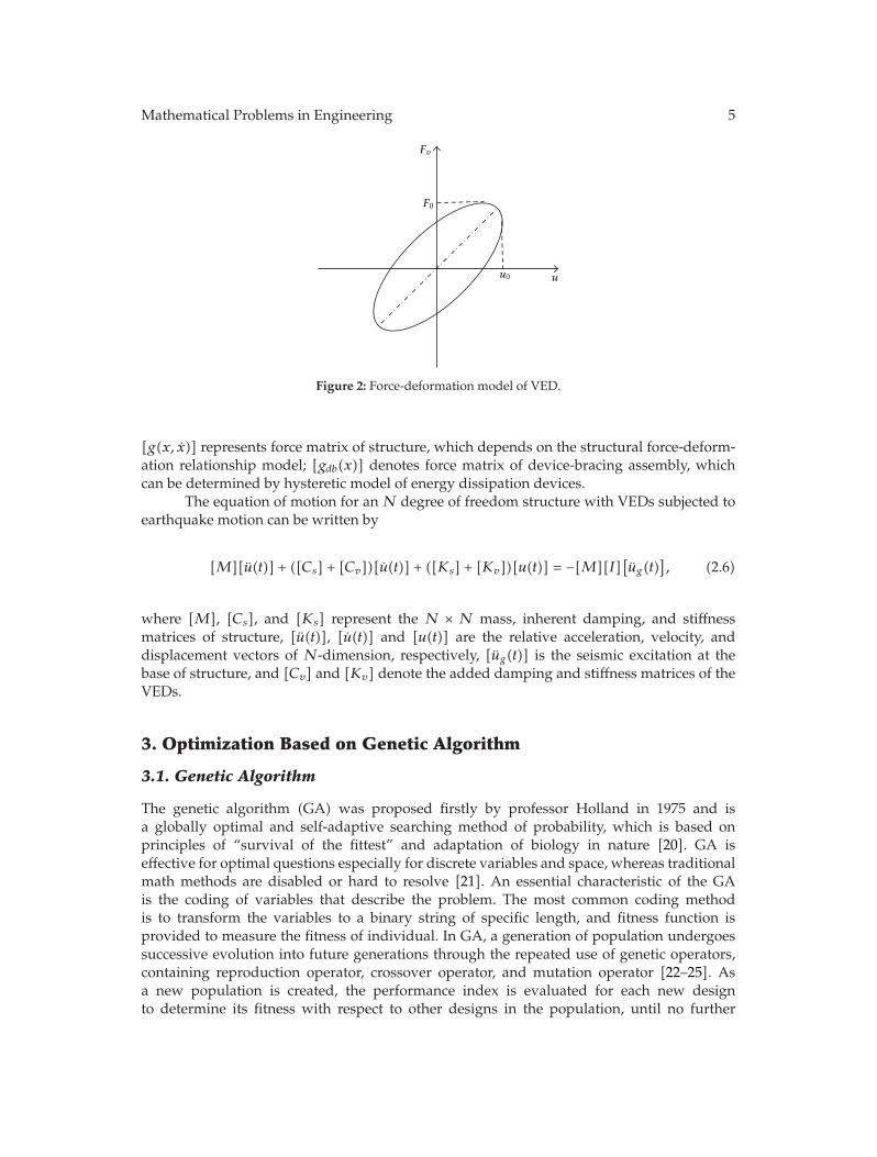
loop of this model is shown in Figure 2. The general formula for the resistance force Fv takesthe following form:
Fv = cv(ω)u + kv(ω)u, (2.3)
where cv(ω) and kv(ω) represent the frequency-dependent damping and stiffness coefficientsfor the dampers, and they can be determined by
cv(ω) =η(ω)G′(ω)A
ωδ, kv(ω) =
G′(ω)Aδ
,
η(ω) =G′′(ω)G′(ω)
,
(2.4)
where G′ and G′′ are defined as the shear storage modulus and the shear loss modulus ofthe VE material, respectively; A represents the area of VE material; δ means the thicknessof the VE material; η(ω) is the loss factor that provides a measure of the energy dissipationcapability of the VE material; ω corresponds to the frequency at which these properties aredetermined.
2.2. System Equations of Controlled Structure
The equation of motion for an N-degree-freedom structure with displacement-based energydissipation devices subjected to earthquake can be written by
[M][X]+ [C]
[X]+[g(x, x)
]+[gdb(x)
]= −[M]
[Xg
], (2.5)
where [M] and [C]mean theN×N mass and inherent dampingmatrices of the structure, [X]is the N-dimensional relative displacement vector with respect to the base, [X] and [X] arerelative velocity and acceleration vector ofN-dimension, [Xg] implies the seismic excitation,
Mathematical Problems in Engineering 5
Fv
F0
u0 u
Figure 2: Force-deformation model of VED.
[g(x, x)] represents force matrix of structure, which depends on the structural force-deform-ation relationship model; [gdb(x)] denotes force matrix of device-bracing assembly, whichcan be determined by hysteretic model of energy dissipation devices.
The equation of motion for an N degree of freedom structure with VEDs subjected toearthquake motion can be written by
[M][u(t)] + ([Cs] + [Cv])[u(t)] + ([Ks] + [Kv])[u(t)] = −[M][I][ug(t)
], (2.6)
where [M], [Cs], and [Ks] represent the N × N mass, inherent damping, and stiffnessmatrices of structure, [u(t)], [u(t)] and [u(t)] are the relative acceleration, velocity, anddisplacement vectors of N-dimension, respectively, [ug(t)] is the seismic excitation at thebase of structure, and [Cv] and [Kv] denote the added damping and stiffness matrices of theVEDs.
3. Optimization Based on Genetic Algorithm
3.1. Genetic Algorithm
The genetic algorithm (GA) was proposed firstly by professor Holland in 1975 and isa globally optimal and self-adaptive searching method of probability, which is based onprinciples of “survival of the fittest” and adaptation of biology in nature [20]. GA iseffective for optimal questions especially for discrete variables and space, whereas traditionalmath methods are disabled or hard to resolve [21]. An essential characteristic of the GAis the coding of variables that describe the problem. The most common coding methodis to transform the variables to a binary string of specific length, and fitness function isprovided to measure the fitness of individual. In GA, a generation of population undergoessuccessive evolution into future generations through the repeated use of genetic operators,containing reproduction operator, crossover operator, and mutation operator [22–25]. Asa new population is created, the performance index is evaluated for each new designto determine its fitness with respect to other designs in the population, until no further

6 Mathematical Problems in Engineering
improvement is observed in the best individual in the subsequent generations, and theoptimal solution is obtained.
3.2. Objective Function
To bring forward an objective function is a core in optimal design. To design a structurewith energy dissipation devices, the optimal location of dampers can make the performanceindices be restricted within desired objectives as the number of dampers is fixed. The optimalsolutions are often diverse when the optimization formulations are different. For example,if the acceleration control is considered as the performance index, the optimal location ofdampers can give a better limit for the acceleration. In the literature, several optimizationformulations were proposed with different indices as follows [10]: (1) the largest relativedisplacement of interstorey; (2) storey-displacement and relative displacement of interstorey;(3) relative displacement of interstorey and the displacement of the peak storey.
These indices all focus on the deformation of structures, which should not be regardedas the only index to be reduced especially for high rise. It is a crucial problem to put forwardan optimization formulation considering different indices of seismic response and confirmthe combination of coefficients for all the indices.
The aim of seismic control of structures is to make structures safe and comfortablein accord with the Codes. Three indices with the storey-drift angle, acceleration, and storeydisplacement can reflect the two aspects of structural performance. Thus, a new objectivefunction of optimal location is presented in this paper, expressed as a linear combination ofthree nondimensional items, considering both security and coziness. In order to avoid theoptimal solution applicable only to the special earthquake excitation, three seismic recordsare used for every kind of site in the step-by-step time history analysis. The optimizationformulation can be written in the following form:
minZ = αθmax
θ0,max+ β
amax
a0,max+ γ
umax
u0,max, (3.1)
where θmax and θ0,max mean the largest storey-drift angles of structure with and withoutadditional energy dissipation devices, umax and u0,max are the largest displacements ofstructure with and without devices, amax and a0,max represent the largest accelerationsof structure with and without devices and, α, β, and γ denote the weight coefficients,respectively, which have different values according to the demand of application inengineering. The combination of the three weight coefficients is given in detail in Section 4.3.
3.3. Optimal Variables
In the context of the problem of optimal location of dampers using GA, optimal variablesneed to be confirmed. They are expressed as a matrix of position P consisting of 0 and 1,which indicates locating a damper if the number is one. Premising a determinate number ofdampers, the optimal variable shows different positions of number 1 and 0. The dimensionof the positional matrix is determined by the storey number of a structure. For example,if dampers are located one at the second, third and forth floor of a 6-storey structure,respectively, the matrix of position can be written as follow: P = [0 1 1 1 0 0].

Mathematical Problems in Engineering 7
3.4. Estimating Indices for Combination Modes of Coefficients
For different form of buildings with different number of storeys and ground motions at fourtypes of sites, the optimal results about six kinds of combination modes of coefficients maybe different. In order to compare these modes with another one to decide which one cangenerate better control of the structures with optimal location of dampers, two estimatingdimensionless indices are proposed, which can be denoted as
J1 =1n
n∑
i=1
(θi,max
θ0, i,max
)2
, J2 =1n
n∑
i=1
(ai,max
a0, i,max
)2
, (3.2)
where θi,max and θ0, i,max imply the mean values of largest storey-drift angle of structureswith and without dampers for the ith floor, ai,max and a0, i,max represent the mean values oflargest accelerations of structures with andwithout the devices, respectively. J1 and J2 all takeresponses of each floor into consideration, which can reflect the response control in general.For six combination modes of coefficients, the two indices should be calculated, respectively,for different buildings with optimal located dampers. The smaller the values of the indicesare, the better the combination mode is.
3.5. Optimal Design Process Based on Genetic Algorithms
(1) Confirm decision-making variables and conditions of restriction, and create astochastic initial population P0.
(2) Optimal formulation is established; namely, confirm the type of objective function(determine the maximum or the minimum value of the objective function).
(3) Design genetic operators, such as select, crossover, and mutation operators.
(4) Make certain related parameters of GA, containing the number of population (M),the terminate generation of genetic operation (T), probability of crossover (pc), andprobability of mutation (pm).
(5) Do step-by-step time history analysis of system by inputting records of earth-quakes, and compute the value of the objective function associated with thesatisfied solution to get the optimal placement of supplemental dampers.
The system analysis and location optimization procedures are programmed by adopt-ing MATLAB programming language. Figure 3 illustrates the optimal design flow chart.
4. Numerical Analyses
In order to realize the optimal locations to diverse structures at different types of sites, threestructures with low, moderate, and high rise height are chosen separately here. The positionaloptimization of displacement-based energy dissipative devices (MD is considered) andvelocity-based devices (VEDs are considered) is processed according to four-site condition.For each type of site, three earthquake records are selected having the close period with thecharacteristic period of corresponding site. The parameters of GA are taken as follows. Theterminate generation of genetic operation is 300. The probabilities of crossover and mutationare 0.8 and 0.2, respectively.

8 Mathematical Problems in Engineering
Randomly generated initial population
Input earthquake records
Step-by-step time history analysis
Evaluate the value
Compute the objective function
Reproduction Crossover Mutation
End
Satisfied
Otherwise
Figure 3: Optimal design flow chart.
4.1. Building Models and Parameters of Dampers
Building 1.
A 5-storey shear building has uniform properties along its height. The mass is 2.0 × 10⁵ kg,the story stiffness is 4.2 × 10⁸ N/m, and the height for each story is 3.3m. The damping ratiois taken as 5%, and the period of structure is obtained with 0.4817 s. 3VEDs or MDs will beinstalled on the structure.
Building 2 (see [9]).
A 10-storey shear building is considered. The mechanical properties of this building aredepicted in Table 1. The damping ratio is 5% and period of structure is 1.4583 s. 6VEDs orMDs are chosen to be placed.
Building 3 (see [26]).
The third structure is a 16-storey shear building. Its mechanical properties are provided inTable 2. The damping ratio is 5%, and period of structure is 2.3848 s. According to the formulaof effective damping ratio attached by energy dissipation in China Seismic Code, seventy-twoVEDs will provide the same effective damping ratio as nine MDs do. So 9MDs or 72VEDsare chosen to be installed.
The typical VED with two viscoelastic layers is designed, where G′ = 1.5 × 10⁷ N/m2,G′′ = 2.01 × 10⁷ N/m2, As = 3 × 10⁻² m2, and δ = 1.3 × 10⁻² m. The working temperature is25◦C. Three initial stiffness of the device-bracing assembly installed on three buildings are

Mathematical Problems in Engineering 9
Table 1:Mechanical properties of 10-storey building.
Floor Mass (kg) Highness (m) Stiffness (N ×m−1)1 1.52 × 10⁶
3.0
2 × 10⁹
2 1.52 × 10⁶ 1 × 10⁹
3 1.349 × 10⁶ 1.43 × 10⁹
4 1.349 × 10⁶ 1.11 × 10⁹
5 1.349 × 10⁶ 1 × 10⁹
6–9 1.349 × 10⁶ 0.769 × 10⁹
10 1.187 × 10⁶ 0.417 × 10⁹
Table 2:Mechanical properties of 16-storey building.
Floor Mass (kg) Highness (m) Stiffness (N ×m−1)1 4.84 × 10⁶ 3.6 5.1 × 10⁹
2 4.67 × 10⁶ 3.0 3.6 × 10⁹
3 4.35 × 10⁶ 3.0 3.8 × 10⁹
4 4.31 × 10⁶ 3.0 3.21 × 10⁹
5–9 4.07 × 10⁶ 3.0 2.54 × 10⁹
10–13 3.81 × 10⁶ 3.0 2.13 × 10⁹
14–16 3.57 × 10⁶ 3.0 1.92 × 10⁹
Table 3: Earthquake records.
Site Group Records Component Interval(s)
Time(s)
Peakvalue
(cm/s2)
IF1F2N1
1985, La Union, Michoacan Mexico1994, Los Angeles Griffith Observation, Northridge
1988, Zhutang, A, Langcang
N00E360S00E
0.010.0050.01
62.7128.7525.32
162.79163.80541.60
IIF3F4N2
1971, Castaic Old bridge Route, San Fernando1979, El Centro, Array no. 10, Imperial valley
1988, Gengma Gengma1
N69WN69WS00E
0.020.010.02
61.8737.0712.36
265.40168.21140.75
IIIF6F7N3
1984, Coyote Lake Dam, Morgan Hill1940, El Centro-Imp Vall Irr Dist, El Centro
1988, Gengma Gengma 2
285270S00E
0.020.020.02
59.9853.4716.56
1137.80210.1090.02
IVF8F9N4
1949, Olympia Hwy Test Lab, Western Washington1981, Westmor and, Westmoreland1976, Tianjin Hospital, Tangshan
35690WE
0.020.020.01
89.1688.4319.19
161.63353.97104.18
2.928×10⁸ N/m, 1.64×10⁸ N/m, and 8×10⁸ N/m. The yield deformation of dampers is takenas 4mm.
4.2. Earthquake Records
Different earthquake records, even though similar intensities, lead to widely varyingresponses, and results based on a single record may not be conclusive. Here, twelveearthquake records are chosen [26] and three for each type of site are shown in Table 3. Thevalues of peak ground accelerations are scaled to 400 gal.

10 Mathematical Problems in Engineering
Table 4: Combination modes of optimal coefficients.
Mode α β γ Objective of optimization
1 1 0 0 Considering storey-drift angle only, namely, security
2 0.7 0.1 0.2 Taking storey-drift angle as the main factor, acceleration, and storeydisplacement as additive factors.
3 0.5 0.3 0.2 Considering the weight of storey-drift angle as half of the importance4 0.1 0.7 0.2 Considering acceleration as the main factor5 0 1 0 Considering acceleration only, namely, amenity6 0.5 0.5 0 Considering only storey drift to reflect deformation of the structure
Table 5: Location optimization of MDs for 5-storey building.
Site Modes 1 and 2 Mode 3 Modes 4 and 5 Mode 6I 1 2 3 1 2 3 1 2 4 1 2 4II 1 2 3 1 2 3 1 2 3 1 2 3III 1 2 3 1 2 3 1 2 5 1 2 5IV 1 2 3 1 2 5 1 2 5/1 3 5 1 2 5Annotation: the numbers in the table represent the floor of optimal location. For example, number 1 and 2mean that dampersare positioned at the first and the second floor of the building.
Table 6: Location optimization of MDs for 10-storey building.
Site Modes 1 and 2 Mode 3 Modes 4 and 5 Mode 6I 2 4 5 6 7 10 2 5 6 7 8 10 2 6 7 8 9 10 1 2 5 6 8 9II 1 2 5 6 7 9 1 2 5 6 7 10 1 2 6 7 8 10 1 2 5 6 7 10III 1 2 3 4 6 7 1 2 5 6 7 10 1 2 6 7 9 10 1 2 3 5 6 7IV 2 3 4 5 6 7 1 2 3 4 5 6 1 2 3 4 5 6 2 5 6 7 8 10
Table 7: Location optimization of VEDs for 10-storey building.
Site Modes 1 and 2 Mode 3 Modes 4 and 5 Mode 6I 2 6 7 8 9 10 2 6 7 8 9 10 5 6 7 8 9 10 2 6 7 8 9 10II 1 2 5 6 7 8 2 5 6 7 8 10 2 6 7 8 9 10 2 6 7 8 9 10III 2 4 5 6 7 10 2 4 5 6 7 10 2 6 7 8 9 10 2 5 6 7 8 10IV 2 3 4 5 6 7 2 4 5 6 7 8 2 5 6 7 8 10 2 5 6 7 8 10
4.3. Combination of Coefficients in Optimal Function
In order to confirm the value of weight numbers α, β, and γ preliminarily, the calculationof coefficient values is done. When α values are taken from 0.8∼1, 0.6∼0.8, and 0.3∼0.6,the optimal results are almost the same. Consequently, six kinds of combination modes areproposed considering α as the main factors shown in Table 4.
4.4. Optimal Results
Utilizing the above combination modes of coefficients in the objective function, the locationoptimizations of two types of dampers for three structures at four types of sites are done.

Mathematical Problems in Engineering 11
0
1
2
3
4
5
Floo
r
Displacement (mm)
0 10 20 30 40 50 60 8070
UncontrolledOptimal
Type I site
(a)
0
1
2
3
4
5
Floo
r
Displacement (mm)
0 10 20 30 40 50 60 70
UncontrolledOptimal
Type II site
(b)
0
1
2
3
4
5
Floo
r
Displacement (mm)
0 10 20 30 40 50 60
UncontrolledOptimal
Type III site
(c)
0
1
2
3
4
5
Floo
r
Displacement (mm)
0 10 20 30 40 50 60 70
UncontrolledOptimal
Type IV site
(d)
Figure 4: Envelope diagrams of maximal displacement for 5-storey structure with VEDs.
4.4.1. 5-Storey Building
The optimal results of VEDs are all the same for different sites and different combinationmodes. The dampers are positioned with one in each storey from the first to the third floor.It has no influence on the optimal solution for the low building whether the accelerationfactor is taken into account or not as the safety factor is considered. As the force-deformationresponses are dependent on the relative velocity and acceleration between each end of thesetypes of devices, the acceleration factor has been considered when the dampers are placed onthe structure.
According to the optimal results of MDs shown in Table 5, optimal locations are thesame for modes 1, 2, and 3 and same for modes 4, 5, and 6 on sites I and III. For the sites IV,optimal results of modes 1 and 2 are the same and modes 3, 4, and 6 are the same also. Theoptimal locations are uniform on site II for six combination mode.
4.4.2. 10-Storey Building
The optimal locations of two types of dampers are shown in Tables 6 and 7. The resultsindicate that optimal solutions are the same for the combination modes 1 and 2. Meanwhile,

12 Mathematical Problems in Engineering
0 0.001 0.002 0.003 0.004 0.005 0.006 0.007
Drift angle
UncontrolledOptimal
0
1
2
3
4
5
Floo
r
Type I site
(a)
0 0.001 0.002 0.003 0.004 0.005 0.006 0.007
Drift angle
UncontrolledOptimal
0
1
2
3
4
5
Floo
r
Type II site
(b)
0 0.001 0.002 0.003 0.004 0.005 0.006 0.007
Drift angle
UncontrolledOptimal
0
1
2
3
4
5
Floo
r
Type III site
(c)
0 0.001 0.002 0.003 0.004 0.005 0.006 0.007
Drift angle
UncontrolledOptimal
0
1
2
3
4
5
Floo
r
Type IV site
(d)
Figure 5: Envelope diagrams of maximal drift angle for 5-storey structure with VEDs.
when the modes 4 and 5 are adopted respectively, the optimal results for dampers are thesame. For the site I, the optimal locations of VEDs are uniform for themodes 1, 2, 3, and 6withdampers mainly located on top part of the building. When the modes 4 and 5 are adopted, theVEDs are placed on average at the top six floors. The MDs are mainly located in the middleand top of the building on the site I. For the sites II and III, the VEDs are positioned in themiddle and top part, while the MDs are located on the bottom and middle of the building.For the site IV, the optimal locations of two types of dampers are uniform for the modes 1and 2. The optimal results of VEDs using modes 4, 5, and 6 are the same as results of MDsusing mode 6. These results indicate that the appropriate increase in acceleration weight hasless effect on the optimal results of velocity-based dampers.
4.4.3. 16-Storey Building
The optimal locations of two types of dampers on the four soil sites are shown in Tables 8and 9. The optimal results indicate that optimal locations of VEDs are the same by using thecombination modes 1 and 2 for each site condition. For the site I, dampers are mainly locatedin the middle part of the structure. Considering the sites II and III, dampers are placed on thebottom and middle part. Dampers are positioned in the middle and top part of the building

Mathematical Problems in Engineering 13
0 2 4 6 8 10 12Acceleration (m/s2)
0
1
2
3
4
5
Floo
r
UncontrolledOptimal
Type I site
(a)
0 2 4 6 8 10 12 14Acceleration (m/s2)
0
1
2
3
4
5
Floo
r
UncontrolledOptimal
Type II site
(b)
0 2 4 6 8 10 12Acceleration (m/s2)
0
1
2
3
4
5
Floo
r
UncontrolledOptimal
Type III site
(c)
0 2 4 6 8 10 12 14Acceleration (m/s2)
0
1
2
3
4
5
Floo
r
UncontrolledOptimal
Type IV site
(d)
Figure 6: Envelope diagrams of maximal acceleration for 5-storey structure with VEDs.
on the site IV. These results mean that the acceleration factor has an impact upon the optimallocations for high buildings. As far as the MDs are taken, optimal results are the same for themodes 1 and 2 and same for the modes 4 and 5 only on the site I.
When the dampers are located in structures according to the optimal results with sixmodes of coefficients combination, the step-by-step time history analysis is utilized to obtainthe responses of structures with two types of dampers on the four types of sites, respectively.As the space of the paper is limited, some typical envelope diagrams of three buildings onthe different sites are displayed from Figures 4, 5, 6, 7, 8, 9, 10, and 11.
4.5. Comparisons between Different Combination Modes
4.5.1. 5-Storey Building
No comparisons are done because the optimal results of VEDs are all the same for 6combination modes. In order to compare six modes with one another to decide which onecan generate better control effectiveness of structures with optimal locations of MDs, twoestimating dimensionless indices are calculated according to formula (3.2) as shown inTable 10.

14 Mathematical Problems in Engineering
0123456789
10
0 20 40 60 80 100 120 140 160 180 200
Floo
r
Displacement (mm)
UncontrolledMode 1
Mode 3Mode 5
Type I site
(a)
0123456789
10
0 20 40 60 80 100 120 140 160 180 200
Floo
r
Displacement (mm)
UncontrolledMode 1
Mode 3Mode 5
Type II site
(b)
0 20 40 60 80 100 120 140 160 180
Displacement (mm)
UncontrolledMode 1
Mode 3Mode 5
0123456789
10
Floo
r
Type III site
(c)
0123456789
10
Floo
r
Displacement (mm)
UncontrolledMode 1
Mode 3Mode 5
0 50 100 150 200 250 300 350 400 450
Type IV site
(d)
Figure 7: Envelope diagrams of maximal displacement for 10-storey structure with VEDs.
Table 8: Location optimization of VEDs for 16-storey building.
Site Modes 1 and 2 Modes 3 and 6 Modes 4 and 5
I 2 3 5 6 7 8 10 11 12 1 2 5 6 7 8 10 11 12/1 2 3 5 6 7 8 10 11
1 2 3 5 6 7 8 12 14/1 2 3 5 6 8 11 12 14
II 1 2 3 4 5 6 7 8 11 1 2 3 4 5 6 7 8 10/1 2 3 4 5 6 7 8 9
5 6 7 8 9 10 14 15 16
III 2 3 4 5 6 7 8 10 11 1 2 4 5 6 7 8 10 11/1 2 3 5 6 7 8 10 11
1 3 4 5 6 7 10 11 13/1 2 4 6 7 10 11 12 13
IV 2 5 6 7 8 9 10 11 13 1 2 3 4 5 10 11 14 16/2 5 6 7 8 9 10 11 12
1 2 10 11 12 13 14 15 16/1 9 10 11 12 13 14 15 16
As far as drift angle is concerned, the control effect is better for modes 1, 2, and 3on sites I, II, and III. For the site IV, mode 3 can obtain the best optimal results. When theacceleration is taken into consideration, the values of J2 are same on site II. For other threesites, the acceleration control is better when modes 5 and 6 are adopted. The accelerationresponses of the whole structure may be enlarged when using MDs on sites III and IV.

Mathematical Problems in Engineering 15
0123456789
10
0 0.002 0.004 0.006 0.008 0.01 0.012
Floo
r
Drift angle
UncontrolledMode 1
Mode 3Mode 5
Type I site
(a)
0123456789
10
Floo
r
0 0.002 0.004 0.006 0.008 0.01 Drift angle
UncontrolledMode 1
Mode 3Mode 5
Type II site
(b)
0123456789
10
Floo
r
0 0.002 0.004 0.006 0.008
Drift angle
UncontrolledMode 1
Mode 3Mode 5
Type III site
(c)
0123456789
10
Floo
r
0 0.005 0.01 0.015 0.02 Drift angle
UncontrolledMode 1
Mode 3Mode 5
Type IV site
(d)
Figure 8: Envelope diagrams of maximal drift angle for 10-storey structure with VEDs.
Table 9: Location optimization of MDs for 16-storey building.
Site Modes 1 and 2 Modes 3 and 6 Modes 4 and 5
I 1 2 3 5 6 7 9 10 11 2 4 6 7 8 9 10 11 16/1 3 6 7 8 9 10 11 16
2 3 4 6 7 8 9 10 16
II 1 5 6 7 8 9 10 11 12/1 5 6 7 8 9 10 14 15
1 4 5 6 7 8 9 10 14/3 4 5 6 7 8 9 10 15
6 8 9 10 11 12 13 14 16/1 2 6 7 8 9 13 14 15
III 1 2 3 4 5 8 9 10 11/3 4 5 6 8 9 10 12 15
1 2 5 6 7 8 9 10 11/2 3 5 6 7 8 9 10 11
2 3 6 7 8 10 11 14 15/1 2 3 6 8 9 11 15 16
IV 1 2 3 4 5 6 7 10 14/1 2 3 4 5 6 7 8 10
1 2 3 4 5 6 10 15 16/1 2 3 4 6 13 14 15 16
2 3 4 5 6 7 10 11 15/3 4 5 7 9 10 12 13 14
Table 10: Evaluation indices of objective function for 5-storey structure with MD.
Index J1 J2site Mode 1 Mode 3 Modes 5 and 6 Mode 1 Mode 3 Modes 5 and 6I 0.4774 0.4774 0.4978 0.7898 0.7898 0.7666II 0.4814 0.4814 0.4814 0.7664 0.7664 0.7664III 0.4945 0.4945 0.5101 1.0782 1.0782 0.9577IV 0.4790 0.4410 0.4871 1.0449 1.0580 1.0494

16 Mathematical Problems in Engineering
0 1 2 3 4 5 6 7 8 9
Acceleration (m/s2)
0123456789
10
Floo
r
UncontrolledMode 1
Mode 3Mode 5
Type I site
(a)
0 1 2 3 4 5 6 7 8 9
Acceleration (m/s2)
0123456789
10
Floo
r
UncontrolledMode 1
Mode 3Mode 5
Type II site
(b)
0 1 2 3 4 5 6 7 8
Acceleration (m/s2)
0123456789
10
Floo
r
UncontrolledMode 1
Mode 3Mode 5
Type III site
(c)
0 2 4 6 8 10 12 14
Acceleration (m/s2)
0123456789
10
Floo
r
UncontrolledMode 1
Mode 3Mode 5
Type IV site
(d)
Figure 9: Envelope diagrams of maximal acceleration for 10-storey structure with VEDs.
4.5.2. 10-Storey Building
Two estimating indices are calculated as shown in Table 11 for the structure with MDs. Theresults in Table 11 indicate that the mode 1 is best for the drift angle control on the site I andthe value of mode 3 is better than other modes except for the mode 1. As far as acceleration istaken into account, it is obvious that the mode 6 is the best. For the site II, the control effectsof drift angle are the best when using modes 3 and 6 while mode 1 is the best for accelerationcontrol. For the site III, mode 3 can obtain the smallest J1 value. Meanwhile, the accelerationcontrol effects are better for modes 5 and 3. For the site IV, the results are the same whenusing modes 3 and 5 which can obtain the best control effects of drift angle and acceleration.According to the above analysis, the optimal objective function should use mode 1 on siteI, mode 3 on sites II and III and mode 5 on site IV for intermediate period structure withdisplacement-based dampers.
Two evaluation indices are calculated as shown in Table 12 for the structure withVEDs. The J1 and J2 values of modes 1, 2, 3, and 6 are the same on site I. The results shownin Table 12 indicate that mode 3 is the best one for drift-angle control on sites I, II, and IIIwhile modes 5 and 6 are better on site IV. When the acceleration is taken into consideration,the numerical difference of J2 is not obvious. Considering two indices and simple form of

Mathematical Problems in Engineering 17
UncontrolledMode 1Mode 3
Mode 5Mode 6
0 1 2 3 4 5 6 7 8 9
Acceleration (m/s2)
0123456789
10111213141516
Floo
r
Type I site
(a)
UncontrolledMode 1Mode 3
Mode 5Mode 6Mode 4
0 1 2 3 4 5 6 7 8 9
Acceleration (m/s2)
0123456789
10111213141516
Floo
r
Type II site
(b)
UncontrolledMode 1Mode 3
Mode 5Mode 6Mode 4
0 1 2 3 4 5 6 7 8
Acceleration (m/s2)
0123456789
10111213141516
Floo
r
Type III site
(c)
UncontrolledMode 1Mode 3
Mode 5Mode 6Mode 4
0123456789
10111213141516
Floo
r
0 2 4 6 8 10 12 14
Acceleration (m/s2)
Type IV site
(d)
Figure 10: Envelope diagrams of maximal acceleration for 16-storey structure with MDs.
objective functions, the optimal objective function should use mode 1 on sites I and II, mode5 on sites III and IV for intermediate period structure with velocity-based dampers.
4.5.3. 16-Storey Building
The indices J1 and J2 are calculated for the 16-storey building with MDs shown in Table 13.The results in Table 13 show that the mode 3 is the best for drift angle control on the site I.The mode 6 is the best for acceleration control, while modes 1, 2, and 3 are better than othermodes except for mode 6 on the site I. For the site II, the control effects of drift angle are thebest when using mode 1, while modes 2 and 5 are better for acceleration control. For the sitesIII and IV, mode 3 can obtain the smallest J1 values, while the accelerationmay be enlarged forthe structure with the MDs. According to the above analysis, the optimal objective functionshould use the mode 3 for a long-period structure with the displacement-based damperswhich can obtain better control effectiveness for the drift angle.

18 Mathematical Problems in Engineering
UncontrolledMode 1Mode 3
Mode 5Mode 6Mode 4
0 1 2 3 4 5 6 7 8
Acceleration (m/s2)
0123456789
10111213141516
Floo
r
Type I site
(a)
UncontrolledMode 1Mode 3
Mode 5Mode 6
0 1 2 3 4 5 6 7 8
Acceleration (m/s2)
0123456789
10111213141516
Floo
r
Type II site
(b)
UncontrolledMode 1Mode 3
Mode 5Mode 6Mode 4
0 1 2 3 4 5 6
Acceleration (m/s2)
0123456789
10111213141516
Floo
r
Type III site
(c)
UncontrolledMode 1Mode 3
Mode 5Mode 6Mode 4
0 1 2 3 4 5 6 7 1088
Acceleration (m/s2)
0123456789
10111213141516
Floo
r
Type IV site
(d)
Figure 11: Envelope diagrams of maximal acceleration for 16-storey structure with VEDs.
Table 11: Evaluation indices of objective function for 10-storey structure with MD.
Index J1 J2site Mode 1 Mode 3 Mode 5 Mode 6 Mode 1 Mode 3 Mode 5 Mode 6I 0.6596 0.6759 0.7028 0.6902 0.9448 0.9333 0.9268 0.8771II 0.7984 0.7806 0.7928 0.7806 0.9169 0.9287 0.9454 0.9287III 0.6880 0.6668 0.6709 0.6760 0.9336 0.8905 0.8794 0.9233IV 0.6469 0.6419 0.6419 0.6454 0.8991 0.8080 0.8080 0.9077
Table 12: Evaluation indices of objective function for 10-storey structure with VED.
Index J1 J2site Mode 1 Mode 3 Mode 5 Mode 6 Mode 1 Mode 3 Mode 5 Mode 6I 0.7164 0.7164 0.7392 0.7164 0.7927 0.7927 0.8048 0.7927II 0.7696 0.7694 0.7724 0.7724 0.8242 0.8550 0.8506 0.8506III 0.7246 0.7246 0.7313 0.7248 0.8519 0.8519 0.8439 0.8418IV 0.7886 0.7774 0.7748 0.7748 0.8334 0.8269 0.8262 0.8262

Mathematical Problems in Engineering 19
Table 13: Evaluation indices of objective function for 16-storey structure with MD.
Index J1 J2site M 1 M 2 M 3 M 4 M 5 M 6 M 1 M 2 M 3 M 4 M 5 M 6I 0.538 0.538 0.503 0.544 0.544 0.514 0.911 0.911 0.922 0.963 0.963 0.870II 0.644 0.650 0.647 0.676 0.681 0.648 0.988 0.909 0.920 0.973 0.911 0.928III 0.637 0.619 0.593 0.607 0.599 0.612 1.133 1.169 1.111 1.154 1.034 1.161IV 0.525 0.535 0.518 0.546 0.623 0.556 1.535 1.143 0.970 1.021 1.230 1.011
Table 14: Evaluation indices of objective function for 16-storey structure with VED.
Index J1 J2site M 1 M 2 M 3 M 4 M 5 M 6 M 1 M 2 M 3 M 4 M 5 M 6I 0.4645 0.4645 0.4568 0.4690 0.4680 0.4664 0.7435 0.7435 0.6696 0.6704 0.6671 0.6754II 0.5606 0.5606 0.5480 0.6063 0.6063 0.5522 0.7287 0.7287 0.7228 0.8009 0.8009 0.7225III 0.5172 0.5172 0.5130 0.5267 0.5264 0.5189 0.9421 0.9421 0.8773 0.9071 0.8748 0.8724IV 0.6165 0.6165 0.5950 0.6192 0.6306 0.6185 0.7235 0.7235 0.6665 0.6880 0.7050 0.7236
Two indices are calculated for the 16-storey building with VEDs shown in Table 14.The results reveal that the mode 3 is the best for drift-angle control on all of the four foursites. As far as the acceleration control is concerned, mode 5 is best on site I and mode 3 isbetter than other modes on site I. The values of modes 6 and 3 are better on sites II and III.For the site IV, mode 3 can obtain the smallest J2 value. When control of deformation andacceleration are both taken into account, the mode 3 is the most ideal one for long-periodstructure with velocity-based dampers.
5. Conclusions
The optimal objective functions are different for two types of dampers placed on differentbuildings on different types of sites.
It has no influence on the optimal locations of VEDs for low buildings whethercoziness is taken into account or not as the safety factor is considered on four types of sites.As far as displacement-based dampers are taken, the influence of acceleration factor is verysmall, but acceleration may be enlarged on the sites III and IV. The objective function ofvelocity-based dampers can be predigested as minZ = θmax/θ0,max regardless of the typeof site, which has easier form to compute. According to the evaluation indices, the objectivefunction of displacement-based dampers can be taken as minZ = θmax/θ0,max on sites I, II,and III while adopting the formminZ = 0.5(θmax/θ0,max)+0.3(amax/a0,max)+0.2(umax/u0,max)on site IV.
For intermediate period structures, it is suggested to use minZ = θmax/θ0,max as theobjective function on site I, minZ = 0.5(θmax/θ0,max) + 0.3(amax/a0,max) + 0.2(umax/u0,max)on sites II, III and minZ = amax/a0,max on site IV for displacement-based dampers. As faras velocity-based dampers are taken, the objective function should be taken as minZ =θmax/θ0,max on sites I, II and minZ = amax/a0,max on sites III and IV.
For long-period structures, both safety and amenity should be taken into considerationto obtain better acceleration control. It is suggested to use minZ = 0.5(θmax/θ0,max) +0.3(amax/a0,max) + 0.2(umax/u0,max) as the objective function of two type dampers regardlessof types of sites.

20 Mathematical Problems in Engineering
Acknowledgments
This research work was jointly supported by the Science Fund for Creative Research Groupsof the NSFC (Grant no. 51121005), the National Science Foundation for Distinguished YoungScholars of China (Grant no. 51108064), and the Fundamental Research Funds for the CentralUniversities. The authors would like to thank the reviewers for their careful reading of thepaper and their constructive criticism.
References
[1] R. T. Haftka andH.M. Adelman, “Selection of actuator locations for static shape control of large spacestructures by heuristic integer programing,” Computers and Structures, vol. 20, no. 1–3, pp. 575–582,1985.
[2] S. A. Ashour and R. D. Hanson, “Elastic seismic response of buildings with supplemental damping,”Tech. Rep. UMCE 87-01, Department of Civil Engineering, University of Michigan, Ann Arbor, Mich,USA, 1987.
[3] R. H. Zhang and T. T. Soong, “Seismic design of viscoelastic dampers for structural applications,”Journal of Structural Engineering, ASCE, vol. 118, no. 5, pp. 1375–1392, 1992.
[4] M. Gurgoze and P. C. Muller, “Optimal positioning of dampers in multi-body systems,” Journal ofSound and Vibration, vol. 158, no. 3, pp. 517–530, 1992.
[5] H. G. Natke and T. T. Soong, “Topological structural optimization under dynamic loads,” in Opti-mization of Structural systems and Applications, S. Hernandez and C. A. Brebbia, Eds., ComputationalMechanics Publications, Southampton, UK, 1993.
[6] M. H. Milman and C. C. Chu, “Optimization methods for passive damper replacement and tuning,”Journal of Guidance, Control, and Dynamics, vol. 17, no. 4, pp. 848–856, 1994.
[7] I. Takewaki, “Optimal damper placement for minimum transfer functions,” Earthquake Engineeringand Structural Dynamics, vol. 26, no. 11, pp. 1113–1124, 1997.
[8] I. Takewaki, S. Yoshitomi, K. Uetani, and M. Tsuji, “Non-monotonic optimal damper placement viasteepest direction search,” Earthquake Engineering and Structural Dynamics, vol. 28, pp. 655–670, 1999.
[9] Y. Zhou, Z. D. Xu, and X. S. Deng, “Optimal installation of the dampers in the viscoelastic structures,”World Information of Earthquake Engineering, vol. 14, no. 3, pp. 15–20, 1998.
[10] Q. Zhang, W. J. Lou, and Y. Chen, “The objective function and realization of optimal placement forviscoelastic dampers,” Industrial Construction, vol. 33, no. 6, pp. 10–13, 2003.
[11] P. Lu, S. Chen, and Y. Zheng, “Artificial intelligence in civil engineering,” Mathematical Problems inEngineering, vol. 2013, Article ID 145974, 20 pages, 2013.
[12] S. Y. Chen and Y. F. Li, “Automatic sensor placement for model-based robot vision,” IEEE Transactionson Systems, Man, and Cybernetics B, vol. 34, no. 1, pp. 393–408, 2004.
[13] C. Cattani, S. Chen, and G. Aldashev, “Information and modeling in complexity,” MathematicalProblems in Engineering, vol. 2012, Article ID 868413, 4 pages, 2012.
[14] M. P. Singh and L. M. Moreschi, “Optimal placement of dampers for passive response control,”Earthquake Engineering and Structural Dynamics, vol. 31, no. 4, pp. 955–976, 2002.
[15] L. M. Moreschi andM. P. Singh, “Design of yielding metallic and friction dampers for optimal seismicperformance,” Earthquake Engineering and Structural Dynamics, vol. 32, no. 8, pp. 1291–1311, 2003.
[16] W. Zheng, S. Yan, and J. H. Mo, “Optimum installation of the MR dampers for the high-rise structuresby genetic algorithm,” Journal of Shenyang Jianzhu University (Natural Science), vol. 21, no. 6, pp. 606–611, 2005.
[17] W.M. Bei andH. N. Li, “Study on the optimal placement of magnetorheological dampers in structuralcontrol,” Earthquake Resistant Engineering and Retrofitting, vol. 28, no. 3, pp. 73–78, 2006.
[18] K. C. Chang, M. L. Lai, T. T. Soong, D. S. Hao, and Y. C. Yeh, “Seismic behavior and design guidelinesfor steel frame structures with added viscoelastic damper,” NCEER 93-0009, National Center forEarthquake Engineering Research, Buffalo, NY, USA, 1993.
[19] Z. Ming and S. Shudong, The Principle and Application of Genetic Algorithms, National Defense IndustryPress, Beijing, China, 1999.

Mathematical Problems in Engineering 21
[20] G. Giardini and T. Kalmar-Nagy, “Genetic algorithm for combinatorial path planning: the subtourproblem,”Mathematical Problems in Engineering, vol. 2011, Article ID 483643, 31 pages, 2011.
[21] Z. D. Xu, Y. Zhou, and H. T. Zhao, “Optimum design method of the viscoelastic structure,” Journal ofXi’an University of Architecture and Technology (Natural Science Edition), vol. 31, no. 3, pp. 246–248, 1999.
[22] S. Chen, Y. Wang, and C. Cattani, “Key issues in modeling of complex 3D structures from videosequences,”Mathematical Problems in Engineering, vol. 2012, Article ID 856523, 17 pages, 2012.
[23] S. Chen, W. Huang, C. Cattani, and G. Altieri, “Traffic dynamics on complex networks: a survey,”Mathematical Problems in Engineering, vol. 2012, Article ID 732698, 23 pages, 2012.
[24] S. C. Lim, C. H. Eab, K. H. Mak, M. Li, and S. Y. Chen, “Solving linear coupled fractional differentialequations by direct operational method and some applications,”Mathematical Problems in Engineering,vol. 2012, Article ID 653939, 28 pages, 2012.
[25] S. Y. Chen, J. Zhang, Q. Guan, and S. Liu, “Detection and amendment of shape distortions based onmoment invariants for active shape models,” IET Image Processing, vol. 5, no. 3, pp. 273–285, 2011.
[26] L. Xie and C. Zhai, “Study on the severest real ground motion for seismic design and analysis,” ActaSeismologica Sinica, vol. 25, no. 3, pp. 250–261, 2003.

Submit your manuscripts athttp://www.hindawi.com
Hindawi Publishing Corporationhttp://www.hindawi.com Volume 2014
MathematicsJournal of
Hindawi Publishing Corporationhttp://www.hindawi.com Volume 2014
Mathematical Problems in Engineering
Hindawi Publishing Corporationhttp://www.hindawi.com
Differential EquationsInternational Journal of
Volume 2014
Applied MathematicsJournal of
Hindawi Publishing Corporationhttp://www.hindawi.com Volume 2014
Probability and StatisticsHindawi Publishing Corporationhttp://www.hindawi.com Volume 2014
Journal of
Hindawi Publishing Corporationhttp://www.hindawi.com Volume 2014
Mathematical PhysicsAdvances in
Complex AnalysisJournal of
Hindawi Publishing Corporationhttp://www.hindawi.com Volume 2014
OptimizationJournal of
Hindawi Publishing Corporationhttp://www.hindawi.com Volume 2014
CombinatoricsHindawi Publishing Corporationhttp://www.hindawi.com Volume 2014
International Journal of
Hindawi Publishing Corporationhttp://www.hindawi.com Volume 2014
Operations ResearchAdvances in
Journal of
Hindawi Publishing Corporationhttp://www.hindawi.com Volume 2014
Function Spaces
Abstract and Applied AnalysisHindawi Publishing Corporationhttp://www.hindawi.com Volume 2014
International Journal of Mathematics and Mathematical Sciences
Hindawi Publishing Corporationhttp://www.hindawi.com Volume 2014
The Scientific World JournalHindawi Publishing Corporation http://www.hindawi.com Volume 2014
Hindawi Publishing Corporationhttp://www.hindawi.com Volume 2014
Algebra
Discrete Dynamics in Nature and Society
Hindawi Publishing Corporationhttp://www.hindawi.com Volume 2014
Hindawi Publishing Corporationhttp://www.hindawi.com Volume 2014
Decision SciencesAdvances in
Discrete MathematicsJournal of
Hindawi Publishing Corporationhttp://www.hindawi.com
Volume 2014 Hindawi Publishing Corporationhttp://www.hindawi.com Volume 2014
Stochastic AnalysisInternational Journal of