operators manual kitten drilling rig contents 1.0 … · operators manual kitten drilling rig page...
TRANSCRIPT
OPERATORS MANUAL KITTEN DRILLING RIG
Page 1 of 35
CONTENTS 1.0 GENERAL INFORMATION 1.1 Basic specification 3 1.2 Manufacturers details 3 1.3 Personal protection required 4 1.4 Machine limitations 4 1.5 Noise levels 5 1.6 Risk assessment 1.6.1 Specification of the danger zones 6 1.6.2 General precautions 7 1.6.3 Operating inside buildings 8 2.0 IDENTIFICATION OF SINGLE MACHINERY PARTS 8 3.0 COMPONENT AND ASSEMBLY MASSES 9 4.0 TECHNICAL DETAILS 4.1 Complete machine 10 4.2 Kitten Rig 10 4.3 Power pack 12 5.0 MACHINE CONTROLS 13
5.1 Power pack control panel 13 5.2 Kitten Rig positioning control panel 14 5.3 Kitten Rig drilling control panel 14 5.4 Power pack daily checks 15
5.5 Kitten rig daily checks 15 5.6 Starting the machine 15 5.7 Stopping the machine 16 5.8 Positions of emergency stops 16 6.0 RIGGING THE MACHINE
6.1 Connecting the hoses 17 6.2 Extending the tracks to the working position 18 6.3 Setting the rig to the travelling position 18

OPERATORS MANUAL KITTEN DRILLING RIG
Page 2 of 35
CONTENTS (continued) 7.0 LOADING AND UNLOADING THE KITTEN RIG FOR TRANSPORT 7.1 Trailer requirements 19 7.2 Preparing the trailer for loading 19 7.3 Loading the Kitten Rig onto the trailer 7.3.1 Loading Kitten rig only 19 7.3.2 Loading Kitten rig and power pack together 20 7.4 Preparing the trailer for unloading 21 7.5 Unloading the Kitten Rig from the trailer 7.5.1 Unloading Kitten rig only 21 7.5.2 Unloading Kitten rig and power pack 22 8.0 MOVING THE MACHINE ON SITE 8.1 General 23 8.2 Normal operating zones 23 8.3 Travelling on slopes and ramps 24 8.4 Operating on slopes 24 8.5 Drilling at an angle 24 9.0 DRILLING 9.1 Auger drilling 25 9.2 Auger withdrawal 26 9.3 Case and Auger drilling 26 9.4 Auger withdrawal from casing 27 9.5 Casing withdrawal 28 9.6 Down-hole hammer drilling 28 9.7 Down-hole hammer withdrawal 29 9.8 Hollow stem auger drilling 30 9.9 Hollow stem auger withdrawal 31 10.0 DE-RIGGING THE MACHINE 10.1 General 32 10.2 Disconnecting the hoses 32 APPENDIX 1 Hydraulic circuit APPENDIX 2 Electrical circuit APPENDIX 3 Routine maintenance
OPERATORS MANUAL KITTEN DRILLING RIG
Page 3 of 35
1.0 GENERAL INFORMATION 1.1 Basic specification This machine is designed to operate as follows: - a) Auger mode Typically the machine may be used to drill holes of up to 300 mm diameter to a depth of 25 m using continuous flight augers in conjunction with any of the power pack options. (Subject to ground conditions being suitable) b) Auger and case mode Typically the machine may be used to install casing of up to 300 mm diameter and 15 m depth. In conjunction with the above casing, the machine may also be used to drill holes of up to 250 mm diameter to a depth of 25 m using continuous flight augers. (Subject to ground conditions being suitable) c) Down-hole hammer mode The machine may be used to drill holes of up to 300 mm diameter to a depth of 20 m using a down-hole hammer. Note: When using a DTH Hammer, it is essential that the correct shock absorber is fitted. Hammers of up to 150 mm diameter may be used and it is advisable to use “jacketed” drill rods which reduce the annular gap to a minimum thus increasing up-hole velocity and reducing air consumption. 1.2 Rig manufacturer details Unwin Hydraulic Engineering Ltd. 5 Shortheath Road Moira Swadlincote Derbyshire DE12 6AL Telephone 01283 – 817920 Fax 01283 – 221638

OPERATORS MANUAL KITTEN DRILLING RIG
Page 4 of 35
1.3 Personal protection required It is essential that personnel working in the vicinity of the machine wear approved safety helmets, ear defenders, eye protection, gloves and boots. 1.4 Machine limitations Hydraulic system: Maximum hydraulic system operating pressure 240 bar Temperature limitations for machine operation: Maximum ambient temperature 35 C Minimum ambient temperature -10 C Wind speed:
The machine should not be operated outside in wind speeds in excess of 40 mph.
Ground bearing pressure: Maximum ground bearing pressure under tracks 70 kPa Maximum ground bearing pressure under foot 400 kPa Slopes: Maximum slope inclination for travelling Fore/aft 3 Sideways 3
Maximum slope inclination for drilling Fore/aft 3
Sideways 3
Maximum extraction force:
Rotary head extract force 40 kN

OPERATORS MANUAL KITTEN DRILLING RIG
Page 5 of 35
1.5 Noise levels 2m Contour 10m Contour Noise levels generated by the machine:- At the 2m Contour 94 dBa At the 10m Contour 80 dBa

OPERATORS MANUAL KITTEN DRILLING RIG
Page 6 of 35
1.6 Risk assessment 1.6.1 Specification of the danger zones With the Kitten rig operating close coupled to the power pack as shown in the above diagram, the danger zone extends for a radius of 1.25m from the centre of the clamp, 500mm either side of the machine and 1m behind the power pack. With the Kitten rig operating remote from the power pack as shown in the above diagram, the danger zone extends for a radius of 1.25m from the centre of the clamp, 500mm either side of the rig and 750mm behind the rig.
OPERATORS MANUAL KITTEN DRILLING RIG
Page 7 of 35
1.6.2 General precautions All personnel involved in operating this equipment must be fully trained in all aspects of its use and must read this manual and understand the operating instructions before attempting to operate or maintain it. The Kitten rig requires a crew of at least two persons designated the rig operator and the banksman. Since the rig is connected to the power pack by umbilical hoses, there is a risk of these hoses snagging on obstructions when the machine is moved. The banksman must always be on hand during rig moves to keep the hoses clear. When operating or moving the machine, ensure all unauthorised personnel are outside the danger zones. When operating the machine, ensure all personnel within the danger zones are well clear of the drill string, rotary head carriage, feed and tilt mechanisms and that any loose clothing is tucked in or tied up (particularly sleeves). When operating the machine near overhead cables, obtain written instruction from the main contractor regarding safe working distances. All control levers are spring centred. Never lock any of the hand levers in the operating position and never move away from the machine leaving it drilling. Note: if any lever does not return to the neutral position when released, do not operate the rig until the fault is rectified. If it is necessary to leave the rig, return all levers to the neutral position and stop the power pack (section 5.7 below). Before commencing drilling, locate any services (gas, electricity, telephone, cable TV, water) and take precautions to avoid them. Keep the working area clean and tidy at all times. Stack augers away from the machine when not in use. Always set the rig to the travelling position (6.2 below) before attempting to move the machine.
OPERATORS MANUAL KITTEN DRILLING RIG
Page 8 of 35
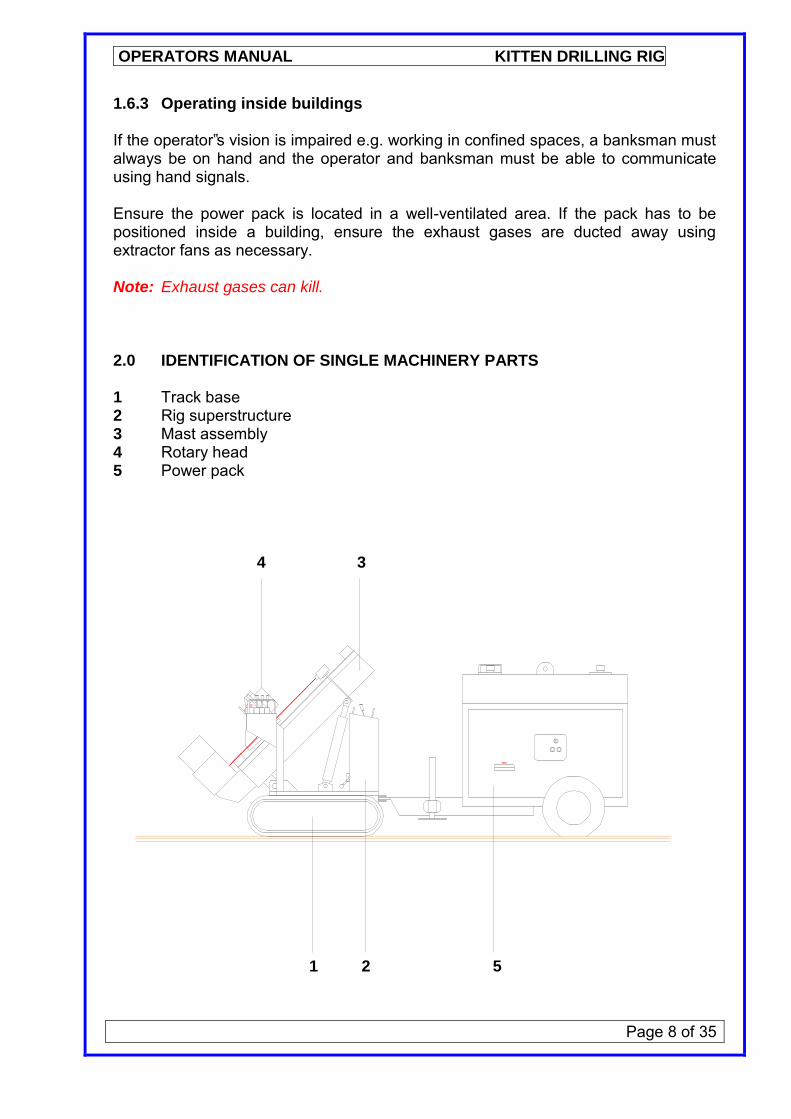
1.6.3 Operating inside buildings If the operator‟s vision is impaired e.g. working in confined spaces, a banksman must always be on hand and the operator and banksman must be able to communicate using hand signals. Ensure the power pack is located in a well-ventilated area. If the pack has to be positioned inside a building, ensure the exhaust gases are ducted away using extractor fans as necessary. Note: Exhaust gases can kill. 2.0 IDENTIFICATION OF SINGLE MACHINERY PARTS 1 Track base 2 Rig superstructure 3 Mast assembly 4 Rotary head 5 Power pack 4 3 1 2 5
OPERATORS MANUAL KITTEN DRILLING RIG
Page 9 of 35
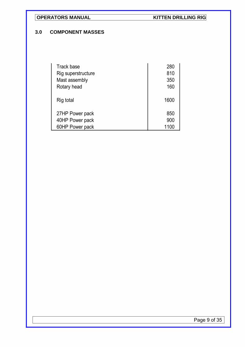
3.0 COMPONENT MASSES
Track base 280Rig superstructure 810Mast assembly 350Rotary head 160
Rig total 1600
27HP Power pack 85040HP Power pack 90060HP Power pack 1100
OPERATORS MANUAL KITTEN DRILLING RIG
Page 10 of 35
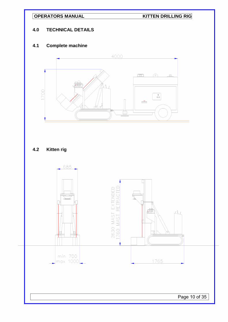
4.0 TECHNICAL DETAILS 4.1 Complete machine
4.2 Kitten rig
OPERATORS MANUAL KITTEN DRILLING RIG
Page 11 of 35
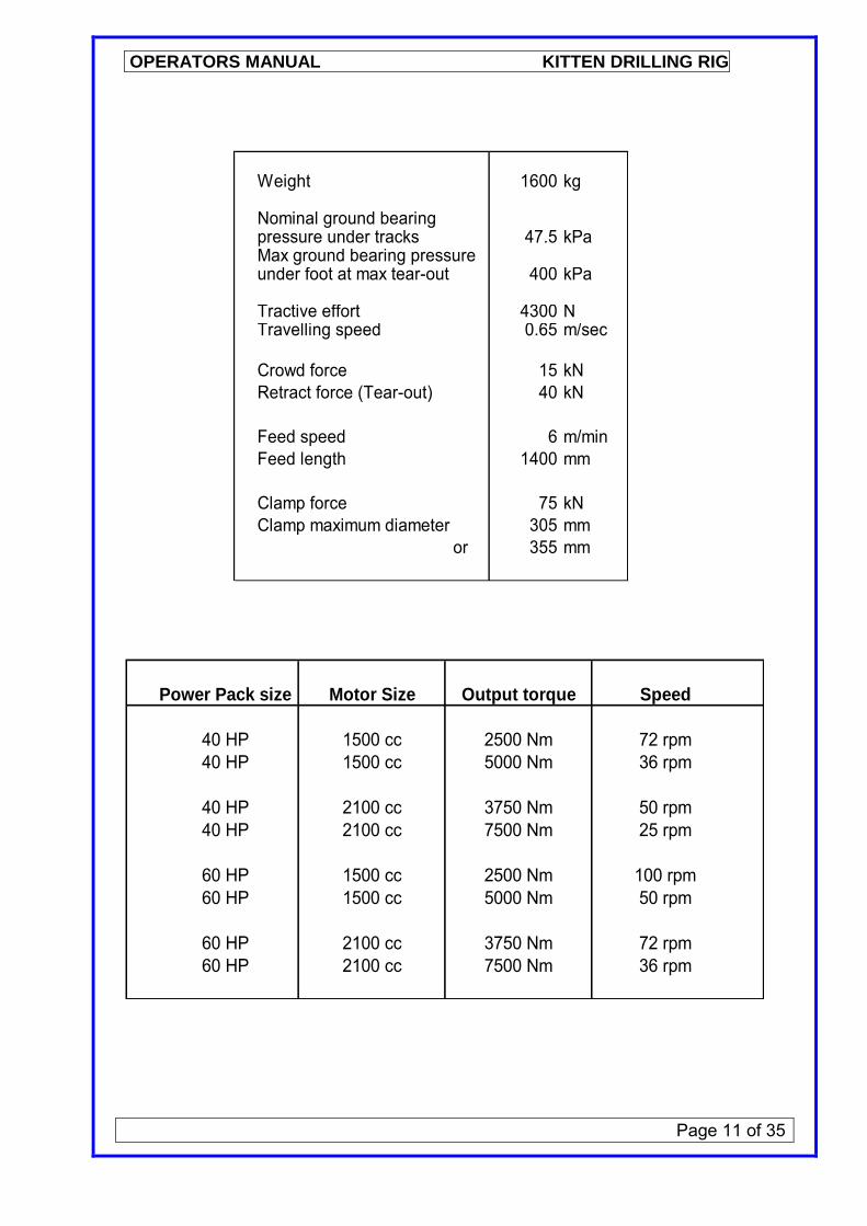
Power Pack size Motor Size Output torque Speed
40 HP 1500 cc 2500 Nm 72 rpm40 HP 1500 cc 5000 Nm 36 rpm
40 HP 2100 cc 3750 Nm 50 rpm40 HP 2100 cc 7500 Nm 25 rpm
60 HP 1500 cc 2500 Nm 100 rpm60 HP 1500 cc 5000 Nm 50 rpm
60 HP 2100 cc 3750 Nm 72 rpm60 HP 2100 cc 7500 Nm 36 rpm
Weight 1600 kg
Nominal ground bearingpressure under tracks 47.5 kPaMax ground bearing pressureunder foot at max tear-out 400 kPa
Tractive effort 4300 NTravelling speed 0.65 m/sec
Crowd force 15 kNRetract force (Tear-out) 40 kN
Feed speed 6 m/minFeed length 1400 mm
Clamp force 75 kNClamp maximum diameter 305 mm or 355 mm
OPERATORS MANUAL KITTEN DRILLING RIG
Page 12 of 35
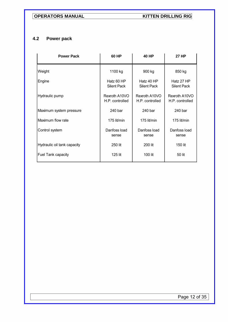
4.2 Power pack
Power Pack 60 HP 40 HP 27 HP
Weight 1100 kg 900 kg 850 kg
Engine Hatz 60 HP Hatz 40 HP Hatz 27 HPSilent Pack Silent Pack Silent Pack
Hydraulic pump Rexroth A10VO Rexroth A10VO Rexroth A10VOH.P. controlled H.P. controlled H.P. controlled
Maximum system pressure 240 bar 240 bar 240 bar
Maximum flow rate 175 lit/min 175 lit/min 175 lit/min
Control system Danfoss load Danfoss load Danfoss loadsense sense sense
Hydraulic oil tank capacity 250 lit 200 lit 150 lit
Fuel Tank capacity 125 lit 100 lit 50 lit

OPERATORS MANUAL KITTEN DRILLING RIG
Page 13 of 35
5.0 MACHINE CONTROLS 5.1 Power pack control panel

OPERATORS MANUAL KITTEN DRILLING RIG
Page 14 of 35
5.2 Kitten rig positioning control panel 1 2 3 4 5 6 7 8 5.3 Kitten rig drilling control panel 9 10 11
OPERATORS MANUAL KITTEN DRILLING RIG
Page 15 of 35
5.4 Power pack daily checks Before starting the engine at the beginning of the shift, carry out the following checks: Ensure the power pack is level and correct if necessary. Check hydraulic oil level and replenish with the recommended oil as necessary. Check the engine oil level and replenish with the recommended oil as necessary. Check the hoses and couplings for signs of leaks and rectify before starting the power pack. Check battery electrolyte level and top up with distilled water as required. Check aglomerator for water and drain as necessary. At the end of the shift, top up the fuel tank with gas oil to prevent condensation build-up in the fuel tank. 5.5 Kitten rig daily check Grease pivots (2points) and pulleys (2points) weekly. Grease rose joints (4 points) weekly. Check safety devices for correct operation and rectify any faults before commencing the shift. Check all bolts in the rotary head drive flange and tighten as necessary to the correct torque settings. Check hydraulic filter tell-tale for blockage. 5.6 Starting the machine Carry out the power pack and Kitten rig daily checks (5.4 & 5.5 above). Ensure that all the operating levers are in the neutral position. Insert the ignition key (5.1 above) and turn the key fully clockwise until the engine fires. Allow the engine to warm up for a few minutes before operating the machine. Note: never attempt to start the machine without all the hoses being properly connected to both Kitten rig and power pack.

OPERATORS MANUAL KITTEN DRILLING RIG
Page 16 of 35
5.7 Stopping the machine Ensure that all the operating levers are returned to the neutral position. Allow the engine to run at „idle‟ for approximately five minutes. Turn the ignition key fully anti-clockwise to stop the engine and remove the key. Note:- Only use the emergency stop buttons to switch off the engine in the event of an emergency. 5.8 Positions of emergency stops Trip wire emergency stops are provided at the front of the machine which allow the banksman to stop the machine. Push-button emergency stops are provided at both operating control panels to allow the rig driver to stop the machine. A push-button emergency stop is provided on the power pack to cover emergencies when the pack is positioned at a remote location.

OPERATORS MANUAL KITTEN DRILLING RIG
Page 17 of 35
6.0 RIGGING THE MACHINE 6.1 Connecting the hoses Note: the hose couplings are handed to ensure correct connection. Note: Towing hoses of approximately 1.5m length and operating hoses of 25m length are supplied with the machine. The two sets of hoses must not be connected in series or excessive pressure drops through the couplings may result. If hoses longer than 25m are required, Unwin Hydraulic Engineering Ltd. must be consulted. Ensure the power pack is turned off and the key is removed from the ignition. Inspect all hoses for exposed and damaged braiding or other signs of damage and reject as necessary. Taking one of the 3/4” hoses, clean the faces of the 3/4” female coupling on the power pack and the 3/4” male coupling on the hose with a clean, lint-free cloth. Inspect the locking groove on the male coupling for wear and replace as necessary. Connect the hose to the power pack and turn the locking ring (see note on page 18) on the coupling to ensure it has engaged correctly. Fully uncoil the hose leaving the female end close to the Kitten rig. Take the other 3/4” hose; clean the faces of the 3/4” male coupling on the power pack and the 3/4” female coupling on the hose with a clean, lint-free cloth. Inspect the locking groove on the male coupling for wear and replace as necessary. Connect the hose to the power pack and turn the locking ring on the coupling to ensure it has engaged correctly. Fully uncoil the hose leaving the male end close to the Kitten rig. Repeat the above procedure for the 1/2” hoses. Taking the same precautions as above, connect the remaining hose ends to the Kitten rig. Check the condition of the hoses daily before starting the shift.

OPERATORS MANUAL KITTEN DRILLING RIG
Page 18 of 35
Note: The hoses will normally be full of oil and temperature variation may cause a small pressure build-up, which will make connection difficult. Remedy: Have a container on hand to collect any spilt oil. Using the correct sized spanners, loosen the quick release coupling at one end of the hose and allow a small amount of oil to escape into the container to dissipate the pressure. Note: A check valve is fitted near the return line quick-release coupling on the Kitten rig. Oil escaping from this valve indicates a higher than normal return line pressure level and may be caused by the quick-release couplings not seating properly or by operating with hoses longer than the standard length supplied. 6.2 Extending the tracks to the operating position Ensure that the rig is standing on firm level ground. Set the mast to the vertical position (levers 5 & 6). Set the mast foot to the fully down position (lever 4). Set the track extend/retract lever (5.0 above) to the extend/retract position. Standing BEHIND the machine, set the tracks to the extended position using lever 7. Return the track extend/retract lever (5.0 above) to the tracking position. 6.3 Setting the rig to the travelling position Ensure that all the drill rods/augers have been removed and move the rotary head to the bottom of the mast (lever 2). Retract the mast foot (lever 4). Rake the mast backwards to the fully retracted position (levers 5 & 6). The rig is now in the travelling position.
OPERATORS MANUAL KITTEN DRILLING RIG
Page 19 of 35
7.0 LOADING AND UNLOADING THE KITTEN RIG FOR TRANSPORT Note: when tracking the rig, the operator should stand to the side of the machine and face the direction of travel. He should operate the travel levers with the hand closest to the machine by gripping the lever protection guard with the fingers and rocking the levers with the palm of the hand. 7.1 Trailer requirements Trailer type Beavertail Capacity 3500 kg Minimum flat bed length 3600 mm Minimum flat bed width 1800 mm Electric drive recovery winch 1 Tonne line pull 7.2 Preparing the trailer for loading Park the trailer on firm level ground allowing at least 5m clear space behind it and ensure the handbrake is correctly applied. Note: If the trailer is to be parted from the towing vehicle, ensure the jockey wheel is lowered and correctly secured. Lower and secure the jack legs at the rear of the trailer. Position the loading ramp(s) at the back of the trailer. 7.3 Loading the kitten rig onto the trailer 7.3.1 Loading Kitten rig only Ensure the working hoses are correctly connected (6.1 above). Carry out the power pack daily checks (5.4 above). Carry out the Kitten rig daily checks (5.5 above). Lower the rotary head to the bottom of the mast. Rake the mast back to its full extent. Attach the recovery winch line to the guide bush with the shackle supplied
OPERATORS MANUAL KITTEN DRILLING RIG
Page 20 of 35
Note: The recovery winch is provided for additional safety in case the rig slides on wet and/or muddy ramps. It is NOT intended to pull the rig up the ramps. Instruct the banksman to gather up the hoses and keep them clear of the tracks during the following rig moves. Line the Kitten rig up with the trailer ramp (lever 7 & 8) such that the rig is straight and in line with the centre of the trailer. Track the rig slowly up the ramp and onto the flat bed of the trailer taking care to recover the winch rope at the same pace as the rig is moving. Note: for reasons of safety and ease of operation, keep the rig moving slowly as the tracks pivot over the point of balance at the top of the ramp. Set the mast vertical (levers 5 & 6) and lower the mast foot (lever 4). Secure the rig to the trailer using appropriate ratchet-type securing straps. Stow the ramp(s) and raise and stow the rear jacklegs. 7.3.2 Loading Kitten rig and power pack together Carry out the power pack daily checks (5.4 above). Carry out the Kitten rig daily checks (5.5 above). Lower the rotary head to the bottom of the mast (lever 2). Rake the mast back to its full extent (levers 5 & 6). Reverse the Kitten rig to the power pack (levers 7 & 8) and couple the draw bar on the pack to the towing eye on the rig. Remove the working hoses (10.2 below) and connect the towing hoses (6.1 above). Attach the recovery winch line to the guide bush with the shackle supplied Note: The recovery winch is provided for additional safety in case the rig slides on wet and/or muddy ramps. It is NOT intended to pull the rig up the ramps. Line the Kitten rig up with the trailer ramp such that the rig and power pack are straight and in line with the centre of the trailer. Track the rig slowly up the ramp and onto the flat bed of the trailer taking care to recover the winch rope at the same pace as the rig is moving.
OPERATORS MANUAL KITTEN DRILLING RIG
Page 21 of 35
Note: for reasons of safety and ease of operation, keep the rig moving slowly as the tracks pivot over the point of balance at the top of the ramp. Centralise the rig and power pack on the trailer. Set the mast to the vertical position and lower the mast foot. Secure the rig and power pack to the trailer using appropriate ratchet-type securing straps. Stow the ramp(s) and raise and stow the rear jacklegs. 7.4 Preparing the trailer for unloading Park the trailer on firm level ground allowing at least 5m clear space behind it and ensure the handbrake is correctly applied. Note: If the trailer is to be parted from the towing vehicle, ensure the jockey wheel is lowered and correctly secured. Lower and secure the jack legs at the rear of the trailer. Position the loading ramp(s) at the back of the trailer. Release the securing straps. Connect the recovery winch to the guide bush using the shackle supplied. Note: The recovery winch is provided for additional safety in case the rig should slip on wet and/or muddy ramps. It is NOT intended to lower the machine from the trailer. 7.5 Unloading the Kitten rig from the trailer 7.5.1 Unloading Kitten rig only Ensure the working hoses are correctly connected (6.1 above). Carry out the power pack daily checks (5.4 above). Carry out the Kitten rig daily checks (5.5 above). Fully raise the mast foot. Ensure the rotary head is at the bottom of the mast. Rake the mast back to its full extent.
OPERATORS MANUAL KITTEN DRILLING RIG
Page 22 of 35
Instruct the banksman to gather up the hoses and keep them clear of the tracks during the following rig moves. Track the rig slowly, straight backwards down the ramp and onto the ground, taking care to pay out the recovery winch rope at the same pace as the rig is moving. Note: for reasons of safety and ease of operation, keep the rig moving slowly as the tracks pivot over the point of balance at the top of the ramp. Stow the trailer ramp(s) and raise and stow the rear jacklegs. Track the rig to a safe parking area 7.5.2 Unloading Kitten rig and power pack Ensure the towing hoses are correctly connected (6.1 above). Carry out the power pack daily checks (5.4 above). Carry out the Kitten rig daily checks (5.5 above). Fully raise the mast foot. Ensure the rotary head is at the bottom of the mast. Rake the mast back to its full extent. Track the rig and pack slowly, straight backwards down the ramp and onto the ground, taking care to pay out the recovery winch rope at the same pace as the rig is moving. Note: for reasons of safety and ease of operation, keep the rig moving slowly as the tracks pivot over the point of balance at the top of the ramp. Stow the trailer ramp(s) and raise and stow the rear jacklegs. Track the rig to a safe parking area.

OPERATORS MANUAL KITTEN DRILLING RIG
Page 23 of 35
8.0 MOVING THE MACHINE ON SITE 8.1 General When tracking the machine across site, face the direction of travel and operate the track control levers with one hand i.e. use the left hand when tracking forwards and the right hand when tracking backwards. Note: To retain control when tracking on undulating ground, hold the lever guard bar with the fingers and operate the tracking levers with the palm of the hand rocking the hand to and fro to steer. When moving the machine, the rotary head must always be lowered to the bottom of the mast and the mast fully raked back towards the control panel. Ensure all personnel are standing clear of the machine. It is the banksman‟s responsibility to keep the hoses between the power pack and the rig free so they do not get „snagged‟ or „tracked over‟ by the rig. Before tracking the rig across bridges, walkways, scaffolding or similar, obtain written instruction from the main contractor confirming that the structure will safely carry the weight of the machine. 8.2 Normal operating zones Rods, augers and casing sections should be loaded from within the marked zone, keeping the operators position clear.
OPERATORS MANUAL KITTEN DRILLING RIG
Page 24 of 35
8.3 Travelling on slopes and ramps Do not attempt to track the machine across the face of a slope – the machine must always be tracked straight up or straight down a slope. Note: Do not attempt to travel on slopes steeper than 1 in 6 8.4 Operating on slopes Do not operate the machine on a slope greater than 3 in any direction. 8.5 Drilling at an angle Do not operate the machine with the mast at an angle greater than 5 in any direction from the vertical position( determined by using a inclinometer).
OPERATORS MANUAL KITTEN DRILLING RIG
Page 25 of 35
9.0 DRILLING 9.1 Auger drilling Note: this section assumes the use of fully (continuous) flighted, solid hexagon drive, pin jointed augers of 1m effective length. Check that all auger flights, hexagon drives and cutting heads are in good condition. Do not use fish-tail bits or other cutting heads that are worn below the nominal diameter otherwise excessive wear of the auger flights will ensue. Any auger flights that are worn by more than 5mm should be rejected and returned for repair. Ensure the correct hexagon drive sub is fitted to the rotary head. Connect the fish-tail bit or other cutting head to the lead auger and fit the locking pin taking care to position the tail of the securing pin away from the cutting edge such that spoil flowing over the tail presses it towards the auger stem. (Fitting the pin in the reverse direction will allow spoil to get under the tail and loosen the spring) Lift the rotary head as high as possible (lever 2 or 11) and place the lead auger into the guide bush. Lower the rotary head and engage the rotary head drive hexagon in the top of the lead auger. Correct the alignment of the drive hexagon as necessary by rotating the rotary head (lever 1 or 9). Using a combination of rotation and feed, drill the lead auger into the ground ensuring spoil is flighted up over the guide bush. Note: excessive feed will cause the rotary head to stall and may, under extreme conditions cause the rig to skid sideways around the auger. When the rotary head reaches the bottom of the mast, disconnect the locking pin below the rotary head and lift the head as high as possible. Add another auger section taking care to align the flights correctly and fit the locking pins such that the tails of the pins point away from the direction of rotation (as above). Continue to drill down and add augers until the required depth is reached. Allow the auger to rotate for a short while.

OPERATORS MANUAL KITTEN DRILLING RIG
Page 26 of 35
9.2 Auger withdrawal During withdrawal, the auger should be kept rotating forwards (lever 1 or 9) while the rotary head is lifted (lever 2 or 11). Lift the string until the top auger section is well clear of the guide bush. Stop rotating and close the clamp (lever 3 or 10) to prevent the remainder of the string dropping back down the hole. Remove both the top and bottom locking pins from the top auger section. While the banksman holds the auger section, lift the rotary head away to allow the banksman to remove the auger and stack it away from the machine. Bring the head back down and connect it to the next auger section taking care to ensure the locking pin is securely fitted. Release the clamp and rotate the auger forwards while lifting the next section of auger above the guide bush. Repeat the process until the auger string is fully removed. 9.3 Auger and case drilling Note: this section assumes the use of fully (continuous) flighted, solid hexagon drive, pin jointed augers and left hand threaded casings of 1m effective length. Check that all auger flights, hexagon drives and cutting heads are in good condition. Do not use fish-tail bits or other cutting heads that are worn below the nominal diameter otherwise excessive wear of the auger flights will ensue. Any auger flights that are worn by more than 5mm should be rejected and returned for repair. Ensure the correct hexagon drive sub is fitted to the rotary head. Check the lead casing cutting shoe and replace as necessary. Check all casing threads for wear or damage and reject for repair accordingly. Connect the fish-tail bit or other cutting head to the lead auger and fit the locking pin taking care to position the tail of the securing pin away from the cutting edge such that spoil flowing over the tail presses it towards the auger stem. (Fitting the pin in the reverse direction will allow spoil to get under the tail and loosen the spring) Lift the rotary head as high as possible (lever 2 or 11) and place the lead auger in the guide bush. Lower the rotary head and engage the rotary head drive hexagon in the top of the lead auger. Correct the alignment of the drive hexagon as necessary by rotating the rotary head (lever 1 or 9).
OPERATORS MANUAL KITTEN DRILLING RIG
Page 27 of 35
Using a combination of rotation and feed, drill the lead auger into the ground ensuring spoil is flighted up over the guide bush. Note: excessive feed will cause the rotary head to stall stall and may, under extreme conditions cause the rig to skid sideways around the auger. When the rotary head reaches the bottom of the mast, withdraw the auger while continuing to rotate it in the drilling direction (clockwise) and when it is clear of the guide bush, remove it from the machine. Lift the lead casing into the guide bush, clean and lubricate the threads on both casing and rotary head and connect the casing to the rotary head. Using a combination of rotation and feed, „screw‟ the lead casing into the ground until the threads are close to the guide bush. Clamp the lead casing in the guide bush (lever 3 or 10). Enter the lead auger into the top of the casing and lower it to the bottom of the hole. Add the next auger section, ensuring that the tails on the locking pins are facing in the correct direction (see section 9.1 above) and drill down until the rotary head is just clear of the guide bush. Disconnect the rotary head from the auger and lift the next section of casing into position. Clean and lubricate the casing and rotary head threads and connect the rotary head to the casing. Leaving the augers inside the casing, release the clamp and „screw‟ the casing down into the ground until the top threads are close to the guide bush. Clamp the casing and repeat the procedure until the casing is installed to the required depth. Note: it is often advantageous to lubricate the casing as it is installed by pouring a bucket of water around the outside of the casing as it is rotated. Carry on adding augers as in section 9.1 above until the required depth is reached. 9.4 Auger withdrawal from casing Removal of the augers requires the use of an auger plate to stop the auger dropping down the hole as the locking pins are removed. This auger plate should be rested on the top of the casing as each auger is disconnected. Auger withdrawal is otherwise carried out as in 9.2 above.

OPERATORS MANUAL KITTEN DRILLING RIG
Page 28 of 35
9.5 Casing withdrawal After any reinforcement and concrete have been placed, bring the rotary head down, clean and lubricate casing and rotary head threads and connect the rotary head to the top of the casing. Release the clamp (lever 3 or 10). Rotate the casing anti-clockwise (lever 1 or 9) and lift the casing with the feed (lever 2 or 11). When the next casing joint is brought through the clamp, stop rotation and clamp the casing. Rotate the rotary head clockwise and break the casing joint at the clamp (do not fully undo the joint). The banksman must then attach the casing tongs supplied to the lower end of the top casing section in the correct orientation. Slowly rotate the head until the casing tongs bear on the clamp housing. Ensure the banksman is standing clear in case the tongs slip and rotate the head to „break‟ the connection between the top casing section and the rotary head. While the banksman supports the casing section, fully unscrew the rotary head from the casing and lift it as high as possible. Allow the banksman to remove the casing section using chain tongs to unscrew it if necessary and stack it away from the machine. Repeat until the whole casing has been removed. 9.6 Down-hole hammer drilling Ensure the correct sub and shock absorber are fitted to the rotary head. Lift the rotary head as high as possible (lever 2 or 11). Remove the protective cap from the hammer and pour approximately half a pint of approved oil into the hammer. Coat the threads on both hammer and rotary head lightly with approved grease and attach the hammer to the rotary head. Lift the hammer and insert the drill bit into the hammer, taking care to ensure it moves freely in the hammer. Note: when operating the machine with a down-hole hammer, it is essential for the operator and banksman to wear ear defenders and advisable to wear protective goggles and face mask particularly when drilling in restricted access conditions. Enter the hammer into the guide bush and turn the air supply to the hammer on. Rotate the hammer slowly (lever 1 or 9) and gradually feed the bit into the ground.

OPERATORS MANUAL KITTEN DRILLING RIG
Page 29 of 35
Note: as the bit is pushed back into the hammer body, the hammer will start to operate. When solid ground is encountered, adjust the feed and rotation rates to obtain the optimum rate of drilling. Continue drilling until the rotary head approaches the guide bush and turn off the air supply to the hammer. Stop the rotation to allow the banksman to fit the correct spanner to the drill rod. Slowly reverse the rotary head until the spanner engages on the guide bush. Allow the banksman to stand clear and then reverse the rotary head to „break‟ the joint. Fully unscrew the head from the rod while lightly reversing the feed to lift the head and avoid damaging the thread. Once clear, lift the rotary head as high as possible to allow the banksman to remove the rod spanner. Apply a light smear of grease to both threads and introduce the next drill rod, screwing it together as far as possible by hand. Bring the rotary head down and enter the head sub unto the top of the new rod. Rotate the rotary head slowly until the threads fully engage, turn the air supply back on and recommence drilling. Repeat until the required depth is reached. 9.7 Down-hole hammer withdrawal To remove the equipment from the hole, reverse the feed and lift the string until the top drill rod is completely clear of the guide bush. Turn off the air supply to the hammer and allow the banksman to fit a spanner to the top flats of the drill rod still in the hole. Note: this spanner will also support the string when the top rod is disconnected. Allow the banksman to stand clear and slowly reverse the rotary head until the spanner engages on the flats provides on the guide bush. Reverse the rotary head to „break‟ the joint but do not fully undo it. Allow the banksman to fit another spanner to the flats on the exposed drill rod and slowly reverse the rotary head until the spanner engages on the mast slide. Allow the banksman to stand clear and reverse the rotary head to „break‟ the joint. Fully unscrew the head from the rod while lightly reversing the feed to lift the head and avoid damaging the thread. Once clear, lift the rotary head as high as possible to allow the banksman to remove the spanner and drill rod. Bring the rotary head down and enter the head sub unto the top of the exposed rod. Rotate the rotary head slowly until the threads fully engage and the spanner rotates to the opposite stop in the guide bush. Allow the banksman to stand clear and fully tighten the joint. Reverse the feed and rotate the head forwards if necessary to free the spanner. Allow the banksman to remove the spanner and lift the head until the next joint emerges through the guide bush. Repeat the above operations until just the hammer is left in the machine.

OPERATORS MANUAL KITTEN DRILLING RIG
Page 30 of 35
Cover the bore hole and move the rig to the next location. 9.8 Hollow stem auger drilling Note: this section assumes the use of fully (continuous) flighted, augers of 1m effective length, connected by rope threads. Fit the correct drive sub to the rotary head. Check that all auger flights, rope threads and cutting heads are in good condition. Do not use cutting heads that are worn below the nominal diameter otherwise excessive wear of the auger flights will ensue. Any auger flights that are worn by more than 5mm should be rejected and returned for repair. Fit the blanking plug to the lead auger. Lift the rotary head as high as possible (lever 2 or 11) and place the lead auger in the guide bush. Lower the rotary head, engage the rotary head drive sub into the top of the lead auger and engage the drive pin. Using a combination of rotation (lever 1 or 9) and feed, drill the lead auger into the ground ensuring spoil is flighted up over the guide bush. Note: slow rotation or excessive feed will cause the rotary head to stall. When the rotary head reaches the bottom of the mast, disconnect the drive pin below the rotary head and lift the head as high as possible. Allow the banksman to lift in the next auger section into position, lower the rotary head and engage the sub into the top of the auger. Fit the drive pin, apply a light smear of the approved grease to the exposed thread and screw the auger joint together. Continue to drill down and add augers in the same manner until the required depth is reached. Allow the auger to rotate for a short while.

OPERATORS MANUAL KITTEN DRILLING RIG
Page 31 of 35
9.9 Hollow stem auger withdrawal Disconnect the drive pin and lift the rotary head to the top of the mast (lever 2 or 11). Remove the blanking plug, introduce the grout supply hose and fill the auger stem with grout. Remove the grout supply hose. Bring the rotary head back down and engage the drive sub into the top of the exposed auger. Fit the drive pin and, while slowly rotating the auger forwards, (lever 1 or 9) engage the feed to withdraw the auger until the next joint is exposed. Engage the clamp (lever 3 or 10) and unscrew the auger joint by reversing the rotary head while applying a light reverse feed. While the banksman supports the top auger section, remove the drive pin and lift the rotary head as high as possible. Allow the banksman to remove the auger section and introduce the grout hose and refill the auger stem. Repeat until the hole is completely filled. Note: it may be necessary when removing the last three or four auger sections, to stop after having withdrawn half of the auger section and refill the auger stem with grout. Move the rig away from the hole and introduce the reinforcing cage.

OPERATORS MANUAL KITTEN DRILLING RIG
Page 32 of 35
10.0 DE-RIGGING THE MACHINE 10.1 General Remove all drill rods/augers. Disconnect any water/air flushing hoses. Clean all mud off the machine particularly from the track assemblies. Lower the rotary head to the bottom of the mast (lever 2). Retract the foot cylinders (lever 4). Rake the mast fully back over the control panel (levers 5 & 6). Switch off the power pack (section 5.7 above). 10.2 Disconnecting the hoses Ensure the power pack is turned off (section 5.7 above). Inspect all hoses and couplings for leaks and replace as necessary. Starting with one of the 3/4” hoses at the power pack end, turn the locking ring until the notch is aligned with the steel ball and pull the locking ring back to separate the coupling. Follow the hose back to the Kitten rig end, turn the locking ring until the notch is aligned with the steel ball and pull the locking ring back to separate the coupling. Coil the hose up and connect the two ends together. Repeat the procedure for the other three hoses.

OPERATORS MANUAL KITTEN DRILLING RIG
Page 33 of 35
HYDRAULIC CIRCUIT Note:- The accumulator (item 39) fitted in the casing drain line at the back of the Kitten rig is pre-charged to only 2 bar and its purpose is to absorb pressure pulses that arise from time to time.

OPERATORS MANUAL KITTEN DRILLING RIG
Page 34 of 35
APPENDIX 3
Routine Maintenance Note:- for routine engine maintenance, refer to the Hatz engine manual
supplied with the machine, with the exception of the oil and filter change interval which is recommended below.
1 Engine oil
Engine oil and filter change interval 200 Hours 2 Hydraulic oil
Hydraulic oil change interval 1000 Hours 3 Hydraulic oil filters
Main return-line canister 200 Hours
Pilot filter 1000 Hours
Suction filter Inspect every 1000 Hours
4 Pressure filter on rig
This filter is fitted with a “pop-out” indicator button. The filter must be changed on indication but only when the hydraulic oil has reached operating temperature since cold oil will often trip the indicator.
Normal replacement interval 500 Hours
OPERATORS MANUAL KITTEN DRILLING RIG
Page 35 of 35
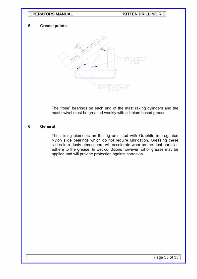
5 Grease points
The “rose” bearings on each end of the mast raking cylinders and the mast swivel must be greased weekly with a lithium based grease.
6 General
The sliding elements on the rig are fitted with Graphite impregnated Nylon slide bearings which do not require lubrication. Greasing these slides in a dusty atmosphere will accelerate wear as the dust particles adhere to the grease. In wet conditions however, oil or grease may be applied and will provide protection against corrosion.