operator’s manual - intermodal concepts - sea · of the refrigeration system, you contact your...
TRANSCRIPT


MANUALOPERATOR’S
Supra 550, 650,750, 850 & 950
TRUCKREFRIGERATION
UNITS

CONTENTS
Page
Unit Identification 2. . . . . . . . . . . . . . . . . . . . . . . . . .
Safety 3. . . . . . . . . . . . . . . . . . . . . . . . . . . . . . . . . . . .
Pre-Trip Inspection 4. . . . . . . . . . . . . . . . . . . . . . . . .
Unit Operation 6. . . . . . . . . . . . . . . . . . . . . . . . . . . .
Starting the Unit -- Road Operation 6. . . . . . . . . . .
Starting the Unit -- Standby Operation 7. . . . . . . .
Starting the Unit -- Manual Operation 8. . . . . . . . .
Pretrip Check 9. . . . . . . . . . . . . . . . . . . . . . . . . . . . .
Changing Setpoint 10. . . . . . . . . . . . . . . . . . . . . . . .
Start/Stop Operation 12. . . . . . . . . . . . . . . . . . . . . .
Continuous Run Operation 14. . . . . . . . . . . . . . . . .
Manual Defrost 15. . . . . . . . . . . . . . . . . . . . . . . . . . .
City Speed 16. . . . . . . . . . . . . . . . . . . . . . . . . . . . . . .
Function Change 17. . . . . . . . . . . . . . . . . . . . . . . . .
Unit Data 19. . . . . . . . . . . . . . . . . . . . . . . . . . . . . . . .
Alarm Display and Reset 21. . . . . . . . . . . . . . . . . .
Stopping Unit 23. . . . . . . . . . . . . . . . . . . . . . . . . . . .
Product Loading 24. . . . . . . . . . . . . . . . . . . . . . . . . .
Recommended Transport Temperatures 26. . . . .
Problems 27. . . . . . . . . . . . . . . . . . . . . . . . . . . . . . . .
Troubleshooting 28. . . . . . . . . . . . . . . . . . . . . . . . . .
Relay Board 30. . . . . . . . . . . . . . . . . . . . . . . . . . . . .
Unit Maintenance 32. . . . . . . . . . . . . . . . . . . . . . . . .
Unit Maintenance Schedule 34. . . . . . . . . . . . . . . .
Standby Operation Guidelines 39. . . . . . . . . . . . . .
Emergency Road Service 40. . . . . . . . . . . . . . . . . .

1
SUPRA OPERATOR’S MANUALThis guide has been prepared for the operator of Carrier Transicolddiesel truck refrigeration units. It contains basic instructions for thedaily operation of the refrigeration unit aswell as safety information,troubleshooting tips, and other information that will help you to de-liver the load in the best possible condition. Please take the time toread the information contained in this booklet and refer to it when-ever you have a question about the operation of your Carrier Tran-sicold Supra unit.
Your refrigeration unit has been engineered to provide long,trouble-free performance when it is properly operated and main-tained. The checks outlined in this guide will help to minimize over-the-road problems. In addition, a comprehensivemaintenancepro-gram will help to insure that the unit continues to operate reliably.Such a maintenance program will also help to control operatingcosts, increase the unit’s working life, and improve performance.
This guide is intended as an introduction to your unit and to providegeneral assistance when needed. More comprehensive informa-tion canbe found in theOperation andServiceManual for your unit.This manual can be obtained from your local Carrier Transicolddealer.
When having your unit serviced, be sure to specify genuineCarrierTransicold replacement parts for the highest quality and best reli-ability.
At Carrier Transicold, we are continually working to improve theproducts that we build for our customers. As a result, unit specifica-tions may change without notice.

2
UNIT IDENTIFICATION
Each Supra 50 Series unit is identified by a nameplate attached tothe frame near the accumulator. This nameplate identifies thecomplete model number of the unit, the serial number, therefrigerant charge and quantity, and the date the unit was placedin service.
If a problem occurs, please refer to the information on this plate,and make a note of the model and serial number before calling forassistance. This information will be needed when you contact atechnician or Carrier Transicold Service Engineer so that he or shemay properly assist you.
NAMEPLATE

3
SAFETY
Your Carrier Transicold refrigeration unit has been designed withthe safety of the operator in mind. During normal operation, allmoving parts are fully guarded to help prevent injury. During allpre-trip inspections, daily inspections, and problemtroubleshooting, you may be exposed to moving parts; please stayclear of all moving parts when the unit is in operation and when theunit main power switch is in the RUN position.
AUTO-START/STOPYour refrigeration unit is equipped with Auto-Start/Stop, a valuablefuel saving feature. When the unit is set for Auto-Start/Stopoperation it may start at any time and without warning. Whenperforming any check of the refrigeration unit (e.g., checking thebelts, checking the oil), make certain that the main power switch isin the OFF position.
ENGINE COOLANT
The engine is equipped with a pressurized cooling system. Undernormal operating conditions, the coolant in the engine and radiatoris under high pressure and is very hot. Contact with hot coolant cancause severe burns. Do not remove the cap from a hot radiator. Ifthe cap must be removed, do so very slowly in order to release thepressure without spray.
REFRIGERANTS
The refrigerant contained in the refrigeration system of your unitcan cause frostbite, severe burns, or blindness when in directcontact with the skin or eyes. For this reason, and because oflegislation regarding the handling of refrigerants during systemservice, we recommend that whenever your unit requires serviceof the refrigeration system, you contact your nearest CarrierTransicold authorized repair facility for service.
BATTERY
This unit utilizes a lead-acid type battery. The battery normallyvents small amounts of flammable hydrogen gas. Do not smokewhen checking the battery. A battery explosion can cause seriousphysical harm and/or blindness.

4
PRE-TRIP INSPECTION
The pre-trip inspection should be performed before picking up anyload. This inspection is essential to anticipate andhelpminimize thepossibility of “over-the-road” problems. These checks take only afew minutes.
1. Place the unit’s main switch in the STOP (0) position.
2. Fuel -- drain any water and impurities from the sump of therefrigeration unit fuel tank by opening thedrain-cock locatedonthe bottom of the tank (if so equipped). Close the valve whenonly pure fuel emerges. Check the fuel level in the tank,ensuring that the fuel supply is adequate for unit operation.Refuel if necessary.
3. Belts -- Check the belt tension by depressing the belt with yourthumb, near the center of the longest free run of each belt.Under moderate pressure each belt should deflectapproximately 6 mm to 13mm (1/4 inch to 1/2 inch). If the beltsdeflect more than this they should be tightened (loose beltsmay slip, generating heat and reducingbelt life). If the belts aretoo tight they should be loosened; tight belts can reducebearing life.
3. Battery -- on units equipped with serviceable batteries, the levelof the electrolyte in each of the cells should be checked. If thelevel is low, distilled water should be added to the correct level.Most units, however, are equippedwith low or no--maintenancebatteries. These should be inspected to ensure that theconnections are clean and tight, and the battery hold--downshould be checked for tightness.
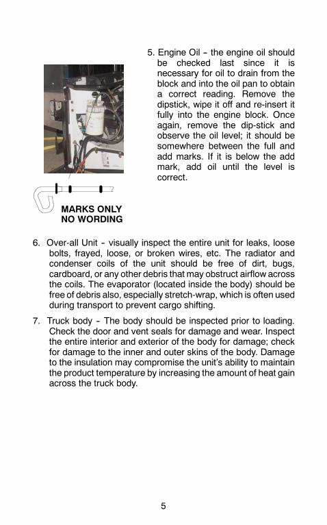
MARKS ONLYNO WORDING
5
5. Engine Oil -- the engine oil shouldbe checked last since it isnecessary for oil to drain from theblock and into the oil pan to obtaina correct reading. Remove thedipstick, wipe it off and re-insert itfully into the engine block. Onceagain, remove the dip-stick andobserve the oil level; it should besomewhere between the full andadd marks. If it is below the addmark, add oil until the level iscorrect.
6. Over-all Unit -- visually inspect the entire unit for leaks, loosebolts, frayed, loose, or broken wires, etc. The radiator andcondenser coils of the unit should be free of dirt, bugs,cardboard, or any other debris that may obstruct airflow acrossthe coils. The evaporator (located inside the body) should befree of debris also, especially stretch-wrap, which is often usedduring transport to prevent cargo shifting.
7. Truck body -- The body should be inspected prior to loading.Check the door and vent seals for damage and wear. Inspectthe entire interior and exterior of the body for damage; checkfor damage to the inner and outer skins of the body. Damageto the insulation may compromise the unit’s ability to maintainthe product temperature by increasing the amount of heat gainacross the truck body.
6
UNIT OPERATION
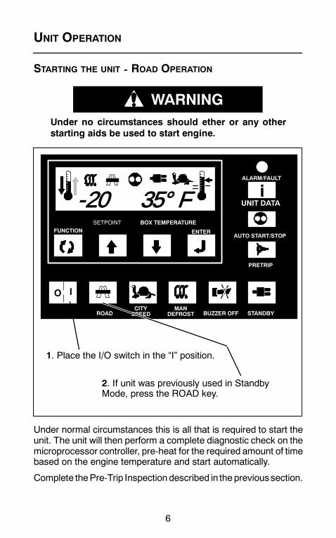
STARTING THE UNIT -- ROAD OPERATION
WARNINGUnder no circumstances should ether or any otherstarting aids be used to start engine.
BOX TEMPERATURE
AUTO START/STOP
I
UNIT DATA
PRETRIP
ALARM/FAULT
STANDBYBUZZER OFFMAN
DEFROSTCITYSPEEDROAD
FUNCTION ENTER
SETPOINT
O
i-20 35° F
1. Place the I/O switch in the “I” position.
2. If unit was previously used in StandbyMode, press the ROAD key.
Under normal circumstances this is all that is required to start theunit. The unit will then perform a complete diagnostic check on themicroprocessor controller, pre-heat for the required amount of timebased on the engine temperature and start automatically.
Complete thePre-Trip Inspection described in theprevioussection.
7
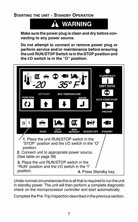
STARTING THE UNIT -- STANDBY OPERATION
WARNINGMake sure the power plug is clean and dry before con-necting to any power source.
Do not attempt to connect or remove power plug orperform service and/or maintenance before ensuringtheunit RUN/STOPSwitch is in theSTOPposition andthe I/O switch is in the “O” position.
BOX TEMPERATURE
AUTO START/STOP
I
UNIT DATA
PRETRIP
ALARM/FAULT
STANDBYBUZZER OFFMAN
DEFROSTCITYSPEEDROAD
FUNCTION ENTER
SETPOINT
O
i-20 35° F
2. Connect unit to appropriate power source.(See table on page 39)
4. Press Standby key.
1. Place the unit RUN/STOP switch in the“STOP” position and the I/O switch in the “O”position.
3. Place the unit RUN/STOP switch in the“RUN” position and the I/O switch in the “I”position.
Under normal circumstances this is all that is required to run theunitin standby power. The unit will then perform a complete diagnosticcheck on the microprocessor controller and start automatically.
Complete thePre-Trip Inspection described in theprevioussection.
8
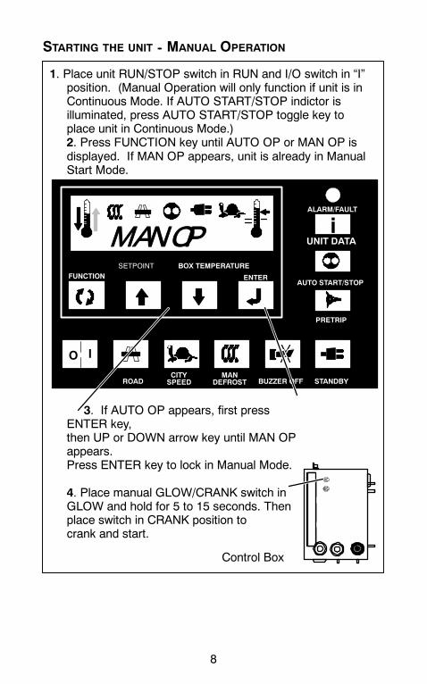
STARTING THE UNIT -- MANUAL OPERATION
BOX TEMPERATURE
AUTO START/STOP
I
UNIT DATA
PRETRIP
ALARM/FAULT
STANDBYBUZZER OFFMAN
DEFROSTCITYSPEEDROAD
FUNCTION ENTER
SETPOINT
O
iMAN OP
1. Place unit RUN/STOP switch in RUN and I/O switch in “I”position. (Manual Operation will only function if unit is inContinuous Mode. If AUTO START/STOP indictor isilluminated, press AUTO START/STOP toggle key toplace unit in Continuous Mode.)2. Press FUNCTION key until AUTO OP or MAN OP isdisplayed. If MAN OP appears, unit is already in ManualStart Mode.
3. If AUTO OP appears, first pressENTER key,then UP or DOWN arrow key until MAN OPappears.Press ENTER key to lock in Manual Mode.
4. Place manual GLOW/CRANK switch inGLOW and hold for 5 to 15 seconds. Thenplace switch in CRANK position tocrank and start.
Control Box
9
PRETRIP CHECK
BOX TEMPERATURE
AUTO START/STOP
I
UNIT DATA
PRETRIP
ALARM/FAULT
STANDBYBUZZER OFFMAN
DEFROSTCITYSPEEDROAD
FUNCTION ENTER
SETPOINT
O
iPPPP
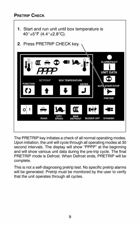
1. Start and run unit until box temperature is40_±5°F (4.4_±2.8°C).
2. Press PRETRIP CHECK key.
The PRETRIP key initiates a check of all normal operating modes.Upon initiation, the unit will cycle through all operating modes at 30second intervals. The display will show “PPPP” at the beginningand will show various unit data during the pre-trip cycle. The finalPRETRIP mode is Defrost. When Defrost ends, PRETRIP will becomplete.
This is not a self-diagnosing pretrip test. No specific pretrip alarmswill be generated. Pretrip must be monitored by the user to verifythat the unit operates through all cycles.
10
CHANGING SETPOINT
BOX TEMPERATURE
AUTO START/STOP
I
UNIT DATA
PRETRIP
ALARM/FAULT
STANDBYBUZZER OFFMAN
DEFROSTCITYSPEEDROAD
FUNCTION ENTER
SETPOINT
O
i
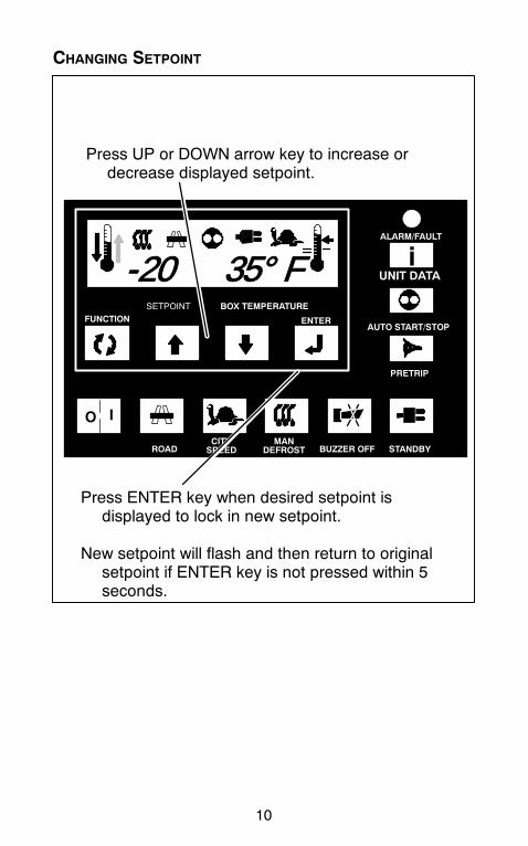
Press ENTER key when desired setpoint isdisplayed to lock in new setpoint.
New setpoint will flash and then return to originalsetpoint if ENTER key is not pressed within 5seconds.
Press UP or DOWN arrow key to increase ordecrease displayed setpoint.
-20 35° F

11
Setpoints of -22°F to +89°F (-30°C to +32°C) may be entered viathe keypad. The controller always retains the last entered setpointin memory. If no setpoint is in memory (i.e. on initial startup), thecontroller will lock out the run relay and flash “SP” on the left handdisplay until a valid setpoint is entered. The setpoint may bechanged up or down in 1° increments by pressing and releasingeither the UP ARROW or DOWN ARROW key.
You cannot change setpoint when unit is in Pretrip or when viewingUnit Data or Functional Parameters.
12
START/STOP OPERATION
BOX TEMPERATURE
AUTO START/STOP
I
UNIT DATA
PRETRIP
ALARM/FAULT
STANDBYBUZZER OFFMAN
DEFROSTCITYSPEEDROAD
FUNCTION ENTER
SETPOINT
O
i-20 35° F
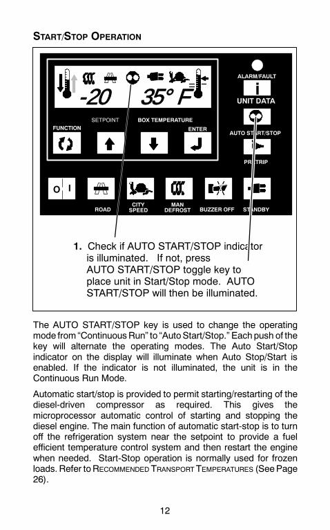
1. Check if AUTO START/STOP indicatoris illuminated. If not, pressAUTO START/STOP toggle key toplace unit in Start/Stop mode. AUTOSTART/STOP will then be illuminated.
The AUTO START/STOP key is used to change the operatingmode from “ContinuousRun” to “AutoStart/Stop.” Eachpush of thekey will alternate the operating modes. The Auto Start/Stopindicator on the display will illuminate when Auto Stop/Start isenabled. If the indicator is not illuminated, the unit is in theContinuous Run Mode.
Automatic start/stop is provided to permit starting/restarting of thediesel-driven compressor as required. This gives themicroprocessor automatic control of starting and stopping thediesel engine. The main function of automatic start-stop is to turnoff the refrigeration system near the setpoint to provide a fuelefficient temperature control system and then restart the enginewhen needed. Start-Stop operation is normally used for frozenloads. Refer toRECOMMENDED TRANSPORT TEMPERATURES (SeePage26).

13
Whenever the unit starts in Auto Start--Stop, it will run until:
SIt has run for the predetermined minimum run time.
SThe engine coolant temperature is above 122°F (50°C)
SThe box temperature is at setpoint.
The controller will not shut off the engine if the battery voltage is notsufficient to restart it. Battery voltage above approximately 13.4volts is required for shutdown. This varies depending on ambient.Look at battery voltage in data list to find out whether shutdownvoltage has been reached. If there is a “+” in front of the number,the voltage is enough to shutdown and restart. If only the numberappears, the voltage is still too low for shutdown.
The controller will restart the engine if any of the following criteriahave been met:
SBox temperature has changed by¦ 11°F (¦ 6.1°C)for setpointsin the perishable range and +11° F (+6.1°C) for setpoints in thefrozen range DURING minimum off time.
SBox temperature has moved away from setpoint by ¦3.6°F(2.0°C) AFTER minimum off time for setpoints in the perishablerange or +0.5°F (0.3°C) for setpoints in the frozen range.
SThe battery voltage drops below 12.2 Vdc Refer to Page 19 forunit data).
SThe engine coolant temperature drops below 34°F (1°C).
To start the unit inmanual startmode, theunit must be incontinuousrunmode and the Auto/Manual Start Operation function parameterset to “MAN OP” (FN10 OFF)
NOTEWhen configuration CNF11 is “ON” and setpoint is 32 to42_ F (0 to 5.5_C) the unit is locked into continuous run.The AUTO START/STOP key is disabled.
NOTEAuto Start-Stop operation may be tied to the setpoint ranges forfrozen and perishable loads and the AUTOSTART/STOP keymaybe locked out.

14
CONTINUOUS RUN OPERATION
BOX TEMPERATURE
AUTO START/STOP
I
UNIT DATA
PRETRIP
ALARM/FAULT
STANDBYBUZZER OFFMAN
DEFROSTCITYSPEEDROAD
FUNCTION ENTER
SETPOINT
O
i-20 35° F
1. Check if AUTO START/STOP indicatoris illuminated. If it is, pressAUTO START/STOP toggle key toplace unit in Continuous Run mode.AUTO START/STOP indicator will notbe illuminated.
In the Continuous Run mode, the diesel engine will runcontinuously providing constant air flow and temperature control tothe product. Continuous Run operation is normally used forperishable loads. Refer toRECOMMENDED TRANSPORT TEMPERATURES(See Page 26).
Continuous operation may be tied to the setpoint ranges for frozenand perishable loads and the AUTO START/STOP key may belocked out.
15
MANUAL DEFROST
BOX TEMPERATURE
AUTO START/STOP
I
UNIT DATA
PRETRIP
ALARM/FAULT
STANDBYBUZZER OFFMAN
DEFROSTCITYSPEEDROAD
FUNCTION ENTER
SETPOINT
O
i-20 35° F
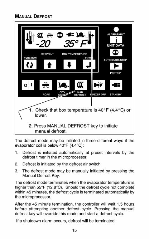
1. Check that box temperature is 40_F (4.4_C) orlower.
2. Press MANUAL DEFROST key to initiatemanual defrost.
The defrost mode may be initiated in three different ways if theevaporator coil is below 40°F (4.4°C):
1. Defrost is initiated automatically at preset intervals by thedefrost timer in the microprocessor.
2. Defrost is initiated by the defrost air switch.
3. The defrost mode may be manually initiated by pressing theManual Defrost Key.
The defrost mode terminates when the evaporator temperature ishigher than 55°F (12.8°C). Should the defrost cycle not completewithin 45 minutes, the defrost cycle is terminated automatically bythe microprocessor.
After the 45 minute termination, the controller will wait 1.5 hoursbefore attempting another defrost cycle. Pressing the manualdefrost key will override this mode and start a defrost cycle.
If a shutdown alarm occurs, defrost will be terminated.
16
CITY SPEED
BOX TEMPERATURE
AUTO START/STOP
I
UNIT DATA
PRETRIP
ALARM/FAULT
STANDBYBUZZER OFFMAN
DEFROSTCITYSPEEDROAD
FUNCTION ENTER
SETPOINT
O
i-20 35° F
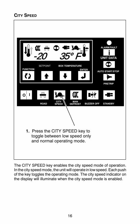
1. Press the CITY SPEED key totoggle between low speed onlyand normal operating mode.
The CITY SPEED key enables the city speed mode of operation.In the city speedmode, theunit will operate in lowspeed. Eachpushof the key toggles the operating mode. The city speed indicator onthe display will illuminate when the city speed mode is enabled.

17
FUNCTION CHANGE
BOX TEMPERATURE
AUTO START/STOP
I
UNIT DATA
PRETRIP
ALARM/FAULT
STANDBYBUZZER OFFMAN
DEFROSTCITYSPEEDROAD
FUNCTION ENTER
SETPOINT
O
i
1. Press FUNCTION key until Function tobe changed is displayed.
2. Press ENTER key.
3. Press either UP or DOWN ARROW key untildesired Function setting is displayed.
NOTE: Function changes will change operationof unit. NOTE: If configuration CNF11 is “ON”
functional parameters are locked.The ability to change any functionalparameters is disabled.
DEFR 12.0H
TheFunctionParameters control selectedoperating features of theunit. Whenmultiple choices are available, the display will show thefunction description on the left side with the corresponding functionchoice on the right side.
With a function parameter displayed, the data choice can bechanged by pressing ENTER then pressing either the up or downARROW keys. The displayed choice will then flash to indicate thatthe choice has not been entered. Depress the ENTER key to acti-vate the new choice. The display will stop flashing to indicate thatthe choice has been entered.

18
FUNCTION CHANGE
The following table has columns for Code and English displays.English is the default setting. Change Functional Parameter toCode to see Code display format.
Functional Parameters
CODE ENGLISH DATA
FN0 DEFR Defrost Interval
FN1 ON CITY SPD Low Speed
FN1 OFF HIGH SPD High Speed
FN2 OFF T Minimum Off-time
FN3 ON T On-time
FN4 a REMPROBE
Controlling Probe --Return Air
FN4 b SUPPROBE
Controlling Probe --Supply Air
FN5 DegreesF or C
Temperature Unit_C or _F
FN6 ON TIMESTRT Maximum Off-time 30 Min.
FN6 OFF TEMPSTRT
Temperature BasedRestarting
FN7 MOP STD Unloader Control
FN8 2SET N/A
FN9 3SET N/A
FN10 ON AUTO OP Auto Start Operation
FN10OFF
MAN OP Manual Start Operation
FN11 T RANGE Out-of-Range Tolerance
Code vs English = Code or English display format
Manual Glow Override = Normal or Add 30sec
Alarm RST = Alarm Reset RequiredAlarm CLR = No Alarm Active

19
UNIT DATA
BOX TEMPERATURE
AUTO START/STOP
I
UNIT DATA
PRETRIP
ALARM/FAULT
STANDBYBUZZER OFFMAN
DEFROSTCITYSPEEDROAD
FUNCTION ENTER
SETPOINT
O
isuct 25P
1.Press UNIT DATA key toscroll thru data list one itemat a time.
2. To scroll through the list faster, usethe UP or DOWN ARROW keys.
3. Data will display for 5 seconds
4. Press the ENTER key todisplay data for 30 seconds.
5. The display will revert back to the default displayif no keys are pressed for 5 seconds.
The UNIT DATA key can be used to display the microprocessorinput data values. The display will show the description of the inputon the left side with the actual data on the right side.

20
UNIT DATA CODESThe following table has columns for Code and English displays.English is the default setting. Change Functional Parameter toCode to see Code display format.
CODE ENGLISH DATACD1 SUCT Suction PressureCD2 ENG Engine HoursCD3 WT Engine TemperatureCD4 RAS Return Air Temperature*CD5 SAS Supply Air Temperature*CD6 REM Remote Air TemperatureCD7 ATS Ambient TemperatureCD8 EVP Future ExpansionCD9 CDT Discharge TemperatureCD10 BATT Battery VoltageCD11 SBY Standby HoursCD12 MOD V Future ExpansionCD13 REV Software RevisionCD14 SERL Serial Number LowCD15 SERU Serial Number UpperCD16 2RA N/ACD17 3RA N/ACD18 MHR1 Maintenance Hour Meter 1CD19 MHR2 Maintenance Hour Meter 2CD20 SON Switch On Hour Meter
* Codes 5 & 6 are variable. SAS is displayed whenthe SUP Probe Function is selected. REM is dis-played when the REM Probe Function is selected.

21
ALARM DISPLAY & RESET
ALARM DISPLAY
When fault light is on, normal display of Setpoint /Boxtemperature alternates with alarm display. Check display foralarm message.
ALARM RESET
BOX TEMPERATURE
AUTO START/STOP
I
UNIT DATA
PRETRIP
ALARM/FAULT
STANDBYBUZZER OFFMAN
DEFROSTCITYSPEEDROAD
FUNCTION ENTER
SETPOINT
O
iENG OIL
3. Press ENTER to clear alarm. ALARMCLR will be displayed. (Unit will restart ifalarm condition has been corrected andunit is in Start/Stop or Auto OP).
2. Press UP/DOWN arrowkey until ALARM RSTis displayed.
FAULT LIGHT
ALTERNATE ALARM RESET
Place I/O switch in “O” position. (Unit can now be restarted afteralarm condition has been corrected).

22
Table 2-1. Alarm DisplayThe following table has columns for Code and English displays.English is the default setting. Change Functional Parameter toCode to see Code display format.
ALARM DISPLAY = FAULT LIGHT ONCODE ENGLISH DESCRIPTIONAL0 ENG OIL Low Oil Pressure
AL1 ENG HOT High Coolant Temperature
AL2 HI PRESS High Discharge Pressure
AL3 STARTFAIL Auto Start Failure
AL4 LOW BATT Low Battery Voltage
AL5 HI BATT High Battery Voltage
AL6 DEFR FAIL Defrost Override
AL7 ALT AUX No Alternator Auxiliary Output
AL8 STARTER Starter Motor Fault
AL9 RASENSOR
Return Air Sensor Fault
AL10 SASENSOR
Supply Air Sensor Fault
AL11 WTSENSOR
Coolant Temperature Sensor
AL12 HIGH CDT High Discharge Temperature
AL13CDSENSOR
Discharge Temperature Sen-sor Fault
AL14SBYMOTOR
Standby Motor Fault
AL15 FUSE BAD Fuse Open
AL16 SYSTEM CK Check Refrigeration System
AL17 DISPLAY Display
AL18 SERVICE 1 Maintenance Hour Meter 1
AL19 SERVICE 2 Maintenance Hour Meter 2
AL20 RAS OUT Main Compartment Out--of--Range
AL21 2RA OUT N/A
AL22 3RA OUT N/A
AL23 NO POWER No AC Power When Unit Is InStandby
23
STOPPING UNIT
BOX TEMPERATURE
AUTO START/STOP
I
UNIT DATA
PRETRIP
ALARM/FAULT
STANDBYBUZZER OFFMAN
DEFROSTCITYSPEEDROAD
FUNCTION ENTER
SETPOINT
O
i-20 35° F
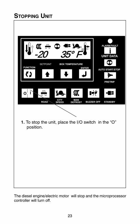
1. To stop the unit, place the I/O switch in the “O”position.
The diesel engine/electric motor will stop and the microprocessorcontroller will turn off.

24
PRODUCT LOADING
BEFORE LOADING:
D Pre-cool the body. This will remove much of the heat from theinside of the body, and give the product better protection whenit is loaded.
D Place the unit in a defrost cycle immediately before loading. Thiswill remove moisture accumulated on the evaporator coil.
DURING LOADING:
D Turn the unit off!
D Check product temperature during loading.
D Ensure that the air return and supply opening remainunobstructed.
D Leaveapproximately 4 to 5 inches between the loadand the frontwall for air return to the unit.
D Leave at least 10 to 12 inches between the top of the load andthe ceiling to ensure that there is nothing to prevent airflow tothe rear of the body
D Load product on pallets to provide free air return to unit andimprove product protection.
Proper air circulation in the truck body -- air that can move aroundand through the load -- is a critical element in maintaining productquality during transport. If air cannot circulate completely aroundthe load, hot spots or top-freeze can occur.
The use of pallets is highly recommended. Pallets, when loaded soair can flow freely through the pallets to return to the evaporator,help protect the product from heat that passes through the floor ofthe trailer. When using pallets, it is important to refrain fromstacking extra boxes on the floor at the rear of the trailer. This willcut off the airflow.

25
Product stacking is another important factor in protecting theproduct. Products that generate heat -- fruits and vegetables, forexample -- should be stacked so theair can flow through theproductto remove the heat. This is called “air stacking” the product.Products that do not create heat -- meats and frozen products --should be stacked tightly in the center of the trailer. All productsshould be kept away from the side-walls of thebody, to allowair flowbetween the body and the load; this prevents heat filtering throughthe walls from affecting the product.
It is important to check the temperature of the product being loadedto ensure that it is at the correct temperature for transport. Therefrigeration unit is designed to maintain the temperature of theproduct at the temperature at which it was loaded. It was notdesigned to cool warm product.

26
RECOMMENDED TRANSPORT TEMPERATURES
Below are some general recommendations on product transporttemperatures and operatingmodes for the unit. These are includedfor reference only and should not be considered preemptive of theset point required by the shipper or receiver.
More detailed information can be obtained from your CarrierTransicold dealer.
ProductSetpoint Range
Operating Mode*Product_F _C
Operating Mode*
Bananas 56 to 58 13 to 14 Continuous
Fresh fruits andvegetables
33 to 38 0.5 to 3 Continuous
Fresh meats andseafood
28 to 32 --2 to 0 Auto-Start/Stop orContinuous
Dairy Products 33 to 38 0.5 to 3 Auto-Start/Stop orContinuous
Ice 15 to 20 --10 to --7 Auto-Start/Stop**
Frozen fruits andvegetables
--10 to 0 --23 to --18 Auto-Start/Stop**
Frozen meats andseafood
--10 to 0 --23 to --18 Auto-Start/Stop**
Ice Cream --20 to --15 --29 to --26 Auto-Start/Stop**
* During delivery cycles that include frequent stops and dooropenings, it is recommended that the unit always beoperated in thecontinuous runmode to help ensure product quality. If it is possible,the unit should be turned off during the time the body doors areopen to help preserve the product temperature.**Variations may be necessary for very high or very low ambienttemperatures. 1.

27
PROBLEMS
Everything possible has been done to ensure that your unit is themost reliable, trouble-free equipment available today. If, however,you run into problems the following section may be of assistance.
If you do not find the trouble that you have experienced listed,please call your Carrier Transicold dealer for assistance.
General ProblemsUnit won’t crank. Check battery condition.
Check battery connections.Check all fuses
Unit won’t start. Check fuel level.Check all fuses
Unit won’t run. Check fuel level.Check engine oil level.Check all fuses
Unit stops running. Check belts.Check engine oil level.Check coolant level.Check fuel level.Check all fuses.
Unit not cooling properly. Defrost unit.Check evaporator for airflow restriction.Check condenser for airflow restriction.Check body for damage or air leaks.
Fault Display on Cab CommandService 1Service 2
Unit is calling attention to a normal ser-vice requirement (oil change, etc.). Nor-mally this does not require immediateattention.
28
TROUBLESHOOTING
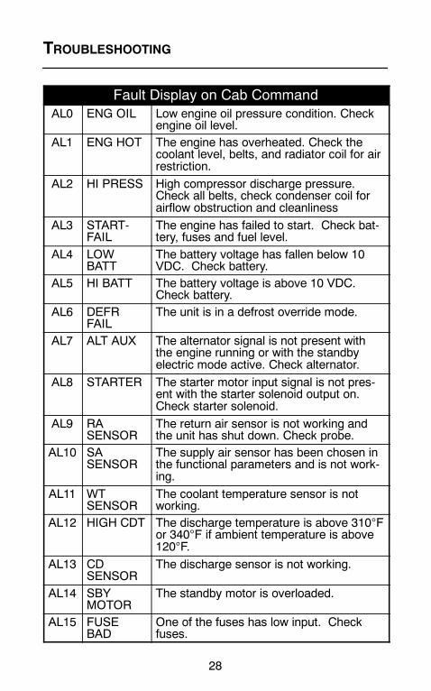
Fault Display on Cab CommandAL0 ENG OIL Low engine oil pressure condition. Check
engine oil level.AL1 ENG HOT The engine has overheated. Check the
coolant level, belts, and radiator coil for airrestriction.
AL2 HI PRESS High compressor discharge pressure.Check all belts, check condenser coil forairflow obstruction and cleanliness
AL3 START-FAIL
The engine has failed to start. Check bat-tery, fuses and fuel level.
AL4 LOWBATT
The battery voltage has fallen below 10VDC. Check battery.
AL5 HI BATT The battery voltage is above 10 VDC.Check battery.
AL6 DEFRFAIL
The unit is in a defrost override mode.
AL7 ALT AUX The alternator signal is not present withthe engine running or with the standbyelectric mode active. Check alternator.
AL8 STARTER The starter motor input signal is not pres-ent with the starter solenoid output on.Check starter solenoid.
AL9 RASENSOR
The return air sensor is not working andthe unit has shut down. Check probe.
AL10 SASENSOR
The supply air sensor has been chosen inthe functional parameters and is not work-ing.
AL11 WTSENSOR
The coolant temperature sensor is notworking.
AL12 HIGH CDT The discharge temperature is above 310°For 340°F if ambient temperature is above120°F.
AL13 CDSENSOR
The discharge sensor is not working.
AL14 SBYMOTOR
The standby motor is overloaded.
AL15 FUSEBAD
One of the fuses has low input. Checkfuses.
29
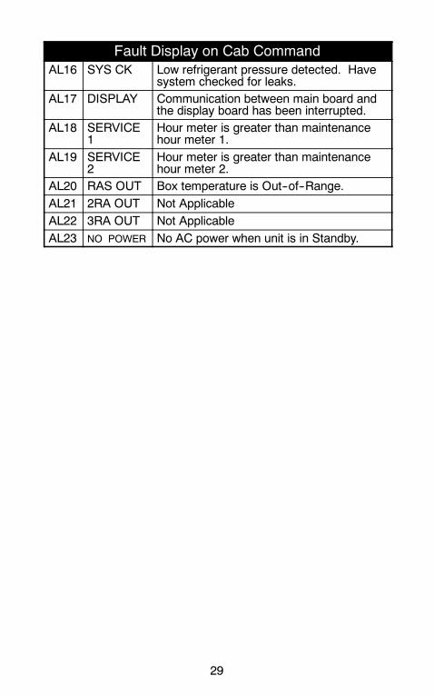
Fault Display on Cab CommandAL16 SYS CK Low refrigerant pressure detected. Have
system checked for leaks.AL17 DISPLAY Communication between main board and
the display board has been interrupted.AL18 SERVICE
1Hour meter is greater than maintenancehour meter 1.
AL19 SERVICE2
Hour meter is greater than maintenancehour meter 2.
AL20 RAS OUT Box temperature is Out--of--Range.AL21 2RA OUT Not ApplicableAL22 3RA OUT Not ApplicableAL23 NO POWER No AC power when unit is in Standby.

30
RELAY BOARD
The fuses and relays that protect the unit are located on the relayboard in the control box on the roadside of the unit. They may beaccessed by loosening the screws that hold the control panelclosed.
EFHR3
F2
F1
F3
F4
F5
F8
F7F10
F9F11
F6

31
Fuse Identification
Fuse Purpose Capacity(Amps)
F1 Main Fuse 80AF2 RCR Fuse 5AF3 Run Relay Fuse 15AF4 Heat Relay Fuse 3A
F5 Speed Relay Fuse 10AF6 Unloader Fuse (850 & 950) 5AF7 Defrost Damper Relay Fuse 15AF8 Evaporator Fan Motor 1 Fuse 20AF9 Evaporator Fan Motor 2 Fuse 20AF10 Evaporator Fan Motor 3 Fuse 20AF11 Fuel Pump Fuse 5A
F12 Fuel Heater Fuse (on fuel adding har-ness) 25A
Relay Identification
Desig. ItemSSR Starter Solenoid Relay
EFMR1 Electric Fan Motor RelayEFMR2 Electric Fan Motor RelayEFMR3 Electric Fan Motor RelayDDR Defrost Damper Solenoid Relay (Option)UFR Unloader Front Relay (850 & 950)CCR Compressor Clutch RelaySR Speed RelayHR1 Heat Relay 1DER Diesel Electric RelayRR Run Relay
GPR Glow Plug RelayRCR Run Control RelayEHR Evaporator Heater Relay

32
UNIT MAINTENANCE
Engine oil -- the oils recommended for use in your refrigeration unitmust comply with the American Petroleum Institute’s (API) SG/CDrating. The use of any oil that does not meet this rating may affectthe warranty on the engine in the unit. The use of oil of the properweight (viscosity) is also essential. The following chart indicates theSAE Weight Rating of the oil to be used in various climates:
_F
_C
10W or 10W30
20W or 15W40
30W or15W40
The following oils are approved for use in the Supra range of units:
In the US, CanadaMexico, Central and South America, any oil thatmeets the above API specification is suitable for use in the Suprarange of units. Mobil Delvac1 is the only approved synthetic oil.

33
UNIT MAINTENANCE SCHEDULE
For the most reliable operation and for maximum life, your unitrequires regular maintenance. This includes oil and filter changes,fuel and air filter replacement, coolant replacement. Maintenanceshould be performed on the following schedule:
SERVICE SCHEDULE FOR SUPRA 550
Petroleum andSynthetic Oil-With and With-out Bypass At250 Hours
D Check engine cooling system.D Check and clean the air filter.D Check all bolts, screws and unit mounting bolts
for tightness. Tighten as required.D Check all belts.
Petroleum OilWithout BypassAt 500 and every500 hours afterPetroleum Oil-With BypassAt 600 and every600 hours afterSynthetic Oil-Without BypassAt 1000 and ev-ery 1000 hoursafterSynthetic OilWith BypassAt 1200 and ev-ery 1200 hoursafter
D Replace lube oil and filter.D Check engine cooling system.D Check and clean the air filter.D Check all belts.

34
SERVICE SCHEDULE FOR SUPRA 550 (CONT)
Petroleum andSynthetic OilWith and With-out Bypass At1500 Hours
D Check fuel pump filter.D Replace the cartridge of the dry air filter.D Check battery terminals and fluid level.D Check compressor oil level. Use polyol ester
oil (POE) approved by CARRIER.D Check alternator brushes. Check for diesel and
standby hours.D Check engine thermostat.D Check defrost:
-- Check timer setting and function-- Check refrigerant control valves-- Fans stop or defrost damper closes-- Defrost ends automatically-- Water drains from evaporator
D Check fan motor brushes.D Check and adjust rocker arms.D Check belts as necessary.
Petroleum andSynthetic OilWith and With-out Bypass At2000 Hours
D Replace oil filter.D Clean radiator/condenser coil.D Check refrigerant level.
Petroleum andSynthetic OilWith and With-out Bypass At3000 Hours
D Change fan motor brushes.D Check and rebuild alternator.D Check engine speed:
High -- 2300 to 2350Low -- 1800 to 1850
Petroleum andSynthetic OilWith and With-out Bypass WithStandard Cool-ant At 6000Hours
D Check all belt tension pulleysD Change anti--freeze and flush cooling system.D Check bearings in clutch and electric motors.D Clean and adjust fuel injectors.
Petroleum andSynthetic OilWith and With-out Bypass WithExt. Life At12000 Hours
D Check all belt tension pulleysD Change anti--freeze and flush cooling system.D Check bearings in clutch and electric motors.D Clean and adjust fuel injectors.

35
SERVICE SCHEDULE FOR SUPRA 650/750/850
Petroleum andSynthetic Oil-With and With-out Bypass At250 Hours
D Check engine cooling system.D Check and clean the air filter.D Check all bolts, screws and unit mounting bolts
for tightness. Tighten as required.D Check all belts.
Petroleum OilWithout BypassAt 750 and every750 hours afterPetroleum Oil-With BypassAt 1000, 1500,3000 HoursSynthetic Oil-Without BypassAt 1500 and ev-ery 1500 hoursafterSynthetic OilWith BypassAt 2000 and ev-ery 2000 hoursafter
D Replace lube oil and filter.D Check engine cooling system.D Check and clean the air filter.D Check all belts.
Petroleum andSynthetic OilWith and With-out Bypass At1500 Hours
D Check fuel pump filter.D Replace the cartridge of the dry air filter.D Check battery terminals and fluid level.D Check compressor oil level. Use polyol ester
oil (POE) approved by CARRIER.D Check alternator brushes. Check for diesel and
standby hours.D Check engine thermostat.D Check defrost:
-- Check timer setting and function-- Check refrigerant control valves-- Fans stop or defrost damper closes-- Defrost ends automatically-- Water drains from evaporator
D Check fan motor brushes.D Check and adjust rocker arms.D Check belts as necessary.

36
SERVICE SCHEDULE FOR SUPRA 650/750/850 (CONT)
Petroleum andSynthetic OilWith and With-out Bypass At2000 Hours
D Replace oil filter.D Clean radiator/condenser coil.D Check refrigerant level.
Petroleum andSynthetic OilWith and With-out Bypass At3000 Hours
D Change fan motor brushes.D Check and rebuild alternator.D Check engine speed:
High -- 2300 to 2350Low -- 1800 to 1850
Petroleum andSynthetic OilWith and With-out Bypass WithStandard Cool-ant At 6000Hours
D Check all belt tension pulleysD Change anti--freeze and flush cooling system.D Check bearings in clutch and electric motors.D Clean and adjust fuel injectors.
Petroleum andSynthetic OilWith and With-out Bypass WithExt. Life At12000 Hours
D Check all belt tension pulleysD Change anti--freeze and flush cooling system.D Check bearings in clutch and electric motors.D Clean and adjust fuel injectors.
37
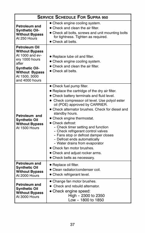
SERVICE SCHEDULE FOR SUPRA 950
Petroleum andSynthetic Oil-Without BypassAt 250 Hours
D Check engine cooling system.D Check and clean the air filter.D Check all bolts, screws and unit mounting bolts
for tightness. Tighten as required.D Check all belts.
Petroleum OilWithout BypassAt 1000 and ev-ery 1000 hoursafterSynthetic Oil-Without BypassAt 1500, 3000and 4000 hours
D Replace lube oil and filter.D Check engine cooling system.D Check and clean the air filter.D Check all belts.
Petroleum andSynthetic OilWithout BypassAt 1500 Hours
D Check fuel pump filter.D Replace the cartridge of the dry air filter.D Check battery terminals and fluid level.D Check compressor oil level. Use polyol ester
oil (POE) approved by CARRIER.D Check alternator brushes. Check for diesel and
standby hours.D Check engine thermostat.D Check defrost:
-- Check timer setting and function-- Check refrigerant control valves-- Fans stop or defrost damper closes-- Defrost ends automatically-- Water drains from evaporator
D Check fan motor brushes.D Check and adjust rocker arms.D Check belts as necessary.
Petroleum andSynthetic OilWithout BypassAt 2000 Hours
D Replace oil filter.D Clean radiator/condenser coil.D Check refrigerant level.
Petroleum andSynthetic OilWithout BypassAt 3000 Hours
D Change fan motor brushes.D Check and rebuild alternator.D Check engine speed:
High -- 2300 to 2350Low -- 1800 to 1850

38
SERVICE SCHEDULE FOR SUPRA 950 (CONT)
Petroleum andSynthetic OilWithout BypassWith StandardCoolant At 6000Hours
D Check all belt tension pulleysD Change anti--freeze and flush cooling system.D Check bearings in clutch and electric motors.D Clean and adjust fuel injectors.
Petroleum andSynthetic OilWithout BypassWith Ext. Life At12000 Hours
D Check all belt tension pulleysD Change anti--freeze and flush cooling system.D Check bearings in clutch and electric motors.D Clean and adjust fuel injectors.
Oil Type Supra 550 Supra650/750/850 Supra 950
Petroleum 500 Hours* 750 Hours* 100 Hours*W/Bypass 600 Hours* 1000 Hours* N/A
Synthetic** 1000Hours**
1500Hours**
2000Hours**
W/Bypass 1200 Hours* 2000 Hours* N/A
* Maximum oil drain interval is one year (12 months).** Mobil Delvac1 is the only approved synthetic oil. Maximumoil drain interval is two (2) years. Oil filter change required oncea year (every 12 months).
These maintenance schedules are based on the use of approvedoils and regular Pre-Trip inspections of theunit. Failure to follow therecommended maintenance schedule may affect the life andreliability of the refrigeration unit.
In addition to the above service requirements please adhere to thefollowing:
D All units are shippedwith Extended Life Coolant. Replaceevery5 years/12,000 hours.
A more detailed description of service requirements andprocedures can be found in the Service andOperations Manual foryour unit. Thismanualmay beobtained fromany Carrier Transicolddealer.
39
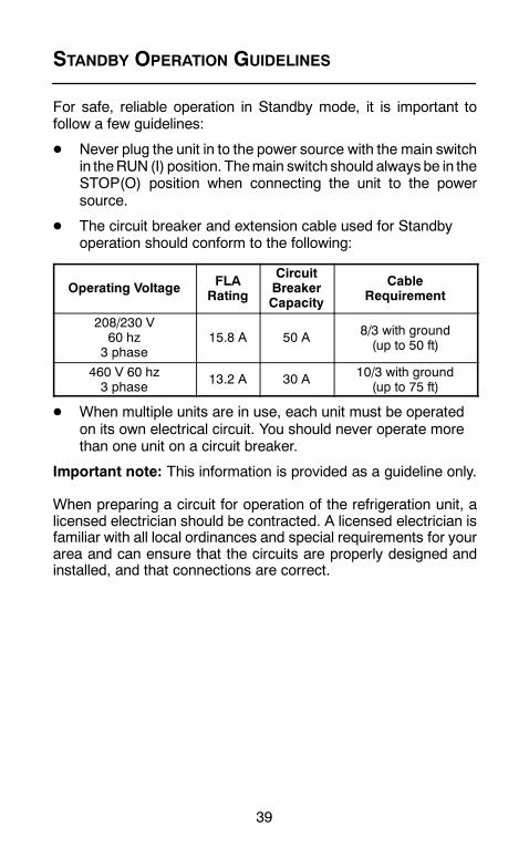
STANDBY OPERATION GUIDELINES
For safe, reliable operation in Standby mode, it is important tofollow a few guidelines:
D Never plug the unit in to the power source with the main switchin theRUN (I) position. Themain switch should always be in theSTOP(O) position when connecting the unit to the powersource.
D The circuit breaker and extension cable used for Standbyoperation should conform to the following:
Operating Voltage FLARating
CircuitBreakerCapacity
CableRequirement
208/230 V60 hz3 phase
15.8 A 50 A 8/3 with ground(up to 50 ft)
460 V 60 hz3 phase
13.2 A 30 A 10/3 with ground(up to 75 ft)
D When multiple units are in use, each unit must be operatedon its own electrical circuit. You should never operate morethan one unit on a circuit breaker.
Important note: This information is provided as a guideline only.
When preparing a circuit for operation of the refrigeration unit, alicensed electrician should be contracted. A licensed electrician isfamiliar with all local ordinances and special requirements for yourarea and can ensure that the circuits are properly designed andinstalled, and that connections are correct.

40
EMERGENCY ROAD SERVICE
At Carrier Transicold we’re working hard to give you completeservice when and where you need it. That means a worldwidenetwork of dealers that offer 24-hour emergency service. Theseservice centers are manned by factory trained service personneland backed by extensive parts inventories that will assure you ofprompt repair.
Should you experience a unit problem with your refrigeration unitduring transit, follow your company’s emergency procedure orcontact the nearest Carrier Transicold service center. Consult theShortstop Service Centers directory to locate the service centernearest you. This directory may be obtained from your CarrierTransicold dealer.
If you are unable to reach a service center, call our 24-hour ActionLine:
Call (800) 448-1661 from any phone in the United States orCanada.When calling, please have the following information readyfor fastest service:S Your name, the name of your company, and your location.S A telephone number where you can be called back.S Refrigeration unit model number and serial number.S Box temperature, set point and product.S Brief description of the problem you are having, and what youhave already done to correct the problem.
We will do everything we can to get your problem taken care of andget you back on the road.
©2006 Carrier Corporation D Printed in U. S. A. 0306
Carrier Transicold Division,Carrier CorporationTruck/Trailer Products GroupP.O. Box 4805Syracuse, N.Y. 13221 U.S A
www.carrier.transicold.com
North AmericaCarrier Transicold700 Olympic DriveAthens, GA 30601 USATel: 1--706--357--7223Fax: 1--706--355--5435
Central Americaand MexicoEjercito Nacional No. 418Piso 9, Torre YumalCol. Chapultepec Morales11570 Mexico, D.F.Tel: (5255) 9126.0300Fax: (5255) 9126.0373
A member of the United Technologies Corporation family. Stock symbol UTX
CALIFORNIAProposition 65 Warning
Diesel engine exhaust and some ofits constituents are known to theState of California to cause cancer,birth defects,and other reproductiveharm.