operation, safety, and maintenance manual
TRANSCRIPT

OPERATION, SAFETY, AND MAINTENANCE
MANUAL
Hy-Brid Scissors Lift Models
HB 1030 HB 1430
Self-Propelled Aerial Work Platform

1
Foreword The purpose of this Operations and Safety Manual is to provide users with the instructions and operating procedures essential to properly and safely operate the Custom Equipment Hy-Brid Lift for its intended purpose, to position personnel and their necessary tools and materials.
DANGER
THE OPERATION AND SAFETY MANUAL MUST BE READ AND UNDERSTOOD PRIOR
TO OPERATING THE MACHINE. THE USER/OPERATOR SHOULD NOT ACCEPT OPERATING RESPONSIBILITY UNTIL THE MANUAL HAS BEEN READ AND UNDERSTOOD AS WELL AS HAVING OPERATED THE LIFT UNDER SUPERVISION OF AN EXPERIENCED AND QUALIFIED OPERATOR. BECAUSE THE MANUFACTURER HAS NO DIRECT CONTROL OVER MACHINE APPLICATION AND OPERATION, PROPER SAFETY PRACTICES ARE THE RESPONSIBILITY OF THE USER AND ALL OPERATING PERSONNEL.
WARNING
ANY MODIFICATION ON THIS MACHINE WITHOUT THE EXPRESS WRITTEN CONSENT
OF THE MANUFACTURER IS PROHIBITED. If there is a question on application and/or operation, contact: Custom Equipment, Inc. 2647 Hwy 175 Richfield, WI 53076 USA Phone: 262-644-1300 Fax: 262-644-1320 SUPO-602 Revisions Rev 09: 4/24/09: Decal Location (DE603) Rev 10:6/22/09: Curved Railing, Slide Lock Rev (cover, p. 7, 12)
2
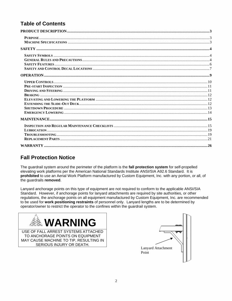
Lanyard Attachment Point
Table of Contents PRODUCT DESCRIPTION ..................................................................................................................................................... 3
PURPOSE .................................................................................................................................................................................. 3 MACHINE SPECIFICATIONS .................................................................................................................................................... 3
SAFETY ..................................................................................................................................................................................... 4
SAFETY SYMBOLS ................................................................................................................................................................... 4 GENERAL RULES AND PRECAUTIONS ..................................................................................................................................... 4 SAFETY FEATURES .................................................................................................................................................................. 6 SAFETY AND CONTROL DECAL LOCATIONS .......................................................................................................................... 7
OPERATION ............................................................................................................................................................................. 9
UPPER CONTROLS ................................................................................................................................................................. 10 PRE-START INSPECTION ....................................................................................................................................................... 11 DRIVING AND STEERING ....................................................................................................................................................... 11 BRAKING ............................................................................................................................................................................... 12 ELEVATING AND LOWERING THE PLATFORM ..................................................................................................................... 12 EXTENDING THE SLIDE-OUT DECK ...................................................................................................................................... 12 SHUTDOWN PROCEDURE ...................................................................................................................................................... 13 EMERGENCY LOWERING ...................................................................................................................................................... 14
MAINTENANCE ..................................................................................................................................................................... 15
INSPECTION AND REGULAR MAINTENANCE CHECKLISTS .................................................................................................. 15 LUBRICATION ........................................................................................................................................................................ 19 TROUBLESHOOTING .............................................................................................................................................................. 19 REPLACEMENT PARTS .......................................................................................................................................................... 21
WARRANTY ........................................................................................................................................................................... 26
Fall Protection Notice The guardrail system around the perimeter of the platform is the fall protection system for self-propelled elevating work platforms per the American National Standards Institute ANSI/SIA A92.6 Standard. It is prohibited to use an Aerial Work Platform manufactured by Custom Equipment, Inc. with any portion, or all, of the guardrails removed. Lanyard anchorage points on this type of equipment are not required to conform to the applicable ANSI/SIA Standard. However, if anchorage points for lanyard attachments are required by site authorities, or other regulations, the anchorage points on all equipment manufactured by Custom Equipment, Inc. are recommended to be used for work positioning restraints of personnel only. Lanyard lengths are to be determined by operator/owner to restrict the operator to the confines within the guardrail system.
WARNING
USE OF FALL ARREST SYSTEMS ATTACHED TO ANCHORAGE POINTS ON EQUIPMENT
MAY CAUSE MACHINE TO TIP, RESULTING IN SERIOUS INJURY OR DEATH.

3
Product Description Purpose Custom Equipment's Hy-Brid Scissors Lift is an aerial work platform designed for compact size, ease of operation, and operator safety. The purpose of the machine is to position personnel and their necessary tools and materials. Machine Specifications (Subject to Change)
HB1030 HB1430 DIMENSIONS
Working Height (maximum) 16 ft. 4.87 m 20 ft. 6.1 m Platform Height (maximum) 10 ft. 3 m 14 ft. 4.26 m Stowed Height 66.88 in. 1.7 m 71 in. 2.16 m Ground Clearance (Pothole Guard Stowed) 2 in. 5.08 cm 2.75 in. 7 cm Ground Clearance (Pothole Guard Engaged) 0.75 in. 1.9 cm 0.75 in. 1.9 cm Overall Width 30 in 0.76 m 30 in 0.76 m Overall Length 63.5 in. 1.61 m 63.5 in. 1.61 m Platform (Retracted, Inside) 25 in. x 60 in. 0.64 mx1.52 m 25 in. x 60 in. 0.64 mx1.52 m Slide-Out Deck Length 30 in. 0.76m 30 in. 0.76m Guard Rail Height 42 in. 1 m 42 in. 1 m Toe Board Height 4 in. .1 m 4 in. .1 m Platform Entrance 21 in. 0.53 m 25 in. 0.3 m Step Height NA NA 12 in. 0.3 m Wheel Base 51 in. 1.3 m 51 in. 1.3 m Wheel Track 23.63 in. 0.6 m 23.63 in. 0.6 m Turning Radius (Inside) 21 in. 0.53 m 21 in. 0.53 m Tire Size (Solid, Non-Marking)-Front 8 in. 20.3 cm 10 in. 25.4 cm Tire Size (Solid, Non-Marking)-Rear 10 in. 25.4 cm 10 in. 25.4 cm RATED LOAD
Lift Capacity (Evenly Distributed): 750 lbs. 340.2 kg 670 lb. 304 kg. Slide-Out Deck Capacity 250 lbs 113.4 kg 250 lb. 113.4 kg. Horizontal/Manual Force 112.5 lb. 500 N 100.5 lb. 447 N FLOOR LOADING
Machine Weight (Unloaded) (Approx.) 1275 lb. 578.kg 1650 lb. 748.4 kg Minimum Wheel Load 62.2 psi 428.58 kPa 80.5 psi 555 kPa Maximum Wheel Load 98.8 psi 680.2 kPa 113.2 psi 780.5 kPa Minimum Machine Loading 96.37 psf 4.61 kPa 124.5 psf 5.96 kPa Maximum Machine Loading 153.06 psf 7.33 kPa 175 psf 8.38 kPa ENVIRONMENTAL LIMITATIONS
Wind No Windy Conditions/Indoor Use Only ( C ) No Windy Conditions/Indoor Use Only ( C )
Rated Slope Level Surface Level Surface Tilt Sensor Activated 2° 2° 2° 2°
Gradeability 30% 30% 30% 30% Temperature -4° F-104° F -20° C-40° C -4° F-104° F -20° C-40° C Vibration 8.2 ft/s2 max 2.5 m/s2 max 8.2 ft/s2 max 2.5 m/s2 max POWER SYSTEMS
Drive System (Proportional Electric): Drive Speed (Platform Elevated) 0-0.7 mph 0-.31 m/s 0-0.7 mph 0-.31 m/s Drive Speed (Platform Lowered) 0-2mph 0-.89 m/s 0-2mph 0-.89 m/s Lift/Lower Speed 15/22 sec 15/22 sec 21/31 sec 21/31 sec Hydraulic Pressure (max) 1300 psi 8963 kPa 2000 psi 13 790 kPa Hydraulic Fluid Capacity 1.325 gal 5.38 L 1.325 gal 5.38 L Power System-Voltage 24V DC 24V DC 24V DC 24V DC Batteries-Deep Cycle Marine (2) 12V (2) 12V (2) 12V (2) 12V

4
Safety Safety Symbols Warnings and instructions that have a direct impact on safety are identified with the following signals:
"DANGER" indicates an imminently hazardous situation, which, if not avoided, will result in death or serious injury.
"WARNING" indicates a potentially hazardous situation, which, if not avoided, could result in death or serious injury.
"CAUTION" indicates a potentially hazardous situation which, if not avoided, could result in minor or moderate injury or damage to equipment.
General Rules and Precautions Custom Equipment, Inc. designed the Hy-Brid Lift self-propelled scissor lift to be safe and reliable. It is intended for elevating personnel, along with their necessary tools and materials to overhead work locations. An operator of any type of work platform is subject to certain hazards that cannot be protected by mechanical means. It is therefore essential that operators be competent, careful, physically and mentally fit and thoroughly trained in safe operation of this machine. Although Custom Equipment, Inc. conforms to specified ANSI & OSHA requirements, it is the responsibility of the owner to instruct operators with the safety requirements made not only by Custom Equipment, Inc., but by the various safety boards in your area, as well as additional requirements set forth by ANSI & OSHA. If you come across a situation that you think might be unsafe, stop the platform and request further information from qualified sources before proceeding.
WARNING
NEVER REACH BETWEEN SCISSORS LINKS OR PROP UP PLATFORM.
DANGER
FAILURE TO FOLLOW THIS WARNING WILL CAUSE DEATH OR PERSONAL INJURY.
WARNING
FAILURE TO FOLLOW THIS WARNING MAY CAUSE DEATH OR PERSONAL INJURY.
CAUTION
FAILURE TO FOLLOW THIS WARNING MAY CAUSE INJURY OR DAMAGE EQUIPMENT.

5
Only qualified operators may operate this unit. All operators must read and understand the Operation and Safety Manual. They must understand all
decals and warning labels on unit. ANSI A92.6 and other applicable standards identify requirements of all parties who may be involved with
self-propelling elevating work platforms. Owner/user/operator must be familiar with Sections 6, 7, 8, 9, and 10, which contain responsibilities of the owner, users, operators, lessors, and lessees including safety, training, inspection, maintenance and operation. A copy of the ANSI Standard is considered part of this machine.
Do not work on platform if your physical condition is such that you feel dizzy or unsteady in any way. Do not neglect/misuse machine. Report any misuse of equipment to proper personnel. Prevent unauthorized use; when unit is not in use, remove key. It is recommended all personnel on unit wear headgear (hard hats).
Use machine only for purposes for which it was intended.
Lift should never be used as a crane. Never use unit as electrical grounds for arc welding. Do not override any hydraulic, mechanical, or electrical safety devices.
Check job site for unsafe working conditions.
Unit must be on hard level surface before elevating. Do not operate on incline or uneven surface. Do not use outdoors in windy conditions or electrical storms.
DANGER
DO NOT OPERATE MACHINE NEAR POWER LINES. THE PLATFORM AND ENCLOSURES
ARE NOT INSULATED.
You must maintain a clearance of at least 10 feet between any part of the machine, or its load, and any electrical line or apparatus carrying over 300 volts up to 50000 volts. One-foot additional clearance is required for each additional 30,000 volts.
Watch out for others. Keep others clear of operating platform. Never allow others to pass under a raised platform or position the platform over someone.
Equipment is only as safe as the operator.
Do not enter or exit platform while machine is in motion. Never mount or dismount a raised platform. Make sure entry gate is secured before operating machine from the platform. Never belt or tie off to an adjacent structure. Do not exceed the load capabilities of the platform. Distribute load evenly over platform floor area. Secure tools and materials. Do not use ladders or scaffolding on the platform to obtain greater height. Personnel must maintain a firm footing on the platform floor and work only within the platform area. It is recommended to avoid sudden braking or steering. Go slowly and leave more maneuvering room
during cold weather operation. Before operation, ensure that the machine is properly serviced.
Do not use machine if it is not working properly. Make sure platform rails and pins are secured. Operator shall use the maintenance lock when performing all types of maintenance procedures. Do not smoke while charging the battery.

6
Safety Features
Emergency Stop. This lift is equipped with two emergency stop switches, one at the platform control and one at the base control, that when activated, will render the unit inoperable until reset. To reset, pull the button out.
Automatic Parking Brake. Free Descent Protection. A velocity fuse is installed in the hydraulic circuit to prevent the platform from descending
in case of a ruptured hydraulic hose. The platform will be hydraulically locked whenever this velocity fuse activates. Emergency Manual Override. This machine is equipped with a manual override valve. When opened, the platform
will descend. Tilt Alarm. An audible alarm sounds when the machine is tilted. Drive and elevate functions are disabled when the
tilt sensor is disconnected. For some models, drive and elevate functions are disabled when tilted. Puncture-proof Wheels. Guardrails and Kick Plates (42”/4”). Non-slip Deck. Key Switch Security. Decals. Danger, Caution, and Warning decals are displayed at various locations on this unit. These decals are to
conform to ANSI-SIA A92.3-1990 standards as interpreted by Custom Equipment, Inc. Entrance Gate. Pothole Protection. Maintenance Lock. The maintenance lock must be placed into position whenever the machine is being serviced in
the raised or partially raised position. Serious injury and/or death could result if maintenance lock is not used properly.
Figure 4: Pothole Protection
Figure 2: Maintenance Lock Storage
Insert Pins into Holes in Roller Track
Figure 1: Maintenance Lock Use
Figure 3: Entry Gate

7
Safety and Control Decal Locations

8
PART # DESCRIPTION QTY. DE600-01 WARNING-INSPECT 1
DE600-02 or DE600E-02 DANGER-IMPROPER USE DECAL 1 DE600-03 or DE600-3A MAX CAPACITY DECAL 3
DE600-04 PLAT EXT & GATE DECAL 1 DE600-05 DANGER TIP DECAL 1 DE600-06 REPLACE OEM ONLY DECAL 2 DE600-07 DO NOT POWERWASH DECAL 1 DE600-08 WARNING BATTERY GAS DECAL 1 DE600-09 ELECTROCUTION HAZARD DECAL 2 DE600-10 WARNING-IMPROPER USE DECAL 1 DE600-11 E-DOWN TURN BRASS DECAL 1 DE600-12 FORK POCKET DECAL 1 DE600-14 MAINT LOCK PIN DECAL 3 DE600-15 E-DOWN LOCATION DECAL 1
DE600-16A KEEP CLEAR DECAL (KEEP) 2 or 4 DE600-16B KEEP CLEAR DECAL (CLEAR) 2 or 4 DE600-17 SAFETY STRIPE 2 or 4 DE600-18 BATTERY WEIGHT DECAL 2 DE600-19 LOWER CONTROL DECAL 1 DE600-21 BRAKE RELEASE DECAL 1
DE-601 NAME LOGO DECAL 1
DE602 OR DE602-1 SERIAL NUMBER PLATE (OR DE602C OR DE602-1C)
1
DE603 OR DE603-1 MODEL NUMBER DECAL (FOR SOME MODELS, ALSO DE603C, DE603J)
2
DE-604 JOYSTICK DECAL (2 PIECES) 1
DE605 OR DE605-1 SMALL SERIAL NO. REFERENCE (OR DE605C OR DE605-1C)
1
DE608 WWW.HYBRIDLIFTS.COM 2 DE609 HY-BRID LIFTS 2 DE610 LOWER CUSTOM EQUIPMENT LOGO 2 DE611 NO FORK DECAL 1 DE612 PH WARNING DECAL 2 DE613 LANYARD ATTACHMENT POINT DECAL 1
DE616 NO FORK DECAL (NOT ON ALL MODELS)
2
DE617 CHARGER CORD LOCATION DECAL 1

9
Operation Preliminary Unpacking Instructions and Dealer Inspection Maintenance locks must be engaged prior to inspecting or servicing the unit when the platform is extended. Inspect machine for any possible damage during shipment; perform a pre-delivery inspection. Reset emergency stop switches, if necessary. Loading and Unloading Procedures
WARNING
DO NOT OVER-TIGHTEN LOAD BINDERS WHEN SECURING LOAD FOR TRANSPORT
TIE DOWN WARNING – Do not over-tighten load binders when securing load for transport. Damage will occur due to the design intent of this product. A forklift pocket and tie down/lift points are provided for loading and unloading and for securing the machine on a trailer or truck bed. Do not use forklift from back of machine.
Forklift
Figure 7: Forklift Pocket, Front Tie Down/Lift Points
Tie Down/ Lift Points
Tie Down/ Lift Points
Figure 6: Back Tie Down/Lift Points

10
Lower Controls
Figure 8: Lower Controls
Upper Controls
Item Control Description 1 Key Enables machine controls
2 Hour Meter/ Battery Gauge
Indicates total elapsed time machine has been operated. Indicates charge left in battery.
3 Emergency Stop
Push to stop all functions in emergency. To reset, pull knob out.
4 Tilt Alarm
Sounds audible alarm when machine tilted more than 2. When alarm sounds, platform should not be elevated or, if elevated, should be lowered immediately.
5 Descent Alarm
Sounds audible alarm when scissors is lowering.
6 Lift/Lower Switch
Controls lifting and lowering of platform from the base.
7 LED Used for drive motor control troubleshooting diagnostics
Item Control Description 1 Lift/Lower Enable Button Must be pressed to lift and lower platform from platform. 2 Emergency Stop Push to stop all functions in emergency. To reset, pull knob out. 3 Drive Enable Switch Must be depressed to drive. 4 Thumb Steering Switch Press switch with thumb to the left to turn wheels left, right to turn wheels right.5 Joystick Controls speed and steering. 6 Lift/Lower Switch Controls lifting and lowering of platform from the base.
Figure 9: Upper Controls Figure 10: Upper Controls Top View

11
Pre-start Inspection Before use each day or at the beginning of each shift, the machine shall be given a visual inspection and functional test. Repairs (if any) must be made prior to operating the machine, as it is critical to ensure safe operation of the machine. A checklist for pre-start inspection can be found in the Maintenance section of this manual.
DANGER
THE OPERATOR MUST BE AWARE OF THE ENVIRONMENT. DO NOT RAISE THE PLATFORM IF THE MACHINE IS NOT ON A FIRM, LEVEL SURFACE.
To operate, ensure that the key in the lower control panel is in the "ON" position. Driving and Steering
WARNING
CHECK THAT THE ROUTE OF TRAVEL TO BE TAKEN IS CLEAR OF PEOPLE, OBSTRUCTIONS, DEBRIS, HOLES, AND DROP OFFS, AND IS CAPABLE OF SUPPORTING THE MACHINE.
Always check front steer wheel direction before driving. To activate drive function, depress the Drive Enable Bar on the Joystick. Moving the joystick handle away from the operator will cause FORWARD travel and pulling the joystick toward the operator will cause REVERSE travel. Travel speed is proportional and is controlled by the joystick. The farther it is moved, the faster the speed will be. The joystick returns to the neutral position when released. Use the Thumb Steering Switch on the end of the Joystick to steer left and right. Pressing the switch to the causes wheels to turn left, to the right, wheels turn right. The steer switch returns to neutral position when released. Steer wheels do not center themselves after a turn; they must be returned to the straight-ahead position with the steer switch.
WARNING
STEERING BRACKETS EXTENDING BEYOND THE SIDES OF THE BASE MAY OCCUR IN
TIGHT TURNING SITUATIONS TIGHT TURNING WARNING – Potential damage to walls, etc., may occur in tight turning situations due to the steering brackets extending beyond the sides of the base.
12
Braking
WARNING
PUSHING THE EMERGENCY STOP BUTTON WILL APPLY BRAKES IMMEDIATELY. THIS MAY CAUSE UNEXPECTED PLATFORM MOVEMENT AS THE MACHINE COMES TO A SUDDEN STOP. BRACE
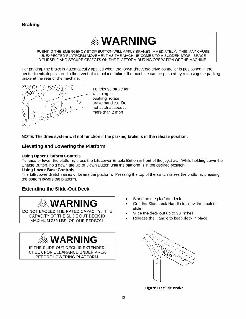
YOURSELF AND SECURE OBJECTS ON THE PLATFORM DURING OPERATION OF THE MACHINE. For parking, the brake is automatically applied when the forward/reverse drive controller is positioned in the center (neutral) position. In the event of a machine failure, the machine can be pushed by releasing the parking brake at the rear of the machine.
NOTE: The drive system will not function if the parking brake is in the release position. Elevating and Lowering the Platform Using Upper Platform Controls To raise or lower the platform, press the Lift/Lower Enable Button in front of the joystick. While holding down the Enable Button, hold down the Up or Down Button until the platform is in the desired position. Using Lower Base Controls The Lift/Lower Switch raises or lowers the platform. Pressing the top of the switch raises the platform, pressing the bottom lowers the platform. Extending the Slide-Out Deck
Stand on the platform deck. Grip the Slide Lock Handle to allow the deck to
slide. Slide the deck out up to 30 inches. Release the Handle to keep deck in place.
WARNING
DO NOT EXCEED THE RATED CAPACITY. THE CAPACITY OF THE SLIDE OUT DECK ID MAXIMUM 250 LBS. OR ONE PERSON.
WARNING
IF THE SLIDE-OUT DECK IS EXTENDED, CHECK FOR CLEARANCE UNDER AREA
BEFORE LOWERING PLATFORM.
To release brake for winching or pushing, rotate brake handles. Do not push at speeds more than 2 mph
Figure 11: Slide Brake
13
Charging the Battery This unit is equipped with deep cycle 12-volt batteries. The care and maintenance of your battery has much to do with how well this unit functions. Battery wiring and water level should be checked monthly. Do not overfill. The battery fluid will expand as it becomes warm from charging. When the cells are too full, fluid will seep out when charging. Note: The surrounding temperature greatly affects the power reserve within a battery. Example: A battery that is 100% charged at 80 degrees Fahrenheit drops to 65% at 32 degrees Fahrenheit. At 0 degrees, this battery will drop to 40%.
WARNING
LEAD-ACID BATTERIES GENERATE EXPLOSIVE GASES. KEEP SPARKS AND FLAME AWAY FROM BATTERIES. DO NOT
SMOKE WHILE CHARGING.
Park the machine on a level surface. Plug charger into a 120V AC outlet until charged.
Unplug charger.
WARNING
DO NOT OPERATE UNIT WHILE CHARGING.
CAUTION
NEVER ADD ACID TO BATTERY!
The solution is at its proper strength when the battery is manufactured. Use distilled water and keep fluid up to proper level. When required, water should be added to battery after charging, unless water level is below the plates. Shutdown Procedure
When finished with the machine, place the platform in the stowed position. Park the machine on a level surface. Carefully exit the platform using a constant three point dismount/grip. Remove key from lower control panel to prevent unauthorized use.

14
Emergency Lowering
Remove side cover and locate hydraulic pump. Push and turn knob located on down valve. Knob will pop up. To reset, push and turn the opposite direction.
WARNING
IF PLATFORM SHOULD FAIL TO LOWER, DO NOT ATTEMPT TO
CLIMB DOWN THE BEAM ASSEMBLY. SERIOUS INJURY MAY RESULT. HAVE AN EXPERIENCED OPERATOR USE THE EMERGENCY
LOWERING PROCEDURE TO SAFELY LOWER THE PLATFORM.
WARNING
BEFORE LOWERING PLATFORM, RETRACT THE DECK EXTENSION.
EMERGENCY DOWN KNOB
Figure 12: Hydraulic Pump

15
Maintenance
WARNING
FAILURE TO COMPLY WITH THE LISTED SAFETY PRECAUTIONS MAY RESULT IN MACHINE
DAMAGE, PERSONNEL INJURY OR DEATH.
Never work under an elevated platform until maintenance locks have been engaged. Remove all rings, watches, and jewelry when performing any maintenance. Do not wear long hair unrestrained or loose fitting clothing and neckties which may become caught on or
entangled in equipment. Observe and obey all warnings and cautions on machine and in manual. Keep oil, grease, water, etc. wiped from standing surfaces and handholds. Before making any adjustments, lubricating or performing any other maintenance, shut off all power
controls. Battery should always be disconnected during replacement of electrical components. Keep all support equipment and attachments stowed in their proper place. Use only approved, nonflammable cleaning solvents.
Inspection and Regular Maintenance Checklists
CAUTION
FAILURE TO PERFORM INSPECTIONS AND PREVENTITIVE MAINTENANCE AT RECOMMENDED INTERVALS MAY RESULT IN THE UNIT BEING OPERATED WITH A
DEFECT THAT MAY RESULT IN INJURY OR DEATH OF THE OPERATOR. Regular inspection and conscientious maintenance is important to efficient economical operation of this machine. It will help to assure that equipment will perform satisfactorily with a minimum or service and repair. The following inspection checklists are included in this manual: Pre-Delivery/Frequent, Pre-Start, and Monthly.
16
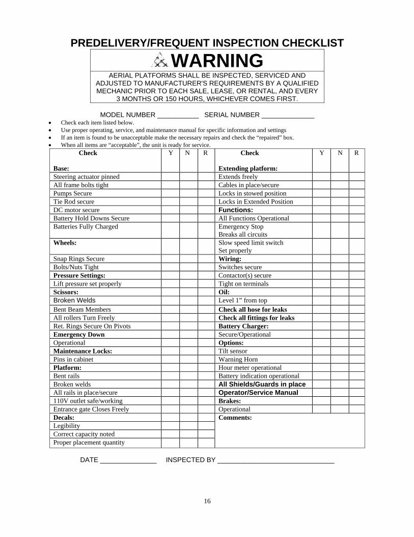
PREDELIVERY/FREQUENT INSPECTION CHECKLIST
WARNING
AERIAL PLATFORMS SHALL BE INSPECTED, SERVICED AND ADJUSTED TO MANUFACTURER'S REQUIREMENTS BY A QUALIFIED MECHANIC PRIOR TO EACH SALE, LEASE, OR RENTAL, AND EVERY
3 MONTHS OR 150 HOURS, WHICHEVER COMES FIRST.
MODEL NUMBER ___________ SERIAL NUMBER ______________ Check each item listed below. Use proper operating, service, and maintenance manual for specific information and settings If an item is found to be unacceptable make the necessary repairs and check the “repaired” box. When all items are “acceptable”, the unit is ready for service.
Check Base:
Y N R Check Extending platform:
Y N R
Steering actuator pinned Extends freely All frame bolts tight Cables in place/secure Pumps Secure Locks in stowed position Tie Rod secure Locks in Extended Position DC motor secure Functions: Battery Hold Downs Secure All Functions Operational Batteries Fully Charged Emergency Stop
Breaks all circuits
Wheels: Slow speed limit switch Set properly
Snap Rings Secure Wiring: Bolts/Nuts Tight Switches secure Pressure Settings: Contactor(s) secure Lift pressure set properly Tight on terminals Scissors: Oil: Broken Welds Level 1” from top Bent Beam Members Check all hose for leaks All rollers Turn Freely Check all fittings for leaks Ret. Rings Secure On Pivots Battery Charger: Emergency Down Secure/Operational Operational Options: Maintenance Locks: Tilt sensor Pins in cabinet Warning Horn Platform: Hour meter operational Bent rails Battery indication operational Broken welds All Shields/Guards in place All rails in place/secure Operator/Service Manual 110V outlet safe/working Brakes: Entrance gate Closes Freely Operational Decals: Comments: Legibility Correct capacity noted Proper placement quantity
DATE _______________ INSPECTED BY _______________________________

17
PRESTART INSPECTION CHECKLIST
WARNING
THIS CHECKLIST MUST BE USED AT THE BEGINNING OF EACH SHIFT OR AFTER EVERY SIX TO EIGHT HOURS OF USE. FAILURE
TO DO SO COULD AFFECT THE SAFETY OF THE OPERATOR.
MODEL NUMBER __________ SERIAL NUMBER ______________
1. Keep inspection records up-to-date. 2. Record and report all discrepancies to your supervisor. 3. A dirty machine cannot be properly inspected.
Y-Yes/Acceptable N-No/Unacceptable R-Repaired
Description Y N RVisually inspect all machine components for missing parts and obvious damage including torn or loose hoses, hydraulic fluid leaks, torn, frayed, or disconnected wires, and bent structural members. Replace components as necessary.
Check the hydraulic fluid level with the platform fully lowered.
Check the tires for damage. Check wheel axle bolts for tightness.
Check the hoses and the cables for worn areas or chafing. Replace if necessary.
Check the platform rails and safety gate for damage. Look at the gate and make sure it closes properly.
Check that all snap rings are secure in grooves on pivot pins.
Check that warning and instructional labels are legible and secure.
Inspect the platform control. Ensure that load capacity is clearly marked.
Check the base controls for proper operation. Check all switches and push buttons for proper operation.
Check the platform controls for proper operation. Check all switches and push buttons, as well as ensuring that the drive controller returns to neutral.
Check that pothole guards deploy when platform is raised.
Check that ANSI/SIA Manual of Responsibilities, Operators/Safety Manual, and AEM Handbook are located in manual box
DATE _______________ INSPECTED BY ____________________________
18
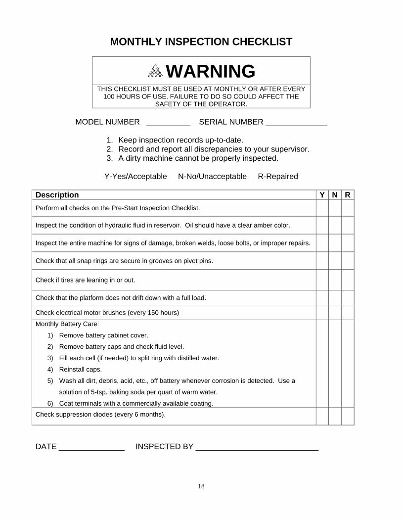
MONTHLY INSPECTION CHECKLIST
WARNING
THIS CHECKLIST MUST BE USED AT MONTHLY OR AFTER EVERY 100 HOURS OF USE. FAILURE TO DO SO COULD AFFECT THE
SAFETY OF THE OPERATOR.
MODEL NUMBER __________ SERIAL NUMBER ______________
1. Keep inspection records up-to-date. 2. Record and report all discrepancies to your supervisor. 3. A dirty machine cannot be properly inspected.
Y-Yes/Acceptable N-No/Unacceptable R-Repaired
Description Y N R
Perform all checks on the Pre-Start Inspection Checklist.
Inspect the condition of hydraulic fluid in reservoir. Oil should have a clear amber color.
Inspect the entire machine for signs of damage, broken welds, loose bolts, or improper repairs.
Check that all snap rings are secure in grooves on pivot pins.
Check if tires are leaning in or out.
Check that the platform does not drift down with a full load.
Check electrical motor brushes (every 150 hours)
Monthly Battery Care:
1) Remove battery cabinet cover.
2) Remove battery caps and check fluid level.
3) Fill each cell (if needed) to split ring with distilled water.
4) Reinstall caps.
5) Wash all dirt, debris, acid, etc., off battery whenever corrosion is detected. Use a
solution of 5-tsp. baking soda per quart of warm water.
6) Coat terminals with a commercially available coating.
Check suppression diodes (every 6 months).
DATE _______________ INSPECTED BY ____________________________

19
Lubrication Item Specification Frequency Front Wheels (For HB1030 Models With Roller Bearings) No lubrication necessary for Models with DU Bearings
Light Grease Quarterly
Troubleshooting If unit is not functioning, check the following:
Battery is connected. Key Switch is turned on. Emergency stop switches are reset. Enable Switch is held in for driving.
Drive Control Board LED Diagnostics Programmer Display LED Code Explanation Possible Cause
THERMAL CUTBACK ¤ ¤ Over-/under-temp. cutback
1. Temperature >92º C or <-25ºC. 2. Excessive load on vehicle. 3. Electromagnetic brake not releasing
properly.
THROTTLE FAULT 1 ¤ ¤¤ Pot high or pot low signal out of range
1. Throttle input wire open or shorted. 2. Throttle pot device. 3. Wrong type selected
SPD LIMIT POT FAULT ¤ ¤¤¤ Speed limit pot fault 1. Speed limit pot wire(s) broken or
shorted. 2. Broken speed limit pot.
LOW BATTERY VOLTAGE ¤ ¤¤¤¤ Battery voltage too low 1. Battery voltage <17 volts. 2. Bad connection at battery or
controller.
OVERVOLTAGE ¤ ¤¤¤¤¤ Battery voltage too high
1. Battery voltage >36 volts. 2. Vehicle operating with charger
attached. 3. Intermittent battery connection.
MAIN OFF FAULT ¤¤ ¤ Main cont. Off fault 1. Main contactor drive failed open.
MAIN CONT WELDED ¤¤ ¤¤ Main contactor did not open 1. Main contactor welded. 2. Main contactor driver fault. 3. Brake coil resistance too high.
MAIN CONT DNC ¤¤ ¤¤¤ Main contactor did not close 1. Main contactor stuck open. 2. Main contactor driver fault. 3. Brake coil resistance too high.
MAIN ON FAULT ¤¤ ¤¤¤¤ Main cont. driver On fault 1. Main contactor driver failed closed.
PROC/WIRING FAULT ¤¤¤ ¤ HPD fault present > 100 sec. 1. Misadjusted throttle. 2. Broken throttle pot or throttle
mechanism.
BRAKE ON FAULT ¤¤¤ ¤¤ Brake on fault 1. Electromagnetic brake driver shorted. 2. Electromagnetic brake coil open.
PRECHARGE FAULT ¤¤¤ ¤¤¤ Brake off fault 1. Controller failure. 2. Low battery voltage.
BRAKE OFF FAULT ¤¤¤ ¤¤¤¤ Precharge fault 1. Electromagnetic brake driver open. 2. Electromagnetic brake coil shorted.
HPD ¤¤¤ ¤¤¤¤¤ HPD fault 1. Improper sequence of throttle and
KSI, push, or inhibit inputs. 2. Misadjusted throttle pot.
CURRENT SENSE FAULT ¤¤¤¤ ¤ Current sense voltage fault 1. Short in motor or in motor wiring. 2. Controller failure.
HW FAILSAFE ¤¤¤¤ ¤¤ Motor voltage fault
1. Motor voltage does not correspond to throttle request.
2. Short in motor or in motor wiring. 3. Controller failure.
EEPROM FAULT ¤¤¤¤ ¤¤¤ EEPROM fault 1. EEPROM failure or fault.
POWER SECTION FAULT ¤¤¤¤ ¤¤¤¤ Output section fault 1. EEPROM failure or fault. 2. Short in motor or motor wiring. 3. Controller failure.

20
Troubleshooting Table Problem Possible Cause Solution
Pump will not operate.
Key switch in OFF position. Turn key switch to ON position. Emergency stop activated. Pull out emergency stop button. Battery not sufficiently charged. Fully charge battery. Electrical circuitry defective. Repair or replace wiring as needed.
Defective pump motor. Remove pump assembly and obtain replacement pump from factory.
Pump operates; lift will not ascend.
Hydraulic fluid level low. With platform lowered, fill pump reservoir to 1" below top of reservoir.
Dump valve on pump stuck open. Flush valve by simultaneously pressing the up switch at base and the down switch on platform control for 30 sec.
Emergency down valve open. Close emergency down valve.
Ascent speed slow or erratic.
Battery not sufficiently charged. Fully charge battery. Emergency down valve open. Close emergency down valve Loose electrical connection. Inspect & ensure all connections are secure. Momentary short in wiring. Repair or replace wiring as needed.
Foreign matter lodged in dump valve.
Flush valve by simultaneously pressing the up switch at base and the down switch on platform control for 30 sec. If problem continues, replace dump valve.
Bent structural member(s). Make arrangements w/ factory to have member(s) replaced.
Restriction in hydraulic hose. Replace defective hydraulic hose. Gears in pump worn or defective. Return pump assembly to factory for replacement.
Descent speed slow.
Obstruction in hydraulic hose. Replace defective hydraulic hose.
Obstruction in dump valve.
Flush valve by simultaneously pressing the up switch at base and the down switch on platform control for 30 sec. If problem continues, replace dump valve.
Unit will not descend.
Key switch on OFF position. Turn key to ON position. Emergency stop activated. Pull out emergency stop button. Battery not sufficiently charged. Fully charge battery. Loose electrical connection. Inspect & ensure all connections are secure. Faulty dump solenoid. Replace dump solenoid.
Actuated velocity fuse.
Check for hydraulic leak and repair as needed. Reset velocity fuse by elevating platform w/ hydraulic pump. Check that the unit has proper hydraulic fluid. Replace if needed.
Unit creeps down.
Emergency down valve open. Close emergency down valve.
Foreign matter lodged in dump valve.
Flush valve by simultaneously pressing the up switch at base and the down switch on platform control for 30 sec.
Defective down valve. Replace down valve.
Damaged seal in hydraulic cylinder.
Replace hydraulic seals in cylinder w/ seal kit available from factory (KIT-240). Note: If walls inside cylinder are scratched or pitted, cylinder must be replaced.
No Drive, Steer or Lift Functions
Key Switch is off. Turn on key switch. E-Stop is on. Pull E-Stop button out. Fuse at Pump Blown Replace with 20 Amp AGC Fuse. Tilt Sensor Disconnected. Replace Tilt Sensor.
21
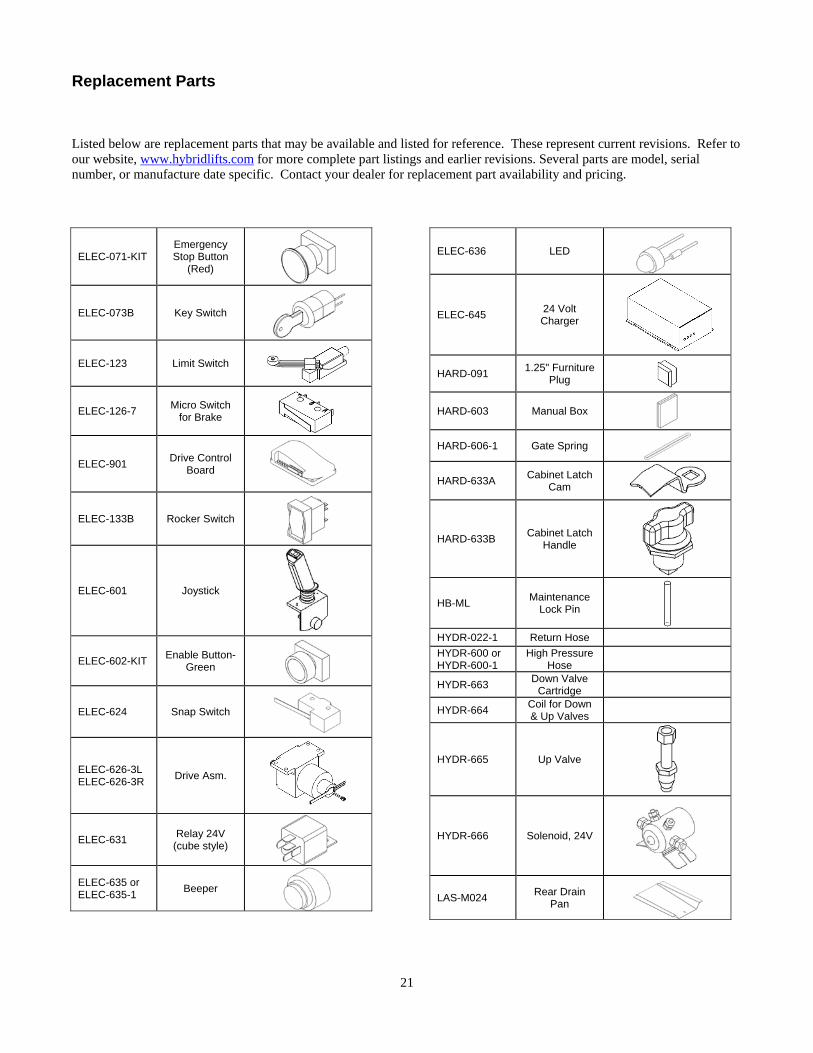
Replacement Parts Listed below are replacement parts that may be available and listed for reference. These represent current revisions. Refer to our website, www.hybridlifts.com for more complete part listings and earlier revisions. Several parts are model, serial number, or manufacture date specific. Contact your dealer for replacement part availability and pricing.
ELEC-071-KIT Emergency Stop Button
(Red)
ELEC-073B Key Switch
ELEC-123 Limit Switch
ELEC-126-7 Micro Switch
for Brake
ELEC-901 Drive Control
Board
ELEC-133B Rocker Switch
ELEC-601 Joystick
ELEC-602-KIT Enable Button-
Green
ELEC-624 Snap Switch
ELEC-626-3L ELEC-626-3R
Drive Asm.
ELEC-631 Relay 24V
(cube style)
ELEC-635 or ELEC-635-1
Beeper
ELEC-636 LED
ELEC-645 24 Volt Charger
HARD-091 1.25" Furniture
Plug
HARD-603 Manual Box
HARD-606-1 Gate Spring
HARD-633A Cabinet Latch
Cam
HARD-633B Cabinet Latch
Handle
HB-ML Maintenance
Lock Pin
HYDR-022-1 Return Hose
HYDR-600 or HYDR-600-1
High Pressure Hose
HYDR-663 Down Valve
Cartridge
HYDR-664 Coil for Down & Up Valves
HYDR-665 Up Valve
HYDR-666 Solenoid, 24V
LAS-M024 Rear Drain
Pan

22
LAS-M025 Front Drain
Pan
LAS-M026 Base Steer Top Cover
LAS-M078 Slide Out Channel
LAS-M079 Control Panel
Cover
LAS-M088 Drive Cover (Style Rev 1)
LAS-M089 Gate Latch
(Style Rev 1)
LAS-M092 Slide Brake
Handle
MISC-600 Aerials Manual
(green)
MISC-601 Manual of
Responsibility
SUB A1 Actuator
Assembly
SUB A11-L or SUB A11-L-1
Cover Assembly
(Control Side)
SUB A11-R-1 Cover
Assembly (Pump Side)
SUB A12 Tilt Sensor Assembly
SUB A12-10 OR SUB A12-11
Tilt Sensor Assembly
SUB A13 OR SUB A13-3
Main Wire Harness
SUB A2 or SUB A2A
Center Steer Assembly
SUB A3 8" Dual Caster
Assembly
SUB A3-1 10” Dual Caster
Assembly
SUB A7 OR SUB A7-1
Hydraulic Cylinder
Assembly
SUB A8A Lower Control
Panel Assembly
SUB A9 Joystick Box
Assembly
SUPO-602 Hybrid Manual
WHEE-600-1 10” Drive
Wheel (Rear) (for 1” axle)
WHEE-044 8" Wheel (Front)
WHEE-603 10”: Wheel
(Front)

23
Note: Parts may vary from photograph for different models.
HB-WC-SO-D Slide-Out Assembly
HB-WC-R-D W/C Right Assembly HB-WC-L-D
W/C Left Assembly
HB-WC-G Gate Assembly
MISC-600 Aerial Platform Manual (Inside)
MISC-601 Manual of Responsibilities (Inside)
HARD-603 Manual Box
HARD-092 Square Plug
SUB A11-R-1 Cabinet Cover-Pump Side LAS-M026
Steer Top Covers
SUB A11-L-1 Cabinet Cover-Control Side
LAS-M061-PC & LAS-M062-PC
Battery Hold Down
HYDR-050-1 Pump
ELEC-047 Battery

24
Note: Parts may vary from photograph for different models.
HB-P Platform Assembly
SUB A8A Control Panel Assembly
ELEC-071 Push/Pull Button
ELEC-073B Key Switch
ELEC-133B Rocker Switch
ELEC-610 Voltmeter/Hour Meter
SUB A12 (Or SUB A12-10) Level Sensor
ELEC-635 Beeper
ELEC-640 Charger
ELEC-631 Relay
ELEC-123 Limit Switch
ELEC-624 Snap Switch
SUB A9 Upper Control Box

25
Note: Parts may vary from photograph for different models.
WHEE-600 Rear Wheel (for ¾” shaft) WHEE-600-1 Rear Wheel (for 1” shaft)
SUB A3 8” Caster Assembly
WHEE-601 8” Front Wheel
HYDR-007 Hydraulic Cylinder (HB1030) HYDR-041 Hydraulic Cylinder (HB1430)
HYDR-600 Hydraulic Hose (HB1030) HYDR-601 Hydraulic Hose (HB1430)
LAS-L055 Upper Conduit
SUB A3-1 10” Caster Assembly
WHEE-603 10” Front Wheel

26
Warranty
LIMITED WARRANTY – Warranty Statement Custom Equipment, Inc. (the “Company”) warrants that all new units of equipment manufactured and sold by it conform to the Company’s latest published specifications. Also, that all purchased components and sub-assembled parts and assemblies shall be free from defect in material and/or workmanship for a period of 12 months from the date a new unit is placed into service, with the exception of batteries which are covered by the battery manufacturer for a period of ninety (90) days (pro-rated for one (1) year) on batteries. Further, that all structural components manufactured, purchased, and installed by Custom Equipment, Inc. shall be free of any defect in material and/or workmanship for a period of 60 months from the date a new unit is placed into service. If the equipment owner/end-user experiences a failure or deficiency within the specified warranty period they must promptly notify an authorized Dealer service repair facility. During the Warranty period, Custom Equipment, Inc. reserves the right to replace, repair, exchange, or to provide a new, used, or rebuilt component, assembly, sub-assembly, or weldment at their discretion, dependant upon circumstance, situation, and/or availability. For battery warranty, call the number listed on the battery for further instructions. This Warranty Policy does NOT cover damage caused by; shipment, misuse of unit (includes operation beyond Factory established limits, loads, and/or specifications), failure to properly service and maintain the unit in accordance with the Company’s manuals or Factory Service Bulletins. Custom Equipment, Inc. DOES NOT accept any responsibility for alterations or modifications to the unit, or, damages caused by any natural disasters (such as fire, flood, wind and lightning). THE PREVIOUS WARRANTY STATEMENT IS IN LIEU OF ALL OTHER WARRANTIES, EXPRESS OR IMPLIED, INCLUDING BUT NOT LIMITED TO THE IMPLIED WARRANTIES OF MERCHANTABILITY AND FITNESS FOR A PARTICULAR PURPOSE. If field repair or parts replacement is necessary on any warranted components, Custom Equipment, Inc. will reimburse Authorized Dealers for direct labor costs incurred according to the Company’s current authorized Field Service Rate (FSR) and/or any established ‘Flat Rate Guides’. Custom Equipment does not pay labor on any consumable items such as batteries, brakes, or tire wear. In no event shall the Company be liable for any indirect, incidental, consequential, or special damage (including without limitation to loss of profits, loss of revenue, cost of capital, cost of substitute equipment, downtime, examination fees, claims of third parties, and injury to person or property) based upon any claim of breach of warranty, breach of contract, negligence, strict liability in tort, or any other legal theory. This limited warranty statement recognizes the risks and limitations of product failure between Custom Equipment, Inc. and the Buyer. This written warranty is also understood to be the complete and exclusive agreement between the parties, superseding all prior agreements, oral or written and all other communications between the parties relating to the subject matter of this warranty. No employee, agent or distributor of the Company, or any other person is authorized to state or imply any additional warranties on behalf of the Company, nor to assume for the Company any other liability in connection with any of its products, unless made in writing, dated, and signed by an officer of the Company.