operation manual for automatic leveling...
TRANSCRIPT
© 11/12 Power Gear #82-L0379 Rev. 0E
Operation Manual for Automatic
Leveling Systems
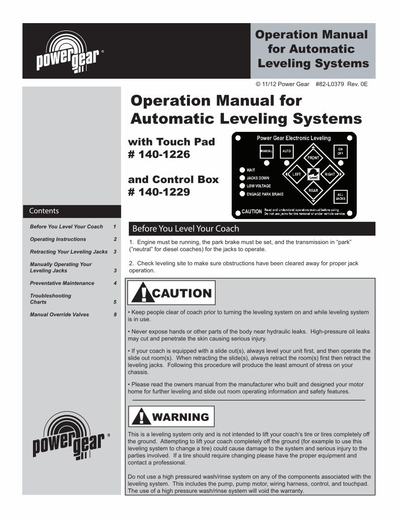
Operation Manual for Automatic Leveling Systems
Before You Level Your Coach
with Touch Pad# 140-1226
and Control Box# 140-1229
Contents
Before You Level Your Coach 1
Operating Instructions 2
Retracting Your Leveling Jacks 3
3
4
5
8
Manually Operating Your Leveling Jacks
Preventative Maintenance
TroubleshootingCharts
Manual Override Valves
1. Engine must be running, the park brake must be set, and the transmission in “park”(”neutral” for diesel coaches) for the jacks to operate.
2. Check leveling site to make sure obstructions have been cleared away for proper jackoperation.
• Keep people clear of coach prior to turning the leveling system on and while leveling systemis in use.
• Never expose hands or other parts of the body near hydraulic leaks. High-pressure oil leaksmay cut and penetrate the skin causing serious injury.
• If your coach is equipped with a slide out(s), always level your unit first, and then operate theslide out room(s). When retracting the slide(s), always retract the room(s) first then retract theleveling jacks. Following this procedure will produce the least amount of stress on yourchassis.
• Please read the owners manual from the manufacturer who built and designed your motorhome for further leveling and slide out room operating information and safety features.
This is a leveling system only and is not intended to lift your coach’s tire or tires completely off the ground. Attempting to lift your coach completely off the ground (for example to use this leveling system to change a tire) could cause damage to the system and serious injury to the parties involved. If a tire should require changing please have the proper equipment and contact a professional.
Do not use a high pressured wash/rinse system on any of the components associated with the leveling system. This includes the pump, pump motor, wiring harness, control, and touchpad. The use of a high pressure wash/rinse system will void the warranty.
CAUTION!
WARNING!
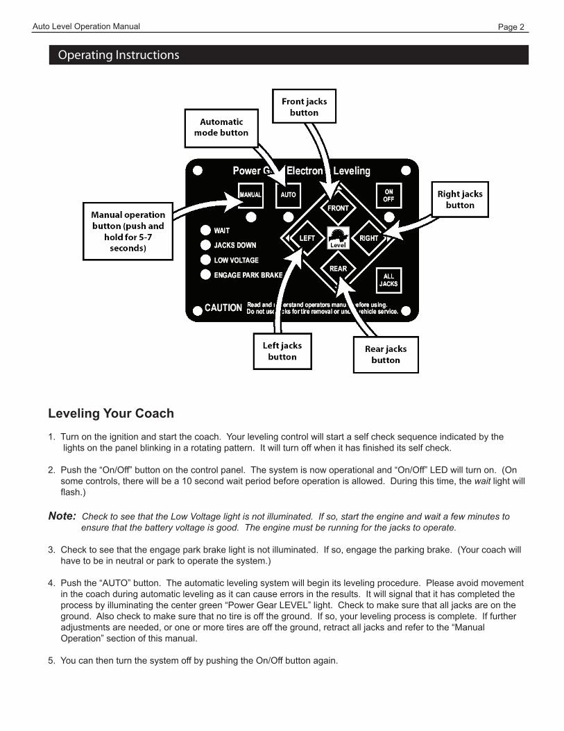
Operating Instructions
Auto Level Operation Manual Page 2
Leveling Your Coach1. Turn on the ignition and start the coach. Your leveling control will start a self check sequence indicated by the
lights on the panel blinking in a rotating pattern. It will turn off when it has finished its self check.
2. Push the “On/Off” button on the control panel. The system is now operational and “On/Off” LED will turn on. (Onsome controls, there will be a 10 second wait period before operation is allowed. During this time, the wait light willflash.)
Note: Check to see that the Low Voltage light is not illuminated. If so, start the engine and wait a few minutes to ensure that the battery voltage is good. The engine must be running for the jacks to operate.
3. Check to see that the engage park brake light is not illuminated. If so, engage the parking brake. (Your coach willhave to be in neutral or park to operate the system.)
4. Push the “AUTO” button. The automatic leveling system will begin its leveling procedure. Please avoid movementin the coach during automatic leveling as it can cause errors in the results. It will signal that it has completed theprocess by illuminating the center green “Power Gear LEVEL” light. Check to make sure that all jacks are on theground. Also check to make sure that no tire is off the ground. If so, your leveling process is complete. If furtheradjustments are needed, or one or more tires are off the ground, retract all jacks and refer to the “ManualOperation” section of this manual.
5. You can then turn the system off by pushing the On/Off button again.

Auto Level Operation Manual Page 3
Manually Operating Your Leveling Jacks
Retracting Your Leveling Jacks
1. Turn on the ignition and start the coach.
2. Turn on the system by pushing the “On/Off” button. The system is now operational and the “On/Off” LED willturn on.
3. Push the “RETRACT-ALL JACKS” button. When the “JACKS DOWN” light turns off, visually check to make surethat all jacks have fully retracted. If so, your coach leveling system is ready to travel.
Leveling Your Coach
There are certain conditions where manually leveling your coach may be desirable. Conditions where large amounts of side to side leveling are necessary or when one or more tires are off the ground at the end of the auto-level sequence, it may work better using the manual leveling procedures that follow:
1. Turn on the ignition and start the coach.
2. Push the “On/Off” button to turn on the system.
3. Push and hold the “MAN” button for 5-7 seconds in order for the system toswitch to the manual mode. It will signal that it is in the manual mode when thelight under the “MAN” button is illuminated.
4. Push “FRONT” button until the front of the coach rises at least 3”. This isimportant and necessary to allow the coach to pivot when leveling side to side.If there is insufficient jack stroke to lift the front of the coach at least 3 inches,the coach will have to be moved to an area with less front to back slope, or aweight distribution block will have to be placed under the jack.
5. Push the “REAR” button until jacks contact the ground.
6. Level the coach from front to rear by pushing the “REAR” button if the lightunder the “REAR” button is illuminated. If the light is illuminated above the“FRONT JACKS” button, push the “FRONT” button. In either case, keep button
depressed until the green center “LEVEL ” light is illuminated, or both front andrear lights are dark.
7. Level the coach from side to side by pushing the “RIGHT” button if the lightbeside the”RIGHT” button is illuminated. If the light beside the ”LEFT” button isilluminated, push the “LEFT” button until the “LEVEL” light is illuminated.
8. Repeat steps 6 and 7 if needed.
9. Turn power off to leveling system by pushing “ON/OFF” button.
10. Visually inspect jack to ensure all pads are touching ground. Should one ofthe rear jacks not be touching the ground, press the corresponding left or rightrear jack buttons to lower the appropriate jack to the ground. Never lift thewheels off the ground to level the coach. This can lead to an unsafe conditionand damage to the leveling system or coach.
11. If a level condition cannot be reached or one or more tires are off the ground at the completionof leveling, retract the leveling jacks and move the coach to a different location or change itsorientation to achieve a more level starting position and repeat steps 1 through 10.
NOTE!
NOTE!
The right and left rear jacks are used to level the coach side to side. Pushing the “LEFT” button on the control panel will extend the left rear jack. Pushing the “RIGHT” button on the control will extend the right rear jack.
If the “Wait” LED is ever flashing by itself, it means the control is busy and you cannot operate the jacks. After a short period of time (from 5 to 30 seconds), the “WAIT” LED will go off again, and you can resume operation as normal.
12. If a level condition cannot be obtained with the previous steps, level the coach as much aspossible while maintaining tire contact with the ground.
Auto Level Operation Manual Page 4
Preventative Maintenance
1. Check and/or fill the reservoir with the jacks and room(s) in the fully retracted position, each month. The fluid should be one inch onto the dipstick (on models so equipped) or to the bottom of the fill port on models without dipsticks.
2. Change fluid every 24 months.
3. Inspect and clean all hydraulic pump electrical connections every 12 months.
4. Remove dirt and road debris from jacks as needed.
5. If jacks are down for extended periods, it is recommended to spray exposed leveling jack chrome rods with a silicone lubricant every 5 to 7 days for protection.
6. If your coach is located in a salty environment (within 60 miles of coastal), it is recommended to spray the rods every 2 to 3 days with a silicone lubricant.
7. Grease the fitting on the bottom of each jack cylinder with Lithium grease every20-30 uses.
8. Do not use a high pressured wash/rinse system on of the components associated with the leveling system. This includes the pump, pump motor, wiring harness, control, and touch pad. The use of a high pressure wash/rinse system will void the warranty.
Recommended Hydraulic Fluids for Your Hydraulic Pump
The fluids listed here are acceptable to use in your pump assembly. Contact coach manufacturer or selling dealer for information about what specific fluid was installed in your system.
• It is not recommended that hydraulic fluid and automatic transmission fluids bemixed in the reservoir.
• In most applications, Type A automatic transmission fluid (ATF, Dexron III, etc.,)will work satisfactorily. Mercon V is also recommended as an alternative fluid forPower Gear hydraulic systems.
• If operating in cold temperatures (less than -10° F), the jacks may extend andretract slowly.
• For cold weather operation, fluid specially-formulated for low temperatures maybe desirable. Mobil DTE 11M, Texaco Rando HDZ-15HVI, Kendall Hyden GlacialBlu, or any Mil. Spec. H5606 hydraulic fluids are recommended for cold weatheroperation.
Please consult factory before using any other fluids than those specified here.
Auto Level Operation Manual Page 5
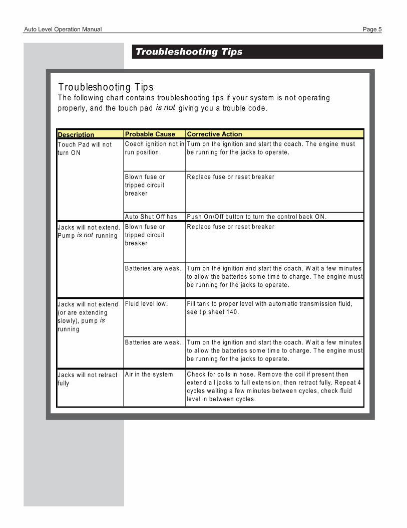
Troubleshooting Tips
Probable Cause Corrective ActionC oach ign ition no t in run pos ition .
T urn on the ign ition and s ta rt the coach. T he eng ine m ust be runn ing fo r the jacks to opera te .
B low n fuse or tripped c ircu it b reaker
R ep lace fuse or rese t b reaker
A uto S hut O ff has occurred (b /c 4
P ush O n/O ff bu tton to tu rn the contro l back O N .B low n fuse or tripped c ircu it b reaker
R ep lace fuse or rese t b reaker
B atte ries are w eak . T urn on the ign ition and s ta rt the coach. W ait a few m inutes to a llow the ba tte ries som e tim e to charge. T he eng ine m ust be runn ing fo r the jacks to opera te .
F lu id leve l low . F ill tank to p roper leve l w ith au tom atic transm iss ion flu id , see tip sheet 140.
B atte ries are w eak . T urn on the ign ition and s ta rt the coach. W ait a few m inutes to a llow the ba tte ries som e tim e to charge. T he eng ine m ust be runn ing fo r the jacks to opera te .
A ir in the sys tem C heck fo r co ils in hose. R em ove the co il if p resent then ex tend a ll jacks to fu ll ex tens ion , then re trac t fu lly. R epeat 4 cyc les w a iting a few m inutes be tw een cyc les , check flu id leve l in be tw een cyc les .
Troub leshooting T ipsT he fo llow ing chart con ta ins troub leshoo ting tips if your system is no t opera ting p roperly, and the touch pad is not g iv ing you a troub le code .
T ouch P ad w ill no t tu rn O N
Jacks w ill no t ex tend. P um p is not runn ing
Description
Jacks w ill no t ex tend (o r a re ex tend ing s low ly), pum p is runn ing
Jacks w ill no t re trac t fu lly
Auto Level Operation Manual Page 6
Troubleshooting Tips, cont’d
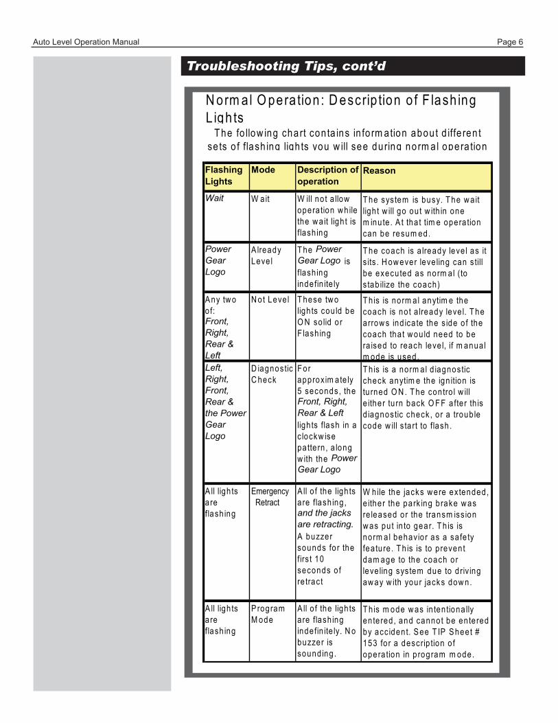
Flashing Lights
Mode Description of operation
Wait W ait W ill no t a llow opera tion w h ile the w a it ligh t is flash ing
Power Gear Logo
A lready Leve l
T he Power Gear Logo is flash ing indefin ite ly
A ny tw o o f:Front, Right, Rear & Left
N ot Leve l T hese tw o ligh ts cou ld be O N so lid o r F lash ing
Left, Right, Front, Rear & the Power Gear Logo
D iagnostic C heck
For approx im ate ly 5 seconds, the Front, Right, Rear & Left ligh ts flash in a c lockw ise pa tte rn , a long w ith the Power Gear Logo
A ll ligh ts a re flash ing
Emergency Retract
A ll o f the ligh ts a re flash ing , and the jacks are retracting. A buzzer sounds fo r the firs t 10 seconds o f re trac t
A ll ligh ts a re flash ing
P rogram M ode
A ll o f the ligh ts a re flash ing indefin ite ly. N o buzzer is sound ing .
T h is is norm al anytim e the coach is no t a lready leve l. T he arrow s ind ica te the s ide o f the coach tha t w ou ld need to be ra ised to reach leve l, if m anua l m ode is used.T h is is a norm al d iagnostic check anytim e the ign ition is tu rned O N . T he contro l w ill e ither tu rn back O FF a fte r th is d iagnostic check , o r a troub le code w ill s ta rt to flash .
W hile the jacks w ere ex tended, e ither the park ing brake w as re leased or the transm iss ion w as pu t in to gear. T h is is norm al behavio r as a sa fe ty fea ture . T h is is to p revent dam age to the coach or leve ling sys tem due to d riv ing aw ay w ith your jacks dow n.
T h is m ode w as in ten tiona lly en tered , and cannot be en tered by acc ident. S ee T IP S heet # 153 fo r a descrip tion o f opera tion in p rogram m ode.
N orm al O pera tion : D escrip tion o f F lash ing L igh ts
Reason
T he sys tem is busy. T he w a it ligh t w ill go ou t w ith in one m inute . A t tha t tim e opera tion can be resum ed.
T he coach is a lready leve l as it s its . H ow ever leve ling can s till be executed as norm al (to s tab ilize the coach)
T he fo llow ing chart con ta ins in fo rm ation abou t d iffe ren t se ts o f flash ing ligh ts you w ill see during norm a l opera tion
Auto Level Operation Manual Page 7
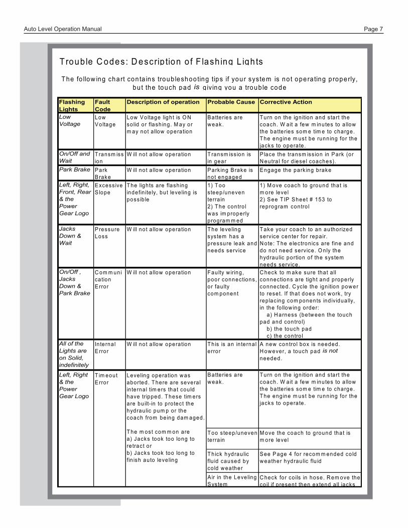
Flashing Lights
Fault Code
Description of operation Probable Cause Corrective Action
Low Voltage
Low V o ltage
Low V o ltage ligh t is O N so lid o r flash ing . M ay or m ay no t a llow opera tion
B atte ries are w eak .
T urn on the ign ition and s ta rt the coach. W ait a few m inutes to a llow the ba tte ries som e tim e to charge. T he eng ine m ust be runn ing fo r the jacks to opera te .
On/Off and Wait
T ransm ission
W ill no t a llow opera tion T ransm iss ion is in gear
P lace the transm iss ion in P ark (o r N eutra l fo r d iese l coaches).
Park Brake P ark B rake
W ill no t a llow opera tion P ark ing B rake is no t engaged
E ngage the park ing brake
Left, Right, Front, Rear & the Power Gear Logo
E xcess ive S lope
T he ligh ts a re flash ing indefin ite ly, bu t leve ling is poss ib le
1) T oosteep/uneventerra in2) T he contro lw as im properlyprogram m ed
1) M ove coach to g round tha t ism ore leve l2 ) S ee T IP S heet # 153 toreprogram contro l
Jacks Down & Wait
P ressure Loss
W ill no t a llow opera tion T he leve ling sys tem has a pressure leak and needs service
T ake your coach to an au thorized service center fo r repa ir.N ote : T he e lec tron ics a re fine and do no t need service . O n ly the hydrau lic portion o f the sys tem needs service .
On/Off , Jacks Down & Park Brake
C om m unica tion E rror
W ill no t a llow opera tion Fau lty w iring , poor connections, o r fau lty com ponent
C heck to m ake sure tha t a ll connections are tigh t and properly connected . C yc le the ign ition pow er to rese t. If tha t does no t w ork , try rep lac ing com ponents ind iv idua lly, in the fo llow ing order:
a ) H arness (be tw een the touchpad and contro l)
b ) the touch padc) the contro l
All of the Lights are on Solid, indefinitely
In te rna l E rror
W ill no t a llow opera tion T h is is an in te rna l e rro r
A new contro l box is needed. H ow ever, a touch pad is not needed.
B atte ries are w eak .
T urn on the ign ition and s ta rt the coach. W ait a few m inutes to a llow the ba tte ries som e tim e to charge. T he eng ine m ust be runn ing fo r the jacks to opera te .
T oo s teep/uneven te rra in
M ove the coach to g round tha t is m ore leve l
T h ick hydrau lic flu id caused by co ld w eather
S ee P age 4 fo r recom m ended co ld w eather hydrau lic flu id
T roub le C odes: D escrip tion o f F lash ing L igh ts
Left, Right & the Power Gear Logo
T im eout E rror
Leve ling opera tion w as aborted . T here are severa l in te rna l tim ers tha t cou ld have tripped. T hese tim ers are bu ilt-in to p ro tec t the hydrau lic pum p or the coach from be ing dam aged.
T he m ost com m on area) Jacks took too long tore trac t o rb) Jacks took too long tofin ish au to leve ling
A ir in the Leve ling S ystem
C heck fo r co ils in hose. R em ove the co il if p resent then ex tend a ll jacks
T he fo llow ing chart con ta ins troub leshoo ting tips if your system is no t opera ting p roperly, bu t the touch pad is g iv ing you a troub le code

Auto Level Operation Manual Page 8
Manual Override ValvesIn case of a loss of power at the pump assembly, the manual override valves (MOV’s) can be used to retract the leveling jacks. Not all Power Gear leveling system pumps have manual override valves. Power units for double acting systems that have manual override valves have flexible rubber caps on the valves and a hex override nut under the button cap on the electric motor.
To use the MOV’s:
1. Remove the button cap from the end of the electric motor. First remove the two Phillips head screws from the top ofthe motor. The button cap can now be removed from the electric motor. You should now see a 7/16” override nut on theend of the electric motor shaft.
2. After verifying all personnel and tools are clear of the press the rubber cap on the valvefor the front legs valve. The front end of the coach will start to descend. Only allow thecoach to descend for 2 inches.
3. Push and hold the rubber cap on the Roadside Rear valve. Allow the coach to descendfor 2 inches.
4. Push and hold the rubber cap on the Curbside Rear valve. Allow the coach to descendfor 2 inches.
5. Repeat procedures 2-4 until the weight of the coach is transferred off the jacks and ontothe suspension and tires.
Care must be taken during the manual retraction of jacks to prevent bodily injury or death. The next step will allow fluid to transfer from the legs to the reservoir. This procedure will allow the coach to descend. Keep all personnel and equipment clear of the coach. Make sure no one is under the coach prior to this procedure. Do not have any body parts or equipment positioned such that the coach will descend on it.
6. This procedure will retract the front legs. Using a 7/16” socket attached to a drill, spin the override nut clockwisewhile holding the button on the front legs valve. Stop when the legs are fully retracted.
7. This procedure will retract the roadside rear leg. After the front legs are retracted, press the button on the roadsiderear leg valve and spin the override nut clockwise. Stop when the leg is fully retracted.
8. This procedure will retract the curbside rear leg. After the front legs are retracted, press the button on the curbsiderear leg valve and spin the override nut clockwise. Stop when the leg is fully retracted.
9. Replace the button cap on the electric motor and securely tighten the Phillips head screws.
WARNING!