operation manual erv (energy recovery … français español models (ceiling mounted duct type)...
TRANSCRIPT

English
Français
Español
MODELS(Ceiling mounted duct type)
VAM300GVJUVAM470GVJUVAM600GVJUVAM1200GVJU
OPERATION MANUAL
ERV (Energy Recovery Ventilator)
00_CV_3P034927-7M.fm Page 1 Monday, June 20, 2011 1:25 PM

ERV; Energy Recovery VentilatorBefore using the DAIKIN ERV, be sure to read this operation manual thoroughly. If you have any prob-lem or malfunction, refer to this operation manual. Keep this manual for your future reference.This manual should be left with the equipment owner.
ERV; Ventilateur récupérateur d’énergieAvant d’utiliser le ERV DAIKIN, assurez-vous de lire ce manuel d’instructions. Si vous rencontrez un problèmeou un mauvais fonctionnement, reportez-vous à ce manuel.Conserver ce manuel pour référence future.Ce manuel devrait être remis au propriétaire de l’équipement.
ERV; Ventilador de Recuperación de Energía
Antes de usar el DAIKIN ERV, asegúrese de leer este manual de operación completamente. Si usted encuentra algún problema o mal funcionamiento, refiérase a este manual de operación. Guarde este manual para referencia futura. Este manual debe permanecer con el propietario del equipo.
ERV
00_CV_3P034927-7M.fm Page 2 Monday, June 20, 2011 1:25 PM
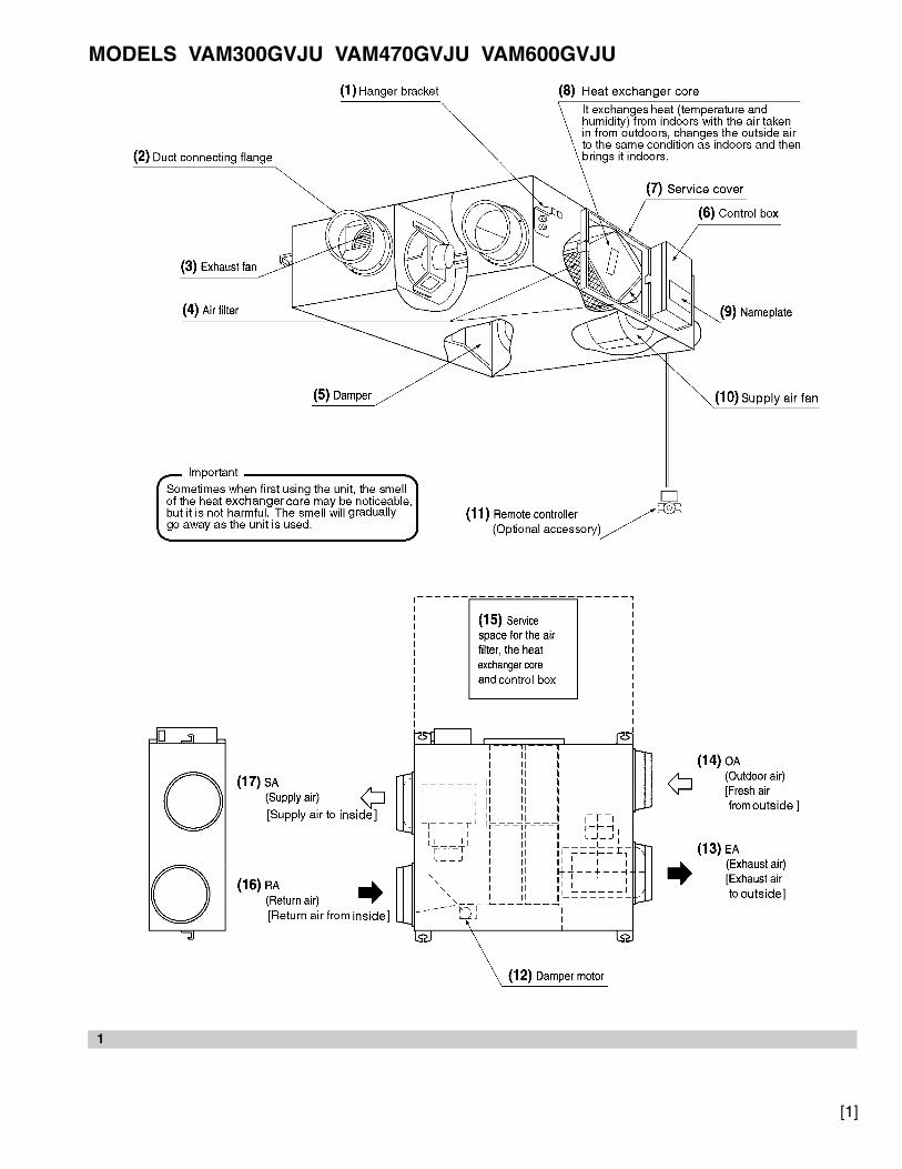
MODELS VAM300GVJU VAM470GVJU VAM600GVJU
1
[1]
00_CV_3P034927-7M.fm Page 3 Monday, June 20, 2011 1:25 PM

MODEL VAM1200GVJU(1) Hanger bracket
(2) Duct connecting flange
(3) Exhaust fan
(5) Damper
(4) Air filter
(8) Heat exchanger core
(11) Remote controller (Optional accessory)
(7) Service cover
(6) Control box
(9) Nameplate
(10) Supply air fan
It exchanges heat (temperature and humidity) from indoors with the air taken in from outdoors, changes the outside air to the same condition as indoors and then brings it indoors.
Sometimes when first using the unit, the smell of the heat exchanger core may be noticeable, but it is not harmful. The smell will gradually go away as the unit is used.
Important
(17) SA(Supply air)[Supply air to inside]
(15) Service space for the airfilter, the heat exchanger coreand control box
(14) OA(Outdoor air)[Fresh air from outside]
(13) EA(Exhaust air)[Exhaust air to outside]
(16) RA(Return air)[Return air from inside]
(12) Damper motor
1
[2]
00_CV_3P034927-7M.fm Page 4 Monday, June 20, 2011 1:25 PM
MODELS VAM300GVJU - 600GVJU MODEL VAM1200GVJU
MODELS VAM300GVJU - 600GVJU MODEL VAM1200GVJU
• Independent system • Centralized systemERV unit
Remote controller
Centralizedcontroller
ERV unit
Remote controller
Remote controller
Indoor unit ERV unit
• Interlocking system with VRV or SkyAir system
Remote controller
2
3
4
[3]
00_CV_3P034927-7M.fm Page 5 Monday, June 20, 2011 1:25 PM

5 6
7
[4]
00_CV_3P034927-7M.fm Page 6 Monday, June 20, 2011 1:25 PM

English 1
VAM300GVJUVAM470GVJUVAM600GVJUVAM1200GVJU
ERV (Energy Recovery Ventilator) Operation manual
CONTENTSILLUSTRATIONS.....................................................[1]~[4]
1. SAFETY CONSIDERATIONS .........................................12. WHAT TO DO BEFORE OPERATION ...........................33. OPERATION PROCEDURE ...........................................54. MAINTENANCE (for a qualified service person only) .....85. TROUBLE SHOOTING ...................................................96. AFTER-SALES SERVICE .............................................10
1. SAFETY CONSIDERATIONSRead these SAFETY CONSIDERATIONS for Operations carefully before installing the ERV unit. After completing the installation, make sure that the unit operates properly during a test run. Instruct the customer on how to operate and maintain the unit.Inform the customer that this Operation Manual should be kept with the Installation Manual for future reference.Meanings of DANGER, WARNING, CAUTION and NOTE Sym-bols:
DANGER .......... Indicates an imminently hazardous situa-tion which, if not avoided, will result in death or serious injury.
WARNING......... Indicates a potentially hazardous situation which, if not avoided, could result in death or serious injury.
CAUTION.......... Indicates a potentially hazardous situation which, if not avoided, may result in minor or moderate injury. It may also be used to alert against unsafe practices.
NOTE ................ Indicates situations that may result in equipment or property-damage accidents only.
DANGER
• Do not install the unit in an area where flammable mate-rials are present due to risk of explosion resulting in serious injury or death.
• Any abnormalities in the operation of the unit such as smoke or fire could result in severe injury or death. Turn off the power and contact your dealer immediately.
• Safely dispose of the packing materials. Packing materi-als, such as nails, other metal or wooden parts, may cause stabs or other injuries.
• Tear apart and throw away plastic packaging bags so that children will not play with them. Children playing with plastic bags face the danger of death by suffoca-tion.
WARNING
• Contact your dealer for repair and maintenance. Improper repair and maintenance may result in electric shock and fire. Only use accessories made by Daikin that are specifically designed for use with the equipment and have them installed by a professional.
• Contact your dealer to move and reinstall the unit. Incomplete installation may result in water leakage, elec-tric shock and fire.
• Never let the unit or the remote controller get wet. Water can cause an electric shock or a fire.
• Never use flammable spray such as hair spray, lacquer, or paint near the unit. Flammable spray may cause a fire.
• When a fuse blows out, never replace it with one of incorrect ampere ratings or different wires. Always replace any blown fuse with a fuse of the same specifi-cation.
• Never inspect or service the unit by yourself. Contact a qualified service person to perform this work.
• Turn off all electrical power before doing any mainte-nance to avoid the risk of serious electric shock; never sprinkle or spill water or liquids on the unit.
• Do not touch the switch with wet fingers. Touching a switch with wet fingers can cause electric shock.
• Do not allow children to play on or around the unit to pre-vent injury.
• Do not put a finger or other objects into the air inlet or air outlet. The fan is rotating at high speed and will cause injury.
• Check the unit foundation for damage on a continuous basis, especially if it has been in use for a long time. If left in a damaged condition the unit may fall and cause injury.
• Placing a flower vase or other containers with water or other liquids on the unit could cause electric shock or fire if a spill occurs.
• Never touch the internal parts of the controller. Do not remove the front panel because some parts inside are dangerous to touch. To check and adjust internal parts, contact your dealer.
• Be sure to establish a ground connection.Do not ground the unit to an utility pipe, arrester or tele-phone earth. Incomplete ground may cause electric shock or fire. A high surge current from lightning or other sources may cause damage to the unit.
• Be sure to install a ground fault circuit interrupter.Failure to install a ground fault circuit interrupter may result in electric shocks or fire.
• Consult your dealer if the ERV unit submerges owing to a natural disaster, such as a flood or typhoon.Do not operate the ERV unit in that case, or otherwise a malfunction, electric shock or fire may result.
01_EN_3P034927-7M.fm Page 1 Thursday, June 16, 2011 9:59 AM

2 English
• Do not start or stop operating the ERV unit with the power supply breaker turned ON or OFF.Otherwise, fire or water leakage may result.Furthermore, the fan will rotate abruptly if power failure compensation is enabled, which may result in injury.
• Do not change operations roughly. It can result not only in malfunction but also failure of switches or relays in the unit.
• Turn off the power supply when the unit is not to be used for long period of time.Otherwise, the unit may get hot or catch on fire due to dust accumulation.
• Do not block air inlets or outlets.If the fan does not blow air throughout the entire room, it may cause oxygen deficiency leading to bad health con-dition or long-term health problems.
• Locate the outdoor air intake vent so that it does not take in exhaust air which contains combustion air, etc.Incorrect installation may cause a loss of oxygen in the room, leading to serious accidents.
• Install the two outdoor ducts with down slope to prevent rainwater from entering the unit.If this is not done completely, water may enter the building, damaging furniture, and cause electric shock and fire.
• Use electric insulation between the duct and the wall when using metal ducts to pass metal or wire laths or metal plating into wooden buildings.This may cause electric shock short circuits or fire.
CAUTION
• Do not use the unit for any other purposes other than ventilation. Do not use the unit for cooling precision instruments, food, plants, animals or works of art.
• Before cleaning, stop the operation of the unit by turning the power off or by pulling the supply cord out from its receptacle. Otherwise, an electric shock and injury may result.
• Do not wash the unit with excessive water. An electric shock or fire may result.
• Avoid placing the controller in a spot splashed with water. Water entering the controller may cause an elec-tric shock or damage the internal electronic parts.
• Do not operate the unit when using a room-fumigation type of insecticide. Failure to observe this could cause the chemicals to be deposited in the unit and can endanger the health of those who are hypersensitive to chemicals.
• The appliance is not intended for use by young children or infirm persons without supervision.
• The remote controller should be kept away from children so they cannot play with it.
• Consult with the installation contractor for cleaning.• Incorrect cleaning of the inside of the unit could make
the plastics parts break and cause water leakage or elec-tric shock.
• It is not good for your health to expose your body to the air flow for a long time.
• Do not allow exhaust air to enter the outdoor air intake vent.This may cause the interior of the room to become con-taminated and harming the health.
NOTE
• Never press the button of the remote controller with a hard, pointed object. The remote controller may be damaged.
• Never pull or twist the electric wire of the remote control-ler. It may cause the unit to malfunction.
• Do not place appliances that produce open flames in places that are exposed to the air flow of the unit or under the unit. It may cause incomplete combustion or deformation of the unit due to the heat.
• Do not expose the controller to direct sunlight. The LCD display can become discolored and may fail to display the data.
• Do not wipe the controller operation panel with benzene, thinner, chemical dust cloth, etc. The panel may get discol-ored or the coating can peel off. If it is heavily dirty, soak a cloth in water-diluted neutral detergent, squeeze it well and wipe the panel clean. Then wipe it with another dry cloth.
• Dismantling of the unit and additional parts should be done in accordance with the relevant local, state and national regulations.
• Do not use the unit or an air suction/discharge grille in the following places.a. Places with a mist of mineral oil, such as cutting oil.b. Locations such as coastal areas where there is a lot of
salt in the air.c. Locations such as hot springs where there is a lot of
sulfur in the air.d. Locations such as factories where the power voltage
varies a lot.e. In cars, boats, and other vehicles.f. Locations such as kitchens where oil may splatter or
where there is steam in the air.g. Locations where equipment produces electromag-
netic waves.h. Places with an acid or alkaline mist.i. Places where fallen leaves can accumulate or where
weeds can grow.j. Place subjected to much carbon black.
Carbon black attaches to air filter and heat exchanger core, making them unable to use.
• Take snow protection measures. Contact your dealer for the details of snow protection measures, such as the use of a snow protection hood.
• Do not attempt to do electrical work or grounding work unless you are licensed to do so. Consult with your dealer for electrical work and grounding work.
• Consult your dealer if the unit in operation generates unusual noise.
• Always use the air filter.If the air filter is not used, heat exchanger core will be clogged, possibly causing poor performance and subsequent failure.
• Do not operate the ERV unit in Bypass mode when the room air is under heating in winter or when the outdoor temperature is 86°F or higher.This may cause condensation to form on the main unit or on discharge grille or around air supply opening.
• Insulate the two outdoor ducts to prevent dew conden-sation (and the indoor duct as well if needed).If this is not done completely, water may enter the build-ing, damaging furniture, etc.
01_EN_3P034927-7M.fm Page 2 Thursday, June 16, 2011 9:59 AM

English 3
2. WHAT TO DO BEFORE OPERATIONThis operation manual is for the following systems with stan-dard control. Before initiating operation, contact your Daikin dealer for the operation that corresponds to your system type and mark.If your installation has a customized control system, ask your dealer for the operation that corresponds to your system.
2-1 NAMES OF PARTS (Refer to figure 1)(1) Hanger bracket(2) Duct connecting flange
(3) Exhaust fan
(4) Air filter(5) Damper
(6) Control box
(7) Service cover(8) Heat exchanger core
(9) Nameplate
(10)Supply air fan
(11)Remote controller (Optional accessory)(12)Damper motor
(13)EA Exhaust air to outside
(14)OA Outdoor air from outside(15)Service space for the air filter, the heat exchanger core and
control box.
(16)RA Return air from inside(17)SA Supply air to inside
2-2 BUTTON LOCATIONS AND DESCRIPTIONS OF REMOTE CONTROLLER
1. Operation mode selector button2. Fan speed control button3. Menu/OK button
4. Up button
5. Down button
6. Right button
7. Left button 8. On/Off button9. Operation lamp
10. Cancel button11. LCD (with backlight)
Functions other than basic operation items (i.e., On/Off, Operation mode selector, Fan speed control, and tempera-ture setpoint) are set from the menu screen.
NOTE
• Do not install the remote controller in places exposed to direct sunlight, otherwise the LCD will be damaged.
• Do not pull or twist the remote controller wire, otherwise the remote controller may be damaged.
• Do not use objects with sharp ends to press the buttons on the remote controller, otherwise damage may result.
1 Operation mode selector button• Press this button to select the operation mode of your
preference.*Available modes vary with the indoor unit model.
2 Fan speed control button• Press this button to select the fan speed of your prefer-
ence.*Available fan speeds vary with the indoor unit model.
3 Menu/OK button• Used to indicate the main menu.
For details, refer to the operation manual attached to the remote contoller.
• Used to enter the selected item.
4 Up button • Used to raise the setpoint.• The item above the current selection will be highlighted.
(The highlighted items will be scrolled continuously when the button is continuously pressed.)
• Used to change the selected item.
5 Down button • Used to lower the setpoint.• The item below the current selection will be highlighted.
(The highlighted items will be scrolled continuously when the button is continuously pressed.)
• Used to change the selected item.
6 Right button • Used to highlight the next items on the right-hand side.• Each screen is scrolled in the right-hand direction.
7 Left button • Used to highlight the next items on the left-hand side.• Each screen is scrolled in the left-hand direction.
8 On/Off button• Press this button and system will start.• Press this button again to stop the system.
9 Operation lamp (Green)• This lamp illuminates solid during normal operation.• This lamp blinks if a error occurs.
10 Cancel button• Used to return to the previous screen.
11 LCD (with backlight)• The backlight will be illuminated for approximately 30
seconds by pressing any button.• If two remote controllers are used to control a single
indoor unit, only the controller to be accessed first will have backlight functionality.
On/OffMode
FanSpeed Cancel
MenuOK
1
2 3 10
11 9 84, 5, 6, 7
01_EN_3P034927-7M.fm Page 3 Thursday, June 16, 2011 9:59 AM

4 English
NAMES AND FUNCTIONSLiquid Crystal Display• Two types of liquid crystal display (LCD) are available. The standard display is set by default.• Detailed display can be selected in the main menu.• The displayed contents of the screen vary with the operation mode of the indoor unit model. (The following display will appear when
the indoor unit is in automatic operation.)• For details, refer to the operation manual attached to the remote contoller.
[Standard display]
[Detailed Display]
1 Operation mode• Used to display the current operation mode: Cool, Heat,
Vent, Fan, Dry or Auto.
2 Fan Speed• Used to display the fan speed that is set for the indoor
unit.• The fan speed will not be displayed if the connected
model does not have fan speed control functionality.
3 Setpoint display• Used to display the setpoint for the indoor unit.• Use the Celsius/Fahrenheit item in the main menu to
select the temperature unit (Celsius or Fahrenheit).
4 Stand by for Defrost/Hot start “ ” If ventilation icon is displayed in this field:• Indicates that the energy recovery ventilator is con-
nected.
Set toCool
Heat74F
70F
Auto
This function is not available
<Standard display example>
6.Ventilation2.Fan Speed
1.Operation mode
11.Setback
7.( ) display
3.Setpoint display
4.Stand by for Defrost/Hot start
5.Message
10.Changeover controlled by the master indoor unit
9.Under centralized control
8.( ) display
AUTOERV
AIRPURIFY
CENTRALCONTROL
MASTERCONTROLLED SETBACK
STANDBY
CoolHeat
74F
70F
Room
Fr i 11:03ASet to
74F
Auto
Return Setting
14.Detailed selection
12.Air Flow Direction(Displayed only when the air conditioner is in operation.)
13.Current Day/time (12/24 hour time display)
<Detailed display example 1>
AUTOERV
AIRPURIFY
CENTRALCONTROL
MASTERCONTROLLED SETBACK
STANDBY
Auto
Return Setting
<Detailed display example 2>
No Air Flow Direction display (with no air flow direction settings)
No Fan speed display(with no fan speed control function)
No Detailed item display(with no detailed items selected)
No Clock display (when the clock has not been set)
15. ( ) display--:--
CENTRALCONTROL
MASTERCONTROLLED SETBACK
AUTOERV
AIRPURIFY STANDBY
STANDBY
01_EN_3P034927-7M.fm Page 4 Thursday, June 16, 2011 9:59 AM

English 5
5 MessageThe following messages may be displayed.“This function is not available”• Displayed for a few seconds when an operation button is
pressed and the indoor unit does not provide the corre-sponding function.
• In a remote control group, the message will not appear if at least one of the indoor units provides the corre-sponding function.
“Error: Push Menu button”“Warning: Push Menu button”• Displayed if an error or warning is detected.
“Time to clean filter”“Time to clean element”“Time to clean filter & element”• Displayed as a reminder when it is time to clean the filter
or element (heat exchange core).
6 Ventilation• Displayed when the energy recovery ventilator is con-
nected.
• Ventilation Mode icon.“ ”These icons indicate the current ventilation mode (ERV only) (AUTO, ERV, BYPASS).
• Air Purify ICON “ ”This icon indicates that the air purifying unit (option) in operation.
7 display• Displayed when the key lock is set.
8 display• Displayed if the Schedule or Off timer is enabled.
9 Under Centralized control “ ”• Displayed if the system is under the management of a
multi zone controller (option) and the operation of the system through the remote controller is limited.
10 Changeover controlled by the master indoor unit “ ” (VRV only)• Displayed when another indoor unit on the system has
the authority to change the operation mode between cool and heat.
11 Setback “ ”• The setback icon flashes when the unit is turned on
under the setback control.
12 Air Flow Direction “ ”• Displayed when the air flow direction and swing are set.• If the connected indoor unit model does not include
oscillating louvers this item will not be displayed.
13 Current Day/Time (12/24 hour time display)• Displayed if the clock is set.• If the clock is not set, “ -- : -- ” will be displayed.• 12 hour time format is displayed by default.• Select 12/24 hour time display option in the main menu
under “Clock & Calendar”.
14 Detailed selection• Displayed if the detailed display item is selected.• Detailed items are not selected by default.
15 display• Displayed when the clock needs to be set.• The schedule function will not work unless the clock is
set.
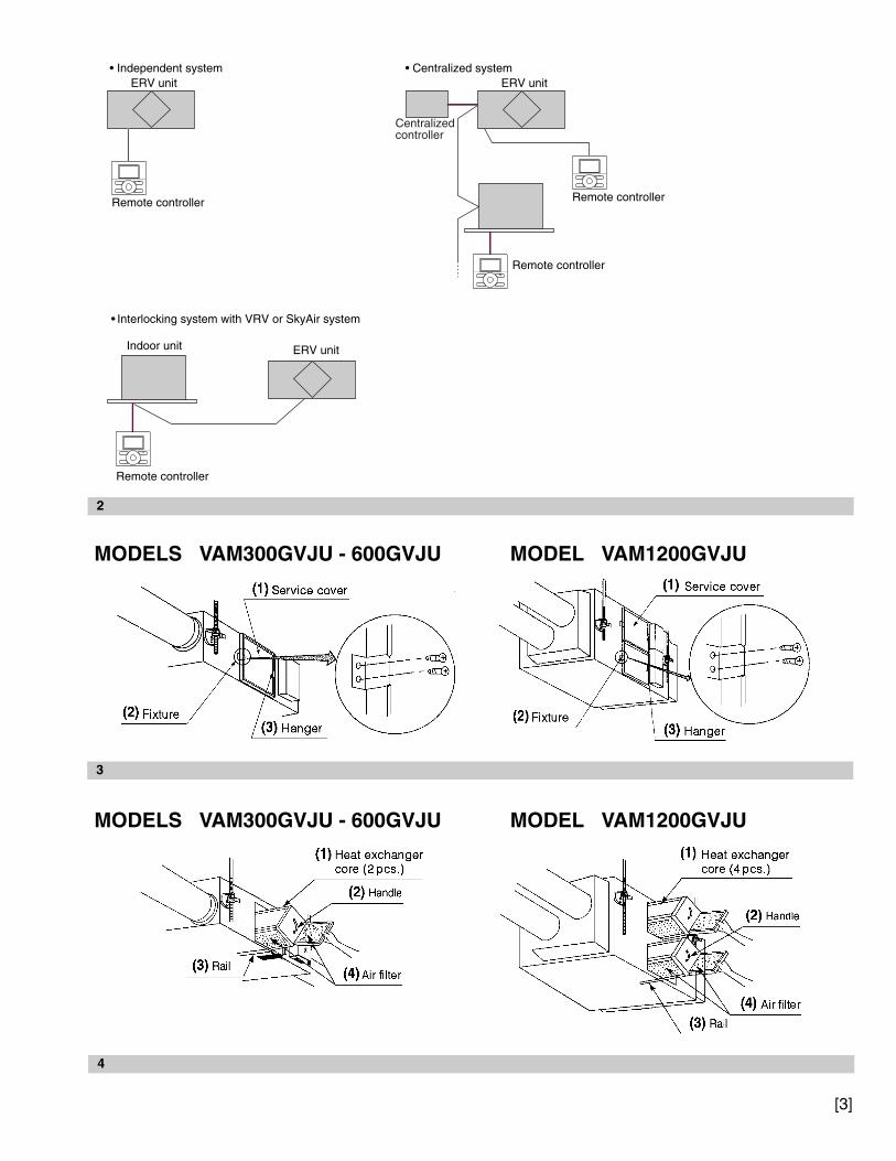
2-3 Explanation for SYSTEMSThis unit can be made a part of two different systems: as part of an interlocking system together with VRV or SkyAir system and as the independent system using only the ERV unit. The remote controller is required when using the unit as the independent system.Ask your dealer what kind of system is set up before oper-ation.See the operation manuals for details on how to operate each remote controller.
OPERATION for EACH SYSTEM (Refer to figure 2)• Independent system
The ERV unit can be operated by the remote controller.
• Interlocking system with VRV or SkyAir systemBoth of the air conditioner and the ERV unit can be operated by the remote controller.In mild climates when only the ERV unit is used without the air conditioner, select “ventilation mode” with the operation mode selector button.
• Centralized systemWhen the remote controller is not connected with the ERV unit, the centralized controller controls it.
When the remote controller is connected with the ERV unit, operation can be done by the centralized controller or the remote controller.During the indication of centralized control “ ” appears on the display, the ON/OFF and timer operation may not be possi-ble with the remote controller.
Other operations can be performed using the remote controller.
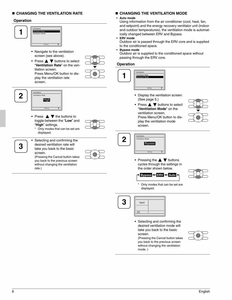
3. OPERATION PROCEDURE
3-1 INDEPENDENT AND INTERLOCKING OPERATION
VENTILATION SCREEN DISPLAY PROPERTIES
AUTOE ERV BYPASSRV
AIRPURIFY
CENTRALCONTROL
MASTERCONTROLLED
SETBACK
Operation
• Press Menu/OK button and display the main menu screen.
• Press buttons to select “Ventilation” on the main menu screen.Press Menu/OK button to dis-play the ventilation screen.
CENTRALCONTROL
1Setting
Main Menu
Air Flow DirectionVentilationScheduleOff TimerCelsius / FahrenheitMaintenance Information
1/2
Setting
Ventilation
Ventilation RateVentilation Mode
01_EN_3P034927-7M.fm Page 5 Thursday, June 16, 2011 9:59 AM
6 English
CHANGING THE VENTILATION RATE CHANGING THE VENTILATION MODE• Auto mode
Using information from the air conditioner (cool, heat, fan, and setpoint) and the energy recovery ventilator unit (indoor and outdoor temperatures), the ventilation mode is automat-ically changed between ERV and Bypass.
• ERV modeOutdoor air is passed through the ERV core and is supplied to the conditioned space.
• Bypass modeOutdoor air is supplied to the conditioned space without passing through the ERV core.
Operation
• Navigate to the ventilation screen (see above).
• Press buttons to select “Ventilation Rate” on the ven-tilation screen.Press Menu/OK button to dis-play the ventilation rate screen.
• Press the buttons to toggle between the “Low” and “High” settings.* Only modes that can be set are
displayed.
• Selecting and confirming the desired ventilation rate will take you back to the basic screen.(Pressing the Cancel button takes you back to the previous screen without changing the ventilation rate.)
1Setting
Ventilation
Ventilation RateVentilation Mode
2Setting
Ventilation Rate
Ventilation
High
3
Operation
• Display the ventilation screen. (See page 5.)
• Press buttons to select “Ventilation Mode” on the ventilation screen.Press Menu/OK button to dis-play the ventilation mode screen.
• Pressing the buttons cycles through the settings in the order shown below.
* Only modes that can be set are displayed.
• Selecting and confirming the desired ventilation mode will take you back to the basic screen.(Pressing the Cancel button takes you back to the previous screen without changing the ventilation mode. )
1Setting
Ventilation
Ventilation RateVentilation Mode
2Setting
Ventilation Mode
Ventilation
Bypass
Bypass ERV Auto
3 Vent
Return Setting
AUTOERV
01_EN_3P034927-7M.fm Page 6 Thursday, June 16, 2011 9:59 AM
English 7
NOTE
• Do not change operations suddenly.It can result not only in malfunction but also failure of switches or relays in the remote controller.
• Never press the button of the remote controller with a hard, pointed object.The remote controller may be damaged.
FRESH UP OPERATION• If the field setting for Fresh up operation is set to “Fresh up
air supply” : The volume of outdoor air supplied into the room is larger than that of exhaust air to outside. (This oper-ation prevents odor and moisture from kitchens and toilets from flowing into rooms.)
• If the field setting for Fresh up operation is set to “Fresh up air exhaust” :The volume of exhaust air to outs is larger than that of outdoor air supplied into the room. (This operation prevents hospital odor and floating bacteria from flowing out to corridors.)
DIRECT DUCT CONNECTION SYSTEMInstallation ExamplesDirect duct connection system
Independent duct system
The ERV unit cannot be operated independently when the air conditioner is connected to the ERV unit via a duct. When using the ERV unit, set the fan speed of air condi-tioner to “Low”.
3-2 SCHEDULE AND OFF TIMER For details of the following settings, refer to the operation man-ual attached to the remote controller.
SCHEDULEDaily Patterns• Day settings are selected from three patterns, i.e., “7Days”,
“Weekday/Weekend” and “Weekday/Sat/Sun”.
Settings• Set the startup time and operation stop time.
ON: Startup time, cooling and heating temperature set-points can be configured.
OFF: Operation stop time, cooling and heating setback tem-perature setpoints can be configured.( --: Indicates that the setback function is disabled for this time period. )
_: Indicates that the temperature setpoint and setback temperature setpoint for this time period is not speci-fied. The last active setpoint will be utilized.
• Up to five actions can be set for each day.
OFF TIMERSettings.• Possible to set in 10 minute increments from 30 to 180 min-
utes.
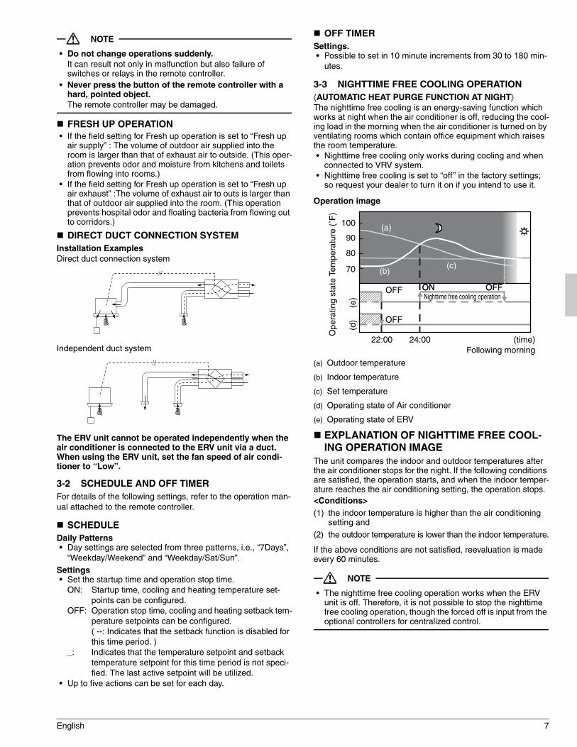
3-3 NIGHTTIME FREE COOLING OPERATION⟨AUTOMATIC HEAT PURGE FUNCTION AT NIGHT⟩The nighttime free cooling is an energy-saving function which works at night when the air conditioner is off, reducing the cool-ing load in the morning when the air conditioner is turned on by ventilating rooms which contain office equipment which raises the room temperature.• Nighttime free cooling only works during cooling and when
connected to VRV system.• Nighttime free cooling is set to “off” in the factory settings;
so request your dealer to turn it on if you intend to use it.
Operation image
(a) Outdoor temperature
(b) Indoor temperature
(c) Set temperature
(d) Operating state of Air conditioner
(e) Operating state of ERV
EXPLANATION OF NIGHTTIME FREE COOL-ING OPERATION IMAGE
The unit compares the indoor and outdoor temperatures after the air conditioner stops for the night. If the following conditions are satisfied, the operation starts, and when the indoor temper-ature reaches the air conditioning setting, the operation stops.<Conditions>(1) the indoor temperature is higher than the air conditioning
setting and
(2) the outdoor temperature is lower than the indoor temperature.
If the above conditions are not satisfied, reevaluation is made every 60 minutes.
NOTE
• The nighttime free cooling operation works when the ERV unit is off. Therefore, it is not possible to stop the nighttime free cooling operation, though the forced off is input from the optional controllers for centralized control.
OFF ONON
OFF
OFFOFF
100
90
80
70
(time)Following morning
22:00 24:00(d
)(e
)
Ope
ratin
g st
ate
Tem
pera
ture
(˚F
)
Nighttime free cooling operation
(a)
(b)(c)
01_EN_3P034927-7M.fm Page 7 Thursday, June 16, 2011 9:59 AM

8 English
4. MAINTENANCE(for a qualified service person only)
WARNING
• ONLY A QUALIFIED SERVICE PERSON IS ALLOWED TO PERFORM MAINTENANCE.
• BEFORE SERVICING TURN OFF ALL POWER SUPPLY.• To clean or do maintenance on the ERV, be sure to stop
operation and turn the power switch off. It may cause elec-tric shock or injury.
• Do not wash the ERV with water.Doing so may result in an electric shock.
CAUTION
• Use gloves when cleaning.Cleaning without gloves may cause injury.
• Watch your step.Use caution, as this requires working in high places.
• Do not use benzene or thinner to clean the outside surfaces of the unit.This may cause cracks, discoloration or machine trouble.
4-1 HOW TO CLEAN THE AIR FILTERClean the air filter when the display shows the message “Time to clean filter” at the bottom.It will display that it will operate for a set amount of time.
CLEANING FREQUENCYAT LEAST ONCE EVERY YEAR(FOR GENERAL OFFICE USE)(CLEAN THE FILTER MORE FREQUENTLY IF NECES-SARY.)• Increase the frequency of cleaning if the unit is installed in a
room where the air is extermely contaminated.• If the dirt becomes impossible to clean, change the air filter
(The replacement air filter is optional).1. Remove the service cover.
Go into ceiling through the inspection hatch, remove a fix-ture of service cover and take it off.(Refer to figure 3)
2. Remove the air filter.Take out from the heat exchanger cores. (Refer to figure 4)
3. Clean the air filter. (Refer to figure 5)Use a vacuum cleaner A) or wash the air filter with water B).A) Using a vacuum cleanerB) Washing with water
When the air filter is very dirty, use a soft brush and neutral detergent.
After cleaning, remove water and dry in the shade.
NOTE
• Do not wash the air filter with hot water of more than 122°F, as doing so may result in discoloration and/or deformation.
• Do not expose the air filter to fire, as doing so may result in burning.
• Do not use gasoline, thinner or other organic solvents.This may cause discoloration or deformation.
4. Fix the air filter.If the air filter is washed, remove water completely and allow to dry for 20 to 30 minutes in the shade. When dried completely, install the air filter back in place. (Refer to figure 6)
NOTE
• Be sure to install the air filter after servicing.(Missing air filter causes clogged heat exchanger core.)The air filter is an optional item and the replacement is avail-able.
5. Put the service cover back securely in place.Refer to the section (4-1, 1).
∗Consult your dealer if you want to change the time set-ting for when the filter sign goes on.
NOTE
• Do not remove the air filter except when cleaning.Breakdown may occur.
4-2 OPTIMUM OPERATIONObserve the following precautions to ensure the system oper-ates.• When the display shows one of the following messages
“Time to clean filter” “Time to clean filter & element” “Time to clean element”, ask a qualified service person to clean the filters (Refer to MAINTENANCE).
• Do not operate the ERV unit in Bypass mode when the indoor air is under heating in winter or when the out-door temperature is 86°F or higher.This may cause condensation to form on the unit, discharge grille or around air supply opening.
• Keep the unit and the remote controller at least 3.3 ft. away from televisions, radios, stereos and other similar equipments.This may cause distorted picture or noise.
• Turn off the main power supply switch when it is not used for long periods of time. When the main power switch is turned on, some watts of electricity is being used even if the system is not operating.
• Do not install the remote controller where the indoor temperature and humidity, respectively, are out of the range of 32-95°F and RH 40-80%.This may cause malfunction.
• Do not install the remote controller where direct sun-light may fall on it.This may cause discoloration or deformation.
To reset the filter indicator on the remote controller, press Menu/OK button and select “Reset Filter Indi-cater” on the main menu screen.
01_EN_3P034927-7M.fm Page 8 Thursday, June 16, 2011 9:59 AM

English 9
4-3 HOW TO CLEAN THE HEAT EXCHANGER CORE
CLEANING FREQUENCYAT LEAST ONCE EVERY TWO YEARS(FOR GENERAL OFFICE USE)(CLEAN THE CORE MORE FREQUENTLY IF NECESSARY.)
WARNING
• Replace the heat exchanger core if you find that the knob of the heat exchanger core is damaged or is dete-riorated when cleaning.There is falling danger.
1. Remove the service cover.Refer to the section (4-1, 1).
2. Remove the air filter.Refer to the section (4-1, 2).
3. Take out the heat exchanger cores.Pull out the air filter and then pull out the two heat exchanger cores. (Refer to figure 4)
4. Use a vacuum cleaner to remove dust and foreign objects on the surface of the heat exchanger core.(Refer to figure 7)• Use the vacuum cleaner equipped with a brush on the
tip of the suction nozzle.• Lightly contact the brush on the surface of the heat
exchanger core when cleaning.(Do not crush the heat exchanger core while clean-ing.)
CAUTION (During Operation)• Do not clean touching strongly with a vacuum cleaner. This
may crush the mesh of the heat exchanger core.• Never wash the heat exchanger core with water.• Have your dealer professionally clean the filter if it is very
dirty.
5. Put the heat exchanger core on the rail and insert it securely in place.
6. Install the air filter securely in place.(Refer to the section (4-1, 4))
7. Install the service cover securely in place.(Refer to the section (4-1, 5))
CAUTION
• Always use the air filter.If the air filter is not used, the heat exchanger core will be clogged, possibly causing poor performance and subse-quent failure.
4-4 INSPECTION OF THE FAN MOTER
NOTE
• When the fan motor fails, the remote controller does not dis-play any error code.Usage under that status will lead to insufficient ventilation.The air supply and exhaust fans should be checked once every one or two months.You can make a simple check such as below way.To check the airflow, hold a bar of which the end has a string or other similar lightweight item over the supply grille and exhaust grille.
5. TROUBLE SHOOTING
5-1 THE FOLLOWING SITUATIONS ARE NOT MALFUNCTIONS
• The unit does not start running.<Symptom>
The icon “ ” is displayed on the remote controller and pressing the on/off button causes the display to blink for a few seconds.
<Cause>This indicates that the centralized device controls the unit.The blinking display indicates that the remote controller can-not be used.
<Symptom>The fans start running after 1 minutes when pressing On/Off button.
<Cause>This indicates that the operation is in preparation.Wait for about 1 minute.
• The unit stops sometimes.<Symptom>
“U5” is displayed on the remote controller and the operation stops but then restarts after a few minutes.
<Cause>This indicates that the remote controller is intercepting noise from electrical appliances other than the ERV unit, and this prevents communication between the units, causing them to stop.Operation automatically restarts when the noise goes away.
5-2 IF ONE OF THE FOLLOWING MALFUNCTIONS OCCURS, TAKE THE MEASURES SHOWN BELOW AND CONTACT YOUR DAIKIN DEALER
The system must be repaired by a qualified service person.DO NOT CHECK AND REPAIR OPENING INSIDE THE UNIT BY YOURSELF.
WARNING
When the ERV is in abnormal conditions (smell of something burning, etc), cut off the power, and contact your dealer.Continued operation under such circumstances may result in a failure, electric shock and fire.
• The unit does not operate at all.a. Check if there is a power failure.
Measure: After power has been restored, start opera-tion again.
b. Check if the fuse has blown.Measure: Turn the power off and contact your dealer.
c. Check if breaker has worked.Measure:Turn the power on with the breaker switch in the off position.Do not turn the power on with the breaker switch in the trip position.(Contact your dealer.)
CENTRALCONTROL
Breaker (ground fault circuit interrupter)
ON
OFF
Switch
Trip position
01_EN_3P034927-7M.fm Page 9 Thursday, June 16, 2011 9:59 AM

10 English
• If a safety device such as a fuse, a breaker or a ground fault circuit interrupter frequency actuates, or ON/OFF switch does not properly work.Measure: Do not turn the power on.
• The remote controller buttons do not work well.Measure: Turn off the main power switch.
Error Code Display
• There are other malfunctions.Measure: Stop the unit.
List of error codes of Remote controller of the ERV-system
In case of the malfunction with the code in white letters on the black background in the unit still operates.However, be sure to have it inspected and repaired as soon as possible.If other than the above error codes are displayed, there is a possibility that the problem in question has occurred with an interlocked air conditioner or outdoor unit. See the operation manuals included with the air conditioners or outdoor units for details.
5-3 IF THE SYSTEM DOES NOT PROPERLY OPERATE EXCEPT FOR THE ABOVE MENTIONED CASE, AND NONE OF THE ABOVE MENTIONED MALFUNCTIONS IS EVIDENT, CONTACT YOUR DEALER, AND REQUEST FOR INVESTIGATION THE SYSTEM ACCORDING TO THE FOLLOWING PROCEDURES BY A QUALIFIED SERVICE PERSON
The following malfunctions must be checked by a qualified service person. Do not check by yourself.• The unit does not operate at all.
a. Check if there is a power failure.After power has been restored, start operation again.
b. Check if the fuse has blown.Change the fuse.
c. Check if breaker has worked.Contact your dealer.
d. Are there any problems with the power or wiring?Inspect the power and wiring.
e. Are there any problems with the fan unit?Inspect the fan motor and fan.
• Amount of discharge air is small and the discharging sound is high.a. Check if the air filter and heat exchanger core are clogged.
(Check both SA and RA air filter. Check both sides of cores.)Clean the air filter and heat exchanger core.
• Amount of discharge air is large and so is the sound.a. Check if the air filter and heat exchanger core are not
installed.Install the air filter and heat exchanger core.
6. AFTER-SALES SERVICE
WARNING
• Do not modify the unit.This may cause electric shock or fire.
• Do not disassemble or repair the unit.This may cause electric shock or fire.Contact your dealer.
• Do not remove or reinstall the unit by yourself.Incomplete installation may cause a water leakage, electric shock and fire.Contact your dealer.
When asking your dealer to repair, inform related staff of the details as follows:• Shipping date and installation date:• Malfunction:
Inform the staff of the defective details. (Error code being displayed on the remote controller.)
• Name, address, telephone number
Repair where the warranty term is expiredContact your dealer. If necessary to repair, pay service is available.
Minimum storage period of important partsEven after a certain type of the ERV unit is discontinued, we have the related important parts in stock for 6 years at least.The important parts indicate ones essential to operate the ERV unit.
Operation
• If an error occurs, either one of the following items will flash in the basic screen.
“Error: Push Menu button”* The operation lamp will flash.
“Warning: Push Menu button”* The operation lamp will not flash.
• Press Menu/OK button.
• The error code will flash and the service contact and model name or code may appear.
• Notify your Daikin dealer of the Error code and model name or code.
Errorcode
Description
64 Indoor air thermistor malfunction
65 Outdoor air thermistor malfunction
6A Dumper-related malfunction
6A Dumper-related malfunction + thermistor malfunction
U5 Transmission error between the unit and remote controller
U5 Setting error of remote controller
U8Transmission error between main remote controller and sub remote controller
UA Incorrect combination with indoor unit and remote controller.
UC Central control address over lapping
UE Transmission error between the unit and centralized controller
1 Cool Set to Cool 74F
Error : Press Menu button
Operation lamp
2Error code AI
Contact Info0123-456-7890
Indoor Model ---/000Outdoor Model ---/000
01_EN_3P034927-7M.fm Page 10 Thursday, June 16, 2011 9:59 AM

3P034927-7M EM09A029 (1107)
1645 Wallace Drive, Suite 110Carrollton, TX 75006
HT
00_CV_3P034927-7M.fm Page 7 Monday, June 20, 2011 1:25 PM