operation manual - daikin.it · 4 compressor 13 condenser 23 pump 5 suction stop valve (optional)...
TRANSCRIPT

OPERATION MANUAL
EWAQ080DAYNEWAQ100DAYNEWAQ130DAYNEWAQ150DAYNEWAQ180DAYNEWAQ210DAYNEWAQ240DAYNEWAQ260DAYN
Packaged air-cooled water chillers

CONTENTS Page
Introduction ....................................................................................... 1Technical specifications ............................................................................. 1Electrical specifications ............................................................................. 2Important information regarding the refrigerant used ................................ 3
Description ........................................................................................ 3Function of the main components.............................................................. 4Safety devices............................................................................................ 5Internal wiring - Parts table........................................................................ 6
Before operation................................................................................ 7Checks before initial start-up ..................................................................... 7Water supply.............................................................................................. 7Power supply connection and crankcase heating...................................... 7General recommendations ........................................................................ 7
Operation .......................................................................................... 8Digital controller ......................................................................................... 8Working with the unit ................................................................................. 8Advanced features of the digital controller............................................... 11
Troubleshooting ............................................................................... 19
Maintenance.................................................................................... 22Maintenance activities ............................................................................. 22Disposal requirements ............................................................................. 23
INTRODUCTION
This operation manual concerns packaged air-cooled water chillersof the Daikin EWAQ-DAYN series. These units are provided foroutdoor installation and used for cooling applications. The EWAQunits can be combined with Daikin fan coil units or air handling unitsfor air conditioning purposes. They can also be used for supplyingwater for process cooling.
This manual has been prepared to ensure adequate operation andmaintenance of the unit. It will tell you how to use the unit properlyand will provide help if problems occur. The unit is equipped withsafety devices, but they will not necessarily prevent all problemscaused by improper operation or inadequate maintenance.
In case of persisting problems contact your local Daikin dealer.
Technical specifications (1)
EWAQ080DAYN EWAQ180DAYNEWAQ100DAYN EWAQ210DAYNEWAQ130DAYN EWAQ240DAYNEWAQ150DAYN EWAQ260DAYN
Packaged air-cooled water chillers Operation manual
READ THIS MANUAL ATTENTIVELY BEFORE STARTINGUP THE UNIT. DO NOT THROW IT AWAY. KEEP IT INYOUR FILES FOR FUTURE REFERENCE.
Before starting up the unit for the first time, make sure thatit has been properly installed. It is therefore necessary tocarefully read the installation manual supplied with the unitand the recommendations listed in "Checks before initialstart-up" on page 7.
(1) Refer to the engineering data book for the complete list of specifications.
General EWAQ 080 100 130Dimensions HxWxD (mm) 2311x2000x2631Weight• machine weight (kg) 1350 1400 1500• operation weight (kg) 1365 1415 1517
Connections• chilled water inlet and outlet 3" OD 3" OD 3" OD• evaporator drain 1/2"G 1/2"G 1/2"G
Internal water volume (l) 15 15 17Expansion vessel (only for OPSP, OPTP and OPHP)• volume (l) 35 35 35• pre-pressure (bar) 1.5 1.5 1.5
Safety valve water circuit
(bar)3.0 3.0 3.0
Pump (only for OPSP)• type Vertical in-line pump• model (standard) TP 50-240/2 TP 50-240/2 TP 65-230/2
CompressorType semi-hermetic scroll compressorQty x model 2x SJ180-4 2x SJ240-4 4x SJ161-4Speed (rpm) 2900 2900 2900Oil type FVC68D FVC68D FVC68DOil charge volume (l) 2x 6.2 2x 6.2 4x 3.3CondenserNominal air flow (m3/min) 780 780 800No. of motors x output (W) 4x 500 4x 500 4x 600EvaporatorModel P120T P120T DV47
General EWAQ 150 180 210Dimensions HxWxD (mm) 2311x2000x2631 2311x2000x3081Weight• machine weight (kg) 1550 1800 1850• operation weight (kg) 1569 1825 1877
Connections• chilled water inlet and outlet 3" OD 3" OD 3" OD• evaporator drain 1/2"G 1/2"G 1/2"G
Internal water volume (l) 19 25 27Expansion vessel (only for OPSP, OPTP and OPHP)• volume (l) 35 35 35• pre-pressure (bar) 1.5 1.5 1.5
Safety valve water circuit
(bar)3.0 3.0 3.0
Pump (only for OPSP)• type Vertical in-line pump• model (standard) TP 65-230/2 TP 65-260/2 TP 65-260/2
CompressorType semi-hermetic scroll compressor
Qty x model 4x SJ180-4 2x SJ180-4 + 2x SJ240-4 4x SJ240-4
Speed (rpm) 2900 2900 2900Oil type FVC68D FVC68D FVC68DOil charge volume (l) 2x 6.2 2x 6.2 + 2x 6.2 4x 6.2CondenserNominal air flow (m3/min) 860 1290 1290No. of motors x output (W) 4x 1000 6x 1000 6x 1000EvaporatorModel DV47 DV58 DV58
Operation manual
1EWAQ080~260DAYN
Packaged air-cooled water chillers4PW35556-1E

Electrical specifications (1)
General EWAQ 240 260Dimensions HxWxD (mm) 2311x2000x4833Weight• machine weight (kg) 3150 3250• operation weight (kg) 3189 3292
Connections• chilled water inlet and outlet 3" 3"• evaporator drain 1/2"G 1/2"G
Internal water volume (l) 39 42Expansion vessel (only for OPSP, OPTP and OPHP)• volume (l) 50 50• pre-pressure (bar) 1.5 1.5
Safety valve water circuit
(bar)3.0 3.0
Pump (only for OPSP)• type Vertical in-line pump• model (standard) TP 65-260/2 TP 65-260/2
Compressor
Type semi-hermetic scroll compressor
Qty x model 2x SJ240-4 + 2x SJ300-4 4x SJ300-4
Speed (rpm) 2900 2900Oil type FVC68D FVC68D
Oil charge volume(l) 2x 6.2 +
2x 6.2 4x 6.2
CondenserNominal air flow (m3/min) 1600 1600No. of motors x output (W) 8x 600 8x 600EvaporatorModel DV58 DV58
EWAQ 080 100 130 150Power supply YN• Phase 3~• Frequency (Hz) 50• Voltage (V) 400• Voltage tolerance (%) ±10
Unit• Nominal running current (A) 60 72 88 113• Maximum running current (A) 96 120 160 177• Recommended fuses
according to IEC 269-2(A)
3x 125 gL 3x 160 gL 3x 200 gL 3x 200 gL
Compressor• Circuit 1
Circuit 2
(hp)(hp)
15 + 15—
20 + 20—
13 + 1313 + 13
15 + 1515 + 15
• Phase 3~• Frequency (Hz) 50• Voltage (V) 400• Nominal running current
Circuit 1Circuit 2
(A)(A)
39 + 39—
51 + 51—
35 + 3535 + 35
39 + 3939 + 39
Control and fan motor• Phase 1~• Frequency (Hz) 50• Voltage (V) 230 V• Maximum running current (A) 4x 1.5 4x 1.5 4x 1.6 4x 2.3
Pump• Power (kW) 2.2 2.2 3 3• Nominal running current (A) 4.5 4.5 6.3 6.3
Heater tape (OP10)• Supply voltage (V) 230 V ±10%• Power (standard)
(OPSP)
(OPBT)
1x 300 W2x 300 W
2x 300 W + 150 W• Optional field heater maximum 1 kW• Recommended fuses (A) 2x 10
EWAQ 180 210 240 260Power supply YN• Phase 3~• Frequency (Hz) 50• Voltage (V) 400• Voltage tolerance (%) ±10
Unit• Nominal running current (A) 131 144 162 181• Maximum running current (A) 209 233 262 290• Recommended fuses
according to IEC 269-2(A)
3x 250 gL 3x 250 gL 3x 300 gL 3x 355 gL
Compressor• Circuit 1
Circuit 2
(hp)(hp)
20 + 1520 + 15
20 + 2020 + 20
25 + 2025 + 20
25 + 2525 + 25
• Phase 3~• Frequency (Hz) 50• Voltage (V) 400• Nominal running current
Circuit 1Circuit 2
(A)(A)
51 + 3951 + 39
51 + 5151 + 51
65 + 5165 + 51
65 + 6565 + 65
Control and fan motor• Phase 1~• Frequency (Hz) 50• Voltage (V) 230 V• Maximum running current (A) 6x 2.3 6x 2.3 8x 1.6 8x 1.6
Pump• Power (kW) 4 4 4 4• Nominal running current (A) 8.0 8.0 8.0 8.0
Heater tape (OP10)• Supply voltage (V) 230 V ±10%• Power (standard)
(OPSP)
(OPBT)
1x 300 W2x 300 W
2x 300 W + 150 W• Optional field heater maximum 1 kW• Recommended fuses (A) 2x 10
EWAQ080~260DAYNPackaged air-cooled water chillers4PW35556-1E
Operation manual
2

Important information regarding the refrigerant used
This product contains fluorinated greenhouse gases covered by the Kyoto Protocol.
Refrigerant type: R410AGWP(1) value: 1975
(1) GWP = global warming potential
Periodical inspections for refrigerant leaks may be required depending on European or local legislation. Please contact your local dealer for moreinformation.
DESCRIPTION
The EWAQ air-cooled water chillers are available in 8 standard sizes.
Figure - Main components
1200
1200
10001000
3000
EWAQ240+260
31
1200
1200
1000
16195
1000
32922
16
26
5
26
27
23
321 21 10 93834
3000
3939 39 39202 23 22321417 1718
28 152425 7 24447
6
27
25
32 33 12
37
11
3530
81336
1200
1200
10001000
3000
EWAQ080~150 EWAQ180+210
1 Evaporator 14 Ambient temperature sensor (R1T) 29 Pump (optional)
2 Condenser 15 Drier + charge valve 30 Buffertank (optional)
3 Compressor 16 Power supply intake 31 Expansion vessel (optional)
4 Electronic expansion valve + sight glass with moisture indication
17 Switchbox 32 Waterfilter
18 Digital display controller (behind service panel)
33 Water stop valve (optional)
5 Discharge stop valve (optional) 34 Frame
6 Suction stop valve (optional) 19 Field wiring intake 35 Buffertank drain valve
7 Liquid stop valve (optional) 20 Main isolator switch 36 Regulating valve (optional)
8 Chilled water in (Victaulic® coupling) 21 Transportbeam 37 Water safety valve (optional)
9 Chilled water out (Victaulic® coupling) 22 Flowswitch 38 Pressure gauge (optional)
10 Water drain evaporator 23 Fan 39 Eyebolt (for lifting the unit) (only for EWAQ080~210)
11 Air purge 24 Safety valve
12 Leaving water temperature sensor (R3T)
25 High pressure sensor
26 Low pressure sensor
13 Entering water temperature sensor (R2T)
27 High pressure switch Required space around the unit for service and air intake
28 Oil sight glass
Operation manual
3EWAQ080~260DAYN
Packaged air-cooled water chillers4PW35556-1E

Function of the main components
Figure - Functional diagram
As the refrigerant circulates through the unit, changes in its state orcondition occur. These changes are caused by the following maincomponents:
■ CompressorThe compressor (M*C) acts as a pump and circulates the refri-gerant in the refrigeration circuit. It compresses the refrigerantvapour coming from the evaporator at the pressure at which itcan easily be liquefied in the condenser.
■ CondenserThe function of the condenser is to change the state of therefrigerant from gaseous to liquid. The heat gained by the gas inthe evaporator is discharged through the condenser to theambient air, and the vapour condenses to liquid.
■ Filter/drierThe filter installed behind the condenser removes small particlesfrom the refrigerant to prevent damage to the compressor andexpansion valve.The drier takes the water out of the system.
■ Expansion valveThe liquid refrigerant coming from the condenser enters theevaporator via an expansion valve. The expansion valve bringsthe liquid refrigerant to a pressure at which it can easily beevaporated in the evaporator.
p <
p >
p >
(*)
M12CM11C p <
p >
p >
M22C M21C
M15F
M13F
M14F
M25F
M23F
M24F
B1PH B2PH
S2PHS1PH
R17T R37TR14T R34T
B1PL B2PL
R15T R25T R35T R45T
Y11E Y21E
PHE
t >
2
44
1010
4 4
(*)
14
9 9
5 5
11
12 12
8 8
11
16
18
16
18
17 17
15 15
13 13
6 6
C
D
CDD
D
1010
12 12
12 12
12 12
12 12
12 12
A
7
B
7
1 3
D D D
19
22
21
20 24 27
2628
28
25
2329
2132
3130
t > t >R3T R2T
20
20
D D
1 Water outlet 11 Electronic expansion valve + sight glass with moisture indication
20 Service port 30 Filter
2 Evaporator 21 Drain valve 31 Shut off valve
3 Water inlet 12 Check valve 22 Regulating valve 32 Water circuit safety valve
4 Compressor 13 Condenser 23 Pump
5 Suction stop valve (optional) 14 Ambient temperature sensor 24 Fill port (*) Standard (A) or dual pressure relief valve (B)
6 Discharge stop valve (optional) 15 Fan 25 Drain port
7 Refrigerant circuit safety valve 16 High pressure sensor 26 Expansion vessel A Standard
8 Drier/charge valve 17 Low pressure sensor 27 Pressure gauge B Dual pressure relief valve
9 Liquid stop valve (optional) 18 High pressure switch 28 Air purge C Only for 70~80 HP units
10 Oil sight glass 19 Flowswitch 29 Buffer tank D Optional
EWAQ080~260DAYNPackaged air-cooled water chillers4PW35556-1E
Operation manual
4

■ EvaporatorThe main function of the evaporator is to take heat from thewater that flows through it. This is done by turning the liquidrefrigerant, coming from the condenser, into gaseousrefrigerant.
■ Water in/outlet connectionThe water inlet and outlet connection allow an easy connectionof the unit to the water circuit of the air handling unit or industrialequipment.
Safety devices
The unit is equipped with three kinds of safety device:
1 General safety devices
General safety devices shut down all circuits and stop the wholeunit. For this reason the unit has to be manually put on againafter a general safety occurred.
2 Circuit safety devices
Circuit safety devices shut down the circuit they protect, whilethe other circuits remain activated.
3 Part safety devices
Part safety devices shut down the part they protect.
An overview of all safety devices is given below.
■ Overcurrent relays
■ Overcurrent relay for compressors (only for SJ161-4) (circuitsafety device)The overcurrent relay protects the compressor motor in case ofoverload, phase failure or too low voltage.
■ Overcurrent relay for fans (part safety device)The overcurrent relay protects the fan motors in case of overload,phase failure or too low voltage.
■ Overcurrent relay for pump (general safety device)The overcurrent relay protects the pump in case of overload,phase failure or too low voltage.
When activated, the overcurrent relays have to be reset in theswitch box and the controller needs to be reset manually.
■ Compressor SJ161-4 thermal protector (part safety devices)Compressor SJ161-4 is equipped with an internal overloadmotor protection to protect the unit against excessive currentand temperature caused by overloading, low refrigerant flow orphase loss. The compressor will shut down and willautomatically restart when temperature returns to normal. Thisis not detected by the controller.
■ Compressor SJ180-4 electronic protection module (circuit safetydevice)Compressor SJ180-4 is equipped with an electronic protectionmodule to provide for efficient and reliable protection againstoverheating, overloading, and phase loss. The controller willdetect the shut down of the compressor. The controller needs tobe reset manually. The compressor is internally protectedagainst reverse phase.
■ Compressors SJ240-4 and SJ300-4 electronic protectionmodules (circuit safety device)Compressors SJ240-4 and SJ300-4 are equipped with anelectronic protection module to provide for efficient and reliableprotection against overheating, overloading, phase loss andphase reversal. The controller will detect the shut down of thecompressor. The controller needs to be reset manually.
■ Reverse phase protector (general safety device)The reverse phase protectors prevent the unit from beingoperated in reverse phase. If the unit does not start, two phasesof the power supply must be inverted.
■ Flowswitch (general safety devices)The unit is protected by a flowswitch (S1L).When the water flow becomes lower than the minimum allowedwater flow, the flowswitch shuts down the unit. When the waterflow becomes normal, the protection resets automatically but thecontroller still needs to be reset manually.
■ Discharge thermal protectors (circuit safety devices)The unit is equipped with discharge thermal protectors (R*T).The protectors are activated when the temperature of therefrigerant leaving the compressor becomes too high. When thetemperature returns to normal the controller needs to be resetmanually.
■ Freeze-up protection (general safety devices)The freeze-up protection prevents the water in the evaporatorfrom freezing during operation.
■ When the outlet water temperature is too low, the controllershuts down the compressors. When the outlet watertemperature returns to normal, the controller resetsautomatically.
■ When the refrigerant temperature is too low, the controllershuts down the unit. When the refrigerant temperaturereturns to normal, the controller needs to be reset manually.
■ Low pressure safety (circuit safety devices)When the suction pressure of a circuit is too low, the circuitcontroller shuts down the circuit. When the pressure returns tonormal, the safety device can be reset on the controller.
■ Pressure relief safety valve (general safety devices)The safety valve is activated when the pressure in the refrigerantcircuit becomes too high. If this occurs, shut down the unit andcontact your local dealer.
■ High pressure setback (circuit safety device)The high pressure setback prevents the high pressure tobecome too high so that high pressure switch is activated.When the high pressure is too high, the controller shuts downthe compressor. When the pressure returns to normal, thecontroller resets automatically.
■ High pressure switch (circuit safety devices)Each circuit is protected by a high pressure switch (S*PH) whichmeasures the condenser pressure (pressure at the outlet of thecompressor).When the pressure becomes too high, the pressure switch isactivated and the circuit stops.When the pressure becomes normal again, the protection resetsautomatically but the controller still needs to be reset manually.The switch is factory-set and may not be adjusted.
The overcurrent relays are factory set and may not beadjusted.
Operation manual
5EWAQ080~260DAYN
Packaged air-cooled water chillers4PW35556-1E

Internal wiring - Parts table
Refer to the internal wiring diagram supplied with the unit. Theabbreviations used are listed below:
A01P...................... PCB extension
A02P.............**...... PCB communication (only for option EKACPG)
A4P........................ PCB wired remote controller
A5P...............**...... PCB wired remote controller (only for option EKRUPG)
A11P,A21P............. PCB main controller circuit 1, circuit 2
A13P,A23P....**...... Frequency inverter circuit 1, circuit 2 (only for option OPIF)
A71P...................... PCB EEV driver
B1PH,B2PH........... High pressure sensor circuit 1, circuit 2
B1PL,B2PL ............ Low pressure sensor circuit 1, circuit 2
DS1........................ PCB DIP-switch
E1HS ............## .... Switch box heater with fan (only for EWAQ130~260 with option OPIF)
E3H...............**...... Heater tape (only for option OP10)
E4H...............**...... Heater tape (only for options OP10, OPSP, OPHP and OPTP)
E5H...............* ....... Fieldheater
E6H...............**...... Buffertank heater (only for option OP10 and OPBT)
E7H...............## .... Switch box heater(only for EWAQ080+100 with option OPIF)
E11HC,E12HC ...... Crankcase heater compressor circuit 1
E21HC,E22HC ...... Crankcase heater compressor circuit 2 (only for EWAQ130~260)
F1~F3 ...........# ...... Main fuses
F1U........................ Fuse PCB
F4,F5 ............# ...... Fuse for heater
F6B ........................ Autofuse for primary of TR1
F8B ...............**...... Autofuse for switchbox heater (only for option OPIF)
F9B ........................ Autofuse for secondary of TR1
F11B,F12B ............ Autofuse for compressors (M11C, M12C) (only for EWAQ130~260)
F14B,F24B ............ Autofuse for fanmotors circuit 1, circuit 2
F15B,F25B ...**...... Autofuse for fanmotors circuit 1, circuit 2 (only for option OPIF)
F16B .............## .... Autofuse for pump (K1P) (only for options OPSP, OPHP, OPTC, OPTP and OPSC)
F17B .............## .... Autofuse for pump (K2P) (only for options OPTC and OPTP)
F21B,F22B ............ Autofuse for compressors (M21C, M22C) (only for EWAQ130~260)
H1P~H6P .....* ....... Indication lamp for changeable digital outputs
H11P,H12P ............ Indication lamp for operation compressor circuit 1 C11M, C12M
H21P,H22P ............ Indication lamp for operation compressor circuit 2 C21M, C22M (only for EWAQ130~260)
HAP~HEP.............. LED PCB
K1A,K2A ................ Auxiliary relay for compressor safety circuit 1, circuit 2
K1P...............## .... Pump contactor (only for options OPSP, OPHP, OPTC, OPTP and OPSC)
K1R~K22R ............ PCB relay
K1S...............* ....... Overcurrent relay pump
K2P...............## .... Pump contactor (only for options OPTC and OPTP)
K3A........................ Auxiliary relay for heater tape
K11M,K12M........... Compressor contactor for circuit 1
K13F,K14F............. Fancontactor for circuit 1
K13S,K14S ............ Fan overcurrent relay for circuit 1
K15F ...................... Fancontactor for circuit 1 (only for EWAQ080+100 and EWAQ180~260)
K15S ......................Fan overcurrent relay for circuit 1 (only for EWAQ080+100 and EWAQ180~260)
K16F ......................Fancontactor for circuit 1 (only for EWAQ080+100 and EWAQ240+260)
K16S ......................Fan overcurrent relay for circuit 1 (only for EWAQ080+100 and EWAQ240+260)
K21M,K22M ...........Compressor contactor for circuit 2 (only for EWAQ130~260)
K23F,K24F .............Fancontactor for circuit 2 (only for EWAQ130~260)
K23S,K24S ............Fan overcurrent relay for circuit 2(only for EWAQ130~260)
K25F ......................Fancontactor for circuit 2 (only for EWAQ180~260)
K25S ......................Fan overcurrent relay for circuit 2 (only for EWAQ180~260)
K26F ......................Fancontactor for circuit 2 (only for EWAQ240+260)
K26S ......................Fan overcurrent relay for circuit 2 (only for EWAQ240+260)
M1P.............. * .......Pump motor 1 (only for options OPSP, OPHP, OPTC and OPTP)
M2P.............. * .......Pump motor 2(only for options OPTC and OPTP)
M11C,M12C...........Compressor motors circuit 1
M13F,M14F ............Fan motors circuit 1
M15F......................Fan motors circuit 1 (only for EWAQ080+100 and EWAQ180~260)
M16F......................Fan motors circuit 1 (only for EWAQ080+100 and EWAQ240+260)
M21C,M22C...........Compressor motors circuit 2 (only for EWAQ130~260)
M23F,M24F ............Fan motors circuit 2 (only for EWAQ130~260)
M25F......................Fan motor circuit 2 (only for EWAQ180~260)
M26F......................Fan motor circuit 2 (only for EWAQ240+260)
PE ..........................Main earth terminal
Q1T.............. ** ......Thermostat (only for option OP10)
Q11C,Q12C ...........Thermal protector compressor circuit 1 (only for EWAQ130)
Q11C,Q12C ...........Electronic protection module compressor circuit 1 (not for EWAQ130)
Q21C,Q22C ...........Thermal protector compressor circuit 2 (only for EWAQ130)
Q21C,Q22C ...........Electronic protection module compressor circuit 2 (only for EWAQ150~260)
R1T ........................Ambient temperature sensor
R2T ........................ Inlet water temperature sensor
R3T ........................Outlet water temperature sensor
R8T .............. * .......Temperature sensor for changeable analogue input
R14T ......................Suction temperature sensor circuit 1
R15T,R25T.............Discharge temperature sensor circuit 1
R17T ......................Refrigerant piping temperature sensor circuit 1
R34T ......................Suction temperature sensor circuit 2 (only for EWAQ130~260)
R35T,R45T.............Discharge temperature sensor circuit 2 (only for EWAQ130~260)
R37T ......................Refrigerant piping temperature sensor circuit 2 (only for EWAQ130~260)
S1A~S3A ...............PCB DIP-switch
S1L.........................Flowswitch
S1M........................Main isolator switch
S1PH,S2PH ...........High pressure switch circuit 1, circuit 2
S1S~S5S ..... * .......Switch for changeable digital input
S1T .............. ##.....Thermal contact (only for option OPIF)
S2M.............. #.......Heater tape isolator switch
T1A .............. ** ......Current transducer (only for option OP57)
EWAQ080~260DAYNPackaged air-cooled water chillers4PW35556-1E
Operation manual
6
T1V............... ** ......Voltage transducer (only for option OP57)
TR1 ........................Transfo control circuit (400 V/230 V)
TR1A ............ ** ......Current measurement transfo(only for option OP57)
V1C ........................Ferrite core
V1F,V2F........ ** ......Noise filter circuit 1, circuit 2 (only for EWAQ130~210 with option OPIF)
V2C .............. ** ......Ferrite core (only for option EKACPG)
X*A .........................PCB terminal
X*Y .........................Connector
X1M........................PCB terminal strip
Y11E ......................Electronic expansion valve cooling circuit 1
Y21E ......................Electronic expansion valve cooling circuit 2 (only for EWAQ130~260)
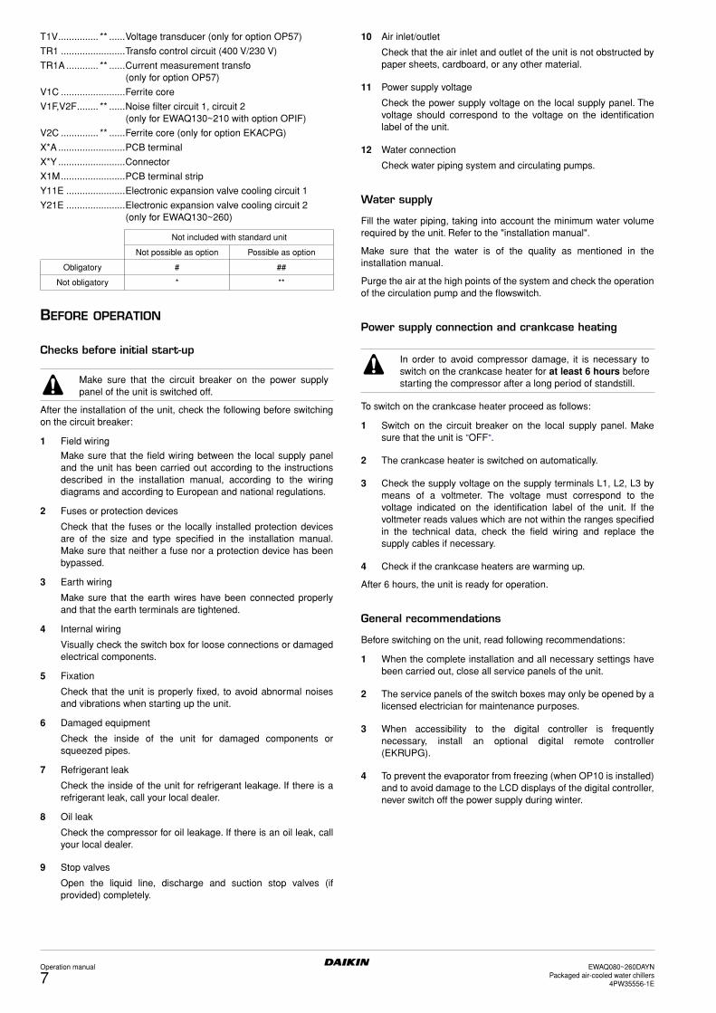
BEFORE OPERATION
Checks before initial start-up
After the installation of the unit, check the following before switchingon the circuit breaker:
1 Field wiring
Make sure that the field wiring between the local supply paneland the unit has been carried out according to the instructionsdescribed in the installation manual, according to the wiringdiagrams and according to European and national regulations.
2 Fuses or protection devices
Check that the fuses or the locally installed protection devicesare of the size and type specified in the installation manual.Make sure that neither a fuse nor a protection device has beenbypassed.
3 Earth wiring
Make sure that the earth wires have been connected properlyand that the earth terminals are tightened.
4 Internal wiring
Visually check the switch box for loose connections or damagedelectrical components.
5 Fixation
Check that the unit is properly fixed, to avoid abnormal noisesand vibrations when starting up the unit.
6 Damaged equipment
Check the inside of the unit for damaged components orsqueezed pipes.
7 Refrigerant leak
Check the inside of the unit for refrigerant leakage. If there is arefrigerant leak, call your local dealer.
8 Oil leak
Check the compressor for oil leakage. If there is an oil leak, callyour local dealer.
9 Stop valves
Open the liquid line, discharge and suction stop valves (ifprovided) completely.
10 Air inlet/outlet
Check that the air inlet and outlet of the unit is not obstructed bypaper sheets, cardboard, or any other material.
11 Power supply voltage
Check the power supply voltage on the local supply panel. Thevoltage should correspond to the voltage on the identificationlabel of the unit.
12 Water connection
Check water piping system and circulating pumps.
Water supply
Fill the water piping, taking into account the minimum water volumerequired by the unit. Refer to the "installation manual".
Make sure that the water is of the quality as mentioned in theinstallation manual.
Purge the air at the high points of the system and check the operationof the circulation pump and the flowswitch.
Power supply connection and crankcase heating
To switch on the crankcase heater proceed as follows:
1 Switch on the circuit breaker on the local supply panel. Makesure that the unit is "OFF".
2 The crankcase heater is switched on automatically.
3 Check the supply voltage on the supply terminals L1, L2, L3 bymeans of a voltmeter. The voltage must correspond to thevoltage indicated on the identification label of the unit. If thevoltmeter reads values which are not within the ranges specifiedin the technical data, check the field wiring and replace thesupply cables if necessary.
4 Check if the crankcase heaters are warming up.
After 6 hours, the unit is ready for operation.
General recommendations
Before switching on the unit, read following recommendations:
1 When the complete installation and all necessary settings havebeen carried out, close all service panels of the unit.
2 The service panels of the switch boxes may only be opened by alicensed electrician for maintenance purposes.
3 When accessibility to the digital controller is frequentlynecessary, install an optional digital remote controller(EKRUPG).
4 To prevent the evaporator from freezing (when OP10 is installed)and to avoid damage to the LCD displays of the digital controller,never switch off the power supply during winter.
Not included with standard unit
Not possible as option Possible as option
Obligatory # ##
Not obligatory * **
Make sure that the circuit breaker on the power supplypanel of the unit is switched off.
In order to avoid compressor damage, it is necessary toswitch on the crankcase heater for at least 6 hours beforestarting the compressor after a long period of standstill.
Operation manual
7EWAQ080~260DAYN
Packaged air-cooled water chillers4PW35556-1E

OPERATION
The EWAQ units are equipped with a digital controller (locatedbehind the service panel) offering a user-friendly way to set up, useand maintain the unit.
This part of the manual has a task-oriented, modular structure. Apartfrom the first section, which gives a brief description of the controlleritself, each section or subsection deals with a specific task you canperform with the unit.
Depending on the unit there are one or two cooling circuits in thesystem. The units EWAQ130~260 exist out of two circuits, whereasthe units EWAQ080+100 only have one circuit. These circuits aregenerally named C1 and C2 in the following descriptions. So allinformation about circuit 2 (C2) is not applicable for EWAQ080+100units.
Digital controller
User interface
The digital controller consists of an alphanumeric display, labelledkeys which you can press and a number of LEDs.
■ Digital controller and digital remote controller (EKRUPG)
Figure - Digital (remote) controller
How to enter a menu
Scroll through the main menu using the fi and Ì keys to go to themenu of your choice. Push the ‡ key to enter the selected menu.
■ Access to the setpoints menu (∑) and the usersettings menu(Å) is protected by a password, refer to "Changing the userpassword" on page 19.
■ The cool/heat menu is not available for EWAQ units.
Connection of a remote digital controller to the unit
For a remote digital controller a cable length of up to 500 metresbetween the remote digital controller and the unit is allowed. Thisgives the opportunity to control the unit from a considerable distance.Refer to "Cable for remote digital controller" in the installation manualfor cable specifications.
These restrictions are the same for units in a DICN configuration.
Working with the unit
This chapter deals with the everyday usage of the unit. Here, you willfind how to perform routine tasks, such as:
■ "Setting the language" on page 8
■ "Switching the unit on" on page 8
■ "Consulting actual operational information" on page 9
■ "Adjusting the temperature setpoint" on page 10
■ "Resetting the unit" on page 10
Setting the language
If desired, the operating language can be changed to any of thefollowing languages: English, German, French, Spanish or Italian.
1 Enter the Å usersettings menu. Refer to chapter "How to entera menu" on page 8.
2 Go to the Language submenu of the Å usersettings menu usingthe fi and Ì keys and press the ‡ key to enter.
3 Press ‡ to change the operating language until the desiredlanguage is active.
The controller is factory set to English.
Switching the unit on
1 Press the œ key on the controller.
Depending on whether or not a remote ON/OFF switch hasbeen configured (refer to the installation manual), the followingconditions may occur.When no remote ON/OFF switch is configured, the LED insidethe œ key lights up and an initialization cycle is started. Once allthe timers have reached zero, the unit starts up.When a remote ON/OFF switch is configured, the following tableapplies:
2 If the water chiller does not start after a few minutes, refer to"Troubleshooting" on page 19.
œ key, to start up or to shut down the unit.
π key, to enter the safeties menu or to reset an alarm.
ƒ key, to enter the main menu
fi
Ì
keys, to scroll up or down through the screens of a menu(only in case ^, v or ÷ appears) or to raise, respectivelylower a setting.
‡ key, to confirm a selection or a setting.
NOTE Temperature readout tolerance: ±1°C.
Legibility of the alphanumeric display may decrease indirect sunlight.
MenuNot selected Selected
Readout menuSetpoints menuUsersettings menuTimers menuHistory menuInfo menuI/O status menuLogin/logout menuNetwork menuCool/heat menu
==========
º
Ò
Â
µ
®
†
Ú
æ
∂
Ï
ª
∑
Å
Ó
‚
™
Ÿ
Æ
∆
Í
ªÒµ®
†Úæ∂Ï
NOTE When a remote digital controller is connected to astand-alone unit, the address of the remote digitalcontroller has to be set to SUB by means of the DIP-switches on the back of the remote digital controller.Refer to the installation manual "Setting the addresseson the remote digital controller" for setting the address.
NOTE If the password protection is set to ON, the correctpassword has to be given before any furtheraction is possible.
Local keyRemote
ON/OFF switch Unit œ LED
ON ON ON ON
ON OFF OFF Flashing
OFF ON OFF OFF
OFF OFF OFF OFF
EWAQ080~260DAYNPackaged air-cooled water chillers4PW35556-1E
Operation manual
8

Switching the unit off
If no remote on/off switch is configured:Press the œ key on the controller.The LED inside the œ key goes out.
If a remote on/off switch is configured:Press the œ key on the controller or switch the unit off using theremote on/off switch.The LED inside the œ key goes out in the first case and startsblinking in the second case.
Switching units ON/OFF in a DICN system
If the œ key is pressed on a unit with status NORMAL or STANDBY, allother units with status NORMAL or STANDBY will be ON or OFF.
If the œ key is pressed on a unit with status DISCONNECT ON/OFF,only this unit will be ON or OFF.
Consulting actual operational information
1 Enter the readout menu. Refer to the chapter "How to enter amenu" on page 8.
The controller automatically shows the first screen of thereadout menu which provides the following information:
• ¶ cooling mode
• § heating mode
• ≠ fan (H high or L low)
• ¡ low noise mode activated (only available when optionOPIF is installed)
• … pump on
• …1/2 in case of dual pump control: pump 1/2 on
• ∞11/12 circuit 1 compressor 1/2 on
• ∞21/22 circuit 2 compressor 1/2 on
• ≤ alarm and last occured malfunction code (0U4 inexample)
• 13$6¢ actual temperature (inlet or outlet temperaturedepending on active mode)
• 12$0¢ temperature setpoint (inlet or outlet temperaturedepending on active mode)
2 Press the Ì key to enter the next screen of the readout menu.
• MANUAL MODE or COOL INLSP1/2 or COOL OUTLSP1/2:manual/automatic control mode operation. If the automaticcontrol mode is selected, the controller will indicate the activetemperature setpoint. Depending on the status of the remotecontact, setpoint one or setpoint two is active.
• INL WATER: actual inlet water temperature.
• OUTL WATER: actual outlet water temperature.
• AMBIENT: actual ambient temperature.
3 Press the Ì key to enter the next screen of the readout menu.
The TEMPERATURE screen of the readout menu providesinformation concerning the discharge temperature of thecompressors (C11 and C12/C21 and C22).
4 Press the Ì key to enter the next screen of the readout menu.
The C1/C2 TEMP. READOUT screen of the readout menuprovides information concerning the refrigerant temperature(REFR) of circuit 1/circuit 2.
5 Press the Ì key to enter the next screen of the readout menu.
The ACT. PRESSURES screen of the readout menu providesinformation concerning the actual pressures of circuit.
■ HP1/2: high pressure of the refrigerant in circuit 1/2. The firstnumber stands for the pressure in bar, the second numberstands for the bubble point saturation temperature in degreesCelsius.
■ LP1/2: low pressure of the refrigerant in circuit 1/2. The firstnumber stands for the pressure in bar, the second numberstands for the dew point saturation temperature in degreesCelsius.
■ LOWNOISE: at the bottom of the first screen, the status of thelownoise setting is shown (Y=active or N=not active).
6 Press the Ì key to enter the next screen of the readout menu.
The UNIT STATUS screen of the readout menu providesinformation concerning the status of the different circuits.• C11 and C12: actual status of circuit 1 (ON or OFF).
• C21 and C22: actual status of circuit 2 (ON or OFF).When the unit is on and a circuit is OFF, the following statusinformation may appear.• SAFETY ACT.: one of the circuit safety devices is activated
(refer to "Troubleshooting" on page 19).
• FREEZEUP DIS: the compressor is disabled by the freeze-updisable function.
• FREEZEUP PR: freeze-up prevention is active.
• HP SETBACK: high pressure setback is active.
• MIN.RUN.TIM: minimum running time of the compressor isactive.
• LIMIT: the compressor is limited by the limitation function.
• STANDBY DICN: when in a DICN configuration, the unit is instand by mode because there is sufficient current capacity tomaintain set point.
• UNIT OFF: the unit is switched off.
• AREC INLET: the compressor will not start up when the inletwater temperature has not risen enough compared to previousswitch off of the compressor.
• FREE COOLING: free cooling mode is active
• TIMER BUSY: the actual value of one of the compressor timersis not zero (refer to "Timers menu Ó" on page 12).
• PUMPLEAD TIM: the compressor will wait to start up for as longas the pump lead timer is counting down.
• NO FLOW: there is no flow after pumplead, the unit is in stand-bymode.
• NO PRIORITY: This compressor will not start up because it hasno priority. Refer to "Defining the lead-lag settings" on page 15 foradjusting the priority.
NOTE Also consult "Customization in the service menu"chapter "Setting of the changeable inputs and outputs"in the installation manual.
NOTE When a remote ON/OFF switch is configured, theremote ON/OFF contact for all units with statusNORMAL or STANDBY of a DICN network is the contactconnected to the master unit.
For units with status DISCONNECT ON/OFF, theremote contact is the contact connected to this unit.
NOTE If the user wants 1 unit to operate on his commandonly, this unit is to be set to DISCONNECT ON/OFF.
It is recommended not to select the master unit for thispurpose. Even if the status of the master is set toDISCONNECT ON/OFF, it will still be the contactconnected to the master which will switch ON/OFF theother units in NORMAL or STANDBY mode. It wouldtherefore never be possible to only switch the masterunit OFF remotely.
Switching OFF the master unit only, should in this casebe done by the local ON/OFF key on the master unit.
_v¶¡
… ≤0U4 013$6¢∞11 ∞12 ≠H 012$0¢
∞21 ∞22 ≠H
NOTE For a DICN system, the INLET WATER and OUTLETWATER values are the values of the individual units,not of the system. Temperatures of the system can beconsulted in the first screen of the network menu.
Operation manual
9EWAQ080~260DAYN
Packaged air-cooled water chillers4PW35556-1E

• CAN STARTUP: the circuit is ready to start up when extracooling load is needed.
• When none of the above mentioned messages appears, nospecial functions are active and the compressor is running.
The preceding messages are written down in order of priority.The UNIT CAPACITY is written down on the bottom of the firstscreen.
7 Press the Ì key to enter the next screen of the readout menu.
The EXTRA READOUT screens of the readout menu areproviding the following information:• CURRENT: actual current, measured in Ampere (A) (only when
OP57 is installed)
• VOLTAGE: actual voltage (V) (only when OP57 is installed)
• RH11/12/21/22: actual running hours (h)
• CS11/12/21/22: number of compressor start-ups
• RHP1/2: actual running hours (h) of the pump 1 or 2
8 Press the fi key to return to the other readout menus.
Adjusting the temperature setpoint
The unit provides definition and selection of four independenttemperature setpoints. Two setpoints are reserved for inlet control,the other two are reserved for outlet control.
■ COOL. INLSP1: inlet water temperature, setpoint 1,
■ COOL. INLSP2: inlet water temperature, setpoint 2.
■ COOL. OUTSP1: outlet water temperature, setpoint 1,
■ COOL. OUTSP2: outlet water temperature, setpoint 2.
The selection between setpoint 1 and 2 is done by a remote dualsetpoint switch (to be installed by the customer). The actual activesetpoint can be consulted in the readout menu.
If the manual control mode is selected (refer to "Usersettings menuÅ" on page 11), none of the above-mentioned setpoints will beactive.
To adjust a setpoint, proceed as follows:
1 Enter the setpoints menu. Refer to the chapter "How to enter amenu" on page 8.
If the user password is disabled for setpoint modifications (referto "Usersettings menu Å" on page 11), the controller willimmediately enter the setpoints menu.If the user password is enabled for setpoint modifications, enterthe correct code using the fi and Ì keys (refer to "Userpassword menu Æ" on page 14). Press ‡ to confirm thepassword and to enter the setpoints menu.
2 Select the setpoint to be adjusted using the ‡ key.
A setpoint is selected when the cursor is blinking behind thesetpoint's name.The ">" sign indicates the actual active temperature setpoint.
3 Press the fi and Ì keys to adjust the temperature setting.
The default, limit and step values for the cooling temperaturesetpoints are:
4 Press ‡ to save the adjusted temperature setpoint.
When the setting has been confirmed, the cursor switches to thenext setpoint.
5 To adjust other setpoints, repeat from step 2.
Resetting the unit
The units are equipped with three kinds of safety devices: unitsafeties, circuit safeties and network safeties.
When a unit or circuit safety occurs, the compressor is shut down.The safeties menu will indicate which safety is activated. The UNITSTATUS screen of the readout menu will indicate OFF - SAFETYACTIVE. The red LED inside the π key lights up and the buzzerinside the controller is activated.
When a network safety occurs in a DICN configuration, the slaves notdetected by the network will function as stand alone units.
■ If a slave unit can not be found by the network, the red lightinside the π key of the master lights up and the buzzer insidethe control is activated.
■ If the master can not be found by the network, the red lightinside the π key of all the slaves light up and the buzzer insidetheir controls are activated. All units will work as stand aloneunits.
If the unit has been shut down due to a power failure, it will carry outan autoreset and restart automatically when the electrical power isrestored.
To reset the unit, proceed as follows:
1 Press the π key to acknowledge the alarm.
The buzzer is deactivated.The controller automatically switches to the correspondingscreen of the safeties menu: unit safety or circuit safety ornetwork safety.
2 Find the cause of shutdown and correct.
Refer to "Listing activated safeties and checking the unit status"on page 17 and "Troubleshooting" on page 19.When a safety can be reset, the LED under the π key startsblinking.
3 Press the π key to reset the safeties that are no longer active.
If required, enter the USER PASSWORD or the SERVICEPASSWORD. (Refer to the installation manual "Setting thepassword for safety reset".)Once all safety devices are deactivated and reset, the LEDunder the π key goes out. If one of the safeties is still active, theLED under the π key goes on again. In this case, return tostep 2.
4 It will only be necessary to switch the œ key on again if a unitsafety occurs.
NOTE The customer is also allowed to define a setpoint infunction of an analogue input.
NOTE Refer to "Customization in the service menu" chapter"Setting of the changeable inputs and outputs" in theinstallation manual
COOLING INLET SETP COOLING OUTLET SETP
default value 12¢ 7¢
limit values(*)
(*) For glycol treated units with OPZH installed, the lower limit of the cooling temperature setpoint can be adapted by changing the minimum operating temperature in the service menu (refer to the installation manual).
7 ➞ 23¢ 4 ➞ 20¢
step value 0$1¢ 0$1¢
NOTE When a setpoint on a unit in a DICN system is set, thissetpoint will be transferred to all other units.
NOTE Also consult "Defining the floating setpoint settings" onpage 15.
If the user shuts down the power supply in order to repair asafety, the safety will automatically be reset after power-up.
NOTE The history information, i.e. the number of times a unitsafety or a circuit safety occurred and the unit status atthe moment of shutdown, can be checked by means ofthe history menu.
EWAQ080~260DAYNPackaged air-cooled water chillers4PW35556-1E
Operation manual
10

Advanced features of the digital controller
This chapter gives an overview and a brief functional description ofthe screens provided by the different menus. In the following chapter,you will find how you can set up and configure the unit using thevarious menu functions.
All menus are directly accessible using the corresponding key on thedigital controller or through the main menu (refer to "How to enter amenu" on page 8). The down arrow v on the display indicates thatyou can go to the next screen of the current menu using the Ì key.The up arrow ^ on the display indicates that you can go to theprevious screen of the current menu using the fi key. If ÷ isdisplayed, this indicates that you can either return to the previousscreen or can go to the next screen.
Readout menu ª
Setpoints menu ∑
Depending upon the settings in the "advanced" usersettings menu,the "setpoints" menu can either be entered directly or by means ofthe user password.
Usersettings menu Å
The "usersettings" menu, protected by the user password, allows afull customization of the units.
THERMOSTAT
COMPRESSOR
FAN
To consult actual operational informa-tion about the status of the pump, thecompressor and the fans and thetemperature setpoint (depending onactive mode).
To consult actual operational informa-tion about the control mode, the inletand outlet water temperature.Note that for a DICN system, theINLET WATER and OUTLET WATERvalues are the values of the individualunits, not of the system. Temperaturesof the system can be consulted in thefirst screen of the network menu.
To consult information about thedischarge temperature of circuit 1.
To consult information about thedischarge temperature of circuit 2 (onlyfor EWAQ130~260).
To consult information about thetemperature of the refrigerant ofcircuit 1.
To consult information about thetemperature of the refrigerant ofcircuit 2 (only for EWAQ130~260).
To consult information about the actualpressures and the fans of circuit 1 andto check if the fans are running inlownoise mode.
To consult information about the actualpressures and the fans of circuit 2 (onlyfor EWAQ130~260).
To consult information about the unitstatus of circuit 1 and the capacity ofthe unit.
To consult information about the unitstatus of circuit 2 (only forEWAQ130~260).
To consult actual operational informa-tion about the current (Ampere) andvoltage of the unit.
To consult actual operational informa-tion about the total running hours andthe number of compressor stops ofcircuit 1 (first screen) and total runninghours of the pumps.
_v¶
… ≤0U4 013$6¢∞11 ∞12 ≠H 012$0¢
∞21 ∞22 ≠H
_÷COOL. INLSP1:012$0¢
INLET WATER:013$6¢
OUTLET WATER:007$0¢
AMBIENT:006$5¢
_÷ C1 TEMP.READOUT
C11 DISCHARGE:010$1¢
C12 DISCHARGE:010$5¢
_÷ C2 TEMP.READOUT
C21 DISCHARGE:010$1¢
C22 DISCHARGE:010$5¢
_÷ C1 TEMP.READOUT
C1 REFR:000$0¢
_÷ C2 TEMP.READOUT
C2 REFR:000$0¢
_÷ C1 ACT. PRESSURES
HP1:019$0b = 050$8¢
LP1:000$4b = -05$2¢
FAN1:OFF
_÷ C2 ACT. PRESSURES
HP2:019$0b = 050$8¢
LP2:000$4b = -05$2¢
FAN2:OFF
_÷ UNIT STATUS
C11:OFF SAFETY ACT.
C12:OFF SAFETY ACT.
UNIT CAPACITY:000%
_÷ UNIT STATUS
C21:OFF SAFETY ACT.
C22:OFF SAFETY ACT.
_÷ EXTRA READOUT
CURRENT:055A
VOLTAGE:023V
_÷ EXTRA READOUT
C11RH:00000hCS:00000
RHP1:00001hP2:00000h
To consult actual operational informa-tion about the total running hours andthe number of compressor stops ofcircuit 1 (second screen).
To consult actual operational informa-tion about the total running hours andthe number of compressor stops ofcircuit 2 (first screen) (only forEWAQ130~260).
To consult actual operational informa-tion about the total running hours andthe number of compressor stops ofcircuit 2 (second screen) (only forEWAQ130~260).
To define the temperature setpoints.
Use the fi and Ì keys to scrollthrough the menu and press the ‡ keyto enter the submenu of your choice.
To define the thermostat settings.
To define the settings for manualcontrol.
To define the compressor lead-lagsettings.
To define the compressor capacitylimitation settings.
To define the action on all the fans incase the unit is off.
_÷ EXTRA READOUT
C12RH:00000hCS:00000
_÷ EXTRA READOUT
C21RH:00000hCS:00000
_÷ EXTRA READOUT
C22RH:00000hCS:00000
> COOL. INLSP1:012$0¢
COOL. INLSP2:012$0¢
COOL. OUTSP1:007$0¢
COOL. OUTSP2:007$0¢
USERSETTINGS MENU
>THERMOSTAT
COMPRESSOR
FAN
PUMP
FLOATING SETPOINT
LANGUAGE
TIME AND DATE
FREE COOLING
DICN
ADVANCED
DEFROST
SERVICE MENU
_v THERMOSTAT
MODE:INL WATER
LOADUP:300s-DWN:030s
_^ MANUAL SETTINGS
C11:OFF C12:OFF
C21:OFF C22:OFF
F1*:OFF F2*:OFF
_v COMPR.LEAD-LAG
MODE:PRIORITY
PRIORITY:
C11>C12>C21>C22
_^ COMPR.CAP.LIMIT
MODE:LIMIT SETTING
SET: C11:OFF C12:OFF
C21:OFF C22:OFF
_ FAN FORCED ON
IF UNIT IS OFF THEN
ALL FANS:OFF
Operation manual
11EWAQ080~260DAYN
Packaged air-cooled water chillers4PW35556-1E

PUMP
FLOATING SETPOINT
LANGUAGE
TIME AND DATE
FREE COOLING
DICN
ADVANCED
DEFROST
This submenu is not available for EWAQ units.
SERVICE MENU
Timers menu Ó
Safety menu π
The "safeties" menu provides useful information for trouble shootingpurposes. The following screens contain basic information.
Along with the basic information, more detailed information screenscan be consulted while the history menu is active. Press the ‡ key.Screens similar to the following will appear. Additionally the numberof safeties that already occurred, can be consulted on the first line ofthe history screens.
To define the pump control settings.
To define the dual pump settings.
To define the floating setpoint.
To define the controller displaylanguage.
To set the time and date of the system.
To define the free cooling.
The controller displays the name of theunit: MASTER, SLAVE1 ... SLAVE3.This name is automatically assigneddepending on the set hardwareaddress. Refer to "Setting theaddresses" in "Connection and setup ofa DICN system" in the installationmanual.
To define whether or not a password isneeded to enter the setpoints menu andfor switching the unit on and off.
To define the outlook of the main menu,to set the logout timer and to definewhether or not the buzzer is to beactivated when errors occur.
To define the backlight time and todefine whether or not graphic readout isactivated.
To enter the service menu (only aqualified installer is allowed to accessthis menu).
_v PUMPCONTROL
PUMPLEADTIME :020s
PUMPLAGTIME :060s
DAILY ON:N AT:12h00
_^ DUAL PUMP
MODE:AUTO ROTATION
OFFSET ON RH :048h
_ FLOATING SETPOINT
MODE:AMBIENT
MAXPOS:03$0¢ NEG:00$0¢
RF:020$0¢ SLOPE:006$0¢
_ LANGUAGE
PRESS ENTER TO
CHANGE LANGUAGE:
ENGLISH
_ TIME AND DATE
TIME: 22h35
DATE FORMAT:DD/MM/YY
DATE: MON 20/03/06
_ FREE COOLING
MODE:AMBIENT
SP: 05$0¢ DIF:01$0¢
PUMP:ON LEAD:000s
_÷ MASTER SETTINGS
MODE:NORMAL
OFFSET:0000h
PUMP ON IF:UNIT ON
_v ADVANCED
PASSWORD NEEDED FOR:
SETPOINT MENU:Y
UNIT ON/OFF:Y
_^ ADVANCED
MAIN MENU:GRAPHIC
LOGOUT TIMER :05min
BUZZER IF SAFETY:YES
_^ ADVANCED
BACKLIGHT TIME:05min
GRAPHIC READOUT:YES
ENTER SERVICE
PASSWORD: 0000
TO LOGIN
To check the actual value of the generalsoftware timer.
To check the actual value of thecompressor timers of circuit 1.
To check the actual value of thecompressor timers of circuit 2 (only forEWAQ130~260).
To consult information about the unitsafety which caused the shutdown.
To consult information about thecircuit 1 safety which caused theshutdown.
To consult information about thecircuit 2 safety which caused theshutdown (only for EWAQ130~260).
To consult information about thenetwork safety which caused theshutdown.
To consult information about the unitwarning which caused the shutdown.
To check the time at the moment of theunit shutdown and to check which wasthe evaporator inlet water temperaturesetpoint.
To check which were the evaporatorinlet, outlet water and ambient tem-perature at the moment of shutdown.
To check which was the dischargetemperature of the circuits of circuit 1 atthe moment of shutdown.
To check which was the dischargetemperature of the circuits of circuit 2 atthe moment of shutdown (only forEWAQ130~260).
To check which was the temperature ofthe refrigerant of circuit 1 at the momentof shutdown.
To check which was the temperature ofthe refrigerant of circuit 2 at the momentof shutdown (only for EWAQ130~260).
To check which were the pressures ofcircuit 1 and the status of the fans at themoment of shutdown.
_v GENERAL TIMERS
LOADUP:000s-DWN:000s
PUMPLEAD :000s
FLOWSTOP :00s
_÷ COMPRESSOR TIMERS
GRD11:000s 12:000s
AREC11:000s 12:000s
M.RT11:000s 12:000s
_^ COMPRESSOR TIMERS
GRD21:000s 22:000s
AREC21:000s 22:000s
M.RT21:000s 22:000s
_v UNIT SAFETY
0F0:EMERGENCY STOP
_v CIRCUIT1 SAFETY
1U1:REV PHASE PROT
_v CIRCUIT2 SAFETY
1U1:REV PHASE PROT
_v NETWORK SAFETY
0U4:PCB COMM.PROBLEM
_v UNIT WARNING
0AE:FLOW HAS STOPPED
_÷ UNIT HISTORY:002
0CA:OUT SENSOR ERR
22h33m00s 23/03/06
COOL INLSP1:012$0¢
_÷ UNIT HISTORY:002
INLET WATER:012$0¢
OUTLET WATER:007$0¢
AMBIENT:006$5¢
_÷ UNIT HISTORY:002
C11 DISCHARGE:010$1¢
C12 DISCHARGE:010$5¢
_÷ UNIT HISTORY:002
C21 DISCHARGE:010$1¢
C22 DISCHARGE:010$5¢
_÷ UNIT HISTORY:002
C1 REFR:000$0¢
_÷ UNIT HISTORY:002
C2 REFR:000$0¢
_÷ UNIT HISTORY:002
HP1:019$0b = 050$0¢
LP1:019$0b = -05$2¢
LOWNOISE:N FAN1:OFF
EWAQ080~260DAYNPackaged air-cooled water chillers4PW35556-1E
Operation manual
12
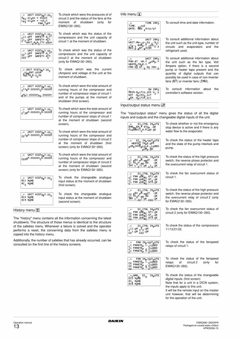
History menu ‚
The "history" menu contains all the information concerning the latestshutdowns. The structure of those menus is identical to the structureof the safeties menu. Whenever a failure is solved and the operatorperforms a reset, the concerning data from the safeties menu iscopied into the history menu.
Additionally, the number of safeties that has already occurred, can beconsulted on the first line of the history screens.
Info menu ™
Input/output status menu Ÿ
The "input/output status" menu gives the status of all the digitalinputs and outputs and the changeable digital inputs of the unit.
To check which were the pressures of ofcircuit 2 and the status of the fans at themoment of shutdown (only forEWAQ130~260).
To check which was the status of thecompressors and the unit capacity ofcircuit 1 at the moment of shutdown.
To check which was the status of thecompressors and the unit capacity ofcircuit 2 at the moment of shutdown(only for EWAQ130~260).
To check which was the current(Ampere) and voltage of the unit at themoment of shutdown.
To check which were the total amount ofrunning hours of the compressor andnumber of compressor stops of circuit 1and of the pumps at the moment ofshutdown (first screen).
To check which were the total amount ofrunning hours of the compressor andnumber of compressor stops of circuit 1at the moment of shutdown (secondscreen).
To check which were the total amount ofrunning hours of the compressor andnumber of compressor stops of circuit 2at the moment of shutdown (firstscreen) (only for EWAQ130~260).
To check which were the total amount ofrunning hours of the compressor andnumber of compressor stops of circuit 2at the moment of shutdown (secondscreen) (only for EWAQ130~260).
To check the changeable analogueinput status at the moment of shutdown(first screen).
To check the changeable analogueinput status at the moment of shutdown(second screen).
_÷ UNIT HISTORY:002
HP2:019$0b = 050$0¢
LP2:019$0b = -05$2¢
FAN2:OFF
_÷ UNIT HISTORY:002
C11:OFF SAFETY ACT.
C12:OFF SAFETY ACT.
UNITCAPACITY:000%
_÷ UNIT HISTORY:002
C21:OFF SAFETY ACT.
C22:OFF SAFETY ACT.
_÷ UNIT HISTORY:002
CURRENT:055A
VOLTAGE:023V
_÷ UNIT HISTORY:002
C11RH:00000hCS:00000
RHP1:00000hP2:00000h
_÷ UNIT HISTORY:002
C12RH:00000hCS:00000
_÷ UNIT HISTORY:002
C21RH:00000hCS:00000
_÷ UNIT HISTORY:002
C22RH:00000hCS:00000
_÷ UNIT HISTORY:002
AI1 NONE
AI2 NONE
_÷ UNIT HISTORY:002
AI3 NONE
AI4 NONE
To consult time and date information.
To consult additional information aboutthe unit such as the unit type, number ofcircuits and evaporators and therefrigerant used.
To consult additional information aboutthe unit such as the fan type, VoltAmpere option, if there is a secondpump or heater tape present and thequantity of digital outputs that canpossibly be used in case of non-inverterfans (ST) or inverter fans (INV).
To consult information about thecontroller's software version.
To check whether or not the emergencystop device is active and if there is anywater flow to the evaporator.
To check the status of the heater tapeand the state of the pump interlock andpump.
To check the status of the high pressureswitch, the reverse phase protector andthe overcurrent relay of circuit 1.
To check the fan overcurrent status ofcircuit 1.
To check the status of the high pressureswitch, the reverse phase protector andthe overcurrent relay of circuit 2 (onlyfor EWAQ130~260).
To check the fan overcurrent status ofcircuit 2 (only for EWAQ130~260).
To check the status of the compressors11/12/21/22.
To check the status of the fanspeedrelays of circuit 1.
To check the status of the fanspeedrelays of circuit 2 (only forEWAQ130~260).
To check the status of the changeabledigital inputs. (first screen)Note that for a unit in a DICN system,the inputs apply to this unit.It will be the remote input on the masterunit however, that will be determiningfor the operation of the unit.
_v TIME INFO
TIME: 22h05
DATE: WED 24/01/07
_÷ UNIT INFO
UNIT:AW-CO-260 C:SCL
CIR:2 EVAP:1 COILC:2
EEV:P REF:R410A
_÷ UNIT INFO
FAN:ST VA:Y 2PUMP:Y
HEATERTAPE:Y
FAN DO ST:2 DO INV:2
_^ SW INFO
MAIN:SP1710_055 V2.0
EXT :SP1559_017
REM.:SP1734_011
_v DIGITAL INPUTS
EMERGENCY STOP :OK
FLOWSWITCH:FLOW OK
_÷ DIG.INP/OUTPUTS
HEATER TAPE:OFF
PUMPINTERLOCK:CLOSED
PUMP:ON
_÷ DIGITAL INPUTS
C1 REV.PH.PROT. :OK
C1 HIGH PR.SW. :OK
INT.L C11:OK C12:OK
_÷ DIGITAL INPUTS
C1 FAN OVERC.ST1:OK
C1 FAN OVERC.ST2:OK
C1 FAN OVERC.ST3:OK
_÷ DIGITAL INPUTS
C2 REV.PH.PROT. :OK
C2 HIGH PR.SW. :OK
INT.L C21:OK C22:OK
_÷ DIGITAL INPUTS
C2 FAN OVERC.ST1:OK
C2 FAN OVERC.ST2:OK
C2 FAN OVERC.ST3:OK
_÷ DIGITAL INPUTS
C11:ON C12:ON
C21:ON C22:ON
_÷ FAN INP/OUTPUTS
C1 FANSTEP 1:CLOSED
C1 FANSTEP 2:CLOSED
C1 FANSTEP 3:CLOSED
_÷ FAN INP/OUTPUTS
C2 FANSTEP 1:CLOSED
C2 FANSTEP 2:CLOSED
C2 FANSTEP 3:CLOSED
_÷CHANG. DIG. INPUTS
DI1 NONE
DI2 NONE
DI3 NONE
Operation manual
13EWAQ080~260DAYN
Packaged air-cooled water chillers4PW35556-1E

User password menu Æ
Network menu ∆
The "network" menu (only available in case DICN is installed)provides useful information regarding the network.
Cool/heat menu Í
This menu is not available for EWAQ units.
Tasks of the usersettings menu
Entering the usersettings menu
The usersettings menu is protected by the user password, a 4-digitnumber between 0000 and 9999.
1 Enter the Å USERSETTINGS MENU. (Refer to the chapter"How to enter a menu" on page 8).
The controller will request the password.
2 Enter the correct password using the fi and Ì keys and press‡ for each digit.
3 Press ‡ on the last digit to confirm the password and to enterthe usersettings menu.
The controller automatically shows the submenu screen.
To define settings of a certain function:
1 Go to the appropriate submenu of the usersettings menu usingthe fi and Ì keys.
2 Press the ‡ key to enter the submenu of your choice.
3 Go to the appropriate screen using the fi and Ì keys. If thereis only one screen, the fi and Ì keys have no effect.
4 Press the ‡ key to move the cursor to the first parameter whichcan now be modified.
5 Select the appropriate setting using the fi and Ì keys.
6 Press ‡ to confirm the selection.
When the selection has been confirmed, the cursor switches tothe next parameter which can now be modified.
7 Repeat instruction 6 to modify the other parameters.
8 After the last parameter the cursor is switched back to thestarting position and continue from instruction 3 onwards.
9 Press the ƒ key to return to the usersettings menu andcontinue from instruction 1 onwards.
Submenu: Thermostat
Defining the thermostat settings
When inlet or outlet control mode is selected, the unit uses athermostat function to control the cooling capacity. However, thethermostat parameters are not fixed and can be modified.
The default, limit and step values for the thermostat parameters areshown in "Annex I" on page 25.
Defining and activating the control mode
The unit is equipped with a thermostat which controls the coolingcapacity of the unit. Select the appropriate mode:
■ MANUAL CONTROL:manual control mode: the operator controlsthe capacity himself by setting:• C11/12/21/22 (capacity step in manual mode): OFF or ON of
compressors 11/12/21/22.
• F1*, F2* (air flow in manual mode): off, low, medium or high ofcircuit 1/2.
■ INL WATER: inlet control mode: uses the entering watertemperature to control the capacity of the unit.
■ OUTL WATER: outlet control mode: uses the leaving watertemperature to control the capacity of the unit.
To check the status of the changeabledigital inputs and outputs (secondscreen).
To check the status of the changeabledigital outputs (third screen).
To check the status of the changeabledigital outputs and analogue inputs(fourth screen).
To check the status of the changeableanalogue inputs and outputs (fifthscreen)
To overview which communication linesare active.
To change the user password.
To define the user login and logoutstatus.
To change the login/logout password.
To consult the temperature setpoint, thecommon entering water temperature(entering water temperature of themaster unit).
The status screen of the network menushows the condition of the master unit(M) and slave units (SL1 ... SL3).
_÷CHANG. DIG. INPUTS
DI4 NONE
DO1 SAFETY+W.(NO) :O
DO2 GEN.OPERATION :O
_÷CHANG. INP/OUTPUTS
DO3 NONE (OPEN)
DO4 NONE (OPEN)
DO5 NONE (OPEN)
_÷CHANG. INP/OUTPUTS
DO6 NONE (OPEN)
AI1 NONE
AI2 NONE
_÷CHANG. INP/OUTPUTS
AI3 NONE
AI4 NONE
AO1 NONE
_^ COMMUNICATION
RS232 ONLINE:N
RS485 ONLINE:N
DIII ONLINE:N
ENTER PASSWORD
PASSWORD: 0000
TO LOGIN
_v LOGIN/LOGOUT MENU
LOGIN STATUS:USER
LOGOUT? NO
_^ LOGIN/LOGOUT MENU
CHANGE PASSWORD
NEW PASSWORD: 0000
CONFIRM: 0000
_v NETWORK
COOL. INLSP1:012$0¢
INLET WATER:013$6¢
OUTLET WATER:007$0¢
_^M:NORMAL CAP:000%
SL1:NORMAL CAP:000%
SL2:NORMAL CAP:000%
SL3:NORMAL CAP:000%
NOTE ■ If changed on one of the units in a DICNconfiguration, this setting is transferred to all otherunits in the network.
■ A functional diagram showing the thermostatparameters can be found in "Annex I" on page 25.
EWAQ080~260DAYNPackaged air-cooled water chillers4PW35556-1E
Operation manual
14

Submenu: Compressor
Defining the lead-lag settings
In the COMPR.LEAD-LAG screen select the appropriate mode anddefine the compressor lead-lag settings.
■ MODE
• AUTO: the priority is depending on the running hours of theseparate compressors.
• PRIORITY: C11>C12>C21>C22 the setting in this exampleC11 has the highest priority to startup while C22 has the lowestpriority.
Defining the capacity limitation settings
In the COMPR.CAP.LIMIT screen up to 4 possible capacitylimitation settings can be configured.
A capacity limitation can be activated:
■ MODE:• NOT ACTIVE: the capacity limitation is not active.
• CHANG.DIG.INP.: when a changeable input is configured ascapacity limitation.
• LIMIT 25%/50%/75%/SET: to activate capacity limitation.
■ in case of CHANG.DIG.INP. or LIMIT SET mode, eachcompressor must be defined (C11/12/21/ 22).
■ OFF: These compressors will always be switched off
■ ON: These compressors will still be used by the thermostataccording to the required load.
Submenu: Fan
Defining the fan low noise settings
The FAN LOW NOISE screen is only available when the optioninverter fans is installed (OPIF). Refer to the manual delivered withthe option.
Fan forced on settings
Allow to run the fans even when the unit is switched off.
■ OFF: the fans will not be activated.
■ ON: the fans will be forced to run.
■ CH.DIG.INP.: the fans will run, depending on the settings ofthe changeable digital input.
Submenu: Pump
Defining the pump control settings
The PUMPCONTROL screen of the usersettings menu allows the userto define the pump-leadtime and pump-lagtime.
■ PUMPLEADTIME: used to define the time that the pump mustrun before the unit (or the compressor in case PUMP ON IF:COMPR ON is selected in a DICN configuration) can start up.
■ PUMPLAGTIME: used to define the time that the pump keepsrunning after the unit (or the compressor in case PUMP ON IF:COMPR ON is selected in a DICN configuration) has beenstopped.
■ DAILY ON: select either Y (yes) or N (no). When Y is selected,define the starting time (24 hour time scale).This means that during that time, the pump will run for about5 seconds, even when the unit is switched off.
Defining dual pump control
The DUAL PUMP screen of the usersettings menu allows the user todefine the steering of two pumps (for this to be possible a changeabledigital output has to be configured for a second pump in the servicemenu). Refer to the installation manual.
■ MODE: used to define which kind of control will be used for thetwo pumps. When automatic rotation is chosen the offset onrunning hours also has to be entered.• AUTO ROTATION: pump 1 and pump 2 will alternate to the
offset on RH.
• PUMP 1>PUMP 2: pump 1 will always start up first.
• PUMP 2>PUMP 1: pump 2 will always start up first.
■ OFFSET ON RH: used to define the offset in running hoursbetween the two pumps. Used to switch over between pumpswhen they work in automatic rotation mode.
Submenu: Floating setpoint
Defining the floating setpoint settings
Setpoint signal is renamed as "floating setpoint based on changeableanalogue input".
The FLOATING SETPOINT screen of the usersettings menu allowsthe active setpoint to be modified in function of the ambienttemperature. The source and settings of the floating setpoint can beconfigured by the user.
■ MODE: used to define the mode of the floating setpoint.• NOT ACTIVE: floating setpoint is not activated.
• AMBIENT: floating setpoint is based on the ambient temperatureand altered accordingly. Settings: MAXPOS, NEG, RF or SLOPE.
• CH. AI SLOPE NTC: floating setpoint is based on thechangeable analogue input (NTC type) and altered accordingly.Settings: MAXPOS, NEG, RF or SLOPE.
• CH. AI SLOPE V-A: floating setpoint is based on thechangeable analogue input (V-A type) and altered accordingly.Settings: MAXPOS, NEG, RF or SLOPE.
• CH.AI MAX VALUE: floating setpoint is based on thechangeable analogue input (V-A type) and altered accordingly.Setting: MAXIMUM VALUE.
NOTE To activate manual control mode, select MANUALCONTROL as present mode. To deactivate the manualcontrol mode, select an other mode as present mode.
For units in a DICN configuration:
When changing the control mode on one of the units, itis automatically transferred to all other units.
Manual control mode however can only be selected onunits with status DISCONNECT ON/OFF.
NOTE The OUTLET mode is not available for DICN systems.
NOTE Refer to "Customization in the service menu",chapter "Setting of the changeable digitalinputs and outputs" in the installation manual.
NOTE A functional diagram showing the floating setpointworking can be found in "Annex II" on page 26.
Operation manual
15EWAQ080~260DAYN
Packaged air-cooled water chillers4PW35556-1E

Submenu: Language
Defining the language
This screen allows the user to define the language of the displayedinformation of the controller (on the first screen). (Push the ‡ buttonrepeatedly to change the operating language).
Submenu: Time and date
Defining the time and date
The TIME AND DATE screen of the usersettings menu allows theuser to define the time and date.
■ TIME: used to define the present time.
■ DATE FORMAT: used to define the format of the date.
■ DATE: select the name of the present day and define thepresent date according to the setting of the DATE FORMAT.DD = number of day (01~31),MM = number of month (01~12)YY = the last 2 numbers of the year (2006 = 06).
Submenu: Free cooling
Defining free cooling
The FREE COOLING screen of the usersettings menu allows theuser to control a 3-way water valve when the unit is in free coolingstate. To make this possible a changeable digital input or output hasto be configured for free cooling in the service menu. (Refer to theinstallation manual.)
■ MODE: used to define the free cooling mode.• NOT ACTIVE: free cooling is not active.
• CHDI: changeable digital input will activate the free cooling mode
• AMBIENT: free cooling is based on ambient temperature.
• INLET-AMBIENT: free cooling is based on the differencebetween inlet water temperature and ambient temperature.
■ SP: setting of the free cooling setpoint.
■ DIF: setting of the free cooling difference.
■ PUMP
■ ON: pump will be on when free cooling mode is active
■ OFF: pump will be off when free cooling mode is active
■ LEAD: time that the pump will be running before the compressorwill start operating.
Submenu: DICN
Only available in case DICN (option kit EKACPG) is installed (refer to"Connection and setup of a DICN system" in the installation manualand the installation manual of the EKACPG kit).
Defining the network settings
The SETTINGS screen of the network menu allows the user to setthe MODE of the unit, the OFFSET time and the condition when thepump must operate.
■ MODE: Define the mode of the unit as NORMAL, STANDBY orDISCONN ON/OFF.• NORMAL: The unit is controlled by the network. Loading and
unloading is decided by the central control of the netwerk. Puttingthis unit ON or OFF will also put all other units ON or OFF, unlesstheir status is DISCONNECT ON/OFF. (see further)Changing CONTROL SETTINGS or THERMOSTAT
SETTINGS to this unit, will apply to all other units. MANUALCONTROL on such a unit is not possible. Refer to "Defining andactivating the control mode" on page 14.
• STANDBY: The unit is considered as a NORMAL unit and itsfunction is then also similar to a unit defined as NORMAL, but thisunit however, will only come into operation if:another unit is in alarmanother unit is in DISCONNECT ON/OFF modethe setpoint is not reached when all other units have beenrunning on full capacity for some timeIf more than one unit is defined as STANDBY, only 1 of the unitswill be really standby. The unit which is really standby will bedecided by the number of running hours.
• DISCONNECT ON/OFF: Putting this unit ON or OFF will not putother units ON or OFF. MANUAL CONTROL on such a unit ispossible.If the unit is put to INLET or OUTLET mode, and the unit is ON,it will be controlled by the DICN network as a NORMAL unit.
■ OFFSET: The OFFSET time defines the target difference inrunning hours between one unit and another unit withOFFSET:0000h. This value is important for maintenancepurposes. The difference in setting among different units shouldbe high enough as to avoid servicing of the units all at the sametime. The lower and upper limits are 0 and 9000 hoursrespectively. The default value is 0 hours.
■ PUMP ON IF: Set if the pump must operate as long as thechiller is on (UNIT ON), or during compressor on condition only(COMPR ON).When UNIT ON is selected, the pump output will remain closedas long as the chiller is on. When COMPR ON is selected, thepump output will remain closed as long as the compressor is on.Also refer to the separate manual "Installation examples for aDICN configuration".
Submenu: Advanced
Activating or deactivating the setpoints password and the unit on/off password
The first ADVANCED screen of the usersettings menu allows the userto activate or deactivate the user password needed to change thetemperature setpoint (SETPOINT MENU). When deactivated, theuser does not have to enter the password each time he wants tochange the setpoint.
The first ADVANCED screen of the usersettings menu also allows theuser to activate or deactivate the user password needed to switch theunit ON or OFF (UNIT ON/OFF).
NOTE A functional diagram showing the free cooling workingcan be found in "Annex III" on page 26.
NOTE Put a unit to DISCONNECT ON/OFF when servicingthe machine. In this case it is possible to switch ON orOFF this unit without switching ON or OFF the otherunits of the network.
It is also possible then to operate the unit in MANUALCONTROL.
Put a unit to DISCONNECT ON/OFF continuously ifthe operator wants to decide by himself when this unitmust operate.
Note that in this case, it makes no sense to defineanother unit of the network as STANDBY. Since there isa unit set continuously to DISCONNECT ON/OFF, theSTANDBY unit will continuously be considered as aNORMAL unit.
NOTE The settings on this screen of the network menu mustbe executed for all chillers connected to the system.
NOTE If changed on one of the units in a DICN configuration,this setting is automatically transferred to all the otherunits in the network.
EWAQ080~260DAYNPackaged air-cooled water chillers4PW35556-1E
Operation manual
16

Defining controller settings
The second ADVANCED screen of the usersettings menu also allowsthe user to define settings for the controller.
■ MAIN MENU: set to GRAPHIC to let the main menu show thegraphical symbols or to TEXT to let the main menu show thenames of the menus.
■ LOGOUT TIMER: set the time for automatic log out, between 01and 30 minutes.
■ BUZZER IF SAFETY: to activate or deactivate the buzzersound when an error should occur.
■ BACKLIGHT TIME: to define the time (between 01 and 30minutes) the light of the controller display will stay on after thelast manipulation of the controller buttons.
■ GRAPHIC READOUT: to define if the graphical representation ofthe first screen of the read out menu is present or not.
Submenu: Defrost
This submenu is not available for EWAQ units.
Submenu: Service menu
Only a qualified installer is allowed to enter the service menu.
Tasks of the timers menu
Checking the actual value of the software timers
As a protective measure and to ensure correct operation, thecontroller's software features several countdown timers:
■ LOADUP (LOADUP – refer to the thermostat parameters): startscounting when a thermostat step change has occurred. Duringthe countdown, the unit is not able to enter a higher thermostatstep.
■ LOADDOWN (DWN – refer to the thermostat parameters): startscounting when a thermostat step change has occurred. Duringthe countdown, the unit will not be able to go to a lower thermo-stat step.
■ FLOWSTART (FLOWSTART – 15 sec): counts down when thewater flow through the evaporator is continuous and the unit is instandby. During the countdown, the unit cannot start up.
■ FLOWSTOP (FLOWSTOP – 5 sec): starts counting when thewater flow through the evaporator stops after the flowstart timerhas reached zero. If the water flow has not restarted during thecountdown, the unit will shut down.
■ PUMPLEAD (PUMPLEAD – refer to the pump control settings):starts counting whenever the unit is switched on. During thecountdown, the unit cannot start up.
■ PUMPLAG (PUMPLAG – refer to the pump control settings):starts counting whenever the unit is switched off. During thecountdown, the pump keeps running.
■ GUARDTIMER (GRD11/12/21/22 – 180 sec): starts countingwhen the compressor (circuit 1/2) has been shut down. Duringthe countdown, the compressor cannot be restarted.
■ ANTIRECYCLING (AREC11/12/21/22 – 300 sec): startscounting when the compressor (circuit 1/2) has started. Duringthe countdown, the compressor cannot be restarted.
■ MINIMUM RUNNING TIME (M.RT - 120 sec) starts countingwhen the compressor has started. During the count down, thecompressor will not be switched off by the thermostat function.
To check the actual value of the software timers, proceed as follows:
1 Enter the TIMERS MENU. (Refer to the chapter "How to enter amenu" on page 8.)
The controller displays the actual value of the GENERALTIMERS: the loadup timer, the loaddown timer, the flowstarttimer, the flowstop timer (when the unit is on and the flowstarttimer has reached zero), the pumplead timer and the pumplagtimer.
2 Press the Ì key to check the compressor timers.
The controller shows the actual value of the COMPRESSORTIMERS: the guard timers (one per circuit) and the antirecyclingtimers (one per circuit).
Tasks of the safety menu
Listing activated safeties and checking the unit status
If the alarm buzzer is activated and the user presses the π key, thecontroller automatically enters the safeties menu.
All active safeties are displayed: UNIT/CIRCUIT 1/2, WARNING orNETWORK SAFETY.
■ The controller will show the UNIT SAFETY screen of thesafeties menu when a unit safety was the cause of shutdown.
■ The controller will show the CIRCUIT 1/2 SAFETY screen ofthe safeties menu when a safety of the circuit 1/2 was activated.
■ The controller will show the NETWORK SAFETY screen of thesafeties menu when a safety of the network was activated.
■ The controller will show the UNIT WARNING screen of thesafeties menu when a unit warning was activated.
1 Press the π key when the alarm buzzer is activated.
The appropriate safety screen with the basic informationappears. Press the ‡ key to go directly to the history menu andsee the detailed information. These screens provide informationabout the unit status at the moment of shutdown (see "Safetymenu π" on page 12).
2 If more than one kind of safety is active (indicated by means of^, v or ÷), use the fi and Ì keys to consult them.
Tasks of the history menu
Checking the safety info and the unit status after a reset
The information available in the safeties menu is also stored in thehistory menu, where it is stored after resetting the unit or the circuit.In this way, the history menu provides a means of checking the unitstatus at the moment of the latest shutdown.
To check the safety info and the unit status, proceed as follows:
1 Enter the HISTORY MENU. (Refer to the chapter "How to entera menu" on page 8.)
The controller enters the last HISTORY screen which containsbasic information of the moment of this shutdown.
2 Press the fi and Ì keys to consult the other present HISTORYscreens.
3 Press the ‡ key to see the detailed information.
NOTE If changed on one of the units in a DICN configuration,this setting is automatically transferred to all the otherunits in the network.
Operation manual
17EWAQ080~260DAYN
Packaged air-cooled water chillers4PW35556-1E

Tasks of the info menu
Consulting additional unit information
1 Enter the INFO MENU through the main menu. (Refer to thechapter "How to enter a menu" on page 8).
The controller enters the TIME INFO screen which contains thefollowing information: the TIME and DATE.
2 Press Ì to consult the first UNIT INFO screen.
This screen contains information about the unit name, number ofcircuits, evaporators and coils, EEV and the refrigerant used.
3 Press Ì to consult the second UNIT INFO screen.
This screen contains information about the fans, volt/ampereand if there is a second pump or heater tape applied.
4 Press Ì to consult the SW INFO (software information) screen.
This screen contains information about the PCB softwareversions.
Tasks of the input/output menu
Checking the status of the inputs and outputs
The input/output menu provides a means of checking the status ofthe digital inputs and the status of the relay outputs.
The locked digital inputs are:
■ EMERGENCY STOP: whether the emergency button has beenpressed (only effective if there is an emergency stop present).
■ FLOWSWITCH: indicates the status of the flowswitch (flow/noflow).
■ HEATER TAPE: indicates if the heater tape is activated or not.
■ PUMPINTERLOCK: indicates if the status of the pump interlockis open or closed.
■ PUMP: indicates if the pump is on or off.
■ C1/2 REV.PH.PROT.: (reverse phase protector) indicates theactual status of this safety of circuit 1/2.
■ C1/2 HIGH PR.SW.: (high pressure switch) indicates theactual status of this safety of circuit 1/2.
■ INT.L C11/C12/C21/22: (interlock to compressor) indicatesthe actual status of this safety of circuit1/2.
■ C1/2 FANOVERC. ST. 1/2/3: (fan overcurrent statusstep 1/2/3) indicates the actual status of this safety of circuit 1/2.
The locked relay outputs are:
■ C11/12/21/22: indicates whether the circuit 1/2 is on or off.
■ C1/2 FANSTEP 1/2/3: indicates if the fans of fanstep 1/2/3 forthe circuit 1/2 are on or not.
Checking the status of the digital changeable inputs and outputs
The possible settings for the changeable digital inputs are:
■ NONE: indicates there is no function selected for this input
■ STATUS: indicates the position of the connected switch.
■ DUAL SETPOINT: indicates the position of the remote dualsetpoint switch: setpoint 1 or setpoint 2.
■ REMOTE ON/OFF: indicates the position of the remote on/offswitch.
■ CAP LIMIT 25%/50%/75%/SET: indicates the position of the"enable/disable capacity limitation" switches.
■ LOW NOISE: indicates the status of the low noise mode.
■ FREE COOLING REQ: indicates if the free cooling is requestedor not requested.
■ FAN FORCED ON: indicates if the fan forced on is activated ornot activated.
The possible settings for the changeable relay outputs are:
■ NONE (OPEN): Digital output open.
■ CLOSED: Digital output closed.
■ 2ND PUMP: indicates the status of the second pump.
■ 100% CAPACITY: indicates when the unit is working at 100%.
■ FULL CAPACITY: indicates when the unit is working atmaximum capacity, example reached 100% capacity or reachedmaximum capacity because of safety limitation.
■ FREE COOLING: indicates the status of the 3-way water valvewhen the unit is in free cooling state.
■ GEN.OPERATION: indicates when the unit is active.
■ SAFETY+W (NO): indicates when safety or warning is active(Normal Open contact).
■ SAFETY+W (NC): indicates when safety or warning is active(Normal Closed contact).
■ SAFETY (NO): indicates when safety is active (Normal Opencontact).
■ SAFETY (NC): indicates when safety is active (Normal Closedcontact).
■ C1/2 SAFETY: indicates when circuit 1/2 safety is active.
■ WARNING: indicates when warning is active.
■ C1/2 OPERATION: indicates when circuit 1/2 operation isactive.
Checking the status of the analogue changeable inputs and output
The possible settings for the analogue changeable inputs and outputare:
■ NONE: no function is appointed to the changeable analogueinput.
■ STATUS: only displays the status by means of test
■ FLOATING SETP: floating setpoint based on ambient oranalogue input
■ TEMPERATURE: only displays the (by example) condenseroutlet temperature
■ DI***: refer to the possible functions for changeable digitalinputs. (*** can be any of the following: STATUS, DUALSETPOINT, REMOTE ON/OFF, CAP. LIMIT, LOW NOISE,FREE COOLING REQ or FAN FORCED ON.)
Checking the communication inputs and outputs (option EKACPG)
The communication inputs and outputs are:
■ RS232 ONLINE: indicates if the RS232 communication line isactive.
■ RS485 ONLINE: indicates if the RS485 communication line isactive.
■ DIII ONLINE: indicates if the DIII communication line isactive.
To check the inputs and outputs, proceed as follows:
1 Enter the I/O STATUS MENU. (Refer to the chapter "How toenter a menu" on page 8.)
The controller enters the first DIGITAL INPUTS screen.
2 Consult the other screens of the input/output menu using the fiand Ì keys.
EWAQ080~260DAYNPackaged air-cooled water chillers4PW35556-1E
Operation manual
18

Tasks of the login/logout menu
Changing the user password
Access to the usersettings menu and the setpoints menu is protectedby the user password (a 4-digit number between 0000 and 9999).
After the password is entered, other protected screens do no longerrequire the entering of the password.
To log out, go to the login/logout menu and alter the login status andthe logout setting.
To change the user password, proceed as follows:
1 Enter the USERPASSWORD MENU. (Refer to the chapter "Howto enter a menu" on page 8).
The controller will request the password.
2 Enter the actual correct password using the fi, Ì and ‡ keys.
For each of the 4 digits:- Use the fi and Ì keys to select the correct number.- Press the ‡ key to enter and select the next number.
When pressing the ‡ key on the last number, the completepassword is entered.
3 After the ‡ key has been pressed to confirm the password, thecontroller shows the first login/logout screen.
The login status is shown.The logout is set to NO.
4 When the setting for logout must change to YES.
- Press the ‡ key to position the cursor behind LOGOUT?- Press the fi or Ì keys to change the setting to YES.- Press the ‡ key to confirm the setting.
The controller leaves the login/logout screen and shows the firstscreen of the read out menu.
5 When the setting for logout stays NO, press the Ì key to enterthe second login/logout screen.
The controller requests for a new password.
6 Press the ‡ key to position the cursor behind NEW PASSWORD.
7 Enter the new password using the fi, Ì and ‡ keys.
For each of the 4 digits:- Use the fi and Ì keys to select the correct number.- Press the ‡ key to enter and select the next number.
When pressing the ‡ key on the last number, the complete new password is entered and the cursor is positioned behind CONFIRM.The controller requests to confirm the new password.
8 Enter the new password again using the fi, Ì and ‡ keys.
For each of the 4 digits:- Use the fi and Ì keys to select the correct number.- Press the ‡ key to enter and select the next number.
When pressing the ‡ key on the last number, the confirmation of the new password is completed.
TROUBLESHOOTING
This section provides useful information for diagnosing andcorrecting certain troubles which may occur in the unit.
Before starting the trouble shooting procedure, carry out a thoroughvisual inspection of the unit and look for obvious defects such asloose connections or defective wiring.
Before contacting your local dealer, read this chapter carefully, it willsave you time and money.
Overview of safety messages
NOTE The default user password is 1234.
NOTE The actual password will only be changed when thenew password and the confirmed password have thesame value.
If changed on one of the units in a DICN configuration,this setting is automatically transferred to all the otherunits in the network.
When carrying out an inspection on the supply panel or onthe switch box of the unit, always make sure that the circuitbreaker of the unit is switched off.
Message safety menu Symptom
UNIT SAFETY 0AE:FLOW HAS STOPPED 5.2
0AE:PUMPINTERLOCK 5.3
0A4:FREEZE UP 5.1
0A4:FREEZE UP C1 5.1
0A4:FREEZE UP C2 5.1
0A9:EEV PCB COMM ERR 5.5
0A9:EEV PCB ERR 5.5
0C9:INL SENSOR ERR 7
0CA:OUT SENSOR ERR 7
0H9:AMB T SENSOR ERR 7
0U4:EXTPCB COMM.ERR 9
0U4:MAINPCB COMM.ERR 10
0U5:PCB COMM.PROBLEM 11
CIRCUIT 1
SAFETY
153:FAN OVERC. ST1 5.4
153:FAN OVERC. ST2 5.4
153:FAN OVERC. ST3 5.4
1A9:EEV ERR 5.5
1A9:SUPERHEAT ERR 5.6
1E3:HIGH PRESSURE SW 5.7
1E4:LOW PRESSURE 5.8
1E6:COMPR 1 SAFETY 5.9b/5.10
1E6:COMPR 2 SAFETY 5.9b/5.10
1F3:HIGH DISCH TEMP1 5.11
1F3:HIGH DISCH TEMP2 5.11
1J3:DISCHSENSOR ERR1 7
1J3:DISCHSENSOR ERR2 7
1J5:REFR SENSOR ERR 7
1J5:SUCTSENSOR ERR 7
1JA:HP SENSOR ERR 7
1JC:LP SENSOR ERR 7
1U1:REV PHASE PROT 5.12
CIRCUIT 2
SAFETY
253:FAN OVERC. ST1 5.4
253:FAN OVERC. ST2 5.4
253:FAN OVERC. ST3 5.4
2A9:EEV ERR 5.5
2A9:SUPERHEAT ERR 5.6
2E3:HIGH PRESSURE SW 5.7
2E4:LOW PRESSURE 5.8
2E6:COMPR 1 SAFETY 5.9b/5.10
2E6:COMPR 2 SAFETY 5.9b/5.10
2F3:HIGH DISCH TEMP1 5.11
2F3:HIGH DISCH TEMP2 5.11
2J3:DISCHSENSOR ERR1 7
2J3:DISCHSENSOR ERR2 7
2J5:REFR SENSOR ERR 7
2J5:SUCTSENSOR ERR 7
2JA:HP SENSOR ERR 7
2JC:LP SENSOR ERR 7
2U1:REV PHASE PROT 5.12
Operation manual
19EWAQ080~260DAYN
Packaged air-cooled water chillers4PW35556-1E

When a safety device was activated, stop the unit and find out whythe safety device was activated before resetting it. Under no circum-stances safety devices may be bridged or changed to a value otherthan the factory setting. If the cause of the problem cannot be found,call your local dealer.
Symptom 1: The unit does not start, but the ON LED lights up
Symptom 2: The unit does not start, but the ON LED is flashing
Symptom 3: The unit does not start and the ON LED does not light up3
Symptom 4: The circuit does not start up
Symptom 5: Safety devices are activated and alarm messages are displayed
5.1
5.2
5.3
5.4
5.5
UNIT WARNING 0AE:FLOW HAS STOPPED 5.2
0C9:INL SENSOR ERR 7
1E3:HP SETBACK 5.7
153:FAN OVERC. ST1 5.4
153:FAN OVERC. ST2 5.4
153:FAN OVERC. ST3 5.4
2E3:HP SETBACK 5.7
253:FAN OVERC. ST1 5.4
253:FAN OVERC. ST2 5.4
253:FAN OVERC. ST3 5.4
NETWORK
SAFETY
0C9:INL SENSOR ERR 7
0U4:PCB COMM.PROBLEM 12
0U4:SW VERSION ERR 13
POSSIBLE CAUSES CORRECTIVE ACTION
The temperature setting is not correct.
Check the controller setpoint.
The flowstart timer is still running. The unit will start after approx. 15 seconds. Make sure that water is flowing through the evaporator.
The circuit can not start up. Refer to Symptom 4: The circuit does not start up.
Unit is in manual mode (all compressors at 0%).
Check on the controller.
Power supply failure. Check the voltage on the supply panel.
Blown fuse or interrupted protection device.
Inspect fuses and protection devices. Replace by fuses of the same size and type (refer to "Electrical specifications" on page 2).
Loose connections. Inspect connections of the field wiring and the internal wiring of the unit. Tighten all loose connections.
Shorted or broken wires. Test circuits using a tester and repair if necessary.
POSSIBLE CAUSES CORRECTIVE ACTION
The remote ON/OFF input is enabled and the remote switch is off.
Put the remote switch on or disable the remote ON/OFF input.
POSSIBLE CAUSES CORRECTIVE ACTION
The unit is in failure mode. Refer to Symptom 5: Safety devices are activated and alarm messages are displayed.
One of the following safety devices is activated:• Flowswitch (S8L,S9L)• Emergency stop
Refer to Symptom 5: Safety devices are activated and alarm messages are displayed.
The ON LED is broken. Contact your local dealer.
Message safety menu Symptom
POSSIBLE CAUSES CORRECTIVE ACTION
One of the following safety devices is activated:• Compressor thermal protector (Q*M)• Overcurrent relay (K*S)• Discharge thermal protector• Low pressure• High pressure switch (S*PH)• Reverse phase protector • Freeze-up
Check on the controller and refer to Symptom 5: Safety devices are activated and alarm messages are displayed.
The anti-recycling timer is still active. The circuit can only start up after approximately 5 minutes.
The guard timer is still active. The circuit can only start up after approximately 3 minutes.
The circuit is limited to 0%. Check the enable/disable capacity limitation remote contact.
Symptom 5.1: Freeze-up protection is activated(0A4:FREEZE UP)
POSSIBLE CAUSES CORRECTIVE ACTION
Water flow too low. Increase the water flow.
Inlet temperature to the evaporator is too low.
Increase the inlet water temperature.
Flow switch is not working or no water flow.
Check the flow switch and the water pump.
RESET After temperature increase the freeze-up is reset automatically, but the circuit controller needs to be reset.
Symptom 5.2: Flowswitch is activated (0AE:FLOW HAS STOPPED)
POSSIBLE CAUSES CORRECTIVE ACTION
No water flow or too low water flow. Check the water pump filter and the water circuit for obstructions.
RESET After finding the cause, the flowswitch is reset automatically, but the controller still needs to be reset.
Symptom 5.3: Pump interlock contact is open(0AE:PUMPINTERLOCK)
POSSIBLE CAUSES CORRECTIVE ACTION
The pump interlock contact is not closed.
Make sure a pump interlock contact is wired correctly and closed when the pump starts operating.
RESET Only if a pump contactor is present: Switch the black handle on the pump fuse inside the switchbox and reset the controller.
Symptom 5.4: Fan overcurrent is activated (153/253:FAN OVERC. 1/2/3)
POSSIBLE CAUSES CORRECTIVE ACTION
Mechanical failure (fan is blocked). Check that the fan rotates freely.
Air flow in the unit too low or outdoor temperature too high.
Clean the air heat exchanger properly.
RESET Push the blue button on the fan fuse inside the switchbox and reset the controller.
Symptom 5.5: EEV driver is not operating(0A9:EEV PCB (COMM) ERR, 1A9/2A9:EEV ERR)
POSSIBLE CAUSES CORRECTIVE ACTION
The EEV driver is not operating. Check the power supply to the EEV driver.Check if the address setting by DIP-switch is according to the wiring diagram.
EWAQ080~260DAYNPackaged air-cooled water chillers4PW35556-1E
Operation manual
20

5.6
5.7
5.8
5.9a
5.9b
5.10
5.11
5.12
Symptom 5.6: Superheat temperature is not correct(1A9/2A9:SUPERHEAT ERR)
POSSIBLE CAUSES CORRECTIVE ACTION
Superheat temperature is too high. Check if the unit has enough refrigerant (no foaming visible in sight glass).Check if the suction temperature sensor of the EEV driver is in the holder in the suction tube and not hanging loose.
Superheat temperature is too low. Check if the EEV driver or the control motor of EEV is wired correctly and operating.
The sensed suction temperature is more than 2°C higher than the entering water temperature of the evaporator.
Check if the suction temperature sensor of the controller is in its holder and not hanging loose.
Symptom 5.7: High-pressure switch and high pressure setback(1E3/2E3:HIGH PRESSURE SW, 1E3/2E3:HP SETBACK)
POSSIBLE CAUSES CORRECTIVE ACTION
Condenser fan does not operate properly.
Check that the fans turn freely. Clean if necessary.
Dirty or partially blocked condenser. Remove any obstacle and clean condenser coil using brush and blower.
Inlet air temperature of the condenser is too high.
The air temperature measured at the inlet of the condenser may not exceed 43°C.
Fan turning in the wrong direction. Two phases of the power supply to the fan motor must be inverted (by a licensed electrician).
RESET After pressure rise, this safety resets automatically, but the controller still needs to be reset.
Symptom 5.8: Low pressure (1E4/2E4:LOW PRESSURE)
POSSIBLE CAUSES CORRECTIVE ACTION
Water flow to water heat exchanger too low.
Increase the water flow.
Shortage of refrigerant. Check for leaks and refill refrigerant, if necessary.
Unit is working out of its operation range.
Check the operation conditions of the unit.
Inlet temperature to the water heat exchanger is too low.
Increase the inlet water temperature.
Dirty evaporator. Clean the evaporator, or call your local dealer.
Low pressure safety setting too high. Refer to the installation manual "Customization in the service menu", paragraph "Setting of the minimum outlet water temperature" for correct values.
Flowswitch is not working or no water flow.
Check the flowswitch and the water pump.
RESET After pressure rise, this safety resets automatically, but the controller still needs to be reset.
Symptom 5.9a: The compressor does not work (only for SJ161-4)(Compressor thermal protection is activated)
POSSIBLE CAUSES CORRECTIVE ACTION
The compressor motor coil temperature is too high because the compressor motor takes (demands/needs) too much current and is not sufficiently cooled by refrigerant.
Make sure there are no refrigerant leaks.After repairing leaks, charge the unit with additional refrigerant until the sight glass in the liquid line shows no foaming.
Make sure the unit operates within its operating range (too high ambient or too high water temperature).
Make sure the compressor motor is not locked.
RESET After temperature decrease the thermal protector is reset automatically and the compressor will start again. This is not detected by the controller.If the protector is activated frequently, call your local dealer.
Symptom 5.9b: Compressor safety (only for SJ161-4)(1E6/2E6:COMPR 1/2 SAFETY)
POSSIBLE CAUSES CORRECTIVE ACTION
Failure of one of the phases. Check fuses on the supply panel or measure the supply voltage.
Voltage too low. Measure the supply voltage.
The unit is working out of its range. Make sure the unit operates within its operating range.
Overload of motor. Reset. If the failure persists, call your local dealer.
There is a short circuit. Check the wiring.
RESET Pull the black handle on the compressor fuse inside the switch box and reset the controller.
Symptom 5.10: Compressor safety (only for SJ180-4~SJ240-4 and SJ300-4)(1E6/2E6:COMPR 1/2 SAFETY)
POSSIBLE CAUSES CORRECTIVE ACTION
The compressor motor coil temperature is too high because the compressor motor takes (demands/needs) too much current and is not sufficiently cooled by refrigerant.
Make sure there are no refrigerant leaks.After repairing leaks, charge the unit with additional refrigerant until the sight glass in the liquid line shows no foaming.
Make sure the unit operates within its operating range (too high ambient or too high water temperature).
Make sure the compressor motor is not locked.
RESET After temperature decrease, a 5 minute delay is activated. After this delay the relay in the electronic protection module (EPM) is pulled in. The controller needs to be reset manually.
Failure of one of the phases. Check fuses on the supply panel or measure the supply voltage.
Voltage too low. Measure the supply voltage.
The unit is working out of its range. Make sure the unit operates within its operating range.
Overload of motor. Reset. If the failure persists, call your local dealer.
The compressor is running in reverse phase (only for SJ240-SJ300)
Check the wiring.
There is a short circuit. Check the wiring.
RESET Pull the black handle on the compressor fuse inside the switch box and reset the controller.
Symptom 5.11: Discharge thermal protector is activated (1F3/2F3:HIGH DISCH TEMP1/2)
POSSIBLE CAUSES CORRECTIVE ACTION
Unit is working outside the operation range.
Check the operation condition of the unit.
The unit is undercharged. Check if there are no refrigerant leaks.After repairing leaks, charge the unit with additional refrigerant until the sight glass in the liquid line shows no foaming.
RESET After temperature decrease, the safety resets automatically but the controller still needs to be reset.
Symptom 5.12: Reverse phase protector is activated(1U1/2U1:REV PHASE PROT)
POSSIBLE CAUSES CORRECTIVE ACTION
Two phases of the power supply are connected in the wrong phase position.
Invert two phases of the power supply (by licensed electrician).
One phase is not connected properly.
Check the connection of all phases.
Voltage too low. Measure the supply voltage.
RESET After inverting two phases or fixing the power supply cables properly, the protector is reset automatically, but the controller still needs to be reset.
Operation manual
21EWAQ080~260DAYN
Packaged air-cooled water chillers4PW35556-1E

Symptom 6: Unit stops soon after operation6
Symptom 7: Sensor error 0C9/0CA/0H9:*** SENSOR ERR7
Symptom 8: The alarm message shows 0U3:REMOCON SW ERR8
Symptom 9: The alarm message shows 0U4:EXT PCB COMM.ERR9
Symptom 10: The alarm message shows 0U4:MAINPCB COMM.ERR10
Symptom 11: The alarm message shows 0U5:PCB COMM.PROBLEM11
Symptom 12: The NETWORK SAFETY alarm message shows 0U4:PCB COMM.PROBLEM
12
Symptom 13: The NETWORK SAFETY alarm message shows 0U4:SW VERSION ERR
13
Symptom 14: The water pressure can not be maintained
MAINTENANCE
In order to ensure optimal availability of the unit, a number of checksand inspections on the unit and the field wiring have to be carried outat regular intervals.
If the unit is used for air conditioning application, the describedchecks must be executed at least once a year. In case the unit isused for other applications, the checks must be executed every4 months.
Maintenance activities
■ Air heat exchangerRemove dust and any other contaminant from the coil fins usinga brush and a blower. Blow from the inside of the unit. Take carenot to bend or damage the fins.
■ Field wiring and power supply• Check the power supply voltage on the local supply panel. The
voltage must correspond to the voltage marked on the identifi-cation label of the unit.
• Check the connections and make sure they are properly fixed.
• Check the proper operation of the circuit breaker and the earthleak detector provided on the local supply panel.
■ Internal wiring of the unitVisually check the switch boxes on loose connections (terminalsand components). Make sure that the electrical components arenot damaged or loose.
■ Earth connectionMake sure that the earth wires are still connected properly andthat the earth terminals are tightened.
■ Refrigerant circuit• Check for leaks inside the unit. In case a leak is detected, call
your local dealer.
• Check the working pressure of the unit. Refer to "Switching theunit on" on page 8.
■ Compressor• Check on oil leaks. If there is an oil leak, call your local dealer.
• Check for abnormal noises and vibrations. If the compressor isdamaged, call your local dealer.
■ Fan motor• Clean the cooling ribs of the motor.
• Check on abnormal noises. If the fan or motor are damaged, callyour local dealer.
POSSIBLE CAUSES CORRECTIVE ACTION
One of the safety devices is activated.
Check safety devices (refer to Symptom 5: Safety devices are activated and alarm messages are displayed).
Voltage is too low. Test the voltage in the supply panel and, if necessary, in the electrical compartment of the unit (voltage drop due to supply cables is too high).
POSSIBLE CAUSES CORRECTIVE ACTION
The sensor is broken or not correctly wired.
Check if the wiring is according to the wiring diagram.Call your local dealer.
POSSIBLE CAUSES CORRECTIVE ACTION
The software for the wired remote controller (A4P or A5P) is corrupt or absent.
Check if the wiring to the main PCB (A11P) is according to the wiring diagram.Check if the "address setting" and the "terminator resistor setting" by DIP-switch is according to the setting mentioned in the wiring diagram.Call your local dealer.
POSSIBLE CAUSES CORRECTIVE ACTION
The extension PCB (A01P) can not be found.
Check if the wiring to the extension PCB (A01P) is according to the wiring diagram.Call your local dealer.
POSSIBLE CAUSES CORRECTIVE ACTION
The main PCB of circuit 2 (A21P) can not be found.
Check if the wiring to the main PCB of circuit 2 (A21P) is according to the wiring diagram.Check if the "address setting" and the "terminator resistor setting" by DIP-switch is according to the setting mentioned in the wiring diagram.Call your local dealer.
POSSIBLE CAUSES CORRECTIVE ACTION
The wired remote controller (A4P or A5P (EKRUPG)) has no correct communication with the main PCB (A11P).
Check if the wiring to the main PCB (A11P) is according to the wiring diagram.Check if the "address setting" and the "terminator resistor setting" by DIP-switch is according to the setting mentioned in the wiring diagram.Call your local dealer.
POSSIBLE CAUSES CORRECTIVE ACTION
The unit can not be found by the DICN system (EKACPG)
Check if the wiring between units is according to the wiring diagram.• Make sure all the units in the DICN system
are powered up.• Make sure that the correct number of slave
units is defined in the master unit.• Make sure that the correct unit address
setting is defined in each unit (refer to the installation manual).
POSSIBLE CAUSES CORRECTIVE ACTION
All units in the DICN system (EKACPG) do not have the same software version.
Check the software version of each unit.Call your local dealer in case a software upgrade is necessary.
POSSIBLE CAUSES CORRECTIVE ACTION
There is a leak in the water circuit. Check for any leaks in the water circuit.
The expansion vessel is broken or does not work properly.
Replace the expansion vessel.
Before carrying out any maintenance or repair activity,always switch off the circuit breaker on the supply panel,remove the fuses or open the protection devices of theunit.
Never clean the unit with water under pressure.
The wiring and power supply must be checked by alicensed electrician.
EWAQ080~260DAYNPackaged air-cooled water chillers4PW35556-1E
Operation manual
22

■ Water supply• Check if the water connection is still well fixed.
• Check the water quality (refer to the installation manual of the unitfor specifications of the water quality).
■ Water filters• Make sure to clean the water filter in front of the evaporator water
inlet once every 4 months.
• Check the filter for any possible damage and make sure that thehole diameter size all over the filter surface is still 1.0 mmmaximum.
■ Water sensorsCheck that all the water sensors are correctly fixed into the inletand outlet water pipe.
■ FlowswitchMake sure that there is no dirt accumulating on the paddle of theflowswitch.
■ Water pressureCheck if the water pressure is within acceptable range. Refer tothe installation manual delivered with the unit.
Disposal requirements
Dismantling of the unit, treatment of the refrigerant, of oil and of otherparts must be done in accordance with relevant local and nationallegislation.
NOTES
Operation manual
23EWAQ080~260DAYN
Packaged air-cooled water chillers4PW35556-1E

NOTES
EWAQ080~260DAYNPackaged air-cooled water chillers4PW35556-1E
Operation manual
24

ANNEX I
Thermostat parameters
Water temperature control
The figures below show the thermostat diagram in case of inlet water temperature control.
■ Stand alone thermostat(1) (inlet or outlet)
The default value and the upper and lower limits of thethermostat parameters are listed in the table below.
■ DICN thermostat(1) (inlet)
The default value and the upper and lower limits of thethermostat parameters are listed in the table below.
■ If the temperature is below the setpoint, the thermostat controlwill check every LOADDOWN TIMER. According to the deviation to the setpoint, no action, load up,down is required.
■ If the temperature is above the setpoint, the thermostat controlwill check every LOADUP TIMER. According to the deviation to the setpoint, no action, load up,down is required.
(1) Loadup request of 1 compressor: request to add one additional compressor.Loadup request of 2 compressors: request to add 2 additional compressors (with interval of 15 seconds inbetween).The maximum number of compressors that can possibly be added in 1 request is limited to the total number of units that are present in the DICN setup: Example: A DICN setup with 2 units means load up requests of maximum 2 compressors at a time.
INLET CONTROL
Default value
Lower limit
Upper limit
Units 1 circuit
Units 2 circuits
Step difference - a (K) 4.0(*)
(*) can only be modified in the service menu
2.0(*) — —
Steplength - c (K) 0.2(*) — —
Loadup timer (sec) 180 15 300
Loaddown timer (sec) 30 15 300
Setpoint (°C) 12.0 7.0 23.0
OUTLET CONTROL
Default value
Lower limit Upper limit
Units 1 circuit
Units 2 circuits
Step difference - a (K) 4.0(*)
(*) can only be modified in the service menu
2.0(*) — —
Steplength - c (K) 0.2(*) — —
Loadup timer (sec) 30 15 300
Loaddown timer (sec) 15 15 300
Setpoint (°C) 7.0 4.0 20.0
c c
a/2a/2 a/2a/2
c c
a/2 a/2
c c
a/2a/2 a/2a/2
c c
a/2 a/2
Inlet setpoint
Load up request of 1 compressor
no action
Load down request of 1 compressor
Outlet setpoint
INLET CONTROL Default value Lower limit Upper limit
Step difference - a (K) 4.0(*)
(*) can only be modified in the service menu
— —
Step difference - b (K) 3.6(*) — —
Step difference - c (K) 0.4(*) — —
Loadup timer (sec) 180 15 300
Loaddown timer (sec) 180 15 300
Setpoint (°C) 12.0 7.0 23.0
c c c cb b
a/2a/2 a/2a/2
c c c cb b
a/2 a/2
Inlet setpoint
Load up request of 4 compressors
Load up request of 3 compressors
Load up request of 2 compressors
Load up request of 1 compressor
no action
Load down request of 1 compressor
Load down request of 2 compressors
Load down request of 3 compressors
Load down request of 4 compressors
Operation manual
25EWAQ080~260DAYN
Packaged air-cooled water chillers4PW35556-1E

ANNEX II
Floating setpoint working
The diagrams and table below show the default value of the floatingsetpoint parameters on the evaporator and an example on the inletsetpoint of 12.0°C.
Legend
■ Floating setpoint based on ambient
■ Floating setpoint based on NTC
■ Floating setpoint based on Voltage or mAmpere
■ Floating setpoint based on changeable analogue input
ANNEX III
Free cooling working
Legend
Free cooling on ambient temperature
Free cooling on difference between inlet water evaporator temperature and ambient temperature
SLOPE The rise in floating setpoint value for a 10°C drop (floating setpoint based on ambient or NTC) or a drop of 100 (floating setpoint based on voltage or milliampere).
A Active setpoint
B Setpoint
Example ambient = 17.5°C
Example temperature = 17.5°C
Example = 35 (0.375 V, 10 mA)
_ FLOATING SETPOINT
MODE:AMBIENT
MAXPOS:03$0¢ NEG:00$0¢
RF:020$0¢ SLOPE:006$0¢
12.0°C
13.5°C
15.0°C
18.0°C
17.5°C10.0°C 20.0°C
+6.0°C
3.0°C
+10.0°C
A
B
AMBIENT
_ FLOATING SETPOINT
MODE:CH.AI SLOPE NTC
MAXPOS:03$0¢ NEG:03$0¢
RF:020$0¢ SLOPE:006$0¢
12.0°C
9.0°C
13.5°C
15.0°C
18.0°C
17.5°C10.0°C 20.0°C 25.0°C
+6.0°C
3.0°C
3.0°C
+10.0°C
A
B
CH.AI SLOPE NTC
_ FLOATING SETPOINT
MODE:CH.AI SLOPE V-A
MAXPOS:03$0¢ NEG:03$0¢
RF:020$0¢ SLOPE:012$0¢
12.0°C
9.0°C
6.0°C
13.5°C
15.0°C
18.0°C
35(0.375 V) (10 mA)
50(0.5 V) (12 mA)
100(1.0 V) (20 mA)
0(0.0 V)(4 mA)
+12.0°C
3.0°C
3.0°C
+100
A
B
CH.AI SLOPE V-A
Example = 50 (0.5 V, 12 mA)
SP Setpoint
DI Differential
Free cooling default minimum maximum
SP (°C) 5.0°C –30.0°C 25.0°C
DI (°C) 1.0°C 1.0°C 5.0°C
Free cooling default minimum maximum
SP (°C) 5.0°C 1.0°C 20.0°C
DI (°C) 5.0°C 1.0°C 10.0°C
_ FLOATING SETPOINT
MODE:CH.AI MAX VALUE
MAXIMUM VALUE:003$0¢
50(0.5 V) (12 mA)
100(1.0 V) (20 mA)
0(0.0 V)(4 mA)
12.0°C
13.5°C
15.0°C+3.0°CA
B
CH.AI. MAX VALUE
DISP °C
free cooling state
ambient temperature
ON
OFF
DISP °C
free cooling state
ON
OFF
inlet water evaporator temperature minus ambient temperature
EWAQ080~260DAYNPackaged air-cooled water chillers4PW35556-1E
Operation manual
26

ANNEX IV
_v¶… ≤0U4∞11 ∞12 ≠H 012$0¢∞21 ∞22 ≠H
013£6¢
ªÒµ®†Úæ∂Ï
_÷COOL. INLSP1:012$0¢ INLET WATER:013$6¢ OUTLET WATER:007$0¢ AMBIENT:006$5¢
_÷ C2 TEMP.READOUT C21 DISCHARGE:010$1¢ C22 DISCHARGE:010$5¢
_÷ C1 TEMP.READOUT C11 DISCHARGE:010$1¢ C12 DISCHARGE:010$5¢
ENTER PASSWORD
PASSWORD: 0000 TO LOGIN
> COOL. INLSP1:012$0¢ COOL. INLSP2:012$0¢ COOL. OUTSP1:007$0¢ COOL. OUTSP2:007$0¢
USERSETTINGS MENU>THERMOSTAT COMPRESSOR FAN PUMP FLOATING SETPOINT LANGUAGE TIME AND DATE FREE COOLING DICN ADVANCED DEFROST SERVICE MENU
_v GENERAL TIMERSLOADUP:000s-DWN:000sPUMPLEAD :000sFLOWSTOP :00s
_v UNIT SAFETY0F0:EMERGENCY STOP
_÷ COMPRESSOR TIMERS
GRD11:000s 12:000s
AREC11:000s 12:000s
M.RT11:000s 12:000s
_^ COMPRESSOR TIMERS
GRD21:000s 22:000s
AREC21:000s 22:000s
M.RT21:000s 22:000s
_v UNIT HISTORY:0020CA:OUT SENSOR ERR22h33m00s 23/03/06 COOL INLSP1:012$0¢
_v TIME INFOTIME: 22h05DATE: WED 24/01/07
_÷ UNIT INFOUNIT:AW-CO-260 C:SCLCIR:2 EVAP:1 COILC:2EEV:P REF:R410A
_^ SW INFO
MAIN:SP1710_055 V2.0
EXT.:SP1559_017
REM.:SP1734_011
_v DIGITAL INPUTSEMERGENCY STOP :OKFLOWSWITCH:FLOW OK
_÷ DIGITAL INPUTSC1 REV.PH.PROT. :OKC1 HIGH PR.SW. :OKINT.L C11:OK C12:OK
_÷ DIG.INP/OUTPUTS HEATER TAPE:OFFPUMPINTERLOCK:CLOSED PUMP:ON
_÷ DIGITAL INPUTSC1 FAN OVERC.ST1:OKC1 FAN OVERC.ST2:OKC1 FAN OVERC.ST3:NOK
_÷ DIGITAL INPUTSC2 REV.PH.PROT. :OKC2 HIGH PR.SW. :OKINT.L C21:OK C22:OK
_^ LOGIN/LOGOUT MENU CHANGE PASSWORDNEW PASSWORD: 0000 CONFIRM: 0000
_v LOGIN/LOGOUT MENULOGIN STATUS:USER LOGOUT? NO
_^M:NORMAL CAP:000%SL1:NORMAL CAP:000%SL2:NORMAL CAP:000%SL3:NORMAL CAP:000%
_v NETWORK COOL. INLSP1:012$0¢ INLET WATER:013$6¢ OUTLET WATER:007$0¢
_v UNIT HISTORY:0011E6:COMPR 1 SAFETY22h33m00s 23/03/06 COOL. INLSP1:012$0¢
_÷ UNIT INFOFAN: ST VA:Y 2PUMP:YHEATERTAPE:Y FAN DO ST:2 DO INV:2
ENTER PASSWORD
PASSWORD: 0000 TO LOGIN
ENTER PASSWORD
PASSWORD: 0000 TO LOGIN
----STARTUP BUSY---->READOUT MENU SETPOINTS MENU USERSETTINGS MENU TIMERS MENU HISTORY MENU INFO MENU I/O STATUS MENU LOGIN/LOGOUT MENU NETWORK MENU COOL/HEAT MENU
SWITCH UNIT ON/OFF ENTER PASSWORD PASSWORD: 0000 TO SWITCH UNIT ON
= ª = ∑ = Å = Ó = ‚
= ™ = Ÿ = Æ = ∆ = Í
READOUT MENU
SETPOINTS MENU
USERSETTINGS MENU
TIMERS MENU
HISTORY MENU
INFO MENU
I/O STATUS MENU
LOGIN/LOGOUT MENU
NETWORK MENU
COOL/HEAT MENU
_÷ C1 TEMP.READOUT C1 REFR:000$0¢
_÷ C2 TEMP.READOUT C2 REFR:000$0¢
_÷ DIGITAL INPUTSC2 FAN OVERC.ST1:OKC2 FAN OVERC.ST2:OKC2 FAN OVERC.ST3:NOK
_^ MANUAL SETTINGSC11:OFF C12:OFFC21:OFF C22:OFFF1*:OFF F2*:OFF
_v THERMOSTATMODE:INL WATERLOADUP:300s-DWN:030s
_v COMPR.LEAD-LAGMODE:PRIORITYPRIORITY: C11>C12>C21>C22
_^ COMPR.CAP.LIMITMODE:LIMIT SETTINGSET: C11:OFF C12:OFF C21:OFF C22:OFF
_ FAN FORCED ON
IF UNIT IS OFF THEN
ALL FANS:OFF
_v PUMPCONTROLPUMPLEADTIME :020sPUMPLAGTIME :060sDAILY ON:N AT:12h00
_^ DUAL PUMPMODE:AUTO ROTATIONOFFSET ON RH :048h
_ FLOATING SETPOINTMODE:AMBIENTMAXPOS:03$0¢ NEG:00$0¢RF:020$0¢ SLOPE:006$0¢
� ��������
�� ���� ��
����� ���������
������
FLOATING SETPOINT
PUMP
LANGUAGE
FAN
COMPRESSOR
THERMOSTAT
_v UNIT HISTORY:002 INLET WATER:013$6¢ OUTLET WATER:007$0¢ AMBIENT:006$5¢
_v UNIT HISTORY:002 C21 DISCHARGE:010$1¢ C22 DISCHARGE:010$5¢
_v UNIT HISTORY:002 C11 DISCHARGE:010$1¢ C12 DISCHARGE:010$5¢
_v UNIT HISTORY:002 C1 REFR:000$0¢
_v UNIT HISTORY:002 C2 REFR:000$0¢
_v UNIT HISTORY:001 INLET WATER:013$6¢ OUTLET WATER:007$0¢ AMBIENT:006$5¢
_v UNIT HISTORY:001 C21 DISCHARGE:010$1¢ C22 DISCHARGE:010$5¢
_v UNIT HISTORY:001 C11 DISCHARGE:010$1¢ C12 DISCHARGE:010$5¢
_v UNIT HISTORY:001 C1 REFR:000$0¢
_v UNIT HISTORY:001 C2 REFR:000$0¢
Operation manual
27EWAQ080~260DAYN
Packaged air-cooled water chillers4PW35556-1E

_÷ C2 ACT. PRESSURESHP2:019$0b = 050$8¢LP2:004$4b = -05$2¢ FAN2:OFF
_÷ EXTRA READOUTC11RH:00000hCS:00000
RHP1:00001hP2:00000h
_÷ EXTRA READOUT CURRENT:055A VOLTAGE:023V
_ TIME AND DATETIME: 22h35DATE FORMAT:DD/MM/YYDATE: WED 24/01/07
_ FREE COOLINGMODE:AMBIENTSP: 05$0¢ DIF:01$0¢PUMP:ON LEAD:000s
_ MASTER SETTINGSMODE:NORMALOFFSET:0000hPUMP ON IF:UNIT ON
_v ADVANCEDPASSWORD NEEDED FOR: SETPOINT MENU:Y UNIT ON/OFF:Y
_÷ ADVANCEDMAIN MENU:GRAPHICLOGOUT TIMER :05minBUZZER IF SAFETY:YES
_^ ADVANCEDBACKLIGHT TIME:05minGRAPHIC READOUT:YES
ENTER SERVICE
PASSWORD: 0000 TO LOGIN
_÷ COMP. OUTPUTSC11:ON C12:ONC21:ON C22:ON
_÷CHANG. INP/OUTPUTSDO6 NONE (OPEN)AI1 NONEAI2 NONE
_÷CHANG. INP/OUTPUTSAI3 NONEAI4 NONEAO1 NONE
SERVICE MENU
ADVANCED
DEFROST
DICN
FREE COOLING
TIME AND DATE
_^ COMMUNICATION RS232 ONLINE:N RS485 ONLINE:N DIII ONLINE:N
_÷ FAN INP/OUTPUTSC1 FANSTEP 1:CLOSEDC1 FANSTEP 2:CLOSEDC1 FANSTEP 3:CLOSED
_÷ FAN INP/OUTPUTSC2 FANSTEP 1:CLOSEDC2 FANSTEP 2:CLOSEDC2 FANSTEP 3:CLOSED
_÷CHANG. DIG. INPUTSDI4 NONEDO1 SAFETY+W.(NO) :ODO2 GEN.OPERATION :O
_÷CHANG. DIG. INPUTSDI1 NONEDI2 NONEDI3 NONE
_÷CHANG. INP/OUTPUTSDO3 NONE (OPEN)DO4 NONE (OPEN)DO5 NONE (OPEN)
_÷ UNIT STATUSC11:OFF SAFETY ACT.C12:OFF SAFETY ACT. UNIT CAPACITY:000%
_÷ UNIT STATUSC21:OFF SAFETY ACT.C22:OFF SAFETY ACT.
_÷ C1 ACT. PRESSURESHP1:019$0b = 050$8¢LP1:004$4b = -05$2¢ FAN1:OFF
_÷ UNIT HISTORY:002HP2:019$0b = 050$8¢LP2:004$4b = -05$2¢ FAN2:OFF
_÷ UNIT HISTORY:002C11:OFF SAFETY ACT.C12:OFF SAFETY ACT. UNITCAPACITY:000%
_÷ UNIT HISTORY:002C21:OFF SAFETY ACT.C22:OFF SAFETY ACT.
_÷ UNIT HISTORY:002HP1:019$0b = 050$8¢LP1:004$4b = -05$2¢ FAN1:OFF
_÷ UNIT HISTORY:002AI3 NONEAI4 NONE
_÷ UNIT HISTORY:001HP2:019$0b = 050$8¢LP2:004$4b = -05$2¢ FAN2:OFF
_÷ UNIT HISTORY:002 CURRENT:055A VOLTAGE:023V
_÷ UNIT HISTORY:002 CURRENT:055A VOLTAGE:023V
_÷ UNIT HISTORY:001C11:OFF SAFETY ACT.C12:OFF SAFETY ACT. UNITCAPACITY:000%
_÷ UNIT HISTORY:001C21:OFF SAFETY ACT.C22:OFF SAFETY ACT.
_÷ UNIT HISTORY:001HP1:019$0b = 050$8¢LP1:004$4b = -05$2¢ FAN1:OFF
_÷ UNIT HISTORY:001AI3 NONEAI4 NONE
_v UNIT HISTORY:002C12RH:00000hCS:00000
_v UNIT HISTORY:002C21RH:00000hCS:00000
_v UNIT HISTORY:002C22RH:00000hCS:00000
_v UNIT HISTORY:001C12RH:00000hCS:00000
_v UNIT HISTORY:001C21RH:00000hCS:00000
_v UNIT HISTORY:001C22RH:00000hCS:00000
_÷ UNIT HISTORY:001AI1 NONEAI2 NONE
_÷ UNIT HISTORY:002AI1 NONEAI2 NONE
_÷ EXTRA READOUTC12RH:00000hCS:00000
_÷ EXTRA READOUTC21RH:00000hCS:00000
_÷ EXTRA READOUTC22RH:00000hCS:00000
_÷ UNIT HISTORY:002C11RH:00000hCS:00000
RHP1:00000hP2:00000h
_÷ UNIT HISTORY:001C11RH:00000hCS:00000
RHP1:00000hP2:00000h
EWAQ080~260DAYNPackaged air-cooled water chillers4PW35556-1E
Operation manual
28

4PW35556-1E
Cop
yrig
ht ©
Dai
kin