operation, inspection, maintenance, and troubleshooting of
TRANSCRIPT

Operation, Inspection, g Maintenance, and Troubleshooting
of Reciprocating Engines
Starting Reciprocating Engines
The starting of an engine can be a relatively simple matter, or it can be a very complex and critical operation, depending on the size and type of engine. The following procedures are typical of those used to start reciprocating engines. There are, however, wide variations in procedures used for many reciprocating engines. No attempt should be made to use the methods presented here for actually starting an engine. Instead, always refer to the procedures contained in the applicable manufacturer 's instructions.
Engine-Starting Precautions
Although the starting of an aircraft engine is a relatively simple procedure, certain precautions should be taken to obtain the best results and to avoid damage to the engine and injury to personnel.
Aircraft service personnel should acquire the following safety habits:
l. Treat all propellers as though the ignition switches were on.
2. Chock airplane or test stand wheels before working around the engine.
3. After an engine run and before the engine is shut down, perform an ignition switch test to detect a faulty · ignition circuit.
4. Before moving a propeller or connecting an external power source to an aircraft, be sure that the aircraft is chocked, the ignition switches are in the OFF position, the throttle is closed, the mixture is in the IDLE CUTOFF position, and all equipment and personnel are clear of the propeller or rotor. Faulty diodes in aircraft electric systems have caused starters to engage when external power was applied, regardless of the switch position.
5. Remember , when you are removing an extern al power source from an airc raft , keep the equipment and yourself clear of the propeller or rotor.
6. Always stand clear of the rotor and propeller blade path, especially when you are moving the propeller. Be particularly cautious around warm engines.
7. The ground or pavement near the propeller should be checked for loose items which might be drawn into an operating propeller.
Ground support personnel who are in the vicinity of aircraft that are being run up need to wear proper eye and ear protection. Ground personnel must also exercise extreme caution in their movements about the ramp; a great number of very serious accidents have involved personnel in the area of an operating engine.
Ground Engine Fire
If an engine fire occurs while the engine is being started, move the fuel shutoff lever to the OFF position. Continue cranking or motoring the engine until the fire has been expelled from the engine. If the fire persists, carbon dioxide (C0 2) can be discharged into the inlet duct while the engine is being cranked. Do not discharge C02 directly into the engine exhaust, because it may damage the engine. If the fire cannot be extinguished, secure all switches and leave the aircraft.
If the fire is on the ground under the engine overboard drain, discharge the co2 on the ground rather than on the engine. This also is true if the fire is at the tailpipe and the fuel is dripping to the ground and burning.
Starting Procedures
Engine-starting procedures will vary for different fue l metering devices. Starting procedures for float carburetors, Bendix fuel injection, and Continental continuous-flow injection systems are described for familiarization purposes only. Specific starting procedures are set forth in the operator's manual. It is extremely important that the operator be thoroughl y familiar with the cockpit switches and the engine controls before attempting to start the engine. Figure 9-1 illustrates the standard knob shapes for the common engine controls, and a typical control console for a light twin-engine aircraft. It is important to remember, however, that these standard control knob shapes may not be found on many older aircraft.
Starting Procedure for Float Carburetors
1. Set the master switch to ON.
2. Turn on the boost pump if needed. 3. Open the throttle approximately Vi in [l.27 cm]. 4. If the engine is equipped with a constant-speed pro
pe ller, the propeller control should be set in the FULL
INCREASE position.
211

THROTTLE PROPELLER (RPM)
MIXTURE SUPERCHARGER
FIG. 9-1 Engine control console and standard knob shapes.
5. Set the carburetor heat lever to the COLD (off) posi-tion.
6. Set the mixture lever in the FULL RICH position. 7. Clear the propeller. 8. Turn the ignition switch to the START position. (On
most modern aircraft, thi s will also allow the magnetos to be energized.)
9. Release the ignition switch. (When the ignition switch is released from the START posi ti on, it is springloaded to return to the BOTH position. This action will deenergize the starter circuit and leave the magnetos in the ON
position.) 10. Check for oil pressure.
Bendix Fuel Injection Starting Procedure
The starting procedure for an engine equipped with an RSA fuel injection system has been designed to avoid flooding the engine and Lo provide positive results. The normal steps for a cold start are as follows :
I . 2. 3.
Put the mixture control in the IDLE CUTOFF position. Adjust the throttle to '.Ii< in (3 .18 mm) open. Turn on the master switch.
4. Turn on the fuel boost pump switch. 5. Move the mixture control to FULL RJCH until the fuel
flo w gage reads 4 to 6 gal/h [ 15.14 to 22.7 Uh]; then immediately return the control to IDLE CUTOFF. If the aircraft does not have a fuel flow indicator, put the mixture control in the FULL RICH position for 4 to 5 s and re turn it to IDLE
CUTOFF. Placing the mixture control in the FULL RICH posi tion allows fuel to flow through the nozzles into the intake manifold to prime the engine.
6. Clear the propeller. 7. Turn the ignition switch to the START position. 8. As soon as the engine starts, move the mixture con
trol to FULL RICH.
9. Release the ignition switch. 10. Check for oi l pressure.
When a hot or warm engine is being started, it is probably not necessary to prime the engine; otherwise, the procedure is the same as for a cold-engine start.
Continental Continuous-Flow Fuel Injection Starting Procedures
I. Turn the ignition switches to ON.
2. Open the throttle approximately ~ in (1.27 cm]. 3. Set the propeller pitch lever full forward to HIGH
RPM .
4. Set the mixture lever full forward to FULL RICH.
5. Clear the propelle r. 6. Turn the aux iliary fuel pump switch to the PRIME
position. Avoid leaving the auxil iary fuel pump switch in either the PRIME or ON position for more than a few seconds unless the engine is running.
7. Turn the ignition switch to START when the fuel flow reaches 2 to 4 gal/h (7.57 to 15.14 L/h] . (Read the fuel pressure gage.) If the engines are warm, first turn the ignition switch to START, then tum the auxiliary pump switch to PRIME.
8. Release the ignition switch as soon as the engine fires.
9. Turn off the auxiliary fuel pump switch when the engine runs smoothly. During very hot weather, if there is a sign of vapor in the fuel system (indicated by fluctuating fuel flow) with the engine running, turn the auxiliary fuel pump switch to ON until the system is purged.
10. Check for an oil pressure indication within 30 s in normal weather and 60 s in cold weather. If no indication appears, shut off the engine and investigate.
I I. Disconnect the external power source, if used. 12. Warm up the engine at 800 to 1000 rpm.
Starting Large Reciprocating Engines
Large radial eng ines in sta l led on the DC-3 , DC-6, Constellati on, and other large aircraft should be started according to the manufacturer's instructions. The steps in starting are similar to those used for light-aircraft engines, but additional precautions are necessary. First. a fire guard should be placed to the rear and outboard of the engine being started, in case the engine backfi res and fi re burns in the engine induction system. The fire guard should have an adequate supply of carbon dioxide gas in suitable fire extinguisher bottles in order to immediate ly direct the gas into the engine inducti on system. The engine should be kept
212 Chapter 9 Operation, Inspection, Maintenance, and Troubleshooting of Reciprocating Engines

turning so that the fire will be drawn into the cylinders. Often it is not even necessary to use the extingu isher because the ai r rushi ng into the engine carries the fire with it and as the engi ne starts, the fire cannot continue to burn in the induction system.
Before any attempt to start a large reciprocating engine, the engine shou ld be rotated several complete revolutions to eliminate the possibility of liquid lock, caused by oil in the lower cylinders. If the engine stops suddenly whi le being rotated by hand or with the starter, oil has collected in a lower cylinder, and the oil must be removed before the engine can be started. This is best accomplished by removing a spark plug from the cylinder. It is not recommended that the engine rotation be reversed to clear the oil. After the oil is drained from the cylinder, the spark plug can be replaced and the engine started.
For large reciprocating engines, prim ing is usually accomplished by means of a fuel pressure pump and an electrically operated priming valve. The fuel is carried from the primer to a spider (distributing fitting) and then to the top cylinders of the engine. This applies to a radial engine, either single- or twin-row. In a nine-cylinder radial engine, the top five cyli nders of the engin e receive priming. Priming is accomplished by pressing the priming switch while the fuel booster pump is turned on. ·
Large reciprocating engines may have direct-cranking starters similar to those used on light-aircraft engines but much more powerful, or they may have inertia starters in which the cranking energy is stored in a rapidly rotating flywheel. With the inertia starter, the fl ywheel must be energized by an e lectric motor or hand cranked until enough energy is stored to turn the engine for several revolutions. The engage switch is then turned on to connect the flywheel reduction gearing to the crankshaft through the starter jaws. A plate clutch, located between the fl ywheel and starter jaws, a llows slippage to avoid damage due to inertial shock when the starter is first engaged.
With the engine properly primed, the throttle set, and the ignition switch on, the engine should start very soon after it is rotated by the starter. The throttle is then adjusted for proper warm-up speed.
Hand Cranking
Hand cranking of a starter-equipped engine with a low battery or defective starter, although convenient, can expose personnel to a potential safety hazard. For safety reasons, the replacement of the faulty starter and the use of a g round power source should be considered rather than hand cranking. Only experienced persons should do the hand cranking, and a reliable person should be in the cockpit. Hand cranking with the cockpit unoccupied has resulted in many serious accidents.
If the a ircraft has no self-starter, the engine must be started by swinging the propeller. The person who is turning the propeller calls out, "fuel on, switch off, throttle closed, brakes on. " The person operating the engine wi ll check these items and repeat the phrase. The switch and throttle must not be touched again until the person swinging the prop calls "contact." The operator wi ll repeat "contact" and then turn on the switch. Never turn on the switch and then call "contact."
W hen you are swinging the prop, a few simple precautions will help to avoid accidents. When you are touching a
propell er, always assume that the ignition is on. The switches which control the magnetos operate on the principle af short-circuiting the current to turn off the ignition. If the switch is fau lty, it can be in the OFF position and still permit current flow in the magneto primary circuit.
Be sure the ground is firm. Slippery grass, mud, grease, or loose gravel can lead to a fall into or under the propeller. Never allow any portion of your body to get in the way of the propeller. This applies even though the engine is not being cranked.
Stand close enough to the propeller to be able to step away as it is pulled down. Stepping away after cranking is a safeguard against brake failure. Do not stand in a position that requires leaning toward the propeller to reach it. This throws the body off balance and could cause you to fall into the blades when the engine starts. In swinging the prop, move the blade downward by pushing with the palms of the hand. Do not grip the blade with the fingers curled over the edge, since kickback may break them or draw your body into the blade path.
ENGIN.1; OPERAT,ION
Operating Requirements
The operation of any reciprocating engine requires that certain precautions be observed and that a ll operations be kept within the limitations established by the manufacturer. Among the conditions which must be checked during the operation of an engine are the following:
1. Engine oil pressure 2. Oil temperature 3. Cylinder-head temperature (CHT) 4. Engine rpm 5. Manifold pressure 6. Drop in rpm during switc hing to single-magneto
operation 7. Engine response to propeller controls, if a constant
speed (controllable-pitch) propeller is used with the engine 8. Exhaust gas temperature (EGT)
Oil Pressure and Temperature Check
No engine should be operated at high-power scuings unless its oil pressure and temperature are within satisfactory limits; otherwise, oil starvation of bearings and other critical parts will occur, thus potentially causing permanent engine damage. For this reason, a reciprocating engine must be properly warmed up before full-power operation is begun. When the engine is started, the oil pressure gage should be observed to see that the oi l pressure system is functioning satisfactorily. If no oil pressure is indicated within 30 s after starting, the engine must be shut down and the malfunction located. 1f the engine is operated without oil pressure for much more than 30 s, damage is likely to result.
Prior to takeoff, the reciprocating engine should be given an ignition check and a full-power test. This is usually done while the airplane is parked just off the end of the takeoff runway in a warm-up area. For the magneto check, the throttle is moved slowly forward until the engine rpm is
Engine Operation 213

at the point recommended by the manufacLUrer. This is usually from 1500 to 1800 rpm, although it may be outside this range. To make the check, the ignition switch is turned from the BOTH position to the LEFT magneto position and the tachometer is observed for rpm drop. The amount of drop is noted, and then the switch is turned back to the BOTH position for a few seconds until the engine is again running smoothly at the full-test rpm. The switch is then turned to the RIGHT magneto position for a few seconds so the rpm drop can be noted. The engine should not be allowed to operate for more than a few seconds on a single magneto because of possible plug fouling.
The permissible rpm drop during the magneto test varies, but it is usually between 50 and 125 rpm. In all cases the instructions in the operator' s manual should be followed. Usually the rpm drop will be somewhat less than the maximum specified in the instructions.
When the magnetos are checked on an airplane having a constant-speed or controllable-pitch propeller, it is essential that the propeller be in the full HIGH- RPM (low-pitch) position; otherwise, a true indication of rpm drop may not be obtained.
Check of Constant-Speed Propeller Pitch
The propeller is checked to ensure proper operation of the pitch control and the pitch change mechanism. The operation of a controllable-pitch propeller is checked by the indications of the tachometer and manifold pressure (MAP) gages when the propeller governor control is moved from one position to another. During this check, the propeller is cycled so as to circulate the cold oil from the propeller hub and to allow warmer oil to enter the hub. To cycle the propeller, the operator moves the propeller control in the cockpit rapidly to the fu ll-decrease RPM position. As the engine rpm begins to slow down, the control is moved back to the full-increase RPM position. Cycling of the propeller is done during the run-up with the engine set at approximately 1600 to 2000 rpm. Usually the engine speed is not allowed to drop more than 500 rpm during this procedure. Because each type of propeller requi res a different procedure, the applicable manufacturer's instructions should be followed.
The engine should be given a brief full-power check. This is done by slowly advancing the throttle to the full-forward position and observing the maximum rpm obtained. If the rpm level and MAP are sati sfactory and the engine runs smoothly, the throttle is slowly retarded until the engine has returned to the desired idling speed.
When making the full-power check, the operator must make sure that the airplane is in a position which will not direct the propeller blast toward another airplane or into an area where damage to property, or injury or inconvenience to personne l, may be caused. The operator should also make sure that the brakes are on and that the elevator control is pulled back, if the airplane has conventional landing gear.
Power Settings and Adjustments
During operation of an airplane, the engine power settings must be changed from time to time for various types of operation. The principal power settings are for takeoff, climb, cruises (from maximum to minimum), letdown, and landing.
The methods for changing power settings differ according to the type of engine, type of propeller, whether the engine is equipped with a supercharger, type of carburetion, and other factors . The operator's manual will give the proper procedures for a particu lar airplane-engine combination.
The following rules generally apply to most airplanes and engines:
1. Always move the throttle slowly for a power increase or decrease. "Slowly" in this case means that the throttle movement from full open to closed, or the reverse, should require 2 to 3 s rather than the fraction of a second required to "jam" the throttle forward or '~erk" it closed.
2. Reduce the power setting to the cl imb value as soon as practical after takeoff if the specified climb power is less than maximum power. Continued climb at maximum power can produce excessive CHT and detonation. This is particularly true if the airplane is not equipped with a CHT gage.
3. Do not reduce power suddenly when the CHT is high (at or near the red line on the gage). The sudden cooling which occurs when power is reduced sharply will often cause the cylinder head to crack. When you are preparing to let down, reduce the power s lowly by increments to allow for a gradual reduction of temperature.
4. When you are operating an airplane with a constantspeed propeller, always reduce MAP with the throttle before reducing the rpm with the prope ller con trol. Conversely, always increase the rpm with the propel ler control before increasing MAP. If the engine rpm setting is too low and the throttle is advanced, it is possible to develop excessive cylinder pressures with the consequences explained previously. The operator of an engine should become fa miliar with the maximums allowable for the engine and then make sure that the engine is operated within these limits. Remember that a constant-speed propeller holds the engine rpm to a particular value in accordance with the position of the propeller control. When the throttle is moved forward, the propeller blade angle increases and MAP increases, but the rpm remains the same.
Follow these basic rules when you are changing power on an engine equipped with a constant-speed propeller:
a. To increase power, enrich the mixture, increase the rpm, then adjust the.throttle. b. To decrease power, reduce the thro ttle, reduce the rpm, and then adjust the mixture.
5. During a prolonged glide with power low (throttle near closed position) "clear the engine" occasionally to prevent spark plug fouling. This is done by advancing the throttle to a medium-power position for a few seconds. If the engine runs smoothly, the power may be reduced again.
6. Always place the manual mixture control in the FULL
RICH position when the engine is to be operated at or near full power. This helps prevent overheating. The eng ine should be operated with the mixture control in a LEAN position only during cruise, in accordance with the instructions in the operator's manual. When power is reduced for letdown and in preparation for landing, the mixture control should be placed in the FULL RICH position . Some mixture controls and carburetors do not include a FULL RICH setting. In this case the mixture control is placed in the RICH position for high power and takeoff.
7. If there is any possibility of ice forming in the carburetor while power is reduced for a letdown preparatory to landing, it is necessary to place the carburetor heat control
214 Chapter 9 Operation, Inspection, Maintenance, and Troubleshooting of Reciprocating Engines

in the HEAT ON position. This is a precautionary measure and is common practice for all engines in which carburetor icing may occur.
8. At high altitude, adjust the mixture control to a position less rich than that used at low altitudes. The density of air at high altitudes is less than at lower altitudes; therefore, the same volume of air will contain less oxygen. If the engine is supercharged, the increase in altitude will not be of particular consequence until the capacity of the supercharger is exceeded. Usually the MAP gage will provide information helpful for proper adjustment of the mixture control; however, an accurate EGT gage is considered essential for leaning the mixture for cruise power at alti tudes normally flown.
t'¢~UISE CONTROL
Cruise control is the adjustment of engine controls to obtain the results desired in range, economy, or flight time. Since an engine consumes more fuel at high power settings than at lower settings, obviously maximum speed and maximum range or economy cannot be attained with the same power settings. If a maximum-distance flight is to be made, it is desirable to conserve fuel by operating at a low power setting. But if maximum speed is desired, it is necessary to use maximum power settings with a decrease in range capability.
Vi' a: w f--UJ
~ f--UJ UJ LL
w 0 ::::> !:::: f--_J
<t: 0 a: <t: 0 z <t: f--(J)
0 co 0 cri 0
0 ,.._ <D co
.:!.
0 0 ~ 0 ,.._ 0
'° ~ <.O ~
0 <t 0 ai 0 M 0 <t co ~
0 N 0 ~ 0
0 N <t ::. -
I
:r :r - <l.
I <l. (.?
<.? -co ~
- -:r <"'i - I ::c <l.
&-<.? - I ....... er: w f; a: ~ '- w -o ~ <l. I I ~ o - lfi/.
Cle er: <l.
'° w w -* <t s ~ '° '° - ~ ~ ---- ~ ~~
•" "°I 900 1000 1100 1200 1300 1400
[1448] [1609 ] [ 1770] [1931] [2092] [2253]
RANGE MILES [ K ILOMETERS]
PA- 23 - 160, GR. WT. 3800 LB [1723.30 KG]
MIXTURE LEANED, AUX. TANKS - 108 GAL [408.78 L)
Range and Speed Charts
The charts presented in Fig. 9-2 were developed for the operation of the Piper PA-23-160 aircraft. The chart on the left shows the effects of power settings on range, and the chart on the right shows how power settings and true airspeed (T AS) are related. From these charts we can easily determine the proper power settings for any flight within the range of the airplane, taking into consideration the flight altitude, flight distance, and desired flight time.
If we wish to make a flight of 900 mi (1 448.40 km] at an altitude of 6500 ft [ l 981.20 m], we can determine the flight values for maximum speed or maximum range or choose a compromise setting. If we wish to make the flight in the shortest pos sible t ime, 75 percent of the engine power is used. With this setting (2400 rpm and full throttle), the TAS will be about 175 mph (281.63 km/h] and the flight will take 5.14 h, assuming no tail wind or head wind. At this setting the fuel consumption will be 18.8 gal/h [71.17 L/h]; therefore, the flight wi ll require 96. 7 gal [366.05 L] of fuel. If we wish to make this same flight with maximum economy, we may operate the engines at 45 percent of power with the mixture control leaned as far as good engine operation will permit. At this power setting, the TAS will be about 128 mph [205.99 km/h], and the fuel required for the trip will be about 77.7 gal [294.13 L]. The time required for the flight will be about 7 h.
We would seldom operate the engine at the extremes mentioned above, because the recommended power setting for cruise conditions is 65 percent of power. For flight at an altitude of9500 ft [2895.6 m], this would provide a TAS of
I I. 120 130 140 150 160 170 180 190
[193] [209) [225] [241] [257] [274] [289] [305 ] TRUE Al R SPEED, MPH [KM/H J
PA - 23 - 160, GR. WT. 3800 LB [ 1723.30 KG]
FIG. 9- 2 Charts showing range and airspeed in relation to power setting.
Cruise Control 215

about 166 mph [267.14 km/h]. If we wished to operate more economically or with greater range, we would probably use a power setting about 55 percent of maximum.
Power Settings
To set the controls of an engine for a particular power output, the MAP and rpm are adjusted according to density altitude when the airplane is equipped with constant-speed propellers. Figure 9-3 shows the settings for the Lycoming 0-320-B opposed engine. This table is adj usted for the use of pressure altitude at standard temperature T
5 instead of
density altitude. Observe the following facts regarding the settings for MAP and rpm:
I. At a given rpm and a given power setting, MAP must be decreased as altitude increases. This is because the Ts of the air decreases and the density therefore increases. Thus, a given vo lume of air at a certain press ure will have a greater weight as altitude increases, and MAP must be reduced to maintain constant power.
2. When the engine is operated at higher rpm, a lower MAP is used to maintain the same power.
3. At a certain level of altitude, MAP can no longer be maintained because of the reduction in atmospheric pressure. This is the point in the chart shown as FT, meaning full throttle.
4. At 55 percent of rated power, the power can be maintained up to I 5,000-ft [4 572-m] pressure altitude. An output of 75 percent power can be maintained only up to about 7000-ft [2 133.6-m] pressure altitude.
Press. Std. 88 hp [65.62 kW]-55% rated
alt. alt. Approx. fuel 7 gal/h (26.50 L/h]
1000 ft temp., rpm & man. press.
(304.80 m] OF [OC] 2100 2200 2300 2400
SL 59 [1 5.0) 22.0 21.3 20.6 19.8 I 55 [12 .8) 21.7 20.0 20.3 19.6 2 52 [11.1] 21.4 20.7 20. 1 19.3
3 48 [8.9] 21.1 20.5 19.8 19. l 4 45 [7.2) 20.8 20.2 19.6 18.9 5 41 [5.0) 20.5 19.9 19.3 18 .6
6 38 (3.3) 20.2 19.6 19.0 18.4 7 34 [ I. 1] 19.9 19.3 18.8 18.2 8 3 1 [-0.56] 19.5 19.0 18.5 18 .0 9 27(- 2.8) 19.2 18.8 18.3 17.7
lO 23 [- 5.0] 18.9 18.5 18.0 17.5 11 19 [- 7.2) 18.6 18.2 17.8 17.3 12 16 [-8.9] 18.3 17 .9 17.5 17.0 13 12 (-11.1) FT 17.6 17.3 16.8 14 9 [- 12.8] FT 17.0 16.6
15 5(-15.0] FT 16.3
5. MAP settings must be adjusted to maintain a particular power output if the outside air temperature is above or below the standard given in the chart.
Stopping Procedure
Usuall y an aircraft engine has cooled sufficiently for an immediate stop because of the time required to move the airplane into the parking area. IL is good practice, however, to observe the CHT gage to see that the CHT is somewhat under 400°F [204.44°C] before stopping. If the engine is equipped with an idle cutoff on the mixture control, the engine should be stopped by placing the control in the IDLE
CUTOFF posit ion. Immediately after the engine stops, the ignition switch must be turned off. If the airplane is eq uipped wi th cowl flaps, the flaps should be left in the OPEN position until after the engine has cooled.
After stopping the engine, check that all switches in the cockpit are set to OFF. This is especially important for the ignition switches and the master battery swi tch . Check that a ll wheel chocks are installed, and release the parking brake to prevent undue stress on the brake system.
Leaning the Mixture
With the mixture in the FULL RICH position, a predetermined mixture of fuel and air is used. For takeoff, a mixture setting of FULL RICH is used. This setting ensures the best combination of power and cool ing.
120 hp (89.48 kW]-75% rated
104 hp (77.55 kW]-65 % rated Approx. fuel 9 gal/h Approx. fuel 8 gal/h [30.28 L/h) (34.07 L /h]
rpm & man. press. rpm & man. press.
2100 2200 2300 2400 2200 2300 2400
24.4 23.6 22.8 22. I 25.9 25.2 24.3 24. l 23.3 22.5 21.8 25.6 24.9 24.0 23.8 23.0 22.3 21.5 25 .0 24.3 23.5 23.5 22.7 22.0 21.2 25 .3 24.6 23.8 23 . l 22.4 21.7 21.0 24.7 24.0 23.2 22.8 22.l 21.4 20.7 FT 23.7 23.0 22.5 21.8 21.2 20.5 FT 22.7 22.2 21.5 20.9 20.2 FT FT 21.2 20.6 19.9
FT 20.3 19.7 FT 19.4
FT
To maintain constant power. correct manifold pressure approximately 0.15 in Hg for each 10°F variation in carburetor air temperature from standard altitude temperature. Add manifold pressure for air temperatures above standard : subtract for temperatures below standard .
FIG. 9-3 Power setting chart for Lycoming Model 0-320-B, 160-hp [1 19.31-kW], engine.
216 Chapter 9 Operation, Inspection, Maintenance, and Troubleshooting of Reciprocating Engines

As an aircraft climbs, the air becomes less dense. On the FULL RICH setting, the carburetor is putting out about the same amount of fuel, but there is less air to mix with it, so the mixture gets richer. If the aircraft climbs high enough, the FIA ratio becomes too great for smooth operation. Not only will the engine run roughly, but also. fuel will be wasted. The purpose of the fuel meter ing device is to establish the optimum Fl A ratio for all operating conditions.
The two basic types of fuel metering devices discussed are the float carburetor and fuel injection. The general procedures for leaning at the manufacturer's recommended cruise power are as follows:
1. Float-type carburetor a. Fixed-pitch propeller. Lean to a maximum increase in rpm and airspeed or to the point just before engine roughness occurs. Engine roughness is not detonation at cruise power, but is caused because the leanest cylinder does not fire due to a very lean FIA mixture which will not support combustion in that cylinder. b. Controllable-pitch propelle r. Lean the mixture until engine roughness is encou ntered, and then e nrich sl ightly until -roughness is eliminated and engine runs smoothly. There may be a slight increase of airspeed noted in smooth air when the mixture is properly leaned at cruise compared to full rich.
2. Fuel injection. Because of the various models of fuel inj ectors used, the operator mu st consult the operating handbook for specific leaning instructions.
However, as a basic technique, at the manufacturer's recommended cruise power limitation, with a manual mixture control, lean initially by refert!nce to the fuel flow (if available) for the percentage of crui se power, without exceeding the manufacturer's recommended limits. Then, for more precise leaning, if an EGT reading is available, find peak E GT without exceeding limits, and operate there.
If the EGT and fuel flow are not available, then lean to just before engine roughness, or to a slight airspeed loss.
The EGT method of mixture control relies on a thermocouple in the exhaust stack not far from the exhaust valve. To see the effect of mixture control, the operator may watch the EGT gage as the mixture is leaned from the FULL RICH
position. This is illustrated in Fig. 9-4. At FULL RICH, a large amount of excess fuel is unburned, which cools the exhaust gases and results in a lower EGT reading. As the mixture is leaned, the amount of excess fuel is reduced and the temperature climbs. At the point where there is complete burning of the FIA mixture, the peak EGT is realized. Leaning past this point results in a cooling effect caused by excess air, and the engine nears a condition of lean misfire. The mixture is then said to be on the Jean side of peak EGT. Peak EGT is the key to the EGT method of mixture control.
Of course, the meter reading for peak EGT will vary with the power setting, alti tude, outside air temperature, and whether or not the cylinder monitored is functioning normally.
As the mixture is leaned from the FULL RICH position, the airspeed will increase along with the EGT up to a point
~u~~ ~~~!>- I
~~ I
:r 0 iC ...J ...J :::> 14.
~~!>-$ I 'J'.r;..u'":> I ~I I
I I I I I I I I I I I I I I I I I I
FUEL COOLING
AIR COOLING
• •••• FIG. 9-4 EGT changes with mixture leaning.
Engine Operating Conditions 217

approximately 100°F [55 .5°C] to the rich side of peak EGT. This is the mixture setting for maximum power. If leaning of the mixture is continued until the peak EGT is reached, the airspeed will decrease approximately 2 mph [3.2 km/h]. Fuel economy and the aircraft range, however, will be increased by about 15 percent.
Problems Caused by Spark Plug Lead Fouling
Many aircraft engines designed to operate on 80/87-octane avgas are forced to use 1 OOLL (low-lead) avgas because of the reduction in the availability of 80/87 avgas. Although the engines are approved to operate on I OOLL av gas, this presents the problem of spark plug fouling because IOOLL avgas contains four times the TEL (tetraethyl-lead) of 80/87-octane avgas. Normally 80/87 avgas has a lead content of 0.5 mL/gal whereas IOOLL has 2.0 rnL/gal. The engine's ability to scavenge the extra lead from the cylinder is greatly decreased while operati ng on IOOLL avgas. As a result, lead deposits on the spark plugs, causing fouling of spark plug electrodes. This spark plug fouli ng can cause many operational problems and can increase the need for spark plug cleaning.
The solution to operating on IOOLL avgas in an engine designed to operate on 80/87 is twofold. First, it is recommended that optimum mixture control be chosen to prevent excess lead buildup. Even with proper mixture control, it may not be possible to get the spark plug performance desired. To supplement mixture control procedures, a fuel treatment such as TCP (tricresyl phosphate) can be mixed with the fuel in the tank or mixed with fuel as it is dispensed into the tank. TCP reduces spark plug fouling by making the lead less conductive and less corrosive to the electrodes. It also softens the lead deposits formed, which can help in the scavenging of lead deposits from the comb us ti on chamber. TCP is generally not used in turbocharged engines or engines that do not experience leadrelated problems. Therefore, it is not used as a standard fuel additive.
Certain techniques of ground engine operation can aid in prevention of spark plug fouling when I OOLL avgas is used in engines designed for 80/87 avgas: Let the engine idle as little as possible because of the rich mixture used during idle; apply the power smoothly, and never open the throttle abruptly during normal takeoffs; run the engine to about 1000 rpm when shutting down the engine, and then move the mixture to IDLE CUTOFF. These are just a few examples of techniques for reducing spark plug fouling. The engine operator' s handbook should always be consulted for specific instructions on engine operation.
RECIPROCATING-ENGINE OPERATIONS IN WINTER
Winterization Procedures
Cold-weather operation of an aircraft engine involves spec ial preparations and precautions compared to normalweather operation. Vapo1ization of the fuel becomes difficult, and the high viscosity of oil causes reduced cranking speed with accompanying high loads on the starter.
Often the engine accessories fail because of congealed oil. This is very clear from the increased number of oil cooler failures on reciprocating engines in cold weather. Excessive fuel priming washes the oil from the piston rings and cylinder walls, causing the piston to scuff and score the cylinders.
Some aircraft use winterizing kits to maintain desired engine operating temperatures and to prevent oil coolers and vapor vent lines from freezing. Attention to details, such as warming up the engine before takeoff and allowing the engine to cool down prior to shutting it off, pays dividends in reduced maintenance and extended engine life. Winter operation should include a check of the carburetor air heat system and the degree of heat rise available. At the same time, the engine idle rpm and mixture, with and without carburetor air heat, should be checked.
The crankcase breather should be checked in preparing for cold weather. Frozen breather lines have created numerous problems. Most of the water of combustion goes out of the exhaust; however, some water enters the crankcase and is vaporized. When the vapor cools, it condenses in the breather line, subsequently freezing it closed. Special preflight care is recommended to ensure that the breather system is free of ice.
Draining Sumps
Proper draining of the sump is very important during the preflight check. Sufficient fuel should be drawn off into a transparent container to see if the fuel is free of water and contaminants. This is especially important during changes in temperature, particularly near freezing. lee, which may turn to water when the temperature rise s, may be in the tanks and filter down into the carburetor or fuel controller, causing engine failure. Water can freeze in lines and filters, causing stoppage. A small amount of water, when frozen, can prevent proper operation of fuel pumps, selector valves, and carburetors.
Anti-Icing Additives
Although proper fuel sampling and proper draining of the sump are essential in preventing ice formation due to free water in the fuel , they will not eliminate the hazard of ice blockage of fuel flow. Under certain conditions, water in suspension or solution may form ice crystals. Since water in suspension or solution is not removed by the sump, the formation of ice crystals must be prevented by anti-icing additives, such as isopropyl alcohol or EGME (ethylene glycol monomethyl ether), in the fuel. Both additives absorb water and lower the freezing point of the mixture. When alcohol or EGME is used, instructions for proper use must be carefully followed.
Engine Preheating
P1·eheating an engine consists of forcing heated air into the engine area to heat the engine, lubricants, and accessories. Preheating is required for most aircraft reciprocating engines when outside temperatures are +10°F [-12.2°C] and below, as stipulated in the inanufacturer's instructions. This does not mean that the engine will refuse to start after setting out in such an extremely cold environment, but
218 Chapter 9 Operation, Inspection, Maintenance, and Troubleshooting of Reciprocating Eng ines

starting without preheating has frequent ly caused engine damage. Some types of damage are sco red cylinders, scuffed piston skirts, and broken piston rings. The application of heat to only the cylinder area fails to ensure that the entire oi l system is adequately heated. At temperatures of +10°F f-12.2°C] and below, preheating of the complete engine, oil supply tank, and oil system is required.
Engine Preheating Precautions
The follow ing recommendations regard aircraft preheating:
I. Preheat the aircraft by storing in a heated hangar, if possible.
2. Use only heaters that are in good condition, and do nol refuel the heater while it is operating.
3. During the heating process, do not leave the ai rcraft unattended. and keep a fire extinguisher handy.
4. Do not place heat ducting so that it will blow hot air directly on combustible parts of the aircraft, such as upholstery, canvas eng ine co vers, or flexible fue l, oil , and hydraulic lines.
A 1INTENANCE ;.
Eng ines are designed and built to provide many years of service. For an engine to remain in airworthy condition, it should be operated in accordance wi th the recommendations of the manufacturer and cared for with sound inspection and maintenance practices. Many important points to be observed in the inspect io n and maintenance of an aircraft engine are explained in the followi ng sections.
A visual inspection is needed to determine the current condition of the engine and its components. The repair of discrepancies is required to bring the engine back up to airworthy standard~ . To keep the aircraft in airworthy condition, the manufacturer may recommend that certain services be performed at various operating intervals. Also, before an eng ine is se rvi ced. consult the handbooks and manuals issut!d by the manufactu rers of the eq uipment for that particular make. model, and type of engine. The following general instruct ions apply broadly to all aircraft reciprocating engines.
Durin g a n in spection, a checkli st mu st be used that meets the scope and detai l of FAR 43, Appendix D. Most manufacture rs have developed c heck li sts tha t meet or exceed the scope and detai l of Appendix D. According to FAR 43, Appendix D. each person performi ng an annual or 100-h in spection .must inspect components of the engi ne and nacelle group as fo llows:
I. Engine section-for visual evidence of excess ive oil. fuel, or hydraul ic leaks as well as :-.ou rces of such Jenks.
2. Studs and nuts- for improper torquing and obvious defects.
3. Internal engine- for cylinder compression and for metal particles or foreign matte r on screen:-. and sump dra in plugs. If there is weak cylinder compressio n, check the internal condition and tolerances of the cylinder.
4. Engine mount- for c racks. looseness or mount. and looseness of engine to mount.
5. Flexib le vibration dampers-for poor condition and deterioration.
6. Engine controls-for defects, improper u·avcl, and improper safetying.
7. Lines, h oses, and clamps- for leaks, improper condition, and looseness.
8. Exhaust stacks- for cracks, defects, and improper attachment.
9. Accessories- for apparent defects in sec urity of mounting.
10. All systems-for improper installation, poor general condition, defects, and insecure attachment.
I I. Cowling-for cracks and defects.
A manufacturer's inspection checklist is shown in Fig. 9-5. It shows the items to be inspected and the operational intervals for accomplishing each item. Notes at the bottom of the inspection list are for further information or contain references to other publications of the manufacturer. In the following text, we discuss the main items on the checklist in Fig. 9-5. Propeller inspection is covered in Chap. 21, and additional information on inspection programs may be found in an accompaning text in this series, Aircraft Basic Science.
Opening and Cleaning
FAR 43, Appendix D , begins by stating:
"Each person performing an annual o r l 00-h inspection shall , before that inspection , remove or open all necessary inspection plates, access doors, and cowl ing. He shall thoroughly clean the aircraft and aircraft engine."
When opening cowlings, the technician should note any accumulation of oil or other foreign material, which may be a sign of fluid leakage or other abnormal condition that should be corrected. _
An engine and accessories wash-down should be done prior to each I 00-h inspection to remove oil, grease, sal t corrosion, or other residue that might conceal component de fects during inspection. Precautions, such a!: wearing rubber g loves, an apron or coveralls. and a face shield or gogg les, should be taken when working with clean ing agents. Use the least toxic of the available cleaning agents that wi ll satisfactorily accomplish the work. These cleaning agents include: ( I) Stoddard solvent; (2) a water-base alkaline detergent c leaner consisting of I part cleaner, 2 to 3 parts water, and 8 to 12 parts Stoddard solvent; or (3) a solvent-base emulsion cleaner comprising I part cleaner and 3 parts Stoddard solvent.
WARNING Do not use gasoline or other highly flammable substance for wash-down. Perform all cleaning operations in well-venti lated work areas. and ensure that adequat e fi re-fighting and safe ty equi pme nt is avai lable. Compressed air, used for cleaning agent npplication or drying. shou ld be regulated to the lowest practical pressure. Use of a st iff-bristle fiber brush. rather than a steel brush, is recommended if c leaning agents do not remove excess g rease and grime during spray ing . Before cleaning the engine compartment. place a st rip of tape o n the mag neto vents to prevent any so lve nt fro m enter ing these units. Place a large pan under the engine to catch waste. With the
Inspection and Maintenance 219

N
N
0
NO
TE
Pe
rfo
rm i
nsp
ect
ion
or
op
era
tio
n a
t e
ach
of
the
insp
ect
ion
in
terv
als
a
s in
dic
ate
d b
y a
circ
le (
0)
Na
ture
of I
nsp
ect
ion
In
spe
ctio
n T
ime
A.
PR
OP
ELL
ER
GR
OU
P
1. I
nsp
ect
sp
inn
er a
nd
ba
ck p
late
fo
r cr
ack
s ..
....
....
.•..
.•..
....
....
....
....
. 2.
In
spe
ct b
lad
es
for n
icks
an
d c
rack
s ..
....
....
....
..•..
....
....
....
....
....
. 3.
Ch
eck
for
gre
ase
an
d o
il le
aks
. .
. .
. . .
. . .
. . .
. . .
• . .
. . .
. . •
. . .
. . .
. . •
. . .
. .
. . .
. 4.
Lu
bri
cate
pro
pe
ller
per
Lu
bri
cati
on
Ch
art
..
....
....
....
....
....
.....
...
...
. .
5.
Ch
eck
sp
inn
er m
ou
ntin
g b
rack
ets
for
cra
cks
....
....
....
....
....
....
....
...
. 6.
Ch
eck
pro
pe
ller m
ou
nti
ng
bo
lts
an
d s
afe
ty(C
he
ck to
rqu
e if
sa
fety
is b
roke
n)
....
. 7
. In
spe
ct h
ub
pa
rts
for
cra
cks
and
corr
osi
on
....
....
....
....
....
....
....
....
. .
8.
Ro
tate
bla
de
s o
f co
nst
an
t sp
ee
d p
rop
elle
r a
nd
ch
eck
fo
r ti
gh
tne
ss
in h
ub p
ilot
tub
e .
...
....
....
....
...
....
...
...
...
· · ·
· · ·
· · ·
· · ·
· · ·
· · ·
· ·
· · ·
· · ·
· · ·
· · ·
· ·
9.
Rem
ove
con
sta
nt
spee
d p
rop
elle
r; re
mov
e sl
ud
ge
from
pro
pe
ller a
nd
cra
nks
ha
ft ..
10
. In
spe
ct c
om
ple
te p
rop
elle
r a
nd
sp
inn
er
ass
em
bly
fo
r se
curi
ty,
cha
fin
g,
cra
cks
, d
ete
rio
rati
on,
we
ar
an
d c
orr
ect
inst
alla
tio
n ..
....
....
....
....
....
...
....
...
. 11
. C
he
ck p
rop
elle
r a
ir p
ress
ure
(at l
ea
st o
nce
a m
on
th) ..
....
....
....
....
. .
12.
Ove
rhau
l pro
pe
ller
....
...
....
....
....
...
....
....
...
...
....
•..
.•..
....
...
B.
EN
GIN
E G
RO
UP
CA
UT
ION
: G
rou
nd
Ma
gn
eto
Pri
ma
ry C
ircu
it b
efor
e w
ork
ing
on
engi
ne.
1.
Rem
ove
en
gin
e c
ow
l ..
....
....
....
....
....
....
....
....
....
....
.....
...
. .
2. C
lean
an
d c
he
ck
cow
lin
g f
or
cra
cks,
dis
tort
ion
an
d lo
ose
or m
issi
ng
fast
en
ers
..
. 3.
D
rain
oil
sum
p (S
ee N
ote
2)
....
....
....
....
....
....
....
....
....
....
....
.. .
4.
Cle
an
su
ctio
n o
il st
rain
er
at o
il ch
an
ge
(Che
ck s
tra
ine
r fo
r fo
reig
n p
art
icle
s) ...
.. .
5. C
lea
n p
ress
ure
oil
stra
ine
r o
r ch
an
ge
fu
ll fl
ow
(ca
rtri
dg
e t
ype)
oil
filt
er
ele
me
nt
(Ch
eck
str
ain
er o
r ele
me
nt
for f
ore
ign
pa
rtic
les)
..
....
....
....
....
....
....
.. .
6.
Ch
eck
oil
tem
pe
ratu
re s
en
de
r un
it fo
r le
aks
an
d s
ecu
rity
..
....
....
....
...
...
. .
7. C
he
ck o
il lin
es
an
d
fitt
ing
fo
r le
aks
, se
curi
ty,
cha
fin
g,
de
nts
an
d c
rack
s (S
ee
No
te4
) ..
....
....
....
....
....
....
...
.....
...
.....
...
...
....
....
.....
.. .
8.
C
lea
n a
nd
ch
eck
oil
rad
iato
r co
olin
g f
ins
....
...
....
....
....
.....
...
. .
9.
Rem
ove
an
d f
lush
oil
rad
iato
rs .
...
....
...
....
....
....
....
...
....
•...
....
..
10.
Fill
en
gin
e w
ith
oil p
er in
form
ati
on
on
co
wl o
r L
ub
rica
tio
n C
ha
rt .
....
....
....
.. .
11
. C
lea
n e
ng
ine
...
...
....
....
....
....
...
....
....
....
....
....
....
....
•..
...
CA
UT
ION
: U
se c
au
tio
n n
ot
to c
on
tam
ina
te v
acu
um p
um
p w
ith
cle
an
ing
fl
uid
. R
efe
l to
Lyc
om
ing
Se
rvic
e L
ett
er
1221
A.
12.
Ch
eck
co
nd
itio
n o
f s
pa
rk p
lug
s (C
lean
an
d a
dju
st g
ap
as
req
uir
ed
; a
dju
st p
er
Lyc
om
ing
Ser
vice
In
stru
ctio
n N
o. 1
042)
..
...
...
....
....
....
....
....
....
...
. 13
. C
he
ck c
yli
nder
co
mp
ress
ion
(Ref
er to
AC
43.
131A
) ..
....
....
....
....
....
. ,4
. C
he
ck ig
nit
ion
ha
rne
ss a
nd
insu
lato
rs (H
igh
ten
sio
n le
aka
ge
an
d c
on
tin
uit
y)
NO
TE
S:
50 1
00 5
00
0 0
0 0
0 0
0 0
0 0
0 0
0 0
0 0
0 0
0 0 0
0 0
olo
0
0 0
0 0
0 0
0 0
0 0
0
0 0
0 0
0
0 0
0 0
0 0 0
10
0 0
0 0
01
0
0 0
0 0
1. B
oth
th
e a
nn
ua
l a
nd
100
ho
ur
insp
ect
ion
s a
re c
om
ple
te i
nsp
ect
ion
s o
f lh
e a
irp
lan
e,
ide
nti
cal
in s
cope
, w
hile
bo
th t
he
500
an
d 1
000
ho
ur
insp
ect
ion
s ar
e e
xte
nsi
on
s o
f th
e
an
nu
al
or
100
ho
ur
Insp
ect
ion
, wh
ich
re
qu
ire
a m
ore
de
taile
d e
xam
ina
tio
n o
f th
e a
irp
lan
e,
an
d
ove
rha
ul
or
rep
lace
me
nt
of
som
e m
ajo
r co
mp
on
ents
. In
spe
ctio
n
mu
st
be
acc
om
plis
he
d b
y pe
rso
ns a
uth
ori
zed
by
the
FA
A.
2.
Inte
rva
ls b
etw
ee
n o
il ch
an
ge
s ca
n be
in
cre
ase
d a
s m
uch
as'
-100
% o
n e
ng
ines
eq
uip
pe
d
wit
h f
ull
flo
w (c
art
rid
ge
type
) oil
filt
ers
-p
rovi
de
d t
he e
lem
en
t is
rep
lace
d e
ach
50
ho
urs
of
op
era
tion
. 3.
R
ep
lace
or
over
haul
as
re
qu
ire
d o
r a
t e
ng
ine
ove
rhau
l. (F
or e
ng
ine
ove
rhau
l, re
fer
to
Lyc
om
ing
Se
rvic
e I
nst
ruct
ion
s N
o. 1
009.
) 4.
Re
pla
ce f
lexi
ble
oil
line
s a
s re
qu
ire
d, b
ut
no l
ate
r th
an
100
0 h
ou
rs o
f se
rvic
e.
FIG
. 9
-5
Sam
ple
100-
h or
ann
ual i
nsp
ectio
n ch
eckl
ist.
1000
0 0 0 0 0 0 0 0 0 0 0 0 0 0 0 0 0 0 0 0 0 0 0 0 0 0
Na
ture
of I
nsp
ect
ion
In
spe
ctio
n T
ime
15.
Ch
eck
ma
gn
eto
poi
nts
for p
rop
er c
lea
ran
ce (
Ma
inta
in c
lear
ance
at
.018
± .
006)
..
. 16
. C
he
ck m
ag
ne
to fo
r oil
sea
l le
aka
ge
...
.....
...
....
....
....
....
....
.....
...
. 17
. C
he
ck b
rea
ker
felt
s fo
r p
rop
er l
ub
rica
tio
n .
....
.....
...
....
....
....
...
....
.. .
18.
Ch
eck
dis
trib
uto
r b
lock
fo
r cr
ack
s,
bu
rne
d
area
s o
r co
rro
sio
n
an
d h
eig
ht
of
con
tact
sp
rin
gs
....
....
.....
....
....
....
...
....
....
....
....
....
....
...
. 19
. C
he
ck m
ag
ne
tos
to e
ng
ine
tim
ing
..
...
....
....
....
....
....
....
....
....
...
. 20
. O
verh
au
l or r
epla
ce m
ag
net
os
(See
No
te 3
) ..
....
....
...
.....
...
...
.....
. .
21.
Rem
ove
air
filt
ers
an
d t
ap
ge
ntl
y to
rem
ove
dir
t pa
rtic
les
(Rep
lace
as
requ
ired
) ..
22
. C
lea
n f
uel
inje
cto
r in
let
line
str
ain
er
(Cle
an i
nje
cto
r n
ozz
les
as r
equi
red)
(C
lea
n
wit
h a
ceto
ne
on
ly)
....
....
....
....
....
....
....
...
....
...
....
....
....
.. .
23.
Ch
eck
co
nd
itio
n o
f in
ject
or a
lte
rna
te a
ir d
oo
rs a
nd
bo
xes
. . .
. . .
. . .
. .
. ...
. .
24.
Rem
ove
ind
uct
ion
air
box
val
ve a
nd
in
spe
ct f
or
evi
de
nce
of
exc
ess
ive
we
ar
or
cra
cks.
Re
pla
ce d
efe
ctiv
e p
art
s (S
ee N
ote
7)
. . .
. . .
. . .
. .
. . .
. . .
. . .
. . .
. .
. ..
. 25
. In
spec
t fu
el
inje
cto
r att
ach
me
nts
for
loo
se h
ard
wa
re (S
ee N
ote
8)
.....
....
....
. 26
. C
he
ck in
take
se
als
fo
r le
aks
an
d c
lam
ps
for
tig
htn
ess
..
....
.....
....
..•.
....
. 27
. In
spe
ct a
ll a
ir in
let d
uct
ho
ses
(Rep
lace
as
requ
ired
) ...
....
....
....
...
•...
.•..
28
. In
spe
ct c
on
dit
ion
of
fle
xib
le fu
el l
ine
s ..
....
...
....
....
.•.
....
....
....
....
..
29.
Rep
lace
fle
xib
le fu
el l
ine
s (S
ee N
ote
3)
. . .
. . .
. .
. ...
...
...
.. ,
....
...
•..
.•..
. 30
. C
he
ck f
ue
l sys
tem
fo
r le
aks
..
....
....
....
....
....
...
....
....
....
....
....
. 31
. C
he
ck f
ue
l pu
mp
s fo
r op
era
tio
n (E
ng
ine
dri
ven
and
ele
ctri
c) ..
...
....
. .
32.
Ove
rha
ul o
r re
pla
ce fu
el p
um
ps
(Eng
ine
dri
ven
an
d e
lect
ric)
(See
No
te 3
) ..
...
...
. 33
. C
he
ck v
acu
um
pu
mp
s a
nd
lin
es
....
....
...
...
....
....
....
....
....
....
. .
34.
Ove
rhau
l or
rep
lace
va
cuu
m p
um
ps
(See
No
te 3
) ..
...
....
....
....
....
....
...
. 35
. C
he
ck t
hro
ttle
, a
lte
rna
te a
ir,
mix
ture
an
d p
rop
elle
r g
ove
rno
r co
ntr
ols
fo
r tr
avel
a
nd
op
era
tin
g c
on
dit
ion
...
...
....
....
....
....
....
....
....
....
....
....
.. .
NO
TE
: V
isu
ally
in
spe
ct t
he
exh
au
st s
yste
m p
er
Pip
er
Ser
vice
Bu
lleti
n
No.
373
A a
t e
ach
25
ho
urs
of
op
era
tio
n. (
See
No
te 1
0.)
36.
Ins
pe
ct e
xha
ust
sta
cks,
co
nn
ect
ion
s a
nd
ga
ske
ts f
or
cra
cks
an
d l
oo
se m
ou
nti
ng
(R
epla
ce g
ask
ets
as
requ
ired
) ..
....
....
....
....
....
....
....
....
. .
37.
Insp
ect
mu
ffle
r, h
ea
t exc
ha
ng
e, b
aff
les
an
d "
au
gm
en
tor"
tub
e (S
ee N
ote
6)
38.
Ch
eck
bre
ath
er
tub
es
for o
bst
ruct
ion
s a
nd
se
curi
ty ..
...
....
....
....
.. .
39.
Ch
eck
cra
nkc
ase
for c
rack
s, l
ea
ks a
nd
se
curi
ty o
f se
am
bo
lts
....
....
...
. 40
. C
he
ck e
ng
ine
mo
un
ts fo
r cr
ack
s a
nd
loo
se m
ou
nti
ng
s ..
....
....
....
.. .
41.
Ch
eck
en
gin
e b
aff
les
for
cra
cks
an
d lo
ose
mo
un
ting
..
....
....
....
....
....
.. .
42.
Ch
eck
rub
be
r en
gin
e m
ou
nt b
ush
ing
s fo
r de
teri
ora
lion
(Rep
lace
as
requ
ired
) ..
.. .
43.
Che
ck f
ire
wa
ll se
als
. . .
. . .
. . .
. . .
. . .
. . .
. . .
. . .
. .
....
....
....
....
.....
. 44
. C
heck
co
nd
itio
n a
nd
ten
sio
n o
f a
llern
ato
r dri
ve b
elt
. . .
. . .
. . .
. . .
. . .
. . .
. . .
. . .
. 45
. C
he
ck c
on
dit
ion
of a
lte
rna
tor a
nd
sta
rte
r . .
. . .
. . .
. . .
. . .
. . .
. .
....
....
....
. .
46.
Ch
eck
flu
id in
bra
ke r
eser
voir
(Fill
as
requ
ired
) . .
. . .
. . .
. . .
. . .
. . .
. . .
. . .
. .
. .
47.
Insp
ect
all
line
s, a
ir d
uct
s, e
lect
rica
l le
ad
s an
d e
ng
ine
att
ach
me
nts
fo
r se
curi
ty,
pro
pe
r ro
uti
ng
, ch
afi
ng,
cra
cks,
de
teri
ora
tio
n a
nd
co
rre
ct in
sta
llati
on
..
.. .
48.
Lu
bri
cate
all
con
tro
ls ...
....
....
....
...
...
....
....
....
....
....
...
. 49
. O
verh
aul o
r re
pla
ce p
rop
elle
r go
vern
or (
See
No
te 3
) ..
....
....
....
. .
50.
Co
mp
lete
ove
rha
ul o
f en
gin
e o
r re
pla
ce w
ith
fa
cto
ry re
built
(See
No
te 3
)
50 1
00 5
00 1
000
0 0
0 0
0 0
0 0
0
0 0
0 0
0 0
01
0
0 0
0 0
0 0
0 0
0 0
0 0
0 0
0 0
0 0
0 0
0 0
0 0
0 0 0
0 0
0 0
0 0 0
0 0 0
0 0
0
0 0
0 0
0 0
0 0
0 0
0 0
0 0
0 0
0 0
0 0
0 0
0 0
0 0
0 0
0 0
0 0
010
0
0
0 0
0 0
0 0
0 0 0 51
. R
ein
sta
ll e
ng
ine
cow
l ..
....
....
....
....
....
....
....
....
....
....
. .
olo
lo
l o
5 R
efe
r to
Pip
er
Se
rvic
e L
ett
er
No.
597
fo
r fl
ap
con
tro
l ca
ble
att
ach
me
nt
bolt
use
. 6.
R
efer
to
Pip
er S
erv
ice
Bu
lleti
n N
o. 3
73A
for
exh
au
st s
yste
m i
nsp
ect
ion
. 7.
Ref
er t
o P
ipe
r S
erv
ice
Bu
lleti
n N
o. 3
58.
8. T
orq
ue
all
att
ach
me
nt
nu
ts to
135
to
150
inch
-po
un
ds.
Sea
t "P
al"
nu
ts fi
ng
er
tig
ht
ag
ain
st
pla
in n
uts
an
d t
hen
tig
hte
n a
n a
dd
itio
na
l 11
3 to
1/2
tur
n.
9.
Insp
ect
ru
dd
er
trim
ta
b f
or
"fre
e p
lay;
" m
ust
no
t e
xce
ed .
125
inch
es.
Re
fer
to S
ervi
ce
Ma
nu
al
for
pro
ced
ure
, Se
ctio
n V
. R
efe
r to
Pip
er
Se
rvic
e B
ulle
tin
No.
390
A.
10.
Co
mp
lian
ce
wit
h
Pip
er
Ser
vice
L
ett
er
No.
67
3 e
limin
ate
s re
pe
titiv
e
insp
ect
ion
re
qu
ire
me
nts
of
Pip
er.
Se
rvic
e B
ulle
tin
No.
373
A a
nd
FA
A A
irw
ort
hin
ess
Dir
ect
ive
No.
7
3-1
4-2
. 11
. P
ipe
r S
erv
ice
Le
tte
r N
o. 7
04 s
ho
uld
be
com
plie
d w
ith
.

engine cowling removed, spray or brush the engine with solvent or a mixture of solvent and degreaser. To remove especially heavy dirt and grease deposits, it may be necessary to brush areas that have been sprayed.
WARNING Do not spray solvent into the alternator, vacuum pump, starter, or air intakes. Allow the solvent to remain on the engine for 5 to J 0 min. Then rinse the engine clean with additional solvent and allow it to dry. Cleaning agents should never be left on engi ne components for extended periods. Failure to remove them may cause damage to components such as neoprene seals and silicone fire sleeves and could cause additional corrosion. Completely dry the engine and accessories, using clean, dry compressed air. If desired, the engine cowling may be washed with the same solvent. Remove the protective tape from the magnetos and lubricate the controls, bearing surfaces, etc., in accordance wi th the Lubrication Chart. Other parts of an airplane that often need cleaning prior to inspection are the landing gear and the underside of the aircraft. Most compounds used for removing oil, grease, and surface dirt from these areas are emulsify ing agents. These compounds , when mixed with petroleum solvents, emu lsify the oil, grease, and dirt. The emulsion is then removed by rinsing with water or by spraying with a petroleum so lvent. Openings such as air scoops should be covered prior to cleaning.
Servicing Oil Screens and Filters
Most engines incorporate an oil suction screen which filters oil as it leaves the o il sump and before it enters the o il pressure pump. The oil suction screen is generally located on the bottom aft of the engine sump, installed horizontally. To remove the suction screen, cut the safety wire and re move the hexagonal-head plug. The screen should be checked and cleaned at eacq oil change or inspection to remove any accumul ation of sludge and to examine for metal filings or chips. If metal particles are found in the screen, the engine should be examined for internal damage. After cleaning and inspection, replace the screen, tighten, and safety with safety wire.
Another type of oil screen is the oi l pressure screen which is installed after the oi l pump; because of the location of this screen, all oil passing through it is under pressure. It is located in a housing on the accessory case of the engine. The oil pressure screen should be cleaned and inspected at each oi l change or aircraft inspection. After the pressure screen is removed, any accumulation of sludge should be removed and an inspection for metal particles should be made.
Most modern engines have a full-flow oil filter installed on the accessory case between the magnetos. This filter can be of the element type or the spin-on type. All the engine's oil flows through this filter under the pressure of the oil pump. The inspection procedure for each type of filter varies somewhat because of the different constructions. The element type is housed in a canister that is disassembled to allow inspection of the filter element.
The spin-on filter is generally cut with a special tool, as shown in Fig. 9- 6, to allow inspection. Inspect the filter element by removing the outer perforated paper cover and using a sharp knife to cut through the folds of the element at both ends. Then carefull y unfold the pleated element and
FIG. 9-6 Oil fi lter cutting tool.
examine for evidence of metal particles that could indicate internal engine damage.
In new or recently overhauled engines, some small particles of metallic shavings might be found. These are of little consequence and should not be confused with larger metal particles or chips . Evidence of internal engine damage found in the oil filter justifies further examination to determine the cause. The manufacturer's maintenance manual should always be consulted for proper determination of metal particles found in the engine oil filter. When these filters are reinstalled, they must be properly torqued and then safety-wired.
At o il changes, oi l samples are often taken and sent away to laboratories to be analyzed for wear metals. A complete discussion of o il analysis can be found in Chap. 12.
Inspection of Oil System Lines
The inspection of the plumbing for an oi l system is similar to the inspection of any other plumbing. The tubing, hose, tube fittings, hose fittings, hose clamps, and all other components of the system are inspected for cracks, holes, dents, bulges, and other signs of damage that might restrict the flow or cause a leak. All lines are inspected to ensure that they are properly supported and are not rubbing against a structure. Fittings should be checked for signs of improper installation, overtorquing, excessive tension, or other conditions which may lead to failure.
Compression Testing of Aircraft Engine Cylinders
The purpose of testing the cylinder compression is to determine the internal condition of the combustion chamber by ascertaining if any appreciable leakage is occurring.
Types of Compression Testers. The two basic types of compression testers currently in use are the direct-compression tester and the differential-pressure tester, shown in Fig. 9- 7. Although it is common practice to use only the differential-type compression tester, ideally one would utilize both types in checking the compression of aircraft cylinders. In this respect, it is suggested that the direct-compression method be used first and the findings
Inspection and Maintenance 221

(A) (B)
FIG. 9-7 Compression testers. (A) Differential-pressure tester. (B) Direct-compression tester.
substantiated with the differential-pressure method. This yields a cross-reference to validate the readings obtained by each method and tends to ensure that the cylinder is defective before it is removed. Before a compression test is started, note the following points:
l. When the spark plugs are removed, identify the cylinders to which they belong. Close examination of the plugs wi ll reveal the actual operating conditions and aid in diagnosing problems in the cylinders.
2. Review the operating and maintenance records of the engine. Records of previous compression tests reveal progressive wear conditions and help to establish the necessary maintenance approach.
3. Precautions should be taken to prevent the accidental starting of the engine. Remove all spark plug leads, and place them so that the spark plugs cannot fire.
4. The differential-pressure compression equ ipment must be kept clean and should be checked regularly for accuracy. Check equipment with the shutoff valve closed and regulated pressure at 80 psi [552 kPa]-the cylinder pressure gage must indicate 80 ± 2 psi [552 ± 13.8 kPa]and hold this reading for at least 5 s.
5. Combustion chambers with fi ve piston rings tend to seal better than those with three or four, with the result that the differential-pressure tester does not consistently show excessive wear or breakage where fi ve piston rings are involved.
6. If erratic readings are observed on the equipment, inspect the compression tester for water or dirt.
Direct-Compression Check. This type of compression test indicates the actual pressures within the cylinder. Although the particular defective component in the cylinder is difficult to determine by this method, the consistency of readings for all cylinders is an indication of overall engine condition. Th e fo llowing guidelines for performing a direct-compression test are suggested:
l. Thoroughly warm up the engine to operating temperature, and do the test as soon as possible after shutdown.
2. Remove the most accessible spark plug from each cylinder.
3. Rotate the engine with the starter to expel any excess oil or loose carbon in the cylinders.
4. If a complete set of compression testers is available, install one tester in each cylinder. If only one tester is being used, check each cylinder in turn.
5. Using the engine starter, rotate the engine at least three complete revolutions, and record the compression reading. Note: An external power source should be used, if possible, because a low battery will result in a low enginetuming rate and lower readings. This will noticeably affect the validity of the second engine test on a twin-engine aircraft.
6. Recheck any cylinder which shows an abnormal reading compared with the others. Any cylinder having a reading approximately 15 psi [103.4 kPa] lower than the others should be suspected of being defective.
7. If a compression tester is suspected of being defective, replace it with one known to be accurate and recheck the compression of the affected cylinders.
Differential-Pressure Compression Check. The differential-pressure tester is designed to check the compression of aircraft engines by measuring the leakage through the cylinders that is caused by worn or damaged components. The operation of the compression tester is based on this principle: For any given airflow through a fixed orifice, a constant pressure drop across that orifice will result. The dimensions of the restrictor orifice in the differential-pressure tester should be sized. A schematic diagram of the differential-pressure tester is shown in Fig. 9-8.
Since the regulated air pressure is applied to one side of the restrictor orifice with the air valve closed, there will be no leakage on the other side of the orifice and both pressure gages will read the same. However, when the air valve is opened and leakage through the cylinder increases, the cylinder pressure gage will record a proportionally lower reading.
The following procedures outline the principles involved in performing a differential-pressure compression test and are intended to supplement the manufacturer's instructions for the particular tester being utilized:
1. Perform the compression test as soon as possible after engine shutdown to ensure that the piston rings, cylinder walls, and other engine parts are well lubricated.
2. Remove the most accessible spark plug from each cylinder.
3. With the air valve closed, apply an external source of clean air, approximately 100 to 120 psi [689 to 827 kPa], to the tester.
4. Install an adapter in the spark plug bushing, and connect the compression tester to the cylinder.
5. Adjust the pressure regulator to obtain a reading of 80 psi [552 kPa] on the pressure regul ator gage. At this time, the cylinder pressure gage should also register 80 psi [552 kPa].
6. Turn the crankshaft by hand in the direction of rotation until the piston (in the cylinder being checked) is coming up on its compression stroke. Slowly open the air valve and pressurize the cylinder to approximately 20 psi [138 kPa]. Caution: Be careful in opening the air valve since sufficient air pressure will have built up in the cylinder to cause it to rotate the crankshaft if the piston is not at TDC.
Continue rotating the engine against this pressure until the piston reaches TDC. Reaching TDC is indicated by a flat spot or sudden decrease in force required to turn the
222 Chapter 9 Operation, Inspection, Maintenance, and Troubleshooting of Reciprocating Engines

CYLINDER PRESSURE GUAGE
RESTRICTOR ORIFICE
REGULATOR PRESSURE GUAGE
PRESSURE REGULATOR
COMPRESSED I AIR SOURCE
CYLINDER ADAPTER
CYLINDER
FIG. 9- 8 Schematic of typical differential-pressure compression tester.
crankshaft. If the crankshaft is rotated too far, back up at least 0.5 r and start over, to eliminate the effect of backlash in the valve operating mechanism and to keep the piston rings seated on the lower ring lands.
7. Open the air valve completely. Check the regulated pressure and adjust, if necessary, to 80 psi [552 kPa].
8. Observe the pressure indication on the cylinder pressure gage. The difference between this pressure and the pressure shown by the regul ator pressure gage is the amount of leakage through the cylinder. A loss in excess of 25 percent of input air pressure is cause to suspect the cylinder of being defective; however, recheck the readings after operating the engine for at least 3 min to allow for seali ng of the rings with oil.
9. If leakage is sti ll occurring after a recheck, it may be possible to correct a low reading. As the engine is running, the piston rings can, over time, move in their grooves. In some cases the piston-ring gaps can become aligned. This will cause a low compression check. This problem can be corrected by simply running up the engine until the ring gaps become staggered again.
When leakage occurs, the technician can determine the source of the problem by listening. If the air is leaking from the crankcase breather, then the leakage is from around the piston rings or a hole in the piston. If spraying oil into the cylinder and rotating the engine several turns improve the readi ng o:i :! compression test recheck, then the problem probably lies with the piston rings. This type of test is called a wet check.
If air is leaking from the valves, the technician will hear air exiting from the exhaust stacks or carburetor inlet. This leakage may be caused by a small piece of carbon stuck underneath the valve. Generally this problem can be corrected by placing a fiber drift on the rocker arm directly over the valve stem and tapping the drift several times with a hammer, to dislodge any foreign material or carbon between the valve face and seat. Note: When you are correcting a low reading in this manner, rotate the propeller so that the piston will not be at TDC. This will prevent the valve from striking the top of the piston in some engines. Rotate the engine before rechecking the compression to reseat the valves in the normal manner.
Magneto Inspection
During a 100-h or annual inspection, magneto inspection is normally done with the magneto on the engine. Sometimes it is necessary to remove the magneto for inspection, such as with the Slick series magnetos for the 500-h check or if further inspection and disassembly are warranted by discrepancies. The following is an example list of magneto parts that should be inspected during a 100-h or annual inspection (see Fig. 9- 9). (The numbers in the illustration refer to the following numbers in the text.) This inspection wi ll require the removal of the ignition harness and breaker contact plate from the magneto.
I . Inspect the distributor block contact springs. If broken or corroded, they should be replaced.
2. Inspect the oil felt washer. It should be saturated with oil. If it is dry, check for worn bushing. Lubricate as needed with no. 30 oil.
3. Inspect the distributor block for cracks or burned areas. Caution: The wax coating on the block should not be removed.
4. Look for excess oil in the breaker compartment. It may mean a bad oil seal or oil seal bushing at the drive end.
5. Look for frayed insulation or broken wire strands in leads in back of the magneto. See that terminals are secure. Be sure the wires are properly positioned.
6. Inspect the capacitor visually. If possible, test for leakage, capacitance, and series resistance. Indiscriminate replacement of the capacitor each time the breaker points are replaced incurs an unnecessary expense.
4
FIG. 9- 9 Magneto items to be inspected.
Inspection and Maintenance 223

7. Correct the adjustment of the breakers for proper internal timing of the magneto.
8. Check the breaker cam. It should be clean and smooth.
If the impulse coupling is accessible, it should be inspected in accordance with the proper service bulletin or maintenance manual.
Inspection and Cleaning of Spark Plugs
As each spark plug is removed from the cylinder, the electrode end should be inspected for possible deposits. These deposits often reflect the internal condition of the cylinder, the operation of the fuel system, and the way in which the engine is being operated.
Visually inspect each spark plug for the foll owing defects:
l. Severely damaged shell or shield threads nicked, stripped, or cross-threaded
2. Badly battered or rounded shell hexagons 3. Out-of-round or damaged shielding barrel 4. Chipped, cracked, or broken ceramic insulator parts 5. Badly eroded electrodes worn to approximately 50
percent of original size
After the spark plug has been inspected, it should be cleaned as required. After cleaning, it should be gapped and tested. Detailed information on spark plug servicing procedures can be found in Chap. 8.
Harness Testing and Inspection
As previously mentioned, high-tension cable for aircraft ignition systems consists of a few strands of stainless-steel wire covered wi th a thick layer of an insulating material such as silicone rubber. Over this is a layer of glass-fiber reinforcement, and over the reinforcement is another thick layer of insulating material.
The insulation of the ignition cable is designed to withstand very high voltage without breaking down. Over time, however, leakage of ignition current will occur. Even a new cable will leak somewhat, but this is not important until the leakage increases so much that the spark at the spark electrodes is weakened or stopped.
To ensure that the dielectric strength of ignition cable insulation is adequate and that excessive leakage is not occurring, a harness tester called a megohmmeter, or megger, is used. Typical testers are the Continental HighTension Lead Tester and the Eastern Electronics Cable Tester.
A harness tester is an electric unit designed to produce de voltages up to 15,000 V which can be applied to individual leads in an ignition harness. A typical unit may include gages to measure the applied voltage and leakage current, a voltage control, input leads, output leads, and required control switches. These units include instructions for proper application.
To test ignition leads, all leads are disconnected from the spark plugs, and all leads but the one being tested are grounded to the engine. With the leads grounded, the tester
will show leakage -between leads as well as from leads to ground. The high-voltage lead from the tester is connected to the spark plug terminal of the lead being tested. The ground lead is attached to the engine. The tester may also be grounded to earth through a water pipe or other means.
Manufacturer's instructions are provided for all harness testers and should be followed. Since such a unit produces very high voltage, it is essential that the operator be most careful when the unit is turned on.
The voltage of the tester is adjusted to the level given in the instructions, which is usually 10,000 V. When the control switch is turned on, this voltage is applied to the lead being tested. Leakage will show on the microammeter and should not exceed 50 microamperes (µA) .
As testing of leads continues, one or more leads will likely show high leakage because of the position of the distributor rotor in the magneto. If the rotor finger is aligned with the electrode for the lead being tested, the current will jump the gap to the rotor and flow to ground through the magneto coi l. When this occurs, the engine crankshaft should be rotated to change the alignment of the distributor rotor so that the lead can be retested. Using an ohmmeter, or cable tester, check each lead for continuity. If continuity does not exist, the lead is broken and must be replaced.
If the test shows excessive leakage in several cables, the distributor block or terminal block is probably defective. The block should therefore be thoroughly examined. If the test shows that the harness is faulty, all the cables should be replaced.
When a distributor block shows a modest amount of leakage, it can sometimes be restored to good condition by cleaning and waxing with an approved high-temperature wax. If leakage persists, the block should be replaced.
A comparatively simple cable tester is illustrated in Fig. 9-10. This unit operates from either J 2 or 24 V de. The instrument is set for the correct voltage by means of the selector switch. When the tester is properly connected to ignition cables, the indicator light will reveal excessive leakage.
FIG. 9-10 An ignition cable (harness) tester.
224 Chapter 9 Operation, Inspection, Maintenance, and Troubleshooting of Reciprocating Engines

During the inspection of an ignition harness, it is important to note the routing of individual spark plug cables with respect to engine parts and particularly to the exhaust manifold. Cables should be routed and supported so that they cannot rub against engine parts or be located near hot parts which could burn the insulation. Sometimes it is necessary to adjust clamps and other supports to remove the cable from a position where it can become damaged by abrasion or heat.
Sharp bends should be avoided in ignition leads. If a cable is bent sharply or twi sted, the insul ation is under stress and can develop weak points through which high-tension current can leak.
Inspection and Maintenance of Induction System Air Filters and Ducting
The induction system air filter removes dirt and abrasive particles from the air before it enters the carburetor and/or the supercharger impeller. When the air filter has not been properly maintained, the result is the same as operating without a filter. The most common results of dirt or si licon entering the engine are worn piston rings and excessive ring groove wear. As ring groove wear progresses, the ring will eventually break.
It is imperative that the induction system air filter be installed properly. If it fits loosely so that the air can enter the induction system without being filtered, dirty air will enter the engine. This same problem will exist anywhere in the induction system where a leak is present.
There are several different types of air filters, and each has its own particular servicing procedures.
Dry Paper Filters. The dry paper filter must be cleaned daily when operation involves dusty conditions. If any holes or tears are noticed, the filter should be replaced immediately. To service the fil ter, remove the filter element and shake off the loose dirt by rapping on a hard, flat surface. Be especially careful not to crease or dent the sealing ends. When you are servicing a paper filter, never wash it in any liquid or soak it in oil, and never try to blow off dirt with compressed air. The filter housing can be cleaned by wiping with a cloth and a suitable solvent. When the housing is dry, reinstall and seal the fi lter element.
Wire Mesh Wetted Oil-Type Air Filter. The wetted oil air filter should be inspected daily for dirt accumulation and proper oiling. When dirt is found, the filter should be cleaned. If the filter requires oiling, the following procedure should be followed:
Thoroughly wash the filter in petroleum solvent. Make certain that all dirt is removed from the filter and
that the filter unit is in serviceable condition. If, after cleaning, the surfaces of the air filter show metallic wires through the remaining flocking material, the filter should be replaced. Dry the filter at room temperature, making certain it is thoroughly dry before proceeding with the next step. If the fi lter is not dry, the solvent will prevent the oil from adhering to the small surfaces of the fi lter and will thus decrease its efficiency. Next, immerse the filter in the recommended grade of oil for 5 min. After the filter is removed from the oil, allow it to drain thoroughly before
installing it in the aircraft. On many of these types of air filters, the cleaning instructions are printed on the filter housing.
Foam-Type Air Filters. Foam-type air filters are inspected daily, as are other types of air filters. However, unli ke the other types of filters, there is no recommended cleaning procedure for foam-type filters. Instead, they are replaced at prescribed intervals, such as every 100 h.
Induction System Ducting. The inspection of the induction ducting is a visual inspection of the external surface and normally does not require duct removal. Inspect the external surface of the ducts for loose or broken strings, loose or displaced supporting wire, and signs of wear or perforation . Should any of these conditions exist, remove and replace the affected duct or ducts.
Inspection of Engine Fuel Systems and Carburetors
If possible, inspections should be carried out in accordance with manufacturer's or operator's instructions as set forth in appropriate manuals. If these are not available, the following general practices can be followed:
I. Remove cowling as necessary to gain access to the items to be inspected. Place cowling sections in suitable racks to avoid damage.
2. Examine all fuel line connections and fittings for signs of leakage. If fuel leakage is discovered, correct by t ightening or replacing the fitt ing. If a leak cannot be stopped by applying the specified torque, the fitting or tube end should be replaced. Tubing fittings must not be overtorqued because of the danger of crushing the metal of the tubing and causing irreparable damage.
3. Observe the condi tion of the hoses. The outer surfaces should be smooth, firm, and free of blisters, bulges, collapsed bends, or deep cracks . Small blisters can be accepted, provided that there is no fuel leakage when the blister is punctured with a pin and when the hose is tested at l Yi times the working pressure. Appreciable bulging at the hose fi ttings or clamps requires that the hose be replaced. Fine cracks which do not penetrate to the first fabric layer are acceptable.
4. Carefully examine the condition of the hoses and tubing at the clamps or brackets used for mounting. Both the mounting and the line shou ld be checked for wear and looseness. A loose mounting will cause wear.
5. Check the metal fuel lines for wear, nicks, cuts, dents, and collapsed bends. Small nicks and cuts which do not extend deeper than I 0 percent of the wall thickness and are not in the heel of a bend may be repaired by stoning and polishing with crocus cloth. Dents which are not deeper than 20 percent of the tubing diameter and are not in the heel of a bend are acceptable. Dents can be removed by drawing a steel bullet through the tubing with an attached s teel cable . Tubing w hich is not repairab le must be replaced.
6. Remove the drain plugs in the carburetor and sumps to eliminate water and sediment. See that the plugs are reinstalled with proper torque and safetying. Install new washers with the plugs where required.
Inspection and Maintenance 225

7. Remove all fuel screens and filters to clean them and to check their condition. Collapsed screens, and filters which do not provide free fuel flow, must be replaced. Main-line fuel screen sumps and tank drains should be opened b1iefly at preflight inspections to remove water and sediment.
8. If the fuel system includes an engine-driven fuel pump, check the pump for security, oi l leakage from the mounting, and proper safetying of mounting nuts, bolts, or screws. Check the electric fuel boost pump for the operation and security of both fuel and electric connections. The brushes of the pump motor should be replaced in accordance with the schedule set fo1th in the service manual.
9 . Check the carburetor for security of mounting, fuel leakage, and proper safetying. Check the gasket at the mounting flange or base to determine if there is a possibility of air leakage. Examine the throttle shaft bearings and the control arms for the throttle and mixture control for excessive play. Remember that excessive clearance at the throttle shaft can allow air to enter the carburetor and can lean the mixture. Apply lubricant to the bearings and moving joints in accordance with the service instructions or the approved lubrication chart.
Inspection and Maintenance of Fuel Injection System
The routine inspection and maintenance of an engine fuel system that includes a fuel injection system are similar to those of carburetors and fuel systems. The principal items to note are tightness and safetying of nuts and bolts, leak~5~ fTviii :~"'-" am.: 1iLu11g:., am.i iooseness m control hnkages. Fuel strainers should be removed and cleaned as specified. Minor fuel stains at the fuel nozzles are normal and do not require repair.
When a new injector unit is installed, the injector inlet strainer should be removed and cleaned after 25 h of operat ion. Thereafter, the strainer should be cleaned at each 50-h inspection.
If an aircraft engine is equipped with a fuel injector that includes an AMC, the operator should be alert for signs of problems with the unit. Dirt can build up on the needle and cause rich operation and possible sticking of the needle, with resultant loss of al titude compensation.
Lubrication of the injector should be accomplished in accordance with the approved lubrication chart for the particular installation. The clevis pins used in connection with the throttle and the manu al mixture control should be checked for freedom of movement and lubricated, if necessary.
Lubricate the throttle shaft bushings by placing a drop of engine oil on each end of the throttle shaft so that the oil can work into the bushings.
Use care in cleaning and oiling the air filter element. If the element is replaced while excessive oil is clinging to it, some of the oil will be drawn into the injector and will settle on the venturi. This can greatly affect the metering characte1istics of the injector.
Inspection and Maintenance of Engine Controls
Engine controls, such as the throttle, mixture, propeller, and cowl flap controls, need to be checked during the course of
a J 00-h or annual inspection. The inspection of these controls should include the following steps:
1. Inspect push-pull controls for wear and smoothness of operation.
2. Operate the system slowly, and watch for signs of any strain on the rods and tubing that will cause bending or twisting.
3. Examine each rod end that is threaded, and observe whether the rod is screwed into the socket body far enough to be seen through the inspection hole.
4. Eliminate any play by making certain that all connections are tight.
5. Examine the guides to see if the rods bind too much on the guides, but do not mistake any binding for springback. Replace any guides that cause binding.
6. Adjust the lengths of screw-end rods by screwing them into or out of the control end. Retighten the locknuts.
7. If any rod is removed, label it to show its location on reassembly.
8. Replace any ball-bearing rod ends that cause lost motion.
Inspection and Maintenance of Exhaust Systems
The importance of proper inspection and maintenance of exhaust systems cannot be overemphasized. Defective systems can lead to engine fire, engine failure, structural failure, or carbon monoxide poisoninR.
Approximately one-half of exhaust system failures occur in the exhaust gas-to-air heat exchanger, and as a result, carbon monoxide gas enters the cabin through the aircraft heater.
The exhaust syste m components are subj ected to extreme temperatures, and the resulting expansion and contraction produce stresses which often lead to cracks and distortion resulting from warpage.
A primary reason for most exhaust system fai lures is inadequate and infrequent inspections and checks and the lack of routine and preventive mainten a nce between inspections. Exhaust systems deteriorate because of (1) engine operating temperatures, (2) vibration, which causes metal fatigue on areas of stress concentration and wear at joints or connections, and (3) engin e backfiring a nd unburned fuel in the muffler. Note: These conditions begin to take effect the first hour of engine operation, and deterioration progresses through the life-span of the exhaust system components.
Indications of cracked or leaking exhau st systems can occur in any area of the system; however, the following are the most prominent problem areas:
1. Exhaust manifold and stack fatigue fai lures usually occur at welded or clamp joints (for example, exhaust stack flange, stack to manifold cross-pipes, or muffler connections). This is shown in Fig. 9-11.
2. Muffler failures and heat exchanger failures usually occur on the inner wall surface. Examples of fatigue areas are shown in Fig. 9-12. A proper inspection can be accomplished only when the outer heat shield is removed. This inspection should be done as recommended by the manufacturer or by a properly certificated technician or repair station.
226 Chapter 9 Operation, Inspection, Maintenance, and Troubleshooting of Reciprocating Engines

OUTER HOUSING
ALL WELDS AS INDICATED BY ARROW
FIG. 9-11 Exhaust system inspection points.
INSPECT FOR CRACKS IN THESE AREAS
IN THIS AREA
FIG. 9-12 Typical muffler fatigue areas.
Precautions. In the inspection and service of exhaust systems, certain precautions must be observed. Failure to employ adequate care in working with exhaust systems can result in their damage and deterioration.
Corrosion-resistant exhaust system parts must be protected against contact with zinc-coated (galvanized) tools or any zinc-coated metal parts. Furthermore, lead pencils must not be used to mark exhaust system parts. At high temperatures, the metal of the exhaust system will absorb the zinc or lead of the lead pencil, and this will materially affect the molecular structure of the metal. Because of this, the softened metal will likely be subject to the development of cracks in the marked areas.
The exhaust system parts must be cleaned with care. This is particularly true of ceramic-coated parts. They must not be cleaned with harsh alkaline cleaners or by sandblasting. Degreasing with a suitable solvent will usually suffice. For a particular make and model of aircraft, the instructions of the manufacturer should be followed.
The reassembly of an exhaust system after inspection and repair is most critical. After the exhaust stacks or risers
are secured to the cylinders, all o ther parts should be installed so that joints and other con nections are in proper al ignment to prevent ex haust leakage. Nuts, bolts, and clamp screws must be tightened to the correct torque. Overtorquing will probably result in failure.
Procedures. The procedures for performing exhaust system inspections are given in the manufacturer' s maintenance manual fo r the ai rcraft. In general, the required inspections are similar in type and scope for most aircraft. The following steps are typical:
l. Remove the engine cowling sufficiently to see all parts of the exhaust system.
2. Examine all parts for cracks, wear, looseness, dents, corrosion, and any other apparent deterioration. Pay particular attention to attaching flanges, welded joints, slip joints, muffler shrouds, clamps, and attachment devices.
3. Check all joints for signs of exhaus t leakage. Leakage can cause hot spots, in addition to being hazardous to passengers and crew. With supercharged engines operating at high altitudes, exhaust leaks assume the nature of blowtorches because of the sea-level pressures maintained in the system. These leaks are a fire hazard as well as being damaging to parts and structures. Evidence of leakage is a light gray or sooty spot at any slip joint or at any other point where pipes are joined. Leakage spots also reveal cracks in the system.
4. After a thorough visual inspection, the exhaust system should be pressure-checked. Attach the pressure side of an industrial vacuum cleaner to the tailpipe opening, using a suitable rubber plug to provide a seal. With the vacuum cleaner operating, check the entire system by feel or with a soap solution to reveal leaks. After the pressure tes t, remove the soap suds with water; dry the system components with compressed air.
5. For a complete inspection of the exhaust system, it may be necessary to disassemble the system and check individual components. Disassemble the system according to the manufacturer's instructions, being careful to examine all attaching parts, such as clamps, brackets, bolts, nuts, and washers.
6. Remove the shrouds from the mufflers. Use rubber plugs to seal the openings, and apply 2 Yz-psi [17.24-kPa] air pressure while the muffler is submerged in water. Seal the exhaust stacks and pipes, and test in the same manner, using 5Yz psi [37.92 kPa]. Pressures used for testing may vary, but whatever the manufacturer recommends should be used.
7. After all components of the exhaust system have been examined and found satisfactory, reassemble the system on the engine loosely to allow for adjustment and proper alignment. Tighten the stack attachments to the cylinder exhaust ports first, using a torque wrench. Be sure that the proper type of heat-resistant nut is used and that new gaskets are installed. Next, tighten all other joints and attachments, making sure that all parts are in correct alignment.
8. After the exhaust system has been installed, run the engine long enough to bring it up to normal operating temperature. Shut down the engine and remove the cowling. Inspect each exhaust port and all joints where components are attached to one another. Look for signs of exhaust leaks, such as a light gray or sooty deposit. If a leak is found, loosen the connection and realign it.
Inspection and Maintenance 227

9. If an exhaust system includes augmentors, inspect the augmentors in the same manner as the other components. Leaks in the augmentors can cause fires and escape of gases into the cockpit or cabin. The alignment of the augmentors is particularly cri tical. The manufacturer's specifications must be followed precisely. ·
10. On a system which includes a turbocharger, special inspections of the turbine and compressor assemblies must be made. Inspect the interior of all units for the buildup of coke deposits. These deposits can cause the waste gate to st ick, causing excessive boost. In the turbine, carbon deposits will cause a gradual lessening of turbine efficiency, with a resulting decrease in engine power. Wherever coke buildup is found in any unit, remove it in accordance with the manufacturer's instructions.
Repairs. Exhaust system components which have become burned, cracked, warped, or so worn that leakage occurs should usually be replaced with new parts . In certain instances, cracks can be repaired by he liarc (inert-gas) welding with the proper type of welding rod. Care must be taken to avoid any repair which will cause a rough spot or protrusion inside an exhaust pipe or muffler. Any such area will create a hot spot and cause eventual burn-through.
Dents can sometimes be removed, provided that the dent has not caused a thin spot resulting from internal erosion and burning. Dents are removed by placing the exhaust pipe over a suitable mandrel and working out the dent with a soft hammer.
After any repair to a component of the exhaust system, a pressure test should be made.
Engine Mounts
Engine mounts are metal mounts of the type shown in Fig. 9-13 , which connect the eng ine to the airframe. Rubber shock mounts isolate the engine from the metal engine mount. Most modern reciprocating-engine installations use dyna-focal engine mounts. The shock mounts on a dynafocal engine mount point toward the center of gravity of the engine, as shown in Fig. 9-13. The bonded rubber shock mounts and metal mount are designed to reduce the transmission of engine vibrations to the airframe. This provides smoother aircraft operation and reduces the possibility of structural failure from vibration fatigue.
Cleaning and Inspection. All metal parts of the shock mount assemblies may be cleaned in a suitable cleaning solvent. The rubber pads (shock mounts) should be wiped clean with a dry, clean cloth. Do not clean the rubber parts with any type of solvent. Inspect the metal parts of the mounts for cracks, corrosion, dents, distortion, and excessive wear.
The rubber of the dynamic shock mount units can deteri orate with age and heat. Inspect the rubber pads for separation between pad and metal backing, swelling and cracking, or a pronounced set (distortion) of the pad. Replace all rubber pads that show evidence of damage.
The airframe manufacturer specifies the engine mount bolt torque for securing the engine to the mount and the mount to the airframe. The engine mount bolts should be checked for proper torque and any signs of rotation.
SHOCK MOUNT ASSEMBLY
ENGINE MOUNT
FIG. 9-13 Dyna-focal engine mount.
Fire Wall Seals
ENGINE CENTER OF GRAVITY
-:~/ ..:;,,...-;;.
/
During an inspection of the aircraft, the sealing compound and bushings that form seals around wiri ng and control cables that pass through the fire wall should always be inspected and repaired, if needed. Any type of openings in the fire wall area can allow exhaust gases and fumes to enter the cabin area.
Inspection, Maintenance, and Repair of Superchargers and Turbochargers
The same principles of inspection, maintenance, and repair that apply to other sections of the powerplant system apply to superchargers and turbochargers. Visual inspection of all visible parts should be performed daily to observe oil leaks, exhaust leaks, cracks in the metal of "hot sections," loose or insecure units, and other unacceptable conditions. Note that exhaust ducts, waste gates, nozzle boxes, and turbines are subjected to extremely high temperatures; thus, cracks develop because of the continual expansion and contraction of the metal as temperature changes occur.
The manufacturer's manual wi ll specify the most important inspections to be accomplished and the service time established for periodic inspections . An inspection of a complete system should include the following, in addition to any other inspections specifically required by the company's operation manual or the manufacturer's maintenance manual:
I. Mounting of all units. 2. Oil leaks or dripping from any unit
228 Chapte r 9 Operation, Inspection, Maintenance, and Troubleshooting of Reciprocat ing Engines

3. Securi ty of oil lines. 4. Security and condition of electric wiring. 5. Cracks in ducting and other metal parts. including the
turbine and housing. 6. Warping of metal ducts. 7. Operation of the complete system to determine per
formance, to discover undesirable sounds, and to note evidence of vibration. Unusual sounds and appreciable vibration require removal and replacement of the turbocharger to correct the faulty condition.
Improper lubrication or the use of an incorrect lubricant can cause serious malfunctions and the failure of units. Because of the high temperatures to which a turbine wheel is exposed, the turbine shaft is also subject to high temperatures. This can cause "coking" of the lubricant, with a subsequent buildup of carbon (coke) at turbine shaft seals and bearings. An appreciable amount of coking can cause failure of turbine shaft seals and bearings. Leaking shaft seals permit hot exhaust gases to reach the shaft bearings, where additional coking is likely to occur. Coking of the bearings is likely to limit the rpm that the turbine and compressor assembly can attain. In this case , the turbocharger will require removal and replacement. Because of the problems caused by coking in the turbine area, it is most essential that the proper type of lubricant be employed. The service manual for the aircraft will provide this information.
All overhauling and testing of superchargers and turbochargers should be accomplished at certified repair stations. This is particularly important because of the need to balance the turbine and compressor assembly accurately.
STEP 1
SYMPTOM RECOGNITION
EYES EARS KNOWLEDGE
I-+
STEP 2
SYMPTOM ELABORATION
'
EYES EARS KNOWLEDGE OPERATIONAL-CONTROLS NOTES
-
FIG. 9-14 Six-step troubleshooting procedure.
STEP 3
LISTING OF
PROBABLE FAULTY
FUNCTIONS
EYES EARS KNOWLEDGE THINK NOTES EQUIPMENT-DIAGRAMS
These units rotate at speeds of up to 70,000 rpm; therefore, a sl ight unbalance can cause severe vibration and ultimate disintegration and failure.
. "" . ~ ... . - .
. TROUBLESHOOTING
With the increasing complexity of today's powerplants, maintenance technicians are more dependent on their abi lity to utilize published technical information in performing maintenance. Troubleshooting skills are increasing ly needed by today' s technicians. Troubleshooting is the step-bystep procedure used to determine the cause of a given fault and then select the best and quickest solution. When troubleshooting, the technician must evaluate the performance of the engine by comparing data on how the engine should operate with how it is currently performing. To troubleshoot, the technician needs thorough knowledge of the engine's theory of operation.
To pinpoint a fault, without wasting time and money, is not an easy job. Many times, faults can be intermittent, making the problem very difficult to isolate. Removing and replacing components on a trial-and-error basis can be viewed as "shotgun" troubleshooting in its worst form. To be effective, troubleshooting must be an analysis of the fault or fau lts. Probable causes, and the necessary actions to correct the problem, should be found through a logical and systematic approach.
A six-step troubleshooting procedure is illustrated in Fig. 9-14.
STEP 4
LOCALIZING THE
FAULT
EYES EARS KNOWLEDGE THINK NOTES EQUIPMENT-DIAGRAMS TESTING-DEVICES
STEP 5
ISOLATING THE FAULT
TOA COMPONENT
EYES EARS KNOWLEDGE THINK NOTES EQUIPMENT-DIAGRAMS TESTING-DEVICES
STEP 6
FAILURE ANALYSIS
EYES EARS KNOWLEDGE THINK NOTES EQUIPMENT-DIAGRAMS TESTING-DEVICES REVIEW
Troubleshooting 229

Symptom Recognition
The prerequisites for troubleshooting are to be familiar with the normal engine condition and to be able to recognize when an engine is not operating properly. Therefore, symptom recognition-the first step in troubleshootinginvolves having knowledge of any engine condition that is not normal and knowing to what extent the fault is affecting the engine's performance.
Symptom Elaboration
Symptom elaboration is the next logical step, once a fault or malfunction has been detected. Test equipment, built-in o r external, helps the technician to evaluate the performance of the engine and its components. The technician should use these aids to assess the effects of the symptoms and to provide additional information to further define the symptoms. Depending on the type of engine, the technician should ask some of the following questions to help elaborate the symptoms:
1. What components of the engine are not operating normally?
2. What operating rpm ranges are abnormal? 3. Is this an intermittent fault or a continuous problem? 4. Is an engine parameter such as temperature or pres
sure out of limit? 5. Does the malfunction occur only under a specific set
of circumstances?
These are a few examples of the types of questions that the technician may ask before continuing any maintenance action. The technician should try not to overlook any information. Sometimes the smallest detail can lead the way to solution of the problem.
List of Probable Faulty Functions
When the technician has located all the symptoms of the malfunction or fault, the third step is to list, either mentally or on paper, the possible causes. To aid in thi s process, most manufacturer's technical service manua ls list the "probable cause" for a certain engine symptom, along with the suggested corrective action. This informatio n is often contained in a tro ubleshooting chart such as that in Fig. 9-15.
Localizing the Fault
Armed with a complete set of symptoms and their probable causes, the technician is ready for the fourth step, localizing the fault. Locali zing the fault is an attempt to determine which functional system of the engine is actually creating the problem. The trouble may be traced by using the manufacturer's troubleshooting charts and employing computers with special programs set up for troubleshooting engines.
Isolating the Fault to a Component
Once the malfunction is isolated to one system, additional testing is done to isolate the fault to a specific component. The technician often uses test equipment to measure or indicate the correct outputs for various system components.
Failure Analysis
Once the fault can be traced to a specific component or components, an attempt should be made to determine the cause of the failure. Substituting a new component into the system witho ut analyzing the reason for the fai lure may just damage the new component. Sometimes many components have similar functions. In this case, all the components may need to be replaced or repaired.
To determine if there are multiple malfunctions, the technician should consider the effect of the component malfunction on engine operation. If the component is the probable cause of all the abnormal symptoms noted in earlier steps, then it can be assumed that the component is at fault.
Using the six-step procedure, we give an example of how to troubleshoot a fault on an engine that will not run consistently at idle speeds. The first step is symptom recognition.
Engine performance can be measured against several standards. The present performance of a pa1ticular engine can be compared with its past performance, provided adequate records have been kept. Engine performance can also be compared with that of other engines installed on the same type of aircraft. Type Certificate Data Sheets and the engine operator's manual can be consulted for engine performance information.
Once the basic fault has been recognized (that the engine will not idle), the next step is to elaborate on the fault and ascertain the engine operating conditions at which it is exhibited. The following information may be of value in defining this problem:
1. Was any roughness noted? If so, under what conditions of operation?
2. How long have the engine and spark p lugs been in use? How long has it been since the last inspection?
3. Were the ignition system (magneto) operationa l check and power check normal?
4. Did the problem change when the fuel boost pump was on?
5. When did the trouble first appear? 6 . Was the full-throttle performance normal?
The next step is to list the probable faulty function. Refer to Fig. 9-15. Reasons for failure of the engine to idle could be
1. Propeller lever set to decrease rpm 2. Improperly adjusted carburetor or fuel injection sys
tem 3. Fouled spark plugs 4. Air leak in intake manifold
With a complete set of symptoms and probable causes, the technician is ready to do step 4 of troubleshooting, which includes testing various systems to localize the faul t in one system. This can be done sometimes by eliminating systems that have been tested and found to be in good condition.
In most instances, assume that the trouble lies in one of the following systems:
1. Ignition system 2. Fuel metering system
230 Chapter 9 Operation, Inspection, Maintenance, and Troubleshooting of Reciprocating Engines

3. Induction system 4. Power or mechanical system 5. Instrumentation system
Util izing the manufacturer's troubleshooting manuals and charts to test and eliminate the various systems makes it possible to pinpoint the induction system as the problem here.
Let's go on to the next step-narrowing the problem to a specific component. Visual inspection o f the induction system reveals that one cylinder intake pipe has fuel stains and a bad gasket. This is determined to be the cause of the fault, and with a new gasket, the engine can be repaired and its operation checked.
In troubleshooting step 6 (failure analysis), the technician should determine the cause of the gasket failure and whether other engine components have been affected by the malfunction. In this case, the cause of the gasket failure appears to be normal aging.
In assessing the possible damage, the technician notes that the cylinder with the leaking intake pipe has been operating with a very Jean mixture, which could have caused the cylinder to run hot. Damage to other cylinders on the engine is highly unlikely, but damage could have occurred inside the leaking cylinder. The leaking cylinder should be thoroughly inspected for damage that could have resulted from the intake leak.
In all troubleshooting cases, the knowledge and experience of the technician will be needed along with a good logical approach to perform successful fault isolation.
Troubleshooting Examples
Engine operational malfunctions can usually be traced to one or more of three basic causes: (1) ignition malfunctions, (2) fuel system malfunctions, and (3) engine part malfunctions. Although in practice it is necessary to consult the specific manufacturer's manual, in the following text, each of these types of malfunctions is discussed separately.
Ignition Malfunctions. Ignition troubles may be traced to defective magnetos, defective transformers in a low-tension system, improper timing, spark plugs which are burned or otherwise damaged, poor insulation on the high-voltage leads, short-circuited or partially grounded primary or switch (P) leads, burned breaker points, or loose connections.
Missing at high speeds Misfiring of the engine at high speeds can be caused by almost all the foregoing defects in varying degrees. If the engine is operating at high speeds and high loads, the manifold pressure, and the cyli nder pressure, will be high. As previously explained, more voltage is needed at the spark plug gap to fire the plug when the pressure at the gap is increased. This means that at high engine loads the ignition voltage will build up more than at low engine loads. This higher voltage will seek to reach ground through the easiest path, and if there is a path easier to follow than that through the spark plug gap, the spark plug will not fire and the spark will jump through a break in the insulation or follow a path where dampness has reduced the resistance.
If the ai rplane is operating at high altitudes, the highvoltage spark will be still more likely to leak off the high-
tension leads instead of going through the spark plug. The lower air pressure at high al titudes permits the spark to jump a gap more readily than al the higher pressure near sea level.
A weak breaker-point spring will also cause misfiring at high speeds. This is because the breaker points do not close completely after they are opened by the cam. This condition is called floating points because the cam follower actually does not maintain contact with the cam but floats at some point between the cam lobes.
Engine fails to start If the engine will not start, the trouble can be a defective ignition switch. Since aircraft engines have dual ignition systems, it is rare that both systems fail at the same time. However, in some magneto switches, both magnetos could be grounded through a short circuit inside the switch.
If recommended practice is to start the engine on one magneto only and the engine will not start, try to start the engine on the other magneto. If the cause of the trouble is in the first magneto system, the engine wi ll fire on the other magneto.
The checking of magnetos during the engine test w ill usually reveal malfunctions in one magneto or the other before a complete failure occurs. The defective magneto can then be removed and repaired before serious trouble occurs.
Defective spark plugs Defective spark plugs are usually detected during the magneto check. If o ne spark plug fai ls, the engine rpm will show an excessive drop when it is checked on the magneto supplying the defective plug. The bad plug may be located by the cold-cylinder check. T his is accomplished as follows: Start and run the engine for a few minutes on both magnetos. Perform a magneto check, and determine which magneto indicates a high rpm drop. Stop the engine, and let it cool until the cylinders can be touched without burning your hand. Start the engine again, and operate on the magneto for which the high rpm drop was indicated. Run the engine for about l min at 800 to 1000 rpm, and then shut it down . Immediately feel all cylinders with your hand, or use a cold-cylinder tester to determine which is the cold cylinder. This cylinder wi ll have the defective spark plug. The time and expense involved in removing and replacing all the spark plugs to correct one defective plug can be avoided by pinpointing the defective plug through a cold-cylinder check.
Fuel System Troubles. Fuel systems, carburetors, fuel pumps, and fuel control units can cause a wide variety of engine malfunctions, some of which may be difficult co analyze. A thorough understanding of the system and its components is essential if the technician hopes to solve the problems of a particular system effectively. Figure 9-16 lists some of the most common problems encountered with fuel systems and suggests remedies.
Figure 9-16 does not cover all symptoms which may develop with fuel systems and carburetors because of the many different designs involved. The technician, in each case, should analyze the type of system upon which she or he is working and become familiar with the operation of the carburetor or fuel control unit used. Fuel injection systems involve some unique problems. Figure 9-17 lists problems
Troubleshooting 231

TROUBLESHOOTING CHART-GENERAL ENGINE
Indication
Engine will not start. Engine cranking. All circuit breakers and switches in correct position.
Engine will not run at idling.
Engine misses at high speed.
Engine runs too lean at cruising power.
Engine runs rough at h igh speed.
Engine idles rough.
Engine runs rich at cruising power.
Spark plugs continuously foul.
Sluggish engine operation and low power.
High cylinder-head temperature.
Cause
Lack of fuel.
Engine overprimed.
Induction system leaks. Starter slippage.
Propeller lever set for DECREASE
RPM. Improperly adjusted carburetor
or fuel-injection system. Fouled spark plugs. Air leak in intake manifold.
Broken valve spring. Plugged fuel nozzle. Warped valve. Hydraulic tappet worn or
sticking. Weak breaker spring in magneto.
Improper manual leaning procedure.
Low fuel flow. Carburetor or fuel-in jection
system malfunct ion.
Loose mounting bolts or damaged mount pads.
Plugged fuel nozzle. Propeller out of balance. Ignition system malfunct ion.
Improperly adjusted carburetor or fuel-injection system.
Fouled spark plugs. Improperly adjusted fuel
controls. Discharge-nozzle air vent
manifold restricted or defective.
Dirty or worn hydraulic lifters. Burned or warped exhaust
valves, seats. Scored valve guides.
Restriction in ai r-intake passage.
Piston rings worn or broken. Spark plugs have wrong heat
range.
Improper rigging of controls.
Leaking exhaust system to turbo.
Restricted air intake. Turbo wheel rubbing. Ignition system malfunction.
Carburetor or fuel - inject ion system malfunction.
Engine va lves leaking. Piston rings worn or st icking.
Octane rating of fuel too low. Improper manual leaning
procedure. Bent or loose cylinder baffles. Dirt between cooling fins.
FIG. 9-15 General engine troubleshooting chart.
Remedy
Check fuel valves. Service fuel tanks.
Clear engine. Follow correct starting procedure.
Correct leaks. Replace starter.
Place propeller lever in HIGH RPM position for all ground operations.
Readjust system as required .
Change spark plugs. Tighten loose connection or replace
damaged part.
Replace valve spring. Clean or replace. Replace valve. Replace tappet.
Repair magneto.
Manual lean in accordance with operator's manual.
Check and clean fuel strainer. Correct malfunction.
Tighten or replace mountings.
Clean or repair. Remove and repair propeller. Troubleshoot ignition system and
repair.
Adjust system as required.
Clean or replace spark plugs. Adjust fuel controls.
Clean or replace.
Clean or replace. Repair or replace.
Remove restriction.
Overhaul engine. Install proper range spark plugs.
Rerig cont rols.
Correct exhaust system leaks.
Correct restrict ion. Replace turbocharger. Troubleshooting ignition system and
correct malfunction . Troubleshoot and correct
malfunct ion. Overhaul engine.
Drain fuel and fi ll with correct grade. Use leaning procedure set forth in the
operator 's manual. Inspect for condit ion and correct. Remove dirt.
232 Chapter 9 Operation, Inspection, Maintenance, and Troubleshooting of Reciprocating Engines
i

TROUBLESHOOTING CHART-GENERAL ENGINE (Continued)
Indication
Oil pressure gage fluctuates.
Engine oil leaks.
Low compression.
Engine will not accelerate properly.
Slow engine acceleration on a hot day.
Eng ine will not stop at IDLE CUTOFF.
Manifold pressure overshoot on engine accelerat ion.
Slow engine acceleration at airfields with ground elevation above 3500 ft (1066.80 m].
When climbing to 12,000 ft (3657.60 m], engine quits when power reduced.
FIG. 9- 15 (Continued)
Cause
Exhaust system leakage. Excessive carbon deposits in
combustion chambers.
Low oil supply.
Damaged seals, gaskets, 0 rings, and packings.
Excessively worn piston rings and va lves.
Unmetered fuel pressure too high.
Tu rbocharger waste gate not closing properly.
Leak in turbocharger discharge pressure.
Mixt ure too rich.
Manifold valve not seating tightly.
Thrott le moved forward too rapidly.
Mixture too rich.
Fuel vaporization.
Remedy
Correct leakage. Overhaul engine.
Determine cause of low oil supply and replenish.
Repair or replace as necessary to correct leaks.
Overhaul engi ne.
Adjust engine fue l pressure according to specifications.
Refer to turbocharger and controls manual.
Repair or replace as necessary.
Lean mixture unt il accelerat ion picks up. Then return control to FULL
RICH.
Repair or replace manifold valve.
Open throttle about half way. Let manifold pressure peak, then advance th rottle to full open.
Lean mixture with manual mixture contol until operation is satisfactory.
Operate boost pump when climbing to high altitudes. Keep boost pump on until danger of vapor is eliminated.
TROUBLESHOOTING CHART-FUEL SYSTEM TROUBLES
Indication
Engine will not start.
Engine starts, runs briefly, then stops.
Black smoke issues from exhaust. Red or orange flame at night.
FIG. 9- 16 Fuel system troubleshooting chart.
Cause
No fuel in tank. Fuel valves turned off. Fuel line plugged.
Defective or stuck mixture control.
Pressure discharge-nozzle-valve diaphragm ruptured.
Primer system inoperative.
Fuel tank vent clogged. Fuel strainer c logged. Water in the fuel system.
Engine fuel pump inoperative or defective.
Eng ine mixture setting too rich.
Primer system leaking. At id ling speed, idle mixtu re too r ich. Float level too high. Defective diaphragm in pressure
carburetor.
Remedy
Fi ll fuel tank. Turn on fuel valves. Starting at carburetor, check fuel line
back to tank. Clear obstruction. Check carburetor for operation of
mixture control. Replace discharge-nozzle va lve.
Repair primer system.
Clear the vent line. Clean fuel strainer. Drain sump and carburetor float
chamber. Replace engine- driven fuel pump.
Correct the fuel-air mixture adjustment.
Replace or repair primer valve. Adjust idle mixture. Reset carburetor float level. Replace pressure carburetor.
Troubleshooting 233
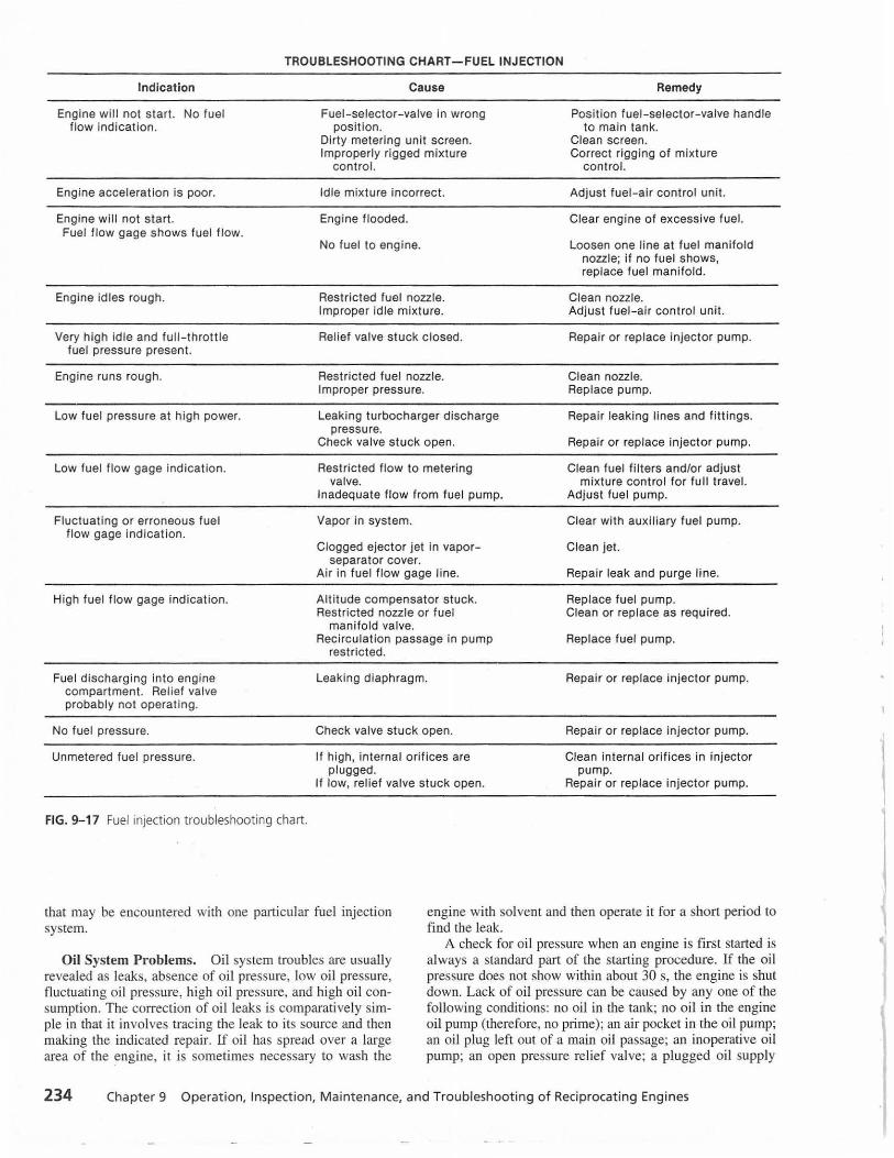
TROUBLESHOOTING CHART-FUEL INJECTION
Indication
Engine will not start. No fuel flow indicat ion.
Engine acceleration is poor.
Engine will not start. Fuel flow gage shows fuel flow.
Engine idles rough.
Very high idle and full-thrott le fuel pressure present.
Engine runs rough.
Low fuel pressure at high power.
Low fuel flow gage indicat ion.
Fluctuating or erroneous fuel flow gage indication.
High fuel flow gage indication.
Fuel discharging in to engine compartment. Relief valve probably not operating.
No fuel pressu re.
Unmetered fuel pressure.
FIG. 9-17 Fuel injection troubleshooting chart.
Cause
Fuel-selector-valve in wrong position.
Dirty metering unit screen. Improperly rigged mixture
control.
Idle mixture incorrect.
Engine flooded.
No fuel to engine.
Restricted fuel nozzle. Improper idle mixture.
Relief valve stuck closed.
Restricted fuel nozzle. Improper pressure.
Leaking turbocharger discharge pressure.
Check valve stuck o pen.
Restricted flow to metering valve.
Inadequate flow from fuel pump.
Vapor in system.
Clogged ejector jet in vaporseparator cover.
Air in fuel flow gage line.
Alti tude compensator stuck. Restricted nozzle or fuel
man ifold valve. Recirculation passage in pump
rest ricted.
Leaking diaphragm.
Check valve stuck open.
If high, internal orifices are plugged.
If low, reli ef valve stuck open.
Remedy
Posit ion fuel-selector-valve handle to main tank.
Clean screen. Correct rigging of mixture
control.
Adjust fuel-air control unit.
Clear eng ine of excessive fuel.
Loosen one line at fuel manifold nozzle; if no fuel shows, replace fuel manifold.
Clean nozzle. Adjust fuel -air control unit.
Repair or replace injector pump.
Clean nozzle. Replace pump.
Repair leaking lines and f ittings.
Repair or replace injector pump.
Clean fuel filters and/or adjust mixture control for full travel.
Adjust fuel pump.
Clear with auxil iary fuel pump.
Clean jet.
Repair leak and purge l ine.
Replace fuel pump. Clean or replace as required.
Replace fuel pump.
Repair or replace injector pump.
Repair or replace injector pump.
Clean internal orifices in injector pump.
Repair or replace injector pump.
that may be encountered with one particular fuel injection system.
engine with solvent and then operate it for a short period to find the leak.
Oil System Problems. Oil system troubles are usually revealed as leaks, absence of oil pressure, low oil pressure, fluctuating oil pressure, high oil pressure, and high oil consumption. The correction of oil leaks is comparatively simple in that it involves tracing the leak to its source and then making the indicated repair. If oi l has spread over a large area of the engine, it is sometimes necessary to wash the
A check for oil pressure when an engine is first started is always a standard part of the starting procedure. If the oil pressure does not show within about 30 s, the engine is shut down. Lack of oil pressure can be caused by any one of the following conditions: no oil in the tank; no oil in the engine oi l pump (therefore, no prime); an air pocket in the oi l pump; an oil plug left out of a main oil passage; an inoperative oil pump; an open pressure relief valve; a plugged oil supply
234 Chapter 9 Operation, Inspection, Maintenance, and Troubleshooting of Reciprocating Engines
1
1

line; or a broken oil line. If there is no oi l pressure, the technician should start with the most likely cause and then check each possibility in turn until the trouble is located.
Low oil pressure can be caused by a variety of discrepancies including the following: oi l pressure relief valve improperly adjusted, broken oil relief valve spring, sticking pressure relief valve, plug left out of an oil passage, defec" tive gasket inside the engine, worn oil pressure pump, worn bearings and/or bushings, dirty oil strainer, excessive temperature, wrong grade of oil, and leaking oil dilution valve. The cause of low oil pressure is often more difficult to discover than the causes of some other oil problems; however, a systematic analysis of the problem by technicians will usually lead to a solution. One of the first questions technicians must ask is whether the condition developed gradually, or showed up suddenly. They should also check how many hours of operation the engine has had. Another most important consideration is the actual level of the oil pressure. If it is extremely low, technicians look for an "acute" condition, and if it is only slightly low, the cause will probably be different.
High oil pressure can result from only a few causes: an improper setting of the relief valve, a sticking relief valve, an improper grade of oil, low temperature of oil and engine, and a plugged oil passage. The cause can usually be located easily except in a newly overhauled engine where a relief valve passage may be blocked. Note that the oil pressure will be abnormally high when a cold engine is first started and is not yet warmed up.
High oil consumption is usually the result of wear or leaks. If blue oil smoke is emitted from the engine breather and exhaust, most likely the piston rings are worn, so that blowby occurs . In blowby , pressure built up in the crankcase causes the oil spray inside the crankcase to be blown out the breather. High breather pressures occur in some engines because of buildup of sludge in the breather tube; this may be detected by excessive leakage in the propeller shaft seal. Cleanness of the breather tube is usually checked at the 100-h inspection on engines where this may be a problem. The worn rings also allow oil to pass the piston and enter the combustion chamber, where it is burned. This, of course, produces blue smoke at the exhaust.
Another cause of high oil consumption is a worn master rod bearing in a radial engine; this permits too much oil to be sprayed from the bearing and into the cylinder bores. If the scavenger pump is defective, th e o il wi ll not be removed from the sump as rapidly as required, and this will also lead to excessive oil consumption.
Operating an engine at h igh power settings and high temperatures will increase the oil consumption. If an apparently normal engine is using more oil than it should, the pilot should be questioned regarding engine operation in flight. The pilot should observe the reading of the oil pressure gage frequently during operation. If the gage should begin to fluctuate, the flight should be terminated as soon as possible because there may be a low oil supply.
Induction System Problems. The designs of induction systems for reciprocating engines vary considerably for different ai rcraft-and-engine combinations. The simplest types of induction systems include an air filter in the forward-facing air scoop, a carburetor air heating system, ducting to the carburetor, the carburetor, and an intake
manifold or intake pipes that carry the F/ A mixture to the valves. Other systems include turbochargers, superchargers, alternate air systems, and carburetor deicing systems. For a particular ai rcraft -engine combination, the technician should consult the operator's and maintenance manuals for the aircraft. Induction systems are described in Chap. 5.
These problems may arise in a typical induction system:
1. Dirty and/or damaged air filter 2. Worn, loose, or damaged air ducting 3. Loose or defective air temperature bulb 4. Defective air heater valve 5. Defective al ternate air valve 6. Loose carburetor mounting 7. Defective carburetor mounting gasket 8. Leaking packings or gaskets at intake pipes 9. Leaking intake manifold
Any crack or other opening that allows air to enter an intake manifold, in naturally aspirated engines, will cause the F/A m ixture to be excessively lean and may cause engine damage and adversely affect engine performance. Leaks in the intake manifold of a supercharged or turbocharged engine will allow the FIA mixture to escape, thus reducing MAP and engine power output.
Inspection of a typical induction system includes the following:
I. Check the ai r filter for condition, cleanness, and security. Service the air filter according to instructions.
2. Check the air ducting to the carburetor for wear damage, cracks, and security of mounting.
3. Check the air heater valve and ducting for wear, cracks, and security of mounting. Check the valve door bearings for wear, and lubricate according to instructions.
4. Check the CAT bulb for security. 5. Check the carburetor mounting for security. Tighten
any loose bolts or cap screws. 6. Check the carburetor mounting gasket for possible air
leakage. Replace the gasket if it is damaged. 7. Check the intake pipes and/or manifold for condition
and security. 8. Check the intake pipe packing nuts for tightness.
Check the packings or gaskets for shrinkage or damage. 9. Check the alternate air system for condition.
Backfiring. Backfiring occurs when the flame fro m the combustion chamber burns back into the intake mani fold and ignites the FIA mixture before the mixture enters the engine. It often occurs during starting of a cold engine because of poor (slow) combustion. The FIA mixture in the cylinder is still burning at the time the intake valve opens, and the flame burns back through the intake valve. This sometimes causes a fire in the induction system.
Any defect in the carburetor or fuel control syste m which causes an excessively lean mixture can lead to backfiring. If the condition persists after an engine is warmed up, follow a systematic procedure to locate the cause.
Another cause of backfiring is sticking intake valves. This does not usually occur with a new or recently overhauled engine, but it is likely to be encountered with an older engine operated at high temperatures. If a sticking intake valve remains open, it can cause the engine to stop
Troubleshooting 235

and may cause considerable damage to the induction system.
Ignition troubles often cause backfiring. If high-tension current leaks at the distributor block, it can cause the plugs to fire out of time, so that the mixture may fire in a cylinder when the intake valve is open. If a newly overhauled engine is being staited for the first time and backfiring persists, the technician should check for ignition timing and for proper connection of the spark plug leads. Ignition out of time can also cause afterfiring through the exhaust.
Afterfiring. Afterfiring is the burning of Fl A mixture in the exhaust mani fold after the mixture has passed through the exhaust valve. It is characterized by explosive sounds and lai·ge flames trailing outward from the exhaust stacks (torching). Usually excessive fuel (rich mixture) in the exhaust continues to bum after the mixture leaves the cylinder. The condit ion may be caused by overpriming, excessively rich mixture, poor ignition, and improper timing. Since there are comparatively few causes of afterfiring, it is usually easy to correct.
REVIEW QUESTIONS
1. If a fire occurs during starting of the engine, what should the operator do?
2. What fire extinguishing agent is commonly used on a reciprocating engine fire?
3. When starting an engine with a float-type carburetor, where should the mixture control be positioned?
4. What is meant by the term "liquid lock"?
5. What should be done if there is no indication of oil pressure shortly after starting the engine?
6. In the operation of an engine with a constantspeed propeller, what sequences should be followed in changing power settings?
7. What is meant by "cruise control"? 8. How is maximum range obtained in the opera
tion of an aircraft engine? 9. When an engine is equipped with a carburetor
which has an idle cutoff, what is the procedure for shutting down the engine?
10. Why is the mixture leaned out on a reciprocating engine?
11. What is the general procedure for leaning out the mixture on an engine equipped with a float-type carburetor?
12. What operating procedures can help reduce lead fouling of the spark plugs?
13. What is meant by preheating an engine? 14. What should be used to clean an aircraft engine? 15. What inspection should be made with respect to
the engine when an oil screen is serviced? 16. How is an oil filter inspected when it is removed
from an engine during inspection? 17. Name two types of compression testers utilized
on reciprocating engines. 18. When using a different ial-pressure compression
tester, what percentage pressure loss is considered unacceptable?
19. What are the procedures for servicing a drypaper induction air filter?
20. List the six steps that should be utilized in troubleshooting an engine.
236 Chapter 9 Operation, Inspection, Maintenance, and Troubleshooting of Reciprocating Engines