1500r maintenance and troubleshooting
DESCRIPTION
1500 R maintenance and troubleshottingTRANSCRIPT
1
Maintenance and Troubleshooting
2
Module consists of presentation
Module covers the Maintenance Procedures
Documents
Training book
Yearly maintenance procedure
Software upgrade procedure
Unit replacement procedure
Module Overview
3
On successful completion of this module the participants would be able to:
Perform yearly check
Upgrade software via CeraView
Replace faulty cards
Learning Objectives
4
1. Yearly check procedure
2. Software upgrade procedure
3. Replace unit procedure
Module Topics
5
On successful completion of this module the participants would be able to:
Understand the LED’s colors
Analyze faults
Use diagnostic tools
Monitor link performance
Learning Objectives
6
1. Front panel LEDs
2. Troubleshooting
3. Performance
4. Loopbacks
Module Topics
7
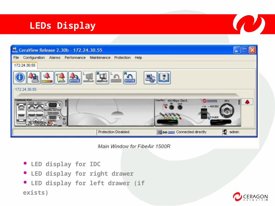
LEDs Display
LED display for IDC LED display for right drawer LED display for left drawer (if exists)
8
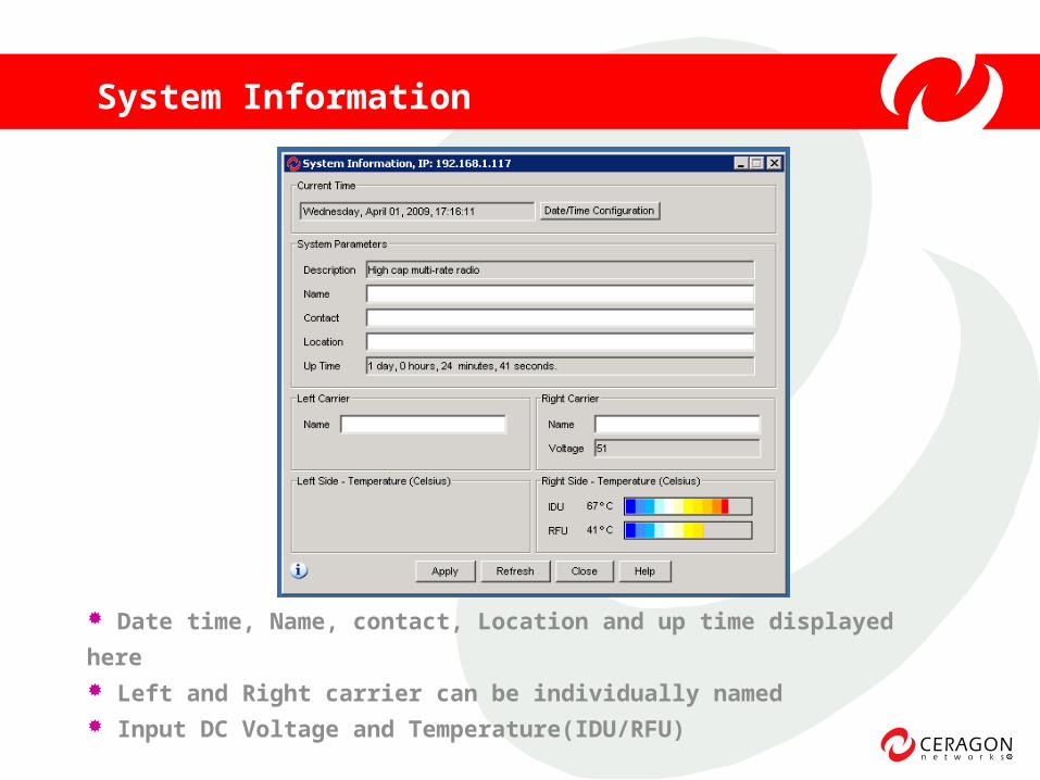
Date time, Name, contact, Location and up time displayed here Left and Right carrier can be individually named Input DC Voltage and Temperature(IDU/RFU)
System Information
9
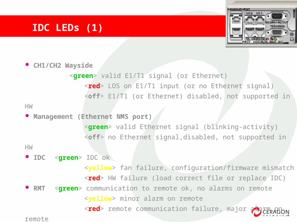
IDC LEDs (1)
CH1/CH2 Wayside
<green> valid E1/T1 signal (or Ethernet)
<red> LOS on E1/T1 input (or no Ethernet signal)
<off> E1/T1 (or Ethernet) disabled, not supported in HW Management (Ethernet NMS port)
<green> valid Ethernet signal (blinking-activity)
<off> no Ethernet signal,disabled, not supported in HW IDC <green> IDC ok
<yellow> fan failure, configuration/firmware mismatch
<red> HW failure (load correct file or replace IDC) RMT <green> communication to remote ok, no alarms on remote
<yellow> minor alarm on remote
<red> remote communication failure, major alarm on remote
10
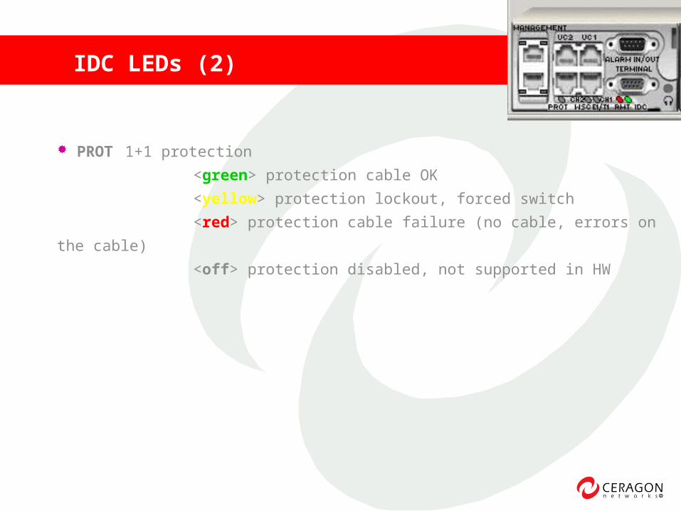
IDC LEDs (2)
PROT 1+1 protection
<green> protection cable OK
<yellow> protection lockout, forced switch
<red> protection cable failure (no cable, errors on the cable)
<off> protection disabled, not supported in HW
11
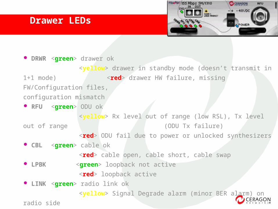
Drawer LEDs .
DRWR <green> drawer ok
<yellow> drawer in standby mode (doesn’t transmit in 1+1
mode) <red> drawer HW failure, missing FW/Configuration files,
configuration mismatch RFU <green> ODU ok
<yellow> Rx level out of range (low RSL), Tx level out of range
(ODU Tx failure)
<red> ODU fail due to power or unlocked synthesizers CBL <green> cable ok
<red> cable open, cable short, cable swap LPBK <green> loopback not active
<red> loopback active LINK <green> radio link ok
<yellow> Signal Degrade alarm (minor BER alarm) on radio
side
<red> Loss Of Frame, EXC alarm (major BER alarm) on radio
side
12
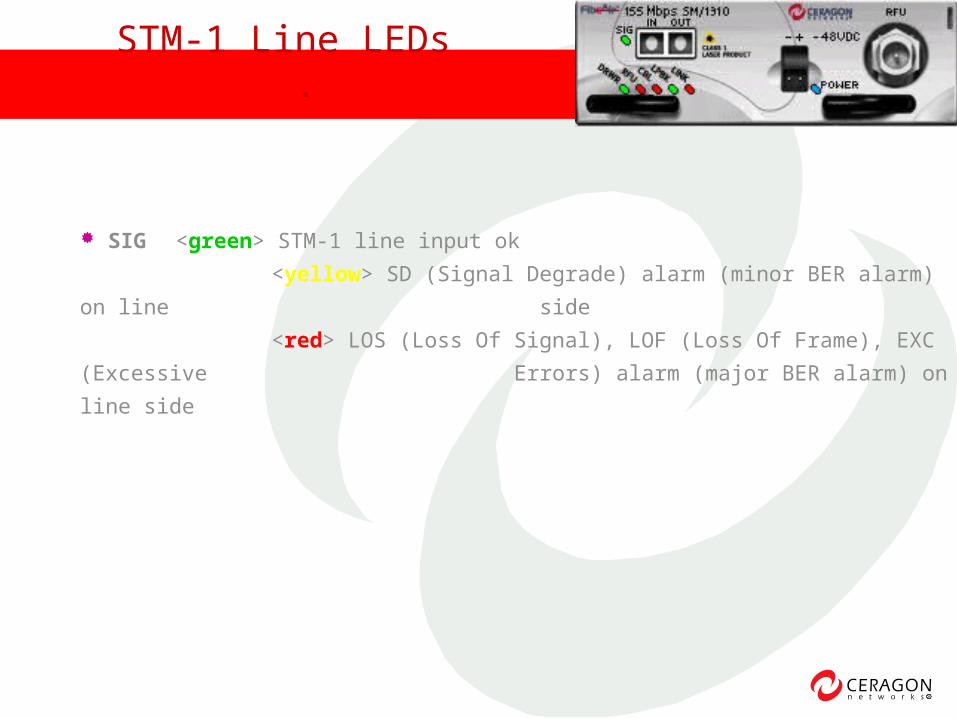
SIG <green> STM-1 line input ok
<yellow> SD (Signal Degrade) alarm (minor BER alarm) on line
side
<red> LOS (Loss Of Signal), LOF (Loss Of Frame), EXC
(Excessive Errors) alarm (major BER alarm) on line
side
STM-1 Line LEDs .
13
Alarm log
Configuration report
Receive Signal Level PM
Radio SDH PM
STM-1 Line SDH PM
Loop backs
Troubleshooting Tools
14
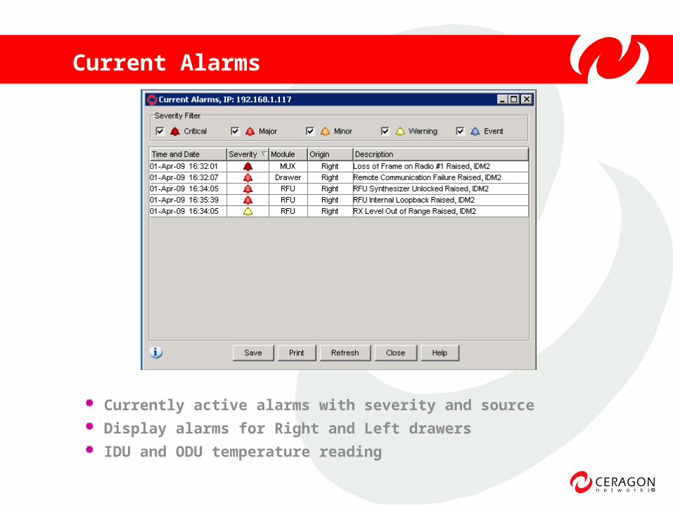
Current Alarms
Currently active alarms with severity and source Display alarms for Right and Left drawers IDU and ODU temperature reading
15
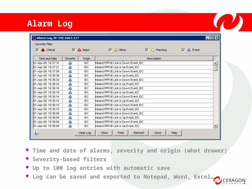
Alarm Log
Time and date of alarms, severity and origin (what drawer) Severity-based filters Up to 100 log entries with automatic save Log can be saved and exported to Notepad, Word, Excel…
16
Troubleshooting Using Alarm Log
Check current alarm (!!!)
Identify when alarms started
Identify separate events based on time
Check correlation with other links failed
Check correlation to RSL to explain alarms
Check correlation to Radio/Line SDH PM
17
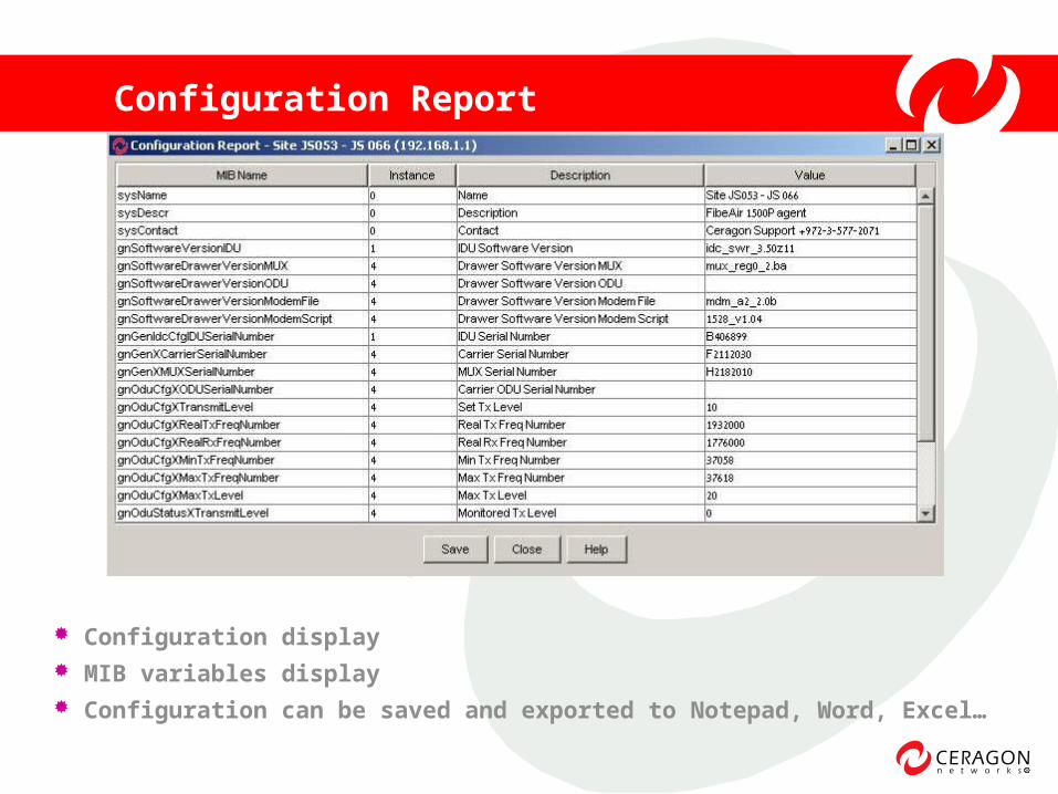
Configuration Report
Configuration display MIB variables display Configuration can be saved and exported to Notepad, Word, Excel…
18
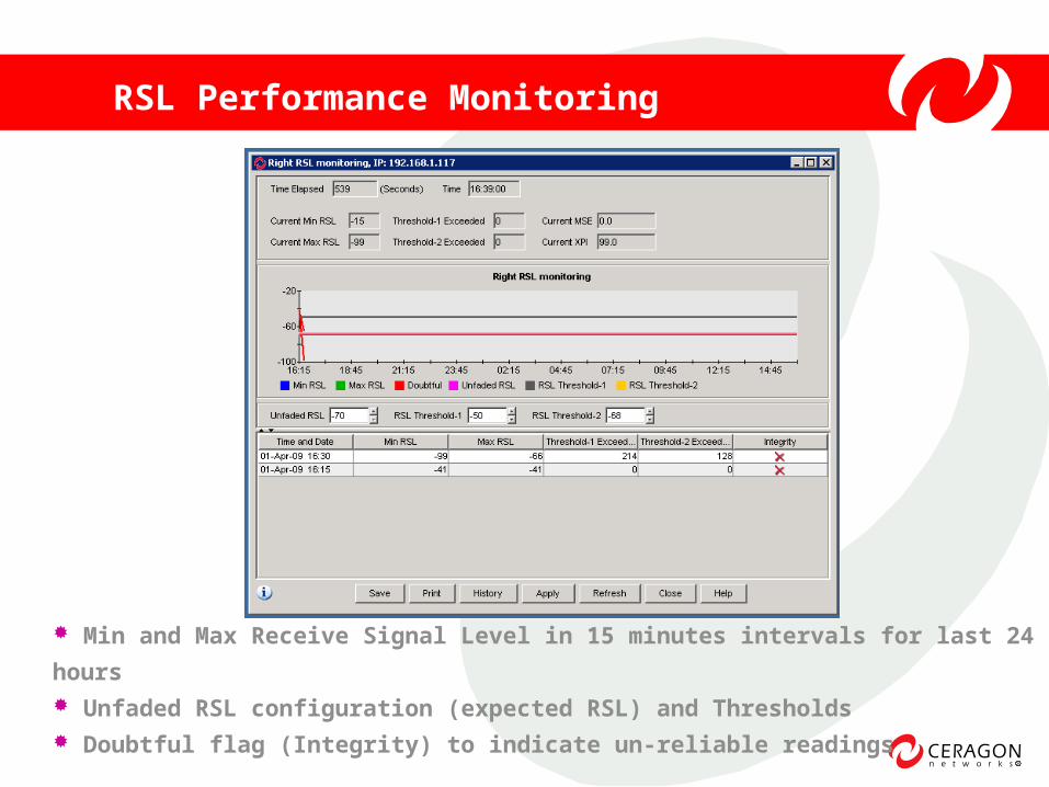
RSL Performance Monitoring
Min and Max Receive Signal Level in 15 minutes intervals for last 24
hours Unfaded RSL configuration (expected RSL) and Thresholds Doubtful flag (Integrity) to indicate un-reliable readings

19
RSL – Multipath Example
20
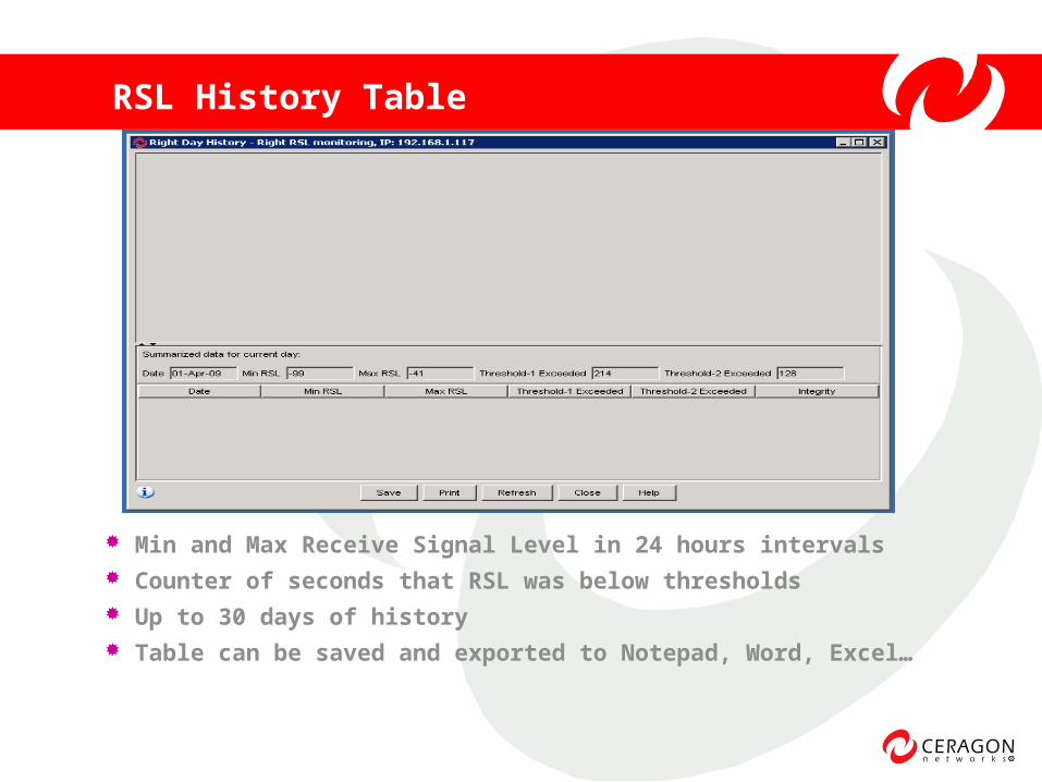
RSL History Table
Min and Max Receive Signal Level in 24 hours intervals Counter of seconds that RSL was below thresholds Up to 30 days of history Table can be saved and exported to Notepad, Word, Excel…
21
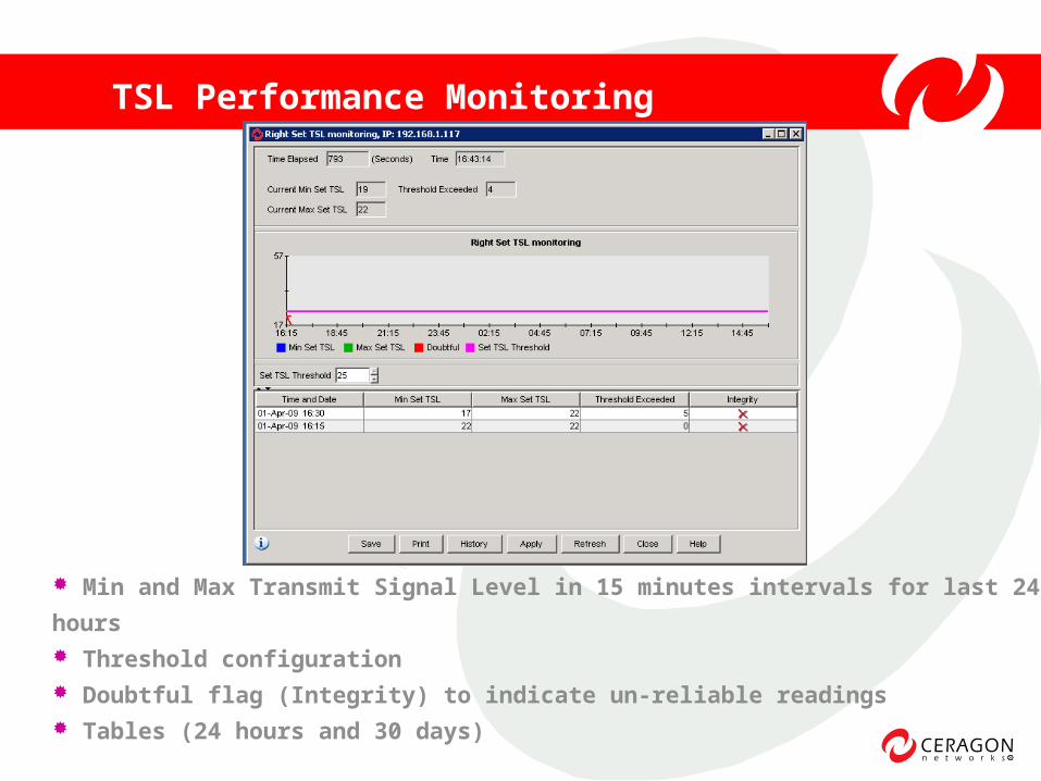
TSL Performance Monitoring
Min and Max Transmit Signal Level in 15 minutes intervals for last 24
hours Threshold configuration Doubtful flag (Integrity) to indicate un-reliable readings Tables (24 hours and 30 days)
22
Check current RSL
Check changes in RSL during last 24hours (5dB change
during the day is normal)
Identify rain fading, multi-path
Check if RSL reached sensitivity threshold
In case of ATPC, check Transmit Signal Level
Troubleshooting Using RSL PM
23
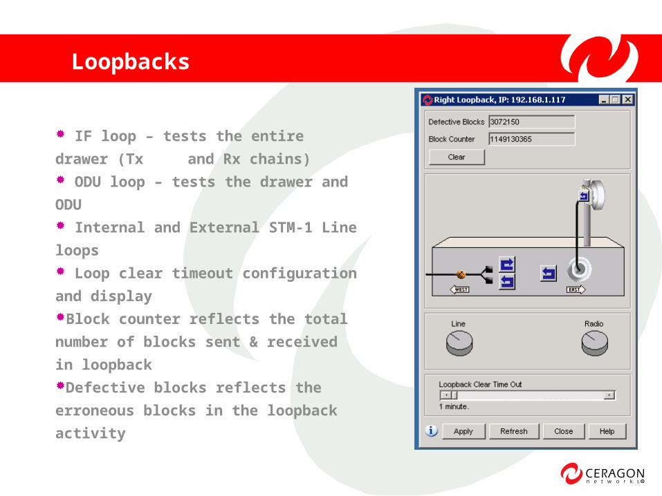
Loopbacks
IF loop – tests the entire drawer
(Tx and Rx chains) ODU loop – tests the drawer and
ODU Internal and External STM-1 Line
loops Loop clear timeout configuration
and displayBlock counter reflects the total
number of blocks sent & received in
loopbackDefective blocks reflects the
erroneous blocks in the loopback
activity
24
If problem currently exists:
Use Line loop in case of LOS, LOF or Errors on STM-1 input of
IDU or external ADM
Use IF loop in case of LOF or BER to identify if IDU is OK
Use ODU loop in case of LOF or BER if IF loop passed OK
Troubleshooting Using Loopbacks