operation and installation - gdc · operation and installation datacomm 500f/s. ... avoir recours...
TRANSCRIPT
General DataComm048R216-000 Issue 1
Operation and Installation
DataComm 500F/S

Operation and Installation
DataComm 500F/S
Warning
This equipment generates, uses, and can radiate radio frequency energy and if not installed and used inaccordance with the instruction manual, may cause interference to radio communications. It has been testedand found to comply with the limits for a Class A computing device pursuant to CISPR 22, which is designedto provide reasonable protection against such interference when operated in a commercial environment.Operation of this equipment in a residential area is likely to cause interference, in which case the user at hisown expense will be required to take whatever measures may be required to correct the interference. The user iscautioned that any changes or modifications not expressly approved by General DataComm void the user’sauthority to operate the equipment.
This digital apparatus does not exceed Class A limits for radio noise emissions from digital apparatusdescribed in the Radio Interference Regulations of the Canadian Department of Communications.
Le présent appareil numérique n’émet pas de bruits radioélectriques dépassant les limites applicables auxappareils numériques de la classe A prescrites dans le Règlement sur le brouillage radioélectrique édicté par leministère des Communications du Canada.
Warranty
General DataComm warrants that its equipment is free from defects in materials and workmanship. Thewarranty period is one year from the date of shipment. GDC's sole obligation under its warranty is limited tothe repair or replacement of the defective equipment provided it is returned to GDC, transportation prepaid,within a reasonable period. This warranty will not extend to equipment subjected to accident, misuse, oralterations or repair not made by GDC or authorized by GDC in writing. The foregoing warranty is exclusiveand in lieu of all other warranties, express or implied, including but not limited to, warranties ofmerchantability and fitness for purpose.
Trademarks and Patents
General DataComm, the General DataComm logo and the following are trademarks of General DataComm, Incin the United States and other countries: ACCULINE, ANALOOP, AUTOFRAME, BERT 901, DATACOMMSECURE-PAK, DATALOOP, DIGIDIAL, ENmacs, FASTPRO, FIRST RESPONSE, GDC, GDC APEX, GENERALDATACOMM X-PRESS, GEN*NET, GEN*PAC, IMAGE*TMS, KILOMUX, LAN*TMS, MEGA*BRIDGE,MEGAMUX, MEGAMUX TMS, MEGANET, MEGASPLIT, MEGASWITCH, MEGAVIEW, NETCON,NETSWITCH, NMC, QUIKSHIPPERS, SERVI-CHECK, SERVI-SNAP, WINmacs.
The product(s) referenced in this publication may be covered by one or more of the following U.S. patents:4,095,045; 4,841,561; 5,048,056; 5,265,151; 5,291,520; 5,260,971. Licensed under U.S. patent4,558,302. Foreign and additional U.S. patent applications may be pending.
GDC products are covered under the following patents:
4,122,309 4,290,139 4,394,767 4,412,141 4,412,350 4,437,182 4,437,183 4,450,558 4,460,9934,471,489 4,667,180 4,689,607 4,691,190 4,692,639 4,694,450 4,717,216 4,727,536 4,729,1234,710,920 4,745,395 4,783,034 4,803,654 4,809,300 4,811,360 4,815,074 4,817,147 4,827,4314,839,542 4,845,735 4,856,031 4,858,163 4,877,364 4,881,224 4,885,745 4,888,722 4,888,7704,891,754 4,891,823 4,922,534 4,926,355 4,930,125 4,961,138 4,966,556 5,113,412 5,146,4725,157,651 5.160,270 5,215,471 5,256,073 5,317,594 5,331,672 5,348,484 5,366,380 re27,864
All other products or services mentioned in this document are identified by the trademarks, service marks, orproduct names as designated by the companies who market those products. Inquiries concerning suchtrademarks should be made directly to those companies.
Copyright
© 1995 General DataComm, Inc. All rights reserved.P.O. Box 1299, Middlebury, Connecticut 06762-1299 U.S.A.
This publication and the software it describes contain proprietary and confidential information. No part ofthis document may be copied, photocopied, reproduced, translated or reduced to any electronic or machine-readable format without prior written permission of General DataComm, Inc.
The information in this document is subject to change without notice. General DataComm assumes noresponsibility for any damages arising from the use of this document, including but not limited to, lostrevenue, lost data, claims by third parties, or other damages. If you have comments or suggestionsconcerning this manual, please write to Technical Publications or call 1-203-758-1811.
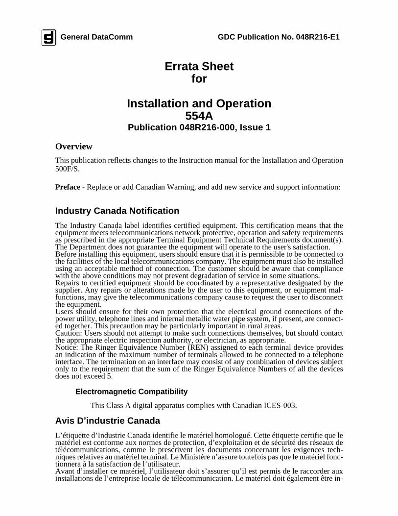
Errata Sheetfor
Installation and Operation554A
Publication 048R216-000, Issue 1
Overview
This publication reflects changes to the Instruction manual for the Installation and Operation500F/S.
Preface - Replace or add Canadian Warning, and add new service and support information:
Industry Canada Notification
The Industry Canada label identifies certified equipment. This certification means that theequipment meets telecommunications network protective, operation and safety requirementsas prescribed in the appropriate Terminal Equipment Technical Requirements document(s).The Department does not guarantee the equipment will operate to the user's satisfaction.Before installing this equipment, users should ensure that it is permissible to be connected tothe facilities of the local telecommunications company. The equipment must also be installedusing an acceptable method of connection. The customer should be aware that compliancewith the above conditions may not prevent degradation of service in some situations.Repairs to certified equipment should be coordinated by a representative designated by thesupplier. Any repairs or alterations made by the user to this equipment, or equipment mal-functions, may give the telecommunications company cause to request the user to disconnectthe equipment.Users should ensure for their own protection that the electrical ground connections of thepower utility, telephone lines and internal metallic water pipe system, if present, are connect-ed together. This precaution may be particularly important in rural areas.Caution: Users should not attempt to make such connections themselves, but should contactthe appropriate electric inspection authority, or electrician, as appropriate.Notice: The Ringer Equivalence Number (REN) assigned to each terminal device providesan indication of the maximum number of terminals allowed to be connected to a telephoneinterface. The termination on an interface may consist of any combination of devices subjectonly to the requirement that the sum of the Ringer Equivalence Numbers of all the devicesdoes not exceed 5.
Electromagnetic Compatibility
This Class A digital apparatus complies with Canadian ICES-003.
Avis D’industrie Canada
L’étiquette d’Industrie Canada identifie le matériel homologué. Cette étiquette certifie que lematériel est conforme aux normes de protection, d’exploitation et de sécurité des réseaux detélécommunications, comme le prescrivent les documents concernant les exigences tech-niques relatives au matériel terminal. Le Ministère n’assure toutefois pas que le matériel fonc-tionnera à la satisfaction de l’utilisateur.Avant d’installer ce matériel, l’utilisateur doit s’assurer qu’il est permis de le raccorder auxinstallations de l’entreprise locale de télécommunication. Le matériel doit également être in-
General DataComm GDC Publication No. 048R216-E1
stallé en suivant une méthode acceptée de raccordement. L’abonné ne doit pas oublier qu’il estpossible que la comformité aux conditions énoncées ci-dessus n’empêche pas la dégradationdu service dans certaines situations.Les réparations de matériel homologué doivent être coordonnées par un représentant désignépar le fournisseur. L’entreprise de télécommunications peut demander à l’utilisateur dedébrancher un appareil à la suite de réparations ou de modifications effectuées par l’utilisateurou à cause de mauvais fonctionnement.Pour sa propre protection, l’utilisateur doit s’assurer que tous les fils de mise à la terre de lasource d’énergie électrique, des lignes téléphoniques et des canalisations d’eau métalliques, s’ily en a, sont raccordés ensemble. Cette précaution est particulièrement importante dans les ré-gions rurales.Avertissement: L’utilisateur ne doit pas tenter de faire ces raccordements lui-même; il doitavoir recours à un service d’inspection des installations électriques, ou à un électricien, selonle cas.Avis: L’indice d’équivalence de la sonnerie (IES) assigné à chaque dispositif terminal indiquele nombre maximal de terminaux qui peuvent être raccordés à une interface. La terminaisond’une interface téléphonique peut consister en une combinaison de quelques dispositifs, à laseule condition que la somme d’indices d’équivalence de la sonnerie de tous les dispositifsn’excède pas 5.
La Compatibilité d’ Eléctro-magnetique
Cet appareil numerique de la classe A est conforme a la norme NMB-003 du Canada.
Service Support and TrainingVITAL Network Services, a General DataComm company, is committed to providing the service support and training needed to install, manage, and maintain your GDC equipment.GDC’s VITAL Network Services provides hands-on training courses through VITAL Net-work Services Global Technology Training Services. Courses range from basic data com-munications, modems and multiplexers, to complex network and ATM systems. Training courses are available at our centers in the US, UK, France, Singapore and Mexico, as well as at a customer’s site.For more information regarding GDC's VITAL Network Services’ service programs, training courses, or for assistance with your support requirements, contact GDC's VITAL Network Services at the address or phone number listed below, or visit our website at: http//www.vital-netsvc.com
VITAL Network Services World Headquarters6 Rubber AvenueNaugatuck, Connecticut 06770 USA
North America:1 800 243 10301 888 248 48251 203 729 2461Training Information:1 203 729 0271French Speaking Canada:1 800 361 2552North America Fax:1 203 723 50121 203 729 7611
July 1998
VITAL Network Services Regional Sales and Service Offices:
Europe, Middle East, AfricaVITAL Network ServicesMolly Millars CloseMolly Millars LaneWokingham, Berkshire RG41 2QF UK
Telephone: +44 1189 657200Training: +44 1189 657240Fax: +44 1189 657279
Central America, Latin AmericaVITAL Network ServicesPeriferico Sur 4225, Desp. 306C.P. 14210, Mexico D.F., Mexico
Telephone: +52 5 645 2238Training: +52 5 645 2238Fax: +52 5 645 5976
Asia PacificVITAL Network Services501 Orchard Road 05-05Wheelock Place, Singapore 238880
Telephone: +65 735 2123Training: +65 735 2123Fax: +65 735 6889
International Calling Code (+)When calling from outside the country of origin, use the appropriate International Calling Code where the + symbol is shown.
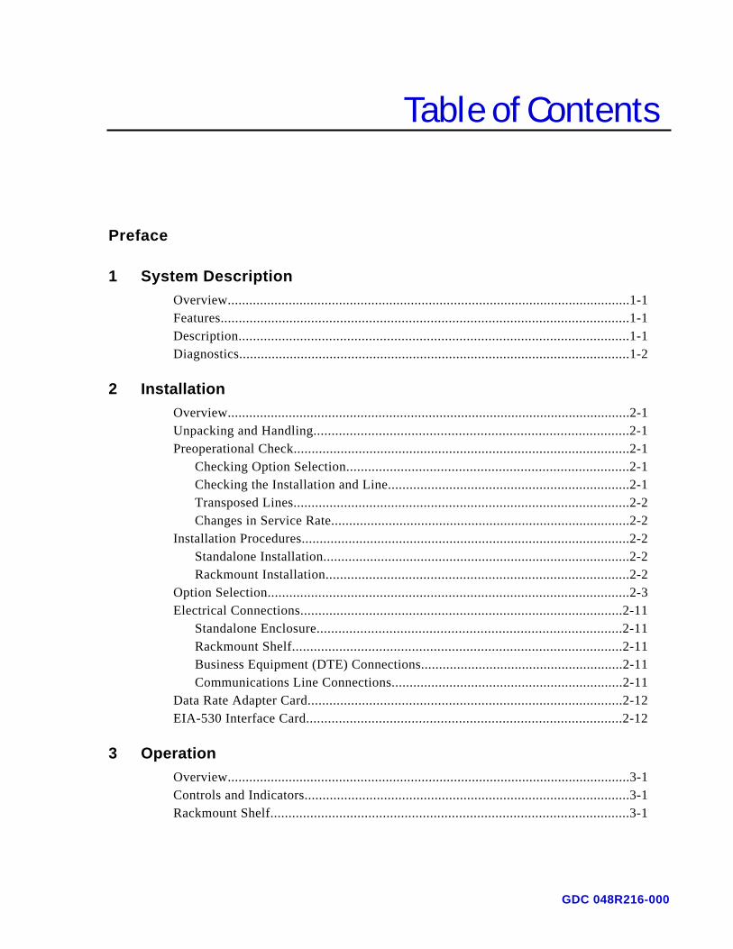
Table of Contents
Preface
1 System DescriptionOverview................................................................................................................1-1Features.................................................................................................................1-1Description............................................................................................................1-1Diagnostics............................................................................................................1-2
2 InstallationOverview................................................................................................................2-1Unpacking and Handling.......................................................................................2-1Preoperational Check.............................................................................................2-1
Checking Option Selection..............................................................................2-1Checking the Installation and Line...................................................................2-1Transposed Lines.............................................................................................2-2Changes in Service Rate...................................................................................2-2
Installation Procedures...........................................................................................2-2Standalone Installation.....................................................................................2-2Rackmount Installation....................................................................................2-2
Option Selection....................................................................................................2-3Electrical Connections.........................................................................................2-11
Standalone Enclosure....................................................................................2-11Rackmount Shelf...........................................................................................2-11Business Equipment (DTE) Connections........................................................2-11Communications Line Connections................................................................2-11
Data Rate Adapter Card.......................................................................................2-12EIA-530 Interface Card.......................................................................................2-12
3 OperationOverview................................................................................................................3-1Controls and Indicators..........................................................................................3-1Rackmount Shelf...................................................................................................3-1
GDC 048R216-000
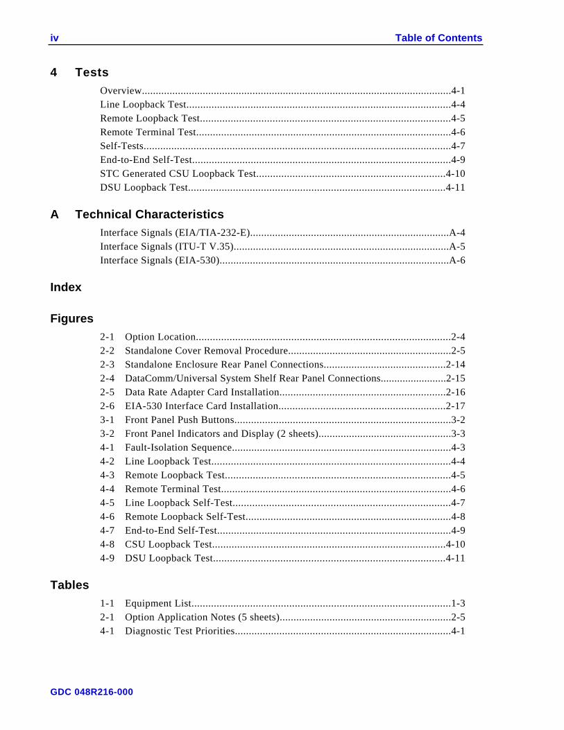
iv Table of Contents
4 TestsOverview................................................................................................................4-1Line Loopback Test...............................................................................................4-4Remote Loopback Test..........................................................................................4-5Remote Terminal Test............................................................................................4-6Self-Tests...............................................................................................................4-7End-to-End Self-Test.............................................................................................4-9STC Generated CSU Loopback Test....................................................................4-10DSU Loopback Test............................................................................................4-11
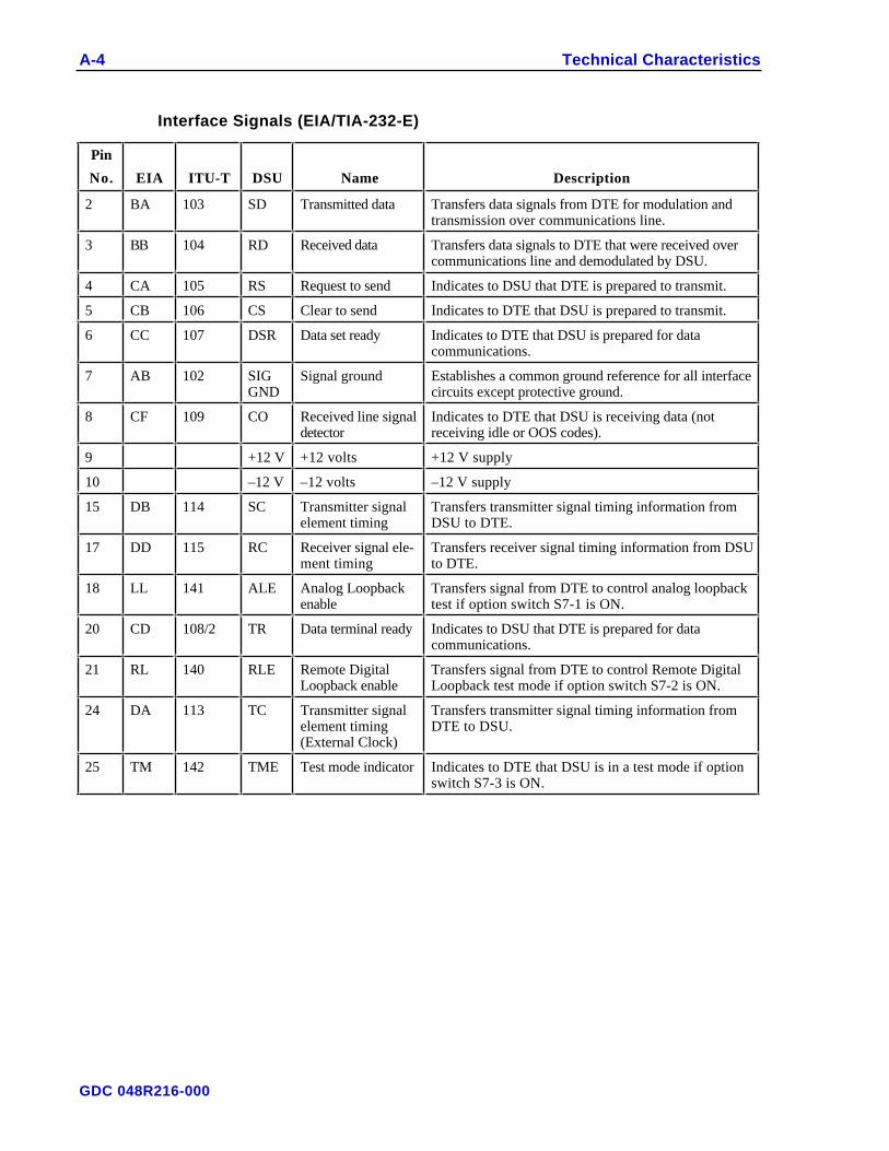
A Technical CharacteristicsInterface Signals (EIA/TIA-232-E)........................................................................A-4Interface Signals (ITU-T V.35)..............................................................................A-5Interface Signals (EIA-530)...................................................................................A-6
Index
Figures2-1 Option Location...........................................................................................2-42-2 Standalone Cover Removal Procedure...........................................................2-52-3 Standalone Enclosure Rear Panel Connections............................................2-142-4 DataComm/Universal System Shelf Rear Panel Connections........................2-152-5 Data Rate Adapter Card Installation............................................................2-162-6 EIA-530 Interface Card Installation............................................................2-173-1 Front Panel Push Buttons..............................................................................3-23-2 Front Panel Indicators and Display (2 sheets)................................................3-34-1 Fault-Isolation Sequence...............................................................................4-34-2 Line Loopback Test......................................................................................4-44-3 Remote Loopback Test.................................................................................4-54-4 Remote Terminal Test...................................................................................4-64-5 Line Loopback Self-Test..............................................................................4-74-6 Remote Loopback Self-Test..........................................................................4-84-7 End-to-End Self-Test....................................................................................4-94-8 CSU Loopback Test....................................................................................4-104-9 DSU Loopback Test...................................................................................4-11
Tables1-1 Equipment List.............................................................................................1-32-1 Option Application Notes (5 sheets)..............................................................2-54-1 Diagnostic Test Priorities..............................................................................4-1
GDC 048R216-000
Preface
ScopeThis manual describes how to install and configure a General DataComm 500F/S. Itexplains how to monitor and manage this device. It is written for operators and installersand assumes a working knowledge of data communications.
OrganizationThis manual has four chapters and one appendix.
• Chapter 1 - Introduction introduces important concepts and features of theDataComm 500F/S.
• Chapter 2 - Installation tells you how to install the DataComm 500F/S. Onlytypical or fundamental applications are given because of the variety of specificcustomer system choices.
• Chapter 3 - Operation describes the front panels, and the use of the managedoptions.
• Chapter 4 - Tests describes front panel and managed tests.
• APPENDIX A describes the technical characteristics of the unit.
• INDEX contains the DataComm 500F/S subject and page number.
Document Conventions
Level 1 paragraph headers introduce major topics.
Level 2 paragraph headers introduce subchapters of major topics.
Level 3 paragraph headers introduce subchapters of secondary topics.
NOTENotes present special instructions, helpful hints or general rules..
Related PublicationsThe following documents have additional information that may be helpful when usingthis product:
• Operating and Installation Instructions forDataComm Shelf GDC 010R310-000
GDC 048R216-000
vi Preface
• Operating and Installation Instructions forUniversal System Shelf GDC 010R380-000
GDC publication numbers (e.g., GDC 048R216-000) are used to track and ordertechnical manuals. Publication numbers use the following format:
GDC NNNRnnn-000 or GDC NNNRnnn-Vnnn
NNN identifies the product family (e.g. DataComm)
R denotes a technical publication
nnn a number assigned by Technical Publications
000 identifies a hardware product and does not change
Vnnn the software version associated with a product may be updated periodically
The Issue Number on the title page only changes when a hardware manual is revised orwhen a manual is reprinted for some other reason.
Service and SupportGeneral DataComm is committed to providing the service and support needed to install,manage, and maintain your equipment. For information about service programs or forassistance with your support requirements, contact your local Sales Representative or callDataComm Service Corporation (DSC) at the 24-hour toll free number listed below.
• in the U.S. dial 1-800-243-1030
• outside the U.S. dial 1-203-598-7526
Be ready with the site name and phone number and a description of the problem and thenext available support representative will promptly return your call.
Hands-on training courses are provided by DSC Educational Services. Courses rangefrom basic data communications, modems and multiplexers, to complex network andATM systems and are taught in Connecticut or at a customer location. Call 1-800-242-1030 and follow the menu instructions to discuss educational services or to receive acourse schedule.
GDC 048R216-000
Preface vii
Safety Instructions
Antistatic PrecautionsElectrostatic discharge (ESD) results from the buildup of static electricity and can causecomputer components to fail. Electrostatic discharge occurs when a person whose bodycontains a static buildup touches a computer component.
The equipment may contain static-sensitive devices that are easily damaged and properhandling and grounding is essential. Use ESD precautionary measures when installingparts or cards and keep the parts and cards in antistatic packaging when not in use. Ifpossible, use antistatic floorpads and workbench pads.
When handling components, or when setting switch options, always use an antistatic wriststrap connected to a grounded equipment frame or chassis. If a wrist strap is notavailable, periodically touch an unpainted metal surface on the equipment. Never use aconductive tool, such as a screwdriver or a paper clip, to set switches.
Safety GuidelinesThe following symbols are used when unsafe conditions exist or when potentiallyhazardous voltages are present:
Caution statements identify conditions or practices that can result indamage to the equipment or in loss of data.
Warning statements identify conditions or practices that can result inpersonal injury or loss of life.
Always use caution and common sense. To reduce the risk of electrical shock, do notoperate any equipment with the cover removed. Repairs must be performed by qualifiedservice personnel only.
• Never install telephone jacks in a wet location unless the jack is designed for thatlocation.
• Never touch uninsulated telephone wires or terminals unless the telephone line isdisconnected at the network interface.
• Use caution when installing telephone lines and never install telephone wiringduring an electrical storm.
GDC 048R216-000
viii Preface
Regulatory Notices
FCC Part 68 ComplianceConnection of data communications equipment to the public telephone network isregulated by FCC Rules and Regulations. This equipment complies with Part 68 of theseregulations which require all of the following:
All connections to the telephone network must be made using standard plugs andtelephone company provided jacks or equivalent. Connection of this equipment to partylines and coin telephones is prohibited. A label on the back of the front panel of datacommunications equipment and on the underside or rear panel of other equipmentprovides the FCC Registration number and the Ringer Equivalence Number (REN) for theunit. If requested, give this information to the telephone company.
If the unit causes harm to the telephone network, the telephone company may discontinueyour service temporarily and if possible, you will be notified in advance. If advancenotice is not practical, you will be notified as soon as possible and will be advised of yourright to file a complaint with the FCC. The telephone company may change itscommunication facilities, equipment, operations and procedures where reasonablyrequired for operation. If so, the telephone company will notify you in writing. Youmust notify the telephone company before disconnecting equipment from 1.544 Mbpsdigital service. All repairs or modifications to the equipment must be performed byGeneral DataComm. Any other repair or modification by a user voids the FCCregistration and the warranty.
Canada DOC NotificationThe Canadian Department of Communications label identifies certified equipment. Thiscertification means that the equipment meets certain telecommunications networkprotective, operational, and safety requirements. The Department does not guarantee theequipment will operate to the user's satisfaction.
Before installing this equipment, users should ensure that it is permissible to be connectedto the facilities of the local telecommunications company. The equipment must also beinstalled using an acceptable method of connection. In some cases, the company's insidewiring associated with a single line individual service may be extended by means of acertified connector assembly (telephone extension cord). The customer should be awarethat compliance with the above conditions may not prevent degradation of service insome situations.
Repairs to certified equipment should be made by an authorized Canadian maintenancefacility designated by the supplier. Any repairs or alterations made by the user to thisequipment, or equipment malfunctions, may give the telecommunications company causeto request the user to disconnect the equipment.
Users should ensure for their own protection that the electrical ground connections of thepower utility, telephone lines, and internal metallic water pipe system, if present, areconnected together. This precaution may be particularly important in rural areas. Usersshould not attempt to make such connections themselves, but should contact theappropriate electric inspection authority, or electrician, as appropriate.
GDC 048R216-000

Preface ix
Bundesrepublik DeutschlandInstallieren Sie nie die Telefonleitungen wahrend eines Gewitters. Installieren Sie nie dieTelefonbuchsen in einem feuchten Raum es sei denn die Buchs ist spezielle fürFeuchträume vorgeshen. Berühren sie nie unisoliete Telefonleitungen oderEinrichtungen es sei denn die Leitungen sind vom Telefonnetz getrennt. Vorsicht bei derInstallierung oder Änderung von Telefonleitungen. Achtung: Es sind keine durch dennAnwender zu wartende Teils im Gerät. Warting darf nur durch qualifizietes Personalerfolgen. Vor Wartung vom Stromnetz trennen.
Glossary of Terms
Asynchronous TransmissionSerial transmission of data in which each character is individually synchronized by theuse of start and stop bits. A start bit precedes and one or more stop bits follow continuousinformation bits. Also called start-stop transmission. There is no definite time relationshipbetween transmission of successive characters.
Auto-RateAutomatic data rate selection. The DSU automatically selects the data rate for transparentservice upgrades between subrates, as well as for upgrades from subrate to high speed(56/64 kbps) operation, by adjusting its rate to match that of the incoming network signal.The DSU continually attempts to Auto-Rate on power-up or when the line signal wasabsent for longer than 10 seconds and recovered.
Bit Error Rate (BER)The percentage of received bits that are in error, relative to a specific amount of bitsreceived; usually expressed as a number referenced to a power of 10; e.g., 1 in 105.
ChannelPart of a circuit path through several entities in a communication system. A channel runsbetween two nodes.
Channel Service Unit (CSU)A component of customer premises equipment (CPE) used to terminate a digital circuit,such as DDS or T1, at the customer site; performs certain line-conditioning features,ensures network compliance per FCC rules, and responds to loopback commands fromcentral office; also, ensures proper ones density in transmitted bit stream and performsbipolar violation correction.
Data Communications Equipment (DCE)Equipment that provides the signal conversion, connection control, and coding requiredfor communication between data terminal equipment and data circuits; may beindependent (e.g., a modem) or an integral part of a computer.
DataphoneA service and trademark of AT&T; generically refers to the transmission of data over thephone network (Dataphone Digital Service, or DDS), or to equipment furnished by thetelephone company for data transmission
GDC 048R216-000
x Preface
Data Service UnitComponent of customer premises equipment (CPE) used to interface to a digital circuit,such as DDS and T1; now generally combined with a CSU; performs conversion ofcustomer's data stream to bipolar format for transmission.
Data Terminal Equipment (DTE)Generally end-user devices, such as terminals and computers that connect to DCE, whicheither generate or receive the data carried by the network; in EIA/TIA-232-E connections,designation as either DTE or DCE determines signaling role in handshaking; in a ITU-TX.25 interface, the device or equipment that manages the interface at the user premises.
DDSDataphone digital service; private-line digital service offered intra-LATA by BOCs, inter-LATA by AT&T Communications, with data rates typically at 2.4, 4.8, 9.6, and 56 kbps;now a part of the services listed by AT&T under the Accunet family of offerings
DiagnosticsTests used to detect malfunctions in a system or component.
EIAElectronic Industries Association.
An electrical connection or common conductor that, at some point, connects to the earth.
LEDLight-emitting diode.
LoopbackDiagnostic procedure used for transmission devices; a test message is sent to a devicebeing tested, which is then sent back to the originator and compared with the originaltransmission; loopback testing may be within a locally attached device or conductedremotely over a communications circuit.
Synchronous TransmissionData communications in which characters or bits are sent at a fixed rate, with the trans-mitting and receiving devices synchronized, eliminating the need for start and stop bitsnecessary in asynchronous transmission and significantly increasing data throughputrates.
TerminalA point in a network at which data can either enter or leave; a device, usually equippedwith a keyboard, often with a display, capable of sending and receiving data over acommunications link (IBM); generically the same as data terminal equipment (DTE).
Test GeneratorAllows the operator to select a 511 test pattern generator.
GDC 048R216-000
1 Introduction
OverviewThis chapter describes the DataComm 500F/S. It includes key features, a description,internal diagnostics that you can perform, and an equipment list describing it'scomponent parts.
Features• DSU/CSU for direct connection to the DATAPHONE1 Digital Service.
• Supports Standard DDS and generic digital service applications.
• Provides extended range performance at all rates.
• Can automatically detect line rate, or you can set it manually.
• Operates at 64 kbps for “Clear Channel” service.
• Can be optioned to provide sealing current to a remote wire line DSU.
• Can be optioned to generate a CSU loopback to a remote wire line DSU.
• Operates in both point-to-point and multipoint configurations.
• Provides a powerful Remote Loopback (RL) test for enhanced diagnosticcapabilities. Along with this standard General DataComm RL, it also provides V.54and PN 127 type Remote Loopbacks.
• Optional plug-in Data Rate Adapter Card or EIA-530 Interface Card.
DescriptionThe DataComm 500F/S is a multirate, autorate extended range, Data Service Unit (DSU)that includes an on-board Channel Service Unit (CSU) for direct connection toDATAPHONE Digital Service (DDS).
It provides transmission and reception of serial binary data over the 4-wire metalliccircuits used in the DDS. It operates synchronously at data rates of 2.4, 4.8, 9.6, 19.2, 56and 64 kbps, or asynchronously at 1.2, 1.8, 2.4, 4.8, 9.6 and 19.2 kbps.
The DataComm 500F/S normally derives timing from the DDS network (network or slavemode) or you can option it for internal (DSU) or external (DTE) clocking. The businessequipment (DTE) interface conforms to EIA/TIA-232-E or ITU-T V.35, or optionally toEIA-530.
1 Registered Service Mark of AT&T Co.
GDC 048R216-000
1-2 Introduction
The DataComm 500 F/S can generate a sealing current from its on-board power supply.No external supplies or connections are required. The sealing current may be selectedonly in wire line modes. If you do not select the sealing current option, the unit operatesas a traditional DSU.
The DataComm 500F/S is available in standalone and rackmount models. The rackmountmodels feature GDC’s unique DataComm or Universal System Shelf packaging conceptsthat allow a variety of data communications products, including up to 16 DSUs, to bemounted in the same high-density shelf.
DiagnosticsThe DataComm 500F/S incorporates built-in diagnostic circuits that allow you to performquick and thorough performance tests for checking DSU operation. You can perform theLine Loopback (LL) and Remote Loopback (RL) tests individually or in conjunction withthe DSUs Self-Test (ST) feature, using front panel push buttons. You can also controlAnalog Loopback (AL) and RL from the DTE interface. The Self-Test feature uses 511-or 2047-bit test pattern generator and error detector circuits. It also supports the fol-lowing telco Serving Test Center (STC) diagnostics: CSU Loopback (current reversal),DSU Loopback (alternating pattern), and DSU Latching Loopback at 64 kbps.
The DataComm 500F/S includes a Circuit Assurance option that turns OFF the Clear toSend (CTS) lead during reception of an Out-of-Service (OOS) code from the network, orduring the idle state. It also includes a System Status Option that turns OFF the Data SetReady (DSR) lead during reception of an OOS code or during a No Signal (NS) condi-tion.
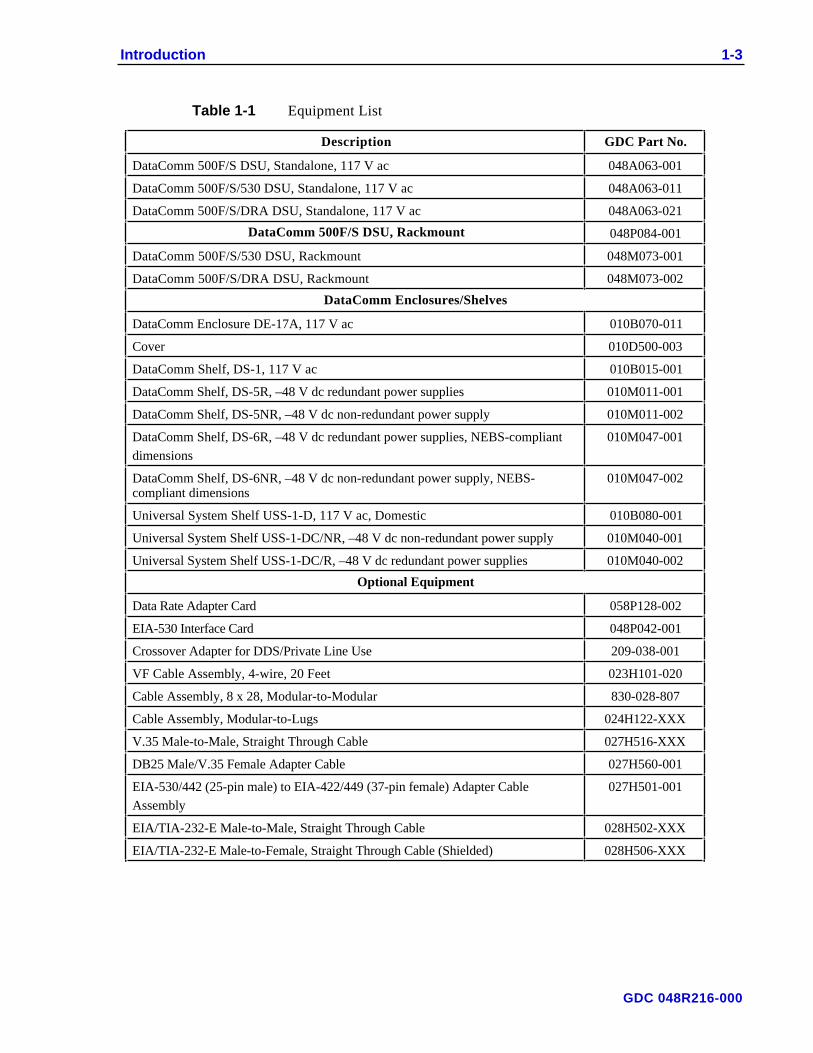
Table 1-1 lists the part numbers for the DataComm 500F/S’s standard and optionalequipment. Appendix A describes the units technical characteristics.
GDC 048R216-000
Introduction 1-3
Table 1-1 Equipment List
Description GDC Part No.
DataComm 500F/S DSU, Standalone, 117 V ac 048A063-001
DataComm 500F/S/530 DSU, Standalone, 117 V ac 048A063-011
DataComm 500F/S/DRA DSU, Standalone, 117 V ac 048A063-021
DataComm 500F/S DSU, Rackmount 048P084-001
DataComm 500F/S/530 DSU, Rackmount 048M073-001
DataComm 500F/S/DRA DSU, Rackmount 048M073-002
DataComm Enclosures/Shelves
DataComm Enclosure DE-17A, 117 V ac 010B070-011
Cover 010D500-003
DataComm Shelf, DS-1, 117 V ac 010B015-001
DataComm Shelf, DS-5R, –48 V dc redundant power supplies 010M011-001
DataComm Shelf, DS-5NR, –48 V dc non-redundant power supply 010M011-002
DataComm Shelf, DS-6R, –48 V dc redundant power supplies, NEBS-compliant
dimensions
010M047-001
DataComm Shelf, DS-6NR, –48 V dc non-redundant power supply, NEBS-compliant dimensions
010M047-002
Universal System Shelf USS-1-D, 117 V ac, Domestic 010B080-001
Universal System Shelf USS-1-DC/NR, –48 V dc non-redundant power supply 010M040-001
Universal System Shelf USS-1-DC/R, –48 V dc redundant power supplies 010M040-002
Optional Equipment
Data Rate Adapter Card 058P128-002
EIA-530 Interface Card 048P042-001
Crossover Adapter for DDS/Private Line Use 209-038-001
VF Cable Assembly, 4-wire, 20 Feet 023H101-020
Cable Assembly, 8 x 28, Modular-to-Modular 830-028-807
Cable Assembly, Modular-to-Lugs 024H122-XXX
V.35 Male-to-Male, Straight Through Cable 027H516-XXX
DB25 Male/V.35 Female Adapter Cable 027H560-001
EIA-530/442 (25-pin male) to EIA-422/449 (37-pin female) Adapter Cable
Assembly
027H501-001
EIA/TIA-232-E Male-to-Male, Straight Through Cable 028H502-XXX
EIA/TIA-232-E Male-to-Female, Straight Through Cable (Shielded) 028H506-XXX
GDC 048R216-000

2 Installation
OverviewThis chapter takes you step-by-step through the process of installing the DataComm500F/S in your communications system. We will discuss option selection, and themechanical and electrical installation.
Unpacking and HandlingInspect the unit for damage; if any is observed, notify the shipper immediately. Save thebox and packing material: you can use it to reship the unit, if necessary.
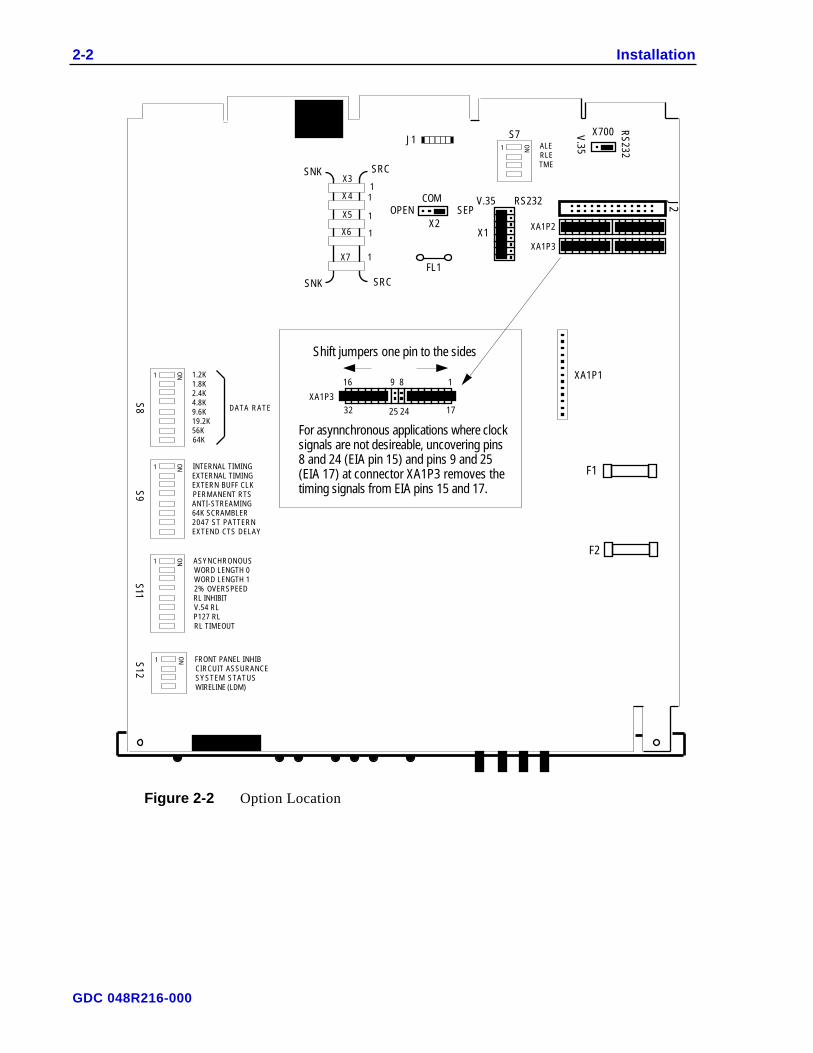
Option SelectionThe field-selectable options adapt the DataComm 500F/S to a variety of configurations.You select these options by positioning DIP switches on the DSU base card.
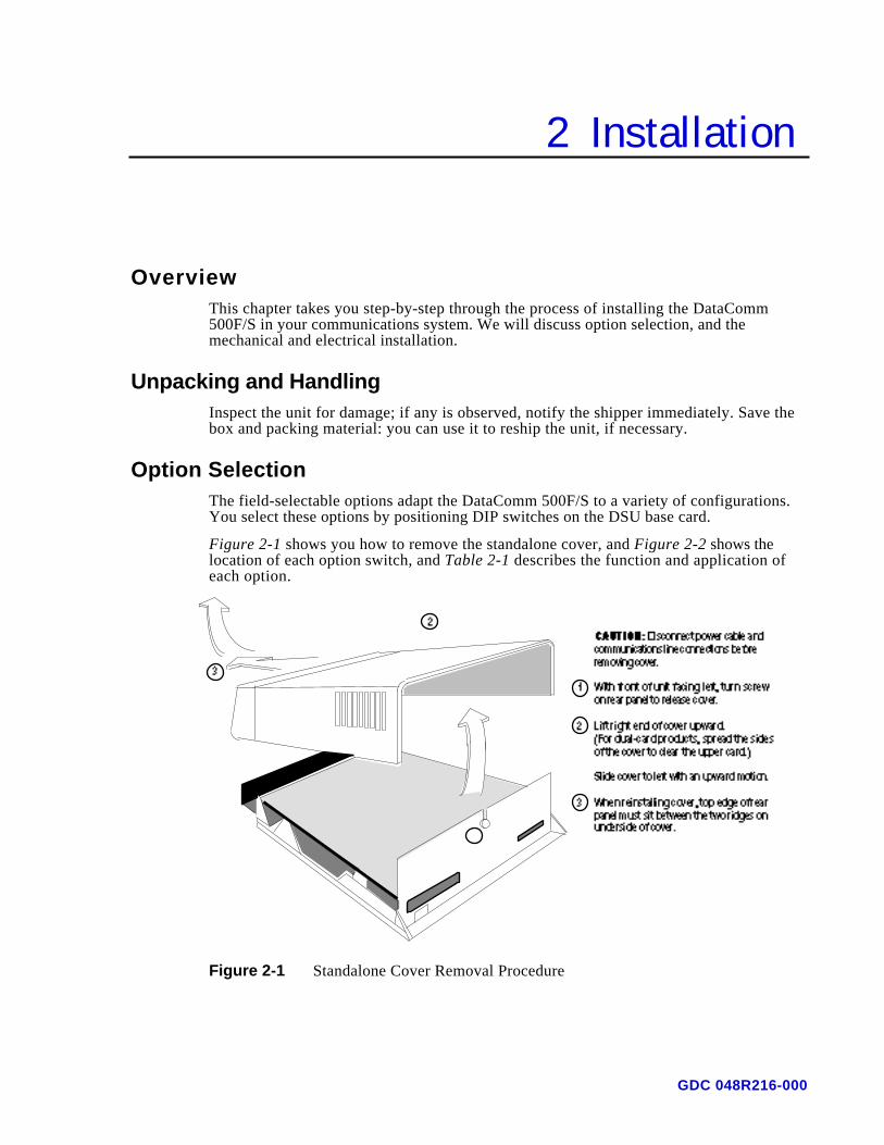
Figure 2-1 shows you how to remove the standalone cover, and Figure 2-2 shows thelocation of each option switch, and Table 2-1 describes the function and application ofeach option.
Figure 2-1 Standalone Cover Removal Procedure
GDC 048R216-000
2-2 Installation
FL1
F1
F2
S8
S12
S9
S11
V.35 RS232
X1XA1P3
XA1P2
J2
XA1P1
X2OPEN SEP
COM
J1 S7
RS
232
V.35
X700
SNK
SNK
SRC
SRC
X7
X6
X5
X4
X3
1
1
1
1
1
Shift jumpers one pin to the sides
For asynnchronous applications where clock signals are not desireable, uncovering pins 8 and 24 (EIA pin 15) and pins 9 and 25 (EIA 17) at connector XA1P3 removes the timing signals from EIA pins 15 and 17.
25 172432
916 8 1
XA1P3
1
ON
1
ON
1
ON
1
ON
1
ON
1.2K1.8K2.4K4.8K9.6K19.2K56K64K
DATA RATE
INTERNAL TIMINGEXTERNAL TIMINGEXTERN BUFF CLKPERMANENT RTSANTI-STREAMING64K SCRAMBLER2047 ST PATTERNEXTEND CTS DELAY
ASYNCHRONOUSWORD LENGTH 0WORD LENGTH 12% OVERSPEEDRL INHIBITV.54 RLP127 RLRL TIMEOUT
FRONT PANEL INHIBCIRCUIT ASSURANCESYSTEM STATUSWIRELINE (LDM)
ALERLETME
J 3
Figure 2-2 Option Location
GDC 048R216-000
Installation 2-3
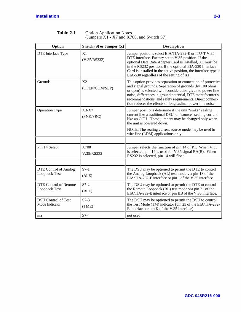
Table 2-1 Option Application Notes(Jumpers X1 - X7 and X700, and Switch S7)
Option Switch (S) or Jumper (X) Description
DTE Interface Type X1
(V.35/RS232)
Jumper positions select EIA/TIA-232-E or ITU-T V.35DTE interface. Factory set to V.35 position. If theoptional Data Rate Adapter Card is installed, X1 must bein the RS232 position. If the optional EIA-530 InterfaceCard is installed in the active position, the interface type isEIA-530 regardless of the setting of X1.
Grounds X2
(OPEN/COM/SEP)
This option provides separation or connection of protectiveand signal grounds. Separation of grounds (by 100 ohmsor open) is selected with consideration given to power linenoise, differences in ground potential, DTE manufacturer'srecommendations, and safety requirements. Direct connec-tion reduces the effects of longitudinal power line noise.
Operation Type X3-X7
(SNK/SRC)
Jumper positions determine if the unit “sinks” sealingcurrent like a traditional DSU, or “source” sealing currentlike an OCU. These jumpers may be changed only whenthe unit is powered down.
NOTE: The sealing current source mode may be used inwire line (LDM) applications only.
Pin 14 Select X700
V.35/RS232
Jumper selects the function of pin 14 of P1. When V.35is selected, pin 14 is used for V.35 signal BA(B). WhenRS232 is selected, pin 14 will float.
DTE Control of AnalogLoopback Test
S7-1
(ALE)
The DSU may be optioned to permit the DTE to controlthe Analog Loopback (AL) test mode via pin-18 of theEIA/TIA-232-E interface or pin J of the V.35 interface.
DTE Control of RemoteLoopback Test
S7-2
(RLE)
The DSU may be optioned to permit the DTE to controlthe Remote Loopback (RL) test mode via pin 21 of theEIA/TIA-232-E interface or pin BB of the V.35 interface.
DSU Control of TestMode Indicator
S7-3
(TME)
The DSU may be optioned to permit the DSU to controlthe Test Mode (TM) indicator (pin 25 of the EIA/TIA-232-E interface or pin K of the V.35 interface).
n/a S7-4 not used
GDC 048R216-000
2-4 Installation
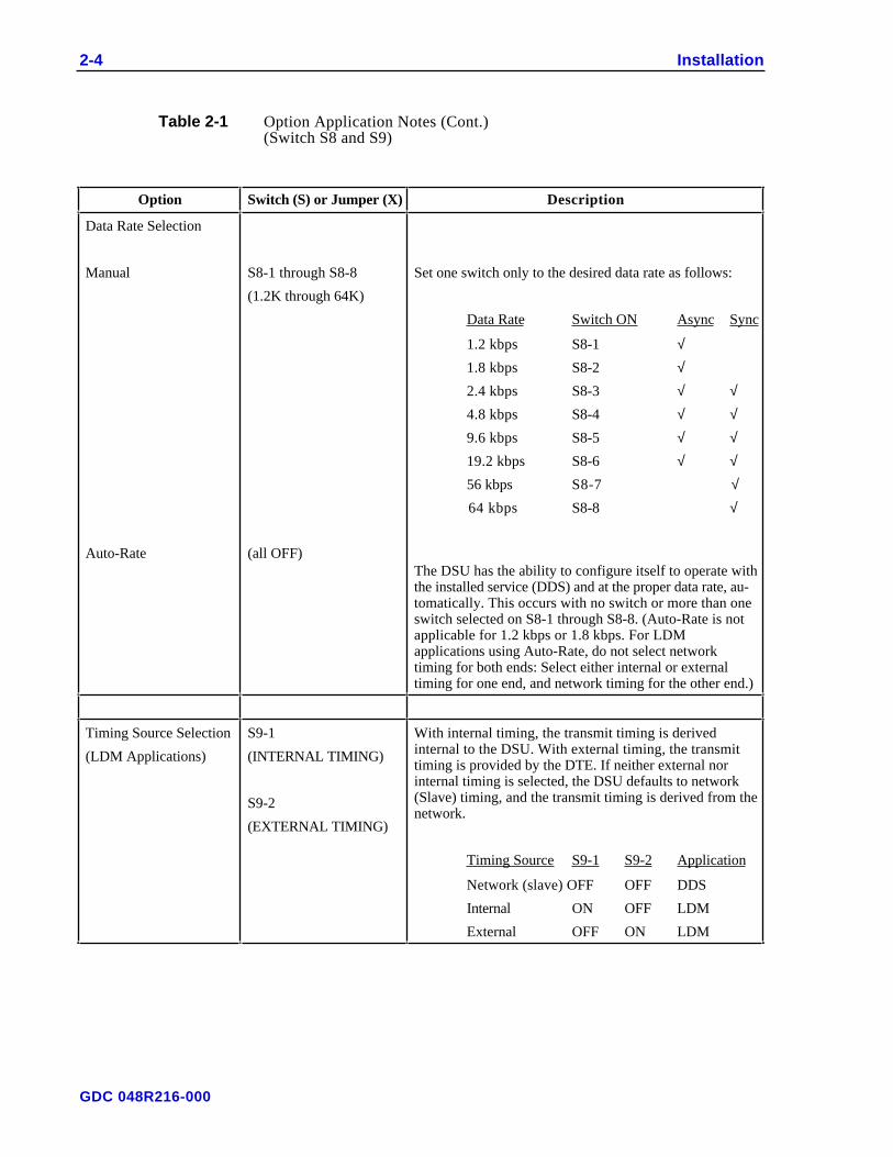
Table 2-1 Option Application Notes (Cont.)(Switch S8 and S9)
Option Switch (S) or Jumper (X) Description
Data Rate Selection
Manual
Auto-Rate
S8-1 through S8-8
(1.2K through 64K)
(all OFF)
Set one switch only to the desired data rate as follows:
Data Rate Switch ON Async Sync
1.2 kbps S8-1 √1.8 kbps S8-2 √2.4 kbps S8-3 √ √4.8 kbps S8-4 √ √9.6 kbps S8-5 √ √19.2 kbps S8-6 √ √56 kbps S8-7 √
64 kbps S8-8 √
The DSU has the ability to configure itself to operate withthe installed service (DDS) and at the proper data rate, au-tomatically. This occurs with no switch or more than oneswitch selected on S8-1 through S8-8. (Auto-Rate is notapplicable for 1.2 kbps or 1.8 kbps. For LDMapplications using Auto-Rate, do not select networktiming for both ends: Select either internal or externaltiming for one end, and network timing for the other end.)
Timing Source Selection
(LDM Applications)
S9-1
(INTERNAL TIMING)
S9-2
(EXTERNAL TIMING)
With internal timing, the transmit timing is derivedinternal to the DSU. With external timing, the transmittiming is provided by the DTE. If neither external norinternal timing is selected, the DSU defaults to network(Slave) timing, and the transmit timing is derived from thenetwork.
Timing Source S9-1 S9-2 Application
Network (slave) OFF OFF DDS
Internal ON OFF LDM
External OFF ON LDM
GDC 048R216-000

Installation 2-5
Table 2-1 Option Application Notes (Cont.)(Switch S9 and S11)
Option Switch (S) or Jumper (X) Description
External Transmit BufferClock
S9-3
(EXTERN BUFF CLK)
When ON, and when the timing source is Internal orSlave, the input clock to the buffer is the DTE clock(external). When OFF, the input clock to the buffer is theDSU transmit timing. When the timing source isExternal, the buffer clock is always the DTE clock.
Permanent RTS S9-4
(PERMANENT RTS)
When ON, both RTS and CTS remain ON regardless ofthe state of the attached DTE (the transmitter is ON regard-less of the status of the RTS interface lead) When OFF,the RTS-to-CTS delay is determined by S9-8.
Anti-Streaming S9-5
(ANTI-STREAMING)
When ON, the DSU transmitter is forced OFF (idle) if theDTE RTS lead remains ON for more than 20 seconds.Anti-Streaming releases when the RTS interface lead turnsOFF and remains OFF for 100 ms. When a streamingcondition is detected, the TM/ALM LED blinks, DTE pin25 (TM) toggles and “AS” is displayed. When OFF, Anti-Streaming is disabled.
64K Scrambler
(Available when oper-
ating at 64 kbps only)
S9-6
(64K SCRAMBLER)
When ON, a scrambler and descrambler are inserted intothe data path. When OFF, they are bypassed.
2047 Self-Test Pattern S9-7
(2047 ST PATTERN)
When ON, a 2047-bit test pattern is used during Self-Test.When OFF, a 511-bit test pattern is used.
Extended CTS Delay S9-8
(EXTEND CTS DELAY)
RTS-to-CTS delay. Normal (3-byte delay) is OFF;extended (45 ms delay) is ON. Use extended delay in anapplication such as an analog modem tail circuit on the farend where data may be lost if CTS is asserted too soon.(This option is ignored when S9-4 is OFF.)
Asynchronous S11-1
(ASYNCHRONOUS)
When ON, forces the DSU to perform an asynchronous tosynchronous conversion, allowing customer equipment toasynchronously transmit on the data path. When OFF,synchronous mode is selected.
Word Size Selection S11-2
(WORD LENGTH 0)
S11-3
(WORD LENGTH 1)
These two switches select the asynchronous word size(number of bits per character). The option is ignored insynchronous mode or 56 and 64 kbps operation.
Word Size S11-2 S11-3
11 ON ON
10 OFF OFF
09 OFF ON
08 ON OFF
Extended Overspeed S11-4
(2% OVERSPEED)
When ON and in asynchronous operation, up to 2.3% datarate overspeed can be accommodated. When OFF, a defaultof 1% overspeed is selected.
GDC 048R216-000
2-6 Installation
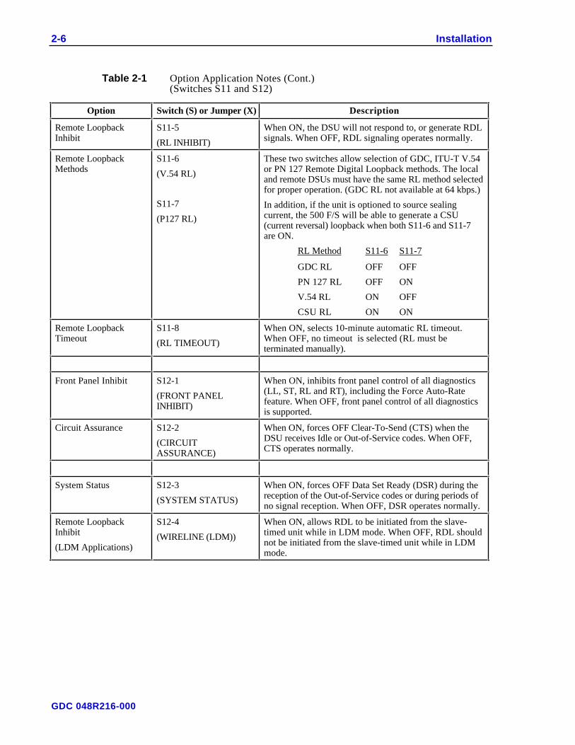
Table 2-1 Option Application Notes (Cont.)(Switches S11 and S12)
Option Switch (S) or Jumper (X) Description
Remote LoopbackInhibit
S11-5
(RL INHIBIT)
When ON, the DSU will not respond to, or generate RDLsignals. When OFF, RDL signaling operates normally.
Remote LoopbackMethods
S11-6
(V.54 RL)
S11-7
(P127 RL)
These two switches allow selection of GDC, ITU-T V.54or PN 127 Remote Digital Loopback methods. The localand remote DSUs must have the same RL method selectedfor proper operation. (GDC RL not available at 64 kbps.)
In addition, if the unit is optioned to source sealingcurrent, the 500 F/S will be able to generate a CSU(current reversal) loopback when both S11-6 and S11-7are ON.
RL Method S11-6 S11-7
GDC RL OFF OFF
PN 127 RL OFF ON
V.54 RL ON OFF
CSU RL ON ON
Remote LoopbackTimeout
S11-8
(RL TIMEOUT)
When ON, selects 10-minute automatic RL timeout.When OFF, no timeout is selected (RL must beterminated manually).
Front Panel Inhibit S12-1
(FRONT PANELINHIBIT)
When ON, inhibits front panel control of all diagnostics(LL, ST, RL and RT), including the Force Auto-Ratefeature. When OFF, front panel control of all diagnosticsis supported.
Circuit Assurance S12-2
(CIRCUITASSURANCE)
When ON, forces OFF Clear-To-Send (CTS) when theDSU receives Idle or Out-of-Service codes. When OFF,CTS operates normally.
System Status S12-3
(SYSTEM STATUS)
When ON, forces OFF Data Set Ready (DSR) during thereception of the Out-of-Service codes or during periods ofno signal reception. When OFF, DSR operates normally.
Remote LoopbackInhibit
(LDM Applications)
S12-4
(WIRELINE (LDM))
When ON, allows RDL to be initiated from the slave-timed unit while in LDM mode. When OFF, RDL shouldnot be initiated from the slave-timed unit while in LDMmode.
GDC 048R216-000
Installation 2-7
Installation ProceduresYou may install the unit in a standalone DataComm Enclosure or rackmount in aDataComm or Universal System Shelf (USS). Either installation should be located in aventilated area where the ambient temperature does not exceed 122°F (50°C). Do notinstall the unit directly above equipment that generates a large amount of heat (such aspower supplies).
Standalone InstallationIf it is necessary to remove the component cards from the standalone base, disconnect thepower supply connector from J1, which is mounted at the rear center of the base card.When reinstalling the component cards to the base, reinstall the connector at J1. SeeFigure 2-1.
Rackmount InstallationYou may also mount the DataComm 500F/S in a DataComm Shelf (DS-1, DS-5 or DS-6)which supports as many as 16 DSUs. The DSU may be installed in any unused slot in theshelf. To install the unit in the shelf, proceed as follows:
1. Position the plug-in module in the top and bottom slot guides with the GDC logoon top, and carefully slide the assembly into the slot until it stops at the rearconnectors.
2. Push the front panel with both hands until the assembly seats in the rear connectors.
The Universal System Shelf (USS) may also be used and accommodates 16 DSUs. TheUSS uses harness cards and backplanes configured to occupy one slot in the shelf foreach DSU.
Each backplane assembly is keyed by a tab located at the bottom of the harness card.This tab fits into a slot that is part of the shelf and prevents the backplanes from beinginserted incorrectly in the shelf.
To install the DSU into the USS shelf, proceed as follows:
1. Loosen the backplane screws and install the plug-in module from the front of theshelf by sliding it into the card guides. Seat firmly into the mating connectors onthe backplane using both hands.
2. Tighten the backplane screws. This assures perfect alignment of the plug-inmodules in the card guides and the mating connectors on the backplane and allowsfor easy removal of the plug-in modules. Plug in the four-pin cable harness on thebackplane adapter to the shelf power connector located directly above thebackplane adapter.
GDC 048R216-000
2-8 Installation
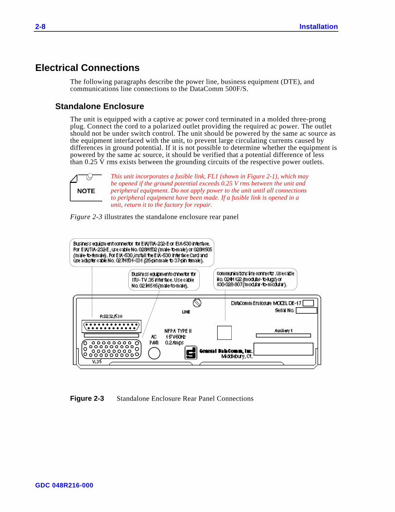
Electrical ConnectionsThe following paragraphs describe the power line, business equipment (DTE), andcommunications line connections to the DataComm 500F/S.
Standalone EnclosureThe unit is equipped with a captive ac power cord terminated in a molded three-prongplug. Connect the cord to a polarized outlet providing the required ac power. The outletshould not be under switch control. The unit should be powered by the same ac source asthe equipment interfaced with the unit, to prevent large circulating currents caused bydifferences in ground potential. If it is not possible to determine whether the equipment ispowered by the same ac source, it should be verified that a potential difference of lessthan 0.25 V rms exists between the grounding circuits of the respective power outlets.
NOTE
This unit incorporates a fusible link, FL1 (shown in Figure 2-1), which maybe opened if the ground potential exceeds 0.25 V rms between the unit andperipheral equipment. Do not apply power to the unit until all connectionsto peripheral equipment have been made. If a fusible link is opened in aunit, return it to the factory for repair.
Figure 2-3 illustrates the standalone enclosure rear panel
Figure 2-3 Standalone Enclosure Rear Panel Connections
GDC 048R216-000
Installation 2-9
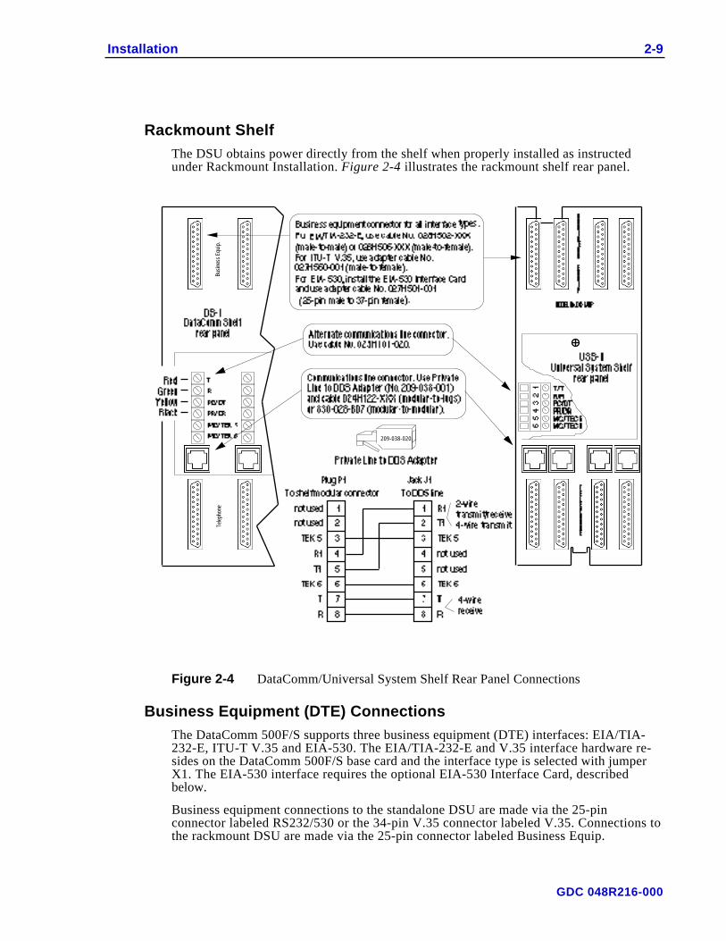
Rackmount ShelfThe DSU obtains power directly from the shelf when properly installed as instructedunder Rackmount Installation. Figure 2-4 illustrates the rackmount shelf rear panel.
209-038-020
Busi
ness
Equ
ip.
Tele
phon
e
Figure 2-4 DataComm/Universal System Shelf Rear Panel Connections
Business Equipment (DTE) ConnectionsThe DataComm 500F/S supports three business equipment (DTE) interfaces: EIA/TIA-232-E, ITU-T V.35 and EIA-530. The EIA/TIA-232-E and V.35 interface hardware re-sides on the DataComm 500F/S base card and the interface type is selected with jumperX1. The EIA-530 interface requires the optional EIA-530 Interface Card, describedbelow.
Business equipment connections to the standalone DSU are made via the 25-pinconnector labeled RS232/530 or the 34-pin V.35 connector labeled V.35. Connections tothe rackmount DSU are made via the 25-pin connector labeled Business Equip.
GDC 048R216-000
2-10 Installation
Appendix A describes the signals exchanged through each of the business equipmentinterfaces.
Communications Line ConnectionsWhen the DSU is installed in the standalone enclosure, the DSU is connected to thecommunications line using the modular jack at the rear panel.
The modular jacks transmit pair is on pins 1 and 2, and the receive pair is on pins 7 and8. Pin 1 is on the left and pin 8 is on the right, when the jack is viewed from the rear.
If the DSU is rackmounted in the DataComm Shelf DS-l, the four wire communicationsline is connected to the top four screws of the terminal block mounted on the shelf's rearpanel. If the unit is mounted in the Universal System Shelf, the plastic cover attached atthe rear of the backplane must first be removed to expose the VF terminal blocks. Theseblocks accommodate wires that do not have terminal lugs. Remove the lugs and a portionof the insulation on the existing cable and insert the wires into the block by first `
In either case, before making the connection, verify that the terminal block correspondsto the shelf receptacle in which the DSU plug-in module is installed.
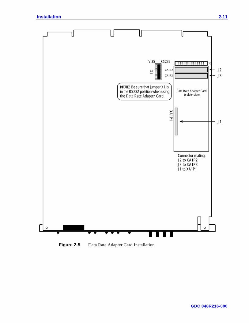
Data Rate Adapter CardAn optional Data Rate Adapter Card is available as a factory installed option, or as a fieldupgrade kit. The Data Rate Adapter Card (GDC Part No. 058P128-002) plugs into theDataComm 500F/S base card, as illustrated in Figure 2-5. You cannot install the Data RateAdapter Card and the EIA-530 Interface Card at the same time.
The Data Rate Adapter Card adapts synchronous and asynchronous DTE datatransmission speeds of 19.2 kbps and slower to an aggregate line speed of 56 or 64 kbps.Rate adaptation is provided for point-to-point and multipoint applications.
For complete operating and installation instructions applicable to the Data Rate AdapterCard, refer to Publication No. 048R162-A1.
GDC 048R216-000
Installation 2-11
V.35 RS232
X1
NOTE: Be sure that jumper X1 is in the RS232 position when using the Data Rate Adapter Card.
J2
XA
1P1
XA1P2
XA1P3
J2
J3
Data Rate Adapter Card(solder side)
J1
Connector mating:J2 to XA1P2J3 to XA1P3J1 to XA1P1
Figure 2-5 Data Rate Adapter Card Installation
GDC 048R216-000
2-12 Installation
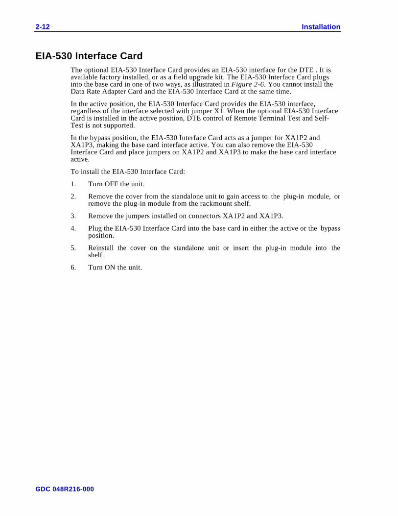
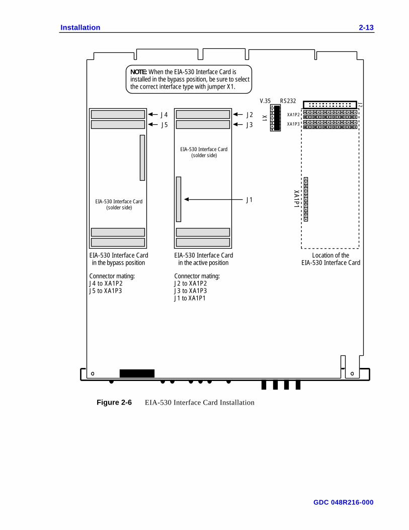
EIA-530 Interface CardThe optional EIA-530 Interface Card provides an EIA-530 interface for the DTE . It isavailable factory installed, or as a field upgrade kit. The EIA-530 Interface Card plugsinto the base card in one of two ways, as illustrated in Figure 2-6. You cannot install theData Rate Adapter Card and the EIA-530 Interface Card at the same time.
In the active position, the EIA-530 Interface Card provides the EIA-530 interface,regardless of the interface selected with jumper X1. When the optional EIA-530 InterfaceCard is installed in the active position, DTE control of Remote Terminal Test and Self-Test is not supported.
In the bypass position, the EIA-530 Interface Card acts as a jumper for XA1P2 andXA1P3, making the base card interface active. You can also remove the EIA-530Interface Card and place jumpers on XA1P2 and XA1P3 to make the base card interfaceactive.
To install the EIA-530 Interface Card:
1. Turn OFF the unit.
2. Remove the cover from the standalone unit to gain access to the plug-in module, orremove the plug-in module from the rackmount shelf.
3. Remove the jumpers installed on connectors XA1P2 and XA1P3.
4. Plug the EIA-530 Interface Card into the base card in either the active or the bypassposition.
5. Reinstall the cover on the standalone unit or insert the plug-in module into theshelf.
6. Turn ON the unit.
GDC 048R216-000
Installation 2-13
V.35 RS232
X1
NOTE: When the EIA-530 Interface Card is installed in the bypass position, be sure to select the correct interface type with jumper X1.
J2
J3
EIA-530 Interface Card(solder side)
EIA-530 Interface Cardin the active position
J1
Connector mating:J2 to XA1P2J3 to XA1P3J1 to XA1P1
J4
J5
EIA-530 Interface Cardin the bypass position
Connector mating:J4 to XA1P2J5 to XA1P3
EIA-530 Interface Card(solder side)
J2
XA
1P1
XA1P2
XA1P3
Location of theEIA-530 Interface Card
Figure 2-6 EIA-530 Interface Card Installation
GDC 048R216-000
2-14 Installation
Preoperational CheckVerify that option selection is the same as illustrated in Figure 2-2. All option switchesand jumpers (except X2) are in the left (OFF) position.
When you turn power on, the DSU lights all of its LEDs, displays its firmware checksumfor five seconds, and then performs an Analog Loopback Self-Test. It displays the resultof this test as either “PASS” or “FAIL.” If the DSU fails the power-up self-test, Recheckthe cable and line connections, and verify that the remote DSU is a compatible type (e.g.,a DSU operating at the same data rate). Also verify that the DDS network is operating atthe correct rate.
If the telco has changed the rate, either force the DSU to Auto-Rate by engaging frontpanel push buttons LL and RL simultaneously for at least five seconds or select the newrate with option switch S8.
With Auto-Rate enabled, the DSU continually attempts to determine the line type and rateon power-up or when the line signal was absent for longer than 10 seconds and recov-ered. The DSU requires a full Auto-Rate cycle to accurately determine the line type andrate.
Before you connect the DSU to the communications line or DTE, you can give it afurther preoperational check by performing a Line Loopback Self-Test (refer to Chapter4) to verify operation.
If the transmit and receive lines are transposed (crossed), the TM/ALM LED flashes andthe message “LinE” appears. Use of the wrong cable or mis-wiring of the telephonecompany-provided network interface may cause this problem and must be corrected.
When the unit is optioned to generate sealing current and after the DataComm 500 F/Scompletes its startup, observe the front panel TM/ALM LED. A flashing TM/ALM LEDand no alarm messages on the display window indicate a lack of continuity in the localloop. If the ALM/TM LED is off, sealing current continuity is complete.
If the DSU passes the test, but subsequently fails to perform data communications, it isprobably not at fault. There is either an error in option selection or installation, or a faultycommunications line or remote installation. Do not attempt to repair the unit, refer toDataComm Services listed in the Preface of this manual.
GDC 048R216-000
3 Operation
OverviewThis chapter describes the operations of the DataComm 500F/S which are controlledautomatically after it is properly installed. It has no operating instructions (except for testprocedures given in Chapter 4, Tests). This chapter also describes the front panel controlsand indicators of the unit that you may use to check the operation.
Controls And IndicatorsFigures 3-1 and 3-2 illustrate the DSUs front panel and explain the function of eachcontrol and indicator.
ON500F/S TM / ALMCORS CSRDSDLL ST RL RT
Engaging this push button causes the local DSU's test pattern generator to generate and check a selectable test pattern. If the DSU detects errors, it displays the percentage of error-free-seconds ("nn.nE"). When the DSU is in a self-test mode, and you disengage then engage this push button (within approximately 2 seconds), the percentage of error-free seconds counter is cleared (the test pattern generator is not affected).
Engaging this push button initiates Remote Digital Loopback (i.e., places the remote DSU in Remote Terminal Loopback).
Engaging this push button places the local DSU in Line Loopback.
With Auto-Rate enabled, engaging LL and RL simultaneously for at least 5 seconds forces the DSU to Auto-Rate. Before performing Auto-Rate, the DSU alternately displays "Auto" and the current rate, and you can cancel Auto-Rate by disengaging the push buttons.
Engaging this push button places the local DSU in Remote Terminal Loopback.
Figure 3-1 Front Panel Push Buttons
GDC 048R216-000
3-2 Operation
ON500F/S TM / ALMCORS CSRDSD
LL ST RL RT
ON when DSU has ac voltage and DSU power supply is 5 V dc.
ON when DTE is ready to send data. Also ON during self-test modes or when Permanent RTS option is enabled.
ON when DSU is ready to send data. OFF during self-test modes.
ON when DSU is receiving data. OFF during self-test modes.
ON when a space bit is present in send data.
ON when received data is a space.
ON when DSU is in test mode or flashes for an alarm state.
See Sheet 2 for a description of the display.
Figure 3-2 Front Panel Indicators And Display (Sheet 1 Of 2)
GDC 048R216-000

Operation 3-3
Data rate is 1.2 kbps
Data rate is 1.8 kbps
Data rate is 2.4 kbps
Data rate is 4.8 kbps
Data rate is 9.6 kbps
Data rate is 19.2 kbps
Data rate is 56 kbps
Data rate is 64 kbps
Out of Service alarm (TM/ALM LED flashes)
Unit passed Power-up Self-Test
Unit failed Power-up Self-Test, Line Loopback with Self-Test, V.54 RL or GDC RL
Auto-Rate in progress; "Auto" and current rate alternate for 5 seconds preceding a forced Auto-Rate
DDS communication line crossed alarm (TM/ALM LED flashes)
Streaming DTE alarm (TM/ALM LED flashes)
DTE-initiated Analog Loopback
Line Loopback from front panel push button
Line Loopback from telco Serving Test Center (STC) current reversal
Remote Terminal test from STC codes
Remote Loopback from front panel push button
Remote Loop condition (initiated from other end)
Power-up Self-Test
Line Loopback with Self-Test from front panel push button
Remote Loopback with Self-Test from front panel push button
Percentage of error-free seconds during Self-Test mode (00.0E to 99.9E)
DTE-initiated Remote Loopback
No Signal alarm (TM/ALM LED flashes)
511 Self-Test pattern selected
2047 Self-Test pattern selected
PN 127 RL test selected
V.54 RL test selected
GDC RL test selected
Reset percentage of error-free seconds counter during Self-Test
When alternating with nn.nE, error-free seconds is being computed.When on steady, test is 100% error free.
18.2 hour test is finished
18.2 hour test is finished
18.2 hour test is finished
Alphanumeric characters 0 to 9, A to F, during Power-up Self-Test displays firmware checksum for 5 seconds
Remote Terminal Loopback from front panel push button
Current Reversal RL test selected.Current Reversal with self-test from front panel push button.
Figure 3-2 Panel Indicators And Display (Sheet 2 Of 2)
GDC 048R216-000

4 Tests
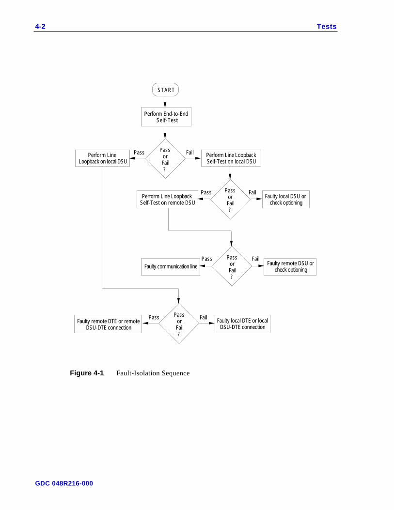
OverviewThis chapter describes the tests that you can perform after installing the DataComm500F/S or whenever you must check its operation. You can also use these tests to isolateproblems in the data communications system (see Table 4-1, and Figure 4-1).
The SD and RD LEDs may appear to be ON or to flicker, depending on the data rate atwhich you are testing the unit. When the DSU is operating at the higher rates (above 9600bps), the indicators may appear to be solidly ON; below that they may appear to flicker.The test descriptions and front panel indicators shown in the illustrations assume that theunit has established its test and is operating at 9600 bps or below.
1. Diagnostics may be controlled from the front panel push buttons, the DTEinterfaces or from the telco Serving Test Center (STC), depending on the specifictest.
2. You can option the DSU to permit the DTE to control Analog Loopback Test andRemote Loopback (refer to Table 2-1).
3. To force the DSU to Auto-Rate and determine the line type and rate, engage frontpanel push buttons LL and RL simultaneously for at least five seconds. (Before per-forming Auto-Rate, the DSU displays “Auto” and you can cancel Auto-Rate byreleasing the push buttons.) When Auto-Rate is complete, the DSU displays the linerate. If it is not the expected rate, contact the telco.
Table 4-1 Diagnostic Test Priorities
Priority Test Means of Activation Display
1 CSU Loopback STC (current reversal) CSU
2 LL/LL-ST Front Panel LL/LL-S
3 DSU Loopback STC (Codes) (if activated first, has priority over LL/LL-ST) dSU
4 RT (Local) Front Panel rtLb
5a RL/RL-ST Front Panel when optioned to sink sealing current rL/rL-S
5b CURR/CR-ST Front Panel when optioned to source sealing current CUrr/Cr-ST
6 AL DTE (if activated first, has priority over DSU Loopback) d-AL
7 RL DTE d-rL
8 ST Front Panel EFS
9 RT (Remote) (from remote RL) LOOP
GDC 048R216-000
4-2 Tests
START
Perform Line Loopback on local DSU
Perform Line Loopback Self-Test on local DSU
Perform Line Loopback Self-Test on remote DSU
Perform End-to-End Self-Test
Faulty local DSU or check optioning
Faulty communication line
Faulty remote DTE or remote DSU-DTE connection
Faulty local DTE or local DSU-DTE connection
PassorFail?
Pass Fail
PassorFail?
Pass Fail
PassorFail?
Pass FailFaulty remote DSU or
check optioning
PassorFail?
Pass Fail
Figure 4-1 Fault-Isolation Sequence
GDC 048R216-000
Tests 4-3
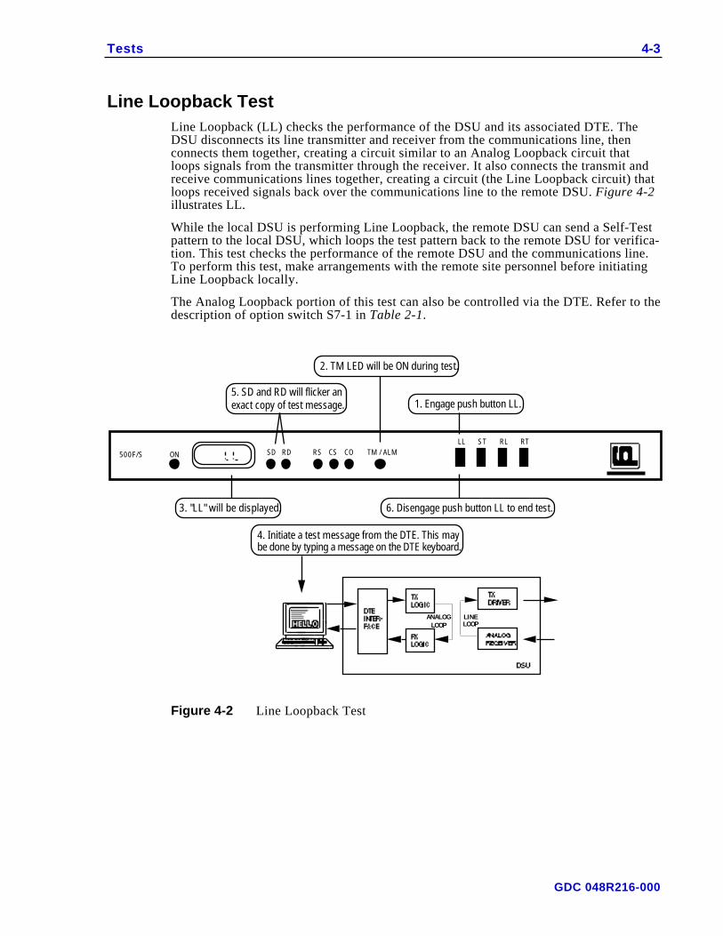
Line Loopback TestLine Loopback (LL) checks the performance of the DSU and its associated DTE. TheDSU disconnects its line transmitter and receiver from the communications line, thenconnects them together, creating a circuit similar to an Analog Loopback circuit thatloops signals from the transmitter through the receiver. It also connects the transmit andreceive communications lines together, creating a circuit (the Line Loopback circuit) thatloops received signals back over the communications line to the remote DSU. Figure 4-2illustrates LL.
While the local DSU is performing Line Loopback, the remote DSU can send a Self-Testpattern to the local DSU, which loops the test pattern back to the remote DSU for verifica-tion. This test checks the performance of the remote DSU and the communications line.To perform this test, make arrangements with the remote site personnel before initiatingLine Loopback locally.
The Analog Loopback portion of this test can also be controlled via the DTE. Refer to thedescription of option switch S7-1 in Table 2-1.
ON500F/S TM / ALMCORS CSRDSD
LL ST RL RT
ANALOGLOOP
LINELOOP
1. Engage push button LL.
2. TM LED will be ON during test.
5. SD and RD will flicker an exact copy of test message.
3. "LL" will be displayed. 6. Disengage push button LL to end test.
4. Initiate a test message from the DTE. This may be done by typing a message on the DTE keyboard.
Figure 4-2 Line Loopback Test
GDC 048R216-000
4-4 Tests
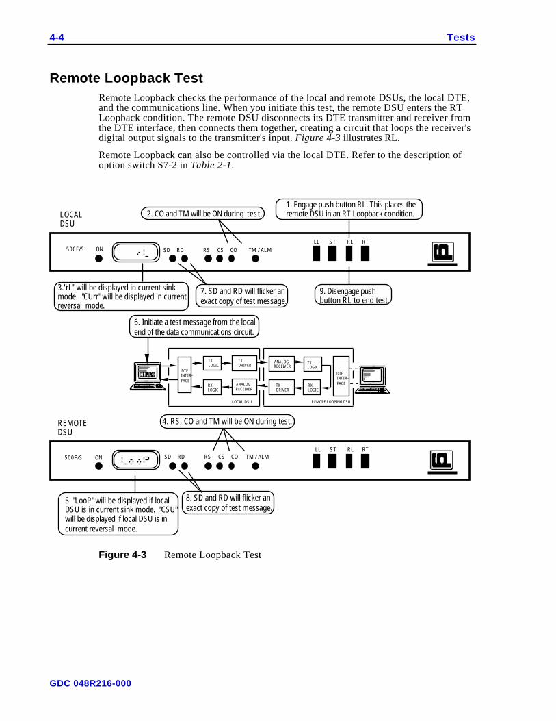
Remote Loopback TestRemote Loopback checks the performance of the local and remote DSUs, the local DTE,and the communications line. When you initiate this test, the remote DSU enters the RTLoopback condition. The remote DSU disconnects its DTE transmitter and receiver fromthe DTE interface, then connects them together, creating a circuit that loops the receiver'sdigital output signals to the transmitter's input. Figure 4-3 illustrates RL.
Remote Loopback can also be controlled via the local DTE. Refer to the description ofoption switch S7-2 in Table 2-1.
TM / ALMCORS CSRDSD
LL ST RL RT
LL ST RLTM / ALMCORS CSRDSD
RT
ON
LOCALDSU
REMOTEDSU
1. Engage push button RL. This places the remote DSU in an RT Loopback condition.2. CO and TM will be ON during test.
3."rL" will be displayed in current sink mode. "CUrr" will be displayed in current reversal mode..
7. SD and RD will flicker an exact copy of test message.
9. Disengage push button RL to end test.
6. Initiate a test message from the local end of the data communications circuit.
4. RS, CO and TM will be ON during test.
5. "LooP" will be displayed if local DSU is in current sink mode. "CSU" will be displayed if local DSU is in current reversal mode.
8. SD and RD will flicker an exact copy of test message.
DTEINTER-FACE
TXLOGIC
RXLOGIC
TXDRIVER
ANALOGRECEIVER
ANALOGRECEIVER
TXDRIVER
TXLOGIC
RXLOGIC
DTEINTER-FACE
REMOTE LOOPING DSULOCAL DSU
500F/S ON
500F/S
Figure 4-3 Remote Loopback Test
GDC 048R216-000

Tests 4-5
Remote Terminal TestRemote Terminal (RT) test checks the performance of the local and remote DSUs, theremote DTE, and the communications line. When you initiate this test, the local loopingDSU disconnects its DTE transmitter and receiver from the DTE interface, then connectsthem together, creating a circuit that loops the receiver's digital output signals to the trans-mitter's input. Figure 4-4 illustrates RT.
1. Engage push button RT at the looping (local) DSU.
3."rtLb" will be displayed. 5. SD and RD will flicker at the remote DSU.
7. Disengage push button RT at the local DSU to end test.
4. Initiate a test message at the remote DSU.
2. RS and TM will light at the local DSU.
6. An exact copy of the test message should be received at the remote DSU.
ON500F/S
LL ST RL
TM / ALMCORS CSRDSD
RT
Figure 4-4 Remote Terminal Test
GDC 048R216-000

4-6 Tests
Self-TestsThe Self-Test function causes the DSU to generate a test pattern and monitor the receivedsignal for errors in the received test pattern. Option switch S9-7 selects either a 511- or2047-bit test pattern for the pattern generator and error detector. Figures 4-5 through 4-7illustrate Self-Test. If the DSU detects any errors, the front panel displays the percentageof error-free seconds. You can use Self-Test in place of DTE-generated test messages forthe Line Loopback and Remote Loopback tests.
Self-Test computes the percentage of error-free seconds for up to 18.2 hours. At the endof this time, the DSU freezes the percentage of error-free seconds display, although theSelf-Test generator and checker continue to function. The maximum Self-Test timereached is indicated by lighting all of the decimal points.
During Self-Test, if you disengage the Self-Test push button and then engage it withintwo seconds, the DSU resets the percentage of error-free seconds counter.
ON500F/S TM / ALMCORS CSRDSD
LL ST RL RT
LOCALDSU
1. Engage push button LL.
2. Engage push button ST.3. RS, CO and TM will be ON during test.
4 "LL-S" will be displayed if no errors are detected. *
5. SD and RD will flicker. 6. Disengage push buttons ST and LL to end test.
If an error is detected, the "FAIL" message will be displayed, the test will be terminated, and the DSU will resume its previous mode."LL-S" will be displayed as "L.L.-.S." when the maximum Self-Test time has been reached.
LINELOOP
DSU
PATTERNGENERATOR
TXLOGIC
ERRORDETECTOR
RXLOGIC
ANALOGLOOP SELF-TEST
*
Figure 4-5 Line Loopback Self-Test
GDC 048R216-000
Tests 4-7
LOCALDSU
1. Engage push button RL. This places the remote DSU in an RT Loopback condition.
2. After "rL" appears on display, engage push button ST.
3. RS, CO and TM will be ON during test.
ON COLL ST RL
RS CSRDSDRT
4. "rL-S" will be displayed in current sink mode, Cr-S will be displayed in current reversal mode, if no errors are detected *.
5. SD and RD will flicker. 9. Disengage push buttons ST and RL to end test.
6. RS, CO and TM will be ON during test.
7. "LooP" will be displayed if local
DSU is in current sink mode. "CSU" will be displayed if the local DSU is in current reversal mode.
"nn.nE" will be alternately displayed with "rL-S" if errors are detected."nn.n" denotes percentage of error-free seconds."rL-S" will be displayed as "r.L.-.S." when the maximum Self-Test time has been reached. Cr-S is displayed as "C.r. -.S." when the maximum self-test time has been reached.
*
REMOTEDSU
ON COLL ST RL
RS CSRDSDRT
8. SD and RD will flicker.
DSU
PATTERNGENERATOR
TXLOGIC
ERRORDETECTOR
RXLOGIC
DTEINTER-FACE
DTEINTER-FACE
TXDRIVER
TXDRIVER
ANALOGRECEIVER
ANALOGRECEIVER
TXLOGIC
RXLOGIC
REMOTE LOOPING DSU
500F/S
500F/S
Figure 4-6 Remote Loopback Self-Test
GDC 048R216-000

4-8 Tests
End-To-End Self-TestIn addition to using the Self-Test function in conjunction with other test features, you canSelf-Test independently. In End-to-End Self-Test, the local and remote DSUs exchangeSelf-Test patterns to check the performance of the communications line and the local andremote DSUs (not including the DSUs' DTE interfaces). Option switch S9-7 selects eithera 511- or 2047-bit test pattern for the pattern generator and error detector. Figure 4-7illustrates End-to-End Self-Test.
ON CS
LOCAL AND REMOTEDSUs
1. Engage push button ST on local DSU. Direct attendant to engage push button ST on remote DSU.
2. SD and RD will flicker.
3. "EFS" will be displayed if no errors are detected.
4. Disengage push button ST to end test.
5. When push button ST is disengaged then engaged again (within about 2 seconds), the percentage of error-free seconds counter is cleared (the test pattern generator is not affected).
RS, CO and TM will be ON during test.
are detected" nn.n" denotes "nn.nE" will be alternately displayed with "EFS" if errors
percentage of error-free seconds."EFS" will be displayed as "E.S.F." when the maximum Self-Test time has been reached.
*
500F/S COLL ST RL
RSRDSDRT
TM/ALM
PATTERNGENERATOR
DTEINTER-FACE
LOCAL DSU
TXLOGIC
RXLOGIC
ERRORDETECTOR
TXDRIVER
ANALOGRECEIVER
DTEINTER-FACE
ERRORDETECTOR
TXDRIVER
ANALOGRECEIVER
TXLOGIC
RXLOGIC
REMOTE DSU
PATTERNGENERATOR
Figure 4-7 End-To-End Self-Test
GDC 048R216-000
Tests 4-9
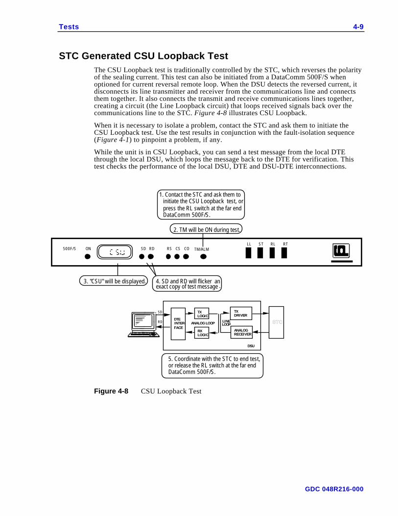
STC Generated CSU Loopback TestThe CSU Loopback test is traditionally controlled by the STC, which reverses the polarityof the sealing current. This test can also be initiated from a DataComm 500F/S whenoptioned for current reversal remote loop. When the DSU detects the reversed current, itdisconnects its line transmitter and receiver from the communications line and connectsthem together. It also connects the transmit and receive communications lines together,creating a circuit (the Line Loopback circuit) that loops received signals back over thecommunications line to the STC. Figure 4-8 illustrates CSU Loopback.
When it is necessary to isolate a problem, contact the STC and ask them to initiate theCSU Loopback test. Use the test results in conjunction with the fault-isolation sequence(Figure 4-1) to pinpoint a problem, if any.
While the unit is in CSU Loopback, you can send a test message from the local DTEthrough the local DSU, which loops the message back to the DTE for verification. Thistest checks the performance of the local DSU, DTE and DSU-DTE interconnections.
ON COLL ST RL
RS CSRDSDRT
ANALOG LOOP LINELOOP
SD
RD
2. TM will be ON during test.
3. "CSU" will be displayed. 4. SD and RD will flicker an exact copy of test message .
1. Contact the STC and ask them to initiate the CSU Loopback test, or press the RL switch at the far end DataComm 500F/S.
5. Coordinate with the STC to end test, or release the RL switch at the far end DataComm 500F/S.
RXLOGIC
TXDRIVER
ANALOGRECEIVER
TM/ALM
DTEINTER-FACE
TXLOGIC
S T C
DSU
500F/S
Figure 4-8 CSU Loopback Test
GDC 048R216-000
4-10 Tests
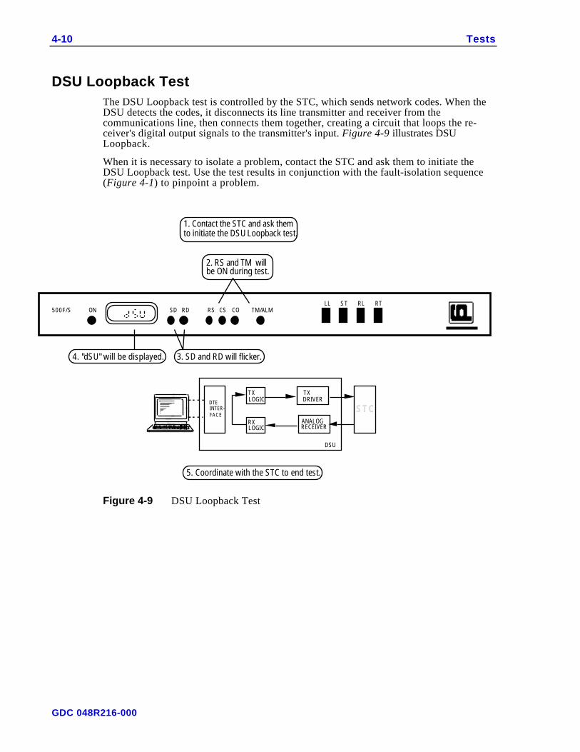
DSU Loopback TestThe DSU Loopback test is controlled by the STC, which sends network codes. When theDSU detects the codes, it disconnects its line transmitter and receiver from thecommunications line, then connects them together, creating a circuit that loops the re-ceiver's digital output signals to the transmitter's input. Figure 4-9 illustrates DSULoopback.
When it is necessary to isolate a problem, contact the STC and ask them to initiate theDSU Loopback test. Use the test results in conjunction with the fault-isolation sequence(Figure 4-1) to pinpoint a problem.
ON COLL ST
TM/ALMRL
RS CSRDSDRT
500F/S
2. RS and TM will be ON during test.
4. "dSU" will be displayed. 3. SD and RD will flicker.
DTEINTER-FACE
S T C
1. Contact the STC and ask them to initiate the DSU Loopback test.
5. Coordinate with the STC to end test.
TXLOGIC
RXLOGIC
DSU
TXDRIVER
ANALOGRECEIVER
Figure 4-9 DSU Loopback Test
GDC 048R216-000
A Technical Characteristics
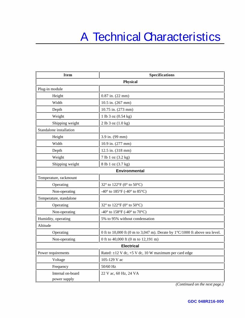
Item Specifications
Physical
Plug-in module
Height 0.87 in. (22 mm)
Width 10.5 in. (267 mm)
Depth 10.75 in. (273 mm)
Weight 1 Ib 3 oz (0.54 kg)
Shipping weight 2 Ib 3 oz (1.0 kg)
Standalone installation
Height 3.9 in. (99 mm)
Width 10.9 in. (277 mm)
Depth 12.5 in. (318 mm)
Weight 7 Ib 1 oz (3.2 kg)
Shipping weight 8 Ib 1 oz (3.7 kg)
Environmental
Temperature, rackmount
Operating 32° to 122°F (0° to 50°C)
Non-operating -40° to 185°F (-40° to 85°C)
Temperature, standalone
Operating 32° to 122°F (0° to 50°C)
Non-operating -40° to 158°F (-40° to 70°C)
Humidity, operating 5% to 95% without condensation
Altitude
Operating 0 ft to 10,000 ft (0 m to 3,047 m). Derate by 1°C/1000 ft above sea level.
Non-operating 0 ft to 40,000 ft (0 m to 12,191 m)
Electrical
Power requirements Rated: ±12 V dc, +5 V dc, 10 W maximum per card edge
Voltage 105-129 V ac
Frequency 50/60 Hz
Internal on-board
power supply
22 V ac, 60 Hz, 24 VA
(Continued on the next page.)
GDC 048R216-000

A-2 Technical Characteristics
Item Specifications
Electrical (Cont.)
Power dissipation
Standalone 8 W maximum
Rackmount 5 W maximum
Fusing
Plug-in module Two 1.5 A, 250 V, 3AG (GDC Part No. 215-150)
Enclosures See respective enclosures for fusing requirements
Safety protection UL listed and CSA approved
Compatibility Fully compliant with Bell Pub. 62310 and ANSI T1.410 standards
Operating mode
Conventional DDS Full-duplex, point-to-point/multipoint
64 kbps DDS Full-duplex, point-to-point
Data format
Asynchronous Binary, serial; 8-11 bits/character (ITU-T V.14 compliant)
Synchronous Binary, serial
Overspeed correction 1 or 2.3%
Data encoding Bipolar, return-to-zero
Data rate
Asynchronous 1.2,1.8, 2.4, 4.8, 9.6 or 19.2 kbps
Synchronous 2.4,4.8, 9.6,19.2, 56, 64 kbps
Line requirement Four-wire, non-loaded metallic circuit (19-26 ga)
Line impedance 135 ohms ±20% (nominal)
DTE interface EIA/TIA-232-E, ITU-T V.35, or optional EIA-530
Transmit power
2.4, 4.8,19.2, 56 and 64 kbps 6.0 dBm, maximum (50% duty cycle, random bipolar sequence, 135-ohm impedance)
9.6 kbps 0 dBm maximum (50% duty cycle, random bipolar sequence,
135- ohm impedance)
Sealing current 4 ma nominal
RTS-CTS delay
2.4 kbps 8 ms nominal
4.8 kbps 4 ms nominal
9.6 kbps 2 ms nominal
19.2 kbps 1 ms nominal
56 kbps 0.35 ms nominal
64 kbps Constant Carrier
Extended RTS-CTS delay 45 ms nominal(Continued on the next page.)
Item Specifications
GDC 048R216-000
Technical Characteristics A-3
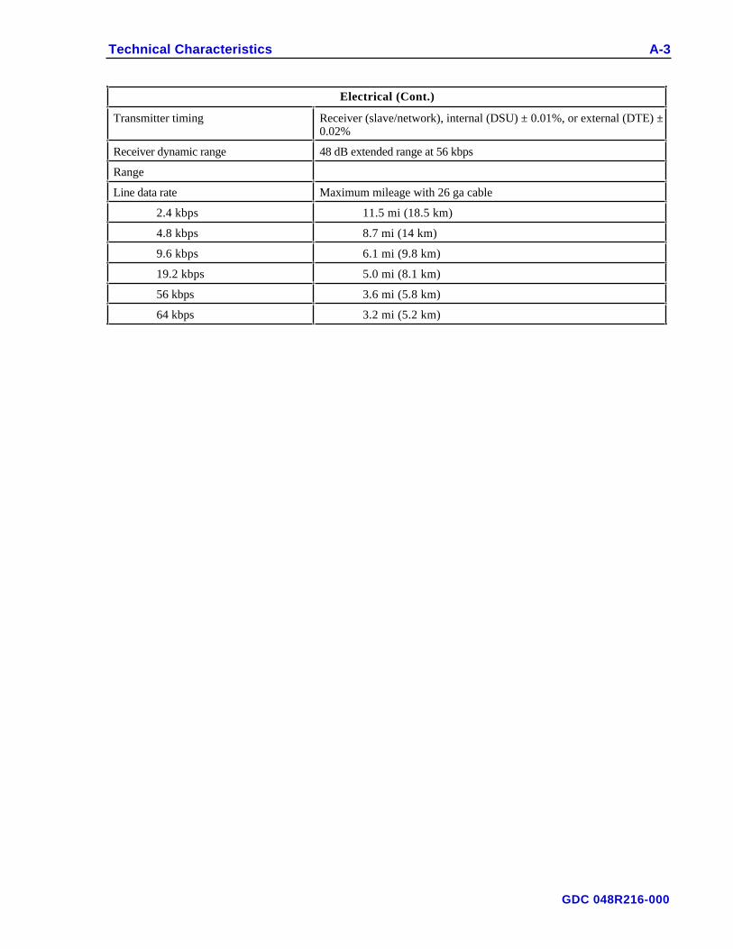
Electrical (Cont.)
Transmitter timing Receiver (slave/network), internal (DSU) ± 0.01%, or external (DTE) ±0.02%
Receiver dynamic range 48 dB extended range at 56 kbps
Range
Line data rate Maximum mileage with 26 ga cable
2.4 kbps 11.5 mi (18.5 km)
4.8 kbps 8.7 mi (14 km)
9.6 kbps 6.1 mi (9.8 km)
19.2 kbps 5.0 mi (8.1 km)
56 kbps 3.6 mi (5.8 km)
64 kbps 3.2 mi (5.2 km)
GDC 048R216-000
A-4 Technical Characteristics
Interface Signals (EIA/TIA-232-E)
Pin
No. EIA ITU-T DSU Name Description
2 BA 103 SD Transmitted data Transfers data signals from DTE for modulation andtransmission over communications line.
3 BB 104 RD Received data Transfers data signals to DTE that were received overcommunications line and demodulated by DSU.
4 CA 105 RS Request to send Indicates to DSU that DTE is prepared to transmit.
5 CB 106 CS Clear to send Indicates to DTE that DSU is prepared to transmit.
6 CC 107 DSR Data set ready Indicates to DTE that DSU is prepared for datacommunications.
7 AB 102 SIGGND
Signal ground Establishes a common ground reference for all interfacecircuits except protective ground.
8 CF 109 CO Received line signaldetector
Indicates to DTE that DSU is receiving data (notreceiving idle or OOS codes).
9 +12 V +12 volts +12 V supply
10 –12 V –12 volts –12 V supply
15 DB 114 SC Transmitter signalelement timing
Transfers transmitter signal timing information fromDSU to DTE.
17 DD 115 RC Receiver signal ele-ment timing
Transfers receiver signal timing information from DSUto DTE.
18 LL 141 ALE Analog Loopbackenable
Transfers signal from DTE to control analog loopbacktest if option switch S7-1 is ON.
20 CD 108/2 TR Data terminal ready Indicates to DSU that DTE is prepared for datacommunications.
21 RL 140 RLE Remote DigitalLoopback enable
Transfers signal from DTE to control Remote DigitalLoopback test mode if option switch S7-2 is ON.
24 DA 113 TC Transmitter signalelement timing(External Clock)
Transfers transmitter signal timing information fromDTE to DSU.
25 TM 142 TME Test mode indicator Indicates to DTE that DSU is in a test mode if optionswitch S7-3 is ON.
GDC 048R216-000

Technical Characteristics A-5
Interface Signals (ITU-T V.35)
V.35
Pin ITU-T EIA DSU Signal Description
B 102 AB Signal ground Establishes a common ground reference for all interfacecircuits except protective ground.
C 105 CA RS Request to send Indicates to DSU that DTE is prepared to transmit.
D 106 CB CS Clear to send Indicates to DTE that DSU is prepared to transmit.
E 107 CC DSR Data set ready Indicates to DTE that DSU is prepared for datacommunications.
F 109 CF CO Received line signaldetector
Indicates to DTE that DSU is receiving data (notreceiving idle or OOS codes).
K 142 TM TME Test mode indicator Indicates to DTE that DSU is in a test mode if optionswitch S7-3 is ON.
L 141 LL ALE Analog Loopbackenable
Transfers signal from DTE to control analog loopbacktest if option switch S7-1 is ON.
P
S
103
103
BA(A)
BA(B)
SD-A
SD-B
Transmitted data Transfers data signals from DTE for modulation andtransmission over communications line.
R
T
104
104
BB(A)
BB(B)
RD-A
RD-B
Received data Transfers data signals to DTE that were received overcommunications line and demodulated by DSU.
U
W
113
113
DA(A)
DA(B)
TT-A
TT-B
Transmitter signalelement timing(External Clock)
Transfers transmitter signal timing information fromDTE to DSU.
V
X
115
115
DD(A)
DD(B)
RT-A
RT-B
Receiver signal ele-ment timing
Transfers receiver signal timing information from DSUto DTE.
Y
AA/a
114
114
DB(A)
DB(B)
ST-A
ST-B
Transmitter signalelement timing
Transfers transmitter signal timing information fromDSU to DTE.
BB/b 140 RL RLE Remote DigitalLoopback enable
Transfers signal from DTE to control Remote DigitalLoopback test mode if option switch S7-2 is ON.
H 108/2 CD TR Data terminal ready Indicates to DSU that DTE is prepared for datacommunications.
GDC 048R216-000
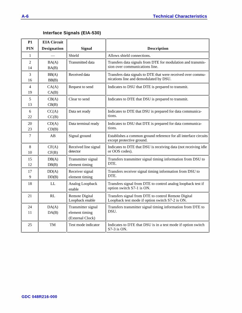
A-6 Technical Characteristics
Interface Signals (EIA-530)
P1
PIN
EIA Circuit
Designation Signal Description
1 — Shield Allows shield connections.
2
14
BA(A)
BA(B)
Transmitted data Transfers data signals from DTE for modulation and transmis-sion over communications line.
3
16
BB(A)
BB(B)
Received data Transfers data signals to DTE that were received over commu-nications line and demodulated by DSU.
4
19
CA(A)
CA(B)
Request to send Indicates to DSU that DTE is prepared to transmit.
5
13
CB(A)
CB(B)
Clear to send Indicates to DTE that DSU is prepared to transmit.
6
22
CC(A)
CC(B)
Data set ready Indicates to DTE that DSU is prepared for data communica-tions.
20
23
CD(A)
CD(B)
Data terminal ready Indicates to DSU that DTE is prepared for data communica-tions.
7 AB Signal ground Establishes a common ground reference for all interface circuitsexcept protective ground.
8
10
CF(A)
CF(B)
Received line signaldetector
Indicates to DTE that DSU is receiving data (not receiving idleor OOS codes).
15
12
DB(A)
DB(B)
Transmitter signal
element timing
Transfers transmitter signal timing information from DSU toDTE.
17
9
DD(A)
DD(B)
Receiver signal
element timing
Transfers receiver signal timing information from DSU toDTE.
18 LL Analog Loopback
enable
Transfers signal from DTE to control analog loopback test ifoption switch S7-1 is ON.
21 RL Remote DigitalLoopback enable
Transfers signal from DTE to control Remote DigitalLoopback test mode if option switch S7-2 is ON.
24
11
DA(A)
DA(B)
Transmitter signal
element timing
(External Clock)
Transfers transmitter signal timing information from DTE toDSU.
25 TM Test mode indicator Indicates to DTE that DSU is in a test mode if option switchS7-3 is ON.
GDC 048R216-000
Index
Analog Loopback test, option selection for DTE controlof, 2-6
Ground option selection, 2-6Installation
Anti-Streaming option selection, 2-8 checking the installation, 2-1Auto-Rate option selection, 2-7 procedures, 2-2Business equipment (DTE) rackmount, 2-2
ITU-T V.35 interface signals, Appendix C standalone, 2-2connections, 2-11 Line Data Rate option selection, 2-7EIA-530 interface signals, Appendix D Line Loopback Self-Test, 4-7EIA/TIA-232-E interface signals, Appendix B Line Loopback test, 4-4option selection for interface type, 2-6 Operation, 3-1ITU-T V.35 Optionsinterface signals, Appendix C checking option selection, 2-1option selection for interface type, 2-6 selection, 2-3, 2-6 — 2-10
Changes in service rate, 2-1 Overspeed option selection, 2-7Checking the installation and line, 2-1 Permanent RTS option selection, 2-6Circuit Assurance option selection, 2-9 Preoperational check, 2-1Communications line Rackmount shelf
checking the line, 2-1 electrical connections, 2-8connections, 2-11 installation, 2-2transposed lines, 2-2 operation, 3-1
CSU Loopback test, 4-10 Remote LoopbackCTS Delay option selection, 2-8 Inhibit option selection, 2-7Data mode (async/sync) option selection, 2-9 Methods option selection, 2-7Data Rate Adapter Card, 2-12 option selection for DTE control of, 2-5Description, 1-1 Self-Test, 4-7Diagnostics, 1-1 test, 4-4DSU Loopback test, 4-11 Timeout option selection, 2-7EIA-530 Remote Terminal test, 4-5
Interface Card, 2-12 Self-Test Pattern option selection, 2-6interface signals, Appendix D Self-Tests, 4-6option selection for interface type, 2-6 Service and training, 1-2
EIA/TIA-232-E 64K Scrambler option selection, 2-6interface signals, Appendix B Standalone enclosureoption selection for interface type, 2-6 electrical connections, 2-8
Electrical connections, 2-11 installation, 2-2End-to-End Self-Test, 4-9 operation, 3-1Features, 1-1 System Status option selection, 2-7Front panel Technical assistance procedure, 4-11
controls, 3-1 Technical characteristics, Appendix Aindicators, 3-1 Test Mode Indicator, option selection for DSU control
of, 2-5Inhibit option selection, 2-9
GDC 048R216-000
I-2 Index
TestsRemote Loopback Timeout option selection, 2-7Analog Loopback test, option selection for DTE
control of, 2-5 Remote Terminal test, 4-5Self-Test Pattern option selection, 2-6CSU Loopback test, 4-9Self-Tests, 4-6DSU Loopback test, 4-10Test Mode Indicator, option selection for DSUcontrol of, 2-5
End-to-End Self-Test, 4-8Line Loopback Self-Test, 4-6
Timing Source option selection, 2-6Line Loopback test, 4-3
Training, 4-12Remote Loopback Inhibit option selection, 2-7 Transmit Buffer Clock option selection, 2-6Remote Loopback Methods option selection, 2-7 Transposed lines, 2-1Remote Loopback Self-Test, 4-7 Unpacking and handling, 2-1Remote Loopback test, 4-4 Word Size option selection, 2-7Remote Loopback test, option selection for DTEcontrol of, 2-5
GDC 048R216-000


General DataComm, Inc.