bulletin h2-500f parker balston model h2-500 hydrogen ... · pdf filebulletin h2-500f parker...
TRANSCRIPT
Bulletin H2-500F Parker Balston Model H2-500 Hydrogen Generator
Parker Hannifin CorporationFiltration and Separation DivisionHaverhill, MA • 1-800-343-4048
1
®
General Description
WARNING: This product generates hydrogen gas. If hydrogen is contained and combined with oxygen and an ignition source, it can create an explosion. While normal use of this product would not create an explosion hazard, care must always be taken when using hydrogen. Failure to operate this product in accordance with instructions set forth in this manual can create a hazardous situation.
• Donotuseahydrogengasstoragevesselinconjunctionwiththehydrogengenera- tor. Stored quantities of hydrogen pose an explosion hazard.
• Normalprecautionsforanyhydrogensupplyshouldbetakenwhenusingthehydro- gen generator. DoNotuseiNasealeDoruNveNteDroom.
• DoNotuseaNoPeNFlameorotHeriGNitioNsourCeWitHiN10iNCHes (25cm)oFtHeoXYGeNveNt!
CautioN:tHisProDuCtissHelFliFeseNsitive.DoNotstoreFormoretHaN3moNtHsPriortoiNstallatioNaNDoPeratioN. Failure to follow this will cause the product to fail due to the drying of the membrane used for separation.
These instructions must be thoroughly read and understood before installing and operat-ingthisproduct.anymodificationoftheproductwillvoidthewarranty.Failuretooperatethisproductinaccordancewiththeinstructionssetforthinthismanualcouldjeopardizethe safety of the operator.
ifyouhaveanyquestionsorconcerns,pleasecalltechnicalservicesDepartmentat800-343-4048,8amto5Pmeasterntime(Northamericaonly).Forotherlocations,pleasecontactyourlocalrepresentative.sendemailto:[email protected].
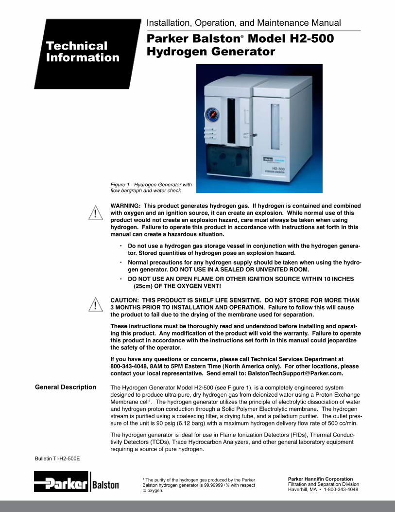
The Hydrogen Generator Model H2-500 (see Figure 1), is a completely engineered system designed to produce ultra-pure, dry hydrogen gas from deionized water using a Proton Exchange Membrane cell1 . The hydrogen generator utilizes the principle of electrolytic dissociation of water and hydrogen proton conduction through a Solid Polymer Electrolytic membrane. The hydrogen stream is purified using a coalescing filter, a drying tube, and a palladium purifier. The outlet pres-sure of the unit is 90 psig (6.12 barg) with a maximum hydrogen delivery flow rate of 500 cc/min.
The hydrogen generator is ideal for use in Flame Ionization Detectors (FIDs), Thermal Conduc-tivity Detectors (TCDs), Trace Hydrocarbon Analyzers, and other general laboratory equipment requiring a source of pure hydrogen.
1 The purity of the hydrogen gas produced by the Parker Balston hydrogen generator is 99.99999+% with respect to oxygen.
Figure 1 - Hydrogen Generator with flow bargraph and water check
Parker Balston® Model H2-500 Hydrogen Generator
Installation, Operation, and Maintenance Manual
Technical Information
Bulletin TI-H2-500E

Bulletin H2-500F Parker Balston Model H2-500 Hydrogen Generator
Parker Hannifin CorporationFiltration and Separation DivisionHaverhill, MA • 1-800-343-4048
2
NOTE: All installation, operation and maintenance activities for the hydrogen generators should be performed by suitable personnel using reasonable care.
The hydrogen generators are free-standing bench-top units.Donotsuspendthegeneratorfrom the wall or ceiling. Its weight and size could pose a falling hazard. The generator should be located indoors, protected from severe weather conditions, and free from excessive ambient dust or dirt. Donotinstallthegeneratoroutdoors.
The ambient temperature of the air surrounding the generator must be 60-90°F (16 - 32°C). Donot place the generator in an area where there is a chance of freezing. Place the hydrogen generator in an upright position, on a level surface, in close proximity to both the electrical power supply and the equipment requiring hydrogen.
Do not place generator over a source of heat, as this may cause the generator components to overheat. Maintain adequate airflow around the generator to reduce heat buildup. Do not block the vents located on the back and the left side of the hydrogen generator. Do not locate the gen-erator in a sealed or unvented room, or in close proximity to open flame or other ignition sources. Do not locate the generator where it will be subject to freezing temperatures. The generator is designed for indoor use only.
See Explanation of Symbols insert for a list of the symbols displayed on the generator and re-ferred to in this manual.
The hydrogen generator weighs 45 lbs (20 kg). Use proper equipment and lifting techniques for transporting this equipment to its installation location. The hydrogen generator is intended to re-main stationary when filled with water. If necessary, the generator may be transported over short distances when filled. Do not grasp the front panel when moving the generator, lift only from the bottom. Keep the generator in an upright position.
Remove all red tape from the top cover, the back panel, inside the water bottles, and on any other surfaces. Remove the red cap sealing the hydrogen outlet fitting and the bleed vent, on the back of the unit.
DeionizedWaterBags - Remove the deionizer bags from the plastic shipping container and inspect for holes or tears. Insert the “T” end of the plastic cable running through the deionizer bag into the hole of one of the water reservoir caps (see Figure 2). Pull the “T” end through the hole to the outside of the cap (see Figure 3). Repeat for the other cap. Do not let any foreign material fall into the water bottles. Insert one bag into each water reservoir.
Caution:Cellcontaminationisacumulativeandirreversibleprocess,whichwilleventual-lycauseanover-voltage,automaticallyshuttingdownthegenerator.thedeionizerbagsareforafinaldecontaminationstageandshouldnotbeusedtopurifylowgradewater.
Power - The hydrogen generator may be operated by a 100-120 / 200 -240 VAC, 50-60 Hz single phase power supply (check the product label on the generator for specific generator volt-age). To connect the generator to the power supply, simply plug the female end of the electrical cord into the receptacle on the back of the generator, and the opposite end into a three-pronged grounded power receptacle.
DeionizedWater - The hydrogen generator must be supplied with deionized water with a minimum resistivity of 5 Meg-Ohm/cm. Parker Hannifin provides a point of use accessory, the HydroGen™ Mate (P/N 72-230) that provides high purity water (>5 Meg-Ohm/cm) from tap water for manually filling the generator.
General
Transporting
Preparation
Utilities
Symbols
Installation
The H2-500 Hydrogen Generator is certified to the electrical safety requirements as specified by the IEC, CSA, and UL standards. This unit bears the CSA marking on the product label. Product supplied to Europe carries the CE mark (230 VAC units only). The generator complies with EMC standards.

Bulletin H2-500F Parker Balston Model H2-500 Hydrogen Generator
Parker Hannifin CorporationFiltration and Separation DivisionHaverhill, MA • 1-800-343-4048
3
Piping - The outlet connection for the hydrogen generator is a 1/8” compression fitting, the bleed port is 1/8” compression, and the relief port is 1/4” NPT. All tubing and fittings downstream from the hydrogen generator should be clean stainless steel to minimize contamination of the hydrogen stream. If copper tubing has been used with hydrogen in the past and has yielded ac-ceptable results, there is no need to alter an existing piping configuration to install the hydrogen generator.
Caution: If you pipe the gas away from the bleed port, the tubing must angle downward to avoid water condensing in the line and plugging the vent to the purifier. Also, the bleed line must vent to atmosphere to avoid introducing back pressure on the cell.
Pressureregulator – The pressure is controlled using the Pressureregulator located on the front panel, exposed when opening the front gray panel door (see Figure 4). The pressure can be monitored using the gauge located on the front of the unit. There is a Pressurerelief valve inside the generator that is set for 125 psig (8.6 barg) in case of internal pressure build up. The expelled gas is channeled through the Pressure Relief Port located on the back of the unit.
(Note: the generator pressure regulator is pre-set to deliver hydrogen at 90 psig.)
shutoffvalve – The generator includes a shutoff valve located on the front panel behind the gray door (see Figure 4). Use this valve to shut the unit off when not in use. In case of extended periods of downtime see the Operation / Shutdown / Storage sections.
Figure 2 - Insert the “T” end of the deionzer bag through the bottom of the water bottle cap.
Figure 3 - Pull the “T” through to the top of the cap.
Figure 4 - Control and Fault Indicator lights located behind the front gray panel.
HIGH HYDROGEN FLOW INDICATOR
CHANGE WATERINDICATOR
LOW WATER INDICATOR
STARTBUTTON
PRESSUREREGULATOR
H2 FLOWSHUTOFFVALVE(CLOSED)
WATERDRAINPORT

Bulletin H2-500F Parker Balston Model H2-500 Hydrogen Generator
Parker Hannifin CorporationFiltration and Separation DivisionHaverhill, MA • 1-800-343-4048
4
Water Reservoir
Startup
After carefully following all the preparation procedures in the Installation section, open the top panel and remove the water reservoir caps (with the deionizer bags already attached). Fill both reservoirs with deionized water until the level in the tank reaches the “Full” mark. It will take approximately 3 liters of deionized water to fill the generator. Donotoverfillthewaterbottles.
Insert the drain tube fitting (with drain tube attached) into the drain port and remove approximately 100 ml of water (see Figures 5, 6).
Make sure that the deionizer bags are fully immersed in the water and that they do not block the outlet port on the bottom. Do not block the small vent hole in the water reservoir cap with the “T” fitting or any-thing else. Be sure to remove all of the red tape that was applied to the unit for shipping purposes. Donot let the deionizer bags dry out.
Note: The generator will automatically shut down if the water level becomes too low, or the water quality is not sufficient.
Open the gray panel door on the front of the generator to expose the generator controls (See Figure 4). Turn the shutoffvalve to the closed position. Connect the electrical power cord to the power receptacle on the back left side of the generator, and connect the other end to the wall receptacle.1 If the line needs to be purged before the hydrogen can be used in the instrument, make sure a
3-way valve is in the line near to the instrument.Note: The recommended 3-way valve is Parker 2F-HB4X-K-SSP
2 Make sure all the gas connections are secure.3 Set the Pressure Regulator (see Figure 4) to minimal pressure by turning the knob counter clock-
wise until the knob moves out approximately 1/2” from the front panel.4 Turn on the Powerswitch located on the power receptacle on the back. The Power and the No
Hydrogen Flow indicators should illuminate on the front panel (see Figure 7). DoNotPresstHestartButtoN.
Note: Except when the unit requires servicing, keep the Power Switch on, to prevent damage to the puri-fier.
5 The unit must warm up for at least one full hour or damage will occur. The unit will beep once every 60 seconds to let you know that there is no flow being produced.
6 After the minimum one hour warm up, press the Start button located on the front panel (see Fig-ure 4). TheHydrogenFlow and the HighHydrogenFlow indicators should now be illuminated. The bargraph will also illuminate, from zero to maximum. The NoHydrogenFlow indicator will be off. Do not open the outlet valve until the bargraph has illuminated to maximum and started to de-cline. This indicates that the internal system pressure is sufficient to provide the required hydrogen flow.
Note: The High Hydrogen Flow light comes on when the generator is operating at the maximum flow rate. During normal operation the indicator will be illuminated as the generator builds up pressure when you first start the system or when you are running at or near the maximum capacity of the generator. If the system senses that the pressure is not increasing at the internally preset rate or is actually decreas-ing, the unit will assume abnormal conditions are present and automatically shut the unit down. If the unit shuts down, press the start button to try to re-initiate flow. If this is not effective, then proceed to the Mass Leak section for instructions.
7 Slowly open the Outlet Valve.Note: The pressure will drop initially then begin to increase as the volume downstream begins to fill. The High Hydrogen Flow light will be illuminated. If the volume is so large that the system is unable to main-tain a preset filling rate then the Mass Leak error condition is reached and the unit will automatically shut down. See Mass Leak section for instructions.
Operation

Bulletin H2-500F Parker Balston Model H2-500 Hydrogen Generator
Parker Hannifin CorporationFiltration and Separation DivisionHaverhill, MA • 1-800-343-4048
5
Mass Leak Follow the instructions listed in the Initial Startup section. If the pressure continues to drop, the HighHydrogenFlow (Mass Leak) light will illuminate (see Figure 4) and the generator will shut down. A Mass Leak may be caused by a leak in the piping to the downstream equipment, or it may be caused by the downstream piping volume being too large for the generator to fill. If it is determined that a Mass Leak is present, please follow the procedure below:
1 Close the shutoffvalve(see Figure 4, shown in the CLOSED position).2 Press the Start switch to reset the Mass Leak detector which is indicated by the HighHydro-
gen Flow indicator light turning off (see Figure 4).3 Re-pressurize the generator. 4 Repeat the Initial Startup procedure three times to verify the leak.
If the system continues to detect a leak, check all the external tubing connections and make sure that the volume is not too large for the generator purchased (500 cc/min). If the leak still persists, check the fittings inside the generator.
Caution: Donotusecommercialleakdetectionfluidsonanylexan® plastic parts in the generator. These fluids may cause cracking and crazing which leads to part failure. Use a solu-tion of 4-5 ml of liquid dish soap in one liter of water.
Caution: useextremecarewhencheckingforinternalleaks. Due to the nature of the gases involved use a protective face shield or other appropriate equipment whenever servicing or trouble-shooting the generator with the cover removed.
8 Purging - If you have installed a 3-way valve in the line and want to purge the lines, first turn the 3-way valve to the closed position to pressurize the lines. Next turn the valve to the vent position and vent the hydrogen gas for 2 minutes. Repeat the pressurization / purge routine at least 5 times.
Note: Make sure that flow rate out the vent port is less than 500 cc/min to avoid shutting the unit down. Use a needle valve or other flow restrictor on the vent.
9 Flowing- Turn the 3-way valve to the instrument flow direction. Adjust the flow controller on the instrument until desired flow rate is reached, with a maximum of 500 cc/min.

Bulletin H2-500F Parker Balston Model H2-500 Hydrogen Generator
Parker Hannifin CorporationFiltration and Separation DivisionHaverhill, MA • 1-800-343-4048
6
To maintain the highest purity, the hydrogen generator should be run continuously. Monitor the hydrogen consumption of the downstream equipment to ensure flow is within the capacity of the generator (500 cc/min.). Both the Powerindicatorlight and the HydrogenFlow Indicator light should be illuminated (see Explanation of Symbols at the back of the manual).
The water level should be monitored regularly and refilled as necessary. The reservoirs hold enough water for at least 3 days of continuous operation (3 liters total). Water can be added by re-moving the cap of the water reservoir (do not pull the deionizer bag out) and adding enough water to reach the Full mark on the front view port. Replace the cap, and make sure the deionizer bag does not block any of the ports.
To maintain the integrity of the hydrogen cell, follow the guidelines listed below:
• Keep a supply of deionized water in the reservoir above the Refill line at all times.• Minimize the “dead - volume” in the piping between the generator and the downstream equip-
ment.• Never expose the unit to temperatures below freezing.• Never abruptly open the shutoffvalve to large volumes. The large hydrogen demand can trig-
ger the Mass Leak safety feature.If the built-in diagnostics trigger a fault LED to illuminate, consult the Troubleshooting section of this manual for further instructions.
Operation
Operational Summary
Warning: Under no circumstances should the generator be operated with the cover removed.
Caution: Long periods of unattended operation are possible, provided that an adequate water sup-ply is maintained. If more than 6 hours of standby service is anticipated, close the Shutoff Valve.
Note: To prolong the life of the purifier assembly, maintain power to the system unless extended periods of non-use are expected.

Bulletin H2-500F Parker Balston Model H2-500 Hydrogen Generator
Parker Hannifin CorporationFiltration and Separation DivisionHaverhill, MA • 1-800-343-4048
7
Shipping
Figure 6 - To remove the Drain Port Insert, press down on the metal clip to release the insert, and pull.
Figure 5 - Insert the Drain Port Insert along with a length of tubing into the Drain Port in the Front
1 Turn the Pressureregulator counter-clockwise until the knob is about 1/2” from the front panel (see Figure 4). Leave the shutoffvalve open and wait until the outlet pressure gauge reads zero.
2 Shut the power off. Allow the generator to cool for a minimum of 4 hours.3 Drain the water from the water reservoirs using the Drain Port Insert Kit. Connect a length of
tubing to the drain port inset fitting, and connect the fitting to the generator at the drain port. The drain port is located on the front gray panel behind the gray door (see Figure 5).
4 Press down on the metal tab on the top of the DrainPort connector to remove the Drain Port insert and tube after the unit has been drained (see Figure 6).
5 Place a piece of tape over the vent holes in the water bottles cap.6 Pack the generator carefully in the original packing box or request new packaging from Park-
er Hannifin. Be sure to display the RA number on the outside of the box for prompt response.7 In order to maintain the warranty on the generator, ship the generator in a manner that will
preventfreezing. Freezing temperatures will cause irreparable damage to the hydrogen cell assembly.
Shutdown
Storage
If the unit is to be idle for a few months or more, the generator should be turned off and the inter-nal pressure vented.
To store the unit:1 Turn the Pressureregulator counter-clockwise until the knob is about 1/2” from the front
panel (see Figure 4). Wait until the outlet pressure gauge reads zero.2 Shut the Power OFF. Leave the generator connected to the downstream equipment or
switch the 3-way valve (if installed) to VENT.3 Fill the tanks at least half full with deionized water. Make sure that the cell has at least 2”
(5 cm) of water showing in the cell assembly tube. This can be viewed from the vent holes in the back of the generator.
4 Check the water level in the hydrogen cell assembly every 6 months to maintain the 2” (5cm) water height.
If the generator is being returned to the factory for repair, contact the Technical Support Services Department at 800-343-4048 for a Return Authorization (RA) number and new packaging if the original is no longer available.

Bulletin H2-500F Parker Balston Model H2-500 Hydrogen Generator
Parker Hannifin CorporationFiltration and Separation DivisionHaverhill, MA • 1-800-343-4048
8
Water Quality Indicators
Hydrogen Flow Indicators
The Parker Balston Model H2-500 hydrogen generator has built-in system diagnostics to monitor the operation of the generator and alert the operator in case of a failure. There is a Powerindica-tor light on the front panel of the generator to signal the operational status of the system (see Figure 7).
The ControlCircuitry controls the membrane cell current to a safe level and eliminates the pos-sibility of excessive hydrogen production. If a fault occurs and an indicator is illuminated, follow the instructions in the Troubleshooting section to clear the fault.
The hydrogen generator has a BarGraph that is used to check the hydrogen flow (Flow Check) and the water quality (Water Check) (see Figure 7).
Note: See the Explanation of Symbols section at the back of the manual to match the symbols on the generator to the descriptions listed below.
HydrogenFlowindicator - The Hydrogen Flow Indicator illuminates to indicate the cell is gener-ating hydrogen (see Figure 7).
FlowCheckBarGraph - In normal operating mode (the side Mode Button is out), the bar graph displays the percentage of flow produced by the system (see Figure 7). The Bar Graph feature displays the flow from High (500cc/min) to Low (less than 5 cc/min).
NoHydrogenFlowindicator - The NoHydrogenFlowindicator illuminates when the gen-erator is no longer producing hydrogen (see Figure 7). An audible alarm will sound once every 60 seconds to alert the user that no hydrogen is being produced.
HighHydrogenFlowindicator(massleak)-The High Hydrogen Flow Indicator illuminates when the generator is operating at the maximum flow rate (see Figure 4). During normal opera-tion the indicator will be illuminated as the generator builds up pressure when you first start the system or when you are running at or near the maximum capacity of the generator. If the demand on the unit exceeds capacity then the generator will shut down and the NoHydrogenFlowindi-cator will illuminate and begin to beep. This may be caused either from a leak in the piping to the equipment or it may indicate the volume being filled is too large for the generator (see Mass Leak section). The unit must be reset with the Start button once the leak has been found.
WaterCheckBarGraph- If the Mode Button is pressed in, the Bar Graph will display the Water Check quality (see Figure 7). The Bar Graph indicates the water quality level from High (>5 Meg-Ohm/cm) to Low. This quality level corresponds to the changes in the current going through the water.
ChangeWaterindicator - If the water quality in the reservoir reaches the Low level, the Change Water Indicator (see Figure 4) will illuminate and the unit will shut down. The water in the unit and the deionizer bags must be replaced.
lowWaterindicator - If the water level drops too low in the water reservoir, the generator will stop producing hydrogen. Refill the water bottles to the full line and press Start to begin the flow of hydrogen.
DiagnosticsGeneral

Bulletin H2-500F Parker Balston Model H2-500 Hydrogen Generator
Parker Hannifin CorporationFiltration and Separation DivisionHaverhill, MA • 1-800-343-4048
9
General
Water Refill
Whenperformingroutinemaintenance,carefullyfollowtheinstructionsprovidedinthissectiontoavoidinjuryordamage.serviceshouldbeperformedbypersonsfamiliarwiththeserviceandsafetyrequirementsofelectromechanical/electrochemicaldevices.
With proper care and maintenance the hydrogen generator will provide years of trouble-free op-eration. Only routine service is needed to maintain peak operational conditions.
The primary maintenance tasks required by the hydrogen generator are replacing the deionizer bags (approximately every 6 months), and refilling the water reservoirs (every 3 days). A summary of replacement part numbers and recommended service frequency is shown at the end of this section.
Donotusewater,aerosols,orothercleaningagentsontheunit. If necessary, the generator can be wiped down with a clean dry cloth on an as needed basis. Use of any liquid detergent to clean the generator could present an electrical hazard.
Donotusecommercialleakdetectionfluidsonanylexan® plastic parts in the generator. These fluids may cause cracking and crazing which leads to part failure. Use a solution of 4-5 ml of liquid dish soap in one liter of water.
Refill the water in the generator whenever the water level reaches the refill level displayed on the front panel (see Figure 7). The water supply should last approximately 3 days when the reservoirs are filled to the Full level (They hold 3 liters approximately of water).
If the lowWater indicator (see Figure 4) should illuminate, the generator will stop producing hydrogen to safeguard the hydrogen cell from permanent damage. If this happens, close the shutoff valve. Add water to the generator until the Full level is reached and press the Start switch to begin generating hydrogen and building pressure after operational pressure is obtained, slowly open the shutoff valve.
Figure 7 - Diagnostic Indicators.
Maintenance
PRESSURE GAUGE
POWERINDICATOR
HYDROGEN FLOW
NO HYDROGEN FLOW
BAR GRAPH
MODE BUTTON
WATERREFILL LEVEL
WATER FULL LEVEL

Bulletin H2-500F Parker Balston Model H2-500 Hydrogen Generator
Parker Hannifin CorporationFiltration and Separation DivisionHaverhill, MA • 1-800-343-4048
10
Description P/N Frequency
Replacement Deionizer Bags 7601132 6 Months
Replacement Main Fuse (100V or 120V) A03-0066 As Needed
Replacement Main Fuse (220V) 13216 As Needed
Replacement Transformer Fuse (all voltages) B02-0203 As Needed
Replacement Parts
Fuse Replacement Occasionally, the fuses in the hydrogen generator may burn out. The main fuses are located in the power receptacle on the back side of the generator. The transformer fuses are located just below the power receptacle. Beforeservicingthefuses,turnthegeneratoroffanddisconnectthepower cord from both the power supply and the generator power receptacle.
To access the main fuses, use a small screwdriver to remove the fuse holder located in the back of the generator and in the power receptacle. Replace with the appropriate fuse and re-assemble. To access the transformer fuses, use a small screwdriver, press in and rotate one quarter turn, and remove the fuse. Replace with the appropriate fuse and reassemble.
To maintain the safety and performance integrity of the product, use only the fuse of the size and type detailed in the Specifications, Parts, and Accessories sections of this bulletin.
Deionizer BagReplacement
The water reservoirs should be rinsed and the deionizer bags replaced every six months, or whenever the ChangeWater light illuminates (see Figure 4). No tools are necessary to change the deionizer bags.
1 Turn the Powerswitch to OFF and make sure the shutoffvalve is in the OPEN position (see Figure 4) in order to vent the hydrogen from the generator.
2 Lift the top cover and unscrew the water reservoir caps. Lift the deionizer bag out of the reservoir along with the cap. Disconnect the deionizer bags from the caps and discard.
3 Inspect the new deionizer bags (P/N 7601132) for holes or tears. (Contact Parker for re-placement if damaged.) Insert the “T” end into the cap until it secures the bag to the cap (see Figures 2 and 3). Repeat for second bag.
1 Follow instructions for deionizer bag replacement then continue on.2 Use the drain port insert with the 1/4” tube connected to it to drain the water reservoirs.
There is approximately 3 liters of water in the generator when full. Connect the insert to the DrainPort located on the front panel behind the gray door (see Figure 4) and drain the unit (see Figure 5).
3 Remove the drain port insert by pressing down on the metal tab and pulling the fitting out (see Figure 6). Next refill the reservoirs with deionized water. Repeat steps 2 and 3 several times.
4 Finally, remove the drain port insert and fill the reservoirs completely with approximately 3 liters of deionized water.
5 Replace the caps with the new deionizer bags attached, being careful to avoid blocking any of the ports in the generator.
Note: Do not allow the deionizer bags to dry out, they must be immersed in water to perform.
6 Start the generator in the same manner found in the Startup section.
Change Water
Note: To ensure consistent product performance and reliability use only genuine Balston replacement parts and filter cartridges.

Bulletin H2-500F Parker Balston Model H2-500 Hydrogen Generator
Parker Hannifin CorporationFiltration and Separation DivisionHaverhill, MA • 1-800-343-4048
11
Hydrogen Purity (1) 99.99999%
CSA Safety Standard CAN/CSA 22.2 No. 1010.1- 92
IEC 1010 Safety Standard IEC1010-1:1990+A1 1992+A2:1995/EN61010-1:1993
IEC 1010 Installation Category II, Pollution Degree 2
UL Safety Standard UL 3101-1, First Edition
EMC Compliance CISPR11:1190/EN55011:1991/EN50082-1:1997/ EN61326-1 (1997)
Maximum Flow Rate (@100 psig/7 barg) 500cc/min.
Outlet Pressure 0-90 psig (0-6.12 barg)
Hydrogen Outlet Port 1/8” Compression
Hydrogen Bleed Port 1/4” Compression
Hydrogen Relief Port 1/4” Female NPT
Water Requirements DeionizedWater(ž5Meg-Ohm/cm)
Maximum Ambient Relative Humidity 80%(IndoorUseOnly)
Min/Max Ambient Temperature 60/90°F (16/32°C)
Electrical Requirements (2) 100-120/200-240 VAC, 47-63 Hz
Power Consumption 650 Watts@ 120 VAC / 575 Watts @ 220 VAC
Main Fuse 100 VAC, 120 VAC 6.3 Amp SB 5x20 GDC
Main Fuse 220 VAC 3.15 Amp SB 5x20 GDC
Transformer Fuse (all voltages) 0.63 Amp SB 5x20 GDC
Product Dimensions 13”h x 15”w x 18”d (33cm x 38cm x 43cm)
Product Weight/Shipping Weight 45 lbs./51 lbs. (20 kg / 23 kg)
System Specifications
Don’t Forget To:
Serial Numbers
1 To activate your warranty go to www.labgasgenerators.com/warrantyregistrations.
2 Keep your product certification in a safe place.3 Call the Technical Services Department at 800-343-4048,8AM to 5PM Eastern Time with any questions (North America only). Send email to: [email protected]. For other locations, please contact your local representative.
The serial number for the unit is located on the back of the unit. For your own records, and in case service is required, please record the following:
DATE IN SERVICE SERIAL NO.
Pleasehavetheserialnumberavailablewhencallingforassistance.
Notes:
1 The purity of the hydrogen gas produced by the Parker Balston Hydrogen Generator is 99.99999+% with respect to oxygen.
2 Main power supply must be between 95
Description P/N
HydroGen™ Mate 72-230
Optional Accessories
VAC and 250 VAC and 47-63 Hz.

Bulletin H2-500F Parker Balston Model H2-500 Hydrogen Generator
Parker Hannifin CorporationFiltration and Separation DivisionHaverhill, MA • 1-800-343-4048
12
No Power
Symptom Course of Action
alltroubleshootingactivitiesshouldbeperformedbysuitablepersonnelusingrea-sonable care.
Warning:anytroubleshootingorserviceactivitywhichrequiresremovalofthegen-eratorcovershouldbedoneusingextremecaution.exposedaCmaybepresent.
Refill Water Indicator Light Illuminated
Change Water Indicator Light Illuminated
Low Output Pressure
High Hydrogen Flow Indicator Light Illuminated Unit shuts down
No Hydrogen Delivered
Moisture at Bleed Outlet
Notes 1 To arrange for system service, contact the Technical Services Department at 800-343-4048, 8AM to 5PM Eastern Time. For other locations, please contact your local representative. Send email to: [email protected].
Check power source and connections to the power source.
Check terminal connections and power cord.
Check power source fuses.
Check generator fuses.
Completely fill water reservoir with deionized water and press the Start button on the front panel.
Water reservoir ports are blocked by the deionizer bags or other debris. Remove obstruction.
Consult Factory if light does not go off. (1)
Water Quality is bad, see Maintenance section for draining and rinsing procedure.
Hydrogen demand exceeds generator capacity. Check capacity of equipment and piping downstream and install a flow control device.
Check external system piping for leaks.
Check internal system piping for leaks.
Flow is at or near maximum rating of 500 cc/min.
Onstartup,lightisilluminatedasthecellisworkingatfullcapacity.
In both cases there is no problem unless unit shuts down, if that occurs then see the next listing for instructions.
Mass Leak detected in system. Check external piping for leaks.
Hydrogen demand exceeds generator capacity. Check capacity of equipment and piping downstream and install a flow control device.Check internal system for piping leaks.
Check power connections (see above).
Check water level. Generator will shut down if water level is below the Low Level.
Shutoff valve is closed; open Shutoff valve.
Attempted to start generator before purifier reached working temperatures.
Check piping for leaks.
Consult factory.(1)
Bad purifier or heater. Consult factory. (1)
Back pressure in the purifier bleed outlet tubing; check the angle of the bleed outlet - make sure it angles downward.
Make sure bleed outlet is venting properly.
WARRANTy (NORTH AMERICA ONLy)(FOR INFORMATION CONTACT yOUR LOCAL REPRESENTATIVE)
Parker Hannifin guarantees to the original purchaser of this product, that if the product fails or is defective within 12 months from the date of purchase, when this product is operated and maintained according to the instructions provided with the product, then Parker guarantees, at Parker’s option, to replace the product, repair the product, or refund the original price for the product. This warranty applies only to defects in material or workmanship and does not cover: ring and valve wear on compressors, routine maintenance recommended by the instruc-tions provided with this product, or filter cartridges. Any modification of the product without written approval from Parker will result in voiding this warranty. Complete details of the warranty are available on request. This warranty applies to units purchased and operated in North America.
Troubleshooting
High Hydrogen Flow Indicator Light Illuminated
Unit still running

Bulletin H2-500F Parker Balston Model H2-500 Hydrogen Generator
Parker Hannifin CorporationFiltration and Separation DivisionHaverhill, MA • 1-800-343-4048
13
Symbol Description
POWER INDICATOR
HYDROGEN FLOW INDICATOR
NO HYDROGEN FLOW INDICATOR
MAXIMUM HYDROGEN FLOW or EXCESSIVE FLOW RATE INDICATOR (MASS LEAK)
CHANGE WATER INDICATOR
LOW WATER INDICATOR
HYDROGEN FLOW START BUTTON
FULL WATER TANK INDICATOR
REFILL WATER TANK INDICATOR
WATER DRAIN PORT
The symbols listed below are found on the front panel of the Hydrogen Generator.
Explanation of Symbols

Bulletin H2-500F Parker Balston Model H2-500 Hydrogen Generator
Parker Hannifin CorporationFiltration and Separation DivisionHaverhill, MA • 1-800-343-4048
14
Symbol Description
Caution, refer to accompanying documents for explanation.
Refer to the caution/warning note indicated for explanation.
Caution, risk of electric shock.
3
explanationofWarningsymbols
©Parker Hannifin Corporation 2001, 2008 Printed in U.S.A. Bulletin TI-H2-500F
Parker Hannifin (UK) LtdIndustrial DivisionSuite 42, Kent House, Romney PlaceMaidstone, Kent ME15 6LH United KingdomTel: +44 (0)1622 772440 Fax: +44 (0)1622 772446www.parker.com\pag
Parker Hannifin CorporationFiltration and Separation Division242 Neck RoadHaverhill, MA 01835Tel: 978-858-0505 Fax: 978-556-7501www.labgasgenerators.com