operating manual - wagner werkzeugsysteme müller gmbh · 2 operating manual rs10-fl contents 1 ......
TRANSCRIPT
Operating Manual
Thread Rolling Head RS10-FLArticle No. 74878500

2 Operating Manual RS10-FL
Contents
1. Preface 3
2. Safety Instructions 5
3. Standard Equipment 6
4. Rolling Head 74.1 Main components 74.2 Function 74.3 Applications 7
5. Roll holders 8
6. Thread rolls 96.1 Inscription 96.2 Bearings 106.3 Quality 10
7. Preparation for thread rolling 117.1 Thread Rolling Head 117.1.1. Assembly of the thread rolls 117.1.2. Assembly of the roll holders 127.1.3. Adjustment of the thread diameter 137.1.4. Adjustment of the thread length 137.2 Workpiece / machine 137.2.1. Rollable materials 137.2.2. Premachining of the workpiece 147.2.3. Rolling threads up to shoulders 157.2.4. Thread runout 157.2.5. Feed for thread rolling 157.3 Rolling speed 167.4 Power output requirement 167.5 Coolant/ lubricant 177.6 Tool life 17
8. Mounting on the machine 18
9. Trouble shooting 199.1 Faults in equipment and assembly errors 199.2 Defects in the rolled thread 22
10. Care and Maintenance 2410.1 Maintenance intervals 2410.2 Disassembly of the rolling head 2410.3 Reassembly of the rolling head 25
11. Dimensions 2611.1 Rolling head RS10-FL 2611.2 Closing ring 2611.3 Shanks 27
12. Spare Parts 2812.1 Thread rolling head RS10-FL 2812.2 Exploded drawing 2912.3 Installation drawing 3012.4 Shanks and relative internal stops 31
13. Roll holder table RA10-FL 32

Operating Manual RS10-FL 3
Preface
1. Preface
You bought a high-quality commodity, which facilitates effective and economic ope-ration. Our Thread Rolling Heads are known for their high quality and long-life cycle. We hope that you are fully satisfied with our products. This manual is made to help you taking the first steps with your new WAGNER® pro-duct, explain the operation and point out possible hazards.
After Sales ServiceIf you need further advice, training or ulterior help or if you are not satisfied with your WAGNER® product, please contact us! Our sales team is at your disposal.
The contents of this manual should be read, understood and followed in every aspect by everybody involved. This is especially true for the safety instructions and notes on hazards found throughout this manual (see chapter 2 Safety Instructions).Following these instructions will help avoid accidents, mistakes and malfunctioning. This documentation includes all information necessary for using and maintaining your WAGNER® Thread Rolling Head. The documents are up-to-date at the time the product was manufactured.
Use only these documents when working with the Thread Rolling Head.WAGNER® WERKZEUGSYSTEME MÜLLER GmbH reserves the right to make technical changes to improve the product, if and when appropriate.If the instructions in this manual are not followed, and this negligence results in mis-takes, damages, loss of production, etc., WAGNER® WERKZEUGSYSTEME MÜLLER GmbH will not be responsible for any subsequent damages.Due to copyrights, we must point out that this manual is for internal use only. Provi-ding this manual to third parties is prohibited.
During operation, maintenance and repair the respective national and international »regulations for the prevention of industrial accidents« apply in addition to the pre-viously listed instructions. The operating instructions, particularly the chapter »Safety instructions«, have to be read in any case. Following the safety instructions and legal regulations helps to prevent doing damage to persons, machines and our product.
WarrantyIn case of buying and using original WAGNER® spare parts and accessories, we gu-arantee proper operation of the Thread Rolling Head.
We exclude any warranty for damage of persons, machines and our products, in case of:• improper mounting and operating • using no original spare parts • removing components and assemblies • arbitrarily modifying our products • using broken rolling heads.
PLEASE NOTE:Read this operating ma-nual carefully before initial operation and take note of the hazard warnings!

4 Operating Manual RS10-FL
Preface
When using accessories which are not made by WAGNER® or explicitly approved by us, we exclude any warranty.Generally, we are not liable for damages of all kind caused by removing safety equipment on the machine. We imply that our products are only set up on technically proper operating machines.
CAUTION: Do not use this product for any other purpose than its designated use! Follow the »safety instructions and notes on hazards«! This product should only be used by trained specialists; otherwise its use may constitute a risk to life and limb of the user and cause damage to material property. For such cases, the manufacturer declines all responsibility.
Do not use force when mounting, demounting and operating. You could otherwise damage the rolling head or the machine.
Initial operationPlease carry out an operational check before initial operation of the Thread Rolling Head.
Operating Manual RS10-FL 5
Safety Instructions
2. Safety Instructions
Persons in charge of operating, maintaining and repairing always have to read and understand the manual and the safety instructions. People who are under the influ-ence of alcohol and/ or drugs may cause accidents!
When mounting, please bear in mind the weight of the thread rolling attachment and, if necessary, lift by means of a lifting equipment.
Take care that the cutting sides between the attachment and the machine are clean. Dirt may affect the precision of the workpiece.
Generally, shut down the machine at the main switch when mounting the attachment. Make sure that the spindle cannot start unexpectedly when exchanging the rolls.
Remove all tools and inspection equipments from the working chamber of the ma-chine before setting into operation. There is a risk of injury by centrifuging tools and equipment!
Close the safety gate or protection cover before operating! Hurtling chips and broken heads or work pieces may cause damage to people and machines.
Make sure that the Thread Rolling Head cannot disengage during operation.
When closing the Thread Rolling Head do not touch the head, do not touch rotating tools: risk of injury!
Please check and handle the thread rolls extremely carefully. The rolls have square edges. If necessary, wear safety gloves!
Please make sure the Thread Rolling Head is protected and fastened appropriately when transporting.
6 Operating Manual RS10-FL
Standard Equipment
3. Standard Equipment
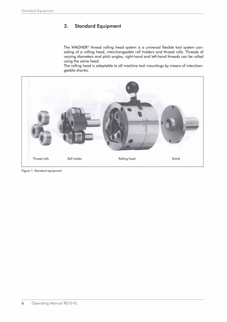
The WAGNER® thread rolling head system is a universal flexible tool system con-sisting of a rolling head, interchangeable roll holders and thread rolls. Threads of varying diameters and pitch angles, right-hand and left-hand threads can be rolled using the same head. The rolling head is adaptable to all machine tool mountings by means of interchan-geable shanks.
Figure 1: Standard equipment
Thread rolls Roll holder Rolling head Shank

Operating Manual RS10-FL 7
Rolling Head
4. Rolling Head
4.1 Main components
4.2 Function
The roll holders act as a mounting for the thread rolls. They are mounted in the body unit and lie up against the inside of the cam ring.The thread diameter is adjusted by manually turning the cam ring by means of the adjusting screws. Opening and closing of the roll holder system is effected by turning the body unit relative to the guide ring which is screwed together with the cam ring. It is closed by radially turning via the closing handle or closing roll. The locking plates engage and keep the head closed.The head opens by pulling the entire rolling head out and away from the flange. In this way the locking plates are unlocked and the cam ring turns back again:The roll holders are able to swing outwards. The thread rolls release the thread, and the head can be retracted without any contact on the work piece.
4.3 Applications
All kinds of threads with a broad range of both right- and left-handed profile sections can be produced using a variety of roll holders and thread rolls.Moreover, forming work such as knurling, crimping of beading and burnishing can be performed.If you have any such applications, please inquire!
Figure 2: Main components
Roll holders with rolls Cam ring Body unit Thrust bushings
Internal stop
Adjusting screws
Closing handleClosing roll
Guide ring
Locking plates
Flange Shank

8 Operating Manual RS10-FL
Roll holders
5. Roll holders
The roll holders (3 pieces per set) hold the thread rolls. They differ with respect to their diameter ranges and the integrated holder angle which is adapted to the thread to be rolled.Refer to the Roll Holder Table RA10 for the exact applications, produceable threads and the relative roll sizes.We request that you should inquire with us for any threads which are not listed.
Inscription
Roll holder table RA10: see page 32
The roll holder designations are engraved in the front face, e.g.:
RA10–1–5,0
wherby:RA10 indicates suitability for head type RS101 signifies the diameter range,5,0 the holder angle in degrees 1-2-3 is the sequential number; it is engraved in order that the thread rolls are inserted in the right sequence.
In addition, a set designation, e.g. K 69, is inscribed; only holder sets with the same designation are usable.In the case of roll holders of the previous series the diameter range was designated by letters A, B or C.Roll holders for left-handed threads have the suffix »L« in addition to the above men-tioned designations: RA10-1L-5,0.
Figure 3:Roll holder inscriptions
holder designation
set number
sequential number

Operating Manual RS10-FL 9
Thread rolls
6. Thread rolls
The thread roll is the actual forming tool, with the thread profile to be rolled in the form of annular grooves. A set consists of 3 thread rolls. Thread rolls for cylindrical threads with a symmetrical profile are normally insertable on both sides; i. e. rolls can be reversed and used at both ends.The first tooth of the roll has a lower profile than the final profile; the forming of the workpiece is effected in this section of the roll.Thread roll dimensions which partially differ may be necessary for various types of roll holders. Refer to the Roll Holder Table RA10 for more detailed specifications.
6.1 Inscription
The roll designation is engraved in the front end, to be precise the form of the thread, thread pitch or number of threads per inch, the roll size and manufacturing number. In addition to this the roll‘s sequential number 1,2 or 3 which is indicated in the case of reversable thread rolls at the other end by A, B or C.
Roll holder table RA10: see page 32
Figure 4: Inscriptions of the thread rolls
Example of designation:
R25 M1.5 2 I31
where:
R25 is the abbreviation for the roll dimension. Dimensions are specified in mm in the roll holder tables.M is the metric thread form in accordance with DIN 13.1.5 is for threads with a pitch of 1.5 mm. 2 is the sequential number.I31 is the manufacturing number; hence all 3 rolls in a set must have the same manufacturing number.
The roll size, thread form and pitch are also the specifications for ordering rolls e.g. R25 M1,5.
Further possible designations for thread form and pitch or threads per inch are for example:
UN 32thread form as per US standard ASA B1.1, with 32 threads per inch.
W 14Whitworth thread as per DIN 11, DIN 259 and British Standards with 14 threads per inch.
Thread rolls for tapered threads bear the taper ratio as an additi-onal designation and are fundamentally utilizable onesided only.

10 Operating Manual RS10-FL
Thread rolls
6.2 Bearings
The thread rolls are mounted on the roller bolt by means of carbide bushes or need-les.
Carbide bushes offer the lowest cost bearing since they themselves are subject to only slight wear and the roller bolts are also given a longer service life.Carbide bushes are utilizable with thread lengths of up to 4 times the diameter, gre-ater than this only if oils are being used as the coolant/lubricant and not with large deforming forces such as in the case of Acme threads.
Bearing needlesFundamentally, bearing needles can always be utilized; however, the needles should be renewed each time the thread rolls are replaced. Special attention must be paid in this case to the wear on the roller bolt, since such wear can jam the bearing.
6.3 Quality
Rolls of standard quality are utilized for normal structural and constructional steels, and for nonferrous heavy metals and light alloys.In the case of steels with a tensile strength of 800 N/mm² and stainless steels it is recommended using thread rolls of SN quality.For thread rolls on high-tensile steels of 1200 N/mm², e.g. prestressing bars for prestressed concrete, there is another roll quality available, which, however, is not available ex stock.
Operating Manual RS10-FL 11
Preparation for thread rolling
7. Preparation for thread rolling
7.1 Thread Rolling Head
7.1.1. Assembly of the thread rolls
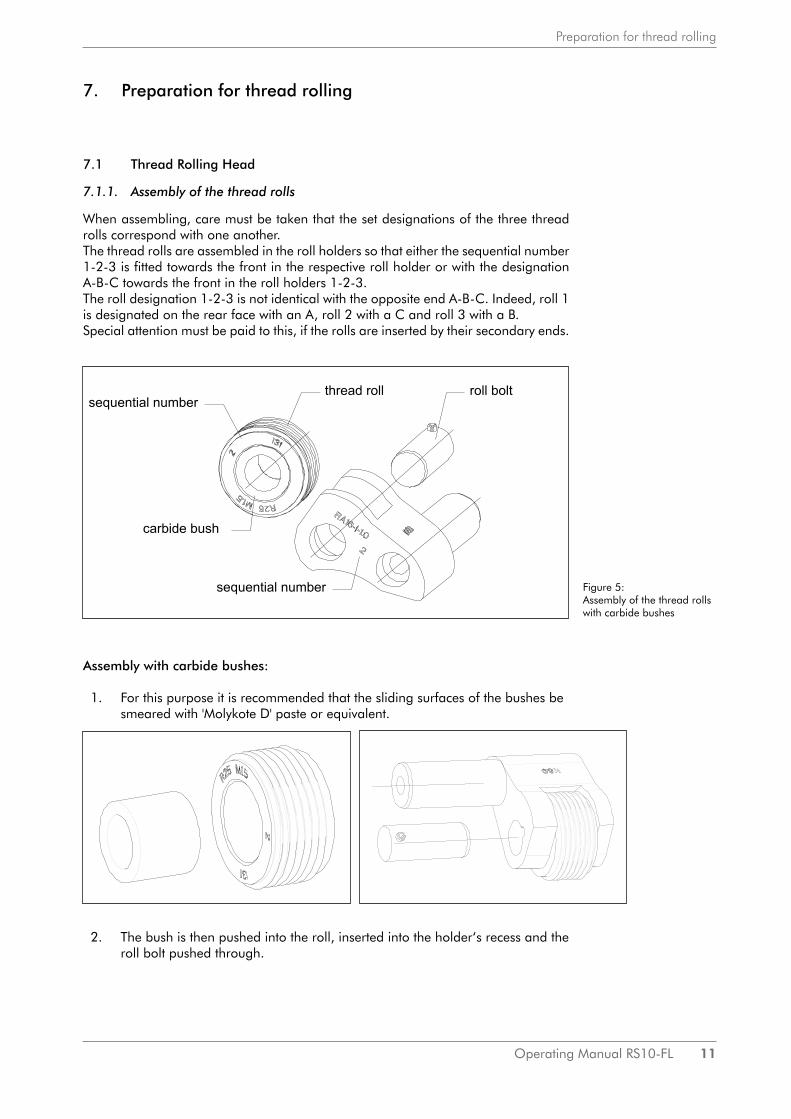
When assembling, care must be taken that the set designations of the three thread rolls correspond with one another.The thread rolls are assembled in the roll holders so that either the sequential number 1-2-3 is fitted towards the front in the respective roll holder or with the designation A-B-C towards the front in the roll holders 1-2-3.The roll designation 1-2-3 is not identical with the opposite end A-B-C. Indeed, roll 1 is designated on the rear face with an A, roll 2 with a C and roll 3 with a B.Special attention must be paid to this, if the rolls are inserted by their secondary ends.
Assembly with carbide bushes:
1. For this purpose it is recommended that the sliding surfaces of the bushes be smeared with 'Molykote D' paste or equivalent.
2. The bush is then pushed into the roll, inserted into the holder‘s recess and the roll bolt pushed through.
Figure 5: Assembly of the thread rolls with carbide bushes

12 Operating Manual RS10-FL
Preparation for thread rolling
Assembly with bearing needles:
For this purpose an assembly bolt is required. This is placed in the roll bore on a flat surface and the bearing needles are inserted individually. The roll’s bore is previously sme-ared with 'Molykote D' paste.
The right number of needles must be adhered to. You will find the specifications in the Roll Holder Table RA10 on page 32.The roll prepared in this way is then fitted into the holder as already described above. In doing so, the assembly bolt is pressed out forwards by the roll bolt.
When replacing the thread roll at the end of its service life it is recommended that new bearing needles be fitted as well.Under no circumstances may worn and new bearing needles be utilized together in one bearing. This would lead to a roll breakage due to the unequal needle diameters.In special cases double rows of needle bearings are inserted.Thereby a bronze spacing disc in placed between the two rows of needle bearings. A bush is used to facilitate assembly, this being placed on the base when the first row of needles is being inserted, and the spacer disc being laid on the bush. The roll is then turned over for the purpose of assembling the second row of needles, and likewise the needles inserted on the base.
7.1.2. Assembly of the roll holders
Assembly of the roll holders should be undertaken if at all possible in the "closed" head position. The sequence of roll holders or thread rolls must be adhered to: • in the case of right-handed threads 1-2-3 in clockwise direction,• in the case of left-handed threads 1-2-3 in counter-clockwise direction.
It is also recommended that the sliding surfaces of the roll holders be smeared thinly with 'Molykote D' paste.
Figure 6: Assembly of the thread rolls with bearing needles
Figure 7:Assembly of the roll holders

Operating Manual RS10-FL 13
Preparation for thread rolling
The roll holders are fixed inside the head by means of a screw, the pertinent retaining disc is mounted in the head and engages into the holder journal by means of serra-tion equating to an anti-twist device.When inserting the holder make sure that the teeth of the serrated surface slide into each other easily. This is the case, if the holder’s front surface is flush with the front edge of the cam ring. Not until this has been accomplished may the fixing screw be tightened. Test the holders for smooth functioning, i.e. the holders have to be pressed outwards against the cam ring by the tapered tips of the thrust bushes which are built into the head, and maintain this contact even after the cam ring has been turned.
7.1.3. Adjustment of the thread diameter
Adjustment of the head is effected most simply by means of a sample thread. The head only needs to be adjusted in closed condition until the sample workpiece is no longer turnable. Adjustment of the head is effected by means of the two set screws [3010], after having loosened the Allen screws [3050] and hence cam ring [3000]. A graduation is provided on the cam ring. Twisting in the "+" direction results in an enlargement of the thread diameter to be adjusted, and in the "-" direction in a reduction. After the loose screws have been tightened a trial thread can be rolled. Inspection of the latter using an Aggra gauge, flank micrometer, ring gauge or other measuring device will show whether readjustment is necessary. If no sample threads are available, work can also be effected using a bolt whose diameter corresponds with the core diameter of the thread.The two set screws [3010] may not be tightened excessively, otherwise distortion of the guide ring may occur, which will hinder its movabiltiy.
7.1.4. Adjustment of the thread length
The thread length is limited by the opening of the rolling head.The opening process is initiated by feed stop. Extraction of the head begins due to this and at the end of the opening stroke the head is open.On this subject see also chapter 7.2.5.
Feed stop can be achieved by:1. Limitation of the machine‘s feed stroke, e.g. by means of a positive stop or by stopping a ball screw.2. An internal stop on the thread rolling head.
In the case of both settings take note of the fact that the greatest length is achieved when the thread roll head is open. When rolling up to a collar the possible thread length is determined by the front edge of the holder or roll. (See also chapter 7.2.3).The feed stop must ensure with absolute certainty that a feed movement will no Ion-ger take place.
7.2 Workpiece / machine
7.2.1. Rollable materials
The material must be cold formable. The necessary elongation of the material is de-pendent on the volume of the deformation.In the case of materials of up to 800 N/mm² the tensile strength should be for• vee- threads: at least 7 %• Acme threads: at least 12 %
Elongation must be correspondingly greater with increasing tensile strength in order to make economic thread rolling.
Feed for thread rolling: chapter 7.2.5, page 15
Rolling threads upto a collar: chapter 7.2.3, page 15

14 Operating Manual RS10-FL
Preparation for thread rolling
7.2.2. Premachining of the workpiece
Blank premachining is dependent on the peculiarity of the material flow which takes place due to cold forming during thread rolling. The volume displaced by the crests of the thread profiles onto the rolls in the direction of the thread core must be equal to the volume inflowing into the thread crests.
Therefore the premachining diameter required for rolling corresponds roughly with the thread‘s effective diameter; the flowability of the material also being of signifi-cance.The precise premachining diameter is only determinable by trial and error. Select it so that the major diameter of the thread with the correct effective diameter is not overrolled but only lightly rolled onto.
The premachining determined in this way is the maximum dimension. The accep-table tolerance towards minus represents about 1/6 of the thread’s major diameter tolerance. If this tolerance is complied with, the major diameter will remain within the tolerance.
Changes to the premachining diameter have an effect in practice of 3 to 5 times this amount on the major diameter of the rolled thread. A change of 0.02 mm in the premachining diameter can thus cause, e.g. a change of 0.1 mm in the thread‘s major diameter.
When commencing determination of the premachining diameter it is recommended that the diameter be selected equal to the desired effective diameter. By this means a basis is obtained with which a thread is rollable. For this purpose the diameter ad-justment of the rolling head (see chapter 7.1.3) must be so selected that the correct effective diameter is achieved.
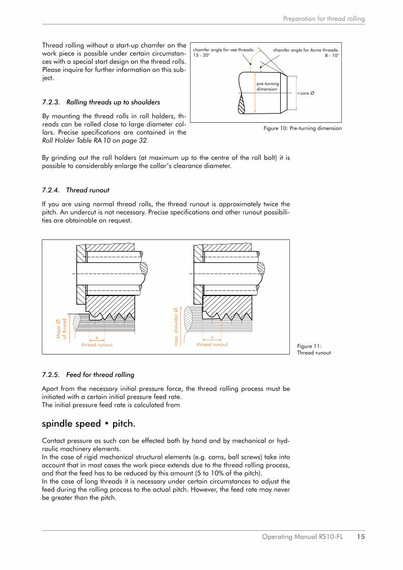
Depending on the major diameter achieved the premachining diameter is then cor-rected. Under no circumstances may the major diameter of the thread be overrolled, because this will lead to overloading and subsequent breakage of the thread rolls.At the beginning of the thread the workpiece must be provided with a chamfer for the purpose of the thread rolls‘ startup.The chamfer angle in the case of vee-threads should be 15 to 20°, in the case of Acme threads 10 to 12°. Depending on the thread pitch, the diameter at the begin-ning of the chamfer must be several tenths of a millimetre less than the core diameter. Subject to these prerequisites the initial pressure force is:
Initial pressure force (N) = Power output (KW) • 120
Adjustment of the thread diameter:
chapter 7.1.3, page 13
Figure 8: Equal in area Figure 9: Pre-machining of the workpiece
Equal in area
Operating Manual RS10-FL 15
Preparation for thread rolling
By grinding out the roll holders (at maximum up to the centre of the roll bolt) it is possible to considerably enlarge the collar’s clearance diameter.
7.2.4. Thread runout
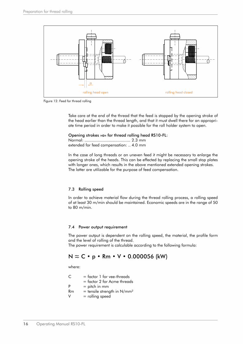
If you are using normal thread rolls, the thread runout is approximately twice the pitch. An undercut is not necessary. Precise specifications and other runout possibili-ties are obtainable on request.
7.2.5. Feed for thread rolling
Apart from the necessary initial pressure force, the thread rolling process must be initiated with a certain initial pressure feed rate.The initial pressure feed rate is calculated from
spindle speed • pitch.
Contact pressure as such can be effected both by hand and by mechanical or hyd-raulic machinery elements.In the case of rigid mechanical structural elements (e.g. cams, ball screws) take into account that in most cases the work piece extends due to the thread rolling process, and that the feed has to be reduced by this amount (5 to 10% of the pitch).In the case of long threads it is necessary under certain circumstances to adjust the feed during the rolling process to the actual pitch. However, the feed rate may never be greater than the pitch.
Thread rolling without a start-up chamfer on the work piece is possible under certain circumstan-ces with a special start design on the thread rolls.Please inquire for further information on this sub-ject.
7.2.3. Rolling threads up to shoulders
By mounting the thread rolls in roll holders, th-reads can be rolled close to large diameter col-lars. Precise specifications are contained in the Roll Holder Table RA 10 on page 32.
Figure 10: Pre-turning dimension
Figure 11: Thread runout
16 Operating Manual RS10-FL
Preparation for thread rolling
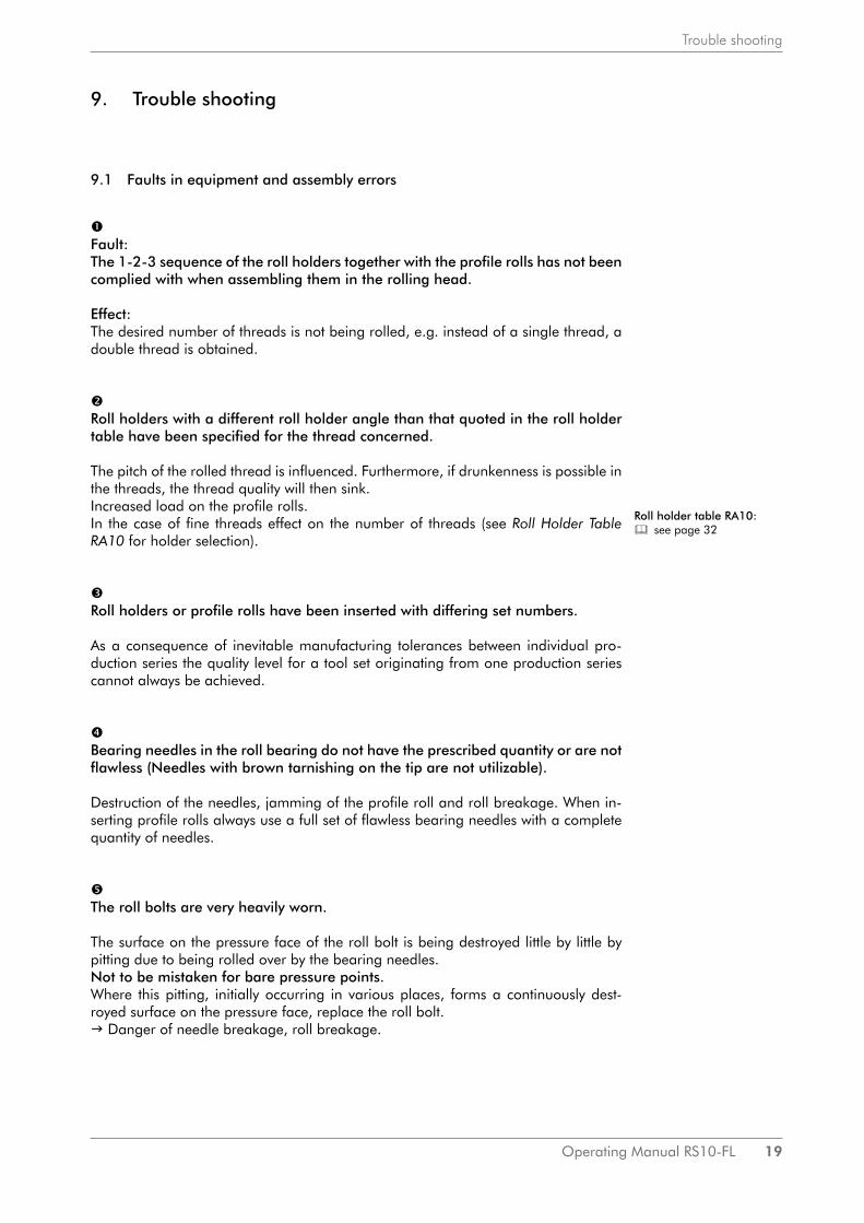
Take care at the end of the thread that the feed is stopped by the opening stroke of the head earlier than the thread length, and that it must dwell there for an appropri-ate time period in order to make it possible for the roll holder system to open.
Opening strokes »a« for thread rolling head RS10-FL:Normal: ...................................... 2.3 mmextended for feed compensation: .. 4.0 mm
In the case of long threads or an uneven feed it might be necessary to enlarge the opening stroke of the heads. This can be effected by replacing the small stop plates with longer ones, which results in the above mentioned extended opening strokes. The latter are utilizable for the purpose of feed compensation.
7.3 Rolling speed
In order to achieve material flow during the thread rolling process, a rolling speed of at least 30 m/min should be maintained. Economic speeds are in the range of 50 to 80 m/min.
7.4 Power output requirement
The power output is dependent on the rolling speed, the material, the profile form and the level of rolling of the thread.The power requirement is calculable according to the following formula:
N ~ C • p • Rm • V • 0.000056 (kW)
where:
C = factor 1 for vee-threads = factor 2 for Acme threads P = pitch in mmRm = tensile strength in N/mm²V = rolling speed
Figure 12: Feed for thread rolling
rolling head open rolling head closed
~

Operating Manual RS10-FL 17
Preparation for thread rolling
7.5 Coolant/ lubricant
Ensure an ample supply of coolant/lubricant. 7 to 10 % emulsions and thin-bodied oils, as are also used for metal cutting, are proven media.High pressure additives reduce friction between the thread roll and the workpiece.They thus contribute towards an improvement in tool life. Good filtering of the coolant/lubricant is very important, in order that no foreign materials (swarf) are rolled into the thread or settle in the roll bearing.The aftersales services of the mineral oil companies are also at your disposal for specific questions on coolants and lubricants. You should approach them where re-quired.
7.6 Tool life
Conditions for a good and economic tool life:• Exactcompliancewiththepremachiningtolerances• Compliancewiththeexactrateoffeed• Uniform,centricalstartingchamfer• Preciseconcentricitybetweenrollingheadandworkpiece‘saxis• Cleanandamplecoolant/lubricantsupply• Levelofrollingofthethread(notoverrolled!)• Seechapter 6.3 »Quality« for high material strengths and residuefree steels. Quality:
chapter 6.3, page 10

18 Operating Manual RS10-FL
Mounting on the machine
8. Mounting on the machine
Stationary thread rolling heads are normally clamped in the tool mounting by means of a shank, whereby care must be taken that they are precisely centered.WAGNER® supplies shanks in various diameters, both cylindrical and in NC-versions.The shanks are interchangeable. A device on the machine must be available for clo-sing the rolling head. Several illustrations of the principles of mounting and closing facilities on lathes are shown in Figure 13.Special closing devices are obtainable for thread rolling heads from several manu-facturers of turning machines.When making the closing cams take care of the tact that not only must a cam rise be present for the closing movement but also a fall (approx. 5°) in order that the rolling head locks.The closing roll is mounted in a fixed position on the rolling head and is readjustable in the case of the NC-shank in 90° increments by remounting the shank. If these 90°-increments are insufficient, infinite adjustment is made possible by means of an additional closing ring with a closing roll.
When used on radial turrets the thread rolling head is closable by means of a closing cam into the position opposite the work spindle while the tool inserted there is advancing.
This version is utilizable on multi-spindle automatic turning machines. This type is also possible on CNC machines with tool turrets, whereby the closing cam is firmly clamped on the tail-stock/ sleeve spindle or is fixed in another way to the machine bed.
One possibility on CNC machines. In this case the rolling head is closed by moving the rolling head’s closing roll onto the stop via the X and Y axes.
Figure 13: Mounting on the machine
Operating Manual RS10-FL 19
Trouble shooting
9. Trouble shooting
9.1 Faults in equipment and assembly errors
Fault: The 1-2-3 sequence of the roll holders together with the profile rolls has not been complied with when assembling them in the rolling head.
Effect: The desired number of threads is not being rolled, e.g. instead of a single thread, a double thread is obtained.
Roll holders with a different roll holder angle than that quoted in the roll holder table have been specified for the thread concerned.
The pitch of the rolled thread is influenced. Furthermore, if drunkenness is possible in the threads, the thread quality will then sink. Increased load on the profile rolls. In the case of fine threads effect on the number of threads (see Roll Holder Table RA10 for holder selection).
Roll holders or profile rolls have been inserted with differing set numbers.
As a consequence of inevitable manufacturing tolerances between individual pro-duction series the quality level for a tool set originating from one production series cannot always be achieved.
Bearing needles in the roll bearing do not have the prescribed quantity or are not flawless (Needles with brown tarnishing on the tip are not utilizable).
Destruction of the needles, jamming of the profile roll and roll breakage. When in-serting profile rolls always use a full set of flawless bearing needles with a complete quantity of needles.
The roll bolts are very heavily worn.
The surface on the pressure face of the roll bolt is being destroyed little by little by pitting due to being rolled over by the bearing needles. Not to be mistaken for bare pressure points. Where this pitting, initially occurring in various places, forms a continuously dest-royed surface on the pressure face, replace the roll bolt. Danger of needle breakage, roll breakage.
Roll holder table RA10: see page 32

20 Operating Manual RS10-FL
Trouble shooting
The rolling head does not open sufficiently:
Markings on the major diameter of the thread by the profile rolls when pulled out. Cause: • rolling head is heavily contaminated: please clean!
or:• the springs for the purpose of opening the rolling head are fatigued.
The coolant is contaminated with swarf or abrasives:
• The thread flanks are becoming rough and flaky. In the case of large swarf chips, danger of breakage for the profile rolls due to being rolled over, or to jamming.
• Moreover, impairment of the head function due to contamination. Remedy: filter in the coolant line and screening of the rolling head station against swarf.
Concentricity precision between the rolling head and the workpiece is insuffici-ent:
The thread has been rolled onesided or the thread bolt is bent (in the case of long bars) or the thread is tapered (in the case of short threads). In the case of marked deviation: danger of breakage for the profile rolls.
Blanks with marked diameter deviations (rolled material) or bent blanks:
Threads which are not flawlessly rolled, bent thread bars. Danger of breakage for profile rolls due to extreme overrolling in some places. Thread profile rolling tools are not straightening rolls.
The instructions on the adjustment of the thread diameter and for the purpose of determining the premachining diameter of the workpiece have not been adhered to:
A nonrolled thread or roll breakage due to an overrolled thread.
⓫The starting chamfer at the beginning of the bolt has not been correctly selected:
The beginning of the thread is unclean, the first few threads have sheared off. In the case of an excessively large starting chamfer the starting pressure force is too great. Due to this increased wear on profile rolls. Starting chamfer angle: • for vee-threads: 15°• for Acme threads: 8...10° commencing 0.4...0.8 mm less than the core diameter. If the starting chamfer is not positioned centrically, the thread will also not be rolled on centrically; in the case of short threads they may turn out to be tapered.

Operating Manual RS10-FL 21
Trouble shooting
⓬The feed applied for the purpose of rolling does not correspond with the thread pitch per revolution when rolling:
Thread beginning unclean. At excessively slow starting pressure the thread profiles of the rolls do not engage into the prescribed thread pitch, but only press into the star-ting chamfer, so that the material is hardened to an unacceptable degree - danger of profiles breaking on the rolls. If starting pressure is too fast an excessively strong force is exerted on the roll profiles. Likewise danger of breaking. Rolling has been effected in compliance with the pitch, if only one thread is visible at the start of the thread and not several profiles adjacent to one another which do not unite into one thread until after the second thread.
⓭Feed during thread rolling is not in compliance with the pitch:
A forward feed applied during rolling which does not comply precisely with the th-read pitch arising in the rolling tools during the rolling process, influences the pitch (pitch errors) and exerts an undesired force on the rolling tools. Therefore switch off the forward feed after rolling the first two or three threads in order that the workpiece is pulled through the rolling tools with as little resistance as possible. In special cases an extraction extension can provide a remedy (see chapter 7.2.5 und 10.4).
⓮ The limit stop for opening the head when it rolls up against a shoulder has not been correctly employed or adjusted:
The profile rolls or the roll holders run up against the shoulder on the workpiece. A roll breakage occurs.
⓯The force is too small to clamp the workpiece:
During rolling the workpiece is pressed back into the clamping device, or the work-piece slips during rolling, or upon reaching the thread length the workpiece is pulled out of the clamping device when the forward feed is stopped, and the rolling head does not open. The desired thread length is not achieved. Furthermore, increased danger of roll breakage.
⓰Rolling speed too slow:
At rolling speeds of less than 30 m/min productivity drops markedly.
⓱Repeated overrolling of a thread or re-rolling of a thread which has already been cut:
Danger of breakage exists for the profile rolls. Particularly, if a thread, which has already been rolled, is rolled over again, because compaction of the material took place when the thread was rolled the first time.
Feed for thread rolling: chapter 7.2.5, page 15
22 Operating Manual RS10-FL
Trouble shooting
9.2 Defects in the rolled thread
Fault: The thread has not been rolled uniformly about the major diameter and has been partially overrolled:
Cause and remedy: • Check whether the premachining diameter has been uniformly complied
with and the concentricity of the rolling head with the workpiece is sufficiently precise.
• However, the possibility also exists that the material is not uniform or homo-geneous, e.g. rolled or forged material has decarbonized outer layers.
The effective diameter is not uniform:The premachining diameter has not been uniformly maintained
The thread is incomplete and only partially rolled:• Check whether the rolling head is correctly engaged when it closes (contami-
nation) or • in the case of rotating rolling heads whether the closing device is pressing the
rolling head sufficiently far into the locking plates' dwell position. • Furthermore, verify whether the set screws [3010] and the cheese head
screws [3050] in the cam ring are perfectly tight.
The thread has a double instead of a single start:Check the sequence of the profile rolls.If the sequence is correct, excessive pressure was applied when the rolling was star-ted. Be careful with fine threads!
Thread becomes slightly tapered in the case of short threads:• The threaded bolt has a bore, or centre hole. If the walls are too thin the
thread will be compressed more intensively. • Remedy: make the bore after the thread rolling operation.
• The rolling head has difficulty in opening. • Clean the rolling head and render the parts freely movable. • The starting chamfer is unfavourable, causing too much material to be dis-
placed in axial direction at the start of the thread.
Profile rolls are breaking off:The thread has been rolled over too heavily about the major diameter, i. e. it has been rolled with excessive pressure, or upon initial rolling the rolls were forced in too hard or the workpiece was not driven into the rolls centrically enough. Due to contamination of the coolant by swarf the rolls are jammed, or swarf between the workpiece and the profile rolls produces excessive pressure.

Operating Manual RS10-FL 23
Trouble shooting
The threaded bolt or threaded rod becomes bent:• The rolling head and the workpiece are not sufficiently concentric. • The starting chamfer has not been executed sufficiently centrically. • In the case of pipes: inside and outside diameters are not concentric. The
material has internal stress and a nonuniform texture. This can be partially remedied by annealing.
• In the case of rolled material: due to a nonuniform initial diameter partial overrolling of the major diameter takes place. Excessive distance between the workpiece clamp and the point of application of the profile rolls. Excessively low rolling speed can also be the cause of bent threaded rods.
The thread pitch is unsatisfactory:The thread pitch is not uniform. • Check feed carriage for easy running when subjected to a load (rolling mo-
ment).• Check the workpiece whether the thread has been uniformly rolled and not
only partially.• Nonuniform, nonhomogeneous material may be the cause.
Thread pitch tends uniformly to plus or minus:• If the thread has been rolled flawlessly, the cause may be the material. This
can be slightly corrected by replacing the roll holder with the next smaller or next larger pitch angle. Larger pitch corrections are only possible by using special rolls with a specially corrected pitch.
• In the case of some materials the pitch can also be slightly influenced by clo-sing or opening, as long as this is still possible within the diametral toleran-ces of the thread.
Thread flanks are flaking off or have a rough or patchy surface; threads are de-stroyed when rolled:The material is not suitable for rolling, because it is too brittle, or has experienced unacceptable hardening due to aforegoing cold forming, e.g. colddrawn materials. High proportions of sulphur or lead which favour short machining in the case of free cutting steel, also have an unfavourable effect on the surface finish with rolled threads.Furthermore, swarf and abrasives in the coolant exert a damaging influence on the surface finish, and under certain circumstances residues of lubricants on the surface of colddrawn materials. A surface which has been too coarsely premachined may also have consequential effects on the rolled thread surface.

24 Operating Manual RS10-FL
Care and Maintenance
10. Care and Maintenance
10.1 Maintenance intervals
A certain degree of care is also required in order to maintain the functionality and functional reliability of the thread rolling head. This means that the head ought to be cleaned and checked for possible wear at regular intervals, these being dependent on operating conditions.We recommend the first service after approximately 200,000 threads.
10.2 Disassembly of the rolling head
It is expedient for this purpose to partially dismantle the head. To be precise:
1. having removed the roll holders, and after unscrewing one of the threaded pins [3010] and both of the allen head screws [3050] the cam ring [3000] should be pulled off the guide ring [300]. Subsequent to this, the three sealing discs [760] are pulled or pressed off by means of a thread. The slotted round nuts [740] which now become visible beneath these are now also unscrewed. The body unit [100] complete with guide ring [300] can now be removed from the flange [670].
2. The contact surfaces which are now exposed can in this way be cleaned from adhering abrasive metal particles and other contaminants. This opportuni-ty should be taken to inspect the locking plates [690] and small locking pla-tes [370] for wear on their locking edges, and replace them where required. Warning: plates [370] and screws [380] are glued with Loctite 638! Excessive wear (rounding) of the locking edges can cause premature opening of the head or indeed completely prevent closure.
3. Inspect thrust bushings [160] for function. If not easy running „pull out and clean“. 4. If functional defects occur within the twisting mechanism between the body unit
[100] and guide ring [300], the twisting mechanism must be demounted.The procedure for demounting is as follows: Check whether a mark is present on the flange side of the body unit [100] and guide ring [300]. This mark was not provided ex factory on older models. However, prior to further demounting work it should be applied without fail in a similar form in order to facilitate reassembly.
5. Remove protective plate [550] by unscrewing the closing roll [510] and removing one countersunk screw [340]. Remove remaining screws [340]. Unscrew screws [130] + [140] through the guide ring‘s bores. Pull body unit [100] out of the guide ring [300]. Remove clamping segments [110], closing segments [320] and [330] and pressure springs [360] from the guide ring‘s groove.
6. Clean parts and check for damage.

Operating Manual RS10-FL 25
Care and Maintenance
10.3 Reassembly of the rolling head
Procedure for reassembly is as follows:1. Oil parts slightly.
2. Secure closing segments [320] by means of ore screw [340] each in the groove of the guide ring [300]. In so doing take heed of differing threaded borings and line them up with the appropriate through bores. Insert clamping segments [110] likewise into the groove complying with an asymmetrical fit position for the an-nular groove in the body unit [100] and with the correct position relative to the closing segments, i. e. under the mounting bores of the guide ring [300].
3. Insert the pressure springs [360] between the segments. Push body unit [100] into the guide ring [300]
4. Remove screws [340] again. Secure the clamping segments by means of the as-sembly bores using screws [130] and [140]. In so doing take heed that the marks on the side of the flange are aligned one over the other.
5. Secure the closing segments by means of one screw [340] each in the bore asym-metrical to the adjacent groove!
6. Check the function of the twisting mechanisms, any absence of easy running indicates tilted segments. This can be eliminated by means of a light blow on the body unit when the guide ring is in place.
7. Place retaining discs [750] in the appropriate recesses in flange [670]. Place body unit with guide ring on the flange, taking heed of the correct position of the carrier bolt [680], of the locking and stop plates [370] and [690]. Insert pressure springs [730] on top of carrier bolt [680]. Tighten slotted round nuts [740].
8. Check functioning of head extraction and locking. Insert sealing discs [760]. Mount cam ring [100]. Clamp cam ring tight by means of clamping screws [1050].
9. Assemble roll holders. Check overall function.

26 Operating Manual RS10-FL
Dimensions
11. Dimensions
11.1 Rolling head RS10
11.2 Closing ring
Operating Manual RS10-FL 27
Dimensions
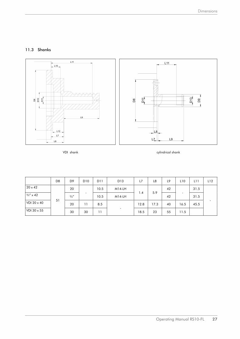
11.3 Shanks
D8 D9 D10 D11 D13 L7 L8 L9 L10 L11 L12
20 x 42
51
20-
10.5 M14-LH1.4 5.9
42-
31.5
-
¾” x 42 ¾” 10.5 M14-LH 42 31.5
VDI 20 x 40 20 11 8.5-
12.8 17.3 40 16.5 45.5
VDI 30 x 55 30 30 11 18.5 23 55 11.5
VDI shank cylindrical shank

28 Operating Manual RS10-FL
Spare Parts
12. Spare Parts
12.1 Thread rolling head RS10-FL | Article No. 74878500
Item No. Quantity Name Article No.
10 1 Head body 72038300
11 2 Clamping segment 71063700
13 2 Cheese head screw M5x10 02018102
14 2 Cheese head screw M5x12 02018103
15 3 Pressure spring 03310703
16 3 Thrust bushing 71064100
30 1 Guide ring 74878700
32 1 Closing segment 71063800
33 1 Closing segment 71063900
34 3 Countersunk screw M5x10 02018102
36 2 Pressure spring 03310101
37 2 Small stop plate 71064000
38 2 Countersunk screw M4x6,5 02018010
50 1 Closing bolt 70584900
51 1 Closing roll 70585100
52 1 Cup spring 02320004
54 1 Cheese head screw M6x20 02016105
55 1 Protective plate 70584700
67 1 Flange 73036100
68 3 Carrier bolt 70584600
69 2 Locking plate 70585500
70 2 Countersunk screw M4x6,5 02018010
73 3 Pressure spring 03310042
74 3 Slotted round nut M4 02070010
75 3 Retaining disc 71064300
76 3 Sealing washer 71064400
300 1 Cam ring 74878600
301 2 Ball pressure screw M6x16 02045157
303 3 Insertion piece 71064200
305 3 Countersunk screw M4x18 02018018
Accessories
306 1 Threaded bolt 70585000
401 1 Ball knob 02270007
501 3 Retaining screw M4x43 70584800
502 1 Screw driver 25 02677002
503 1 Screw driver 3 02677003
526 1 Spanner wrench size SW 68 02670027

Operating Manual RS10-FL 29
Spare Parts
12.2 Exploded drawing

30 Operating Manual RS10-FL
Spare Parts

Operating Manual RS10-FL 31
Spare Parts
12.3 Shanks and relative internal stops
Shankdesignation
Ø D6 Article no.shank
Article no.internal stop
20 x 42 20 73075700 73146000
¾” x 42 ¾” 73075800 73146000
VDI 20 x 40 20 73077200 -
VDI 30 x 55 30 73077400 -
Internal stop 73146000
Item No. Quantity Name Article No.
701 1 Threaded bush 70585700
702 1 Stop spindle 70565000
703 1 Hex. nut M 8 LH 02061506
704 1 Steel ball Ø 4 02460112
705 1 Stop Ø 2.8 70567600
707 1 Stop Ø 7 70567700
708 2 Snap ring 02087001
712 2 Back-up ring 73145700
716 1 Back-up ring 73145800

32 Operating Manual RS10-FL
Roll holder table RA10W
AG
NER
-WER
KZEU
GSYSTEM
EM
ÜLLER
Gm
bHG
utenbergstrasse 4/1D
-72124 PliezhausenTel. 07127/973 300Telefax: 07127/973 390em
ail: info@w
agner-werkzeug.de
Roll holder
Rolls
Rolling range
Thread typesD
esignationD
esignationC
ore dia. in mm
Metric
Metric
Whitw
orth-B
SF
Whitw
orth-A
merican threads
Prod.-N
o.from
... tothread
fine threadthread
threadpipe thread
Max. shoulder dia.
Max. out-dia.
DIN
13D
IN 13
DIN
11D
IN 259, 2999
UN
CU
NF
UN
EF
UN
UN
SN
PT
RA
10-0-4,0 KD+0,85
R20/9,8
1,5 … 4,0
M2,2
Nr.2-56
Nr.2-64
73942000KD
+1,05R
20/10,51,7 …
4,0M
2,5N
r.3-48N
r.3-56KD
+1,2R
201,8 ... 4,0
M3 - M
3,5M
2,5x0,35N
r.4-40N
r.4-48R
A10-1-5,0
R21/14
2,2 ... 3,4M
31/8
Nr. 5-40
Nr. 5-44
757400008,8
M3,5
Nr. 6-32
Nr. 6-40
KD
+ 3,4R
212,8 ... 4,0
M4
1/323/16x1/32
Nr. 8-32
Nr. 8-36
Nr. 10-28
5,8M
4,57/32x1/28
Nr. 10-24
Nr. 10-32
KD
+ 6,4N
r. 12-24R
A10-1-3,0
R21/14
2,2 ... 3,4M
3M
3x0,3575740200
8,8M
3,5M
3,5x0,35K
D + 3,4
R21
2,8 ... 4,0M
4-5x0,355,8
M4-5x0,5
KD
+ 6,4R
A10-2-4,0
M5 - M
10M
5,5-6,5x0,751/4
1/4x1/261/4-20
Nr. 12-28
Nr. 12-32
5/16-20N
r. 10-36...4075740400
M7,5-8,5x1
5/165/16x1/22
5/16-181/4-28
1/4-32N
r. 12-36...40K
D + 7,4
M10x1,25
3/83/8x1/20
3/8-16...205/16-24
1/4-24...365/16-273/8-18
RA
10-2-2,5R
233,8 ... 8,6
M5,5-6x0,5
R1/8
3/8-245/16-32
5/16-28N
r.10-48...561/16-27
7574060010,3
M7-9,5x0,75
3/8-323/8-28
Nr.12-48...56
1/8-27K
D + 7,4
M9-10x1
1/4-40...485/16-36...40
0,390-273/8-27...36
RA
10-2-1,5M
5,5-9x0,351/4-56
75742400M
6,5-9x0,55/16-48
KD
+ 7,43/8-40
KD
= Core diam
eter
Roll O
D/bor x w
idthP
cs. needlesP
roduct-No.
Roll bolt
Product- N
o. C
arbide bushesP
roduct-No.
dia. x lengthdia. x length
OD
/bore x width
R20/9,8=9,8/6x8
R20/10,5=10,5/6x8
--
6x18,272000500
--
R20=11/6x8
R21/14=14/9x8
45-1,5x7,803462053
6x18,272000500
9/6x7,903463106
R21=17/9x8
R23=20/11x10
57-1,5x9,803462054
8x18,272000400
11/8x9,903463101
Roll holder table R
A 10 for thread rolling heads Typ RS 10 und R
AR 10-2
Roll holder table R
A 10 for thread rolling heads Typ RS 10-FL und R
AR 10-FL
21.04.2016
13. Roll holder table RA10

ImprintThis operating manual is a publication made by WAGNER® Werkzeugsysteme Müller GmbH. Information in this catalog is current as of publication date and subject to change.All rights reserved.
Date: 08 | 2016
WAGNER® Werkzeugsysteme Müller GmbHGutenbergstraße 4/1D-72124 Pliezhausen
phone: +49(0) 71 27/ 97 33-00fax: +49(0) 71 27/ 97 33-90
email: [email protected]: www.wagner-werkzeug.de