operating manual - sunny home manager 2 › pdf › sunny_home_manager_2.0_manual.pdf · this...
TRANSCRIPT

Reset
SUNNY HOME MANAGER 2.0
Operating ManualSUNNY HOME MANAGER 2.0
HM-20-BE-en-10 | Version 1.0ENGLISH

Legal ProvisionsThe information contained in these documents is property of SMA Solar Technology AG. Any publication, whether inwhole or in part, requires prior written approval by SMA Solar Technology AG. Internal reproduction used solely forthe purpose of product evaluation or other proper use is allowed and does not require prior approval.
SMA WarrantyYou can download the current warranty conditions from the Internet at www.SMA-Solar.com.
Software licensesThe software licenses for the installed software modules are contained in the Sunny Home Manager software. Uponconnection of the Sunny Home Manager with a web browser, you will find the licenses at the following address:http://IP_address/legal_notices.txt. The IP address (e.g. 192.168.1.120) will be assigned by your router for theSunny Home Manager. You will find further information on determining the IP address in your router documentation.
TrademarksAll trademarks are recognized, even if not explicitly identified as such. Missing designations do not mean that aproduct or brand is not a registered trademark.Modbus® is a registered trademark of Schneider Electric and is licensed by the Modbus Organization, Inc.QR Code is a registered trademark of DENSO WAVE INCORPORATED.Phillips® and Pozidriv® are registered trademarks of Phillips Screw Company.Torx® is a registered trademark of Acument Global Technologies, Inc.
SMA Solar Technology AGSonnenallee 134266 NiestetalGermanyTel. +49 561 9522-0Fax +49 561 9522-100www.SMA.deEmail: [email protected]
Status: 5/4/2017Copyright © 2017 SMA Solar Technology AG. All rights reserved.
Legal Provisions SMA Solar Technology AG
Operating ManualHM-20-BE-en-102
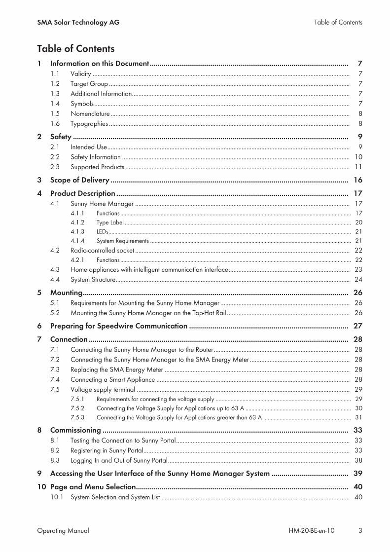
Table of Contents1 Information on this Document..................................................................................................... 7
1.1 Validity ............................................................................................................................................................. 71.2 Target Group ................................................................................................................................................... 71.3 Additional Information..................................................................................................................................... 71.4 Symbols............................................................................................................................................................ 71.5 Nomenclature .................................................................................................................................................. 81.6 Typographies ................................................................................................................................................... 8
2 Safety ............................................................................................................................................ 92.1 Intended Use.................................................................................................................................................... 92.2 Safety Information ........................................................................................................................................... 102.3 Supported Products ......................................................................................................................................... 11
3 Scope of Delivery ......................................................................................................................... 16
4 Product Description ...................................................................................................................... 174.1 Sunny Home Manager ................................................................................................................................... 17
4.1.1 Functions ........................................................................................................................................................... 174.1.2 Type Label ........................................................................................................................................................ 204.1.3 LEDs................................................................................................................................................................... 214.1.4 System Requirements ....................................................................................................................................... 21
4.2 Radio-controlled socket ................................................................................................................................... 224.2.1 Functions ........................................................................................................................................................... 22
4.3 Home appliances with intelligent communication interface.......................................................................... 234.4 System Structure............................................................................................................................................... 24
5 Mounting....................................................................................................................................... 265.1 Requirements for Mounting the Sunny Home Manager ............................................................................... 265.2 Mounting the Sunny Home Manager on the Top-Hat Rail ........................................................................... 26
6 Preparing for Speedwire Communication ................................................................................. 27
7 Connection .................................................................................................................................... 287.1 Connecting the Sunny Home Manager to the Router ................................................................................... 287.2 Connecting the Sunny Home Manager to the SMA Energy Meter ............................................................. 287.3 Replacing the SMA Energy Meter ................................................................................................................. 287.4 Connecting a Smart Appliance ...................................................................................................................... 287.5 Voltage supply terminal .................................................................................................................................. 29
7.5.1 Requirements for connecting the voltage supply ........................................................................................... 297.5.2 Connecting the Voltage Supply for Applications up to 63 A ....................................................................... 307.5.3 Connecting the Voltage Supply for Applications greater than 63 A ........................................................... 31
8 Commissioning ............................................................................................................................. 338.1 Testing the Connection to Sunny Portal.......................................................................................................... 338.2 Registering in Sunny Portal.............................................................................................................................. 338.3 Logging In and Out of Sunny Portal............................................................................................................... 38
9 Accessing the User Interface of the Sunny Home Manager System ....................................... 39
10 Page and Menu Selection............................................................................................................ 4010.1 System Selection and System List ................................................................................................................... 40
Table of ContentsSMA Solar Technology AG
Operating Manual 3HM-20-BE-en-10

10.2 My Sunny Home Manager System................................................................................................................ 4010.2.1 PV System Profile.............................................................................................................................................. 4010.2.2 Current Status And Forecast............................................................................................................................ 4110.2.3 Energy Balance ................................................................................................................................................ 4510.2.4 Load Balance and Control .............................................................................................................................. 5110.2.5 Energy and Power............................................................................................................................................ 5210.2.6 Annual Comparison ......................................................................................................................................... 5310.2.7 System Monitoring ........................................................................................................................................... 5310.2.8 PV System Logbook.......................................................................................................................................... 55
10.3 Analysis ............................................................................................................................................................ 5610.4 Performance Ratio ........................................................................................................................................... 5810.5 System Report .................................................................................................................................................. 5910.6 Devices ............................................................................................................................................................. 5910.7 Configuration ................................................................................................................................................... 59
10.7.1 System Properties ............................................................................................................................................. 5910.7.2 System Presentation ......................................................................................................................................... 6010.7.3 Device Overview.............................................................................................................................................. 6010.7.4 Load Overview and Planning.......................................................................................................................... 6110.7.5 Report Configuration........................................................................................................................................ 6210.7.6 User Management ........................................................................................................................................... 62
11 Page Settings ................................................................................................................................ 6311.1 Diagram Settings ............................................................................................................................................. 63
11.1.1 Setting the Display Period................................................................................................................................ 6311.1.2 Saving Diagram Data ...................................................................................................................................... 6311.1.3 Printing Diagram Data ..................................................................................................................................... 6311.1.4 Enlarging the View ........................................................................................................................................... 6311.1.5 Showing and Hiding the Legend .................................................................................................................... 63
11.2 Sorting the System List ..................................................................................................................................... 6411.3 Showing, Hiding and Sorting Loads............................................................................................................... 6411.4 Publishing Pages .............................................................................................................................................. 64
11.4.1 Releasing Pages for Viewing in Sunny Portal ................................................................................................. 6411.4.2 Presenting Sunny Portal Pages on the Internet ............................................................................................... 64
12 Device Settings ............................................................................................................................. 6612.1 Filtering the Device Overview......................................................................................................................... 6612.2 Calling Up the Properties of a Device............................................................................................................ 6612.3 Calling Up the Device Parameters ................................................................................................................. 6612.4 Updating Parameters....................................................................................................................................... 6712.5 Reading Off the Software Package Version .................................................................................................. 6712.6 Configuring the Energy Meter ........................................................................................................................ 6712.7 Setting the Data Request Interval.................................................................................................................... 6812.8 Activating/Deactivating Automatic Software Updates ................................................................................. 6912.9 Entering Line Conductors................................................................................................................................. 7012.10 Entering the PV Array Power........................................................................................................................... 7012.11 Changing the Device Name ........................................................................................................................... 7112.12 Changing a Device Description...................................................................................................................... 71
13 Load Control ................................................................................................................................. 7213.1 Information on Load Control........................................................................................................................... 72
Table of Contents SMA Solar Technology AG
Operating ManualHM-20-BE-en-104

13.2 Configuring Radio-Controlled Sockets ........................................................................................................... 7213.2.1 Safety when Configuring Radio-controlled Sockets....................................................................................... 7213.2.2 Requirements when Configuring Radio-Controlled Sockets .......................................................................... 7313.2.3 Activating/Deactivating Data Collection........................................................................................................ 7313.2.4 Selecting the Load............................................................................................................................................ 7313.2.5 Entering the Device Name............................................................................................................................... 7413.2.6 Configuring the Operating Mode................................................................................................................... 74
13.3 Configuring Loads ........................................................................................................................................... 7513.3.1 Calling Up the Properties of a Load ............................................................................................................... 7513.3.2 Changing the Color Selection for Loads ........................................................................................................ 7513.3.3 Selecting the Load Icon ................................................................................................................................... 7513.3.4 Selecting the Load Type................................................................................................................................... 7613.3.5 Selecting Program Controllability.................................................................................................................... 7613.3.6 Entering the Load Name.................................................................................................................................. 7713.3.7 Entering the Power Consumption .................................................................................................................... 7713.3.8 Entering the Maximum Program Operating Time .......................................................................................... 7713.3.9 Entering the Minimum Switch-On Time ........................................................................................................... 7813.3.10 Entering the Minimum Switch-Off Time ........................................................................................................... 7813.3.11 Assigning Radio-Controlled Sockets ............................................................................................................... 7813.3.12 Setting Measuring and Switching of the Radio-Controlled Socket ............................................................... 7913.3.13 Setting Automatic Switch-Off........................................................................................................................... 7913.3.14 Setting the Priority of the Load......................................................................................................................... 8013.3.15 Configuring the Time Period ............................................................................................................................ 80
13.4 Directly Controlling Loads............................................................................................................................... 82
14 System Management ................................................................................................................... 8414.1 Adding or Replacing Devices ......................................................................................................................... 8414.2 Activating/Deactivating Devices .................................................................................................................... 8514.3 Replacing the Sunny Home Manager............................................................................................................ 8514.4 Reassigning the Sunny Home Manager to the Sunny Portal System after the Reset .................................. 8614.5 Deleting a Device from Sunny Portal.............................................................................................................. 8814.6 Deleting the Sunny Home Manager System.................................................................................................. 88
15 System Monitoring ....................................................................................................................... 8915.1 PV System Monitoring Options....................................................................................................................... 8915.2 PV System Logbook ......................................................................................................................................... 89
15.2.1 Calling Up and Filtering Messages ................................................................................................................ 8915.2.2 Confirming Messages ...................................................................................................................................... 90
15.3 Reports ............................................................................................................................................................. 9015.3.1 Report Overview .............................................................................................................................................. 9015.3.2 Configuring Reports ......................................................................................................................................... 9115.3.3 Creating a Report for a Specific Date ............................................................................................................ 93
15.4 Setting Communication Monitoring................................................................................................................ 9315.5 Setting the Inverter Comparison ..................................................................................................................... 94
16 System Settings............................................................................................................................. 9616.1 Entering String Properties ................................................................................................................................ 9616.2 Changing System Data ................................................................................................................................... 9716.3 Changing the System Name........................................................................................................................... 9716.4 Setting the Nominal PV System Power ........................................................................................................... 98
16.4.1 Manually Entering the Nominal PV System Power ........................................................................................ 98
Table of ContentsSMA Solar Technology AG
Operating Manual 5HM-20-BE-en-10
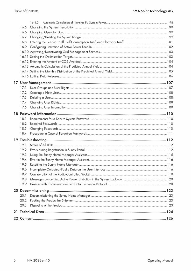
16.4.2 Automatic Calculation of Nominal PV System Power.................................................................................... 9816.5 Changing the System Description................................................................................................................... 9916.6 Changing Operator Data ............................................................................................................................... 9916.7 Changing/Deleting the System Image........................................................................................................... 9916.8 Entering the Feed-in Tariff, Self-Consumption Tariff and Electricity Tariff .....................................................10116.9 Configuring Limitation of Active Power Feed-In .............................................................................................10216.10 Activating/Deactivating Grid Management Services ...................................................................................10316.11 Setting the Optimization Target ......................................................................................................................10316.12 Entering the Amount of CO2 Avoided...........................................................................................................10416.13 Automatic Calculation of the Predicted Annual Yield ...................................................................................10416.14 Setting the Monthly Distribution of the Predicted Annual Yield ....................................................................10516.15 Editing Data Releases......................................................................................................................................106
17 User Management .......................................................................................................................10717.1 User Groups and User Rights .........................................................................................................................10717.2 Creating a New User ......................................................................................................................................10817.3 Deleting a User ................................................................................................................................................10817.4 Changing User Rights......................................................................................................................................10917.5 Changing User Information.............................................................................................................................109
18 Password Information .................................................................................................................11018.1 Requirements for a Secure System Password ................................................................................................11018.2 Required Passwords ........................................................................................................................................11018.3 Changing Passwords.......................................................................................................................................11018.4 Procedure in Case of Forgotten Passwords ...................................................................................................111
19 Troubleshooting............................................................................................................................11219.1 States of All LEDs .............................................................................................................................................11219.2 Errors during Registration in Sunny Portal ......................................................................................................11219.3 Using the Sunny Home Manager Assistant ...................................................................................................11519.4 Error in the Sunny Home Manager Assistant.................................................................................................11619.5 Resetting the Sunny Home Manager .............................................................................................................11619.6 Incomplete/Outdated/Faulty Data on the User Interface............................................................................11619.7 Configuration of the Radio-Controlled Socket ...............................................................................................11919.8 Messages concerning Active Power Limitation in the System Logbook .......................................................12019.9 Devices with Communication via Data Exchange Protocol ..........................................................................120
20 Decommissioning .........................................................................................................................12320.1 Decommissioning the Sunny Home Manager ...............................................................................................12320.2 Packing the Product for Shipment ...................................................................................................................12320.3 Disposing of the Product .................................................................................................................................123
21 Technical Data ..............................................................................................................................124
22 Contact ..........................................................................................................................................126
Table of Contents SMA Solar Technology AG
Operating ManualHM-20-BE-en-106

1 Information on this Document
1.1 ValidityThis document is valid for the device type "HM-20" (Sunny Home Manager 2.0) from firmware version 2.0.13.R.
1.2 Target GroupThe tasks described in this document must only be performed by qualified persons. Qualified persons must have thefollowing skills:
• Training in how to deal with the dangers and risks associated with installing and using electrical devices andinstallations
• Training in the installation and commissioning of electrical devices and installations• Knowledge of the applicable standards and directives• Knowledge of and compliance with this document and all safety information
1.3 Additional InformationLinks to additional information can be found at www.SMA-Solar.com:
Document title and content Document type
"SMA Smart Home" Planning Guidelines
"SMA FLEXIBLE STORAGE SYSTEM"Increased Self-Consumption with Sunny Island and Sunny Home Manager
Quick Reference Guide
"SMA SMART HOME - Load Control via MUST Time Period - Example: WashingMachine"
Technical Information
"SMA SMART HOME - Load Control via CAN Time Period - Example: PoolPump"
Technical Information
"SMA SMART HOME Load Control Using Relays or Contactors - Example: Heat-ing Rod"
Technical Information
"SMA SMART HOME - Home appliance energy management using EEBus" Technical Information
"SMA SMART HOME - Battery Charging Management with Time-of-Use EnergyTariffs"
Technical Information
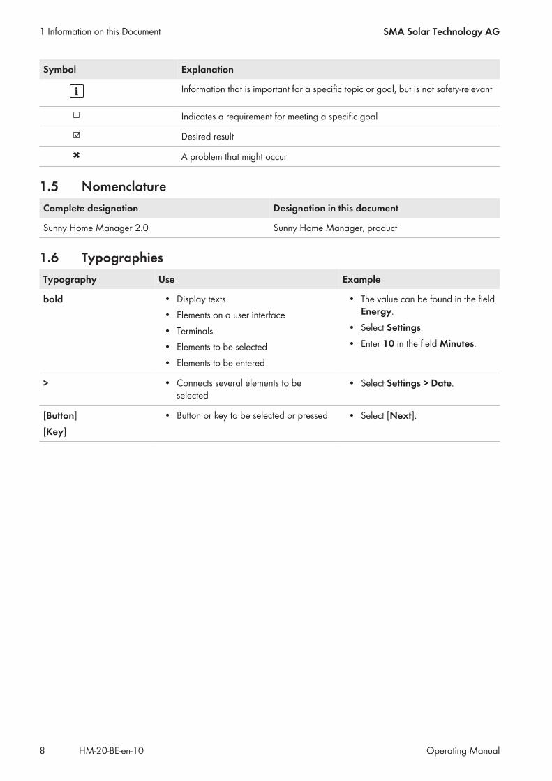
1.4 SymbolsSymbol Explanation
Indicates a hazardous situation which, if not avoided, will result in death or seri-ous injury
Indicates a hazardous situation which, if not avoided, can result in death or seri-ous injury
Indicates a hazardous situation which, if not avoided, can result in minor or mod-erate injury
Indicates a situation which, if not avoided, can result in property damage
1 Information on this DocumentSMA Solar Technology AG
Operating Manual 7HM-20-BE-en-10
Symbol Explanation
Information that is important for a specific topic or goal, but is not safety-relevant
Indicates a requirement for meeting a specific goal
Desired result
A problem that might occur
1.5 NomenclatureComplete designation Designation in this document
Sunny Home Manager 2.0 Sunny Home Manager, product
1.6 TypographiesTypography Use Example
bold • Display texts• Elements on a user interface• Terminals• Elements to be selected• Elements to be entered
• The value can be found in the fieldEnergy.
• Select Settings.• Enter 10 in the field Minutes.
> • Connects several elements to beselected
• Select Settings > Date.
[Button][Key]
• Button or key to be selected or pressed • Select [Next].
1 Information on this Document SMA Solar Technology AG
Operating ManualHM-20-BE-en-108

2 Safety
2.1 Intended Use
Sunny Home ManagerThe Sunny Home Manager is the central device responsible for energy management in households with a PV systemfor self-consumption. The Sunny Home Manager carries out the following basic tasks:
• Collection of energy- and power measured values in the interconnected household• Energy monitoring: Presentation of energy flows via Sunny Portal• Energy management: Automatic control of interconnected household loads with the aim of energy efficiency
optimization• Dynamic limiting of the active power feed-in• Active power measurement via integrated measuring unit with direct connection up to 63 A limiting current• Use of current transformers necessary for applications above 63 A• Interconnection of loads via EEBus and SEMP• Support of the smart plug switches Edimax SP-2101W to firmware version 2.03 and Edimax SP-2101W V2 from
firmware version 1.00The Sunny Home Manager 2.0 does not support S0 or D0 energy meters, Plugwise products or Miele@home devices.The Sunny Home Manager is not equipped with a BLUETOOTH interface. The Sunny Home Manager is not an energymeter for power consumption in the sense of the EU directive 2004/22/EG (MID). The Sunny Home Manager maynot be used for billing purposes. The data collected by the Sunny Home Manager relating to the power generated byyour PV system may deviate from the data of the main energy meter, which is used for billing purposes.The Sunny Home Manager may only be connected to the subdistribution of the household on the load side behind theenergy meter of the electric utility company. The Sunny Home Manager must be installed in a switch cabinet.It is possible to use the Sunny Home Manager in delta IT grids. When using the Sunny Home Manager in delta ITgrids, the cumulative power values are correctly measured. Due to the measuring principle of theSunny Home Manager, other measured values may be incorrect.The Sunny Home Manager is approved for use in all EU member states and Australia.Use this product only in accordance with the information provided in the enclosed documentation and with the locallyapplicable standards and directives. Any other application may cause personal injury or property damage.Alterations to the product, e.g. changes or modifications, are only permitted with the express written permission ofSMA Solar Technology AG. Unauthorized alterations will void guarantee and warranty claims and in most casesterminate the operating license. SMA Solar Technology AG shall not be held liable for any damage caused by suchchanges.Any use of the product other than that described in the Intended Use section does not qualify as the intended use.The enclosed documentation is an integral part of this product. Keep the documentation in a convenient place forfuture reference and observe all instructions contained therein.The type label must remain permanently attached to the product.
Sunny PortalSunny Portal serves as the user interface for configuring the Sunny Home Manager and the loads. Sunny Portaltransmits the configurations to the Sunny Home Manager. The Sunny Home Manager transmits the configuration to theradio-controlled sockets. In this way, the loads are able to be switched on and off via Sunny Portal.Sunny Portal (www.SunnyPortal.com) is an Internet portal which allows you to monitor systems and to visualize andpresent system data.Sunny Portal visualizes data and energy balances of selected loads in the household.
2 SafetySMA Solar Technology AG
Operating Manual 9HM-20-BE-en-10

Sunny Portal visualizes data from components of the SMA Smart Home, the SMA Flexible Storage System and theSMA Integrated Storage System. In addition, data from battery management systems can be displayed in clearlyarranged diagrams.
2.2 Safety InformationThis section contains safety information that must be observed at all times when working on or with the product.To prevent personal injury and property damage and to ensure long-term operation of the product, read this sectioncarefully and observe all safety information at all times.
Danger to life due to electric shock if external disconnect switch is missingLethal voltages are present in the live components.
• Install an external disconnect switch between the product and the grid-connection point. The externaldisconnector must be close to the product and easily accessible.
Danger to life due to electric shockLethal voltages are present in the live components.
• Disconnect the connection point from voltage sources and make sure it cannot be reconnected.• Before performing any work on the product, disconnect the grid side from all voltage sources using the installed
disconnect switch.• Ensure that the conductors to be connected are de-energized.• Only use the product in a dry environment and keep it away from moisture.• Install the product in the switch cabinet only and ensure that the connection areas for the line conductors and
the neutral conductor are behind a cover or have contact protection.• Disconnect the product from voltage sources before cleaning and clean it with a dry cloth only.• Observe the prescribed minimum clearance between the network cable and live installation components, or use
suitable insulation.
Danger of fire due to missing or incorrect fuseIf a fuse is missing or incorrect and a fault occurs, a fire may be caused. This can result in death or serious injury.
• Protect the line conductors of the product with a fuse or a selective circuit breaker with max. 63 A.
Danger to life by switching medical devicesUnintentional switching of medical devices can result in life-threatening situations.
• Do not connect any medical devices to the radio-controlled socket.
2 Safety SMA Solar Technology AG
Operating ManualHM-20-BE-en-1010

Risk of injury and fire due to unintentional and unattended switching on of loadsLoads that are switched on via a radio-controlled socket unintentionally and while unattended can cause injuries andfires (e.g. an iron).
• Do not connect any loads to the radio-controlled socket that could endanger persons or cause damage ifunintentionally switched on.
Damage to loadsFrequently switching a load on and off can damage it.
• Ask the load manufacturer whether the load is suitable for control via a radio-controlled socket.• Configure the radio-controlled socket so that the load connected is not switched on or off more frequently than
specified by the load manufacturer.• Do not connect any loads to the radio-controlled socket if they require a continuous current supply.
Damage to the product due to moistureThe product is not splash-proof (IP20). Moisture can penetrate the product and damage it.
• Only use the product in a dry, indoor environment.
Damage to the product due to condensationIf the product is moved from a cold environment to a warm environment, condensation may form in the product.
• When there is a large temperature difference, wait for the product to reach room temperature beforeconnecting to the voltage supply.
• Make sure the product is dry.
2.3 Supported Products
Maximum number of devicesThe Sunny Home Manager supports a maximum of 24 devices.The term device includes all components that exchange data with the Sunny Home Manager, i.e. SMA inverters, radio-controlled sockets, and smart loads. The SMA Energy Meter is not included in these devices.Of the 24 devices, a maximum of 12 devices may be actively controlled by the Sunny Home Manager.Actively controlled means that the Sunny Home Manager not only displays the consumption of the device, but activelyswitches the device. Even if the limit of a maximum of 12 devices is reached, further devices can be monitored viaradio-controlled sockets and visualized, so long as the maximum number of devices of 24 is not exceeded.
2 SafetySMA Solar Technology AG
Operating Manual 11HM-20-BE-en-10
Example of a fully equipped energy management system:A fully equipped energy management system (with a maximum of 24 devices) can consist of the followingcomponents:
• 3 x SMA Inverters• 1 x heat pump that is controlled by the Sunny Home Manager via a direct data connection.• 20 x radio-controlled sockets
Due to the actively controlled heat pump, only eleven radio-controlled sockets can be actively controlled by theSunny Home Manager.
SMA devices
SMA inverter
Device type From inverter firmwareversion
SB1.5-1VL-40 2.03.01.R
SB2.5-1VL-40
SB 3600SE-10 2.3.35.R
SB 5000SE-10
SB 3000TL-20 3.01.00.R*
SB 3600TL-20 3.25.01.R*
SB 4000TL-20 3.01.02.R*
SB 5000TL-20
SB 3000TL-21 2.00.00.R*
SB 4000TL-21
SB 5000TL-21
SB 3600TL-21
SB 2500TLST-21 2.00.27.R*
SB 3000TLST-21
SB 2000HF 2.30.06.R*
SB 2500HF
SB 3000HF
SBS2.5-1VL-10 02.02.01.R
2 Safety SMA Solar Technology AG
Operating ManualHM-20-BE-en-1012

Device type From inverter firmwareversion
STP 8000TL-10 2.33.02.R*
STP 10000TL-10
STP 12000TL-10
STP 15000TL-10
STP 17000TL-10
STP 15000TLEE-10 2.10.20.R
STP 20000TLEE-10
STP 15000TLHE-10
STP 20000TLHE-10
STP 5000TL-20 2.00.15.R
STP 6000TL-20
STP 7000TL-20
STP 8000TL-20
STP 9000TL-20
Inverters with SMA Speedwire/Webconnect data module excluding inverters of typeWB (Windy Boy)
1.00.00.R**
Inverters with SMA Speedwire/Webconnect Piggy-Back excluding inverters of typeWB (Windy Boy)
Sunny Island 6.0H-11 with SMA Speedwire data module for Sunny Island fromfirmware version 1.00.00.R
All
Sunny Island 8.0H-11 with SMA Speedwire data module for Sunny Island fromfirmware version 1.00.00.R
Sunny Island 3.0M-11 with SMA Speedwire data module Sunny Island from firmwareversion 1.00.00.R
Sunny Island 4.4M-11 with SMA Speedwire data module for Sunny Island fromfirmware version 1.00.00.R
* This firmware version is the minimum requirement for the function Limiting of the active power feed-in.** A list of these inverters can be found in the BLUETOOTH Piggy-Back documentation. The inverters supporting the function "Limitation of
active power feed-in" are listed in the Planning Guidelines "Power Reducer Box – Compatibility List".
No support for the Sunny Boy 240 and the Sunny MultigateThe Sunny Boy 240 and the Sunny Multigate are not intended for use in Sunny Home Manager systems.Although the Sunny Home Manager can detect the Sunny Multigate, use of the Sunny Home Manager for theconfiguration of this inverter is not recommended. SMA Solar Technology AG does not accept liability for missingor incorrect data and any yield losses that may result.
2 SafetySMA Solar Technology AG
Operating Manual 13HM-20-BE-en-10

The SMA Com Gateway is not supported.The SMA Com Gateway is not intended for use with the Sunny Home Manager. SMA Solar Technology AG doesnot accept liability for missing or incorrect data and any yield losses that may result.
Other SMA Devices• SMA Energy Meter
SMA Software• SMA Connection Assist (available free of charge in the download area at www.SMA-Solar.com).• Home Manager Assistant (available free of charge in the download area at www.SMA-Solar.com).
Further compatible devices• Smart plug switches Edimax SP-2101W with firmware version 2.03 and Edimax SP-2101W V2 from firmware
version 1.00• Home appliances with EEBus interface (see technical information "SMA SMART HOME - Home appliance energy
management using EEBus")• Home appliances with SEMP interface (see planning guidelines "SMA Smart Home")
Devices from other manufacturers
InvertersInverters from other manufacturers can be integrated in PV systems with Sunny Home Manager provided that thefollowing requirements are met:☐ The power output of the inverters must be captured via a separate SMA Energy Meter or the integrated
measuring device of the Sunny Home Manager.☐ The SMA Energy Meter or the integrated measuring device of the Sunny Home Manager must be configured in
Sunny Portal as a PV production meter (for information on the configuration of energy meters, see the user manual"Sunny Home Manager in Sunny Portal").
☐ In hybrid systems with SMA inverters and inverters from other manufacturers, the PV production meter mustmeasure the joint power of all inverters taken together. As soon as you have registered and configured a PVproduction meter in the Sunny Home Manager system, the Sunny Home Manager will no longer query the powerdata of the SMA inverters directly from the inverters via Speedwire, but will receive the power data from the PVproduction meter.
Monitoring of the PV system and the dynamic limitation of the active power fed into the utility grid are not possiblewith inverters from other manufacturers. In this case, verify whether operation of the PV system without dynamic activepower limitation is permitted in the given country, or whether dynamic active power limitation can be performedindependently by the inverter itself.
Energy meterFor the output measurement at the grid-connection point:
• Integrated measuring device of the Sunny Home ManagerFor a separate PV generation measurement:
• SMA Energy Meter
RouterSMA Solar Technology AG recommends the use of a router that supports DHCP. Should problems occur whileregistering in the network, SMA Solar Technology AG recommends the "Home Manager Assistant" software (availablefree of charge in the download area at www.SMA-Solar.com).All network components used must support the IGMP protocol, minimum version 3 (IGMPv3).
2 Safety SMA Solar Technology AG
Operating ManualHM-20-BE-en-1014
Other DevicesThe following devices can be controlled via a radio-controlled socket. Suitable load profiles are already available forthese devices in Sunny Portal.
• Heat pump Stiebel Eltron WWK 300• Heat pump Tecalor TTA 300
The load profiles apply to all devices of the Stiebel Eltron WWK electronic range and the Tecalor TTA electronicrange. Refer to the manufacturer manual for information on how to connect the devices.
2 SafetySMA Solar Technology AG
Operating Manual 15HM-20-BE-en-10

3 Scope of DeliveryCheck the scope of delivery for completeness and any externally visible damage. Contact your distributor if the scopeof delivery is incomplete or damaged.
Reset
SUNNY HOME MANAGER 2.0
A B CSMA Solar Technology AG
Sonnenallee 1
34266 Niestetal Germany
Sunny Home Manager 2.0
Figure 1: Components included in the scope of delivery
Position Quantity Designation
A 1 Sunny Home Manager
B 1 Quick reference guide for commissioning
C 1 Label with serial number (SN), registration ID (RID) and identificationkey (PIC) for registration of the device in the setup assistant for theSunny Portal
3 Scope of Delivery SMA Solar Technology AG
Operating ManualHM-20-BE-en-1016

4 Product Description
4.1 Sunny Home Manager
4.1.1 FunctionsThe Sunny Home Manager is the central device responsible for energy management in households with a PV systemfor self-consumption. The Sunny Home Manager carries out the following basic tasks:
• Collection of energy- and power measured values in the interconnected household• Energy monitoring: Presentation of energy flows via Sunny Portal• Energy management: Automatic control of interconnected household loads with the aim of energy efficiency
optimization• Dynamic limiting of the active power feed-in• Active power measurement via integrated measuring unit with direct connection up to 63 A limiting current• Use of current transformers necessary for applications above 63 A• Interconnection of loads via EEBus and SEMP• Support of the smart plug switches Edimax SP-2101W to firmware version 2.03 and Edimax SP-2101W V2 from
firmware version 1.00
Device Overview
Reset
SUNNY HOME MANAGER 2.0
B
A
CDE
A
F
Figure 2: Sunny Home Manager 2.0
Position Designation
A Connection area for line conductors and neutral conductor
B Network connection (Ethernet)
C Reset button
D Performance LED
E COM LED
F Status LED
4 Product DescriptionSMA Solar Technology AG
Operating Manual 17HM-20-BE-en-10

Symbols on the Sunny Home Manager
Symbol Explanation
Reset Reset button
Ethernet
Readout of energy meter data and data from SMA devices with Speedwire communicationinterface and from compatible radio-controlled sockets/radio-controlled switchesThe Sunny Home Manager reads out the data of the connected energy meters and SMA devices.The Sunny Home Manager controls the radio-controlled sockets, which are registered in the local network.The Sunny Home Manager can manage and control several inverters with Speedwire as one PV system.The Sunny Home Manager establishes the connection to Speedwire devices, home loads with direct data connectionand radio-controlled sockets via a router/network switch in the local network.SMA inverters are either fitted with Speedwire ex works or can be retrofitted accordingly (see product page of therespective inverter at www.SMA-Solar.com).
PV System Monitoring and Parameterization via Sunny PortalSunny Portal serves as the user interface of the Sunny Home Manager. The Sunny Home Manager establishes theInternet connection to Sunny Portal via a router and sends the read-out data to Sunny Portal.Using Sunny Portal, the Sunny Home Manager enables monitoring of the system, a display of the PV energy availableover the course of the day, and a live display of all energy flows in the household. Taking the different electricity pricesinto account, the Sunny Home Manager uses this to derive recommendations for the prudent use of electrical energy.
Support for increased self-consumptionSelf-consumption means that the PV power is consumed at the site where it is generated.In every household, there is "natural" self-consumption, because loads (e.g. oven) are in operation while PV power isbeing produced and because certain loads continuously consume current (e.g. refrigerator, devices in standby mode).If the PV system produces a lot of PV power, it is possible that only a part of that PV power will be self-consumed. Theexcess PV power is fed into the utility grid.A higher self-consumption quota can be achieved if loads are specifically switched on when excess PV power isavailable.The following functions of the Sunny Home Manager make it possible to increase the self-consumption quota:
Function Explanation
Creation of a PV yield forecast The Sunny Home Manager continuously logs the energy generated by the PVsystem. The Sunny Home Manager also receives location-based weather fore-casts via the Internet.Based on this information, the Sunny Home Manager creates a PV yield forecastfor the PV system.
Creation of a load profile The Sunny Home Manager logs data on PV generation, grid feed-in and pur-chased electricity. Based on PV generation, grid feed-in and purchased electric-ity, the Sunny Home Manager determines how much energy is typically con-sumed at which times and uses this to create a load profile for the household.This load profile can be different for each day of the week.The Sunny Home Manger receives the measured data for PV generation, gridfeed-in and purchased electricity via the installed SMA Energy Meter, the inte-grated measuring device or from the inverters directly via the data connection.
4 Product Description SMA Solar Technology AG
Operating ManualHM-20-BE-en-1018
Function Explanation
Control of radio-controlled sock-ets
Specific loads connected to radio-controlled sockets can be switched on and offby the Sunny Home Manager. The Sunny Home Manager uses the yield forecastand the load profile to determine favorable time periods for optimization of inter-nal power supply and self-consumption. In accordance with the PV system opera-tor's specifications and taking the determined time periods into account, theSunny Home Manager controls the switching on and -off of the loads.Furthermore, radio-controlled sockets provide the option of individually monitor-ing and recording the energy consumption of loads.
Direct control of devices via adata exchange protocol
The Sunny Home Manager can control devices using a data exchange protocoldefined by SMA Solar Technology AG by communicating with the devices eitherdirectly or via an appropriate gateway using Ethernet. The device reports its en-ergy demand to the Sunny Home Manager and the Sunny Home Manager allo-cates the available energy to the device taking the PV yield forecast and the con-sumption forecast into account. You can find out whether the data exchange pro-tocol used by the device is supported by the Sunny Home Manager in the devicedocumentation or from the device manufacturer.
When used with SMA battery in-verters: prevention of deratinglosses
The Sunny Home Manager prevents derating losses which can arise due to thelimitation of active power feed-in. Taking the PV yield forecast and the consump-tion forecast into account, the timing and duration of battery charging are con-trolled and the battery charge is optimized according to the available energysupply, if excess PV energy cannot otherwise be used.
Limitation of Active Power Feed-InLocal regulations, for example the Renewable Energy Sources Act (EEG) in Germany, can call for permanent limitationof active power feed-in for your PV system - that is, a limitation of the active power fed into the utility grid to a fixedamount or a percentage share of the installed nominal PV system power. If required, ask your grid operator whether apermanent limitation of the active power feed-in is necessary and whether you are allowed to use theSunny Home Manager for this purpose (see the Manufacturer's Declaration "Feed-In Management in Accordance withthe Renewable Energy Sources Act (EEG) 2012 with Sunny Home Manager (SHM) from SMA" available atwww.SMA-Solar.com). Using an SMA Energy Meter, the Sunny Home Manager monitors the active power that is fedinto the utility grid. If the active power feed-in exceeds the prescribed limit, the Sunny Home Manager limits the PVgeneration of the inverters accordingly.The Sunny Home Manager avoids derating losses due to limitation of PV power generation by taking the current self-consumption of the household into account. The Sunny Home Manager helps to use excess PV power in householdsdirectly and increases the self-consumption quota as a result. For PV systems with SMA battery inverters, theSunny Home Manager preferentially uses the derated active power to charge the battery.
Example: Limitation of the active power feed-in to 70% of the nominal PV system powerDue to high levels of solar irradiation, the system can currently produce 90% of the nominal PV system power.
• 20% of the nominal PV system power is currently being consumed by loads in the household. The remainingamount of 70% of the nominal PV system power is being fed into the utility grid.☑ No limitation of PV generation is required.
• A load is switched off and only 10% of the nominal PV system power is consumed in the household. As aresult, 80% of the nominal system power is available for feed-in to the utility grid – more than allowed.☑ The Sunny Home Manager reduces PV generation from the theoretically possible 90% of nominal PV
system power to 80%. 70% of the nominal PV system power continues to be fed into the utility grid.
4 Product DescriptionSMA Solar Technology AG
Operating Manual 19HM-20-BE-en-10

Implementation of grid management services via Ethernet-based communicationAs part of grid management services, it may be necessary to implement grid operator specifications for active powerlimitation and for reactive power feed-in (e.g. the active power feed-in of your PV system will be reduced in the event ofgrid overloads).The Sunny Home Manager can implement specifications for grid management services that the grid operator sends tothe Sunny Home Manager via Ethernet-based communication.If required, ask your grid operator whether your PV system is required to implement grid management services.
4.1.2 Type LabelThe type label clearly identifies the product. The type label is located on the side of the product. You can read off thefollowing data from the type label:
• Assembly name• Hardware version (Version)• Serial number (SN)• Registration ID (RID)• Identification key (PIC)• MAC address (MAC)
You will require the information on the type label to use the product safely and when seeking customer support fromService (see Section 22 "Contact", page 126).
Symbols on the type label
Symbol Explanation
RCM (Regulatory Compliance Mark)The product complies with the requirements of the appli-cable Australian standards.
WEEE designationDo not dispose of the product together with the house-hold waste but in accordance with the disposal regula-tions for electronic waste applicable at the installationsite.
Protection class IIThe product has a reinforced or double insulation be-tween grid current circuit and output voltage.
Qualified personThe product may only be installed by a qualified person.
Data matrix code2D code for device-specific characteristics
4 Product Description SMA Solar Technology AG
Operating ManualHM-20-BE-en-1020
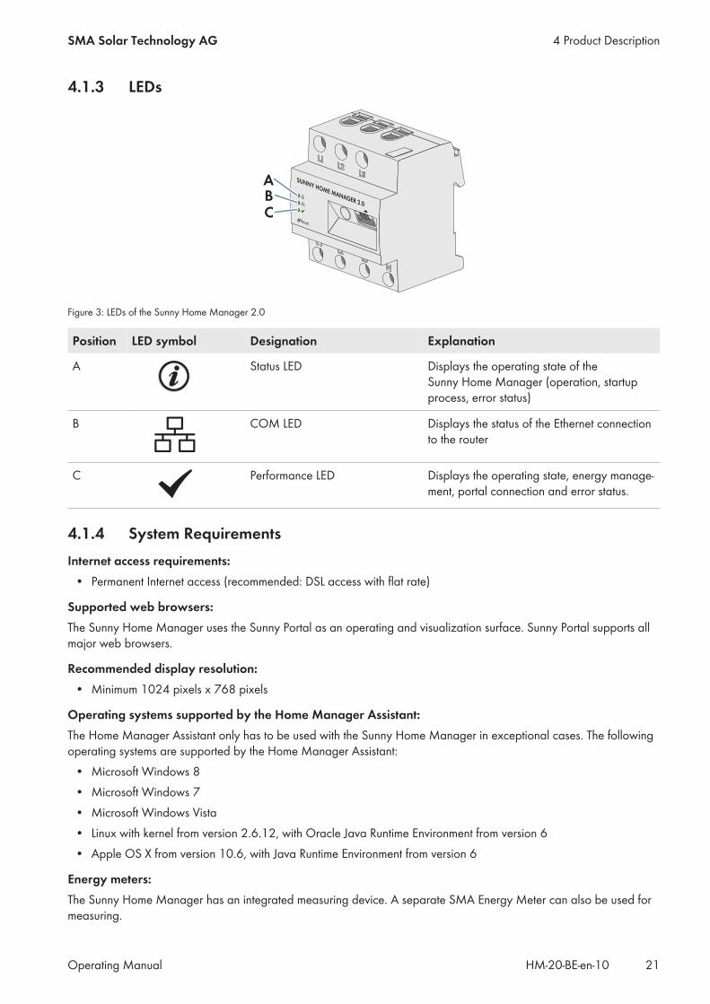
4.1.3 LEDs
Reset
SUNNY HOME MANAGER 2.0
ABC
Figure 3: LEDs of the Sunny Home Manager 2.0
Position LED symbol Designation Explanation
A Status LED Displays the operating state of theSunny Home Manager (operation, startupprocess, error status)
B COM LED Displays the status of the Ethernet connectionto the router
C Performance LED Displays the operating state, energy manage-ment, portal connection and error status.
4.1.4 System RequirementsInternet access requirements:
• Permanent Internet access (recommended: DSL access with flat rate)
Supported web browsers:The Sunny Home Manager uses the Sunny Portal as an operating and visualization surface. Sunny Portal supports allmajor web browsers.
Recommended display resolution:• Minimum 1024 pixels x 768 pixels
Operating systems supported by the Home Manager Assistant:The Home Manager Assistant only has to be used with the Sunny Home Manager in exceptional cases. The followingoperating systems are supported by the Home Manager Assistant:
• Microsoft Windows 8• Microsoft Windows 7• Microsoft Windows Vista• Linux with kernel from version 2.6.12, with Oracle Java Runtime Environment from version 6• Apple OS X from version 10.6, with Java Runtime Environment from version 6
Energy meters:The Sunny Home Manager has an integrated measuring device. A separate SMA Energy Meter can also be used formeasuring.
4 Product DescriptionSMA Solar Technology AG
Operating Manual 21HM-20-BE-en-10

SMA Solar Technology AG recommends using the integrated measuring device for measuring at the grid-connectionpoint. Measuring occurs bi-directionally. Thus, the purchased electricity and grid feed-in can be measured.For the function Limiting of the active power feed-in, at least one measurement at the grid-connection point isrequired. The Sunny Home Manager receives the PV generation data via the integrated measuring device or aseparate SMA Energy Meter depending on the connection type and configuration.
Network cable requirements:• Cable length between two nodes: max. 50 m with patch cable, max. 100 m with installation cable• Cross-section: at least 2 x 2 x 0.22 mm2 or at least 2 x 2 x 24 AWG• Cable category: Cat5, Cat5e, Cat6, Cat6a, Cat7• Cable shield: SF/UTP, S/UTP, SF/FTP, S/FTP• Plug type: RJ45 of Cat5, Cat5e, Cat6, Cat6a
4.2 Radio-controlled socketThe Sunny Home Manager supports the following radio-controlled sockets:
• Smart plug switches Edimax SP-2101W to firmware version 2.03 and Edimax SP-2101W V2 from firmwareversion 1.00
Conflicts when controlling the smart plug switchesBesides being controlled by the Sunny Home Manager, the Edimax smart plug switches can be controlled in otherways (e.g. via the Edimax app). By simultaneously controlling the smart plug switches via theSunny Home Manager and the Edimax app, conflicts can arise. This can result, for example, in the smart plugswitches being switched on and off unintentionally.
4.2.1 FunctionsThe radio-controlled socket supports load control in households with Sunny Home Manager.The radio-controlled socket carries out the following tasks:
• Implementation of Control Commands Issued by the Sunny Home Manager• Measurement of the Energy Consumption of the Connected Load
Implementation of Control Commands Issued by the Sunny Home ManagerThe Sunny Home Manager can switch the radio-controlled socket on and off. As a result, specific electrical devices canbe switched on if e.g. a lot of PV power is available.At which times the Sunny Home Manager switches the radio-controlled socket on or off depends on the configurationof the load and the current load planning configured in the Sunny Home Manager.
Measurement of the Energy Consumption of the Connected LoadThe radio-controlled socket measures the energy consumption of the connected loads and transmits the measuredvalues to the Sunny Home Manager. The Sunny Home Manager then transmits the values to Sunny Portal, where youcan visualize and control the energy flows in the household. You can also register your system in the Sunny Placescommunity portal and monitor your system, compare it with other systems and share knowledge and experiences withother PV system operators.
4 Product Description SMA Solar Technology AG
Operating ManualHM-20-BE-en-1022
4.3 Home appliances with intelligent communication interfaceThe following home appliances have been fitted with the energy management data protocol and have been testedwith SMA Smart Home:
• Stiebel Eltron heat pumps in conjunction with the Stiebel Eltron ISG web and the EMI software module (as ofOctober 2016)Integral systems
– LWZ 303/403 (Integral/SOL) from manufacture date 08/2008– LWZ 304/404 (SOL)– LWZ 304/404 Trend– LWZ 504
Air/water heat pumps– WPL 10 I, IK, AC– WPL 13/20 A basic– WPL 13-23 E / cool– WPL 34/47/57– WPL 15/25 A(C)(S)
Brine-water heat pumps– WPF 20-66 / HT– WPF 04-16 / cool– WPC 04-13 / cool
• Tecalor heat pumps in conjunction with ISG web and the EMI software module (as of October 2016)Integral systems
– THZ 303/403 (Integral/SOL) from manufacture date 08/2008– THZ 304/404 (SOL)– THZ 304/404 Trend– THZ 504
Air/water heat pumps– TTL 10 I, IK, AC– TTL 13/20 A basic– TTL 13-23 E / cool– TTL 34/47/57– TTL 15/25 A(C)(S)
Brine-water heat pumps– TTF 10-16 M– TTF 20-66 / HT– TTF 04-16 / cool– TTC 04-13 / cool
• Mennekes AMTRON® wall boxes Xtra and Premium models as charging stations for electric vehicles• Home appliances with EEBus interface (see technical information "SMA SMART HOME - Home appliance energy
management using EEBus")
4 Product DescriptionSMA Solar Technology AG
Operating Manual 23HM-20-BE-en-10

4.4 System StructureThe Sunny Home Manager has an integrated measuring device. Depending on the application, theSunny Home Manager is integrated and configured differently in the system (see Section 8.2, page 33):
PV system with SMA inverters and measurement at the grid-connection point (recommended)
SUNNY PORTAL
INTERNET
SUNNY HOME MANAGER 2.0
Ethernet
SUNNY BOY 1.5/2.5 SUNNY BOY TL
UTILITY GRID
PV MODULES
ROUTER
UTILITY METERFOR BILLINGPURPOSES
INTELLIGENTAPPLIANCE
via ETHERNET
RADIO-CONTROLLED SOCKETSvia WLAN
INTELLIGENTAPPLIANCEvia WLAN
APPLIANCE
WLANACDC
PV MODULES
PV system with inverters of other manufacturers and measurement at the grid-connection pointand the PV generation using a Sunny Home Manager and an SMA Energy Meter
SUNNY PORTAL
INTERNET
SMA ENERGY METER
Ethernet
SUNNY BOY 1.5/2.5SUNNY HOME MANAGER 2.0
UTILITY GRID
PV MODULES
ROUTER
UTILITY METERFOR BILLINGPURPOSES
INTELLIGENTAPPLIANCE
via ETHERNET
RADIO-CONTROLLED SOCKETSvia WLAN
INTELLIGENTAPPLIANCEvia WLAN
APPLIANCE
WLANACDC
PV MODULES
PV INVERTER
4 Product Description SMA Solar Technology AG
Operating ManualHM-20-BE-en-1024
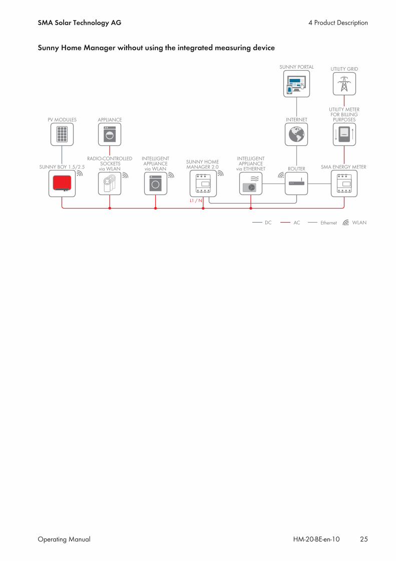
Sunny Home Manager without using the integrated measuring device
SUNNY PORTAL
INTERNET
SMA ENERGY METER
Ethernet
SUNNY BOY 1.5/2.5SUNNY HOME MANAGER 2.0
L1 / N
UTILITY GRID
PV MODULES
ROUTER
UTILITY METERFOR BILLINGPURPOSES
INTELLIGENTAPPLIANCE
via ETHERNET
RADIO-CONTROLLED SOCKETSvia WLAN
INTELLIGENTAPPLIANCEvia WLAN
APPLIANCE
WLANACDC
4 Product DescriptionSMA Solar Technology AG
Operating Manual 25HM-20-BE-en-10

5 Mounting
5.1 Requirements for Mounting the Sunny Home Manager☐ The mounting location must be indoors.☐ The Sunny Home Manager must be installed in a switch cabinet.☐ The mounting location must be protected against dust, moisture and corrosive substances.☐ The cable route from the mounting location to the router must not exceed a maximum length of 100 m.☐ A minimum distance of 1 m must be maintained from devices using the 2.4 GHz radio spectrum (e.g. WLAN
devices, microwave ovens). This will prevent reduced connection quality and data transmission speed.☐ The ambient conditions at the mounting location must be suitable for the operation of the Sunny Home Manager
(see Section 21, page 124).
5.2 Mounting the Sunny Home Manager on the Top-Hat RailRequirement:☐ The top-hat rail must be securely mounted in the switch cabinet.
Procedure:1. Press the Sunny Home Manager with the upper retainers into
the upper edge of the top-hat rail.
2. Hook the lower retainers into the lower edge of the top-hat rail.
5 Mounting SMA Solar Technology AG
Operating ManualHM-20-BE-en-1026

6 Preparing for Speedwire CommunicationIf the Sunny Home Manager is to communicate with other SMA devices via Speedwire, the Sunny Home Managerand the Speedwire devices must be in the same local network. Perform the following preparatory steps.
Inverters with Webconnect functionIf an inverter is already registered in Sunny Portal with the Webconnect function, the inverter cannot be added tothe Sunny Home Manager system in Sunny Portal.
• In order to be able to add the inverter to the Sunny Home Manager system in Sunny Portal, delete theinverter with Webconnect function from the Webconnect system in Sunny Portal or deactivate data receptionfor the inverter in the Webconnect system in Sunny Portal.
Requirements:☐ DHCP must be active on the router (see router documentation). If your router does not support DHCP, you can
configure the static network settings on the Speedwire device using SMA Connection Assist.☐ All UDP ports > 1024 on the router or modem must be open for outgoing connections. If there is a firewall
installed on the router or modem, you might have to adjust the firewall rules.☐ It must be possible for the outgoing router or modem connections to reach all Internet destinations (target IP,
target port). If there is a firewall installed on the router or modem, you might have to adjust the firewall rules.☐ On the router or modem with NAT (Network Address Translation), no port forwarding must be entered. Potential
communication problems can thus be prevented.☐ There must be no packet filtering or manipulation for SIP packets on the router or modem.☐ The routers and network switches with router function must forward the Multicast telegrams (telegrams with
destination address 239.0.0.0 to 239.255.255.255) required for the Speedwire connection to all nodes of theSpeedwire network.
☐ All network components used must support the IGMP protocol, minimum version 3 (IGMPv3) (see networkcomponent documentation).
Procedure:
1. Deactivating the BLUETOOTH communication of the invertersIf an inverter communicates simultaneously via Speedwire/WLAN and BLUETOOTH, data recording errorswill result. The Sunny Home Manager does not support communication with BLUETOOTH.
• For inverters with BLUETOOTH interface, set NetID 0 (see inverter- or BLUETOOTH Piggy-Backdocumentation). This deactivates communication via BLUETOOTH.
2. Connect the Speedwire devices to the router / network switch (see Speedwire device documentation). Make surethat the distance to the mounting location of the Sunny Home Manager is not too great, as theSunny Home Manager must later be connected to the same router/network switch.
6 Preparing for Speedwire CommunicationSMA Solar Technology AG
Operating Manual 27HM-20-BE-en-10

7 Connection
7.1 Connecting the Sunny Home Manager to the Router1. Connect the network cable to the network terminal of the
Sunny Home Manager. The network cable must be suitable forconnection to the Sunny Home Manager (see Section 4.1.4"System Requirements", page 21).
Reset
SUNNY HOME MANAGER 2.0
2. Connect the other end of the network cable to the router.
7.2 Connecting the Sunny Home Manager to the SMA Energy MeterThe SMA Energy Meter and the Sunny Home Manager must be connected to the same router.
Additionally required material (not included in the scope of delivery):☐ 1 network cable (see Section 4.1.4 "System Requirements", page 21)
Procedure:1. Connect the SMA Energy Meter to the router (see SMA Energy Meter installation manual).2. Connect the Sunny Home Manager to the router (see Section 7.1, page 28).
7.3 Replacing the SMA Energy Meter1. Write down the serial number of the new SMA Energy Meter. The serial number is to be found on the type label
of the SMA Energy Meter.2. Configure the new SMA Energy Meter in Sunny Portal (see Section 12.6 "Configuring the Energy Meter",
page 67).
7.4 Connecting a Smart ApplianceSome modern home appliances have an Ethernet connection with which the data of the device can be called up viathe local network. If there is an Internet connection via the network router, the manufacturers of household devices canuse this data for maintenance purposes, for example. Visualization and control of the household devices via mobiledevices (e.g. via app in the Smartphone) is also possible with this. If the manufacturer of the networked householddevices, in cooperation with SMA Solar Technology AG, has implemented a special data exchange protocol forenergy management in the device control, the Sunny Home Manager can control these loads directly via the localnetwork. For information on the supported products (see Section 2.3, page 11). The smart appliances send informationon the load type, the planned energy requirement, and the preferred operating time period to theSunny Home Manager. The Sunny Home Manager factors this information into its load control, and also taking theconfigured optimization targets in the context of load control into account, sends appropriate start and stop signals tothe loads.
Requirements:☐ The device must support the data exchange protocol defined by SMA Solar Technology AG.☐ The Sunny Home Manager must be located in the same local network as the device.
7 Connection SMA Solar Technology AG
Operating ManualHM-20-BE-en-1028
Additionally required material (not included in the scope of delivery):☐ 1 network cable (see Section 4.1.4, page 21)
Procedure:1. Connect the network cable to the device (see device documentation).2. Connect the other end of the network cable to the router or network switch.☑ The device is automatically recognized by the Sunny Home Manager. Once you have added the controllable
device to the Sunny Home Manager system via the configuration wizard in Sunny Portal, theSunny Home Manager will control the device automatically via the defined data exchange protocol.
PairingIn the case of EEBus compatible home appliances, a pairing must be performed. The new device will appear inSunny Portal only once the pairing has been completed successfully (see technical information: "SMA SMARTHOME - Home appliance energy management using EEBus").
7.5 Voltage supply terminal
7.5.1 Requirements for connecting the voltage supply
Danger to life due to electric shock if external disconnect switch is missingLethal voltages are present in the live components.
• Install an external disconnect switch between the product and the grid-connection point. The externaldisconnector must be close to the product and easily accessible.
Danger to life due to electric shockLethal voltages are present in the live components.
• Disconnect the connection point from voltage sources and make sure it cannot be reconnected.• Before performing any work on the product, disconnect the grid side from all voltage sources using the installed
disconnect switch.• Ensure that the conductors to be connected are de-energized.• Only use the product in a dry environment and keep it away from moisture.• Install the product in the switch cabinet only and ensure that the connection areas for the line conductors and
the neutral conductor are behind a cover or have contact protection.• Disconnect the product from voltage sources before cleaning and clean it with a dry cloth only.• Observe the prescribed minimum clearance between the network cable and live installation components, or use
suitable insulation.
Requirements:☐ The setpoints of the electric utility company must be observed.☐ At least the line conductor L1 and the neutral conductor must be connected. As a result, the
Sunny Home Manager is supplied with voltage.☐ When using fine stranded conductors, bootlace ferrules must be used.
Cable requirements:☐ Conductor cross-section without current transformer:10 to 16 mm²
7 ConnectionSMA Solar Technology AG
Operating Manual 29HM-20-BE-en-10

☐ Conductor cross-section with current transformer: see recommendations of the current transformer manufacturer
7.5.2 Connecting the Voltage Supply for Applications up to 63 A
L1 L2 L3 N
SUNNY HOME MANAGER 2.0
L1 L2 L3
Reset
L1 L2 L3
NL1 L2 L3
L1 L2 L3
L1 L2 L3 N
Router/Switch
SunnyPortal
Internet
WLANEthernet
OUT
IN
Household
Disconnect switch
Energy meter ofthe electric
utility company
Main breaker(three-phase)
Utility grid
Inverters
Sunny Home Manager 2.0as purchased electricity
and feed-in meter
L1, L2, L3: Line conductorN: Neutral conductorOUT: Meter output, load sideIN: Meter input, grid side
Figure 4: The following figure shows a connection example in TN and TT utility grids in the case of installation at the grid-connection point whenusing the integrated measuring unit.
Procedure:1. Disconnect the connection point from voltage sources and make sure it cannot be reconnected.2. Connect the line conductors to the Sunny Home Manager:
• When using the integrated measuring device and a three-phase utility grid, connect the line conductors L1,L2, L3 and N to the screw terminals at the input of the Sunny Home Manager. Open each screw terminalusing a cross-head screwdriver, insert the conductor into the contact terminal and tighten the screw using across-head screwdriver (torque: 2.0 Nm).
• When using the integrated measuring device and the single-phase utility grid, connect the line conductors L1and N to the screw terminals at the input of the Sunny Home Manager. Open each screw terminal using across-head screwdriver, insert the conductor into the contact terminal and tighten the screw using a cross-head screwdriver (torque: 2.0 Nm).
• When not using the integrated measuring device, connect the line conductor L1 and the neutral conductor tothe screw terminals at the input of the Sunny Home Manager. Open each screw terminal using a cross-headscrewdriver, insert the conductor into the contact terminal and tighten the screw using a cross-headscrewdriver (torque: 2.0 Nm).
7 Connection SMA Solar Technology AG
Operating ManualHM-20-BE-en-1030
• When using the integrated measuring device for measuring the PV generation output, connect theSunny Home Manager to the common connection point of all PV inverters in the household grid. AnSMA Energy Meter must be installed at the grid-connection point for this.
3. Retighten the screw terminals after six to eight weeks (torque: 2.0 Nm).
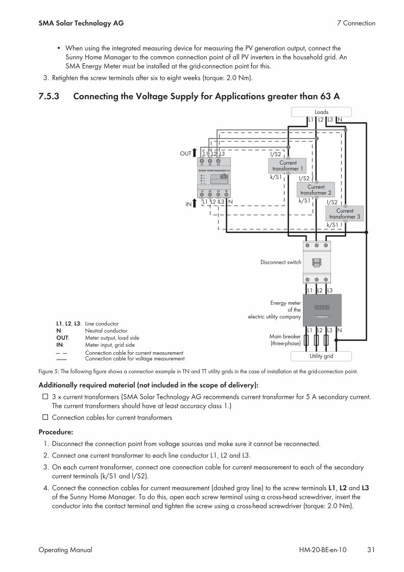
7.5.3 Connecting the Voltage Supply for Applications greater than 63 A
L1 L2 L3 N
L1 L2 L3 N
k/S1
l/S2
N
L1 L2 L3
k/S1
l/S2
k/S1
l/S2L1 L2 L3
OUT
IN
L1 L2 L3
L1 L2 L3 N
SUNNY HOME MANAGER 2.0
L1 L2 L3
Reset
Connection cable for voltage measurement
Currenttransformer 2
Currenttransformer 1
Loads
Disconnect switch
Energy meterof the
electric utility company
Main breaker(three-phase)
Utility gridConnection cable for current measurement
Currenttransformer 3
L1, L2, L3: Line conductorN: Neutral conductorOUT: Meter output, load sideIN: Meter input, grid side
Figure 5: The following figure shows a connection example in TN and TT utility grids in the case of installation at the grid-connection point.
Additionally required material (not included in the scope of delivery):☐ 3 x current transformers (SMA Solar Technology AG recommends current transformer for 5 A secondary current.
The current transformers should have at least accuracy class 1.)☐ Connection cables for current transformers
Procedure:1. Disconnect the connection point from voltage sources and make sure it cannot be reconnected.2. Connect one current transformer to each line conductor L1, L2 and L3.3. On each current transformer, connect one connection cable for current measurement to each of the secondary
current terminals (k/S1 and l/S2).4. Connect the connection cables for current measurement (dashed gray line) to the screw terminals L1, L2 and L3
of the Sunny Home Manager. To do this, open each screw terminal using a cross-head screwdriver, insert theconductor into the contact terminal and tighten the screw using a cross-head screwdriver (torque: 2.0 Nm).
7 ConnectionSMA Solar Technology AG
Operating Manual 31HM-20-BE-en-10

5. Connect the connection cables for voltage measurement (solid gray line) to the screw terminals L1, L2 and L3 atthe output of the Sunny Home Manager. To do this, open each screw terminal using a cross-head screwdriver,insert the conductor into the contact terminal and tighten the screw using a cross-head screwdriver (torque:2.0 Nm).
6. Connect the connection cables for voltage measurement L1, L2 and L3 (solid gray line) to the corresponding lineconductors L1, L2 and L3.
7 Connection SMA Solar Technology AG
Operating ManualHM-20-BE-en-1032

8 Commissioning
8.1 Testing the Connection to Sunny PortalThe Sunny Home Manager automatically establishes a connection to Sunny Portal. You can test whether there is aconnection to Sunny Portal if you proceed as described in the following.
Requirements:☐ DHCP must be active for the router (see router manual). If your router does not support DHCP, you can configure
the static network settings on the Sunny Home Manager using the Sunny Home Manager Assistant (seeSection 19.3 "Using the Sunny Home Manager Assistant", page 115).
☐ The Sunny Home Manager must be connected to the router (see Section 7.1 "Connecting theSunny Home Manager to the Router", page 28).
☐ The Sunny Home Manager must be supplied with voltage (see the installation manual of theSunny Home Manager).
Procedure:1. Check whether the status LED of the Sunny Home Manager is glowing green and whether the performance LED is
off.☑ The status LED of the Sunny Home Manager is glowing green and the performance LED is off. There is a
connection to Sunny Portal. You can register the Sunny Home Manager in Sunny Portal (see Section 8.2"Registering in Sunny Portal", page 33).
✖ The status LED or the performance LED is continuously flashing red?The Sunny Home Manager cannot establish the connection to Sunny Portal automatically. This is the case,for example, if there is a proxy server in your network or if your router does not support DHCP.
• Use the Sunny Home Manager Assistant (see Section 19.3 "Using the Sunny Home Manager Assistant",page 115).
2. Check whether the status LED of the Sunny Home Manager is glowing green and whether the performance LED isglowing green.☑ The connection to and registration in Sunny Portal have already been executed. Use your user data to log on
to Sunny Portal (see Section 8.3 "Logging In and Out of Sunny Portal", page 38).
8.2 Registering in Sunny PortalSunny Portal serves as the user interface of the Sunny Home Manager. Therefore, you must register theSunny Home Manager in Sunny Portal.
Requirements:☐ The PV system and all devices in the local network must be in operation and connected to the
Sunny Home Manager via a router/network switch.☐ The registration ID (RID) and the identification key (PIC) from the Sunny Home Manager type label must be
available.☐ NetID 0 must be set for Speedwire devices with integrated BLUETOOTH interface.☐ The status LED must glow green and the performance LED must be off.
8 CommissioningSMA Solar Technology AG
Operating Manual 33HM-20-BE-en-10

Procedure:1. Start the PV System Setup Assistant.2. Register as a new user in Sunny Portal.
orLog in to Sunny Portal as an existing user.
3. Create a Sunny Home Manager system in Sunny Portal.
Starting the PV System Setup AssistantThe PV System Setup Assistant is a step-by-step guide of the processes required for user registration and the registrationof Sunny Home Manager systems in Sunny Portal.
Procedure:1. Open www.SunnyPortal.com and select [PV System Setup Assistant].
orGo to www.SunnyPortal.com/Register.☑ The PV System Setup Assistant opens.
2. Select [Next].☑ The page User registration opens.
Register as a new user in Sunny Portal.1. Activate the field I am not yet registered and select [Next].2. Enter the necessary data for registration.3. Select [Next].
☑ After a few minutes you will receive an e-mail containing a link and your access data to Sunny Portal.✖ You did not receive an e-mail from Sunny Portal?
The e-mail may have been automatically redirected to your spam mail folder.• Check whether the e-mail is in the spam mail folder.
✖ You did not receive an e-mail from Sunny Portal?You may have stated a different e-mail address.
• Check whether the e-mail was sent to another e-mail address.• If the other e-mail address is an unknown address, restart the PV System Setup Assistant and register as a
new user again.4. Follow the link in the confirmation e-mail within 24 hours.
☑ Sunny Portal opens a separate window to confirm successful registration.5. Select [Next].6. The page Select PV system opens.
Log in to Sunny Portal as an existing user.
Requirement:☐ You must already have a PV system in Sunny Portal.
8 Commissioning SMA Solar Technology AG
Operating ManualHM-20-BE-en-1034
Procedure:1. Select the field I am already registered in Sunny Portal.2. Enter the e-mail address and the Sunny Portal password in the fields Sunny Portal e-mail address and
Password.3. Select [Next].☑ The page Select PV system opens.
Creating a Sunny Home Manager System in Sunny PortalAll devices with an identical password form a system. For this reason, a password used for all devices in a system iscalled a system password. The system password is the same as the device password for the user group Installer.
Requirements:☐ Either a uniform user-defined system password or the factory-set standard password 1111 must be set on all
Speedwire devices for the user group Installer. If necessary, set a uniform system password for all Speedwiredevices (see Sunny Explorer Help).
Procedure:1. Activate the field Create a new PV system and enter a system name (e.g. My Sunny Home Manager
system).2. In the window for entering the system password, enter the system password of the user role Installer:
• If the standard password 1111 is still set on all devices for the user group Installer, enter a new systempassword.
• If a different uniform password has already been set on all devices, enter this password as the systempassword.
• If a uniform password has not been set on all devices, set a uniform password for the user group Installerusing the Sunny Explorer software (see Sunny Explorer help) and enter this password in the PV System SetupAssistant as the system password.
3. Enter the system password again in the field Repeat password.4. Select [Next].
☑ The page Select devices opens.5. Enter the serial number of the Sunny Home Manager in the field PIC. Enter the registration ID of the
Sunny Home Manager in the field RID.6. Select [Identify].
☑ Sunny Portal searches for the Sunny Home Manager with the corresponding serial number and registrationID. The PV System Setup Assistant displays the correct Sunny Home Manager with a green tick.
✖ The PV System Setup Assistant cannot find any Sunny Home Manager with the entered serial number andregistration ID?
• See Troubleshooting (see Section 19 "Troubleshooting", page 112).
8 CommissioningSMA Solar Technology AG
Operating Manual 35HM-20-BE-en-10

7. Select [Next].☑ The Sunny Home Manager now searches for devices in the local network. After a maximum of ten minutes
the PV System Setup Assistant lists the serial numbers of any available devices in the local network.✖ The PV System Setup Assistant cannot establish a connection to the Sunny Home Manager and to the
Speedwire devices?orThe PV System Setup Assistant lists none or not all of the Speedwire devices in your PV system?
• Select [Refresh]. If the PV System Setup Assistant continues to list none or not all of the Speedwiredevices, see Troubleshooting (see Section 19.2 "Errors during Registration in Sunny Portal", page 112).
✖ The PV System Setup Assistant lists own and third-party devices?• See Troubleshooting (see Section 19 "Troubleshooting", page 112).
8. Activate the checkboxes of the devices you wish to add to the Sunny Home Manager system. Tip: You canidentify devices using the previously noted serial numbers.
9. Select [Add] to add the devices to the Sunny Home Manager system immediately.☑ The system password is transferred to the devices. This process can take several minutes. The devices are
then shown with a green tick.✖ Some devices are shown with the warning symbol?
Sunny Home Manager cannot access the devices. You may have entered an invalid system password or theconnection to the devices could not be established.
• See Troubleshooting (see Section 19 "Troubleshooting", page 112).10. Select [Skip forward] to add the devices to the Sunny Home Manager system at a later time and continue with
registration. Tip: You can add the devices to the Sunny Home Manager system as new devices after registration(see Section 14 "System Management", page 84).☑ The window Meter Configuration opens.
11. Select [Next].☑ The window Meter Configuration opens.
Configuring the Energy Meter1. In the Meter Configuration area, select the desired feed-in and purchased electricity meter or PV production
meter from the drop-down list:
Application Configuration
PV system with SMA inverters and measurement at thegrid-connection point
• Select the entry Internal Energy Meter in thePurchased Electricity and Grid feed-indropdown-list.
• Select the entry No energy meter in the PVGeneration drop-down list.
8 Commissioning SMA Solar Technology AG
Operating ManualHM-20-BE-en-1036

Application Configuration
PV systems with inverters of other manufacturers andmeasurement at the grid-connection point and PV gen-eration using a Sunny Home Manager and anSMA Energy Meter.
When connecting the Sunny Home Manager to thegrid-connection point and the SMA Energy Meter tomeasure the PV generation.
• Select the entry Internal Energy Meter in thePurchased Electricity and Grid feed-indropdown-list.
• Select the entry SMA Energy Meter xxx in thePV Generation drop-down list. Here, xxx is theplaceholder for the SMA Energy Meter serialnumber. If there are two SMA Energy Meters inthe PV system, select the desiredSMA Energy Meter.
PV systems with inverters of other manufacturers andmeasurement at the grid-connection point and PV gen-eration using a Sunny Home Manager and anSMA Energy Meter.
When connecting the Sunny Home Manager to thegrid-connection point and the Sunny Home Managerto measure the PV generation:
• Select the entry SMA Energy Meter xxx in thePurchased Electricity and Grid feed-in drop-down list. Here, xxx is the placeholder for theSMA Energy Meter serial number. If there are twoSMA Energy Meters in the PV system, select thedesired SMA Energy Meter.
• Select the entry Internal Energy Meter in thePV Generation drop-down list.
PV system with existing SMA Energy Meters • Select the entry SMA Energy Meter xxx in thePurchased Electricity and Grid feed-in drop-down list. Here, xxx is the placeholder for theSMA Energy Meter serial number. If there are twoSMA Energy Meters in the PV system, select thedesired SMA Energy Meter.
• Select the entry SMA Energy Meter xxx in thePV Generation drop-down list. Here, xxx is theplaceholder for the SMA Energy Meter serialnumber. If there are two SMA Energy Meters inthe PV system, select the desiredSMA Energy Meter.
2. Select [Next].☑ The page Extended PV System Properties opens.
Entering the PV System Data1. Enter the PV system data.2. Select [Next].
☑ The PV System Setup Assistant shows a summary of your entered data.3. Select [Finish].
☑ Sunny Portal confirms successful registration of the Sunny Home Manager system in a separate window.
8 CommissioningSMA Solar Technology AG
Operating Manual 37HM-20-BE-en-10

4. To go to the Sunny Home Manager system, select [To the PV system].☑ The Sunny Home Manager system opens.
5. Enter further PV system properties (see Section 16 "System Settings", page 96):• Add automatically recognized devices• Configure the load profiles of the automatically recognized devices• Enter the string configuration• Enter the operator data• Enter the PV array power• Enter the feed-in tariff, self-consumption tariff and electricity tariff• Configure settings for PV system monitoring
8.3 Logging In and Out of Sunny Portal
Logging into Sunny Portal
Requirement:☐ The Sunny Home Manager must be registered with the PV System Setup Assistant in Sunny Portal (see Section 8.2
"Registering in Sunny Portal", page 33).
Procedure:1. Go to www.SunnyPortal.com.2. In the Login area, enter the e-mail address in the field E-mail.3. Enter the Sunny Portal password in the field Password.4. Activate the SSL checkbox to transmit the encrypted login data.5. Activate the checkbox Remain logged in to stay logged in for your next Sunny Portal visits. This way, you stay
logged into Sunny Portal until you log out via the user interface.6. Select [Login].
Logging out of Sunny PortalWhen you log out of Sunny Portal user interface, your PV system will be protected against unauthorized access.
Procedure:• Select your user name in the header of the user interface and select [Logout].
8 Commissioning SMA Solar Technology AG
Operating ManualHM-20-BE-en-1038
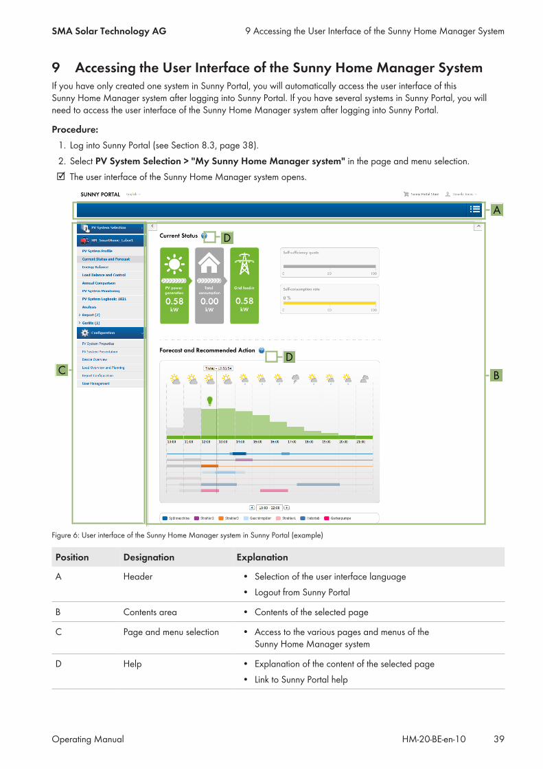
9 Accessing the User Interface of the Sunny Home Manager SystemIf you have only created one system in Sunny Portal, you will automatically access the user interface of thisSunny Home Manager system after logging into Sunny Portal. If you have several systems in Sunny Portal, you willneed to access the user interface of the Sunny Home Manager system after logging into Sunny Portal.
Procedure:1. Log into Sunny Portal (see Section 8.3, page 38).2. Select PV System Selection > "My Sunny Home Manager system" in the page and menu selection.☑ The user interface of the Sunny Home Manager system opens.
A
BCD
D
Figure 6: User interface of the Sunny Home Manager system in Sunny Portal (example)
Position Designation Explanation
A Header • Selection of the user interface language• Logout from Sunny Portal
B Contents area • Contents of the selected page
C Page and menu selection • Access to the various pages and menus of theSunny Home Manager system
D Help • Explanation of the content of the selected page• Link to Sunny Portal help
9 Accessing the User Interface of the Sunny Home Manager SystemSMA Solar Technology AG
Operating Manual 39HM-20-BE-en-10
10 Page and Menu Selection
10.1 System Selection and System ListThe following is required to display the menu item and page:☐ Your e-mail address must be assigned to more than one system in Sunny Portal.
System Selection Menu ItemUnder the menu item Select PV system, you can select the desired system (see Section 9, page 39).
System List PageThe following data is shown for each system:
• Nominal PV system power in kWp• Total yield so far• Total yield for the following time periods:
– Current day– Previous day– Current month
• Specific system yield (kWh/kWp) for the following time periods:– Current month– Current year
By default, the system list is sorted in ascending order in accordance with the specific system yield. You can also sortthe system list by other values and in descending order (see Section 11, page 63).
10.2 My Sunny Home Manager System
10.2.1 PV System ProfileSunny Portal compiles the PV system profile from information that you can enter in different Sunny Portal pages.The following information can be displayed in the PV system profile:
Information Configuration, see Section
Location Section 16.2, page 97
Operator Section 16.6, page 99
Commissioning Section 16.2, page 97
Nominal system power Section 16.4, page 98
Annual production Section 16.13, page 104
CO2 avoided Section 16.12, page 104
Modules Section 16.4, page 98
Tilt angle Section 12.10, page 70
Tracking
10 Page and Menu Selection SMA Solar Technology AG
Operating ManualHM-20-BE-en-1040
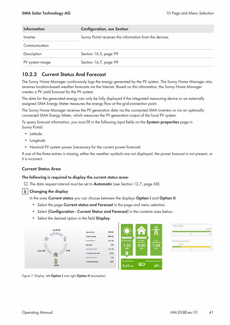
Information Configuration, see Section
Inverter Sunny Portal receives this information from the devices.
Communication
Description Section 16.5, page 99
PV system image Section 16.7, page 99
10.2.2 Current Status And ForecastThe Sunny Home Manager continuously logs the energy generated by the PV system. The Sunny Home Manager alsoreceives location-based weather forecasts via the Internet. Based on this information, the Sunny Home Managercreates a PV yield forecast for the PV system.The data for the generated energy can only be fully displayed if the integrated measuring device or an externallyassigned SMA Energy Meter measures the energy flow at the grid-connection point.The Sunny Home Manager receives the PV generation data via the connected SMA inverters or via an optionallyconnected SMA Energy Meter, which measures the PV generation output of the local PV system.To query forecast information, you must fill in the following input fields on the System properties page inSunny Portal:
• Latitude• Longitude• Nominal PV system power (necessary for the correct power forecast)
If one of the three entries is missing, either the weather symbols are not displayed, the power forecast is not present, orit is incorrect.
Current Status Area
The following is required to display the current status area:☐ The data request interval must be set to Automatic (see Section 12.7, page 68).
Changing the displayIn the area Current status you can choose between the displays Option I and Option II.
• Select the page Current status and Forecast in the page and menu selection.• Select [Configuration - Current Status and Forecast] in the contents area below.• Select the desired option in the field Display.
Figure 7: Display: left Option I and right Option II (examples)
10 Page and Menu SelectionSMA Solar Technology AG
Operating Manual 41HM-20-BE-en-10
Option I:The display Option I contains the following current data:
Designation Explanation
PV generation Currently generated power of your PV system
Grid feed-in Power that your system is currently feeding into the utility gridIf your system is generating more power than your household needs at the mo-ment or can be stored in the battery, the surplus power is fed into the utility grid.
Self-consumption Power that your household is currently drawing from your system and, if applica-ble, being stored into the battery from your system.
Purchased electricity Power that your household is currently drawing from the utility grid
Total consumption Power that your household is currently drawing from the utility grid
Self-consumption quota Current ratio of self-consumption to PV power
Battery discharging* Power that your household is currently drawing from the battery
Battery state of charge* Current state of charge of the battery in percent, in relation to the battery capac-ity
* Only displayed for PV systems with battery
Option II:The display Option I contains the following current data:
Designation Explanation
PV generation Currently generated power of your PV system
Consumption (Total consumption)
Power that your household is currently drawing from your system, the utility gridand, if applicable, your batteryThe colors visualize which portion of the consumption is currently made up of pur-chased electricity, direct consumption (PV system) and, if applicable, battery dis-charging.
Purchased electricity Power that your household is currently drawing from the utility grid
Grid feed-in Power that your system is currently feeding into the utility gridIf your system is generating more power than your household needs at the mo-ment or can be stored in the battery, the surplus power is fed into the utility grid.
Battery charging* Power that is being currently charged from your system into the battery
Battery discharging* Power that your household is currently drawing from the battery
10 Page and Menu Selection SMA Solar Technology AG
Operating ManualHM-20-BE-en-1042

Designation Explanation
Self-sufficiency quota Current ratio of internal power supply to total consumptionInternal power supply: Power that your household is drawing directly from yoursystem (direct consumption) and, if applicable, from the battery (battery discharg-ing).In systems without batteries, the self-consumption is the same as the internalpower supply.
Self-consumption quota Current ratio of self-consumption to PV powerSelf-consumption: the power that your household draws directly from your system(direct consumption) and, if applicable, the power that your system stores in thebattery (battery charging).
* Only displayed for PV systems with battery
Forecast and Recommended Action AreaThe Forecast and Recommended Action diagram visualizes the following information:
• Tariff for the electric current purchased from the utility grid• Expected PV power• Weather forecast for the current date (The data is not available in all countries.)• Scheduled time periods for operation of the loads
You can have a forecast displayed for up to 48 hours from the currently selected time.
10 Page and Menu SelectionSMA Solar Technology AG
Operating Manual 43HM-20-BE-en-10
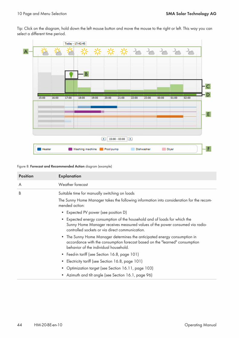
Tip: Click on the diagram, hold down the left mouse button and move the mouse to the right or left. This way you canselect a different time period.
A
B
DC
E
F
Figure 8: Forecast and Recommended Action diagram (example)
Position Explanation
A Weather forecast
B Suitable time for manually switching on loadsThe Sunny Home Manager takes the following information into consideration for the recom-mended action:
• Expected PV power (see position D)• Expected energy consumption of the household and of loads for which the
Sunny Home Manager receives measured values of the power consumed via radio-controlled sockets or via direct communication.
• The Sunny Home Manager determines the anticipated energy consumption inaccordance with the consumption forecast based on the "learned" consumptionbehavior of the individual household.
• Feed-in tariff (see Section 16.8, page 101)• Electricity tariff (see Section 16.8, page 101)• Optimization target (see Section 16.11, page 103)• Azimuth and tilt angle (see Section 16.1, page 96)
10 Page and Menu Selection SMA Solar Technology AG
Operating ManualHM-20-BE-en-1044

Position Explanation
C Expected PV power in accordance with the PV yield forecastThe Sunny Home Manager determines the PV power that can be expected in each case us-ing the weather forecast for the selected location and the "learned" behavior of the system.Tip: When you move the mouse over one of the bars, the following details for this time periodwill be displayed in a window:
• Estimated PV generation• Estimated consumption• Difference between the estimated PV generation and estimated consumption
D Tariff for the electric current purchased from the utility grid• Red: expensive• Green: good value
If you have only entered one electricity tariff, green is always displayed.• Other colors: electricity tariffs between the highest and the lowest electricity tariff
E View of the time periods for the planned operation of the loads (load prognosis)• The configured time periods are shown as colored, semi-transparent bars.• Time periods in which the loads were actually in operation or are going to be in
operation are shown as colored, solid bars.
F Loads legendThe legend shows which color is assigned to which load in the time-period view (E).
10.2.3 Energy BalanceRequirements for displaying the page:☐ The integrated measuring device or an externally assigned SMA Energy Meter must measure the energy flow at
the grid-connection point.The additionally required PV generation data will be determined either directly by the connected SMA inverters or canbe captured via an additional PV production meter in PV systems with Sunny Home Manager.
Display with BatteryIf a battery inverter is present in your system, you can select between the simplified view without battery data and thedetailed view with battery data.
• To display the data of the battery in the diagram and in the area Energy balance, activate the checkboxDetailed view.
• To avoid displaying the data of the battery in the diagram and in the area Energy Balance, deactivate thecheckbox Detailed view.
Showing and Hiding Diagram DataYou can show and hide the diagram data indicated in the legend by clicking on the respective entry in the legend.
10 Page and Menu SelectionSMA Solar Technology AG
Operating Manual 45HM-20-BE-en-10
The page Energy balance includes the following tabs:
Tab Content
Current Data in the Consumption diagram:• Current value of consumption: Power that your household is currently
drawing from your system (direct consumption or internal power supply forsystems without battery), from the utility grid (purchased electricity) and, ifapplicable, from the battery (battery discharging)
• Purchased electricity: Power that is currently being drawn by yourhousehold from the utility grid
• Internal power supply: Power that is currently being supplied to yourhousehold by your systemFor systems with battery, the power comes preferably directly from thesystem (direct consumption). If the power produced by the system is notsufficient, the remaining power is supplied by discharging the battery.
• Battery discharging (only displayed for systems with battery): Power thatyour household is currently drawing from the battery
• Direct consumption (only displayed for systems with battery): Power thatyour household is currently drawing from your system, without intermediatestorage in the battery
Current Data in the Generation diagram:• Current Power: Power that your system is currently generating• Self-consumption: Power that your household is currently drawing directly
from your system (direct consumption) and the power that your PV system iscurrently storing in the battery (battery charging)In systems without batteries, self-consumption is the same as internal powersupply.
• Battery charging (only displayed for systems with battery): Power thatyour system is currently storing in the battery
• Grid feed-in: Power that your system is currently feeding in to the utility gridIf your system is producing more power than your household needs at themoment or can be stored in the battery, the surplus power is fed into theutility grid.
10 Page and Menu Selection SMA Solar Technology AG
Operating ManualHM-20-BE-en-1046
Tab Content
Current Additional data:• Self-consumption rate: Current ratio of self-consumption to PV power• Direct consumption quota (only displayed for systems with battery):
Current ratio of direct consumption to PV power• Self-sufficiency quota: Current ratio of internal power supply to total
consumption• Limiting of the active power feed-in: Will only be displayed for
Sunny Home Manager systems if you have set active power feed-inlimitation for your PV system. A red line will indicate the maximum amount ofactive power that may be fed into If you have limited the active power feed-in to 0%, the red line runs directly on the x-axis of the diagram. Limitation ofthe active power feed-in to 0% is only supported by inverters that supportthe fallback function (fallback: in the event of a communication failurebetween the Sunny Home Manager and the inverter, the inverter reverts toan output power of 0 watts). For more information see the inverter manual atwww.SMA-Solar.com.
Day Data in the Consumption diagram:• Daily consumption: Energy that your household drew from your PV system
(direct consumption or internal power supply for systems without battery),the utility grid (purchased electricity) and, if applicable, the battery (batterydischarging) on the day selected
• Purchased electricity: Energy that your household drew from the utilitygrid on the day selected
• Internal power supply: Energy that was supplied to your household byyour PV system on the day selectedFor systems with battery, the energy comes preferably directly from thesystem (direct consumption). If the power produced by the system is notsufficient, the remaining power is supplied by discharging the battery.
• Battery discharging (only displayed for systems with battery): Energy thatyour household drew from the battery on the day selected
• Direct consumption (only displayed for systems with battery): Energy thatyour household drew directly from your PV system on the day selected,without intermediate storage in the battery
Day Data in the Generation diagram:• Daily yield: Energy that your system generated on the day selected• Self-consumption: Energy that your household drew directly from your
system on the day selected (direct consumption) and the energy that yoursystem stored in the battery (battery charging) on the day selected
• Battery charging (only displayed for systems with battery): Energy thatyour system stored in the battery on the day selected
• Grid feed-in: Energy fed by your system into the utility grid on the dayselected
10 Page and Menu SelectionSMA Solar Technology AG
Operating Manual 47HM-20-BE-en-10

Tab Content
Day Additional data:• Self-consumption rate: Ratio of self-consumption to daily yield• Direct consumption quota (only displayed for systems with battery): Ratio
of direct consumption to daily yield• Self-sufficiency quota: Ratio of internal power supply to daily consumption• Limiting of the active power feed-in: If you have set a limit to active
power feed-in for your system, a red line will indicate the maximum amountof active power permitted to be fed into the utility grid. If you have limitedthe active power feed-in to 0%, the red line runs directly on the x-axis of thediagram.
Month Data in the Consumption diagram:• Monthly consumption: Energy that your household drew from your system
(direct consumption or internal power supply for systems without battery),the utility grid (purchased electricity) and, if applicable, the battery (batterydischarging) during the month selected.
• Purchased electricity: Energy that your household drew from the utilitygrid during the month selected
• Internal power supply: Energy that was supplied to your household byyour PV system during the month selectedFor systems with battery, the energy comes preferably directly from thesystem (direct consumption). If the power produced by the system is notsufficient, the remaining power is supplied by discharging the battery.
• Battery discharging (only displayed for systems with battery): Energy thatyour household drew from the battery during the month selected
• Direct consumption (only displayed for systems with battery): Energy thatyour household drew directly from your PV system during the monthselected, without intermediate storage in the battery
Month Data in the Generation diagram:• Monthly yield: Energy that your PV system generated during the month
selected• Self-consumption: Energy that your household drew directly from your PV
system during the month selected (direct consumption) and the energy thatyour PV system stored in the battery (battery charging) during the monthselected
• Battery charging (only displayed for systems with battery): Energy thatyour PV system stored in the battery during the month selected
• Grid feed-in: Energy that your PV system fed into the utility grid during themonth selected.
Month Additional data:• Self-consumption rate: Ratio of self-consumption to monthly yield• Direct consumption rate (only displayed for systems with battery): Ratio of
direct consumption to monthly yield• Self-sufficiency quota: Ratio of internal power supply to monthly
consumption
10 Page and Menu Selection SMA Solar Technology AG
Operating ManualHM-20-BE-en-1048
Tab Content
Year Data in the Consumption diagram:• Annual consumption: Energy that your household drew from your system
(direct consumption or internal power supply for systems without battery),the utility grid (purchased electricity) and, if applicable, the battery (batterydischarging) during the year selected
• Purchased electricity: Energy that your household drew from the utilitygrid during the year selected
• Internal power supply: Energy that was supplied to your household byyour PV system during the year selectedFor systems with battery, the energy comes preferably directly from thesystem (direct consumption). If the power produced by the system is notsufficient, the remaining power is supplied by discharging the battery
• Battery discharging (only displayed for systems with battery): Energy thatyour household drew from the battery during the year selected
• Direct consumption (only displayed for systems with battery): Energy thatyour household drew directly from your PV system during the year selected,without intermediate storage in the battery
Year Data in the Generation diagram:• Annual yield: Energy that your PV system generated during the year
selected• Self-consumption: Energy that your household drew directly from your PV
system during the year selected (direct consumption) and the energy thatyour PV system stored in the battery (battery charging) during the yearselected
• Battery charging (only displayed for systems with battery): Energy thatyour PV system stored in the battery during the year selected
• Grid feed-in: Energy that your PV system fed into the utility grid during theyear selected.
Year Additional data:• Self-consumption rate: Ratio of self-consumption to annual yield• Direct consumption quota (only displayed for systems with battery): Ratio
of direct consumption to annual yield• Self-sufficiency quota: Ratio of internal power supply to yearly
consumption
10 Page and Menu SelectionSMA Solar Technology AG
Operating Manual 49HM-20-BE-en-10

Tab Content
Total Data in the Consumption diagram:• Total consumption Total amount of energy that your household has drawn
from your PV system (direct consumption or internal power supply forsystems without battery), from the utility grid (purchased electricity) and, ifapplicable, from the battery (battery discharging).
• Purchased electricity: Total amount of energy that your household drewfrom the utility grid so far.
• Internal power supply: Total amount of energy that has been supplied toyour household by your PV system so far.For systems with battery, the energy comes preferably directly from thesystem (direct consumption). If the power produced by the system is notsufficient, the remaining power is supplied by discharging the battery.
• Battery discharging (only displayed for systems with battery): Totalamount of energy that your household drew from the battery so far.
• Direct consumption (only displayed for systems with battery): Total energythat your household drew directly from your system so far, withoutintermediate storage in the battery
Total Data in the Generation diagram:• Total yield: Total amount of energy that your PV system has generated so
far• Self-consumption: Total amount of energy that your household drew
directly from your PV system so far (direct consumption) and energy thatyour PV system has stored in the battery (battery charging) so far.
• Battery charging (only displayed for systems with battery): Total energythat your system has stored in the battery so far
• Grid feed-in: Total amount of energy that your system has fed into the utilitygrid so far
Total Additional data:• Self-consumption rate: Ratio of self-consumption to total yield.• Direct consumption rate (only displayed for systems with battery): Ratio of
direct consumption to total yield• Self-sufficiency quota: Current ratio of internal power supply to total
consumption.
Difference between Internal Power Supply and Self-Consumption in PV Systems with BatteriesInternal power supply = the sum of power/energy that your household draws directly from your system (directconsumption) and the battery (battery discharging). The internal power supply therefore indicates from which sourceyour household is supplied with PV energy - from the PV system or from the battery.Self-consumption = the sum of the power/energy that your household draws directly from your system (directconsumption) and the power/energy that your system stores in the battery (battery charging). The self-consumptiontherefore indicates how the PV energy is consumed - via your household or via battery charging.In systems without batteries, self-consumption is the same as internal power supply.
10 Page and Menu Selection SMA Solar Technology AG
Operating ManualHM-20-BE-en-1050

10.2.4 Load Balance and ControlRequirements for displaying the page:☐ In the Sunny Home Manager system, loads must be available and configured which are connected to radio-
controlled sockets or which can be directly controlled by the Sunny Home Manager (see Section 13.2,page 72).
Tip: you can select the loads that are to be displayed in the diagram (see Section 11.3, page 64).Tip: the loads are displayed in different colors in the diagrams for better visualization. The assigned color can bechanged if necessary (see Section 13.3.2, page 75).This page consists of the following tabs:
Tab Content
Current The following is required to display the tab:☐ The data request interval must be set to Automatic (see Section 12.7,
page 68).The tab shows the following current data:
• Line at the bottom of the diagram: Live data on the flow of the consumedpower of each load in the selected display period
• Operating Mode: Operating mode of the radio-controlled socketThe button of the currently selected operating mode is highlighted in color.In addition, the LED status of the radio-controlled socket is displayed via anLED symbol.The operating mode can be changed accordingly using the buttons (seeSection 13.2.6, page 74). If the operating mode is controlled via theSunny Home Manager, (Automatic) appears behind the operating mode.
• Current value of consumption: Power currently being drawn by the load
Day • With selected view Stacking order view ( ):The lines below in the diagram show the progression of the power drawn byeach load on the selected day. Using the legend below the diagram, youcan show and hide the loads displayed in the diagram and change thestacking order of the loads in the diagram (see Section 11.3, page 64).
• With selected view Time period ( ):The light-colored bars show the time periods which you have configured forthe operation of the load.The dark-colored bars show the time periods in which the loads wereactually in operation.
– The symbols ▸ and ■ show the start and the stop point of operation.– If you move the mouse pointer over one of the dark-colored bars, the
energy consumed by the load in this time period is displayed in kWh.• In the table:
Daily consumption: Energy drawn by the load on the selected dayConfiguration: With the Configuration button [ ] you can configure theproperties of the load.
10 Page and Menu SelectionSMA Solar Technology AG
Operating Manual 51HM-20-BE-en-10
Tab Content
Month • In the diagram: Energy drawn by each load in the selected month in daysIf you move the mouse pointer over one of the bars in the diagram, awindow opens with the following information:
– The respective daily consumption of the loads operated on that day– The respective percentage of the daily consumption which was covered
by PV energy ( ), battery discharging ( ) or by the utility grid ( )• In the table:
Monthly consumption: Energy drawn by the load in the selected monthPV energy percentage: Percentage of the monthly consumption coveredby PV energyBattery discharging percentage: Percentage of the monthly consumptioncovered by battery dischargingPurchased electricity percentage: Percentage of the monthlyconsumption covered by the utility gridConfiguration: With the Configuration button [ ] you can configure theproperties of the load.
Year • In the diagram: Energy drawn by each load in the selected year in months• In the table:
Annual consumption: Energy drawn by the load in the selected yearPV energy percentage: Percentage of the annual consumption coveredby PV energyBattery discharging percentage: Percentage of the annual consumptioncovered by battery dischargingConfiguration: With the Configuration button [ ] you can configure theproperties of the load.
Total • In the diagram: Energy drawn by each load in the individual years• In the table:
Total consumption: Total energy drawn by the load so farPV energy percentage: Percentage of the total consumption drawn fromPV energyBattery discharging percentage: Percentage of the total consumptiondrawn from battery dischargingPurchased electricity percentage: Percentage of the total consumptiondrawn from the utility gridConfiguration: With the Configuration button [ ] you can configure theproperties of the load.
10.2.5 Energy and PowerRequirements for displaying the page:☐ No purchased electricity meter and no feed-in meter must be connected to the Sunny Home Manager.
The Sunny Home Manager receives the PV generation data via the connected SMA inverters or via an optionallyconnected PV production meter. The diagrams on the individual tabs show the energy yields only.
10 Page and Menu Selection SMA Solar Technology AG
Operating ManualHM-20-BE-en-1052
This page consists of the following tabs:
Tab Content
Day • PV power curve over the course of the day
Month • Total yield on the days of a month• Average expected yield*
Year • Total yield in the months of a year• Average expected yield*
Total • Total yield of the previous years• Average expected yield*
* Only displayed if activated on the page PV System Properties (see Section 16.13, page 104)
10.2.6 Annual ComparisonTab Content
Total yield • Yield development over the previous years• Average yield development over the previous years• Average expected yield*
Specific system yield The specific system yield is a key figure for describing the quality of asystem. System-specific factors such as location, tilt angle, shading,module and inverter types are taken into consideration to calculatethe specific system yield. The specific system yield enables you tocompare various systems at various locations.
• Development of the specific system yield of each previous year• Average development of the specific system yield of the
previous years• Average expected yield*
* Only displayed if activated on the page PV System Properties (see Section 16.13, page 104)
10.2.7 System MonitoringThe page can display the following information:
• System Configuration• Communication Monitoring• Inverter comparison
System configuration
Requirements for displaying the information:☐ You must have detected new devices with the configuration wizard but not yet added them to the
Sunny Home Manager system (see Section 14.1, page 84).You can access the configuration wizard via system configuration. Using the configuration wizard, you can add newdevices to the system or replace devices.
10 Page and Menu SelectionSMA Solar Technology AG
Operating Manual 53HM-20-BE-en-10

Communication MonitoringCommunication monitoring displays the current communication status between the Sunny Home Manager andSunny Portal. If the Sunny Home Manager does not communicate with Sunny Portal within the set time, Sunny Portalwill display an error and notify you by e-mail (see Section 15.4, page 93).The communication monitoring status is displayed with the following symbols:
Symbol Status Explanation
Deactivated Communication monitoring is not set (see Section 15.4, page 93).
OK Communication with Sunny Portal is OK. The time of last contact isdisplayed.
Error Communication with Sunny Portal is interrupted. The Details link pro-vides you with detailed information on the time of the last contact.The error will be displayed until it has been rectified.If the error is not corrected, Sunny Portal will send another e-mail re-minder each day for up to three days after the first e-mail was sent.
E‑mail reminder is activated Clicking the bell icon stops the sending of reminder e-mails for thecurrent error.If a new error occurs, the e-mail reminder will be sent again.
Inverter comparison
Requirements for displaying the information:☐ The system must contain at least two inverters.
The inverter comparison enables Sunny Portal to recognize possible yield losses. If the specific yield of an inverterdiffers significantly from the mean yield of all the inverters, Sunny Portal can notify you by e-mail (see Section 15.5,page 94).
Symbol Status Explanation
Deactivated The inverter comparison is not activated (see Section 15.5,page 94).
10 Page and Menu Selection SMA Solar Technology AG
Operating ManualHM-20-BE-en-1054

Symbol Status Explanation
OK The yields of the monitored inverters are within the configured range.The total yield of all inverters on the last day is displayed.
Error The specific yield is outside the tolerance for at least one monitoredinverter. You can access the following information via the Detailslink:
• Specific yield of the affected inverters• Average yield value of all monitored inverters
10.2.8 PV System LogbookThis page shows messages regarding the system status. The following message types are available:
• Info• Warning• Disturbance• Error
These messages help you to identify disturbances in your system, for example. The number of unconfirmed messages isshown after the colon of the page name in the menu.
Example: Display of Unconfirmed MessagesPV System Logbook: 5 means that there are five unconfirmed messages of the types Error, Disturbance orWarning.
You can filter messages and confirm that you have read the messages (see Section 15.2, page 89).
10 Page and Menu SelectionSMA Solar Technology AG
Operating Manual 55HM-20-BE-en-10

10.3 AnalysisOn the page Analysis, you can compare the power and yield values of individual inverters with one another or withthe complete system.
A
B
C
D
E
F
G
Figure 9: Analysis page (example)
Position Explanation
A Device Selection area
B Tabs
C Diagram preview*The diagram preview is divided into sections by lines. If you select a section in the diagram pre-view, the content is shown in the large diagram.
D Large diagramTip: If you move the mouse on to the diagram, the value from the area Details is shown next to thecursor.
E Total yield or Spec. total yieldDepending on the type of display selected in the area Device selection, the total yield or specifictotal yield will be displayed here.
10 Page and Menu Selection SMA Solar Technology AG
Operating ManualHM-20-BE-en-1056

Position Explanation
F Details area
G Logbook area* Not shown on the Total tab
Device Selection areaIn this area, you can select whether the complete system and/or individual inverters are to be displayed in the largediagram and in the Details area. Moreover, you can select whether absolute or specific values are to be displayed.
Select devices1. To display the values of the complete system, activate the checkbox Complete PV system in the area Device
selection.2. To display the values of individual inverters, perform the following steps:
• Select the area Device selection .☑ The area opens and the individual inverters are displayed.
• Activate the checkboxes for the desired inverters. Tip: If you activate the checkbox Select all devices, the checkboxes for all inverters will be activated.
Selecting the display type• In the area Device selection, next to Display type, select the desired option:
– Absolute: Shows the system yield (kWh) or the power (kW).– Specific: Shows the specific system yield (kWh/kWp) or the specific system power.
Tabs
Tab Explanation
Day Diagram preview:• Preview of diagrams with the progression of the PV system yields for
individual days Tip: If you move the cursor over a day in the diagram, the total yield of thePV system for this day is shown.
Large diagram:• Power value curve as 15-minute mean values of the selected devices for the
selected day• Bottom right in the diagram*: Total yield of the PV system for the selected
day
Week Diagram preview:• Preview of diagrams with the progression of the PV system yields for
individual weeks Tip: If you move the cursor over a week in the diagram, the total yield of thePV system for this week is shown.
Large diagram:• Power value curve as 15-minute mean values of selected devices for the
selected week.• Bottom right in the diagram*: Total yield of the PV system for the selected
week
10 Page and Menu SelectionSMA Solar Technology AG
Operating Manual 57HM-20-BE-en-10
Tab Explanation
Month Diagram preview:• Preview of diagrams with the yield values of the PV system for each month in
days Tip: If you move the cursor over a month in the diagram, the total yield of thePV system for this month is shown.
Large diagram:• Yield values of selected devices for the selected month in days• Bottom right in the diagram*: Total yield of the PV system for the selected
month
Year Diagram preview:• Preview of diagrams with the yield values of the PV system for each year in
months Tip: If you move the cursor over a year on a diagram, the total yield of thePV system for this year is shown.
Large diagram:• Yield values of the selected devices for the selected year in months• Bottom right in the diagram*: Total yield of the PV system for the selected
year
Total Large diagram:• Yield values of selected devices for individual years• Bottom right in the diagram*: Total yield of the PV system for all years
together* Only displayed if the checkbox Complete PV system is activated in Device selection
Details areaThis area contains the power values of the displayed diagram as 15-minute mean values.
Logbook areaThis area contains messages from selected devices and associated higher-level system messages.
10.4 Performance RatioRequirements for displaying the page:☐ A Sunny SensorBox must be installed in your Sunny Home Manager system. The Sunny SensorBox measures the
solar irradiation values at the installation site of the PV modules and makes this information available to theSunny Home Manager.
The performance ratio is a measure of the quality of a PV system that is independent of location (for information on theperformance ratio, see the technical information "Performance Ratio" at www.SMA-Solar.com).This page displays the following PV system data:
• Mean values of the performance ratio for the days of a month• Mean values of the performance ratio for the months of a year
10 Page and Menu Selection SMA Solar Technology AG
Operating ManualHM-20-BE-en-1058

10.5 System Report
Daily System ReportThis page displays the following inverter data:
• Table with daily yield, monthly yield, annual yield• Diagram with the development of the meter reading over the hours of a day
This page can be sent along with a Daily info report (see Section 15.3.2, page 91).
Monthly System ReportThis page displays the following inverter data:
• Table with monthly yield and annual yield• Diagram with the development of the meter reading over the days of a month
The page can be sent along with a Monthly info report (see Section 15.3.2, page 91).
10.6 DevicesA page with the respective inverter data for each inverter is displayed under the menu item Devices:
• Diagram with the development of the meter reading over the months of a year• Diagram with the mean power value for one day in hours
10.7 Configuration
10.7.1 System PropertiesThis page consists of the following tabs:
Tab Content
System data Displays the general data of the PV system. You can configure system settings using thistab (see Section 16, page 96).
Operator Displays the operator's contact information.
Parameters Displays the following data:• Feed-in tariff• Limitation of active power feed-in• Grid management services via Ethernet-based communication• Electricity tariff• Optimization target• CO2 avoided• Expected yield• If there is a Sunny SensorBox in your Sunny Home Manager system: performance
ratio
Data releases Displays to what extent SMA Solar Technology AGor third parties may use your data.You can edit the data releases using this tab (see Section 16.15, page 106).
10 Page and Menu SelectionSMA Solar Technology AG
Operating Manual 59HM-20-BE-en-10

10.7.2 System PresentationThe page PV system presentation offers you the following options:
• Send a link to your released pages to third parties (see Section 11.4.1, page 64).• Embed the page PV system profile in other websites.
10.7.3 Device OverviewThe page Device Overview includes the following tabs:
• Device Overview• Overview of New Devices
Device OverviewThis tab displays information on all the devices in your PV system.
A
B
C D E F G H I K
Figure 10: Device overview tab (example)
Position Designation Explanation
A Filter Text fields and drop-down lists for filtering the device overview (seeSection 12.1, page 66).
B Device list −
C Device name Device name
D Serial number Serial number of the device
E Product group Product group of the device, e.g. Sunny Home Manager,Sunny Boy 3000
F Data collection Displays whether the data of this device is to be used on yourSunny Portal pages (see Section 14.2, page 85).
G Monitoring Displays whether the communication monitoring or the inverter com-parison is activated ( ) or deactivated ( ) for the devices (see Sec-tion 10.2.7, page 53).
H Properties Opens tab with device properties (see Section 12.2, page 66).You can make settings on the devices using the Properties tab.
10 Page and Menu Selection SMA Solar Technology AG
Operating ManualHM-20-BE-en-1060

Position Designation Explanation
I Parameter Opens the Parameters tab with the device parameters (see Sec-tion 12.3, page 66).
K Logbook Opens the System Logbook tab with the messages for this device(see Section 15.2.1, page 89).
Overview of New DevicesVia this tab, you can add new devices to the system or replace devices using the configuration wizard (seeSection 14.1, page 84).
10.7.4 Load Overview and PlanningThe page displays information on all detected loads in your PV system and the time periods for which the loads arescheduled to operate.This page consists of the following areas:
• Load Overview and Planning• "Name of Load"
A B
C
D E F G
Figure 11: Load overview (example)
Position Designation Explanation
A Filter options Using the filter options, you can filter the list of loads. Selecting theoption Active loads will hide the loads that are currently not as-signed to a radio-controlled socket and therefore not controlled bythe Sunny Home Manager.
10 Page and Menu SelectionSMA Solar Technology AG
Operating Manual 61HM-20-BE-en-10

Position Designation Explanation
B Add loads Using this button, you can add further loads to theSunny Home Manager system.Smart appliances are recognized automatically by the configurationwizard and are displayed under Device Overview > Overview ofNew Devices. Following successful registration, the devices are dis-played on the page Load Overview and Planning in the areaLoad Overview.
C Load list List of loads which have been configured for use with theSunny Home Manager.
D Loads Symbol and name of the load
E Type of load Type of the load
F Status Status of the load = OK
Load is fully configured and receives data = Not active
Load is not assigned to a radio-controlled socket. = Load is not fully configured
G Configuration Opens the tab Name of Load, on which you can configure the loadproperties (see Section 13.3, page 75).
Load PlanningLoad planning provides a graphical overview of the scheduled time periods in which the active loads must beoperated (dark-colored bars) or can be operated (light-colored bars).
"Name of Load"You can access the tab "Name of Load" by going to the page Load overview and planning, area LoadOverview, and selecting the button Configuration [ ] in the line of the required load. On the tab "Name ofLoad", you can configure the properties of the load and time periods for the load. Depending on the selected loadtype, you can display and configure different load properties on the tab page (see Section 13.3, page 75).
10.7.5 Report ConfigurationThis page displays whether you have configured any reports to be e‑mailed by Sunny Portal, and if so which reporttypes (see Section 15.3, page 90).
10.7.6 User ManagementRequirements for displaying the page:☐ You must have the user role Installer or PV System Administrator (see Section 17.1, page 107).
This page displays all users created for the Sunny Home Manager system (see Section 17.2, page 108). You can alsoedit previously created users and, for example, change the user roles or delete users.
10 Page and Menu Selection SMA Solar Technology AG
Operating ManualHM-20-BE-en-1062

11 Page Settings
11.1 Diagram Settings
11.1.1 Setting the Display PeriodDepending on the diagram, there are different ways of setting the display period. The control element for setting thedisplay period can be found below each diagram.
Procedure:• If there is a time bar with a slider below the diagram, keeping the left mouse button pressed, click on the slider
and set the desired time period.• If there is a date and arrow icons below the diagram, set the date using the arrow icons or a calendar:
– To set the date using the arrow icons, scroll backwards using and scroll forwards using to select thedesired date.
– To set the date using the calendar, click on the date between the arrow icons and select the desired date.• If there are drop-down lists between the arrow icons, select the desired time period in the drop-down lists.
11.1.2 Saving Diagram DataYou can save diagram data as csv files.
Requirement:☐ You must have the user role Installer or PV System Administrator (see Section 17.1, page 107).
Procedure:1. If you can see the gearwheel icon on the right below the diagram, move the mouse pointer onto and select
in the drop-down menu.2. If there are two icons on the right below the diagram, select .3. Select [Save].4. Select the target directory.5. Select [Save].
11.1.3 Printing Diagram Data1. Move the mouse pointer onto on the right below the diagram.
☑ A drop-down menu opens.2. Select .3. Select [Print].4. Select the desired printer and select [Print].
11.1.4 Enlarging the View• If is visible on the right below the diagram, move the mouse pointer onto and select .• If there are two icons on the right below the diagram, select .
11.1.5 Showing and Hiding the LegendOn the inverter pages below the menu item Devices you can show and hide the diagram legend.
11 Page SettingsSMA Solar Technology AG
Operating Manual 63HM-20-BE-en-10
Procedure:1. Move the mouse pointer onto on the right below the diagram.
☑ A drop-down menu opens.2. To hide the legend, select .3. To show the legend, select .
11.2 Sorting the System ListBy default, the system list is sorted in ascending order in accordance with the specific system yield. You can also sortthe system list by other values and in descending order.
Procedure:• To sort the list by another value, click one of the other blue values in the header.• To sort the list in descending order, click on the blue value in the header again.
11.3 Showing, Hiding and Sorting LoadsUsing the legend below the diagram on the page Load Balance and Control, you can show and hide the loadsdisplayed in the diagram and change the stacking order of the loads in the diagram.
• To hide a load, click on the desired load. Loads that have been hidden are no longer displayed in the diagramand are shown in gray in the legend. You can display the load again by re-clicking on the load.
• To show all loads that have been hidden, select Show all below the legend.• To change the stacking order in the diagram, select the desired load and, holding down the left mouse button,
drag it to the desired position in the legend.
11.4 Publishing Pages
11.4.1 Releasing Pages for Viewing in Sunny PortalIf you release pages for viewing in Sunny Portal, other Sunny Portal users will be able to view the pages.You can release the following pages for viewing in Sunny Portal:
• PV system profile• Energy and power• Annual comparison
Requirement:☐ You must have the user role Installer or PV System Administrator (see Section 17.1, page 107).
Procedure:1. Select the desired page in the page and menu selection.2. In the Contents area, select [Configuration ‑ "Name of the page"].3. In the area Approval, activate the checkbox Also release page on www.sunnyportal.com.4. To send the page by e-mail, select Send the page by e-mail, enter the e-mail address of the recipient, select
[Send e-mail], and select .5. Select [Save].
11.4.2 Presenting Sunny Portal Pages on the InternetEach of your Sunny Portal pages has its own URL. Using these URLs, you can set a link to your Sunny Portal page onother websites.
11 Page Settings SMA Solar Technology AG
Operating ManualHM-20-BE-en-1064

You can link other websites to the following pages:• PV system profile• Energy and power• Annual comparison
Requirement:☐ You must have the user role Installer or PV System Administrator (see Section 17.1, page 107).
Procedure:1. Select the desired page in the page and menu selection.2. In the contents area, select [Configuration ‑ "Name of the page"].3. To view a preview of the page, select Open page in a new window.4. Copy the URL from the URL of the Page field onto the clipboard.5. Copy the URL from the clipboard to a program for creating websites (e.g. Microsoft Office Frontpage) or
integrate it into your own website by means of an inline frame.
11 Page SettingsSMA Solar Technology AG
Operating Manual 65HM-20-BE-en-10

12 Device Settings
12.1 Filtering the Device OverviewYou can find individual devices more easily if you filter the device overview.
Requirement:☐ You must be a Standard user, Installer or PV system administrator (see Section 17.1, page 107).
Procedure:1. Select Configuration > Device overview in the page and menu selection.2. Set one or more of the following filters:
Text field or drop-down list Explanation
Device name Complete name of the device or parts of the device name
Serial number Complete device serial number or parts of the serial number
Product group Device class sought, e.g. PV inverter, Sunny Home Manager.
Data collection • All: searches for activated and deactivated devices• Activated: only searches for activated devices• Deactivated: only searches for deactivated devices
3. Select [Refresh]. Tip: you can sort the devices in the device overview in ascending or descending order byclicking the blue entry in the table header (Device Name, Serial Number, Product Group, Data Collection).
4. To clear the filter, select [Reset].
12.2 Calling Up the Properties of a DeviceThe tab with the device properties displays information on each device. Depending on the device and the devicesettings, various device properties can be displayed on this tab.
Requirement:☐ You must be a Standard user, Installer or PV system administrator (see Section 17.1, page 107).
Procedure:1. Select Configuration > Device overview in the page and menu selection.2. In the row for the device and the Properties column, select .
12.3 Calling Up the Device ParametersThe parameters of a device are described in the respective device manual. The device parameters on this page canonly be read but not changed. If you want to change the parameters of devices in the Sunny Home Manager system,use the Sunny Explorer software (see Sunny Explorer help). You can obtain Sunny Explorer free of charge atwww.SMA-Solar.com. You cannot change parameters of the Sunny Home Manager via Sunny Explorer, but only viaSunny Portal.
Requirement:☐ You must be a Standard user, Installer or PV system administrator (see Section 17.1, page 107).
12 Device Settings SMA Solar Technology AG
Operating ManualHM-20-BE-en-1066
Procedure:1. Select Configuration > Device overview in the page and menu selection.2. In the device line and the Parameters column, select .
☑ You can read off the parameters in the parameter list.✖ The displayed parameters are not up to date?
Device parameters may have been changed using the Sunny Explorer software, but due to connectionproblems, the changes are not displayed in Sunny Portal.
• Update parameters (see Section 12.4, page 67).3. To display changes to the parameters, select in the column History.
12.4 Updating ParametersIt is advisable to update the parameters in the following case:
• Device parameters have been changed via the Sunny Explorer software, but the changes are not displayed in theSunny Portal.
Requirement:☐ You must have the user role Installer or PV System Administrator (see Section 17.1, page 107).
Procedure:1. Select Configuration > Device overview in the page and menu selection.2. Select [Update parameters].3. In the device line and the Parameters column, select .
☑ You can read off the current parameters in the parameter list.✖ The current parameters are still not displayed in the parameter list?
The time from which the updated parameters will be displayed depends on the configured data requestinterval (see Section 12.7, page 68). The Sunny Home Manger may not yet have transferred the updatedparameters to Sunny Portal.
• Call up the parameter list again later.
12.5 Reading Off the Software Package VersionRequirement:☐ You must be a Standard user, Installer or PV system administrator (see Section 17.1, page 107).
Procedure:1. Select Configuration > Device overview in the page and menu selection.2. In the device line and the Parameters column, select .
☑ You can read off the software package version in the parameter list.
12.6 Configuring the Energy MeterRequirement:☐ You must have the user role Installer or PV System Administrator (see Section 17.1, page 107).
12 Device SettingsSMA Solar Technology AG
Operating Manual 67HM-20-BE-en-10
Procedure:1. Call up the device properties of the Sunny Home Manager (see Section 12.2, page 66).2. Select [Edit].
☑ The menu for setting the device properties opens.3. In the Meter Configuration area, select the desired feed-in and purchased electricity meter or PV production
meter from the drop-down list (see Section 8.2, page 33).
12.7 Setting the Data Request IntervalThe data request interval defines how often the Sunny Home Manager sends data to and requests date fromSunny Portal.Sunny Portal can only display current data of the Sunny Home Manager and switch radio-controlled sockets if the datarequest interval is set to Automatic.SMA Solar Technology AG only recommends setting the data request interval to Hourly or Daily if your Internetconnection is established via a GSM modem. This way, depending on your GSM tariff, you will avoid additional costs.
Additional costs when using a cellular modemIf you set up the Internet connection using a cellular modem (e.g. a GSM modem), additional costs can be incurredas a result of frequent data requests, depending on the mobile service tariff.
• When using a cellular modem, additional costs can be prevented by setting the data request interval to Hourlyor Daily.
• If you are not using a cellular modem, set the data request interval to Automatic.
Requirement:☐ You must have the user role Installer or PV System Administrator (see Section 17.1, page 107).
Procedure:1. Call up the device properties of the Sunny Home Manager (see Section 12.2, page 66).2. Select [Edit].
☑ The menu for setting the device properties opens.3. In the area Data request interval , select the desired option:
Option Description
Automatic The Sunny Home Manager updates data on the pages Current Status andForecast and on the tabs Current within a few seconds. TheSunny Home Manager sends data that is displayed on other pages toSunny Portal within a few minutes (up to a maximum of 15 minutes). If loadsare controlled via radio-controlled sockets, you must activate the Automaticoption.
12 Device Settings SMA Solar Technology AG
Operating ManualHM-20-BE-en-1068

Option Description
Hourly The Sunny Home Manager sends data to and requests data from Sunny Por-tal hourly.Settings made via Sunny Portal are sent to the Sunny Home Manager within60 minutes.
Daily The Sunny Home Manager sends data to and requests data from Sunny Por-tal every 24 hours.Settings made on Sunny Portal are sent to the Sunny Home Manager within24 hours.
4. Select [Save].
12.8 Activating/Deactivating Automatic Software UpdatesIf the automatic software update is activated, Sunny Portal regularly checks whether there are update files for theSunny Home Manager or for the PV system devices. If there are update files, these are automatically downloaded andthe devices are updated.You can activate/deactivate the automatic software update for:
• Sunny Home Manager• PV system devices
By default, the automatic software update is activated for the Sunny Home Manager and the devices in the PV system.
Requirement:☐ You must have the user role Installer or PV System Administrator (see Section 17.1, page 107).
Activating/Deactivating the Automatic Software Update for the Sunny Home Manager1. Call up the device properties of the Sunny Home Manager (see Section 12.2, page 66).2. Select [Edit].
☑ The menu for setting the device properties opens.3. To activate the automatic software update, activate the checkbox Sunny Home Manager in the area
Automatically update software.4. To deactivate the automatic software update, deactivate the checkbox Sunny Home Manager in the area
Automatically update software .5. Select [Save].
Activating/Deactivating the Automatic Software Update for PV System Devices1. Call up the device properties of the Sunny Home Manager (see Section 12.2, page 66).2. Select [Edit].
☑ The menu for setting the device properties opens.3. To activate the automatic software update, activate the checkbox PV system devices in the area Automatically
update software.4. To deactivate the automatic software update, deactivate the checkbox PV system devices in the area
Automatically update software.5. Select [Save].
12 Device SettingsSMA Solar Technology AG
Operating Manual 69HM-20-BE-en-10
12.9 Entering Line ConductorsSunny Portal can display the line conductor to which each inverter is connected in the device properties. Enter the lineconductor you are looking for.
Requirement:☐ You must have the user role Installer or PV System Administrator (see Section 17.1, page 107).
Procedure:1. Select the device properties of the inverter (see Section 12.2, page 66).2. Select [Edit].
☑ The menu for setting the device properties opens.3. In the area Phase, activate the checkbox of the line conductor to which the inverter is connected.4. Select [Save].
12.10 Entering the PV Array PowerThe PV array power is the maximum power of the PV modules connected to one inverter.
Procedure:• Calculate the PV array power via the string properties (see Section 16.1, page 96).
or• Enter the PV array power manually
SMA Solar Technology AG recommends calculating the PV array power via the string properties. A string describes agroup of series-connected PV modules. Normally, a PV system is made up of multiple strings. Each string has specificproperties, such as deviation to south (azimuth) or the roof tilt angle.Entering the string properties provides the following advantages:
• Sunny Portal can determine the PV array power more precisely.• The Sunny Home Manager can deliver more exact yield forecasts and control loads more efficiently.
Enter the PV array power manuallyYou can find out the connected PV array power present on each inverter from your installer. Using the PV array power,Sunny Portal can calculate your nominal PV system power (see Section 16.4.2, page 98).
Requirement:☐ You must have the user role Installer or PV System Administrator (see Section 17.1, page 107).
Nominal PV system power required for limiting active power feed-inYou must enter the PV array power correctly to ensure limitation of the active power feed-in to the correct value(see Section 16.9, page 102). If there are changes to the installed PV array power, you will need to adjust thisvalue.
Procedure:1. Call up the inverter properties (see Section 12.2, page 66).2. Select [Edit].
☑ The menu for setting the device properties opens.3. In the area Generator capacity, enter the PV array power in the text field kWp.4. Select [Save].
12 Device Settings SMA Solar Technology AG
Operating ManualHM-20-BE-en-1070

12.11 Changing the Device NameThe serial number of the device is displayed as the default device name.
Requirement:☐ You must have the user role Installer or PV System Administrator (see Section 17.1, page 107).
Device name requirement:☐ The maximum length of the device name is 20 characters.
Procedure:1. Select the device properties of the device (see Section 12.2, page 66).2. Select [Edit].
☑ The menu for setting the device properties opens.3. Enter a device name in the Device Name or Name of Load text field.4. Select [Save].
12.12 Changing a Device DescriptionYou can enter an user-defined description for each device. The description of the device is displayed in DeviceProperties.
Requirement:☐ You must be a Standard user, Installer or PV system administrator (see Section 17.1, page 107).
Procedure:1. Call up the properties of the device (see Section 12.2, page 66).2. Select [Edit].
☑ The menu for setting the device properties opens.3. Enter a description in the text field Description.4. Select [Save].
12 Device SettingsSMA Solar Technology AG
Operating Manual 71HM-20-BE-en-10

13 Load Control
13.1 Information on Load ControlA load is a device in a household that is operated with electrical energy. To have a load controlled by theSunny Home Manager, you must establish a connection between the load and Sunny Home Manager. There arevarious options for doing this:
Connection option Explanation
Direct communication This connection option is only possible for the following devices:• Smart appliances which communicate via cable using a data exchange
protocol with the Sunny Home Manager (see Section 13.4, page 82)The load is connected via network cable or WLAN to the local network in whichthe Sunny Home Manager is also located. Thus, the load can automatically sendinformation on its energy requirement and consumption to the Sunny Home Man-ager and it can also receive switch-on and switch-off commands from theSunny Home Manager.
Switching and measuring via ra-dio-controlled sockets
In the Sunny Home Manager system, radio-controlled sockets can switch con-nected loads on and off. The radio-controlled sockets can also measure the en-ergy consumption of the connected loads and transmit this value to theSunny Home Manager. For this purpose, the radio-controlled sockets must be as-signed as devices to the Sunny Home Manager system (see Section 14.1,page 84).A load can either be permanently connected to the same radio-controlled socketor successively to alternate radio-controlled sockets. For each change, the loadmust be assigned to the new radio-controlled socket (see Section 13.3.11,page 78). If the load is not assigned to a radio-controlled socket, theSunny Home Manager cannot control this load or receive any consumption datafrom this load.Since the Sunny Home Manager does not receive any detailed data on loads ifthey are controlled via radio-controlled sockets, you will need to make additionalsettings in the load profiles depending on the respective load type. Thus, theSunny Home Manager can effectively schedule the loads in the load control andoptimize energy and cost savings.
13.2 Configuring Radio-Controlled Sockets
13.2.1 Safety when Configuring Radio-controlled Sockets
Danger to life by switching medical devicesUnintentional switching of medical devices can result in life-threatening situations.
• Do not connect any medical devices to the radio-controlled socket.
13 Load Control SMA Solar Technology AG
Operating ManualHM-20-BE-en-1072
Risk of injury and fire due to unintentional and unattended switching on of loadsLoads that are switched on via a radio-controlled socket unintentionally and while unattended can cause injuries andfires (e.g. an iron).
• Do not connect any loads to the radio-controlled socket that could endanger persons or cause damage ifunintentionally switched on.
Damage to loadsFrequently switching a load on and off can damage it.
• Ask the load manufacturer whether the load is suitable for control via a radio-controlled socket.• Configure the radio-controlled socket so that the load connected is not switched on or off more frequently than
specified by the load manufacturer.• Do not connect any loads to the radio-controlled socket if they require a continuous current supply.
13.2.2 Requirements when Configuring Radio-Controlled Sockets☐ The radio-controlled sockets must be registered in Sunny Portal (see Section 14.1, page 84).☐ In Sunny Portal, the data request interval must be set to Automatic (see Section 12.7, page 68).☐ You must be a Standard user, Installer or PV system administrator (see Section 17.1, page 107).
13.2.3 Activating/Deactivating Data CollectionYou can set whether or not the Sunny Portal is to collect data from the radio-controlled socket. If you would like tocontrol loads via the radio-controlled socket, you must activate data collection. If you deactivate data collection, noradio-controlled socket data is displayed in Sunny Portal and you cannot control any loads via the radio-controlledsocket.
Procedure:1. Call up the properties of the radio-controlled socket (see Section 12.2, page 66).2. Select [Edit].
☑ The menu for setting the device properties opens.3. To activate data collection, activate the checkbox Active.4. To deactivate data collection, deactivate the checkbox Active.
13.2.4 Selecting the LoadIn order that the radio-controlled socket can be controlled by the Sunny Home Manager, you must assign a load to it.You will first need to create a load profile for the load (see Section 13.3, page 75). If you have already installed aradio-controlled socket without assigning a load, you can subsequently assign this radio-controlled socket to therequired load when creating the load profile.
Procedure:1. Call up the properties of the radio-controlled socket (see Section 12.2, page 66).2. Select [Edit].
☑ The menu for setting the device properties opens.3. Select the connected load from the drop-down list Loads.
13 Load ControlSMA Solar Technology AG
Operating Manual 73HM-20-BE-en-10

State of the radio-controlled socket after load operationDepending on the load type, the radio-controlled socket is either switched on or switched off after load operation.
• Load is program-controlled: switched on• Load is not program-controlled: switched off
13.2.5 Entering the Device NameUsing the device name, you can identify the radio-controlled socket in the Sunny Home Manager system.SMA Solar Technology AG recommends keeping the device name that was automatically generated while registeringthe SMA radio-controlled socket. The serial number of the SMA radio-controlled socket is encoded in the automaticallygenerated device names. This allows the SMA radio-controlled socket to be identified by comparing with the typelabel.
Procedure:• Enter the desired device name in the text field Device name, for example, radio-controlled socket washing
machine basement.
13.2.6 Configuring the Operating ModeYou have the following options for setting the operating mode of the radio-controlled socket:
• Setting the Operating Mode via Sunny Portalor
• Setting the operating mode via the Sunny Portal mobile app
Setting the Operating Mode via Sunny Portal
Requirements:☐ The radio-controlled socket must be assigned to the connected load (see Section 13.2.4, page 73).☐ In Sunny Portal, the data request interval must be set to Automatic (see Section 12.7, page 68).☐ You must be a Standard user, Installer or PV system administrator (see Section 17.1, page 107).
Procedure:1. Select Load Balance and Control in the page and menu selection.2. Select the Current tab.3. In the table, in the column Operating mode, select the button for the desired operating mode next to the
required load.4. Select the desired operating mode:
Operating mode Explanation
automatically Control of the SMA radio-controlled socket by theSunny Home ManagerDepending on the current control command of theSunny Home Manager, the SMA radio-controlled socket is eitherswitched on or off in this mode.This operating mode cannot be set for the load type Measureonly
13 Load Control SMA Solar Technology AG
Operating ManualHM-20-BE-en-1074
Operating mode Explanation
Switch on No control of the SMA radio-controlled socket by theSunny Home ManagerThe SMA radio-controlled socket is switched on and switches tothe operating mode On. The connected load can draw electriccurrent.
Switch off No control of the SMA radio-controlled socket by theSunny Home ManagerThe SMA radio-controlled socket is switched off and switches tothe operating mode Off. The connected load cannot draw electriccurrent.
☑ After a short time, the selected operating mode is shown as activated on the Sunny Portal user interface.
13.3 Configuring Loads
13.3.1 Calling Up the Properties of a LoadThe tab "Name of Load" on page Load Overview and Planning displays the properties of the load. Dependingon the selected load type, you can display and configure different load properties on the tab.
Requirement:☐ You must be a Standard user, Installer or PV system administrator (see Section 17.1, page 107).
Procedure:1. Select Configuration > Load Overview and Planning in the page and menu selection.2. Select in the line of the load under the column Configuration.☑ The menu for setting the load properties opens.
13.3.2 Changing the Color Selection for LoadsThe loads are displayed in different colors in the diagrams for better visualization. The individually assigned color canbe changed if necessary.
Procedure:1. In the load list below the diagram, select the color field for the desired load.
orCall up the load properties (see Section 13.3.1, page 75), select [Edit] and then select the drop-down list Loadcolor.☑ A window for color selection opens.
2. Select the preferred color.3. Select [OK].
13.3.3 Selecting the Load Icon1. Call up the load properties (see Section 13.3.1, page 75).2. Select [Edit].3. Select the desired load icon in the Load icon drop-down list to use a standard load icon.4. To use your own load icon, perform the following steps:
13 Load ControlSMA Solar Technology AG
Operating Manual 75HM-20-BE-en-10

• Select [Upload load icon].☑ A file selection window opens.
• Select the desired file (permitted file formats: JPG, JPEG, PNG, GIF, BMP).• Select [Open].☑ The file is uploaded and then displayed in the drop-down list Load icon as the selected new load icon.
5. Select [Save].
13.3.4 Selecting the Load TypeThe settings that are possible for the load depend on which load type you select.
Procedure:1. Call up the load properties (see Section 13.3.1, page 75).2. Select [Edit].3. In the drop-down list Type of Load, select the desired load type:
Type of load Explanation
Self-configured You configure the connected load individually. Withthis type of load, you must also state whether the loadis program-controlled or if its operation can be inter-rupted at any time (see Section 13.3.5, page 76).Example of program-controlled load: dryerExample of load where operation can be interrupted:pond pump
Dishwasher The connected load is a dish washer.
Washing machine The connected load is a washing machine.
Energy monitoring (measuring only) Only the power consumption of the connected load isto be measured.
Stiebel Eltron WWK 300 The load connected is a heat pump from the Stiebel El-tron WWK electronic range.Some settings are not visible because they were set bythe manufacturer to predefined values specifically forthis device, and therefore cannot be changed.
Tecalor TTA 300 The load connected is a heat pump from the TecalorTTA electronic range.Some settings are not visible because they were set bythe manufacturer to predefined values specifically forthis device, and therefore cannot be changed.
Heating element The load connected is a heating element.
13.3.5 Selecting Program ControllabilityWith load type Self-configured, you must specify whether the load must run predefined programs or not.
13 Load Control SMA Solar Technology AG
Operating ManualHM-20-BE-en-1076

Procedure:• In the field Programmability, activate the required checkbox:
Setting Explanation
Yes After the start, the load runs through a defined program. Interrupting the load during thecourse of the program can affect the operation result and should therefore be avoided.Example: dryer
No The load always carries out the same function during operation. Multiple switching onand off per day does not cause any problems. The load does not have to run perma-nently - as long as a minimum operation time per day is achieved, interruption of opera-tion has no negative effect on the function being carried out.Examples: pond pump, heating element, water heater
13.3.6 Entering the Load NameUsing the load name, you can identify the loads in the Sunny Home Manager system.
Load name requirement:☐ The load name can have a maximum of 23 characters.
Procedure:• Enter a load name in the text field Name of Load, e.g. Washing machine basement.
13.3.7 Entering the Power ConsumptionThe power consumption is the average power typically required by a load for operation (see load manual).The Sunny Home Manager takes account of this value in the initial calculation of the required energy.Once the load provides measured values of its actual consumption during operation, the Sunny Home Manager candetermine a more precise power value after a learning phase. This way, the Sunny Home Manager graduallyimproves its load planning and increases energy and cost savings.
Procedure:• Enter the power of the load connected in the text field Power Consumption.
13.3.8 Entering the Maximum Program Operating TimeThe maximum program runtime is the time that a program-controlled load requires for its longest program. Themaximum program operating time defines the latest time at which a load must be switched on so that its longestprogram can be completed within the specified time limits.
Example: Maximum program operating time for a washing machineYou have defined a time slot from 10:00 a.m. to 6:00 p.m. for your washing machine (see Section 13.3.15,page 80), i.e. your washing machine's washing cycle must be completed by 6:00 p.m.The longest washing cycle of your washing machine lasts three hours. Therefore, enter at least three hours as themaximum program runtime when configuring the radio-controlled socket. In this case, the washing machine will startat 3:00 p.m. at the latest so that the longest washing cycle can be completed. If the selected washing cycle is ofshorter duration, the Sunny Home Manager still adheres to the maximum program runtime.
Requirement:☐ The connected load must be program-controlled (see Section 13.3.5, page 76).
13 Load ControlSMA Solar Technology AG
Operating Manual 77HM-20-BE-en-10
Procedure:Enter the maximum program operating time for the load connected in the Max. Program Operating Time text field(see the load manual).
13.3.9 Entering the Minimum Switch-On TimeThe minimum switch-on time is the minimum time that the load connected must remain switched on, for example, tocomplete its starting sequence or complete a work sequence.
Requirement:☐ The connected load must be program-controlled (see Section 13.3.5, page 76).
Delayed activation for some loads possibleSome loads may not start to operate immediately after switching on the radio-controlled socket, e.g. heat pumpsfor water storage tanks. Immediate activation can only be ensured for the radio-controlled socket, not for theconnected loads.
Procedure:• Enter the minimum switch-on time in the Minimum Switch-on Time text field. Take into consideration any
possible delays in starting the connected load.
13.3.10 Entering the Minimum Switch-Off TimeThe minimum switch-off time is the minimum time the connected load must remain switched off, for example, to preventoverheating or enable fault-free restarting.
Requirement:☐ The connected load must be program-controlled (see Section 13.3.5, page 76).
Procedure:• Enter the minimum switch-off time in the text field Minimum Switch-off Time.
13.3.11 Assigning Radio-Controlled SocketsFor the following reasons, you must assign the radio-controlled socket to the load to which it is connected:
• to have the load controlled by the Sunny Home Manager• to enable the Sunny Home Manager to save the data of the load
If the load was temporarily not assigned to any radio-controlled socket, corresponding data gaps will appear in theconsumption diagrams. The consumption data can always be called up on the load itself, even if the load is nowcontrolled by a different radio-controlled socket.
Procedure:• In the drop-down list Radio-controlled socket, select the radio-controlled socket to which the load is connected.
By default, no radio-controlled socket is assigned to the load.If the desired radio-controlled socket is already assigned to a different load, a "*" will be displayed in front of thename of the radio-controlled socket. In order to be able to reassign the radio-controlled socket, you must firstremove the assignment of the radio-controlled socket in the profile of the other load.
13 Load Control SMA Solar Technology AG
Operating ManualHM-20-BE-en-1078
13.3.12 Setting Measuring and Switching of the Radio-Controlled Socket• In the drop-down list Measuring and switching, select the required setting.
Setting Explanation
Radio-controlled socket is to measure and switch (intel-ligent power consumption)
The load draws electric current via the radio-controlledsocket.Using the consumption values measured by the radio-controlled socket, the Sunny Home Manager "learns"how much power the load typically consumes. This in-formation flows into the load control of theSunny Home Manager.
Radio-controlled socket is only to switch, not measure(fixed power consumption)
The load is switched e.g. via a relay which is con-nected to the radio-controlled socket.Using the connected relay, the radio-controlled socketswitches the load only in accordance with the configu-ration (time period) and the specifications of theSunny Home Manager.The value that is entered in the load profile in the fieldPower Consumption is the power consumption fac-tored in for planning the load control.
13.3.13 Setting Automatic Switch-OffIf the load has internal automatic switch-off, you must provide additional information in order that the radio-controlledsocket can detect whether the load is in operation or in standby mode.
Example: Heating element with automatic switch-offA heating element heats the water in a hot water tank. An integrated thermostat ensures that the heating element isswitched off automatically above a specific defined target temperature. The heating element is controlled via a radio-controlled socket.Within the time period defined for the heating element (see Section 13.3.15, page 80), it is switched on and offdepending on the availability of PV energy. If the automatic switch-off is activated and the water has not yet reachedthe set temperature at the end of the time period, the heating element can continue to draw electric current from theradio-controlled socket even though the time period has expired, until the target temperature is reached and theheating element has switched to standby mode on its own. The Sunny Home Manager recognizes the standby modeof the heating element and switches the radio-controlled socket off.
Requirement:☐ The load must not be program-controlled.
Procedure:1. In the field Load has internal automatic switch-off, activate the checkbox Yes.2. If required, in the text field Threshold for disconnection, adjust the preset threshold for the power consumption
in standby mode (refer to the load manual for information on power consumption during standby mode). Tip:Typically the threshold is approximately 50% of the average power consumption in operation.
3. If required, in the text field Detection time for disconnection recognition, adjust the preset time period forwhich the threshold of the power consumption must at least be exceeded in order to detect standby mode.
13 Load ControlSMA Solar Technology AG
Operating Manual 79HM-20-BE-en-10

13.3.14 Setting the Priority of the LoadThe priority determines which load should be switched on preferentially in the event of conflicts.The priority will only be considered for the following loads:
• Smart appliances with optional energy absorption. You will have already set the priority of these devices whenadding them to your Sunny Home Manager system via the configuration wizard.
• Loads connected to radio-controlled sockets for which you have set time periods of type Load can be switchedon (see Section 13.3.15, page 80). In the case of the time period type Load must be switched on, thepriority of the load does not have any effect, as the load is switched on in any event.
Example: Conflict between two loadsTwo loads, for which you have configured an optional time period in each case, should only be switched on ifexcess PV energy is available. As the amount of surplus PV energy is currently only sufficient for one load,however, the load with the higher priority is switched on. If both loads have the same priority, the load with thehigher level of consumption is switched on first.
Procedure:• Set the slider to the desired level.
13.3.15 Configuring the Time PeriodThe time period defines in which time period the Sunny Home Manager can or must switch the loads on. Theconfiguration of time periods is only possible for loads that are connected to radio-controlled sockets. You can setseveral time periods for each load.By default, a daily time period is set so that the load is switched on within the time period (load MUST be switchedon). The time periods configured are shown as colored bars in the Time period overview:
Color Explanation
Dark blue Compulsory time period
Light blue Optional time period
Red Invalid time period configurationIt is possible that the time period overlaps other, already configured time periods,or that the time period is too short for the entered minimum switch-on time of theload.
Shorter electrical endurance of the radio-controlled socket through the frequent switching of loadsThe more often the radio-controlled socket switches loads on and off, the shorter the electrical endurance of theradio-controlled socket.
• When setting time periods and device operating times, ensure that the radio-controlled socket does not haveto switch loads on and off unnecessarily (for the electrical endurance of the radio-controlled socket, seeSection "Technical Data" in the installation manual of the Sunny Home Manager).
Selecting the Time Period Type "Load Can Be Switched on" or "Load Must Be Switched On"This setting determines whether the load will definitely be switched on during the time period or only if certainconditions have been met.When you select the option Load can be switched on, you must subsequently configure the conditions for switchingon the load.
13 Load Control SMA Solar Technology AG
Operating ManualHM-20-BE-en-1080

Procedure:1. Select Configuration > Load Overview and Planning in the page and menu selection.2. In the line of the desired load, in the column Configuration, select .3. In the tab Name of Load, select the button [Edit].4. Select [Configure time period].5. If the load must definitely be switched on within the time period, select Load must be switched on (default
setting).6. If the load is only to be switched on under certain conditions within the time period, select Load can be
switched on.☑ The window Load will be switched on depending on opens.
7. Select the option Maximum permitted energy costs or the option Proportion of PV energy and set the sliderto the desired value (see Section Time Period Type "Load can be switched on": Configuring theConditions for Switching on the Load).
Time Period Type "Load Can be switched on": Configuring the Conditions for Switching on theLoadThe Sunny Home Manager can switch on the load depending on the proportion of PV energy or depending on themaximum permissible energy costs.
Optional time period: In some cases, the load is not switched onIf the configured proportion of PV energy is not attained or the maximum permissible energy costs are exceeded, it ispossible that the load will not receive any energy in the optional time period and the radio-controlled socket is notswitched on.
Proportion of PV energy:You can set the load to be switched on only if a certain minimum proportion of PV energy is available to operate theload. If the function Limiting of the active power feed-in is activated (see Section 16.9, page 102), you can alsoset the proportion of surplus PV energy that would otherwise be derated.
Example: Operating loads with at least 50% PV energyA washing machine is only to be switched on if 50% of the washing machine's energy requirement can be coveredby PV energy.
• The slider is set to 50%. Only if enough PV energy is available, the washing machine is switched on.
Maximum permitted energy costs:Maximum permissible energy costs You can set the maximum permissible energy costs for operation of the load. Theprice range of the slider is based on the highest and the lowest possible energy costs, e.g. the highest energy costs foroperation exclusively with expensive grid current and the lowest energy costs for operation exclusively with PV energy,the cost of which is calculated based on the feed-in tariff less the self-consumption tariff. In addition, if Limiting of theactive power feed-in is activated, surplus PV energy can be taken into account which is free, as it would otherwisebe derated.
Example: Operating the load exclusively with free energyA pond pump should only be switched on if there is more PV energy available than is permitted to be fed into theutility grid.
• The slider is set to 0 Euro/kWh. When enough surplus PV energy is available, the pond pump will be switchedon.
13 Load ControlSMA Solar Technology AG
Operating Manual 81HM-20-BE-en-10
Adding an Additional Time PeriodIf a load is not to run throughout the day, but rather at predefined intervals (e.g. pond pump), you must add severalconsecutive time periods for this day. Here, the number of time periods equates to the number of intervals in which theload is to run.
Procedure:1. Select Configuration > Load Overview and Planning in the page and menu selection.2. In the line of the desired load, in the column Configuration, select .3. In the tab Name of Load, select the button [Edit].4. Select [Configure time period].5. Select Add time period .
☑ A new time period with the corresponding number will be displayed in the Time period overview.6. Make the desired settings.7. Select [Accept].8. Select [Save].
Changing the Time Period1. Select Configuration > Load Overview and Planning in the page and menu selection.2. In the line of the desired load, in the column Configuration, select .3. In the tab Name of Load, select the button [Edit].4. Select [Configure time period].5. In the window Configure time period, make the desired changes for the time period.6. Select [Accept].7. Select [Save].
Deleting a Time PeriodYou cannot delete all the time periods for a load. At least one time period must always be configured for each load. Ifno radio-controlled socket is assigned to the load, however, the time period has no effect on the operation of the load.
Procedure:1. Select Configuration > Load Overview and Planning in the page and menu selection.2. In the line of the desired load, in the column Configuration, select .3. In the tab Name of Load, select the button [Edit].4. Select [Configure time period].5. Select for the desired time period and confirm the security prompt.6. Select [Accept].7. Select [Save].
13.4 Directly Controlling Loads
Controlling Smart AppliancesSome loads can communicate directly with the Sunny Home Manager. You will find a list of supported products in theSunny Home Manager installation manual.The loads send information via Ethernet or WLAN on the load type, the planned energy requirement, and thepreferred operating time period to the Sunny Home Manager.
13 Load Control SMA Solar Technology AG
Operating ManualHM-20-BE-en-1082
The Sunny Home Manager factors this information into its load control, and also taking the configured optimizationtargets you configured in the context of load control, sends appropriate start and stop signals to the loads.
Requirements:☐ You must have the user role Installer or PV System Administrator (see Section 17.1, page 107).☐ The load must support the data exchange protocol EEBus/SPINE or the data exchange protocol SEMP (see the
manual of the load and technical information at www.SMA-Solar.com).
Procedure:1. Connect the load to the local network and carry out the manufacturer-specific registration (see manual of the
load). The load must be located in the same local network as the Sunny Home Manager.☑ The Sunny Home Manager detects the new load in the local network.☑ The load is displayed on the page Device Overview > Overview of New Devices.
2. Add the load to the the Sunny Home Manager system. In the case of loads with optional energy consumption,you can also set the priority and the maximum permissible energy costs.☑ The new load is automatically displayed on the page Load Overview and Planning with the available
information and setting options.3. Change the load name if necessary (see Section 13.3.6, page 77).
13 Load ControlSMA Solar Technology AG
Operating Manual 83HM-20-BE-en-10
14 System Management
14.1 Adding or Replacing DevicesYou can add devices to your Sunny Home Manager system or replace devices.You have to capture the new device with the Sunny Home Manager.If you need to replace the Sunny Home Manager, you must use the PV System Setup Assistant (see Section 14.3,page 85).
General requirements:☐ You must have the user role Installer or PV System Administrator (see Section 17.1, page 107).
Requirement for SMA devices:☐ For the new SMA device, the default password 1111 for the user group Installer or the system password of the
existing system must be set (see Section 18.3, page 110).☐ The new device must be in operation.☐ The data request interval must be set to Automatic (see Section 12.7, page 68).
Device replacement: The old device must NOT be deleted, but deactivatedIf you delete the device that you wish to replace from Sunny Portal, all the device data is irretrievably deleted.
• To retain the data of the old device in Sunny Portal, do not delete the old device, but deactivate it (seeSection 14.2, page 85).
• Add the new device as an additional device to the Sunny Home Manager system (system extension).
Smart appliances cannot be replacedSmart appliances which communicate via a data exchange protocol with the Sunny Home Manager cannot bereplaced in Sunny Portal.
• To retain the data of the old load in Sunny Portal, do not delete the old load, but deactivate it (seeSection 14.2, page 85).
• Add the new load as an additional device to the Sunny Home Manager system (system extension).
Password for Edimax smart plug switchesAll Edimax smart plug switches in the system must have the same password. If there are different passwords forthe smart plug switches, the Sunny Home Manager cannot control all smart plug switches.
Procedure:1. Go to www.SunnyPortal.com.2. Log into Sunny Portal (see Section 8.3, page 38).3. Select PV System Selection > "My Sunny Home Manager system" in the page and menu selection.4. If you would like to replace a device in Sunny Portal, deactivate the old device (see Section 14.2, page 85).5. Select Device overview > Overview of new devices in the page and menu selection.6. Select [Refresh devices]. The Sunny Home Manager then searches for new devices in the local network.
☑ After a maximum of one minute, all new devices are displayed.✖ None or not all of the new devices are displayed?
An error has occurred.• Eliminate the error (see Section 19, page 112).
7. To add a device, select in the line of the device.
14 System Management SMA Solar Technology AG
Operating ManualHM-20-BE-en-1084
8. To replace a device, select in the line of the new device.☑ The Sunny Home Manager connects to the new device. Page 2 of the configuration wizard opens.✖ Page 2 of the configuration wizard does not open but the error message Connection Failed is displayed?
A password other than 1111 or other than the system password of the existing system is set for the new SMAdevice.
• Temporarily change the system password of the existing system to the password of the new SMA device(see Section 18.3, page 110).
9. Follow the instructions of the configuration wizard.
10. Replacing an inverterIt can take up to 20 minutes to replace an inverter using the configuration wizard.
☑ The new SMA device is displayed under Configuration > Device overview.☑ The new device connected via Ethernet is displayed under Configuration > Load overview and
planning.11. If you have just changed the system password of the existing system to the password of the new SMA device,
reset the old system password (see Section 18.3, page 110).12. If the new device is a radio-controlled socket, configure the radio-controlled socket (see Section 13.2, page 72).
Remember that the load connected to the radio-controlled socket must be configured first (see Section 13.3,page 75).
14.2 Activating/Deactivating DevicesIn the following cases, you must deactivate devices in Sunny Portal:
• You have removed a device from your PV systemor
• You no longer wish to display a device in Sunny Portalor
• You would like to replace the device in Sunny Portal by another device (see Section 14.1, page 84).The data of the deactivated device is retained in Sunny Portal.
Requirement:• You must have the user role Installer or PV system administrator (see Section 17.1, page 107).
Procedure:1. Select the device properties of the device (see Section 12.2, page 66).2. Select [Edit].
☑ The menu for setting the device properties opens.3. To deactivate the device in Sunny Portal, deactivate the checkbox Active in the area Data collection.4. To activate the device in Sunny Portal, activate the checkbox Active in the area Data collection.5. Select [Save].
14.3 Replacing the Sunny Home ManagerRequirements:☐ The NetID of the PV system must be set in the Sunny Home Manager (see the installation manual of the
Sunny Home Manager).☐ The new Sunny Home Manager must be connected to the router (see the installation manual of the
Sunny Home Manager).
14 System ManagementSMA Solar Technology AG
Operating Manual 85HM-20-BE-en-10

☐ The new Sunny Home Manager must be supplied with voltage (see the installation manual of theSunny Home Manager).
☐ You must be a system administrator (see Section 17.1, page 107).
Procedure:1. Open www.SunnyPortal.com and select PV System Setup Assistant.
orGo to www.SunnyPortal.com/Register.☑ The PV System Setup Assistant opens.
2. Select [Next].☑ The page User registration opens.
3. Activate the checkbox I am already registered in Sunny Portal.4. Enter the e-mail address and the Sunny Portal password in the fields E-mail address and Password.5. Select [Next].
☑ The page Select PV system opens.6. Activate the field Add or replace devices.7. Select in the line of the Sunny Home Manager system for which you want to replace the
Sunny Home Manager.8. Select [Next].
☑ The page Select devices opens.9. Enter the serial number of the Sunny Home Manager in the field PIC. Enter the registration ID of the
Sunny Home Manager in the field RID.
10. Reading off the serial number and registration IDYou can read off the serial number and the registration ID at the following locations:
• On the type label at the back of the Sunny Home Manager• On the label included in the delivery
11. Select [Identify].☑ Sunny Portal checks whether the serial number and registration ID correspond to the connected
Sunny Home Manager.✖ The PV System Setup Assistant cannot find any Sunny Home Manager with the serial number and registration
ID?An error has occurred.
• Eliminate the error (see Section 19, page 112).12. Select [Next].13. Select [Finish].
14.4 Reassigning the Sunny Home Manager to the Sunny Portal Systemafter the Reset
If you have performed a complete reset of the Sunny Home Manager, you must reassign the Sunny Home Manager toyour Sunny Home Manager system in Sunny Portal. Otherwise, Sunny Portal will not accept any data from theSunny Home Manager.
14 System Management SMA Solar Technology AG
Operating ManualHM-20-BE-en-1086

You have the following options for reassigning the Sunny Home Manager to your Sunny Home Manager system:• Reassigning the Sunny Home Manager via the PV System Setup Assistant
or• Reassign the Sunny Home Manager via the Sunny Portal access (see Section 14.3, page 85)
Reassigning the Sunny Home Manager to the Sunny Home Manager System via the PV SystemSetup Assistant
Requirement:☐ You must be a system administrator (see Section 17 "User Management", page 107).
Procedure:1. Open www.SunnyPortal.com and select [PV System Setup Assistant].
orGo to www.SunnyPortal.com/Register.☑ The PV System Setup Assistant opens.
2. Select [Next].☑ The page User registration opens.
3. Activate the checkbox I am already registered in Sunny Portal.4. Enter the e-mail address and the Sunny Portal password in the fields E-mail address and Password.5. Select [Next].
☑ The page Select PV system opens.6. Activate the field Add or replace devices.7. In the line of the Sunny Home Manager system to which you would like to reassign the Sunny Home Manager,
select .8. Select [Next].
☑ The page Select devices opens.9. Enter the serial number of the Sunny Home Manager in the field PIC. Enter the registration ID of the
Sunny Home Manager in the field RID.
10. Reading off the serial number and registration IDYou can read off the serial number and the registration ID from the type label on the rear of theSunny Home Manager.
11. Select [Identify].☑ Sunny Portal checks whether the serial number and registration ID correspond to the connected
Sunny Home Manager.✖ The PV System Setup Assistant cannot find any Sunny Home Manager with the serial number and registration
ID?An error has occurred.
• Eliminate the error (see Section 19 "Troubleshooting", page 112).12. Select [Next].13. Select [Finish].
14 System ManagementSMA Solar Technology AG
Operating Manual 87HM-20-BE-en-10

14.5 Deleting a Device from Sunny PortalRequirement:☐ You must have the user role Installer or PV System Administrator (see Section 17.1, page 107).
Device data is irretrievably deletedIf you delete a device, all the data of that device is irretrievably deleted.
• Check whether it is sufficient to deactivate the device (see Section 14.2, page 85).
Procedure:1. Select the device properties of the device (see Section 12.2, page 66).2. Select [Edit].3. Select [Delete].
☑ A window with a security prompt opens.4. To irretrievably delete the device, select [Delete].
14.6 Deleting the Sunny Home Manager SystemRequirement:☐ You must have the user role Installer or PV System Administrator (see Section 17.1, page 107).
If you delete the Sunny Home Manager system, the system and its data will be permanently deleted.
Procedure:1. Select Configuration > PV system properties in the page and menu selection.2. Select [Edit].3. In the PV system data area, select [Irretrievably delete PV system].
☑ A security prompt opens.4. Select [Yes] to permanently delete the Sunny Home Manager system.
Assigning the Sunny Home Manager to another systemTo enable assignment of the Sunny Home Manager to another system, you must perform a complete reset of theSunny Home Manager (see the installation manual of the Sunny Home Manager).
14 System Management SMA Solar Technology AG
Operating ManualHM-20-BE-en-1088

15 System Monitoring
15.1 PV System Monitoring OptionsWith the Sunny Home Manager, you can carry out essential monitoring of your PV system.
Monitoring of: Option in Sunny Portal See
Events of the system PV System LogbookYou can view messages regardingevents of your PV system.
Section 15.2, page 89
Report configurationYou receive e-mails with the events ofyour system.
Yield, power, and CO2 avoided Report configurationYou receive e-mails with your plantdata.
Section 15.3, page 90
Inverter yields Inverter comparisonYou will be notified by e-mail if thespecific yield of an inverter is outsidethe set tolerance range.
Section 15.5, page 94
Communication between theSunny Home Manager and theSunny Portal
Communication monitoringYou are notified by e-mail if theSunny Home Manager does not com-municate with Sunny Portal within theset time.
Section 15.4, page 93
If you require more detailed system monitoring functions and more comprehensive data storage, you have the optionof activating additional functions via the SMA Online Store subject to a fee. If you do not yet have access to theSMA Online Store, please contact your distributor.
15.2 PV System Logbook
15.2.1 Calling Up and Filtering MessagesMessages help you, for instance, to detect disturbances in your PV system. The following message types are available:
• Info• Warning• Disturbance• Error
Requirement:☐ You must be a Standard user, Installer or PV system administrator (see Section 17.1, page 107).
Calling Up Messages• Select PV System Logbook in the page and menu selection.
Filtering MessagesYou can filter messages in the system logbook to only call up certain messages.
15 System MonitoringSMA Solar Technology AG
Operating Manual 89HM-20-BE-en-10
Procedure:1. Select PV System Logbook in the page and menu selection.2. To filter messages, set one or more of the following filters:
Input field or drop-down list Explanation
Go to • Enter the date for the messages you would like to display. Tip: click thecalendar icon and select a date in the calendar.
Status • To display all unconfirmed messages, select Not approved.• To display all confirmed messages, select Approved.• To display all messages, select All.
System/Devices • To display the messages in Sunny Portal, the Sunny Home Managersystem and the devices, select All.
• To display Sunny Portal messages, select Portal.• To display messages of the Sunny Home Manager system, select PV
System.• To display messages of specific devices, select the respective device (e.g.
SB 4200TL).
Number per page • Select the number of messages that you would like to see.
Type • To display messages of a specific type, activate the appropriatecheckbox Info, Warning, Failure or Error.
15.2.2 Confirming MessagesYou can confirm messages in order to mark them as read. This will help you to differentiate between old and newmessages.
Requirement:☐ You must be a Standard user, Installer or PV system administrator (see Section 17.1, page 107).
Procedure:1. Select PV System Logbook in the page and menu selection.2. To confirm messages individually, select in the message line and the column Confirmed.3. To confirm several messages, mark the required messages:
• To select individual messages, activate the relevant checkboxes on the left of the messages.• To select all messages, activate the checkbox Select all.
4. Select [Execute].
15.3 Reports
15.3.1 Report OverviewReports are documents containing system data or system events. You can have the reports sent by e-mail fromSunny Portal.
15 System Monitoring SMA Solar Technology AG
Operating ManualHM-20-BE-en-1090
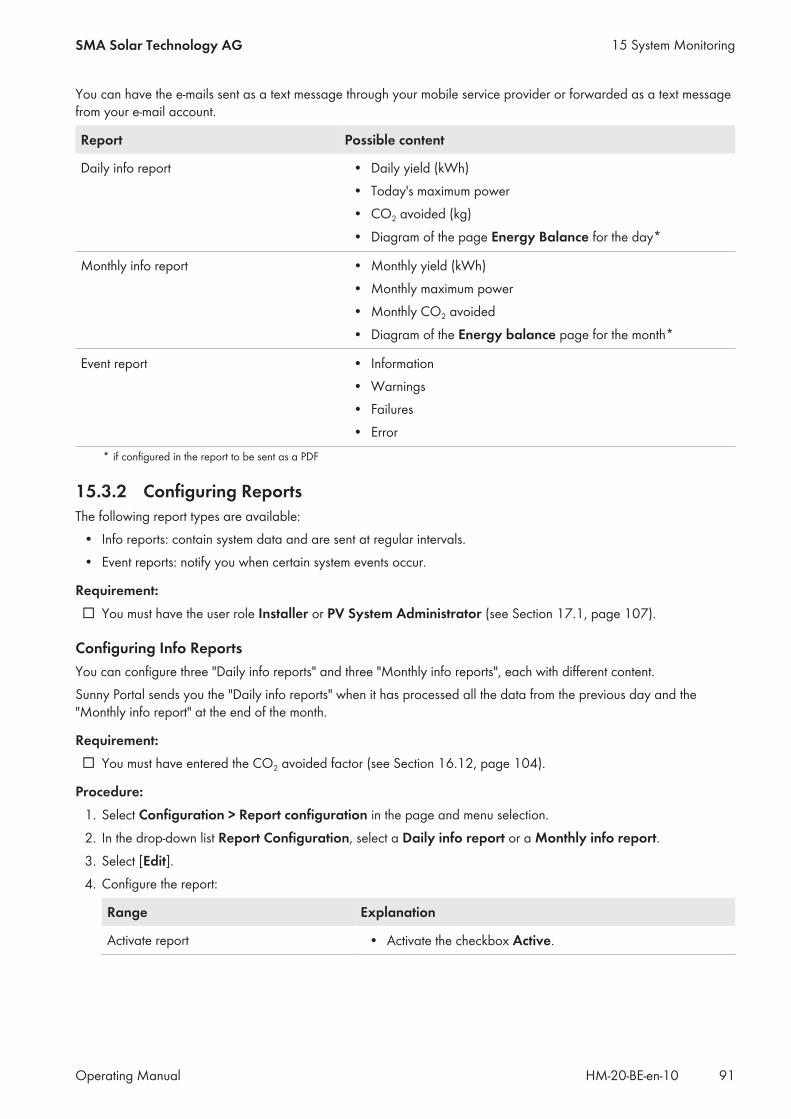
You can have the e-mails sent as a text message through your mobile service provider or forwarded as a text messagefrom your e-mail account.
Report Possible content
Daily info report • Daily yield (kWh)• Today's maximum power• CO2 avoided (kg)• Diagram of the page Energy Balance for the day*
Monthly info report • Monthly yield (kWh)• Monthly maximum power• Monthly CO2 avoided• Diagram of the Energy balance page for the month*
Event report • Information• Warnings• Failures• Error
* if configured in the report to be sent as a PDF
15.3.2 Configuring ReportsThe following report types are available:
• Info reports: contain system data and are sent at regular intervals.• Event reports: notify you when certain system events occur.
Requirement:☐ You must have the user role Installer or PV System Administrator (see Section 17.1, page 107).
Configuring Info ReportsYou can configure three "Daily info reports" and three "Monthly info reports", each with different content.Sunny Portal sends you the "Daily info reports" when it has processed all the data from the previous day and the"Monthly info report" at the end of the month.
Requirement:☐ You must have entered the CO2 avoided factor (see Section 16.12, page 104).
Procedure:1. Select Configuration > Report configuration in the page and menu selection.2. In the drop-down list Report Configuration, select a Daily info report or a Monthly info report.3. Select [Edit].4. Configure the report:
Range Explanation
Activate report • Activate the checkbox Active.
15 System MonitoringSMA Solar Technology AG
Operating Manual 91HM-20-BE-en-10

Range Explanation
Recipient • Enter the e-mail address(es) of the recipient(s) in the text fieldE-mail address(es). If you enter several e-mail addresses,separate these by commas.
Content • In the area Select channel(s), activate the content that is tobe displayed in the e-mail.
• In the area Send report as, select the format in whichSunny Portal is to send the report.If Sunny Portal is to send a Sunny Portal page along with thereport, select a page in the drop-down list in the area PortalPage to Be Sent.
• If Sunny Portal is not to send a Sunny Portal page along withthe report, select Send no page.
5. To send a test report to the stated e-mail address, select [Send test report].6. Select [Save].
Configuring Event ReportsYou can configure three event reports, each with different content.Sunny Portal sends you the event reports at the times set.
Procedure:1. Select Configuration > Report configuration in the page and menu selection.2. In the drop-down list Report configuration, select an Event report.3. Select [Edit].4. Configure the report:
Range Explanation
Activate report • Activate the checkbox Active.
Recipient • Enter the e-mail address(es) of the recipient(s) in the text fieldE-mail address(es). If you enter several e-mail addresses,separate these by commas.
15 System Monitoring SMA Solar Technology AG
Operating ManualHM-20-BE-en-1092

Range Explanation
Interval • To receive an e-mail with event report every hour, activate theoption Hourly.
• To receive one e-mail with event report per day, activate theoption Daily and, in the drop-down list, select the time youwould like to receive the e-mail.
Content You can select up to four Sunny Portal and Sunny Home Managersystem event types: Information, Warnings, Failures, Errors.
• Activate the content that is to be displayed in the e-mail.• In the area Send Report as, select the format in which
Sunny Portal is to send the report.• In the area Limit messages in one report, use the drop-
down list to select the maximum number of messages to bedisplayed in the e-mail.
• If you wish to send reports even if there are no new events,activate Send empty reports if no new events areavailable.
5. To send a test report to the stated e-mail address, select [Send test report].6. Select [Save].
15.3.3 Creating a Report for a Specific DateYou can create a report for a specific date in the past.
Requirement:☐ You must have the user role Installer or PV System Administrator (see Section 17.1, page 107).
Procedure:1. Select Configuration > Report configuration in the page and menu selection.2. Select the desired report in the drop-down list Report configuration.3. In the field Report Date in the area Regenerate Report Manually, enter the date for which you wish to create
a report. Tip: click the calendar icon and select a date in the calendar.4. Select [Generate].
☑ A message that the report has been successfully sent is displayed.
15.4 Setting Communication MonitoringIn case the Sunny Home Manager does not communicate with Sunny Portal, you can set the time which should elapsebefore Sunny Portal reports an error and notifies you by e-mail.The time which should elapse before the error is displayed by Sunny Portal and you are notified by e‑mail is defined inthe following settings:
• Alerts• Data Request Interval (see Section 12.7, page 68)
Requirement:☐ You must have the user role Installer or PV System Administrator (see Section 17.1, page 107).
15 System MonitoringSMA Solar Technology AG
Operating Manual 93HM-20-BE-en-10

Procedure:1. Select PV System Monitoring in the page and menu selection.2. In the area Communication Monitoring, select [Settings].
☑ The page Configuration communication monitoring opens.3. Click the slider and, holding the left mouse button pressed, set how quickly Sunny Portal is to report an error and
notify you by e‑mail:
Alerts Data request interval Time
Off Automatic Communication monitoring isdeactivated.
Hourly
Daily
Bounteous Automatic 3:15 h
Hourly 4:00 h
Daily 27:00 h
Tolerant Automatic 1:15 h
Hourly 2:00 h
Daily 25:00 h
Sharp Automatic 00:30 h
Hourly 1:15 h
Daily 24:15 h
4. Enter the e-mail address(es) of the recipient(s) in the text field Recipient. If you enter several e-mail addresses,separate these by commas.
5. Select [Save].
15.5 Setting the Inverter ComparisonThe inverter comparison enables Sunny Portal to recognize possible yield losses. If the specific yield of an inverterdiffers significantly from the mean yield of all the inverters, Sunny Portal can notify you by e-mail.
Requirements:☐ The PV system must contain at least two inverters.☐ You must have the user role Installer or PV System Administrator (see Section 17.1, page 107).
Procedure:1. Select PV System Monitoring in the page and menu selection.2. In the area Inverter comparison, select [Settings].
☑ The page Configuration of inverter comparison opens.3. Enter the e-mail address of the recipient in the text field Recipient. If you enter several e-mail addresses, separate
these by commas.
15 System Monitoring SMA Solar Technology AG
Operating ManualHM-20-BE-en-1094

4. PV array powerThe PV array power is preset in the text field Generator capacity [kWp]. Sunny Portal calculates the PVarray power based on the nominal power of each inverter. You can also enter the PV array power manuallyor have Sunny Portal calculate it by entering information on the strings (see Section 12.10, page 70).
5. In the text field Tolerance, enter the permissible tolerance for the inverter's specific yield. This simultaneously setsthe deviation of the inverter specific yield from which e-mail notification by Sunny Portal will be triggered.
6. To select an inverter for the inverter comparison, activate the checkbox Monitoring in the line of the inverter.7. Select [Save].
15 System MonitoringSMA Solar Technology AG
Operating Manual 95HM-20-BE-en-10

16 System Settings
16.1 Entering String PropertiesA string describes a group of series-connected PV modules. Normally, a system is made up of multiple strings. Eachstring has specific properties, such as deviation to south (azimuth) or the roof tilt angle.The yield forecast of the Sunny Home Manager plays an important role in load control. If you enter the stringproperties of your system, the Sunny Home Manager can output very precise yield forecasts.
Requirement:☐ You must have the user role Installer or PV System Administrator (see Section 17.1, page 107).
Procedure:1. Call up the inverter properties (see Section 12.2, page 66).2. Select [Edit].
☑ The menu for setting the device properties opens.3. To add a new string, select [Add string].4. To copy an existing string, select in the string line and the Copy column.5. In the column Edit of the copied string line, select .
☑ The menu for setting the string opens.6. Enter the string properties:
Input field or drop-down list Explanation
Designation Name of the string, e.g. String 1
Manufacturer PV module manufacturer
Module type Depending on the selected manufacturer, different module typesare displayed in the drop‑down list.
Module power These values are entered automatically once you have selectedthe module type. You can change the values using or the arrowkeys on the keyboard.Module surface
Efficiency
Number of modules Number of modules forming the string
Azimuth The azimuth angle indicates by how many degrees the modulesurfaces deviate from a southern orientation.
• In the text field, enter the number of degrees by which themodule surfaces deviate from a southern orientation. Enter anegative value (e.g. −20) for a deviation to the east and apositive value (e.g. 20) for a deviation to the west.
• If the module surfaces track the sun automatically, activatethe checkbox Tracking.
16 System Settings SMA Solar Technology AG
Operating ManualHM-20-BE-en-1096
Input field or drop-down list Explanation
Tilt angle The tilt angle indicates by how many degrees the module surfacesdeviate from the horizontal. In some systems, the module surfacesare optimally aligned according to the latitude. In Germany, theoptimum orientation is 30 degrees from the horizontal.
• In the text field, enter the number of degrees by which themodule surfaces deviate from the horizontal.
• If the module surfaces are optimally aligned according to thelatitude, activate the checkbox Optimized.
Description • Enter any comments.
7. Select [Accept].8. Select [Save].
16.2 Changing System DataRequirement:☐ You must have the user role Installer or PV System Administrator (see Section 17.1, page 107).
Procedure:1. Select Configuration > PV system properties in the page and menu selection.2. Select the tab PV System Data.3. Select [Edit].
☑ The menu for setting system data opens.4. Change the desired PV system data.5. Select [Save].
16.3 Changing the System NameYou can change the system name entered when you registered the Sunny Home Manager system.
Requirement:☐ You must have the user role Installer or PV System Administrator (see Section 17.1, page 107).
System name requirement:☐ The system name can have a maximum of 30 characters.
Procedure:1. Select Configuration > PV system properties in the page and menu selection.2. Select the tab PV System Data.3. Select [Edit].
☑ The menu for setting system data opens.4. Enter the desired system name in the text field Name.5. Select [Save].
16 System SettingsSMA Solar Technology AG
Operating Manual 97HM-20-BE-en-10

16.4 Setting the Nominal PV System Power
16.4.1 Manually Entering the Nominal PV System PowerThe nominal PV system power is the sum of the power of all PV modules. You can obtain the nominal PV system powerspecifications from your installer.The nominal PV system power is required in order to display the following data:
• Specific system yield• Average expected yield• Performance ratio
Nominal PV system power required for limiting active power feed-inYou must enter the nominal PV system power correctly to ensure limitation of the active power feed-in to thecorrect value (see Section 16.9, page 102). If there are changes to the installed PV system power, you will needto adjust this value.
Requirement:☐ You must have the user role Installer or PV System Administrator (see Section 17.1, page 107).
Procedure:1. Select Configuration > PV system properties in the page and menu selection.2. Select the tab PV System Data.3. Select [Edit].
☑ The menu for setting system data opens.4. In the area Power, enter the system power in the text field PV system power.5. To set the manufacturer of the PV modules, select the manufacturer in the drop-down list Manufacturer.6. To set the module types, select the module types in the drop-down list Module type.7. Select [Save].
16.4.2 Automatic Calculation of Nominal PV System PowerThe nominal PV system power is the sum of the power of all PV modules. It can be calculated automatically from thedata in the device properties.The nominal PV system power is required in order to display the following data:
• Specific system yield• Average expected yield• Performance ratio
Requirement:☐ You must have entered the PV array power of all inverters (see Section 12.10, page 70).☐ You must have the user role Installer or PV System Administrator (see Section 17.1, page 107).
Procedure:1. Select Configuration > PV system properties in the page and menu selection.2. Select the tab PV System Data.3. Select [Edit].
☑ The menu for setting system data opens.
16 System Settings SMA Solar Technology AG
Operating ManualHM-20-BE-en-1098

4. In the area Power, activate the checkbox Calculate PV system performance from device properties.☑ The calculated nominal PV system power is displayed.
5. Select [Save].
16.5 Changing the System DescriptionYou can enter important features of the system in the description. The text is displayed on the page PV systemprofile.The editor only supports text and does not support typography with HTML tags.
Requirement:☐ You must have the user role Installer or PV System Administrator (see Section 17.1, page 107).
Procedure:1. Select Configuration > PV system properties in the page and menu selection.2. Select the tab PV System Data.3. Select [Edit].
☑ The menu for setting system data opens.4. Enter a description in the area Description.5. Select [Save].
16.6 Changing Operator DataThe operator is a private individual or legal entity who owns PV systems for business purposes, for example. Theoperator can farm out use of the PV system without necessarily being the user himself.The name of the operator is displayed on the page PV system profile.
Requirement:☐ You must have the user role Installer or PV System Administrator (see Section 17.1, page 107).
Procedure:1. Select Configuration > PV system properties in the page and menu selection.2. Select the tab Operator.3. Select [Edit].
☑ The menu for setting the operator data opens.4. Enter the operator data.5. Select [Save].
16.7 Changing/Deleting the System ImageThe system image is the image in the page and menu selection next to the menu item "My Sunny Home Managersystem".
Figure 12: PV system image
16 System SettingsSMA Solar Technology AG
Operating Manual 99HM-20-BE-en-10

You can replace the standard system image with a user-defined system image. The user-defined system image will alsobe displayed at the following locations:
• On the PV system profile page• If pages have been released for Sunny Portal, the system image will be shown on the list of released systems on
the www.SunnyPortal.com homepage.You can save several images in a gallery in Sunny Portal. This makes it easy to change the system image and accessyour images from different computers.
Changing the System Image
Requirement:☐ You must have the user role Installer or PV System Administrator (see Section 17.1, page 107).
System image requirements:☐ Maximum image size: 500 kB☐ Possible image formats: JPG, PNG, GIF
Procedure:1. Select Configuration > PV system properties in the page and menu selection.2. Select the tab PV System Data.3. Select [Edit].
☑ The menu for setting system data opens.4. In the area PV system image, select [Load image].5. Select the desired image from one of your directories.6. Select [Open].7. To change the system image size, move the gray squares with the mouse.8. To move the image section, click on the image section and move it while holding the left mouse button pressed.9. Select [Save].
10. To save an image in the gallery, upload the image to the gallery as follows:• Select [Select from the gallery].• Select Upload.• Select [Browse].• Select the desired image from one of your directories.• Select [Upload selected file].• Select .
☑ The image is saved in the gallery.11. To upload an image from the gallery as the system image, select [Select from the gallery].12. Double-click the desired image.13. Select [Save].
Deleting the User-Defined System ImageIf you delete the user-defined system image, Sunny Portal will display the default system image.
Procedure:1. Select Configuration > PV system properties in the page and menu selection.2. Select the tab PV System Data.
16 System Settings SMA Solar Technology AG
Operating ManualHM-20-BE-en-10100

3. Select [Edit].☑ The menu for setting system data opens.
4. Select [No PV system image] in the area PV system image.5. Select [Save].
16.8 Entering the Feed-in Tariff, Self-Consumption Tariff and Electricity TariffThe values entered for the feed-in tariff, self-consumption tariff and electricity tariff affect the following components:
• Recommended actions in the diagram Forecast and Recommended Action on the page Current Status andForecast
• Load control via the Sunny Home Manager (either directly via the local network or via radio-controlled sockets)
Requirement:☐ You must have the user role Installer or PV System Administrator (see Section 17.1, page 107).
Procedure:1. Select Configuration > PV system properties in the page and menu selection.2. Select the tab Parameters.3. Select [Edit].
☑ The menu for parameter settings opens.4. Enter the feed-in tariff per kWh in the area Reimbursement in the text field Feed-In Tariff. Also select the
desired currency in the accompanying drop-down list.5. In the text field PV system with self-consumption, select whether self-generated PV energy is consumed in your
household (self-consumption). If you select Yes (default setting), the self-consumption of the household is taken intoconsideration in the load control and recommended actions.
6. If you receive compensation for self-consumption, enter the self-consumption tariff in the text field Self-Consumption Tariff.
7. If you do not receive compensation for self-consumption, enter 0 in the text field Self-Consumption Tariff.8. In the area Electricity Tariff , enter the time for which the electricity tariff applies in the input fields From and To.
Tip: Split the night tariff into two tariffs. Configure the first tariff up to 12 midnight. Configure the second tariff from12 midnight.
9. Enter the electricity tariff that applies to the entered time in the input field Price.10. If the electricity tariff only applies to specific weekdays, activate the checkboxes with the respective weekdays.11. If the electricity tariff applies to each weekday, activate all weekday checkboxes.12. To enter additional electricity tariffs, select and enter the data.13. Select [Save].
16 System SettingsSMA Solar Technology AG
Operating Manual 101HM-20-BE-en-10

16.9 Configuring Limitation of Active Power Feed-In
Responsibility of the system operator for limitation of active power feed-inThe system operator is responsible for the correctness of information on limiting the active power feed-in and nominalPV system power.
• Ask your grid operator beforehand whether you are permitted to use the Sunny Home Manager to limit activepower feed-in (Manufacturer's Declaration "Feed-In Management in Accordance with the Renewable EnergySources Act (EEG) 2012 with Sunny Home Manager (SHM) from SMA" available at www.SMA-Solar.com).
• Set the limitation of active power feed-in required by the grid operator. If you are not sure about this, contactyour grid operator.
• Ensure you have correct information on the nominal PV system power. If you extend the system, adjust the valuefor the nominal PV system power accordingly.
Supported inverters for the limitation of the active power feed-in to 0%Limitation of the active power feed-in to 0% is only supported by inverters that support the fallback function(fallback: in the event of a communication failure between the Sunny Home Manager and the inverter, the inverterreverts to an output power of 0 watts). For more information see the inverter manual at www.SMA-Solar.com.
Requirement:☐ With all inverters, the parameter Operating mode active power must be set to the value Active power
limitation P via system control (see Sunny Explorer user manual).☐ You must have the user role Installer or PV System Administrator (see Section 17.1, page 107).
Procedure:1. Select Configuration > PV system properties in the page and menu selection.2. Select the tab Parameters.3. Select [Edit].
☑ The menu for parameter settings opens.4. In the area Limiting of the active power feed-in, select the applicable option:
• If limitation of active power feed-in is not required for your system, select no limiting of the active powerfeed-in (default setting).
• If limitation of active power feed-in is required for your system, carry out the following steps:– To test whether the limitation of active power feed-in is working in the system, select the option max. xx
kW and enter the value 0. Thus, the Sunny Home Manager immediately limits the active power whenthe inverters start feeding into the utility grid.
– If the grid operator requires limitation to a maximum active power in kW, select the option max. xx kWand enter the maximum permitted active power in kW.
– If the grid operator requires limitation to a percentage of the nominal PV system power, select the optionMax. xx % of the nominal PV system power and enter the required percentage.
– If the grid operator requires limitation of the active power feed-in to 0%, select the option Max. xx% ofnominal PV system power and enter the value 0.
16 System Settings SMA Solar Technology AG
Operating ManualHM-20-BE-en-10102
5. Select [Save].☑ The data is being transferred. This can take up to five minutes.
6. To display the active power limitation, select Energy Balance > Current or Energy Balance > Day in the pageand menu selection.☑ In the diagrams Energy balance - Current and Energy balance - Day, the specified limitation of active
power feed-in is displayed as a red line. If the PV production exceeds the specified threshold, a blue area isshown above the red line as a maximum, and this corresponds to the current self-consumption.
16.10 Activating/Deactivating Grid Management ServicesThe Sunny Home Manager can receive the specifications for grid management services via Ethernet-basedcommunication. The grid operator can set up this link. You also have to activate grid management services for theSunny Home Manager.
Requirement:☐ You must have the user role Installer or PV System Administrator (see Section 17.1, page 107).
Procedure:1. Select Configuration > PV system properties in the page and menu selection.2. Select the tab Parameters.3. Select [Edit].
☑ The menu for parameter settings opens.4. Select the appropriate option in the area Grid management services via Ethernet based communication:
• If the Sunny Home Manager does not have to implement any grid operator specifications, select No (defaultsetting).
• If the Sunny Home Manager does have to implement grid operator specifications, select Yes and ifnecessary enter a different port in the field Port. Tip: The default setting Port 502 can normally remain set.You may have to change the port if there are several Modbus devices in the network.
5. Select [Save].
16.11 Setting the Optimization TargetThe optimization target defines the objectives you wish to achieve with your Sunny Home Manager system:
• Highest possible self-consumption (environmental aspect - ecological)• Highest possible cost savings (business aspect - economical)
The optimization target affects the following components:• Load control via the Sunny Home Manager (either directly via the local network or via radio-controlled sockets)• Recommended actions in the diagram Forecast and Recommended Action on the page Current Status and
Forecast
Requirements:☐ The feed-in tariff, self-consumption tariff and electricity tariff must be entered (see Section 16.8, page 101).☐ You must have the user role Installer or PV System Administrator (see Section 17.1, page 107).
Procedure:1. Select Configuration > PV system properties in the page and menu selection.2. Select the tab Parameters.3. Select [Edit].
☑ The menu for parameter settings opens.
16 System SettingsSMA Solar Technology AG
Operating Manual 103HM-20-BE-en-10
4. In the area Optimization Target, click the slider and, holding the left mouse button pressed, set the optimizationtarget:
• To achieve the highest self-consumption possible, move the slider towards ecological.• To achieve the greatest possible cost savings, move the slider towards economical.
5. Select [Save].
16.12 Entering the Amount of CO2 AvoidedThe CO2 factor indicates how much CO2 is produced during the power generation of one kilowatt hour. The CO2
factor can vary depending on the grid operator. To find out the level of the CO2 factor for one kilowatt hour of electriccurrent, contact your grid operator.Sunny Portal can use the CO2 factor to calculate how much CO2 was saved due to the power generation of yoursystem.You can view the value of CO2 avoided on the following pages:
• PV system profile page• Daily info report or Monthly info report (see Section 15.3.2, page 91).
Requirement:☐ You must have the user role Installer or PV System Administrator (see Section 17.1, page 107).
Procedure:1. Select Configuration > PV system properties in the page and menu selection.2. Select the tab Parameters.3. Select [Edit].
☑ The menu for parameter settings opens.4. In the area Factor, enter the CO2 factor in the text field or click the slider and, holding the left mouse button
pressed, set the CO2 factor.5. Select [Save].
16.13 Automatic Calculation of the Predicted Annual YieldSunny Portal can display in a table how the predicted annual yield of your system is likely to be distributed throughoutthe months of the year.The predicted annual yield of the system is calculated from the specific annual yield (kWh/kWp) at the system locationmultiplied by the nominal PV system power.You can obtain the specific annual yield for your system location from irradiation maps. Local conditions such as theshading or orientation of the system are not taken into account by Sunny Portal.
Requirements:☐ The nominal PV system power must be set (see Section 16.4, page 98).☐ You must have the user role Installer or PV System Administrator (see Section 17.1, page 107).
Procedure:1. Select Configuration > PV system properties in the page and menu selection.2. Select the tab Parameters.3. Select [Edit].
☑ The menu for parameter settings opens.
16 System Settings SMA Solar Technology AG
Operating ManualHM-20-BE-en-10104
4. In the area Yield Expectations , enter the specific annual yield in the text field Specific Annual Yield.☑ The predicted annual yield is displayed in the field Predicted Annual Yield.
5. To enable configuration of the average expected yield and the monthly distribution on the page AnnualComparison, activate the checkbox The monthly distribution can be configured in the diagrams.
6. Select [Save].
16.14 Setting the Monthly Distribution of the Predicted Annual YieldThe monthly distribution shows how the predicted annual yield is likely to be distributed throughout the months of theyear.You have the following options:
• Having Sunny Portal suggest the monthly distribution• Manually entering the monthly distribution
Having Sunny Portal Suggest the Monthly Distribution
Requirements:☐ The system location must be entered (see Section 16.2, page 97).☐ You must have the user role Installer or PV System Administrator (see Section 17.1, page 107).
Procedure:1. Select Configuration > PV system properties in the page and menu selection.2. Select the tab Parameters.3. Select [Edit].
☑ The menu for parameter settings opens.4. In the area Yield expectations, select [Suggest a Monthly Distribution].
☑ The monthly distribution is displayed in the table with the months.5. To display the average expected yield and the monthly distribution in the diagrams on the pages Annual
Comparison and Energy and Power, activate the checkbox Display the monthly distribution in the yearlycomparison, as well as energy and power.
6. To enable configuration of the average expected yield on the pages Annual Comparison and Energy andPower, activate the checkbox The monthly distribution can be configured in the diagrams.
7. Select [Save].
Manually Entering the Monthly Distribution1. Select Configuration > PV system properties in the page and menu selection.2. Select the tab Parameters.3. Select [Edit].
☑ The menu for parameter settings opens.4. In the area Yield Expectations, enter the values in the text fields in % in the table with the months.5. To display the predicted annual yield and the monthly distribution in the diagrams on the pages Annual
Comparison and Energy and Power, activate the checkbox Display the monthly distribution in the yearlycomparison, as well as energy and power.
6. To enable configuration of the predicted annual yield on the pages Annual Comparison and Energy andPower, activate the checkbox The monthly distribution can be configured in the diagrams.
7. Select [Save].
16 System SettingsSMA Solar Technology AG
Operating Manual 105HM-20-BE-en-10

16.15 Editing Data ReleasesYou can set whether to make your PV system data available to the PV database "www.sonnenertrag.eu" or the Internetportal Sunny Places."sonnenertrag.eu" is an online platform where you can publish the yields of your PV system and compare them withother registered PV systems.Sunny Places is an Internet portal for private PV system owners where you can publicly present your PV system inaddition to Sunny Portal, compare your PV system with other registered PV systems, and exchange experiences withother PV system owners. Sunny Places is free of charge.
Procedure:1. Select Configuration > PV system properties in the page and menu selection.2. Select the tab Data releases.3. Select [Edit].
☑ The menu for setting data releases opens.4. Activate or deactivate the data releases checkbox.5. Select [Save].
16 System Settings SMA Solar Technology AG
Operating ManualHM-20-BE-en-10106

17 User Management
17.1 User Groups and User RightsIf you have the user role PV system administrator, you can create further users in Sunny Portal so that they haveaccess to your Sunny Portal system. You can assign various roles to users. The roles are differentiated by the rights theygrant to users in your Sunny Portal system. The following roles are possible:
• Guest• Standard user• Installer• System administrator
Rights Role
Guest Standard user Installer PV systemadministrator
Log in ✓ ✓ ✓ ✓
View pages ✓ ✓ ✓ ✓
Change and delete pages − − ✓ ✓
Release pages for viewing inSunny Portal and publish pages
− − ✓ ✓
View live data − ✓ ✓ ✓
Save diagram data − ✓ ✓ ✓
View and change user informa-tion
✓ ✓ ✓ ✓
Changing the Sunny Portal Pass-word
− ✓ ✓ ✓
Changing the System Password − − ✓ ✓
View device properties − ✓ ✓ ✓
Change device properties − − ✓ ✓
View system properties − ✓ ✓ ✓
Change system properties − − ✓ ✓
View report configuration − ✓ ✓ ✓
Change report configuration − − ✓ ✓
Configure radio-controlled sock-ets
− ✓ ✓ ✓
Set the operating mode of ra-dio-controlled sockets viaSunny Portal
− ✓ ✓ ✓
Replace Sunny Home Manager − − − ✓
17 User ManagementSMA Solar Technology AG
Operating Manual 107HM-20-BE-en-10
Rights Role
Guest Standard user Installer PV systemadministrator
Delete Sunny Home Manager − − ✓ ✓
Reassign the Sunny Home Man-ager to the system
− − ✓ ✓
Delete the Sunny Home Man-ager system
− − ✓ ✓
Add devices − − ✓ ✓
Replace devices − − ✓ ✓
Delete devices − − ✓ ✓
Set communication monitoring − − ✓ ✓
Set inverter comparison − − ✓ ✓
View the PV system logbook − ✓ ✓ ✓
Confirm entries in the PV systemlogbook
− − ✓ ✓
Import data − − ✓ ✓
Read off the software packageversion
− ✓ ✓ ✓
View user management − − − ✓
Create and delete users and as-sign roles
− − − ✓
17.2 Creating a New UserRequirement:☐ You must be a system administrator (see Section 17.1, page 107).
Procedure:1. Select Configuration > User management in the page and menu selection.2. Select [New User].3. Enter the e-mail address of the new user in the text field E-mail address.4. Activate the desired role option in the area Roles.5. Select [Save].☑ The new user receives an e-mail with the access data.
17.3 Deleting a UserRequirement:☐ You must be a system administrator (see Section 17.1, page 107).
17 User Management SMA Solar Technology AG
Operating ManualHM-20-BE-en-10108

Procedure:1. Select Configuration > User management in the page and menu selection.2. In the user line and the column Delete, select .3. Confirm the security prompt with [Yes].
17.4 Changing User RightsRequirement:☐ You must be a system administrator (see Section 17.1, page 107).
Procedure:1. Select Configuration > User management in the page and menu selection.2. In the user line and the column Edit, select .
☑ The areas E‑mail Address and Roles open.3. Activate the desired role option in the area Roles.4. Select [Save].☑ The user rights are changed for the Sunny Home Manager system.
17.5 Changing User InformationEvery user can enter user information. User information includes, for example, the user's name and address.
Procedure:1. Select User Info/Logout > User information in the page and menu selection.2. Select [Edit].
☑ The menu for setting user information opens.3. Enter the user information.4. Select [Save].
17 User ManagementSMA Solar Technology AG
Operating Manual 109HM-20-BE-en-10

18 Password Information
18.1 Requirements for a Secure System PasswordYou increase the security of your password with the following measures:
• Select passwords containing at least eight characters.• Use combinations of upper-case and lower-case letters, special characters and numbers.• Do not use names or common words (e.g. "dog", "cat", "house").• For the password, avoid using words that have any personal relevance to you such as the names of persons or
pets, personnel numbers, identification numbers or car license plates.• Do not repeat names or words (e.g. "househouse" or "catcat").• Do not use combinations of numbers or letters in the same order as they appear on your keyboard (e.g. "12345",
"qwert").
18.2 Required Passwords
Sunny Portal PasswordYou can log into Sunny Portal with the Sunny Portal password.If you register a PV system in Sunny Portal, you must specify a Sunny Portal password during registration.If you have registered as a new user in Sunny Portal (see Section 17.2, page 108), you will receive an e‑mail with aSunny Portal password.You can change the Sunny Portal password (see Section 18.3, page 110).
System PasswordAll devices connected via Speedwire with the same password form a system. For this reason, a password used for alldevices in a system is called a system password.You can only access the devices in your PV system via your communication product (e.g. Sunny Explorer,Sunny Home Manager) if all devices have the same password.You must define the system password in Sunny Portal when you register the Sunny Home Manager system. The systempassword that you defined upon registration of the Sunny Home Manager is the password of the user group Installer.You can change the system password (see Section 18.3, page 110).
Password for Edimax smart plug switches SP-2101WAll Edimax smart plug switches in the system must have the same password. If there are different passwords for thesmart plug switches, the Sunny Home Manager cannot control all smart plug switches.Make sure that the shared password is entered at the following positions:
• In the separate Edimax app for each smart plug switch registered there.• In the Sunny Home Manager properties (see Section 12.2 "Calling Up the Properties of a Device", page 66)
18.3 Changing Passwords
Changing the Sunny Portal Password
Requirement:☐ You must be a Standard user, Installer or PV system administrator (see Section 17.1, page 107).
Sunny Portal password requirements:☐ The Sunny Portal password should consist of at least eight characters.
18 Password Information SMA Solar Technology AG
Operating ManualHM-20-BE-en-10110
The following special characters are permitted:• ! $ % & / ( ) = ? + − . ; : _ < > #• Space
Procedure:1. Select User Info/Logout > Personal data in the page and menu selection.2. On the tab Personal data, select the hyperlink If you want to change your password, please click here.3. Enter the old and the new Sunny Portal passwords in the designated text fields.4. Select [Save].
Changing the System Password
Requirements:☐ You must have the user role Installer or PV System Administrator (see Section 17.1, page 107).
System password requirements:☐ The system password can be a maximum of twelve characters.
The following special characters are permitted:• ? _ ! -
Procedure:1. Call up the device properties of the Sunny Home Manager (see Section 12.2, page 66).2. Select [Edit].
☑ The menu for setting the device properties opens.3. Enter a new password in the PV system password field.4. Enter the new password again in the field Repeat password.5. Select [Save].☑ The Sunny Home Manager changes the password for all devices.
18.4 Procedure in Case of Forgotten Passwords
Forgotten Sunny Portal Password1. Go to www.SunnyPortal.com.2. In the Login area, select the Forgotten password link.3. Enter your e-mail address in the E-mail field.4. Select [Generate New Password].
☑ You will receive an e-mail with a new password.5. Change the assigned password (see Section 18.3, page 110).
Forgotten System Password• Activate each device with a personal unlocking key (PUK) (see the Sunny Explorer help).
Forgotten password for Edimax WLAN radio-controlled sockets SP-2101WSee manufacturer's manual.
18 Password InformationSMA Solar Technology AG
Operating Manual 111HM-20-BE-en-10
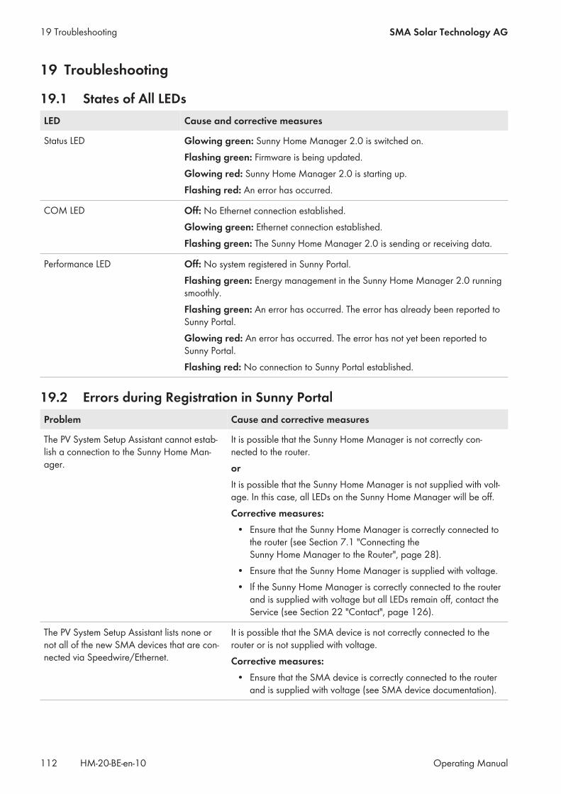
19 Troubleshooting
19.1 States of All LEDsLED Cause and corrective measures
Status LED Glowing green: Sunny Home Manager 2.0 is switched on.Flashing green: Firmware is being updated.Glowing red: Sunny Home Manager 2.0 is starting up.Flashing red: An error has occurred.
COM LED Off: No Ethernet connection established.Glowing green: Ethernet connection established.Flashing green: The Sunny Home Manager 2.0 is sending or receiving data.
Performance LED Off: No system registered in Sunny Portal.Flashing green: Energy management in the Sunny Home Manager 2.0 runningsmoothly.Flashing green: An error has occurred. The error has already been reported toSunny Portal.Glowing red: An error has occurred. The error has not yet been reported toSunny Portal.Flashing red: No connection to Sunny Portal established.
19.2 Errors during Registration in Sunny PortalProblem Cause and corrective measures
The PV System Setup Assistant cannot estab-lish a connection to the Sunny Home Man-ager.
It is possible that the Sunny Home Manager is not correctly con-nected to the router.orIt is possible that the Sunny Home Manager is not supplied with volt-age. In this case, all LEDs on the Sunny Home Manager will be off.Corrective measures:
• Ensure that the Sunny Home Manager is correctly connected tothe router (see Section 7.1 "Connecting theSunny Home Manager to the Router", page 28).
• Ensure that the Sunny Home Manager is supplied with voltage.• If the Sunny Home Manager is correctly connected to the router
and is supplied with voltage but all LEDs remain off, contact theService (see Section 22 "Contact", page 126).
The PV System Setup Assistant lists none ornot all of the new SMA devices that are con-nected via Speedwire/Ethernet.
It is possible that the SMA device is not correctly connected to therouter or is not supplied with voltage.Corrective measures:
• Ensure that the SMA device is correctly connected to the routerand is supplied with voltage (see SMA device documentation).
19 Troubleshooting SMA Solar Technology AG
Operating ManualHM-20-BE-en-10112
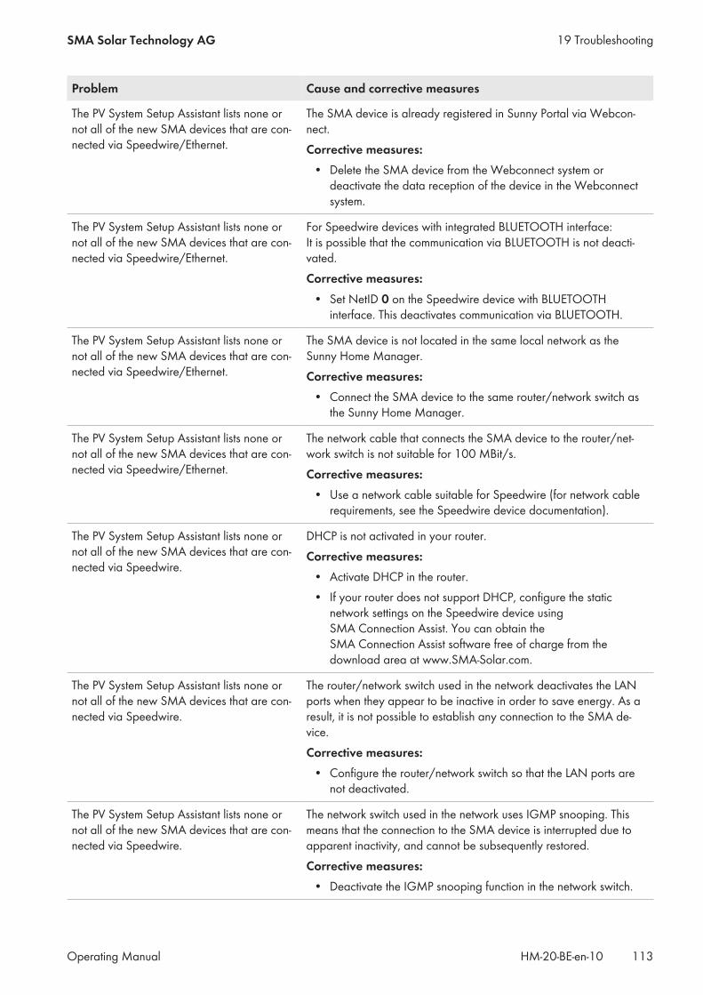
Problem Cause and corrective measures
The PV System Setup Assistant lists none ornot all of the new SMA devices that are con-nected via Speedwire/Ethernet.
The SMA device is already registered in Sunny Portal via Webcon-nect.Corrective measures:
• Delete the SMA device from the Webconnect system ordeactivate the data reception of the device in the Webconnectsystem.
The PV System Setup Assistant lists none ornot all of the new SMA devices that are con-nected via Speedwire/Ethernet.
For Speedwire devices with integrated BLUETOOTH interface: It is possible that the communication via BLUETOOTH is not deacti-vated.Corrective measures:
• Set NetID 0 on the Speedwire device with BLUETOOTHinterface. This deactivates communication via BLUETOOTH.
The PV System Setup Assistant lists none ornot all of the new SMA devices that are con-nected via Speedwire/Ethernet.
The SMA device is not located in the same local network as theSunny Home Manager.Corrective measures:
• Connect the SMA device to the same router/network switch asthe Sunny Home Manager.
The PV System Setup Assistant lists none ornot all of the new SMA devices that are con-nected via Speedwire/Ethernet.
The network cable that connects the SMA device to the router/net-work switch is not suitable for 100 MBit/s.Corrective measures:
• Use a network cable suitable for Speedwire (for network cablerequirements, see the Speedwire device documentation).
The PV System Setup Assistant lists none ornot all of the new SMA devices that are con-nected via Speedwire.
DHCP is not activated in your router.Corrective measures:
• Activate DHCP in the router.• If your router does not support DHCP, configure the static
network settings on the Speedwire device usingSMA Connection Assist. You can obtain theSMA Connection Assist software free of charge from thedownload area at www.SMA-Solar.com.
The PV System Setup Assistant lists none ornot all of the new SMA devices that are con-nected via Speedwire.
The router/network switch used in the network deactivates the LANports when they appear to be inactive in order to save energy. As aresult, it is not possible to establish any connection to the SMA de-vice.Corrective measures:
• Configure the router/network switch so that the LAN ports arenot deactivated.
The PV System Setup Assistant lists none ornot all of the new SMA devices that are con-nected via Speedwire.
The network switch used in the network uses IGMP snooping. Thismeans that the connection to the SMA device is interrupted due toapparent inactivity, and cannot be subsequently restored.Corrective measures:
• Deactivate the IGMP snooping function in the network switch.
19 TroubleshootingSMA Solar Technology AG
Operating Manual 113HM-20-BE-en-10

Problem Cause and corrective measures
The PV System Setup Assistant lists none ornot all of the new SMA devices that are con-nected via Speedwire.
The firewall may not have been set up correctly.Corrective measures:
• Enable ports 9523 and 3478 in the firewall (see firewalldocumentation).
The PV System Setup Assistant lists none ornot all of the new SMA devices that are con-nected via Speedwire.
The firewall or IP filter may not have been configured correctly.Corrective measures:
• Adjust the firewall or IP filter settings (see firewall- or routerdocumentation).
The PV System Setup Assistant cannot find aSunny Home Manager with the serial numberand registration ID entered.
The serial number and/or the registration ID may have been enteredincorrectly.Corrective measures:
• Ensure that the entries are correct.
The PV System Setup Assistant cannot find aSunny Home Manager with the serial numberand registration ID entered.
It is possible that the registration procedure was previously initiatedbut not completed.Corrective measures:
• Perform a complete reset of the Sunny Home Manager (seeSection 19.5, page 116).
The PV System Setup Assistant cannot find aSunny Home Manager with the serial numberand registration ID entered.
It is possible that the Sunny Home Manager is not correctly con-nected to the router.Corrective measures:
• Ensure that the Sunny Home Manager is correctly connected tothe router (see Section 7.1 "Connecting theSunny Home Manager to the Router", page 28).
The PV System Setup Assistant cannot find aSunny Home Manager with the serial numberand registration ID entered.
DHCP is possibly not activated on your router or there is a proxyserver in your network. For this reason, Sunny Home Manager can-not establish a connection to Sunny Portal.Corrective measures:
• Establish the connection to Sunny Portal using theSunny Home Manager Assistant (see Section 19.3 "Using theSunny Home Manager Assistant", page 115).
The PV System Setup Assistant cannot find aSunny Home Manager with the serial numberand registration ID entered.
The Sunny Home Manager has already been assigned to a system inSunny Portal with your e-mail address.Corrective measures:
• Delete the Sunny Home Manager from the PV system (seeSection 14 "System Management", page 84).or
• Register the Sunny Home Manager with the PV System SetupAssistant again (see Section 14.4 "Reassigning theSunny Home Manager to the Sunny Portal System after theReset", page 86).
19 Troubleshooting SMA Solar Technology AG
Operating ManualHM-20-BE-en-10114
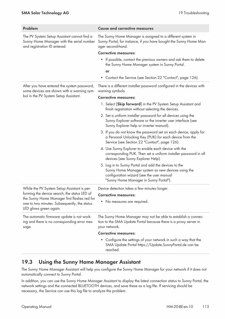
Problem Cause and corrective measures
The PV System Setup Assistant cannot find aSunny Home Manager with the serial numberand registration ID entered.
The Sunny Home Manager is assigned to a different system inSunny Portal, for instance, if you have bought the Sunny Home Man-ager second-hand.Corrective measures:
• If possible, contact the previous owners and ask them to deletethe Sunny Home Manager system in Sunny Portal.or
• Contact the Service (see Section 22 "Contact", page 126).
After you have entered the system password,some devices are shown with a warning sym-bol in the PV System Setup Assistant.
There is a different installer password configured in the devices withwarning symbols.Corrective measures:
1. Select [Skip forward] in the PV System Setup Assistant andfinish registration without selecting the devices.
2. Set a uniform installer password for all devices using theSunny Explorer software or the inverter user interface (seeSunny Explorer help or inverter manual).
3. If you do not know the password set on each device, apply fora Personal Unlocking Key (PUK) for each device from theService (see Section 22 "Contact", page 126).
4. Use Sunny Explorer to enable each device with thecorresponding PUK. Then set a uniform installer password in alldevices (see Sunny Explorer Help).
5. Log in to Sunny Portal and add the devices to theSunny Home Manager system as new devices using theconfiguration wizard (see the user manual"Sunny Home Manager in Sunny Portal").
While the PV System Setup Assistant is per-forming the device search, the status LED ofthe Sunny Home Manager first flashes red forone to two minutes. Subsequently, the statusLED glows green again.
Device detection takes a few minutes longer.Corrective measures:
• No measures are required.
The automatic firmware update is not work-ing and there is no corresponding error mes-sage.
The Sunny Home Manager may not be able to establish a connec-tion to the SMA Update Portal because there is a proxy server inyour network.Corrective measures:
• Configure the settings of your network in such a way that theSMA Update Portal https://Update.SunnyPortal.de can bereached.
19.3 Using the Sunny Home Manager AssistantThe Sunny Home Manager Assistant will help you configure the Sunny Home Manager for your network if it does notautomatically connect to Sunny Portal.In addition, you can use the Sunny Home Manager Assistant to display the latest connection status to Sunny Portal, thenetwork settings and the connected BLUETOOTH devices, and save these as a log file. If servicing should benecessary, the Service can use this log file to analyze the problem.
19 TroubleshootingSMA Solar Technology AG
Operating Manual 115HM-20-BE-en-10

Procedure:1. Use a network cable to connect the computer to the router to which the Sunny Home Manager is connected.2. In the download area at www.SMA-Solar.com, download the Sunny Home Manager Assistant for the operating
system of your computer.3. Start the Sunny Home Manager Assistant by double-clicking on the file name.4. Follow the instructions given in the Sunny Home Manager Assistant.
19.4 Error in the Sunny Home Manager AssistantProblem Cause and corrective measure
The Sunny Home Manager Assis-tant does not detect aSunny Home Manager.
The computer with the Sunny Home Manager Assistant is not connected to therouter to which the Sunny Home Manager is connected.Corrective measures:
• Connect the computer with the Sunny Home Manager Assistant to the routerto which the Sunny Home Manager is connected.
19.5 Resetting the Sunny Home ManagerLoss of data due to replacement or due to resetting to default settingsIf the Sunny Home Manager is reset to the default settings or replaced, all data saved in theSunny Home Manager will be deleted. The data saved in Sunny Portal can be transmitted to theSunny Home Manager after calling up the PV system again in Sunny Portal. Devices that were connected to theSunny Home Manager via EEBus must be reconnected (see technical information "SMA SMART HOME - Homeappliance energy management using EEBus").
Default settings• To reset the Sunny Home Manager to the default settings, press down and hold the reset button using a sharp
object for two to six seconds.☑ LEDs flash first green and then red.
Restart• To restart the Sunny Home Manager, press down and hold the reset button using a sharp object for longer than
six seconds.☑ LEDs go out. The status LED then glows red constantly during system startup.
Pressing down and holding the reset button for less than two seconds has no effect.
19.6 Incomplete/Outdated/Faulty Data on the User InterfaceProblem Cause and corrective measures
The page Energy Balance is not displayed. The Energy balance page is only displayed if the integrated mea-suring device or a separate SMA Energy Meter supplies measure-ment data from the grid-connection point.Corrective measures:
• Ensure that a measuring device is installed at the grid-connectionpoint. Assign the measuring device (integrated or separateSMA Energy Meter) to the grid-connection point in theSunny Home Manager properties.
19 Troubleshooting SMA Solar Technology AG
Operating ManualHM-20-BE-en-10116
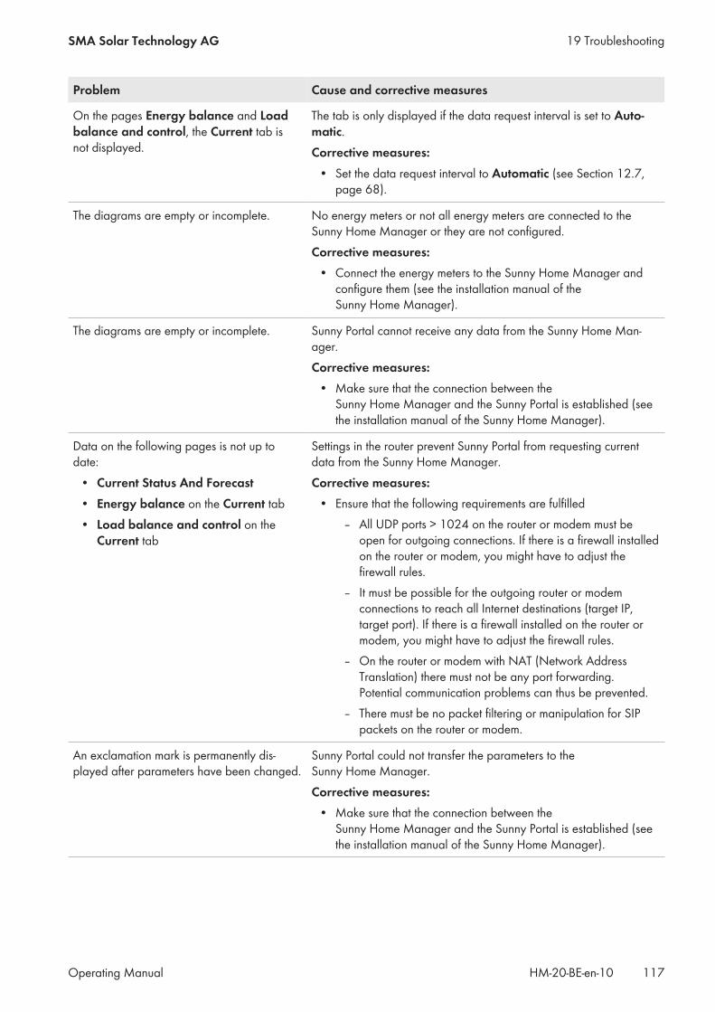
Problem Cause and corrective measures
On the pages Energy balance and Loadbalance and control, the Current tab isnot displayed.
The tab is only displayed if the data request interval is set to Auto-matic.Corrective measures:
• Set the data request interval to Automatic (see Section 12.7,page 68).
The diagrams are empty or incomplete. No energy meters or not all energy meters are connected to theSunny Home Manager or they are not configured.Corrective measures:
• Connect the energy meters to the Sunny Home Manager andconfigure them (see the installation manual of theSunny Home Manager).
The diagrams are empty or incomplete. Sunny Portal cannot receive any data from the Sunny Home Man-ager.Corrective measures:
• Make sure that the connection between theSunny Home Manager and the Sunny Portal is established (seethe installation manual of the Sunny Home Manager).
Data on the following pages is not up todate:
• Current Status And Forecast• Energy balance on the Current tab• Load balance and control on the
Current tab
Settings in the router prevent Sunny Portal from requesting currentdata from the Sunny Home Manager.Corrective measures:
• Ensure that the following requirements are fulfilled– All UDP ports > 1024 on the router or modem must be
open for outgoing connections. If there is a firewall installedon the router or modem, you might have to adjust thefirewall rules.
– It must be possible for the outgoing router or modemconnections to reach all Internet destinations (target IP,target port). If there is a firewall installed on the router ormodem, you might have to adjust the firewall rules.
– On the router or modem with NAT (Network AddressTranslation) there must not be any port forwarding.Potential communication problems can thus be prevented.
– There must be no packet filtering or manipulation for SIPpackets on the router or modem.
An exclamation mark is permanently dis-played after parameters have been changed.
Sunny Portal could not transfer the parameters to theSunny Home Manager.Corrective measures:
• Make sure that the connection between theSunny Home Manager and the Sunny Portal is established (seethe installation manual of the Sunny Home Manager).
19 TroubleshootingSMA Solar Technology AG
Operating Manual 117HM-20-BE-en-10

Problem Cause and corrective measures
Sunny Portal is displaying unrealistic data. The integrated measuring device of the Sunny Home Manager or theseparate SMA Energy Meter is not correctly connected or config-ured.Corrective measures:
• Ensure that all devices are correctly connected and configured.
Sunny Portal is not showing any weatherforecast in the diagram Forecast and rec-ommended action.
It can take up to 24 hours after the Sunny Home Manager has beeninitially registered in Sunny Portal until the weather forecast is dis-played.Corrective measures:
• After 24 hours, check again to see whether the weather forecastis displayed.
• If after 24 hours there is still no weather forecast displayed,contact the Service team (see Section 22, page 126).
The animated graphic on the page Currentstatus and Forecast is not displaying anycurrent data.
The reception of current data from the Sunny Home Manager is onlypossible if the data request interval is set to Automatic.Corrective measures:
• Set the data request interval to Automatic (see Section 12.7,page 68).
The animated graphic on the page Currentstatus and Forecast is not displaying anycurrent data.
It is possible that no PV production meter is connected to theSunny Home Manager and that too many data capture devices (e.g.several computers with Sunny Explorer) are simultaneously accessingthe devices of your PV system.Corrective measures:
• Ensure that, apart from the Sunny Home Manager, a maximumof two other data capture devices are accessing your system atany one time.
No data is displayed on the Current tab onthe page Load Balance and Control.
Too many data capture devices (e.g. several computers withSunny Explorer) may be simultaneously accessing the devices of yoursystem.Corrective measures:
• Ensure that, apart from the Sunny Home Manager, a maximumof two other data capture devices are accessing your system atany one time.
19 Troubleshooting SMA Solar Technology AG
Operating ManualHM-20-BE-en-10118
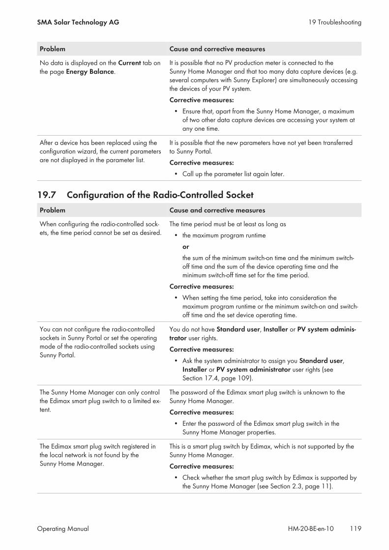
Problem Cause and corrective measures
No data is displayed on the Current tab onthe page Energy Balance.
It is possible that no PV production meter is connected to theSunny Home Manager and that too many data capture devices (e.g.several computers with Sunny Explorer) are simultaneously accessingthe devices of your PV system.Corrective measures:
• Ensure that, apart from the Sunny Home Manager, a maximumof two other data capture devices are accessing your system atany one time.
After a device has been replaced using theconfiguration wizard, the current parametersare not displayed in the parameter list.
It is possible that the new parameters have not yet been transferredto Sunny Portal.Corrective measures:
• Call up the parameter list again later.
19.7 Configuration of the Radio-Controlled SocketProblem Cause and corrective measures
When configuring the radio-controlled sock-ets, the time period cannot be set as desired.
The time period must be at least as long as• the maximum program runtime
orthe sum of the minimum switch-on time and the minimum switch-off time and the sum of the device operating time and theminimum switch-off time set for the time period.
Corrective measures:• When setting the time period, take into consideration the
maximum program runtime or the minimum switch-on and switch-off time and the set device operating time.
You can not configure the radio-controlledsockets in Sunny Portal or set the operatingmode of the radio-controlled sockets usingSunny Portal.
You do not have Standard user, Installer or PV system adminis-trator user rights.Corrective measures:
• Ask the system administrator to assign you Standard user,Installer or PV system administrator user rights (seeSection 17.4, page 109).
The Sunny Home Manager can only controlthe Edimax smart plug switch to a limited ex-tent.
The password of the Edimax smart plug switch is unknown to theSunny Home Manager.Corrective measures:
• Enter the password of the Edimax smart plug switch in theSunny Home Manager properties.
The Edimax smart plug switch registered inthe local network is not found by theSunny Home Manager.
This is a smart plug switch by Edimax, which is not supported by theSunny Home Manager.Corrective measures:
• Check whether the smart plug switch by Edimax is supported bythe Sunny Home Manager (see Section 2.3, page 11).
19 TroubleshootingSMA Solar Technology AG
Operating Manual 119HM-20-BE-en-10
19.8 Messages concerning Active Power Limitation in the System LogbookProblem Cause and corrective measures
Message in the system logbook: Supplied power has exceeded the per-mitted value several times.
Although the function Limitation of active power feed-in is acti-vated, more than the maximum permitted active power has been fedinto the utility grid.Corrective measures:
• Ensure that the feed-in meter is configured correctly (seeSection 12.6, page 67).
• Ensure that the parameter Operating mode active power isset to the value Active power limitation P via system controlfor all inverters.
Message in the system logbook: Act. power limitation deactivated due toincorr. configuration.
The function Limiting of the active power feed-in was deactivatedby Sunny Home Manager because the system configuration inSunny Portal was faulty.Corrective measures:
• This message can appear while making changes to theSunny Home Manager system, e.g. upon device replacement. Inthis case, no action is needed.
• If the message appears over an extended time period, contactthe Service (see Section 22, page 126).
Message in the system logbook: Disturbance: act. power limitation activated w/o re-gard to own consumption
The function Limiting of the active power feed-in is faulty becausethere is no data from the feed-in meter. Risk of yield loss because theself-consumption of the household cannot be taken into account.Corrective measures:
• Ensure that the feed-in meter is working and correctly connected.
Message in the system logbook: Inverter does not respond to activepower limitation
At least one inverter is not responding to limit the active power feed-in.In this case, the Sunny Home Manager initiates stronger activepower limitation in the remaining inverters. Consequently, the maxi-mum permitted active power feed-in is complied with.If the message Fed-in power has repeatedly exceeded the per-mitted value appears on the same day, an error is present.Corrective measures:
• Ensure that the parameter Operating mode active power isset to the value Active power limitation P via system controlfor all inverters.
19.9 Devices with Communication via Data Exchange ProtocolProblem Cause and corrective measures
Message in the system logbook:EM gateway not found:SEMP, name:
The gateway is not connected to the local network.Corrective measures:
• Check whether all network cable plugs are inserted and locked.
19 Troubleshooting SMA Solar Technology AG
Operating ManualHM-20-BE-en-10120

Problem Cause and corrective measures
Message in the system logbook:EM gateway not found:SEMP, name:
The voltage supply of the gateway is faulty.Corrective measures:
• Check whether the power plug of the gateway is plugged into the outlet.
Message in the system logbook:EM gateway not found:SEMP, name:
The gateway could not be found by the Sunny Home Manager.Corrective measures:
• Restart the gateway (see manual of the gateway).
Message in the system logbook:EM gateway not found:SEMP, name:
The Sunny Home Manager and the gateway are located in different local net-works.Corrective measures:
• Connect the gateway and the Sunny Home Manager to the same networkswitch/router.
Message in the system logbook:EM gateway not found:SEMP, name:
The Sunny Home Manager and the gateway are configured for different IP sub-nets.Corrective measures:
• If your router supports DHCP, configure the Sunny Home Manager (defaultsetting) and the gateway to DHCP (see manual of the gateway).
• If your router does not support DHCP, manually assign IP addresses in thesame subnet for the Sunny Home Manager and the gateway (see manual ofthe respective device).
Message in the system logbook:EM gateway not found:SEMP, name:
The voltage supply of the device is faulty.Corrective measures:
• Check whether the power plug of the device is plugged into the outlet.
Message in the system logbook:EM gateway not found:SEMP, name:
The device is not connected to its gateway.Corrective measures:
• Check whether the communication between the device and the gateway isworking. The device might be outside the range of its gateway (e.g. withpower-line communication).
Message in the system logbook:EM gateway not found:SEMP, name:
The device could not be found by the Sunny Home Manager.Corrective measures:
• Restart the device (see manual of the device).
Message in the system logbook:EM gateway not found:SEMP, name:
One or more devices are not correctly configured in the gateway or for the smartgrid.Corrective measures:
• Configure the device for its gateway (see manual of the gateway).• Configure the device for the smart grid (see manual of the respective
device).
Message in the system logbook:Communication with the EMgateway disturbed: SEMP,name:
The gateway is not connected to the local network.Corrective measures:
• Check whether all network cable plugs are inserted and locked.
19 TroubleshootingSMA Solar Technology AG
Operating Manual 121HM-20-BE-en-10

Problem Cause and corrective measures
Message in the system logbook:Communication with the EMgateway disturbed: SEMP,name:
The gateway is not communicating correctly with the Sunny Home Manager.Corrective measures:
• Restart the gateway (see manual of the gateway).
Message in the system logbook:Communication with the EMgateway disturbed: SEMP,name:
The device is not communicating correctly with its gateway.Corrective measures:
• Check whether the communication between the device and the gateway isworking. The device might be outside the range of its gateway (e.g. withpower-line communication).
• Restart the gateway (see manual of the gateway).• Restart the device (see manual of the device).
Message in the system logbook:EM gateway has incompati-ble firmware: SEMP, name:
The supported firmware version is not installed on the gateway or on theSunny Home Manager.Corrective measures:
• Update the gateway to the supported firmware version (see manual of thegateway).
• Update to firmware version 1.10.0.R or higher for theSunny Home Manager. Ensure that the automatic software update of theSunny Home Manager is activated (see Section 12.8, page 69).
Message in the system logbook:EM gateway has incompati-ble firmware: SEMP, name:
The supported firmware version is not installed on the device or on theSunny Home Manager.Corrective measures:
• Update the gateway to the supported firmware version (see the devicemanual).
• Update to firmware version 1.10.0.R or higher for theSunny Home Manager. Ensure that the automatic software update of theSunny Home Manager is activated (see Section 12.8, page 69).
Message in the system logbook:EM communication: An internal error has oc-curred (error number: XXXX*)
A software error has occurred on the Sunny Home Manager.Corrective measures:
• Reset the Sunny Home Manager (see Section 19.5, page 116)
* "XXXX" is a placeholder for the respective four-digit error number.
19 Troubleshooting SMA Solar Technology AG
Operating ManualHM-20-BE-en-10122
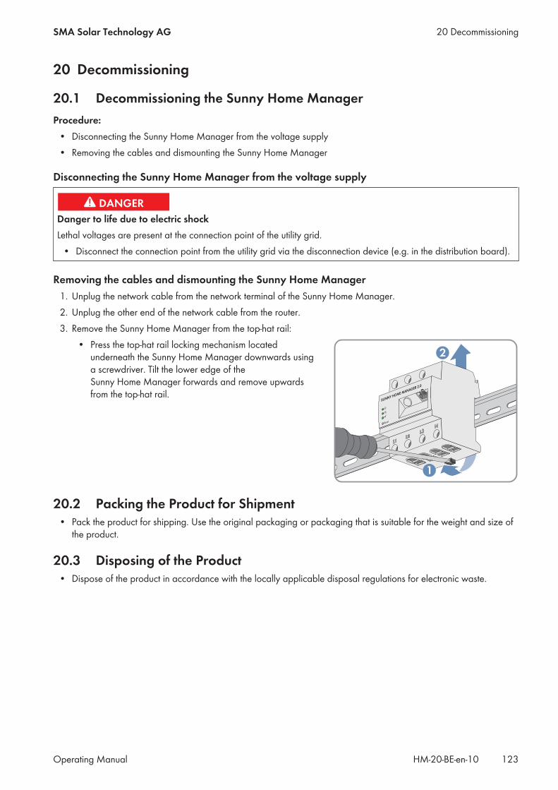
20 Decommissioning
20.1 Decommissioning the Sunny Home ManagerProcedure:
• Disconnecting the Sunny Home Manager from the voltage supply• Removing the cables and dismounting the Sunny Home Manager
Disconnecting the Sunny Home Manager from the voltage supply
Danger to life due to electric shockLethal voltages are present at the connection point of the utility grid.
• Disconnect the connection point from the utility grid via the disconnection device (e.g. in the distribution board).
Removing the cables and dismounting the Sunny Home Manager1. Unplug the network cable from the network terminal of the Sunny Home Manager.2. Unplug the other end of the network cable from the router.3. Remove the Sunny Home Manager from the top-hat rail:
• Press the top-hat rail locking mechanism locatedunderneath the Sunny Home Manager downwards usinga screwdriver. Tilt the lower edge of theSunny Home Manager forwards and remove upwardsfrom the top-hat rail.
Reset
SUNNY HOME MANAGER 2.0
2
1
20.2 Packing the Product for Shipment• Pack the product for shipping. Use the original packaging or packaging that is suitable for the weight and size of
the product.
20.3 Disposing of the Product• Dispose of the product in accordance with the locally applicable disposal regulations for electronic waste.
20 DecommissioningSMA Solar Technology AG
Operating Manual 123HM-20-BE-en-10

21 Technical Data
Energy manager
Connection to the local router via Ethernet cable (10/100 Mbit/s, RJ45 plug)
Connection of SMA PV inverters and battery systems Ethernet or WLAN via local router
Connection of loads in the energy management (for ex-amples of applications for appliance connection andcontrols, see technical information on theSunny Home Manager 2.0 product page at www.SMA-Solar.com)
a. Direct data connection (EEBus, SEMP)• e.g. intelligent heat pumps, electric car charging
stations, heating elements, home appliances, etc.b. WLAN EDIMAX SP-2101W radio-controlled socket
(available via the online shop)• on/off controls for home appliances of up to 12 A
of power
Integrated measuring device
Measurement accuracy, measuring cycle 1%, 1000 ms
Standard application Measurement of purchased electricity and grid feed-in atthe grid connection point
Alternative application a. Measurement of PV generation powerb. Measurement inactive (L1, N, network)
Max. number of devices on the system (excluding the SMA Energy Meter)
Total number of devices in the system up to 24
• of which devices as loads in active energymanagement
up to 12
Inputs (Voltage and Current)
Nominal voltage 230 V / 400 V
Frequency 50 Hz/±5%
Nominal current/limiting current per line conductor 5 A/63 A (>63 A can be covered via external currenttransformers)
Connection cross-section 10 mm² to 16 mm² (for 63 A application)
Torque for screw terminals 2.0 Nm
Ambient Conditions in Operation
Ambient temperature -25°C to +40°C
Storage temperature range -25°C to +70°C
Protection class (as per IEC 62103) II
Degree of protection (in accordance with IEC 60529) IP2X
21 Technical Data SMA Solar Technology AG
Operating ManualHM-20-BE-en-10124
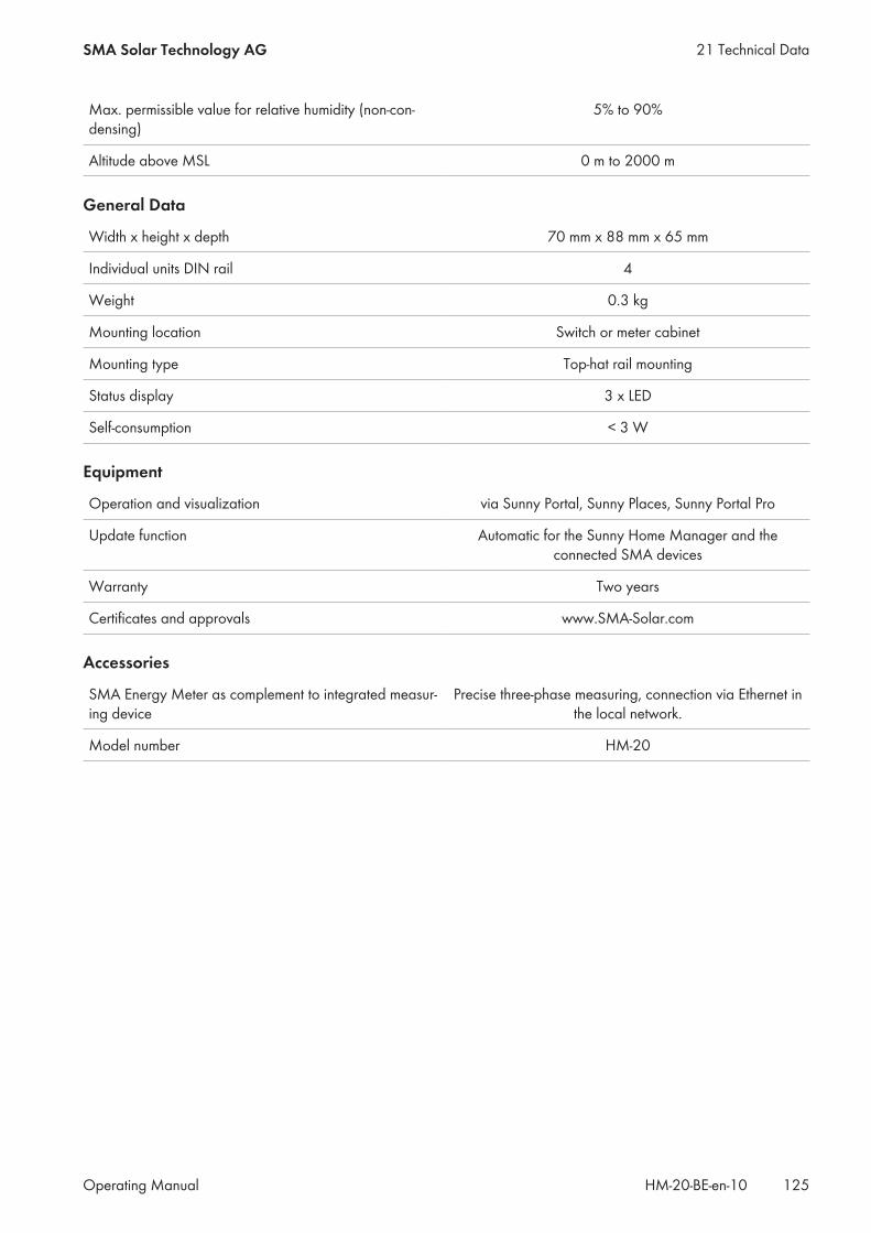
Max. permissible value for relative humidity (non-con-densing)
5% to 90%
Altitude above MSL 0 m to 2000 m
General Data
Width x height x depth 70 mm x 88 mm x 65 mm
Individual units DIN rail 4
Weight 0.3 kg
Mounting location Switch or meter cabinet
Mounting type Top-hat rail mounting
Status display 3 x LED
Self-consumption < 3 W
Equipment
Operation and visualization via Sunny Portal, Sunny Places, Sunny Portal Pro
Update function Automatic for the Sunny Home Manager and theconnected SMA devices
Warranty Two years
Certificates and approvals www.SMA-Solar.com
Accessories
SMA Energy Meter as complement to integrated measur-ing device
Precise three-phase measuring, connection via Ethernet inthe local network.
Model number HM-20
21 Technical DataSMA Solar Technology AG
Operating Manual 125HM-20-BE-en-10
22 ContactIf you have technical problems with our products, please contact the SMA Service Line. We require the followinginformation in order to provide you with the necessary assistance:
• Serial number and software package of the Sunny Home Manager• Manufacturer, serial number and firmware version of the radio-controlled socket• Name of the Sunny Home Manager system• Type of energy meters
DanmarkDeutschlandÖsterreichSchweiz
SMA Solar Technology AGNiestetalSunny Boy, Sunny Mini Central,Sunny Tripower: +49 561 9522‑1499Monitoring Systems(Kommunikationsprodukte):+49 561 9522‑2499Fuel Save Controller(PV-Diesel-Hybridsysteme):+49 561 9522-3199Sunny Island, Sunny Boy Storage,Sunny Backup, Hydro Boy:+49 561 9522-399Sunny Central,Sunny Central Storage:+49 561 9522-299SMA Online Service Center:www.SMA-Service.com
BelgienBelgiqueBelgiëLuxemburgLuxembourgNederland
SMA Benelux BVBA/SPRLMechelen+32 15 286 730SMA Online Service Center:www.SMA-Service.com
ČeskoMagyarországSlovensko
SMA Service PartnerTERMS a.s.+420 387 6 85 111SMA Online Service Center:www.SMA-Service.com
Türkiye SMA Service PartnerDEKOM Ltd. Şti.+90 24 22430605SMA Online Service Center:www.SMA-Service.com
France SMA France S.A.S.Lyon+33 472 22 97 00SMA Online Service Center :www.SMA-Service.com
ΕλλάδαΚύπρος
SMA Service PartnerAKTOR FM.Αθήνα+30 210 8184550SMA Online Service Center:www.SMA-Service.com
EspañaPortugal
SMA Ibérica Tecnología Solar, S.L.U.Barcelona+34 935 63 50 99SMA Online Service Center:www.SMA-Service.com
UnitedKingdom
SMA Solar UK Ltd.Milton Keynes+44 1908 304899SMA Online Service Center:www.SMA-Service.com
Italia SMA Italia S.r.l.Milano+39 02 8934-7299SMA Online Service Center:www.SMA-Service.com
BulgariaRomâniaSlovenijaHrvatska
SMA Service PartnerRenovatio Solar+40 372 756 599SMA Online Service Center:www.SMA-Service.com
22 Contact SMA Solar Technology AG
Operating ManualHM-20-BE-en-10126

United ArabEmirates
SMA Middle East LLCAbu Dhabi+971 2234 6177SMA Online Service Center:www.SMA-Service.com
India SMA Solar India Pvt. Ltd.Mumbai+91 22 61713888
SMA Solar (Thailand) Co., Ltd.
+66 2 670 6999
대한민국 SMA Technology Korea Co., Ltd.서울+82-2-520-2666
South Africa SMA Solar TechnologySouth Africa Pty Ltd.Cape Town08600SUNNY (08600 78669)International:+27 (0)21 826 0600SMA Online Service Center:www.SMA-Service.com
ArgentinaBrasilChilePerú
SMA South America SPASantiago de Chile+562 2820 2101
Australia SMA Australia Pty Ltd.SydneyToll free for Australia: 1800 SMA AUS(1800 762 287)International: +61 2 9491 4200
Other countries International SMA Service LineNiestetal00800 SMA SERVICE(+800 762 7378423)
22 ContactSMA Solar Technology AG
Operating Manual 127HM-20-BE-en-10