operating manual - grid-connect-box 12 - sma...
TRANSCRIPT
GRID-BOX-12-3-20-BE-en-11 | Version 1.1 ENGLISH
Operating ManualGRID-CONNECT-BOX 12

Legal Provisions SMA Solar Technology AG
2 GRID-BOX-12-3-20-BE-en-11 Operating Manual
Legal ProvisionsThe information contained in this document is the property of SMA Solar Technology AG. Publishing its content, either partially or in full, requires the written permission of SMA Solar Technology AG. Any internal company copying of the document for the purposes of evaluating the product or its correct implementation is allowed and does not require permission.
SMA WarrantyYou can download the current warranty conditions from the Internet at www.SMA-Solar.com.
TrademarksAll trademarks are recognized, even if not explicitly identified as such. A lack of identification does not mean that a product or symbol is not trademarked.The BLUETOOTH® word mark and logos are registered trademarks owned by Bluetooth SIG, Inc. and any use of these marks by SMA Solar Technology AG is under license.Modbus® is a registered trademark of Schneider Electric and is licensed by the Modbus Organization, Inc.QR Code is a registered trademark of DENSO WAVE INCORPORATED.Phillips® and Pozidriv® are registered trademarks of Phillips Screw Company.Torx® is a registered trademark of Acument Global Technologies, Inc.
SMA Solar Technology AG Sonnenallee 1 34266 Niestetal GermanyTel. +49 561 9522-0 Fax +49 561 9522-100 www.SMA.de E-mail: [email protected]© 2004 to 2016 SMA Solar Technology AG. All rights reserved.

SMA Solar Technology AG Table of Contents
Operating Manual GRID-BOX-12-3-20-BE-en-11 3
Table of Contents1 Information on this Document. . . . . . . . . . . . . . . . . . . . . . . . . . . . . . . . . . . . . . . . . . . . . . . . . . . . . 5
1.1 Validity . . . . . . . . . . . . . . . . . . . . . . . . . . . . . . . . . . . . . . . . . . . . . . . . . . . . . . . . . . . . . . . . . . . . . . . . . . . . . . 51.2 Target Group . . . . . . . . . . . . . . . . . . . . . . . . . . . . . . . . . . . . . . . . . . . . . . . . . . . . . . . . . . . . . . . . . . . . . . . . . 51.3 Additional Information . . . . . . . . . . . . . . . . . . . . . . . . . . . . . . . . . . . . . . . . . . . . . . . . . . . . . . . . . . . . . . . . . . 51.4 Symbols . . . . . . . . . . . . . . . . . . . . . . . . . . . . . . . . . . . . . . . . . . . . . . . . . . . . . . . . . . . . . . . . . . . . . . . . . . . . . 51.5 Typographies . . . . . . . . . . . . . . . . . . . . . . . . . . . . . . . . . . . . . . . . . . . . . . . . . . . . . . . . . . . . . . . . . . . . . . . . . 61.6 Nomenclature. . . . . . . . . . . . . . . . . . . . . . . . . . . . . . . . . . . . . . . . . . . . . . . . . . . . . . . . . . . . . . . . . . . . . . . . . 6
2 Safety . . . . . . . . . . . . . . . . . . . . . . . . . . . . . . . . . . . . . . . . . . . . . . . . . . . . . . . . . . . . . . . . . . . . . . . . 72.1 Intended Use . . . . . . . . . . . . . . . . . . . . . . . . . . . . . . . . . . . . . . . . . . . . . . . . . . . . . . . . . . . . . . . . . . . . . . . . . 72.2 Safety Information . . . . . . . . . . . . . . . . . . . . . . . . . . . . . . . . . . . . . . . . . . . . . . . . . . . . . . . . . . . . . . . . . . . . . 9
3 Scope of Delivery. . . . . . . . . . . . . . . . . . . . . . . . . . . . . . . . . . . . . . . . . . . . . . . . . . . . . . . . . . . . . . 104 Product Description . . . . . . . . . . . . . . . . . . . . . . . . . . . . . . . . . . . . . . . . . . . . . . . . . . . . . . . . . . . . 11
4.1 Grid-Connect-Box . . . . . . . . . . . . . . . . . . . . . . . . . . . . . . . . . . . . . . . . . . . . . . . . . . . . . . . . . . . . . . . . . . . . . 114.2 Type Label . . . . . . . . . . . . . . . . . . . . . . . . . . . . . . . . . . . . . . . . . . . . . . . . . . . . . . . . . . . . . . . . . . . . . . . . . . 13
5 Installation . . . . . . . . . . . . . . . . . . . . . . . . . . . . . . . . . . . . . . . . . . . . . . . . . . . . . . . . . . . . . . . . . . . 145.1 Storing the Grid-Connect-Box . . . . . . . . . . . . . . . . . . . . . . . . . . . . . . . . . . . . . . . . . . . . . . . . . . . . . . . . . . . . 145.2 Requirements for Mounting. . . . . . . . . . . . . . . . . . . . . . . . . . . . . . . . . . . . . . . . . . . . . . . . . . . . . . . . . . . . . . 145.3 Preparing the Mounting Location . . . . . . . . . . . . . . . . . . . . . . . . . . . . . . . . . . . . . . . . . . . . . . . . . . . . . . . . . 155.4 Transport. . . . . . . . . . . . . . . . . . . . . . . . . . . . . . . . . . . . . . . . . . . . . . . . . . . . . . . . . . . . . . . . . . . . . . . . . . . . 15
5.4.1 Transport Options . . . . . . . . . . . . . . . . . . . . . . . . . . . . . . . . . . . . . . . . . . . . . . . . . . . . . . . . . . . . . . . . . . . . . . .155.4.2 Transporting and Mounting the Grid-Connect-Box . . . . . . . . . . . . . . . . . . . . . . . . . . . . . . . . . . . . . . . . . . . . . .16
6 Electrical Connection . . . . . . . . . . . . . . . . . . . . . . . . . . . . . . . . . . . . . . . . . . . . . . . . . . . . . . . . . . . 176.1 Overview of the Connection Area . . . . . . . . . . . . . . . . . . . . . . . . . . . . . . . . . . . . . . . . . . . . . . . . . . . . . . . . 17
6.1.1 Components and Terminals . . . . . . . . . . . . . . . . . . . . . . . . . . . . . . . . . . . . . . . . . . . . . . . . . . . . . . . . . . . . . . . .176.1.2 Enclosure Openings in the Floor . . . . . . . . . . . . . . . . . . . . . . . . . . . . . . . . . . . . . . . . . . . . . . . . . . . . . . . . . . . .18
6.2 Deactivating All-Pole Disconnection . . . . . . . . . . . . . . . . . . . . . . . . . . . . . . . . . . . . . . . . . . . . . . . . . . . . . . . 186.3 Connecting the Multicluster-Box . . . . . . . . . . . . . . . . . . . . . . . . . . . . . . . . . . . . . . . . . . . . . . . . . . . . . . . . . . 186.4 Connecting the Utility Grid . . . . . . . . . . . . . . . . . . . . . . . . . . . . . . . . . . . . . . . . . . . . . . . . . . . . . . . . . . . . . . 196.5 Connecting the Control Cables . . . . . . . . . . . . . . . . . . . . . . . . . . . . . . . . . . . . . . . . . . . . . . . . . . . . . . . . . . 196.6 Mounting the Kick Plates . . . . . . . . . . . . . . . . . . . . . . . . . . . . . . . . . . . . . . . . . . . . . . . . . . . . . . . . . . . . . . . 20
7 Preparing the Multicluster System for Commissioning . . . . . . . . . . . . . . . . . . . . . . . . . . . . . . . . 218 Disconnecting the Grid-Connect-Box and Multicluster System from Voltage Sources. . . . . . . 229 Periodic Actions . . . . . . . . . . . . . . . . . . . . . . . . . . . . . . . . . . . . . . . . . . . . . . . . . . . . . . . . . . . . . . . 23
9.1 Removing the Protective Cover . . . . . . . . . . . . . . . . . . . . . . . . . . . . . . . . . . . . . . . . . . . . . . . . . . . . . . . . . . . 239.2 Mounting the Protective Cover . . . . . . . . . . . . . . . . . . . . . . . . . . . . . . . . . . . . . . . . . . . . . . . . . . . . . . . . . . . 249.3 Inserting the Cables . . . . . . . . . . . . . . . . . . . . . . . . . . . . . . . . . . . . . . . . . . . . . . . . . . . . . . . . . . . . . . . . . . . 259.4 Connection to Spring-Cage Terminals . . . . . . . . . . . . . . . . . . . . . . . . . . . . . . . . . . . . . . . . . . . . . . . . . . . . . 26
9.4.1 Connecting Power Cables to Spring-Cage Terminals . . . . . . . . . . . . . . . . . . . . . . . . . . . . . . . . . . . . . . . . . . . .269.4.2 Connecting Control Cables to Spring-Cage Terminals . . . . . . . . . . . . . . . . . . . . . . . . . . . . . . . . . . . . . . . . . . .27

Table of Contents SMA Solar Technology AG
4 GRID-BOX-12-3-20-BE-en-11 Operating Manual
10 Maintenance . . . . . . . . . . . . . . . . . . . . . . . . . . . . . . . . . . . . . . . . . . . . . . . . . . . . . . . . . . . . . . . . . .2810.1 Testing the Residual-Current Device . . . . . . . . . . . . . . . . . . . . . . . . . . . . . . . . . . . . . . . . . . . . . . . . . . . . . . . 2810.2 Testing the Surge Arrester . . . . . . . . . . . . . . . . . . . . . . . . . . . . . . . . . . . . . . . . . . . . . . . . . . . . . . . . . . . . . . 2910.3 Maintenance Work Every 12 Months . . . . . . . . . . . . . . . . . . . . . . . . . . . . . . . . . . . . . . . . . . . . . . . . . . . . . 29
11 Decommissioning . . . . . . . . . . . . . . . . . . . . . . . . . . . . . . . . . . . . . . . . . . . . . . . . . . . . . . . . . . . . . .3111.1 Disassembling the Grid-Connect-Box . . . . . . . . . . . . . . . . . . . . . . . . . . . . . . . . . . . . . . . . . . . . . . . . . . . . . . 3111.2 Disposing of the Grid-Connect-Box . . . . . . . . . . . . . . . . . . . . . . . . . . . . . . . . . . . . . . . . . . . . . . . . . . . . . . . 31
12 Technical Data. . . . . . . . . . . . . . . . . . . . . . . . . . . . . . . . . . . . . . . . . . . . . . . . . . . . . . . . . . . . . . . . .3213 Contact. . . . . . . . . . . . . . . . . . . . . . . . . . . . . . . . . . . . . . . . . . . . . . . . . . . . . . . . . . . . . . . . . . . . . . .35
SMA Solar Technology AG 1 Information on this Document
Operating Manual GRID-BOX-12-3-20-BE-en-11 5
1 Information on this Document1.1 ValidityThis document is valid for the device type "GRID-CONNECT-BOX 12.3-20" (Grid-Connect-Box 12).
1.2 Target GroupThe activities described in this document must be performed by qualified persons only. Qualified persons must have the following skills:
• Training in how to deal with the dangers and risks associated with installing and operating electrical devices and batteries
• Training in the installation and commissioning of electrical devices• Knowledge of and adherence to the local standards and directives• Knowledge of and compliance with this document and all safety information
1.3 Additional InformationLinks to additional information can be found at www.SMA-Solar.com:
1.4 Symbols
Document title Document typeMULTICLUSTER-BOX 12 Installation – circuitry overviewMULTICLUSTER-BOX 12 Operating manual
Symbol ExplanationIndicates a hazardous situation that, if not avoided, will result in death or serious injury
Indicates a hazardous situation that, if not avoided, can result in death or serious injury
Indicates a hazardous situation that, if not avoided, can result in minor or moderate injury
Indicates a situation that, if not avoided, can result in property damage
Information that is important for a specific topic or goal, but is not safety-relevant
☐ Indicates a requirement for meeting a specific goal☑ Desired result✖ A problem that might occur

1 Information on this Document SMA Solar Technology AG
6 GRID-BOX-12-3-20-BE-en-11 Operating Manual
1.5 Typographies
1.6 Nomenclature
Typography Application Examplebold • Display messages
• Parameter• Terminals• Slots• Elements to be selected or
entered
• Connect the neutral conductor to the spring-cage terminal N at terminal X301:6.
• Connect the line conductors to the spring-cage terminals L1, L2 and L3 at the terminals X301:8-10.
> • Connects several elements to be selected
–
[Button/Key] • Button on the device to be selected or pressed
• Press the [TEST] button.
Complete designation Designation in this documentGrid-Connect-Box12 Grid-Connect-BoxMulticluster-Box 12 Multicluster-Box
SMA Solar Technology AG 2 Safety
Operating Manual GRID-BOX-12-3-20-BE-en-11 7
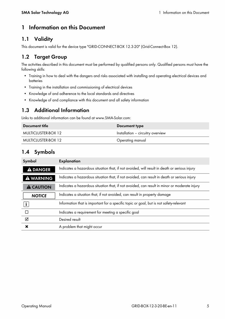
2 Safety2.1 Intended UseThe Grid-Connect-Box is an automatic transfer switch which enables the safe operation of the utility grid and an electricity generator as energy sources of an SMA multicluster system.
Figure 1: Circuitry principle of a multicluster system with the Grid-Connect-BoxThe technical connection requirements of the grid operator and the local standards and directives specify whether the multicluster system, in the event of grid failure, disconnects from the utility grid at all poles or only the line conductors. The Grid-Connect-Box is always supplied with an all-pole disconnection function. If all-pole disconnection is not permitted, the Grid-Connect-Box all-pole disconnection function must be deactivated(see Section 6.2, page 18).If the Grid-Connect-Box is used with all-pole disconnection, the utility grid must be either a TN-S, TN-C-S or TT system. If the Grid-Connect-Box is used without all-pole disconnection, the utility grid must be a TN-C-S system (for grounding in the multicluster system, see the Multicluster-Box operating manual). Do not exceed the maximum AC connection power of the Grid-Connect-Box. Cables with copper conductors must be used for the installation.

2 Safety SMA Solar Technology AG
8 GRID-BOX-12-3-20-BE-en-11 Operating Manual
In terms of interference immunity, the product is suitable for EMC environment A, and in terms of EMC emissions, it is suitable for EMC environment B* .The Grid-Connect-Box may only be commissioned in conjunction with the Multicluster-Box.The Grid-Connect-Box is designed for use at altitudes of up to 3000 m above Mean Sea Level. If you would like to use the Grid-Connect-Box at altitudes above 3000 m, contact Service (see Section 13, page 35). The Grid-Connect-Box is suitable for indoor use. The product may only be operated at temperatures between −25°C and +60°C.All work on the product must only be performed using appropriate tools and in compliance with the ESD protection regulations.Suitable personal protective equipment must be worn by all persons working on or with the product.Use this product only in accordance with the information provided in the enclosed documentation and with the locally applicable standards and directives. Any other application may cause personal injury or property damage. Alterations to the product, e.g. modifications or conversions, are only permitted with the express written permission of SMA Solar Technology AG. Unauthorized alterations will void guarantee and warranty claims and will usually void the operation license. SMA Solar Technology AG shall not be held liable for any damage caused by such alterations.Any use of the product other than that described in the Intended Use section does not qualify as the intended use.The enclosed documentation is an integral part of this product. Keep the documentation in a convenient place for future reference and observe all instructions contained therein.The type label must remain permanently attached to the product.
* In accordance with IEC 61439-1:2011

SMA Solar Technology AG 2 Safety
Operating Manual GRID-BOX-12-3-20-BE-en-11 9
2.2 Safety InformationThis Section contains safety information that must be observed at all times during work on or with the product.To prevent personal injury and property damage and to ensure long-term operation of the product, read this Section carefully and observe all safety information at all times.
Danger to life due to electric shockHigh voltages are present in the Grid-Connect-Box and the multicluster system. Touching live components results in death or serious injury due to electric shock.
• Disconnect the Grid-Connect-Box and multicluster system from all voltage sources before carrying out any work on the Grid-Connect-Box (see Section 8, page 22).
• Only operate the Grid-Connect-Box with its protective cover in place.• Work on the Grid-Connect-Box may only be performed by qualified persons.• Do not touch any live components in the Grid-Connect-Box or any other components in the multicluster system.
Risk of injury if the Grid-Connect-Box tips overThe Grid-Connect-Box is heavy and may tip over if not properly fastened to the support surface. This can result in injuries due to crushing.
• Upon installation, attach the Grid-Connect-Box to the support surface.
Risk of burns due to hot components Components and terminals inside the Grid-Connect-Box can become hot during operation. Touching hot components can cause burns.
• Only operate the Grid-Connect-Box with its protective cover in place.• Prior to removing the protective cover, let the Grid-Connect-Box cool down.
Effects of an emergency disconnectionEmergency disconnection of the Sunny Island triggers the uncontrolled shutdown of the system, resulting in any unsaved data being lost.
• Only use the emergency disconnection to avoid danger or consequential damage.• In the event of an emergency disconnection, always check whether any fuse elements in the Grid-Connect-Box,
such as circuit breakers, have tripped.If any fuse elements have tripped, reactivate these fuse elements.
3 Scope of Delivery SMA Solar Technology AG
10 GRID-BOX-12-3-20-BE-en-11 Operating Manual
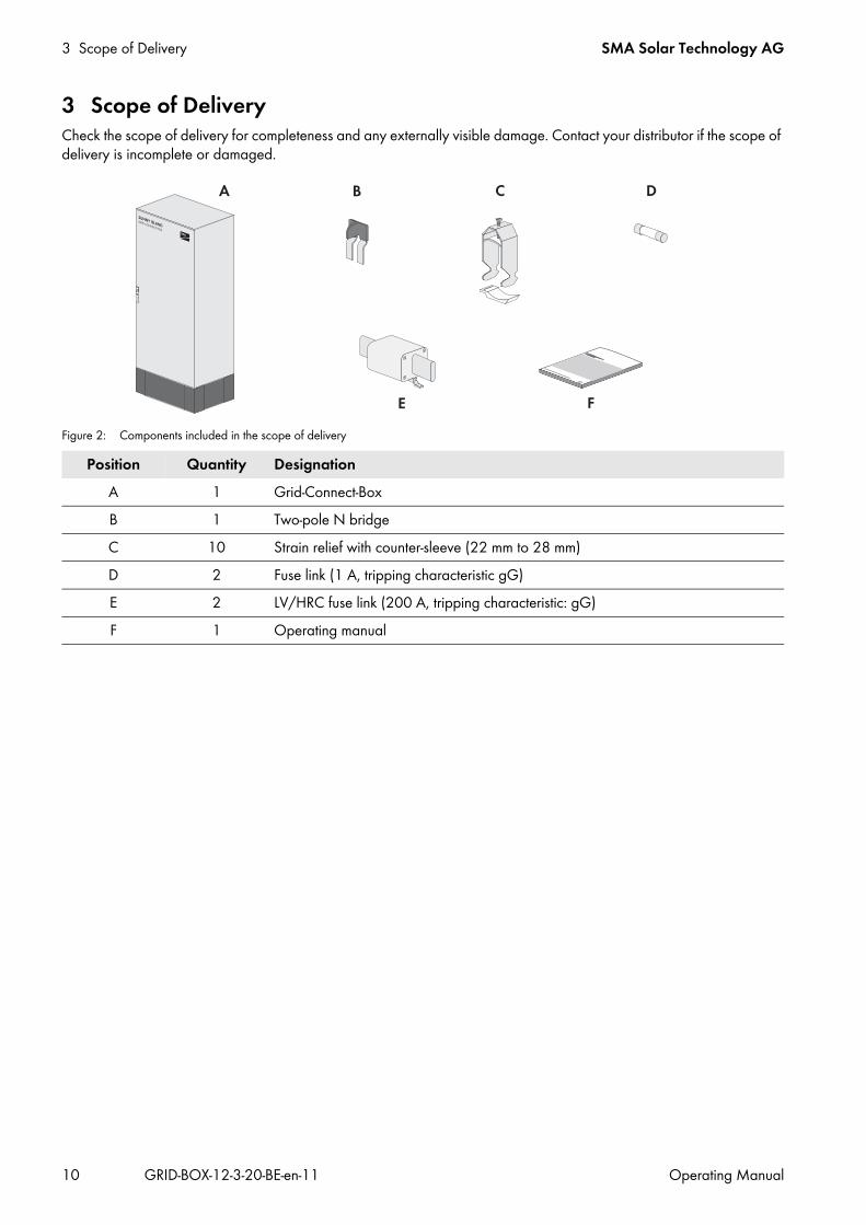
3 Scope of DeliveryCheck the scope of delivery for completeness and any externally visible damage. Contact your distributor if the scope of delivery is incomplete or damaged.
Figure 2: Components included in the scope of delivery
Position Quantity DesignationA 1 Grid-Connect-BoxB 1 Two-pole N bridgeC 10 Strain relief with counter-sleeve (22 mm to 28 mm)D 2 Fuse link (1 A, tripping characteristic gG)E 2 LV/HRC fuse link (200 A, tripping characteristic: gG)F 1 Operating manual

SMA Solar Technology AG 4 Product Description
Operating Manual GRID-BOX-12-3-20-BE-en-11 11
4 Product Description4.1 Grid-Connect-BoxThe Grid-Connect-Box is an automatic transfer switch which enables the safe operation of the utility grid and an electricity generator as energy sources of an SMA Multicluster System.
Figure 3: Grid-Connect-Box with cabinet door open
Position Designation ExplanationA Protective cover Prevents inadvertent contact with live components during
operation and thus protects from electric shocks. The protective cover must always be in position when the Grid-Connect-Box is in operation.
B Fuse holder 1 A Receptacle for cylindrical thermal fuses (1 A, tripping characteristic gG). The thermal fuses protect the connected conductors from excessive heat build-up due to overload or short circuits.
C Residual-current device Protects against electric shock and is always used in addition to existing protective measures such as insulation or protective grounding. As soon as a dangerous touch voltage occurs, the residual-current device disconnects all poles of the loads.This is achieved by means of a summation current transformer in the residual-current device which detects the electric currents in the conductors L1, L2, L3 and N. In the normal operating state, the sum of these currents equals zero. Under fault conditions a differential current is formed which trips the residual-current device.
4 Product Description SMA Solar Technology AG
12 GRID-BOX-12-3-20-BE-en-11 Operating Manual
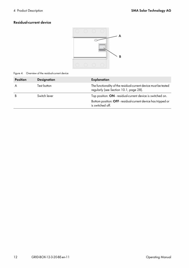
Residual-current device
Figure 4: Overview of the residual-current device
Position Designation ExplanationA Test button The functionality of the residual-current device must be tested
regularly (see Section 10.1, page 28).B Switch lever Top position: ON - residual-current device is switched on.
Bottom position: OFF - residual-current device has tripped or is switched off.

SMA Solar Technology AG 4 Product Description
Operating Manual GRID-BOX-12-3-20-BE-en-11 13
4.2 Type LabelThe type label clearly identifies the product. The type label is located on the right-hand side of the enclosure.You will find the following information on the type label:
• Address of SMA Solar Technology AG• Device type (Type)• Serial number (Serial No.)• Article number (Art No.)• Device-specific characteristics
You will require the information on the type label to use the product safely and when seeking customer support from Service.
Symbols on the type labelSymbol Explanation
Danger to life due to high voltagesThe product operates at high voltages. All work on the product must be carried out by qualified persons only.Risk of burns due to hot surfacesThe product can become hot during operation. Avoid contact during operation. Allow the product to cool down sufficiently before carrying out any work. Wear personal protective equipment such as safety gloves.Observe the documentationObserve all documentation supplied with the product.
WEEE designationDo not dispose of the product together with the household waste but in accordance with the locally applicable disposal regulations for electronic waste.CE markingThe product complies with the requirements of the applicable EU directives.Degree of protectionThe product is protected against interior dust deposits and water jets from all angles.
5 Installation SMA Solar Technology AG
14 GRID-BOX-12-3-20-BE-en-11 Operating Manual
5 Installation5.1 Storing the Grid-Connect-Box
• Store the Grid-Connect-Box in a dry place at an ambient temperature of between − 25°C and +60°C.
5.2 Requirements for MountingMounting Location☐ A firm, even support surface, e.g., a concrete foundation, must be available for mounting.☐ The mounting location must be suitable for the weight and dimensions of the Grid-Connect-Box (see Section 12
"Technical Data", page 32).☐ The mounting location must be clear and safely accessible at all times without any need for auxiliary equipment.☐ The mounting location must not hinder access to disconnection devices.☐ All local requirements concerning minimum passage widths and escape routes must be observed.☐ Climatic conditions must be met (see Section 12 "Technical Data", page 32).☐ The mounting location must be below 3000 m above MSL. If you would like to use the Grid-Connect-Box at altitudes
above 3000 m, contact Service (see Section 13, page 35).
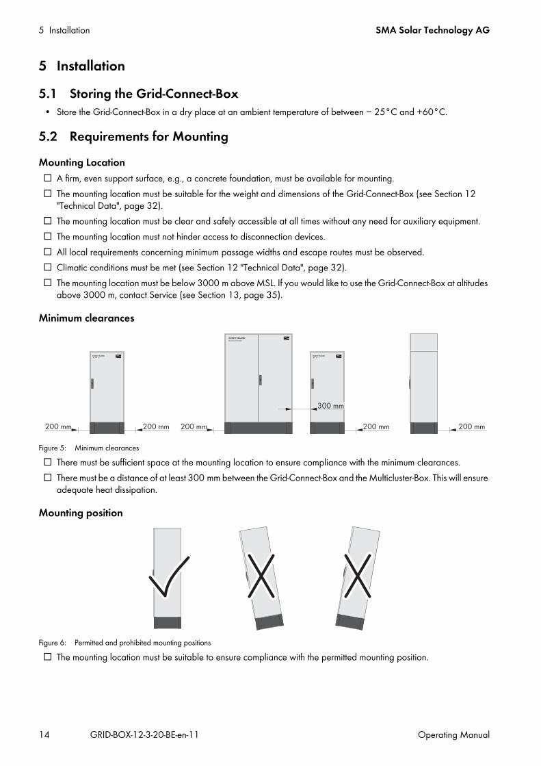
Minimum clearances
Figure 5: Minimum clearances☐ There must be sufficient space at the mounting location to ensure compliance with the minimum clearances.☐ There must be a distance of at least 300 mm between the Grid-Connect-Box and the Multicluster-Box. This will ensure
adequate heat dissipation.
Mounting position
Figure 6: Permitted and prohibited mounting positions☐ The mounting location must be suitable to ensure compliance with the permitted mounting position.
SMA Solar Technology AG 5 Installation
Operating Manual GRID-BOX-12-3-20-BE-en-11 15
5.3 Preparing the Mounting Location
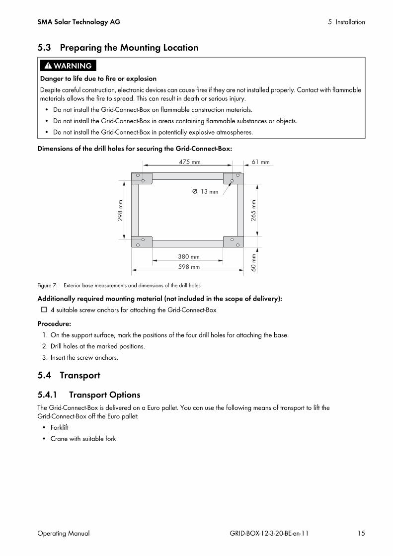
Dimensions of the drill holes for securing the Grid-Connect-Box:
Figure 7: Exterior base measurements and dimensions of the drill holes
Additionally required mounting material (not included in the scope of delivery):☐ 4 suitable screw anchors for attaching the Grid-Connect-Box
Procedure: 1. On the support surface, mark the positions of the four drill holes for attaching the base.2. Drill holes at the marked positions.3. Insert the screw anchors.
5.4 Transport5.4.1 Transport OptionsThe Grid-Connect-Box is delivered on a Euro pallet. You can use the following means of transport to lift the Grid-Connect-Box off the Euro pallet:
• Forklift• Crane with suitable fork
Danger to life due to fire or explosionDespite careful construction, electronic devices can cause fires if they are not installed properly. Contact with flammable materials allows the fire to spread. This can result in death or serious injury.
• Do not install the Grid-Connect-Box on flammable construction materials.• Do not install the Grid-Connect-Box in areas containing flammable substances or objects.• Do not install the Grid-Connect-Box in potentially explosive atmospheres.

5 Installation SMA Solar Technology AG
16 GRID-BOX-12-3-20-BE-en-11 Operating Manual
5.4.2 Transporting and Mounting the Grid-Connect-Box
Additionally required mounting material (not included in the scope of delivery):☐ 4 suitable screws for attaching the Grid-Connect-Box to the support surface
Procedure:1. Remove all fastening screws from the kick plates at the front and rear (TX 30).2. Remove the kick plates.
3. Retain the kick plates and the fastening screws for later use.4. Push the means of transport under the Grid-Connect-Box and transport the Grid-Connect-Box to the mounting
location.
Danger of crushing if the raised or suspended Grid-Connect-Box tips over or fallsThe Grid-Connect-Box can tip over or fall if it is lifted and transported carelessly or hastily. This can result in death or serious injury.
• Always transport the Grid-Connect-Box as close to the ground as possible.• Use a means of transportation which is suitable for the weight of the Grid-Connect-Box of 103 kg.• Transport the Grid-Connect-Box in an upright position.• Keep a safe distance from the Grid-Connect-Box at all times during transport.• Be aware of the center of gravity of the Grid-Connect-Box. The center of gravity of the Grid-Connect-Box is located
approximately in the center of the cabinet and is marked on the enclosure with the center of gravity symbol.
Damage to the Grid-Connect-Box due to inappropriate transportSetting the Grid-Connect-Box down on uneven surfaces can lead to the Grid-Connect-Box buckling and the doors no longer closing properly. This can lead to moisture or dust penetrating the Grid-Connect-Box.
• Do not set the Grid-Connect-Box down on unpaved, uneven surfaces.• Do not transport the Grid-Connect-Box with the kick plates mounted.
5.Risk of injury if the Grid-Connect-Box tips overThe Grid-Connect-Box is heavy and may tip over if not properly fastened to the support surface. This can result in injuries due to crushing.
• Attach the Grid-Connect-Box to the support surface using four suitable screws.

SMA Solar Technology AG 6 Electrical Connection
Operating Manual GRID-BOX-12-3-20-BE-en-11 17
6 Electrical Connection6.1 Overview of the Connection Area6.1.1 Components and Terminals
Figure 8: Overview of the connection area
Position Designation ExplanationA Terminals X310, X311 with spring-cage
terminalsSpring-cage terminals for connecting the control cables
B Surge arrester The signal light on the surge arrester must be checked regularly (see Section 10.2, page 29).
C Terminals X301:8-10 with spring-cage terminals L1, L2 and L3
For connecting the Multicluster-Box line conductors
D Terminal X301:7 with spring-cage terminal PE For connecting the Multicluster-Box grounding conductorE Terminal X301:6 with spring-cage terminal N For connecting the Multicluster-Box neutral conductorF Terminal X301:5 with spring-cage terminal N For connecting the utility grid neutral conductorG Terminal X301:4 with spring-cage terminal PE For connecting the utility grid grounding conductorH Terminals X301:1-3 with spring-cage
terminals L1, L2 and L3For connecting the utility grid line conductors

6 Electrical Connection SMA Solar Technology AG
18 GRID-BOX-12-3-20-BE-en-11 Operating Manual
6.1.2 Enclosure Openings in the Floor
Figure 9: Position of the enclosure openings
6.2 Deactivating All-Pole DisconnectionThe technical connection requirements of the grid operator and the local standards and directives specify whether the multicluster system, in the event of grid failure, disconnects from the utility grid at all poles or only the line conductors. The Grid-Connect-Box is always supplied with an all-pole disconnection function. If all-pole disconnection is not permitted, you must deactivate the Grid-Connect-Box all-pole disconnection function. To do this, insert the two-pole N bridge included in the scope of delivery as follows:Procedure:
• For use of the Grid-Connect-Box without all-pole disconnection, connect the spring-cage terminal N on X301:5 to the spring-cage terminal N on X301:6. To do this, plug the two-pole N bridge included in the scope of delivery into the spring-cage terminals from below.
6.3 Connecting the Multicluster-BoxCable requirements:☐ Conductor material: copper☐ Conductor cross-section: 50 mm² to 150 mm²☐ The power cables must be ground-fault- and short-circuit protected.☐ The line conductors, neutral conductor and grounding conductor must have the same cross-section.☐ The AC conductors and DC conductors must always be routed in separate cables.
Procedure:1. Insert the Multicluster-Box power cables into the Grid-Connect-Box (see Section 9.3, page 25).2. Connect the grounding conductor to the spring-cage terminal PE at terminal X301:7 (see Section 9.4.1, page 26).3. Connect the neutral conductor to the spring-cage terminal N at terminal X301:6.4. Connect the line conductors to the spring-cage terminals L1, L2 and L3 at the terminals X301:8-10.5. Ensure that a right-hand rotating magnetic field is present at the connection point of the Multicluster-Box.6. Provide for strain relief of the power cables in the spring-cage terminal by attaching them to the appropriate cable
support rail. Use the strain reliefs and counter-sleeves included in the scope of delivery for this.
Position ExplanationA Enclosure openings for the control cablesB Enclosure openings for the Multicluster-Box power cablesC Enclosure openings for the utility grid power cables
SMA Solar Technology AG 6 Electrical Connection
Operating Manual GRID-BOX-12-3-20-BE-en-11 19
6.4 Connecting the Utility GridCable requirements:☐ Conductor material: copper☐ The conductor cross-section must be selected according to the rated input power of the utility grid.☐ Conductor cross-section: 50 mm² to 150 mm²☐ The power cables must be ground-fault- and short-circuit protected.☐ The line conductors, neutral conductor and grounding conductor must have the same cross-section.☐ The AC conductors and DC conductors must always be routed in separate cables.
Procedure:1. Insert the Multicluster-Box power cables into the Grid-Connect-Box (see Section 9.3, page 25).2. Connect the grounding conductor to the spring-cage terminal PE at terminal X301:4 (see Section 9.4.1, page 26).3. Connect the neutral conductor to the spring-cage terminal N at terminal X301:5.4. Connect the line conductors to the spring-cage terminals L1, L2 and L3 at the terminals X301:1-3.5. Ensure that a right-hand rotating magnetic field is present at the grid-connection point.6. Provide for strain relief of the power cables in the spring-cage terminal by attaching them to the appropriate cable
support rail. Use the strain reliefs and counter-sleeves included in the scope of delivery for this.
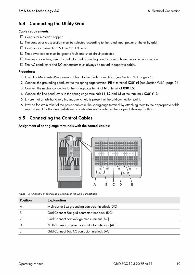
6.5 Connecting the Control CablesAssignment of spring-cage terminals with the control cables:
Figure 10: Overview of spring-cage terminals in the Grid-Connect-Box
Position ExplanationA Multicluster-Box grounding contactor interlock (DC)B Grid-Connect-Box grid contactor feedback (DC)C Grid-Connect-Box voltage measurement (AC)D Multicluster-Box generator contactor interlock (AC)E Grid-Connect-Box AC contactor interlock (AC)

6 Electrical Connection SMA Solar Technology AG
20 GRID-BOX-12-3-20-BE-en-11 Operating Manual
Cable requirements:☐ Conductor material: copper☐ Conductor cross-section: 1.5 mm² to 2.5 mm²☐ The AC conductors and DC conductors must always be routed in separate cables.
Procedure:1. Insert the control cables into the Grid-Connect-Box (see Section 9.3, page 25).2. Connect the control cables to the spring-cage terminals (see Section 9.4.2, page 27).
• X310:1,2: Multicluster-Box grounding contactor interlock• X310:4,5: Grid-Connect-Box grid contactor feedback• X311:1-4: Grid-Connect-Box voltage measurement• X311:6,7: Multicluster-Box generator contactor interlock• X311:8,9: Grid-Connect-Box AC contactor interlock
3. Ensure that the insulated conductors are firmly in place.
6.6 Mounting the Kick PlatesRequirement:☐ All installation work must be completed.
Procedure:1. Ensure that the power cables are secured with a strain relief.2. Insert the kick plates and attach using the fastening screws (TX 30, torque: 12 Nm).
Ground connection at terminals X310 and X311If the control cable between the Multicluster-Box and Grid-Connect-Box contains a grounding conductor, the grounding conductor terminal must not be connected on both sides.
SMA Solar Technology AG 7 Preparing the Multicluster System for Commissioning
Operating Manual GRID-BOX-12-3-20-BE-en-11 21
7 Preparing the Multicluster System for Commissioning
Requirements:☐ The Grid-Connect-Box must be correctly mounted (see Section 5, page 14).☐ All power cables must be correctly connected (see Section 6, page 17).☐ All control cables must be correctly connected (see Section 6.5, page 19).☐ All cables must be tightly enclosed by the membrane on the underside of the Grid-Connect-Box.☐ All power cables must be secured inside or outside the Grid-Connect-Box.☐ The floor of the Grid-Connect-Box must be closed with the base plates. All seals must be correctly positioned.☐ The kick plates must be attached to the base of the Grid-Connect-Box (see Section 6.6, page 20).
Procedure:1. Mount the protective cover (see Section 9.2, page 24).2. Close the Grid-Connect-Box.3. Ensure that the requirements for commissioning the Multicluster-Box are fulfilled (see Multicluster-Box operating
manual).
Service assignments for Sunny Island systemIn order to receive service assignments for the Sunny Island system, all system data must be recorded in the information sheet for Sunny Island systems during commissioning and made available to Service (for information sheet see www.SMA-Solar.com).

8 Disconnecting the Grid-Connect-Box and Multicluster System from Voltage Sources SMA Solar Technology AG
22 GRID-BOX-12-3-20-BE-en-11 Operating Manual
8 Disconnecting the Grid-Connect-Box and Multicluster System from Voltage Sources
1. Disconnect the loads.2. Stop the multicluster system at the master of the main cluster (see Sunny Island inverter documentation).3. Switch off all Sunny Island inverters (see Sunny Island inverter documentation). 4. Disconnect the PV main distribution board from voltage sources and secure against reconnection. 5. Disconnect the electricity generator and secure against reconnection.6. Disconnect the utility grid from the multicluster system at the grid-connection point and secure against reconnection.7. Open the Grid-Connect-Box.8. Open all fuse holders and residual-current devices in the Grid-Connect-Box.
10. Remove the protective cover (see Section 9.1, page 23).11. Ensure that no voltage is present in the Grid-Connect-Box.12. Cover and isolate any adjacent live components.
9.Risk of burns due to hot components Components and terminals inside the Grid-Connect-Box can become hot during operation. Touching hot components can cause burns.
• Prior to removing the protective cover, let the Grid-Connect-Box cool down.

SMA Solar Technology AG 9 Periodic Actions
Operating Manual GRID-BOX-12-3-20-BE-en-11 23
9 Periodic Actions9.1 Removing the Protective Cover
Procedure:1. Remove all four fastening screws from the protective cover
(TX 30).
2. Remove the protective cover.
3. Retain the protective cover and the fastening screws for later use.
Danger to life due to electric shockHigh voltages are present in the Grid-Connect-Box and the multicluster system. Touching live components can result in death or serious injury due to electric shock.
• Disconnect the Grid-Connect-Box and multicluster system from all voltage sources before carrying out any work on the Grid-Connect-Box (see Section 8, page 22).

9 Periodic Actions SMA Solar Technology AG
24 GRID-BOX-12-3-20-BE-en-11 Operating Manual
9.2 Mounting the Protective Cover1. Insert the protective cover into the Grid-Connect-Box.
2. Insert all four fastening screws and tighten them (TX 30, torque: 4 Nm).
SMA Solar Technology AG 9 Periodic Actions
Operating Manual GRID-BOX-12-3-20-BE-en-11 25
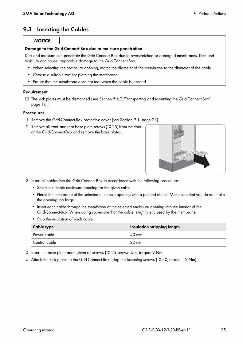
9.3 Inserting the Cables
Requirement:☐ The kick plates must be dismantled (see Section 5.4.2 "Transporting and Mounting the Grid-Connect-Box",
page 16).Procedure:
1. Remove the Grid-Connect-Box protective cover (see Section 9.1, page 23).2. Remove all front- and rear base plate screws (TX 25) from the floor
of the Grid-Connect-Box and remove the base plates.
3. Insert all cables into the Grid-Connect-Box in accordance with the following procedure:• Select a suitable enclosure opening for the given cable. • Pierce the membrane of the selected enclosure opening with a pointed object. Make sure that you do not make
the opening too large.• Insert each cable through the membrane of the selected enclosure opening into the interior of the
Grid-Connect-Box. When doing so, ensure that the cable is tightly enclosed by the membrane.• Strip the insulation of each cable.
4. Insert the base plate and tighten all screws (TX 25 screwdriver, torque: 9 Nm).5. Attach the kick plates to the Grid-Connect-Box using the fastening screws (TX 30, torque: 12 Nm).
Damage to the Grid-Connect-Box due to moisture penetrationDust and moisture can penetrate the Grid-Connect-Box due to overstretched or damaged membranes. Dust and moisture can cause irreparable damage to the Grid-Connect-Box.
• When selecting the enclosure opening, match the diameter of the membrane to the diameter of the cable.• Choose a suitable tool for piercing the membrane.• Ensure that the membrane does not tear when the cable is inserted.
Cable type Insulation stripping lengthPower cable 40 mmControl cable 20 mm

9 Periodic Actions SMA Solar Technology AG
26 GRID-BOX-12-3-20-BE-en-11 Operating Manual
9.4 Connection to Spring-Cage Terminals9.4.1 Connecting Power Cables to Spring-Cage Terminals
1. Insert the screwdriver into the clamping contact of the spring-cage terminal.
2. Push the screwdriver upwards in two stages as far as the stop. This pretensions the spring of the spring-cage terminal. The spring-cage terminal emits an audible click when the clamping contact is sufficiently pretensioned.
3. Insert the stripped insulated conductor into the spring-cage terminal until it reaches the stop. When doing so, ensure that no insulation is trapped in the terminal.
4. Press the screwdriver down and pull it out of the clamping contact.☑ The spring in the spring-cage terminal securely clamps the
insulated conductor.
5. Make sure that the insulated conductor is securely attached and that no insulation is trapped.

SMA Solar Technology AG 9 Periodic Actions
Operating Manual GRID-BOX-12-3-20-BE-en-11 27
9.4.2 Connecting Control Cables to Spring-Cage Terminals1. Using a screwdriver, press and hold down the orange break
contact of the spring-cage terminal.
2. Insert the stripped insulated conductor into the spring-cage terminal until it reaches the stop. When doing so, ensure that no insulation is trapped in the terminal.
3. Pull the screwdriver out of the clamping contact.☑ The spring in the spring-cage terminal securely clamps the
insulated conductor.
4. Make sure that the insulated conductor is securely attached and that no insulation is trapped.

10 Maintenance SMA Solar Technology AG
28 GRID-BOX-12-3-20-BE-en-11 Operating Manual
10 Maintenance10.1 Testing the Residual-Current Device
Requirement:☐ The utility grid must be connected to the multicluster system.
Procedure: 1. Stop the multicluster system at the master of the main cluster (see Sunny Island inverter operating manual).
2. Perform the following test on the Grid-Connect-Box residual-current device F339:• Press the [TEST] button.☑ The residual-current device trips.✖ The residual-current device does not trip?
• Disconnect the Grid-Connect-Box and multicluster system from voltage sources (see Section 8, page 22).• Contact Service (see Section 13, page 35). This will trigger the requisite spare parts order.
• If the residual-current device trips, wait for at least five seconds.• Reactivate the residual-current device. To do this, move the switch lever of the residual-current device to the ON
position.3. Start the multicluster system at the master of the main cluster (see Sunny Island inverter operating manual).4. Document the test result in accordance with the locally applicable standards and directives. This is your proof that
regular testing has taken place.
Test interval for residual-current devicesThe test interval for residual-current devices depends on the prevailing operating temperature.
• At prevailing operating temperatures of up to 40°C: every 6 months• At prevailing operating temperatures of above 40°C: every 3 months
Instruction for end usersBecause the protective cover remains in place during testing of the residual-current device, testing the residual-current device is not hazardous and can be performed by the end user. However, if the residual-current device does not trip, the Grid-Connect-Box and the multicluster system must be disconnected from voltage sources by a qualified person.
• Instruct the end user on the necessary procedure.• Inform the end user that the inspection interval must be complied with.• Inform the end user that in the event that the residual-current device does not trip, a qualified person must
perform the subsequent steps.
Supply of loads temporarily disconnectedDuring testing of the residual-current devices, the connection to the utility grid is temporarily disconnected. The supply to the loads is therefore also interrupted.
• Switch off sensitive loads prior to the test.
SMA Solar Technology AG 10 Maintenance
Operating Manual GRID-BOX-12-3-20-BE-en-11 29
10.2 Testing the Surge Arrester
Procedure: 1. Check whether the signal light on the surge arrester F340 is green or red.
If the signal light on the surge arrester is green, the surge arrester is in proper working order.If the signal light on the surge arrester is red, the surge arrester is defective.• Arrange for the surge arrester to be replaced immediately. Contact Service (see Section 13, page 35) for this.
2. Document the test result in accordance with the locally applicable standards and directives. This is your proof that regular testing has taken place.
10.3 Maintenance Work Every 12 Months
Test interval for surge arrestersThe test interval for surge arresters depends on the prevailing operating temperature.
• At prevailing operating temperatures of up to 40°C: every 6 months• At prevailing operating temperatures of above 40°C: every 3 months
Instruction for end usersBecause the protective cover remains in place during testing of the surge arresters, testing the surge arresters is not hazardous and can be performed by the end user. However, if a surge arrester is defective, the surge arrester must be replaced by a qualified person.
• Instruct the end user on the necessary procedure.• Inform the end user that the inspection interval must be complied with.• Inform the end user that in the event that the surge arrester is defective, a qualified person must perform the
subsequent steps.
Danger to life due to electric shockHigh voltages are present in the Grid-Connect-Box and the multicluster system. Touching live components can result in death or serious injury due to electric shock.
• Disconnect the Grid-Connect-Box and multicluster system from all voltage sources before carrying out any work on the Grid-Connect-Box (see Section 8, page 22).
The ambient conditions influence the maintenance intervalsThe mounting location and ambient conditions influence the maintenance intervals. More frequent cleaning and corrosion protection work may be necessary in adverse ambient conditions.
• If the Grid-Connect-Box is subject to adverse ambient conditions, SMA Solar Technology AG recommends carrying out maintenance work on the Grid-Connect-Box more frequently.
• SMA Solar Technology AG recommends an optical inspection every month to determine maintenance needs.

10 Maintenance SMA Solar Technology AG
30 GRID-BOX-12-3-20-BE-en-11 Operating Manual
Required maintenance materials and tools:Only those consumables and maintenance materials not normally included in the standard equipment of an electrically qualified person are listed below. It is assumed that standard tools and materials such as torque wrenches are available for all maintenance operations.☐ To repair minor surface corrosion damage: touch-up sticks, paint brushes, spray paint or, alternatively, 2K-PUR
acrylic paint (RAL color: 7035)☐ To repair large-surface corrosion damage: touch-up sticks or, alternatively, 2K-PUR acrylic paint (RAL color: 7035)☐ Abrasive cloth☐ Degreaser☐ For maintaining the seals: talcum, petroleum jelly or waxMaintenance work
• Check whether the inside of the Grid-Connect-Box is soiled or moist.If the inside of the Grid-Connect-Box is dirty, clean the Grid-Connect-Box.If the inside of the Grid-Connect-Box is moist or water has accumulated, dry the Grid-Connect-Box out.
• Check all Grid-Connect-Box power cables for discoloration or changes in the appearance of the insulation.If any power cables are discolored or the appearance of the insulation has changed, replace these power cables.
• Check all insulated conductors, terminals and fuse elements in the Grid-Connect-Box for discoloration or changes in the appearance of the insulation.If any insulated conductors, terminals or fuse elements in the Grid-Connect-Box are discolored or have changed in appearance, contact Service (see Section 13, page 35).
• Check whether the Grid-Connect-Box is free of corrosion damage.If the Grid-Connect-Box displays minor corrosion damage, treat the affected area as follows:• Sand the affected area.• Clean the affected area with degreaser.• Paint the affected area.If the Grid-Connect-Box displays large-scale corrosion damage, treat the entire surface as follows:• Sand the surface.• Clean the entire surface with degreaser.• Paint the entire surface.
• Check all door seals for damage.If a door seal is damaged, replace this door seal.
• Apply talcum, petroleum jelly or wax to the door seals. This will prevent frost damage.

SMA Solar Technology AG 11 Decommissioning
Operating Manual GRID-BOX-12-3-20-BE-en-11 31
11 Decommissioning11.1 Disassembling the Grid-Connect-Box
2. Remove all fastening screws from the kick plates at the front and rear. Retain the screws for later use. These screws will be needed later to reattach the kick plates.
3. Remove the protective cover and base plates.4. Remove all cables from the Grid-Connect-Box.5. Loosen and remove the Grid-Connect-Box fastening screws.6. Mount the protective cover and base plates.7. Close the Grid-Connect-Box doors.
9. Remount the kick plates on the Grid-Connect-Box.
11.2 Disposing of the Grid-Connect-Box• Dispose of the Grid-Connect-Box in accordance with the locally applicable disposal regulations for electronic waste.
1.High voltages are present in the Grid-Connect-Box and the multicluster system. Touching live components results in death or serious injury due to electric shock.• Disconnect the Grid-Connect-Box and multicluster system from voltage sources (see Section 8, page 22).
8.Danger of crushing if the raised or suspended Grid-Connect-Box tips over or fallsThe Grid-Connect-Box can tip over or fall if it is lifted and transported carelessly or hastily. This can result in death or serious injury.
• Always transport the Grid-Connect-Box as close to the ground as possible.• Use a means of transportation which is suitable for the weight of the Grid-Connect-Box of 103 kg. • Transport the Grid-Connect-Box in an upright position.• Keep a safe distance from the Grid-Connect-Box at all times during transport.• Be aware of the center of gravity of the Grid-Connect-Box. The center of gravity of the Grid-Connect-Box is
located approximately in the center of the cabinet and is marked on the enclosure with the center of gravity symbol.

12 Technical Data SMA Solar Technology AG
32 GRID-BOX-12-3-20-BE-en-11 Operating Manual
12 Technical DataUtility grid connection
Multicluster-Box connection
Grounding connection
Number of terminals 1 x three-phaseRated input power 138 kWRated operating voltage between L and N 230 VRated operating voltage between L1 and L2 400 VRated current / AC input current 3 x 200 ATerminals for connection N, PE, L1, L2, L3 Spring-cage terminalsMinimum conductor cross-section 50 mm²Maximum conductor cross-section 150 mm²Fuse LV/HRC 1Maximum permitted fuse rating 200 ASwitching capacity of backup fuse ≥ 25 kAMaximum unaffected short-circuit current / maximum relative rated short-circuit current
≤ 17 kA
Maximum permissible back-up fuse 200 A
Number of terminals 1 x three-phaseRated input power 138 kWRated operating voltage between L and N 230 VRated operating voltage between L1 and L2 400 VRated current / AC input current 3 x 200 ATerminals for connection N, PE, L1, L2, L3 Spring-cage terminalsMinimum conductor cross-section 50 mm²Maximum conductor cross-section 150 mm²Switching capacity of backup fuse ≥ 25 kAMaximum unaffected short-circuit current / maximum relative rated short-circuit current
≤ 17 kA
Maximum permissible back-up fuse 200 A
Terminal for grounding conductor connection Spring-cage terminalMinimum conductor cross-section 50 mm²Maximum conductor cross-section 150 mm²

SMA Solar Technology AG 12 Technical Data
Operating Manual GRID-BOX-12-3-20-BE-en-11 33
Auxiliary electric circuits
General data
Fuse 10x38 cylinder fuseMaximum permitted fuse rating F333 to F336: 1 ATerminals for connecting the control cables Spring-cage terminalMinimum conductor cross-section 0.75 mm²Maximum conductor cross-section 2.5 mm²
Number of line conductors 3Permitted grid configuration TN-S, TN-C-S or TTAC voltage range between L1 and N 172.5 V to 265 VAC voltage range between L1 and L2 300 V to 433 VRated frequency 50 HzFrequency range 45 Hz to 65 HzRated impulse withstand voltage 4 kV (2000 m)Width x height x depth (with base) 600 mm x 1400 mm x 435 mm
(incl. 200 mm base)Weight 103 kgMaximum operating altitude above mean sea level 3000 mInner subdivision Form 1 (no subdivision)Exterior structure Closed typeInstallation only fixed interior installation permittedConstruction type fixed componentsSuitable for use by electrically qualified persons or unqualified persons
Installation of the system and replacement of equipment by electrically qualified persons only /
actuation of test buttons and read-off of information by unqualified persons permitted
Measures for protection against electric shock Basic protection through insulation materials and covers / fault protection through grounding
conductors and short-circuit protection devices / personal protection through residual-current devices
Degree of protection of enclosure* IP55Degree of protection with open enclosure door* IP20Pollution degree at the mounting location** 3Pollution degree in the enclosure (micro-environment) 2Protection class*** 1Overvoltage category**** Overvoltage category 3
12 Technical Data SMA Solar Technology AG
34 GRID-BOX-12-3-20-BE-en-11 Operating Manual
Derating
Rated voltage / rated insulation voltage
EMC environment** EMC emissions, environment B(EMC Directive, Article 5 – Annex I.1.a)
Interference immunity, environment A(EMC Directive Article 5 – Annex I.1.b)
EC Declaration of Conformity YesOperating temperature range***** − 25°C to +60°CHumidity 0% to 100%
* in accordance with IEC 60529** in accordance with IEC 61439-1:2011
*** in accordance with IEC 417**** in accordance with EN 60664*****At operating temperatures above 40°C, the Sunny Island inverters reduce their output power (derating).
Output power / rated power at up to 40°C 100%Output power / rated power at 40°C to 60°C Derating according to power-temperature curve
(see Multicluster-Box operating manual)
Switch cabinet wiring L to N 250 V ACSwitch cabinet wiring L1 to L2 433 V ACAC auxiliary AC circuits 250 V ACDC auxiliary AC circuits 70 V DC
SMA Solar Technology AG 13 Contact
Operating Manual GRID-BOX-12-3-20-BE-en-11 35
13 ContactIf you experience any technical problems with our products, please contact the SMA Service Line. We require the following information in order to provide you with the necessary assistance:
• Multicluster-Box type• Multicluster-Box serial number• Grid-Connect-Box type and serial number• Type and number of Sunny Island inverters connected• Type of battery connected• Nominal battery capacity• Nominal battery voltage• Type and number of PV inverters connected• Type and number of loads connected• If an electricity generator is connected:
– Type– Power– Maximum current
In order to receive service assignments for the Sunny Island system, all system data must be recorded in the information sheet for Sunny Island systems during commissioning and made available to Service (for information sheet see www.SMA-Solar.com).
DanmarkDeutschlandÖsterreichSchweiz
SMA Solar Technology AGNiestetalSMA Online Service Center: www.SMA-Service.comSunny Boy, Sunny Mini Central, Sunny Tripower: +49 561 9522-1499Monitoring Systems (Kommunikationsprodukte): +49 561 9522-2499Fuel Save Controller (PV-Diesel Hybridsysteme): +49 561 9522-3199Sunny Island, Sunny Backup, Hydro Boy: +49 561 9522-399Sunny Central: +49 561 9522-299
BelgienBelgiqueBelgiëLuxemburgLuxembourgNederland
SMA Benelux BVBA/SPRLMechelen+32 15 286 730
ČeskoMagyarországSlovensko
SMA Service Partner TERMS a.s.+420 387 6 85 111
Polska SMA Polska+48 12 283 06 66
ΕλλάδαΚύπρος
SMA Hellas AEΑθήνα+30 210 9856666
EspañaPortugal
SMA Ibérica Tecnología Solar, S.L.U.Barcelona+34 935 63 50 99
France SMA France S.A.S.Lyon+33 472 22 97 00
BulgariaItaliaRomânia
SMA Italia S.r.l.Milano+39 02 8934-7299
United Kingdom SMA Solar UK Ltd.Milton Keynes+44 1908 304899
13 Contact SMA Solar Technology AG
36 GRID-BOX-12-3-20-BE-en-11 Operating Manual
United Arab Emirates
SMA Middle East LLCAbu Dhabi+971 2234 6177
India SMA Solar India Pvt. Ltd.Mumbai+91 22 61713888
대한민국 SMA Technology Korea Co., Ltd.서울+82-2-520-2666
SMA Solar (Thailand) Co., Ltd.
+66 2 670 6999
South Africa SMA Solar Technology South Africa Pty Ltd.Cape Town08600SUNNY (08600 78669)International: +27 (0)21 826 0600
ArgentinaBrasilChilePerú
SMA South America SPASantiago+562 2820 2101
Australia SMA Australia Pty Ltd.SydneyToll free for Australia: 1800 SMA AUS (1800 762 287)International: +61 2 9491 4200
Other countries International SMA Service LineNiestetalToll free worldwide: 00800 SMA SERVICE (+800 762 7378423)


www.SMA-Solar.comSMA Solar Technology