operating manual falcon 3 4 6 8
TRANSCRIPT

web: www.farmet.cz e-mail: [email protected]
IČ: 46504931 DIČ: CZ46504931
Farmet a. s. Jiřinková 276 552 03 Česká Skalice, CZ
telefon: +420 491 450 111 fax: +420 491 450 136 GSM: +420 774 715 738
OPERATING MANUAL
FALCON 3 | 4 | 6 | 8
Edition: 7 | effective from: 1.7.2020

Manual
FALCON 3 | 4 | 6 | 8
2 │ 99
Dear customer,
The FALCON disc sowing machines are high-quality products by Farmet a.s. Česká Skalice.
You can start to fully use the qualities of your machine after you have thoroughly studied the operating manual. The serial number of the machine is imprinted on the production label and recorded in the operating manual. Please use this serial number whenever you order spare parts in case of a repair. The production label is located on the central frame near the pole.
Use only spare parts for these machines according to the Spare Part Catalogue officially published by the producer, the company Farmet a.s. Česká Skalice. Possibilities of Use of Your Machine
The disc sowing machines are intended for areal sowing with the option to sow broad-line cultures into strips. The sowing machine is intended for sowing a wide range of farming products, such as cereal, pulses, oil bearing crops, clover crops, grass etc. The actual conditions for sowing individual farming products are stated below. The machine is intended for aggregation with tractors with the output from 90kW, 117 kW, 161 kW and from 205 kW according to the soil conditions and depth of sowing. The optimal working speed is 10 - 20 km/hour. The machine allows additional fertilising by granulated fertilisers while sowing.
Production label of the machine FALCON 3
Production label of the machine FALCON 4
Production label of the machine FALCON 6
Production label of the machine FALCON 8
FALCON 3
FALCON 4
FALCON 6
FALCON 8

Manual
FALCON 3 | 4 | 6 | 8
3 │ 99
CONTENT 1 QUICK START .................................................................................................................................................. 5 2 CRITICAL PARAMETERS OF THE MACHINE ..................................................................................................... 7 3 TECHNICAL PARAMETERS ............................................................................................................................... 7
Safety warning ................................................................................................................................................... 9 A. GENERAL INSTRUCTIONS FOR USE ................................................................................................................. 9
Protective equipment ...................................................................................................................................... 10 B. TRANSPORTING THE MACHINE .................................................................................................................... 10 C. MANIPULATING THE MACHINE BY LIFTING EQUIPMENT ............................................................................. 10 D. TRANSPORTING THE MACHINE ON GROUND COMMUNICATIONS .............................................................. 10 E. WORK SAFETY LABELS .................................................................................................................................. 11 4 DESCRIPTION OF THE MACHINE ................................................................................................................... 14
4.1 Working parts of the machine ............................................................................................................. 14 5 ASSEMBLY OF THE MACHINE AT THE CUSTOMER’S SITE ............................................................................. 17 6 PUTTING INTO OPERATION .......................................................................................................................... 17
6.1. Aggregation to the tractor ................................................................................................................... 18 6.2. Connecting the hydraulics .................................................................................................................... 19 6.3. Hydraulic diagram of the machine ....................................................................................................... 20 6.4. Connecting the elektronic unit ............................................................................................................. 21 6.5. Connecting the hydraulic motor of the fan .......................................................................................... 23 6.6. Proper connection to the tractor ......................................................................................................... 24
7. ELECTRONIC SYSTEM OF THE MACHINE ....................................................................................................... 26 7.1. Turning the sowing on and off ............................................................................................................. 27 7.2. Description of machine control by Müller electronics ......................................................................... 28 7.3. Description of the basic display ........................................................................................................... 28 7.4. Controlling hydraulics .......................................................................................................................... 29 7.5. Rail lines setting system ....................................................................................................................... 32 7.6. Reference data ..................................................................................................................................... 40
7.6.1 Creating an order ......................................................................................................................... 40 7.6.2 Levels of seeds in the hopper ...................................................................................................... 41
7.7. Setting passage sensors ....................................................................................................................... 41 7.7.1 Seeding sensors diagnostics ........................................................................................................ 44 7.7.2 Switching off the seed flow system sensor .................................................................................. 44 7.7.3 Designation of motors and dosers ............................................................................................... 45
8. UNFOLDING AND FOLDING MACHINE .......................................................................................................... 45 8.1. Unfolding the machine ......................................................................................................................... 46 8.2. Folding the machine ............................................................................................................................. 48
9. LOWERING AND LIFTING .............................................................................................................................. 50 10. FILLING UP THE SEED/FERTILIZER CONTAINER ............................................................................................. 50 11. SETTING THE FILLED SEEDS/FERTILIZER ........................................................................................................ 51 12. SETTING OF THE SOWING BATCH ................................................................................................................. 52
12.1. Screw dispecer for side dressing .......................................................................................................... 61 12.2. Setting the fine seeds sowing............................................................................................................... 62
13. SETTING VENTILATOR SPEED ACCORDING TO SEEDS ................................................................................... 63 14. ADJUSTMENT OF THE WORKING PARTS OF THE MACHINE ......................................................................... 64 15. ADJUSTING THE MACHINE WORK DEPTH ..................................................................................................... 64
15.1 Adjusting the machine by tps arms of the tractor ............................................................................... 65 15.2 Setting the sowing depth ..................................................................................................................... 66 15.3 Setting the down pressure of the sowing bodies ................................................................................. 67 15.4 Setting the leveller behind the seed boots .......................................................................................... 69 15.5 Adjusting the working depth of the front section ................................................................................ 70 15.6 Adjusting of the levelling ...................................................................................................................... 73 15.7 Setting of the markers .......................................................................................................................... 74 15.8 Setting of the deep fertilizing disc ........................................................................................................ 75
16. ERRORS ......................................................................................................................................................... 76 17. COMPLETION OF SOWING ............................................................................................................................ 88 18. MAINTENANCE AND REPAIRS OF THE MACHINE.......................................................................................... 90
18.1. Replacement of worn discs ................................................................................................................. 90 18.2. Maintenance plan ................................................................................................................................ 91

Manual
FALCON 3 | 4 | 6 | 8
4 │ 99
18.3. Machine lubrication schedule .............................................................................................................. 95 18.4. Manipulation with lubricans ................................................................................................................ 95 18.5. The pressure in the tyres ..................................................................................................................... 96 18.6. Recommended tightening torques of bolting ...................................................................................... 97
19. STORING THE MACHINE ............................................................................................................................... 97 20. PROTECTION OF ENVIRONMEN .................................................................................................................... 97 21. DISPOSAL OF THE MACHINE AFTER THE END OF ITS USABLE LIFE ............................................................... 97 22. MAINTENANCE AND TERMS OF GUARANTEE............................................................................................... 98
22.1. Maintenance ........................................................................................................................................ 98 22.2. Guarantee ............................................................................................................................................ 98

Manual
FALCON 3 | 4 | 6 | 8
5 │ 99
1 QUICK START 0 Safety warning 9
1 Pull the Falcon with the pulling device 18
2 Connect the return hydraulic hose 24
3 Connect the other hydraulic hoses 19
4 Connect the 7-pin cable for the road lights of the machine
5 Connect the machine electronics with the pulling vehicle. 21
6 Lift the front supporting leg of the machine and secure it
7 Release the pins for unfolding the front section 46
8 Open the valve for unfolding (blue marking) 46
9 Open the valve for lifting the front preparatory section (yellow marking) 50
10 Use the main switch to switch on the seed drill terminal
11 Unfold the machine using the hydraulic circuit and the control terminal 46
12 Set the pressure using the pressure reducing valve 68
13 Check the seed cleanliness 88
14 Check for leakage of the planer in the seedbed 88
15 Check the flow of the fertilizer hoses
16 Check the seed hose for continuity
17 Pour the seed 50
18 Pour the fertilizer 50
19 Check and adjust the seeder plane 65
20 Set the lower end of the tractor's TPS 65
21 Set the sowing depth 66
22 Adjust the depth of the front section 70
23 Set the dose in the electronics 58
24 Set the value on the doser 52
25 Perform a test shot 59
26 Enter the value of the weighed sample into the terminal 59
27 Check that the seeding speed range displayed on the terminal is optimal: 1.5-20 km/h 59
28 Set sensor sensitivity according to the table in the manual 41
29 Set the priority on the fan's hydraulic circuit
30 Adjust the oil flow for the fertilizer hydromotor 19
31 Set the fan speed, by seed and batch 63
32 Set the required hydraulic functions - indicators, track markers, etc. 30
33 Set the required pressure on the seedbed, depending on the soil conditions (20-60bar). 68

Manual
FALCON 3 | 4 | 6 | 8
6 │ 99

Manual
FALCON 3 | 4 | 6 | 8
7 │ 99
2 CRITICAL PARAMETERS OF THE MACHINE
The machine is designated for sowing common cereals and broad-line cultures in aggregation with an agricultural wheel or caterpillar tractor. Another type of use exceeding the determined purpose is forbidden.
(x) The machine is only operated by one person – the tractor driver.
(x) The operator must not use the machine for other purposes, particularly: (x) For transporting people and animals on the construction of the machine, (x) For transporting load on the construction of the machine, (x) Aggregation of the machine with other tractive equipment than stated in Chapter „6.1./P.18“.
3 TECHNICAL PARAMETERS Tab. 1 – Technical parameters of the machine
PARAMETERS FALCON 3 FALCON 4 FALCON 6 FALCON 8
Working width (mm) 3000 4 000 6 000 8 000
Transport width (mm) 3 000 3 000 3 000 3 000
Transport height (mm) 3 300 3 300 3 300 4 000
Total length of the machine (mm) 7 500 7 500 7 500 7 500
Working depth (mm) 0 – 100 0 – 100 0 – 100 0 – 100
Container capacity without fertilization ( l ) 4000 4000 4000 4000
Container capacity with fertilization ( l ) (ratio 40 : 60) 6000 6000 6000 8500
Filling height of the container (mm) 2650 2 650 2 650 3 400
Dimensions of the filling opening w/out fertilization (m) 2x0,52 / 1,2x0,52 2x0,52 / 1,2x0,52 2x0,52 / 1,2x0,52 2x0,52 / 1,2x0,52
Number of drill coulters (spacing 125 / 150 mm) 24/20 32 / 26 48 / 40 64 / 52
Number of fertilizer boots (spacing 250 / 300 mm) 12/10 16 / 13 24 / 20 32 / 26
Pressure of drill coulters / fertilizer boots (kg) 50 -115 / až 200 50 -115 / až 200 50 -115 / až 200 50 -115 / až 200
Diameter of the sowing disk, two-disk coulter / press-wheel (mm)
355 / 340 355 / 340 355 / 340 355 / 340
Diameter of the sowing disk, single-disk coulter / press-wheel (mm)
410 / 690 410 / 690 410 / 690 410 / 690
Number of discs
490
Front 12 16 25 34
Rear 11 15 24 33
Number of chisels of 2-row section, depth 200mm (spacing 250 / 300 mm)
12/10 16 / 13 24 / 20 32 / 26
Number of chisels of 3-row section, depth 200mm (spacing 250 / 300 mm)
12/10 16 / 13 24 / 20 32 / 26
Number of chisels of 2-row section, depth 300mm (spacing 375 mm)
8 16 24 32
Working capacity (ha/h) 3 - 4,5 4 – 6 6 - 9 8 - 12
Pulling vehicle (kW) 92 / 125 117 / 160 * 161 / 220 * 205 / 280 *
Working speed (km/h) 10 – 20 10 – 20 10 – 20 10 – 20
Maximum transport speed (km/h) 25 25 25 25
Maximum slope accessibility (°) 6 6 6 6
Tyre dimensions 405/70-20 405/70-20 405/70-20 405/70-20
Type of brakes / distribution 1) air / two-line*** air / two-line*** air / two-line*** air / two-line***
Required pressure (kPa) 8,5 8,5*** 8,5*** 8,5***
Number of hydraulic circuits / pressure (bar) 9 / 200 3 / 200 3 / 200 3 / 200
Number of quick-coupling devices / type 5 / ISO 12,5 5 / ISO 12,5 5 / ISO 12,5 5 / ISO 12,5
Non-pressure return line (max. 5 bar) 1 / ISO 20 1 / ISO 20 1 / ISO 20 1 / ISO 20
Hydraulic fan oil flow ( l/min) 30 - 40 30 - 40 30 - 40 30 - 40
Oil flow for machine control (l/min) 50 - 60 50 - 60 50 - 60 50 - 60
Electric system requirement 12 V DC / 40 A 12 V DC / 40 A 12 V DC / 40 A 12 V DC / 40 A
Tractor suspension requirement TPS kat. 3 TPS kat. 3 TPS kat. 3 TPS kat. 3
Machine weight without fertilization (kg) 4 830 – 5840** 5 340 – 6 580** 6 800 – 8 000** 8 440 – 9 950**
Machine weight with fertilization (kg) 5 630 – 6140** 6 630 – 8 420** 8 000 – 9 860** 9 600 – 12 100**
* recommended pulling vehicle, the actual pulling force may significantly change according to the selected version of the machine, processing depth, soil conditions, inclination of land, wear and tear of the working parts and their adjustment
** weight of the machine according to accessories
*** hydraulic brake alternative / operating pressure 130±5 bar
Technical Advice! 1) Transport/Brake System: Follow the national regulations valid for transportation of machines on public roads. Check the legal provisions valid in the country and regulations on maximum permissible total axle weights and loads and also on the necessary potential use of a brake system. If you have any further questions, please contact our sales representative.

Manual
FALCON 3 | 4 | 6 | 8
8 │ 99
PARAMETERS FALCON 3 Compact FALCON 4 Compact
Working width (mm) 3000 4 000
Transport width (mm) 3 000 3 000
Transport height (mm) 2 800 2 800
Total length of the machine (mm) 7 000 7 000
Working depth (mm) 0 – 100 0 – 100
Container capacity ( l ) 3000 3000
Filling height of the container (mm) 2600 2600
Dimensions of the filling opening (m) 0,52x1,92 0,52x1,92
Number of drill coulters (150 mm) 20 26
Pressure of drill coulters / fertilizer boots (kg) 50 -115 50 -115
Diameter of the sowing disk (mm) 355 355
Number of discs 23 31
Working capacity (ha/h) 3 - 4,5 4 – 6
Pulling vehicle (kW) 92 / 125 117 / 160 *
Working speed (km/h) 10 – 20 10 – 20
Maximum transport speed (km/h) 25 25
Maximum slope accessibility (°) 6 6
Tyre dimensions 7,5-16 7,5-16
Type of brakes / distribution 1) air / two-line*** air / two-line***
Number of hydraulic circuits / pressure (bar) 2 / 210 2 / 200
Number of quick-coupling devices / type 4 / ISO 12,5 4 / ISO 12,5
Non-pressure return line (max. 5 bar) 1 / ISO 20 1 / ISO 20
Hydraulic fan oil flow ( l/min) 30 - 40 30 - 40
Oil flow for machine control (l/min) 30 30
Electric system requirement 12 V DC / 25 A 12 V DC / 25 A
Tractor suspension requirement TPS kat. 2 a 3 TPS kat. 2 a 3
Machine weight without (kg) 3 800 4 400
* recommended pulling vehicle, the actual pulling force may significantly change according to the selected version of the machine, processing depth, soil conditions, inclination of land, wear and tear of the working parts and their adjustment

Manual
FALCON 3 | 4 | 6 | 8
9 │ 99
SAFETY WARNING
A. GENERAL INSTRUCTIONS FOR USE
A.1 (x) The machine is produced in compliance with the latest technological conditions and approved safety regulations. However, the use of the machine may still cause injuries to the user or third persons or damage to the machine or occurrence of other material damages.
A.2 (xx) Use the machine only in a technically unexceptionable condition, in compliance with its purpose, with awareness of potential risks and observance of safety instructions stated in this manual! The Manufacturer is not liable for damages caused by the use of the machine that is in contradiction with the limit parameters of the machine (p. 7) and with the instructions for the use of the machine (Chapter A and 3). The User bears the risk. Immediately eliminate all defects that could have a negative impact on safety!
A.3 (7) The machine may only be operated by a person authorized by the owner under the following conditions:
(8) He or she must have a valid driving licence in the relevant category,
(9) He or she must be verifiably informed on the safety rules of working with the machine and must have command of the operation of the machine in practice,
(10) The machine must not be operated by a minor (minors),
(11) He or she must understand the meaning of warning symbols placed on the machine. Respecting the symbols is important for a safe and reliable operation of the machine.
A.4 (12) Maintenance and service repairs may only be performed by a person:
(13) Authorized by the owner,
(14) Trained in an engineering field with the knowledge of repairs of similar machinery,
(15) Verifiably informed on the safety rules of working with the machine,
(16) With a driving licence in the relevant category for repairs of the machine attached to a tractor.
A.5 (17) The operator of the machine must ensure safety of other people during the work with the machine and its transportation.
A.6 (18) During machine work in the field or during transport, the operator must control the machine from the tractor's cabin.
A.7 (19) The operator may only enter the construction of the machine when the machine is off and secured against movement only in order to:
(20) adjust the working parts of the machine,
(21) repair and maintain the machine,
(29) release or secure the ball valves of the axle,
(27) secure the ball valves of the axle before tilting the side frame,
(28) adjust the working parts of the machine after opening the side frame.
A.8 (xxx) When climbing onto the machine, do not step on the tyres of the rolls or other revolving parts as they may roll over and you can seriously hurt yourself if you fall down.
This warning symbol warns against an imminent dangerous situation that could lead to death or serious injury.
This warning symbol warns against a dangerous situation that could lead to death or serious injury.
This warning symbol warns against a situation that could lead to a small or minor injury. It also points out dangerous tasks related to the activity that could lead to an injury.

Manual
FALCON 3 | 4 | 6 | 8
10 │ 99
A.9 (22) Any changes or adjustments of the machine may only be performed with a written consent of the producer. The producer is not responsible for any potential damages occurred as a result of non-compliance with this instruction. The machine must always be equipped with the prescribed accessories, equipment and gear including the safety labels. All warning and safety signs must be always legible and at their positions. They must be replaced if damaged or lost without delay.
A.10 (23) The operating manual and the requirements of the safety at work must be always available to the operator.
A.11 (24) When operating the machine, the operator must not consume alcohol, medicine, narcotic and hallucinogenic substances that reduce attention and coordination abilities. If the operator has to take medicine prescribed by the physician or if he or she uses over the counter medicine, he or she must be informed by the physician whether he or she is able to reliably and safely operate the machine under these circumstances.
PROTECTIVE EQUIPMENT For the operation and maintenance use:
Close-fitting clothing
Protective gloves and goggles for protection from dust and sharp parts of the machine
B. TRANSPORTING THE MACHINE
B.1 (1) The vehicle intended for the transportation of the machine must have at least the same bearing capacity as the weight of the transported machine is. The total weight of the machine is stated on the production label.
B.2 (2) The dimensions of the transported machine including the vehicle must comply with valid regulations for traffic on ground communications (decrees, acts).
B.3 (3) The transported machine must be always attached to the vehicle so that it cannot be released during transportation.
B.4 (4) The carrier is responsible for damages caused by the release of incorrectly or insufficiently attached machine to the vehicle.
C. MANIPULATING THE MACHINE BY LIFTING EQUIPMENT
C.1 (1) The lifting equipment and binding instruments intended for manipulation with the machine must have at least the same bearing capacity as the weight of the manipulated machine is.
C.2 (2) The machine may only be attached for manipulation in designated places marked by stick-on labels
showing a “chain“.
C.3 (3) When attached (suspended) in designated places, it is not allowed to move in the area of potential reach of the manipulated machine.
D. TRANSPORTING THE MACHINE ON GROUND COMMUNICATIONS
Transport Position of FALCON
Attach the machine to the tractor by hanging with the use of the two-point suspension equipment (TPS 3).
The side frames must be folded in the vertical position. The machine must be equipped with removable shields displaying the boundaries, functional lighting
and a board of rear label for slow vehicles (pursuant to ECE No.69). The lighting must be turned on when in operation on ground communications. The tractors must be equipped with a special light appliance with orange colour that must be turned
on when in operation on ground communications. The operator must drive with increased caution and consideration for other participants of the traffic.

Manual
FALCON 3 | 4 | 6 | 8
11 │ 99
The operator must secure the arms of the rear TPS of the tractor in the transport position when operating on ground communications. At the same time, the arms of the rear TPS of the tractor must be secured against swinging sideways.
It is strictly forbidden to transport people or load on the machine or connect another machine, semi-trailer or additional equipment to it.
The maximum transport speed during travelling on roads is 25 km/hour. Ban of transport with decreased visibility!
The machine may only be driven on roads when equipped with air brakes (the customer receives a certificate of roadworthiness). Otherwise, it is prohibited to drive the machine on roads!
E. WORK SAFETY LABELS
Warning safety labels are used for the protection of the operator. The following applies generally: A) Strictly observe the warning safety labels. B) All safety instructions also apply to other users. C) If the aforementioned “SAFETY LABEL” located on the machine is damaged or destroyed, THE OPERATOR MUST REPLACE IT WITH A NEW ONE!!!
The position, appearance and exact meaning of work safety labels on the machine are given in the following tables (Tab.2/p.11-12) and the picture (Picture 1,2/p.13).
Tb.2 - Self-adhesive warning safety labels located on the machine
WARNING SAFETY LABEL TEXT TO THE LABEL POSITION ON THE
MACHINE
Read carefully the operating manual before manipulation with the machine.
Observe the instructions and safety rules when operating the machine.
P 1 H
Driving the machine and transportation on its construction is strictly forbidden. P 37 H
When connecting and disconnecting, do not enter the area between the tractor and the machine. Do not enter that area unless the
tractor and the machine are not moving and the engine is off.
P 2 H
Stay beyond reach of the set Tractor – Agricultural Machine when the tractor
engine is running. P 6 H
Secure the axle of the machine against an unexpected drop before its transportation. P 13 H
Secure the machine against unwanted movement. P 52 H
Manual
FALCON 3 | 4 | 6 | 8
12 │ 99
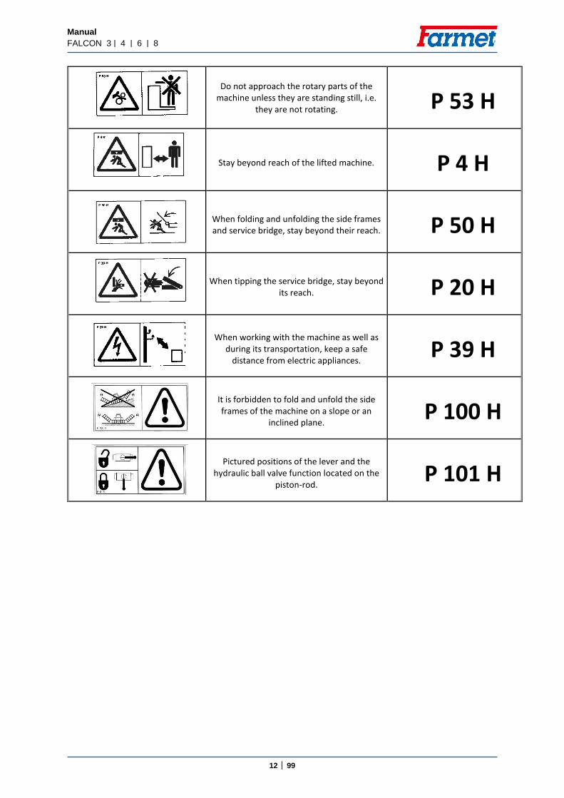
Do not approach the rotary parts of the
machine unless they are standing still, i.e. they are not rotating. P 53 H
Stay beyond reach of the lifted machine. P 4 H
When folding and unfolding the side frames and service bridge, stay beyond their reach. P 50 H
When tipping the service bridge, stay beyond its reach. P 20 H
When working with the machine as well as
during its transportation, keep a safe distance from electric appliances.
P 39 H
It is forbidden to fold and unfold the side frames of the machine on a slope or an
inclined plane. P 100 H
Pictured positions of the lever and the
hydraulic ball valve function located on the piston-rod.
P 101 H

Manual
FALCON 3 | 4 | 6 | 8
13 │ 99
Picture 1
Picture 2
P 100 H P 101 H
P 1 H P 2 H P 6 H
P 20 H P 50 H
P 39 H P 37 H P 4 H
P 39 H P 37 H P 4 H
P 50 H P 37 H
P 52 H P 53 H
P 20 H P 50 H
P 13 H P 20 H
P 20 H
P 52 H P 53 H
P 50 H P 37 H
P 39 H P 37 H P 4 H

Manual
FALCON 3 | 4 | 6 | 8
14 │ 99
4 DESCRIPTION OF THE MACHINE
The FALCON disc sowing machine is designed as semi-carried and folding. It is connected to the tractor using
a drawbar with pins of Cat III in the bottom arms of the tractor three-point suspension (TPS). In the front, there is a preparatory section for soil processing and levelling larger unevenness followed by a pneumatic-tyred ramming roller that levels and compacts soil in front of the sowing bodies. Then there is a leveller installed in the axis of each sowing body. At the end there are sowing bodies with compacting wheels and a leveller. Some of the tyres of the roller are also used for transport in the transport position. The seed container is equipped by a sowing mechanism commonly used in the standard ACCORD pneumatic sowing machines. There is also possibility to have Farmet Dispenser (Roller replacement system). The seeds are carried by air flow through seed tubes to the sowing body where it is placed in the soil in rows. The soil is then compacted by the wheel and levelled out with the leveller. The seeding mechanism is driven by electric motors. The fan for the transport of seeds is driven by hydraulic motor from the hydraulic circuit of the tractor. The machine is equipped with central markers and markers of rail lines. The electronic system of the machine allows checking the functions of the machine, regulation of the sowing batch and formation of rail lines. The transport wheels may be equipped with pneumatic brakes or hydraulic brakes.
4.1 WORKING PARTS OF THE MACHINE
Picture 3.1 – Working parts of the machine FALCON PRO
4.1.1 Drawbar with a collapsible resting leg 4.1.5 Leveller section 4.1.2 Front preparatory section 4.1.6 Sowing bodies with press-wheels 4.1.3 Disk fertilizing section 4.1.7 Leveller after the sowing bodies 4.1.4 Pneumatic-tyred flotation roller 4.1.8 Markers
Seed hopper with moveable orifice plate Easy release of fertilizer distribution
Seed / fertilizer Seed hopper with
moveable orifice plate
4.1.1 4.1.3 4.1.4 4.1.5
4.1.2 4.1.6
4.1.8
4.1.7
Manual
FALCON 3 | 4 | 6 | 8
15 │ 99
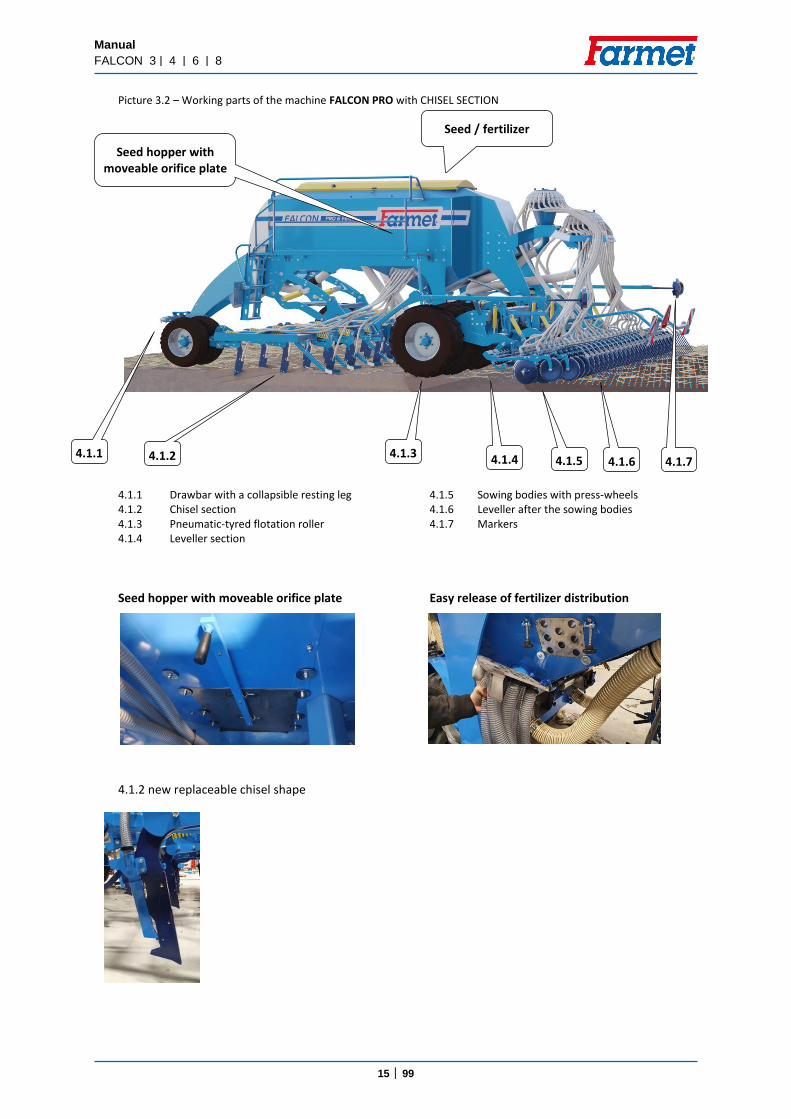
Seed / fertilizer
Seed hopper with moveable orifice plate
Picture 3.2 – Working parts of the machine FALCON PRO with CHISEL SECTION 4.1.1 Drawbar with a collapsible resting leg 4.1.5 Sowing bodies with press-wheels 4.1.2 Chisel section 4.1.6 Leveller after the sowing bodies 4.1.3 Pneumatic-tyred flotation roller 4.1.7 Markers 4.1.4 Leveller section
Seed hopper with moveable orifice plate Easy release of fertilizer distribution
4.1.2 new replaceable chisel shape
4.1.1 4.1.3 4.1.4 4.1.5 4.1.2 4.1.6 4.1.7

Manual
FALCON 3 | 4 | 6 | 8
16 │ 99
Seed
Picture 3.3 – Working parts of the machine FALCON COMPACT 4.1.1 Drawbar with a collapsible resting leg 4.1.4 Sowing bodies with press-wheels 4.1.2 Disk section 4.1.5 Leveller after the sowing bodies 4.1.3 Pneumatic-tyred flotation roller 4.1.6 Markers
4.1.1 4.1.3 4.1.4 4.1.5 4.1.2
4.1.6

Manual
FALCON 3 | 4 | 6 | 8
17 │ 99
5 ASSEMBLY OF THE MACHINE AT THE CUSTOMER’S SITE
The owner must execute the assembly according to the producer’s instructions, if possible in cooperation with a professional service technician determined by the producer.
The owner must execute a functional test of all assembled parts after the completion of the assembly of the machine.
The owner must ensure that the manipulation with the machine by lifting equipment corresponds with Chapter „C“.
6 PUTTING INTO OPERATION Before you take over the machine, test and check it for any damages incurred during transportation and
check that all parts included in the delivery note have been delivered. Before you put the machine into operation, read the operating manual carefully, particularly chapters A-
E p.9-13. Learn about the control elements of the machine and its overall function before the first use. When working with the machine, observe the instructions in the manual as well as generally valid rules
for the safety at work, protection of health, fire and traffic safety and protection of environment. The operator must check the machine before every use (putting into operation) for aspects in the field
of completeness, safety at work, work hygiene, fire safety, traffic safety and protection of environment. If the machine shows signs of damage, it must not be put into operation.
Execute aggregation of the machine with the tractor on an even and compact surface. When working on slopes, observe the lowest allowable slope accessibility of the whole set TRACTOR –
MACHINE. Before turning on the engine of the tractor, check that there are no people or animals in the working area
of the set and press the warning sound signal. The operator is responsible for safety and for all damages caused by the operation of the tractor and the
attached machine. The operator must observe technical and safety regulations of the machine determined by the producer
when working with the machine. The operator must lift the machine when turning at the plough turning end, i.e. the working parts must
not be in the ground. The operator must observe the prescribed working depths and speeds set in the instructions for use in
Tab. 9/p.64 when working with the machine. The operator must lower the machine to the ground and secure the set against movement before leaving
the cabin of the tractor.

Manual
FALCON 3 | 4 | 6 | 8
18 │ 99
6.1. AGGREGATION TO THE TRACTOR The machine may only be connected to a tractor whose standby weight equals or is higher than the total
weight of the attached machine. The operator must observe all generally valid regulations for the safety at work, protection of health, fire
safety and protection of environment. The operator may only attach the machine to a tractor which is equipped with a rear three-point
suspension (TPS) and a functional undamaged hydraulic system. The table with the requirements for the tractive instrument for work with the machine:
Tab.3 (5) Requirement for the engine power of the tractor for FALCON 3 90 kW* (5) Requirement for the engine power of the tractor for FALCON 4 117 kW* (5) Requirement for the engine power of the tractor for FALCON 6 161 kW* (5) Requirement for the engine power of the tractor for FALCON 8 205 kW*
(6)Requirement for TPS of the tractor
(7)distance of the bottom suspension hinges (at the axes of the hinges)
1010±1,5 mm, (can be also set to 910±1,5 mm)
(8) holes of the bottom suspension joints for the suspension hinge pins of
the machine 37,5 mm
(9)Requirement for the hydraulic system of the tractor
(x)circuit of the electric distributor
(14)Pressure in the circuit min.190 bar – max.230
60 l/min., 2 sockets for snap coupling ISO 12.5
(19)circuit of the hydraulic engine
(20)Pressure in the filling branch min.130 bar–max.230 bar, 1 socket for snap coupling ISO
12.5 (21)Pressure in the waste branch
max.3 bar, 1 socket for snap coupling ISO 20
(x)down-pressure of the sowing bodies
(14)Pressure in the circuit min.190 bar – max.230
10 l/min., 1 sockets for snap coupling ISO 12.5
(x)circuit of lifting and lowering the preparatory section
(14)Pressure in the circuit min.190 bar – max.230
40 l/min., 2 sockets for snap coupling ISO 12.5
(12)Requirement for the air system of the tractor (if the machine is equipped with
brakes)
(13) circuit of braking of the machine axle
(16)Pressure in the circuit min.6 bar – max. 15 bar, 1 clutch head
for single circuit brakes
(x)Requirement for the electric system of the tractor *
(x) connection of the electronic system of the machine
12V / 40 A
+ red - black
Connect the machine with the carrier bar TPS to the lower arm of the tractor TPS and secure the TPS arms with pegs against disconnection.
When connecting the machine, there must not be any people in the area between the machine
and the tractor.

Manual
FALCON 3 | 4 | 6 | 8
19 │ 99
6.2. CONNECTING THE HYDRAULICS Connect the hydraulics only if the hydraulic circuits of the machine and the tractor (aggregate) are without
any pressure. The hydraulic system is under great pressure. Check regularly for leakages and immediately eliminate any
visible damage to all distribution, tubes and screw joints. When checking for and eliminating leakages, use appropriate equipment. Use the plug (on the machine) and the socket (on the tractor) of the same type of snap coupling when
connecting the hydraulic system of the machine to the tractor. Execute the connection of the snap coupling of the machine to the hydraulic circuits of the tractor according to Tab. 4.
Tab. 4 - Connection of the hydraulic circuits and setting up the flow of oil
Circuit Plug Cover colour Oil flow direction Flow of oil
Hydraulic motor of the fan ISO 12,5 red pressure tube
20 – 40 l/min ISO 20 black open waste
Controls of the machine hydraulics
ISO 12,5 blue pressure tube 50 – 60 l/min
ISO 12,5 blue reverse tube
Hydraulic drift drive ISO 12,5 green pressure tube 10 – 15 l/min
Micro drill ISO 12,5 black pressure tube 15 – 20 l/min
Flexi boards ISO 12,5 white pressure tube 15 – 20 l/min
ISO 12,5 white reverse tube 15 – 20 l/min
Lifting the front section ISO 12,5 yellow pressure tube
20 – 40 l/min ISO 12,5 yellow reverse tube
In order to rule out unintentional movement of the hydraulics or movement caused by third persons (children, passengers), the controlling distributors in the tractor must be secured or blocked and the controlling unit switched off if the machine is not used or if it is in the transport position.
The parts of the hydraulic system of the machine that are under pressure must not be disassembled.
The hydraulic oil causes serious injuries when it penetrates the skin under the high pressure. In case of injury, immediately seek a doctor.

Manual
FALCON 3 | 4 | 6 | 8
20 │ 99
6.3. HYDRAULIC DIAGRAM OF THE MACHINE
Manual
FALCON 3 | 4 | 6 | 8
21 │ 99
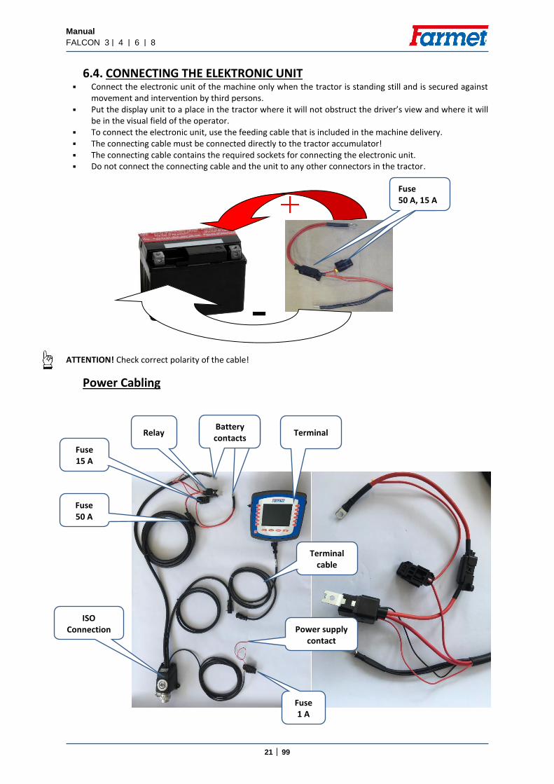
6.4. CONNECTING THE ELEKTRONIC UNIT Connect the electronic unit of the machine only when the tractor is standing still and is secured against
movement and intervention by third persons. Put the display unit to a place in the tractor where it will not obstruct the driver’s view and where it will
be in the visual field of the operator. To connect the electronic unit, use the feeding cable that is included in the machine delivery. The connecting cable must be connected directly to the tractor accumulator! The connecting cable contains the required sockets for connecting the electronic unit. Do not connect the connecting cable and the unit to any other connectors in the tractor.
ATTENTION! Check correct polarity of the cable!
Power Cabling
Pojis
Fuse 50 A, 15 A
Fuse 15 A
Fuse 50 A
Fuse 1 A
Terminal
Power supply contact
Relay
ISO Connection
Battery contacts
Terminal cable
Manual
FALCON 3 | 4 | 6 | 8
22 │ 99
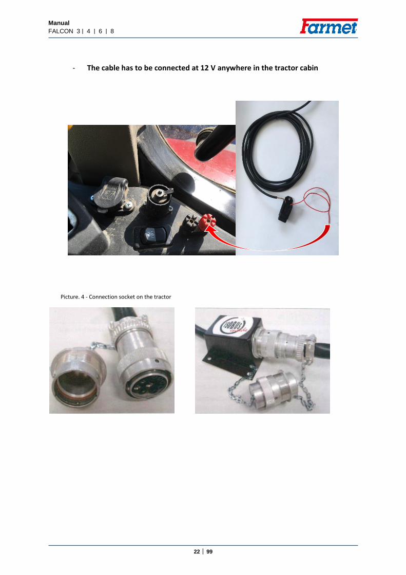
- The cable has to be connected at 12 V anywhere in the tractor cabin Picture. 4 - Connection socket on the tractor

Manual
FALCON 3 | 4 | 6 | 8
23 │ 99
6.5. CONNECTING THE HYDRAULIC MOTOR OF THE FAN
6.5.1 Description of the function
The hydraulic fan is powered directly from the tractor´s hydraulic system.
For proper operation, the hydraulic pump of the tractor must supply sufficient amount of oil so that the fan revolutions are not affected by decreased number of revolutions of the tractor engine or by another hydraulic circle being switched on.
The fan revolutions are set by regulating the oil flow rate. To change the fan revolutions, the tractor must be equipped with regulation of the oil flow rate.
Picture. 5 – Hydraulic drive
Tab. 5
Rotary hydraulic motor
Capacity (cm3/rev.) 8
Minimum revolutions of the small fan (rpm) 1000
Maximum revolutions of the small fan (rpm) 6000
Minimum revolutions of the big fan (rpm) 1000
Maximum revolutions of the big fan (rpm) 3000
Pressure oil - „P“
Minimum pressure in the “PRESSURE HOSE” (bar) 130
Maximum flow rate in the “PRESSURE HOSE” (l/min.)
40
Outlet - „T“ Maximum pressure in the “PRESSURE HOSE” (bar) 5
Hydraulic motor
Fan
Pressure hose
Free drain to the tractor tank must
be all time connected, even if fan is not working
Tank - „T“ (ISO 20)
Pressure - „P“ (ISO 12,5)
Measuring point of pressure
in the free drain hose

Manual
FALCON 3 | 4 | 6 | 8
24 │ 99
6.6. PROPER CONNECTION TO THE TRACTOR For proper connection, the following facts must be observed:
Outlet hose
- Do not connect the free drain hose to the tractor distributor! (pressure in the reverse branch would thus be increased)
- Large quick coupling on the free drain must not be changed for the smaller diameter.
- Oil returning through the outlet pipe must not be throttled anywhere
- Maximum allowed pressure value in the free drain hose is 5 bar, higher pressure pushes the shaft seal out, which causes damage to the hydraulic motor fan
Pressure hose
- Connect the pressure hose to the circuit giving priority to the oil supply
Picture. 6 – Position of quick couplings in the tractor
6.6.1 Connecting the free drain hose
Connect the outlet hose (outer ⌀ 27 mm) with the large quick coupling to the free drain to the tractor tank.
In case that there is no free drain to the tank attached to the tractor as standard, please contact the tractor manufacturer (dealer) for information regarding the possibilities of a free drain end piece.
Picture 7 – Outlet hose connection
Free drain to the tractor tank must
be all time connected, even if fan is not working
Free drain to the tank
Tractor distributor
Manual
FALCON 3 | 4 | 6 | 8
25 │ 99
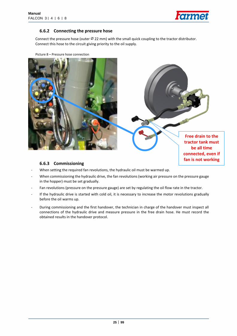
6.6.2 Connecting the pressure hose
Connect the pressure hose (outer ⌀ 22 mm) with the small quick coupling to the tractor distributor.
Connect this hose to the circuit giving priority to the oil supply.
Picture 8 – Pressure hose connection
6.6.3 Commissioning
- When setting the required fan revolutions, the hydraulic oil must be warmed up.
- When commissioning the hydraulic drive, the fan revolutions (working air pressure on the pressure gauge in the hopper) must be set gradually.
- Fan revolutions (pressure on the pressure gauge) are set by regulating the oil flow rate in the tractor.
- If the hydraulic drive is started with cold oil, it is necessary to increase the motor revolutions gradually before the oil warms up.
- During commissioning and the first handover, the technician in charge of the handover must inspect all connections of the hydraulic drive and measure pressure in the free drain hose. He must record the obtained results in the handover protocol.
Free drain to the tractor tank must
be all time connected, even if fan is not working

Manual
FALCON 3 | 4 | 6 | 8
26 │ 99
Picture. 9 - Diagram of the hydraulic drive of the fan
1. Hydraulic motor 2. Pressure hose 3. Outlet hose
4. Measuring point 5. Free drain to the tractor tank 6. Tractor distributor
Warning! Farmet a.s. is not liable for any damage of the hydraulic drive or the tractor caused by improper connection of the hydraulic drive.
7. ELECTRONIC SYSTEM OF THE MACHINE
General Instructions for Use:
- Install the feeding cable (included in the delivery) in the tractor system prior to the connection of the electronic system
- The cable must be connected directly to the tractor accumulator - The connection of the cable to the accumulator must be fixed and with a good contact – otherwise there
may be system failures and improper function - The cable must not be connected to any other connectors of the tractor! - Pay attention to proper poling (black - , red +) - The cable is equipped with two circuit fuses – 50A, 15A and 1A fuse for the terminal - Use only the delivered cable to connect the electronic system - The voltage in the accumulator must be within the range from 12 V to 14.4 V to ensure proper function
of the system - Secure the connecting cables between the machine and tractor against mechanical damage and against
heat stress from the hot parts of the tractor and hydraulic conduction - Turn on the display after you have connected the system to the power source - If an unusual situation occurs during the operation, disconnect the whole system from the power source
for a short time - Only connect and disconnect all the modules of the control system when the system is disconnected from
the power supply - Turn on the system after you have started the tractor motor (do not start the motor with the system on) - If the current fuse blows, first find the cause of the defect or seek professional service - Do not replace the current fuse with another item - Some parts of the system may heat up to the temperature of 50°C during operation. If the temperature
is higher, look for the cause or seek professional service - Protect the display from water and temperatures below -20°C and above +60°C - If you have to perform welding on the machine or the tractor, disconnect the unit from the power source
and disconnect the connecting cables
TRACTOR
SOWING MACHINE
5
3
1
4
2
6

Manual
FALCON 3 | 4 | 6 | 8
27 │ 99
7.1. TURNING THE SOWING ON AND OFF Turning the sowing on and off is controlled by two sensors. The system is designed so that the sowing turns on at the beginning of recessing. Before the seeds go through the whole system of the pneumatic distribution, the machine has already recessed and the delay in the launch of sowing at the beginning of the patch is thus minimized. The sowing is turned off at the beginning of digging out.
TURNING ON THE SOWING
Turning on is controlled by an aerial sensor. The aerial sensor is set to turn on at the beginning of recessing. The sensitivity of the switching depends on the position of the sensor set between the axle frame and the main frame of the machine. It can be adjusted by loosening the screws (see the picture 10) and changing the position of the sensor towards the holder. Furthermore, the sensor turns on the control of the machine functions.
TURNING OFF THE SOWING
Turning the sowing off (the electric motors of the seed feeders) is controlled by a pressure sensor located in the hydraulic circuit of the axle lifting. The sensitivity of this sensor is set to the pressure of 10 MPa. When the machine is digging out, the oil pressure is led to the hydraulic distributor and when the set value is reached, the switch turns on and the motors of the seed feeders turn off.
Therefore, move the lever for the hydraulic control to the FLOATING POSITION after the machine has been recessed!!!
The sensitivity of the pressure and aerial sensors is standardly set by the producer. Only a professional service may change the sett.
Picture 10 – Aerial sensor Picture 11 - Pressure sensor
Radar
The radar provides a very exact measurement of the travel sped which is important for exact batch of seeds. Do not stay or move in the working area of the radar.
Location of the
pressure sensor
Setting the position
against the frame
Antenna sensor

Manual
FALCON 3 | 4 | 6 | 8
28 │ 99
7.2. DESCRIPTION OF MACHINE CONTROL BY MÜLLER ELECTRONICS Falcon sowing machines are equipped with the Müller electronic system. The following chapters briefly
and clearly describe the basic control and description of the electronic system.
7.3. DESCRIPTION OF THE BASIC DISPLAY The basic display of the terminal is shown in the picture below the text. The basic display provides access
to all functions that are required for the work in the field. Also, the basic display shows all important data, such as speed of the machinery, ventilator revolutions, seed quantity, creation of rail lines, and the position of the rear sowing section.
Picture. 12 – basic display
Hopper level
Fan speed Travel speed
Trip counting and tramline marking
Switching ON/OFF the application
Seed rate correction
Machine hydraulics
control
Settings
Information
Tramline setting
Sowing function
Here are visible activated options, example markers
Fan speed Travel speed
Trip couting and tramline marking
Symbol showing the position of the
rear sowing section (recessed)
Engine 1 (seeder)
Engine 2 (seeder)
Engine 3 (seeder)

Manual
FALCON 3 | 4 | 6 | 8
29 │ 99
7.4. CONTROLLING HYDRAULICS Procedure for unfolding and folding the machine
Open the blue ball valve located on the machine drawbar (A) LEAVE OPEN FOR WORK
Press the key for controlling hydraulics (B)
Then press the key for unfolding/folding (C) and unfold the machine
Confirm the task after the machine has unfolded (D)
Picture 13 – Procedure for folding/unfolding the machine
Controlling the rear sowing section – controlled from the tractor using the blue hydraulic circuit when the application is activated (also possible to control when the display unit is off). Then in combination with markers.
Controlling the front sowing section – controlled from the tractor using the yellow hydraulic circuit when the application is activated. For transport, it is required to close the ball valve located on the pole of the machine to prevent undesirable movement of the front section during transport.
A
D C B

Manual
FALCON 3 | 4 | 6 | 8
30 │ 99
7.4.1 Controlling markers
Markers are controlled by pressing the key for markers control as shown in the picture below. On the following screen choose which marker or function you want to activate. If no marker is selected before the run, the machine will work without them.
Picture 14 – Controlling markers
Picture 15 – Description of markers control
Controlling of markers
Function marsh
Turn right marker ON
Turn marker automatics ON
Turn left marker ON
Turn both markers OFF
Obstacle function
Turn both markers ON
Displaying the activated marker
Selection of automated
markers

Manual
FALCON 3 | 4 | 6 | 8
31 │ 99
Obstacle function – used for avoiding obstacles. When this icon is activated, only the activated marker is lifted when the hydraulic circuit is pressed but the machine remains recessed and seeding. The activated element is always displayed in the right bottom corner of the display unit. Marsh function – if it is necessary to drive through wet spots (marshes) during seeding or when the machine accidentally ends up in a marsh, then this function can be activated by pressing the corresponding hydraulic circuit that lifts the sowing section but the machine continues sowing. This increases the passage ability of the machine through wet spots.
Picture 16 – Description of functions
Activating the marsh function
This is where activated functions are displayed, for information only

Manual
FALCON 3 | 4 | 6 | 8
32 │ 99
7.5. RAIL LINES SETTING SYSTEM The Müller electronic system allows various rail lines setting.
For basic rail lines setting, you need to know where and how many rail flaps are installed and used on the machine. Graphic illustration follows.
A)
Two rail flaps on both sides of the machine
Our most frequently used solution
This layout of rail flaps always corresponds with an odd number of passes of the seed drill per width of the sprayer
It is also possible to set the rhythm of rail lines for even number of passes of the machine, but that requires the execution of a “zero pass”
B)
Two rail line flaps on one side of the machine (on the right or on the left)
The location of the flaps on the right or on the left depends on which side of the field seeding starts on
C)
One rail line flap on one side of the machine

Manual
FALCON 3 | 4 | 6 | 8
33 │ 99
7.5.1 Setting rail lines rhythm
This specific setting of the rail lines is accessed via the first screen where we press the button of the relevant rail lines icon. Then press the button for rail lines setting (a symbol of rail lines with lower-case letter “n” in the right bottom corner). There you select the required configuration of the rail lines rhythm; the configuration depends on the versions (A, B, C) described above.
Line No. Number of the rail line (number of passes of the machine per width of the sprayer)
Length Number of passes that determines the rail lines rhythm repetition
Left, Right Determines the pass during which a rail line is created (left, right)
Individual Setting Here you can choose your own settings
Individual steps for setting the correct rail lines rhythm
1. We know the width of the machine 2. We know the width of the sprayer 3. We know the number of rail flaps on the machine and we know exactly where they are located (which
side, number…) 4. We have to do a simple calculation
Structural width of the sprayer: Structural width of the machine 5. Select the rail lines rhythm on the appropriate screen based on the facts above

Manual
FALCON 3 | 4 | 6 | 8
34 │ 99
Version A) Rail lines are formed during one pass of the seed drill
a.
Possible flap positions
Calculation result Line No. Resulting rhythm
Left flaps Right flaps
3 3 3 2 2
5 5 5 3 3
7 7 7 4 4
9 9 9 5 5
11 11 11 6 6
Example: The structural width of the sprayer is 30 m, the structural width of the machine is 6 m. Procedure: 30:6=5 → Resulting rhythm – green line in the chart
Manual
FALCON 3 | 4 | 6 | 8
35 │ 99
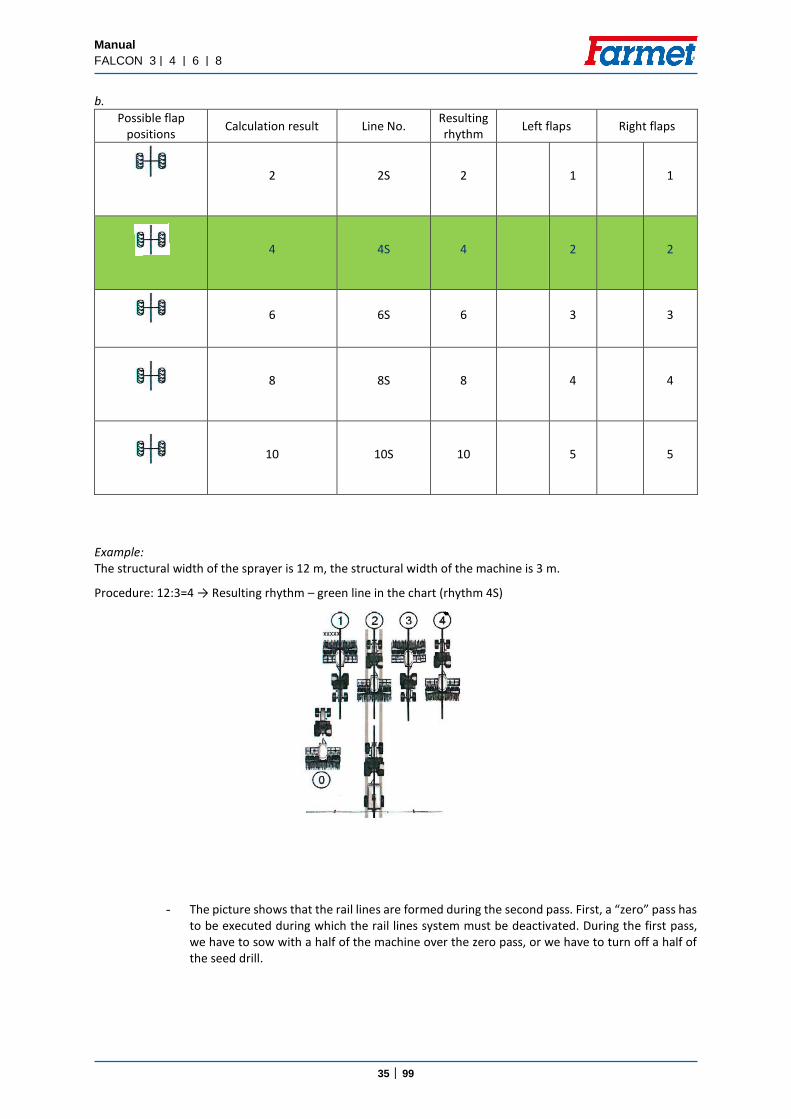
b.
Possible flap positions
Calculation result Line No. Resulting rhythm
Left flaps Right flaps
2 2S 2 1 1
4 4S 4 2 2
6 6S 6 3 3
8 8S 8 4 4
10 10S 10 5 5
Example: The structural width of the sprayer is 12 m, the structural width of the machine is 3 m.
Procedure: 12:3=4 → Resulting rhythm – green line in the chart (rhythm 4S)
- The picture shows that the rail lines are formed during the second pass. First, a “zero” pass has to be executed during which the rail lines system must be deactivated. During the first pass, we have to sow with a half of the machine over the zero pass, or we have to turn off a half of the seed drill.

Manual
FALCON 3 | 4 | 6 | 8
36 │ 99
Version B) Rail lines are formed during one pass of the seed drill
Sowing starts on the left side of the field
Possible flap positions Calculation result Line No.
Resulting rhythm
Left flaps Right flaps
2 999 2 1
4 999 4 2
6 999 6 3
Example: The structural width of the sprayer is 24 m, the structural width of the machine is 6 m. Procedure: 24:6=4 → Resulting rhythm – green line in the chart
The picture shows that the rail lines are formed during the second pass
If the rail flaps are located on the other side of the seed bar, the procedure will be the same but sowing starts on the right side of the field and thus rail lines will be formed on the right side of the seed drill.

Manual
FALCON 3 | 4 | 6 | 8
37 │ 99
Version C) Rail lines are formed during two passes of the seed drill
If sowing starts on the left side of the field
Possible flap positions
Calculation result Line No. Resulting rhythm
Left flaps Right flaps
2 999 2 1 2
4 999 4 2 3
6 999 6 3 4
8 999 8 4 5
10 999 10 5 6
12 999 12 6 7
14 999 14 7 8
Example: The structural width of the sprayer is 12 m, the structural width of the machine is 3 m. Procedure: 12:3=4 → Resulting rhythm – green line in the chart
The picture shows that rail lines are formed during the second and third pass of the seed drill.
If the rail flaps are located on the other side of the seed bar, the procedure will be the same but sowing starts on the right side of the field and thus rail lines will be formed on the right side of the seed drill.

Manual
FALCON 3 | 4 | 6 | 8
38 │ 99
7.5.2 Our most frequently used rail lines setting
The actual setting of rail lines is performed on the rail lines setting screen. For better orientation and understanding of the rail lines setting, we provide both graphic and chart illustration. The system of setting the rhythm of the rail lines is shown both in the graphic and chart illustration.
Width of the machine (m)
Width of the sprayer (m)
Program Line No.
Number of passes per machine
width (length
On the left On the right
3 15 5 5 3 3
3 21 7 7 4 4
3 27 9 9 5 5
4 20 5 5 3 3
4 28 7 7 4 4
4 36 9 9 5 5
6 18 3 3 2 2
6 30 5 5 3 3
6 42 7 7 4 4
8 24 3 3 2 2
8 40 5 5 3 3
Width of the seed drill 6 m Width of the sprayer 42 m
Width of the seed drill 3 m Width of the sprayer 15 m
Width of the seed drill 4 m Width of the sprayer 36 m
Setting marker flaps (left, right)
How many times a track is created

Manual
FALCON 3 | 4 | 6 | 8
39 │ 99
7.5.3 Setting rail lines Picture 18 – Setting rail lines
Picture 19 - Setting the rhythm of rail lines in the display unit
Adding passes
Deducting passes
Blocking rail line passes
Setting rail lines
This is where you enter (using the pivoting cursor)
selected values
This is where you enter
where the rail line flaps are
located

Manual
FALCON 3 | 4 | 6 | 8
40 │ 99
7.6. REFERENCE DATA Picture 20 – Reference data
7.6.1 Creating an order
Useful for field descriptions and customer service.
Area sown
Area quantity
Deleting values
Total value Service hours
Total time
Total distance
Total area
Area output
Area output
Order creation
Number of task
Order name
Product name
Stopping the order
Total area Total amount

Manual
FALCON 3 | 4 | 6 | 8
41 │ 99
7.6.2 Levels of seeds in the hopper
There is a level sensor in the hopper that shows the remaining amount of seeds. The sensor can be adjusted by height according to the type of seeds or as required by the operator. When the amount drops below the level, the sensor illuminates a red symbol on the display (top right corner). This signalization is accompanied with a warning message. Activation/deactivation of sowing or fertilization – this button is used for activating or deactivating sowing or fertilization: the button stops the appropriate motor driving the seeding mechanism (also, sensors in the hopper are deactivated).
Picture 21 – Activation/deactivation of sowing or fertilization
7.7. SETTING PASSAGE SENSORS
DICKEY JOHN SYSTEM – The sensitivity setting is fully automated
Activation/deactivation of sowing or fertilization
Change of hopper
Signalling low seed level in the hopper

Manual
FALCON 3 | 4 | 6 | 8
42 │ 99
AGTRON SYSTEM
With regard to the passage sensors, the sensitivity of the setting of the individual sensors is important.
Practice shows that cereals should be set at 6 and fine seeds, such as rape, should be set at 3. If none of the sowing hoses is clogged, the status of sensors is not displayed anywhere. At the moment when
one of the hoses gets clogged, an error message is displayed – a chart appears on the display showing which sensor is blocked (in which row).
Picture 22 – Setting the sowing sensors
Setting the sensors of
seed passage
Diagnostics

Manual
FALCON 3 | 4 | 6 | 8
43 │ 99
Control value of sensors – at 10 km/h
ZJ value Type of seeds Seed quantity per time
0 System off (no report)
1 RAPE, MUSTARD 1 seed/16s
2 RAPE, MUSTARD 1 seed/8s
3 RAPE, MUSTARD 1 seed/2s
4 WHEAT, RYE, BARLEY 1 seed/s
5 WHEAT, RYE, BARLEY, OATS 2 seed/s
6 WHEAT, RYE, BARLEY, OATS 5 seed/s
7 OATS 10 seed/s
8 OATS 20 seed/s
9 100 seed/s
10 1000 seed/s If the defined number of seeds does not pass through during the given time, the system reports a low passage of seeds, so this is not sensitivity as such but a control parameter of the seed passage. Picture 23 – Setting sensor sensitivity
Increased sensitivity
Decreased sensitivity
Diagnostics of sowing sensors

Manual
FALCON 3 | 4 | 6 | 8
44 │ 99
7.7.1 Seeding sensors diagnostics
This screen is used for checking the passability of the individual sowing hoses. When there are red crosses in all rows, seeds do not pass through the sensor. The passage of seeds is signalled by green ticks, i.e. when there are green ticks in all rows, all sensors are working correctly – the hoses are passable and the seeds pass through them.
The passability of seeds can also be checked during driving in the sensor diagnostics. If any of the hoses gets clogged, the passage sensor registers it and a signal in the form of a chart appears on the main screen showing which hose is blocked.
Displaying sensor diagnostics – red crosses → seeds do not pass
– green ticks → seeds pass
Picture 24 – Sensor diagnostics
7.7.2 Switching off the seed flow system sensor
OFF/ON: when the seeding application is OFF---setting---page 3/3---Agtron/NO
Sensors 1 - 10 Sensor number 1
Sensor number 5
Sensor number 10
Error 0
Sensor 0
Push it
Manual
FALCON 3 | 4 | 6 | 8
45 │ 99
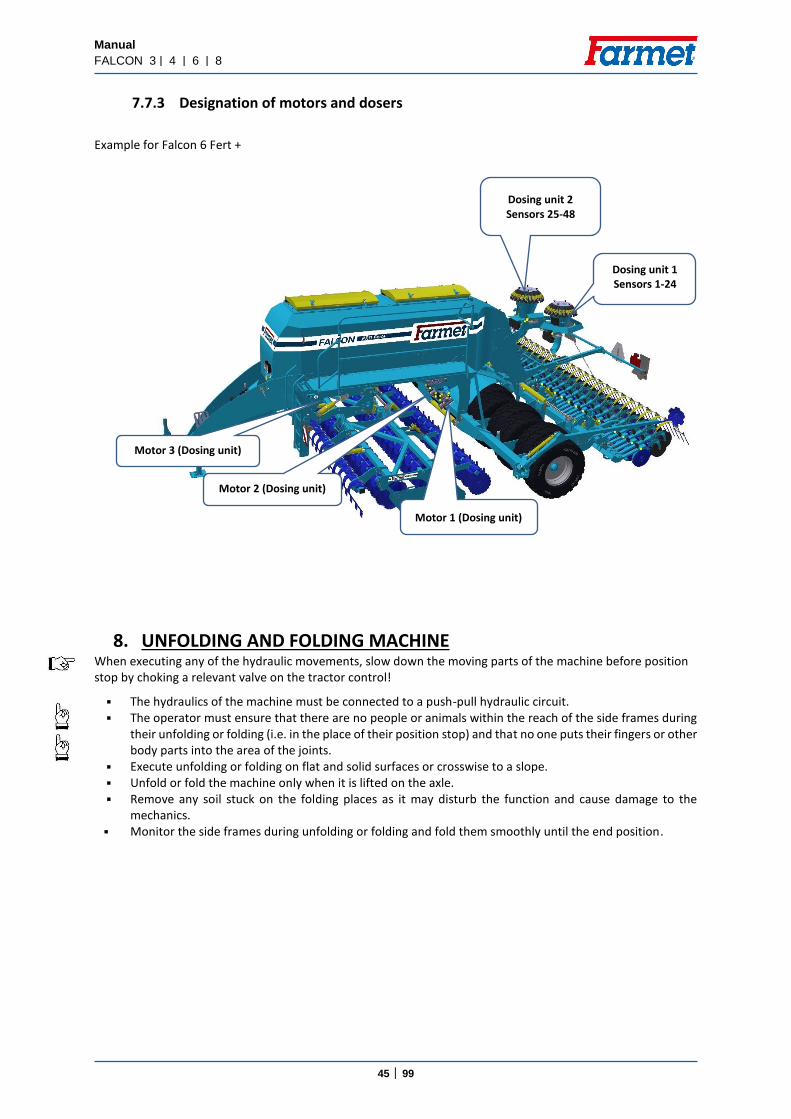
7.7.3 Designation of motors and dosers
Example for Falcon 6 Fert +
8. UNFOLDING AND FOLDING MACHINE When executing any of the hydraulic movements, slow down the moving parts of the machine before position stop by choking a relevant valve on the tractor control!
The hydraulics of the machine must be connected to a push-pull hydraulic circuit. The operator must ensure that there are no people or animals within the reach of the side frames during
their unfolding or folding (i.e. in the place of their position stop) and that no one puts their fingers or other body parts into the area of the joints.
Execute unfolding or folding on flat and solid surfaces or crosswise to a slope. Unfold or fold the machine only when it is lifted on the axle. Remove any soil stuck on the folding places as it may disturb the function and cause damage to the
mechanics. Monitor the side frames during unfolding or folding and fold them smoothly until the end position.
Motor 3 (Dosing unit)
Motor 1 (Dosing unit)
Motor 2 (Dosing unit)
Dosing unit 1 Sensors 1-24
Dosing unit 2 Sensors 25-48

Manual
FALCON 3 | 4 | 6 | 8
46 │ 99
8.1. UNFOLDING THE MACHINE
1. Prior to unfolding, it is necessary to unblock the mechanical protection of the side frames on the front preparatory section. This protection is mechanical (pins in the front joints of the folding mechanism, one on each side) or hydraulic.
mechanical protection hydraulic protection
2. Open the blue ball valve (MUST STAY OPEN FOR WORK)
3. Press the key for machine hydraulics control (A) on the display unit screen, then press the key for unfolding/folding (B).
B A
Manual
FALCON 3 | 4 | 6 | 8
47 │ 99
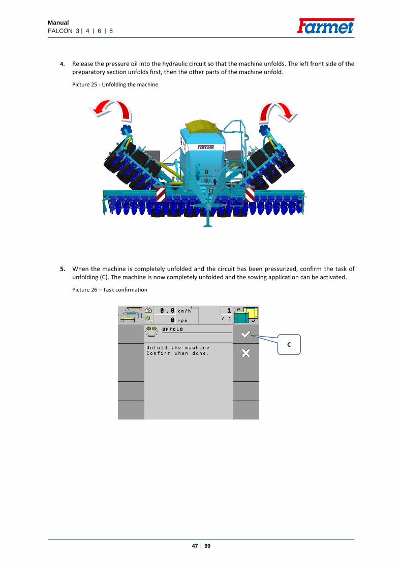
4. Release the pressure oil into the hydraulic circuit so that the machine unfolds. The left front side of the preparatory section unfolds first, then the other parts of the machine unfold.
Picture 25 - Unfolding the machine
5. When the machine is completely unfolded and the circuit has been pressurized, confirm the task of unfolding (C). The machine is now completely unfolded and the sowing application can be activated.
Picture 26 – Task confirmation
C

Manual
FALCON 3 | 4 | 6 | 8
48 │ 99
8.2. FOLDING THE MACHINE
When folding the machine, progress in a reversed way:
1. Lift the machine fully and close the valve of the front preparatory section (see Picture 30).
2. Turn on the folding/unfolding function on the display unit, see Picture 27.
Picture 27 - Unfolding/folding on
3. Release the pressure oil so that the machine folds into the transport position.
Picture 28 – Folding the machine
A

Manual
FALCON 3 | 4 | 6 | 8
49 │ 99
4. Then, the task of folding the machine must be confirmed (C)
Picture 29 – Task confirmation
5. Close the blue ball valve.
Picture 30 – Closing the folding valve
6. Secure the front section for transport, either mechanically or hydraulically (according to the equipment)
Picture 31 – Securing the front section
C

Manual
FALCON 3 | 4 | 6 | 8
50 │ 99
9. LOWERING AND LIFTING 1. Open the tap of the ball valve of the piston-rods for lifting the front preparatory section.
Picture 32 - Ball valve, front section, position OFF
10. FILLING UP THE SEED/FERTILIZER CONTAINER
When filling up the container, always observe safety regulations and instructions. The machine must be fully unfolded and must be resting on the working bodies on the ground. Only fill up the container on a solid and flat surface and when the machine is standing still. Use the access ladder for access to the service platform. Remove and store the canvas. Remove the central brackets of the canvas. Fill up the hopper with the required type and volume of seeds/fertilizer. Return the central brace rods back and cover the hopper with the protecting canvas The platform is only intended for the operator for filling up the container. It is strictly forbidden to use the platform during driving and operation of the machine. The bearing capacity of the platform is limited to 3 persons or 280kg at the most! Be extra careful when moving on the platform. It is strictly forbidden to transport persons or cargo on the machine!
Picture 33 – Filling up the container
Fertilizer
Seed
Access ladder
Operating bridge

Manual
FALCON 3 | 4 | 6 | 8
51 │ 99
11. SETTING THE FILLED SEEDS/FERTILIZER
(NOT REQUIRED FOR WORK)
1. Select the icon of filling the hopper in the machine setting on page 2/3.
2. Write down the weight that you poured into the hopper (use the rotary knob on the side of the terminal).
Filled to maximum
Empty hopper
Current hopper status
How much will be added to the hopper
Current hopper status
Current hopper status in percentage

Manual
FALCON 3 | 4 | 6 | 8
52 │ 99
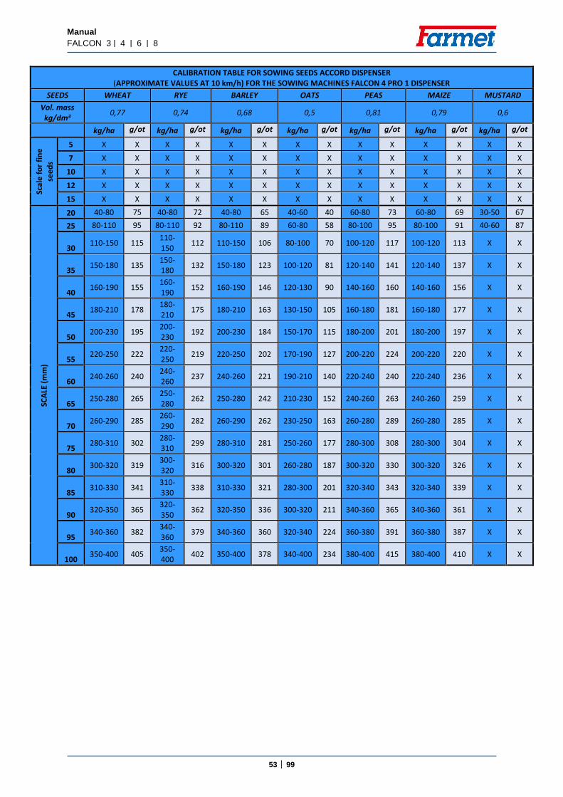
12. SETTING OF THE SOWING BATCH
Accord Dispenser
The first step is to set the turnstile according to the calibration table.
CALIBRATION TABLE FOR SOWING SEEDS ACCORD DISPENSER
(APPROXIMATE VALUES AT 10 km/h) FOR THE SOWING MACHINES FALCON 3 PRO 1 DISPENSER
SEEDS WHEAT RYE BARLEY OATS PEAS MAIZE MUSTARD
Vol. mass kg/dm3
0,77 0,74 0,68 0,5 0,81 0,79 0,6
kg/ha g/ot kg/ha g/ot kg/ha g/ot kg/ha g/ot kg/ha g/ot kg/ha g/ot kg/ha g/ot
Scal
e f
or
fin
e s
ee
ds
5 X X X X X X X X X X X X X X
7 X X X X X X X X X X X X X X
10 X X X X X X X X X X X X X X
12 X X X X X X X X X X X X X X
15 X X X X X X X X X X X X X X
SCA
LE (
mm
)
20 40-80 75 40-80 72 40-80 65 40-60 40 60-80 73 60-80 69 30-50 67
25 80-110 95 80-110 92 80-110 89 60-80 58 80-100 95 80-100 91 40-60 87
30 110-150 115 110-150 112 110-150 106 80-100 70 100-120 117 100-120 113 X X
35 150-180 135 150-180 132 150-180 123 100-120 81 120-140 141 120-140 137 X X
40 160-190 155 160-190 152 160-190 146 120-130 90 140-160 160 140-160 156 X X
45 180-210 178 180-210 175 180-210 163 130-150 105 160-180 181 160-180 177 X X
50 200-230 195 200-230 192 200-230 184 150-170 115 180-200 201 180-200 197 X X
55 220-250 222 220-250 219 220-250 202 170-190 127 200-220 224 200-220 220 X X
60 240-260 240 240-260 237 240-260 221 190-210 140 220-240 240 220-240 236 X X
65 250-280 265 250-280 262 250-280 242 210-230 152 240-260 263 240-260 259 X X
70 260-290 285 260-290 282 260-290 262 230-250 163 260-280 289 260-280 285 X X
75 280-310 302 280-310 299 280-310 281 250-260 177 280-300 308 280-300 304 X X
80 300-320 319 300-320 316 300-320 301 260-280 187 300-320 330 300-320 326 X X
85 310-330 341 310-330 338 310-330 321 280-300 201 320-340 343 320-340 339 X X
90 320-350 365 320-350 362 320-350 336 300-320 211 340-360 365 340-360 361 X X
95 340-360 382 340-360 379 340-360 360 320-340 224 360-380 391 360-380 387 X X
100 350-400 405 350-400 402 350-400 378 340-400 234 380-400 415 380-400 410 X X
Manual
FALCON 3 | 4 | 6 | 8
53 │ 99
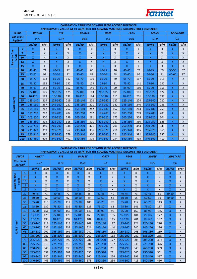
CALIBRATION TABLE FOR SOWING SEEDS ACCORD DISPENSER (APPROXIMATE VALUES AT 10 km/h) FOR THE SOWING MACHINES FALCON 4 PRO 1 DISPENSER
SEEDS WHEAT RYE BARLEY OATS PEAS MAIZE MUSTARD
Vol. mass kg/dm3
0,77 0,74 0,68 0,5 0,81 0,79 0,6
kg/ha g/ot kg/ha g/ot kg/ha g/ot kg/ha g/ot kg/ha g/ot kg/ha g/ot kg/ha g/ot
Scal
e f
or
fin
e
see
ds
5 X X X X X X X X X X X X X X
7 X X X X X X X X X X X X X X
10 X X X X X X X X X X X X X X
12 X X X X X X X X X X X X X X
15 X X X X X X X X X X X X X X
SCA
LE (
mm
)
20 40-80 75 40-80 72 40-80 65 40-60 40 60-80 73 60-80 69 30-50 67
25 80-110 95 80-110 92 80-110 89 60-80 58 80-100 95 80-100 91 40-60 87
30 110-150 115
110-150
112 110-150 106 80-100 70 100-120 117 100-120 113 X X
35 150-180 135
150-180
132 150-180 123 100-120 81 120-140 141 120-140 137 X X
40 160-190 155
160-190
152 160-190 146 120-130 90 140-160 160 140-160 156 X X
45 180-210 178
180-210
175 180-210 163 130-150 105 160-180 181 160-180 177 X X
50 200-230 195
200-230
192 200-230 184 150-170 115 180-200 201 180-200 197 X X
55 220-250 222
220-250
219 220-250 202 170-190 127 200-220 224 200-220 220 X X
60 240-260 240
240-260
237 240-260 221 190-210 140 220-240 240 220-240 236 X X
65 250-280 265
250-280
262 250-280 242 210-230 152 240-260 263 240-260 259 X X
70 260-290 285
260-290
282 260-290 262 230-250 163 260-280 289 260-280 285 X X
75 280-310 302
280-310
299 280-310 281 250-260 177 280-300 308 280-300 304 X X
80 300-320 319
300-320
316 300-320 301 260-280 187 300-320 330 300-320 326 X X
85 310-330 341
310-330
338 310-330 321 280-300 201 320-340 343 320-340 339 X X
90 320-350 365
320-350
362 320-350 336 300-320 211 340-360 365 340-360 361 X X
95 340-360 382
340-360
379 340-360 360 320-340 224 360-380 391 360-380 387 X X
100 350-400 405
350-400
402 350-400 378 340-400 234 380-400 415 380-400 410 X X
Manual
FALCON 3 | 4 | 6 | 8
54 │ 99
CALIBRATION TABLE FOR SOWING SEEDS ACCORD DISPENSER
(APPROXIMATE VALUES AT 10 km/h) FOR THE SOWING MACHINES FALCON 8 PRO 1 DISPENSER
SEEDS WHEAT RYE BARLEY OATS PEAS MAIZE MUSTARD
Vol. mass kg/dm3
0,77 0,74 0,68 0,5 0,81 0,79 0,6
kg/ha g/ot kg/ha g/ot kg/ha g/ot kg/ha g/ot kg/ha g/ot kg/ha g/ot kg/ha g/ot
Scal
e f
or
fin
e
see
ds
5 X X X X X X X X X X X X X X
7 X X X X X X X X X X X X X X
10 X X X X X X X X X X X X X X
12 X X X X X X X X X X X X X X
15 X X X X X X X X X X X X X X
SCA
LE (
mm
)
20 40-45 71 40-45 72 40-45 65 40-45 40 40-45 73 40-45 69 30-50 X
25 50-60 92 50-60 92 50-60 89 50-60 58 50-60 95 50-60 91 40-60 X
30 65-70 113 65-70 112 65-70 106 65-70 70 65-70 117 65-70 113 X X
35 75-80 132 75-80 132 75-80 123 75-80 81 75-80 141 75-80 137 X X
40 85-90 151 85-90 152 85-90 146 85-90 90 85-90 160 85-90 156 X X
45 95-105 175 95-105 175 95-105 163 95-105 105 95-105 181 95-105 177 X X
50 10-120 193 10-120 192 10-120 184 10-120 115 10-120 201 10-120 197 X X
55 125-140 219 125-140 219 125-140 202 125-140 127 125-140 224 125-140 220 X X
60 145-160 237 145-160 237 145-160 221 145-160 140 145-160 240 145-160 236 X X
65 165-180 262 165-180 262 165-180 242 165-180 152 165-180 263 165-180 259 X X
70 185-200 282 185-200 282 185-200 262 185-200 163 185-200 289 185-200 285 X X
75 205-220 300 205-220 299 205-220 281 205-220 177 205-220 308 205-220 304 X X
80 225-250 315 225-250 316 225-250 301 225-250 187 225-250 330 225-250 326 X X
85 260-290 340 260-290 338 260-290 321 260-290 201 260-290 343 260-290 339 X X
90 295-320 359 295-320 362 295-320 336 295-320 211 295-320 365 295-320 361 X X
95 325-340 380 325-340 379 325-340 360 325-340 224 325-340 391 325-340 387 X X
100 340-360 405 340-360 402 340-360 378 340-360 234 340-360 415 340-360 410 X X
CALIBRATION TABLE FOR SOWING SEEDS ACCORD DISPENSER (APPROXIMATE VALUES AT 10 km/h) FOR THE SOWING MACHINES FALCON 6 PRO 1 DISPENSER
SEEDS WHEAT RYE BARLEY OATS PEAS MAIZE MUSTARD
Vol. mass kg/dm3
0,77 0,74 0,68 0,5 0,81 0,79 0,6
kg/ha g/ot kg/ha g/ot kg/ha g/ot kg/ha g/ot kg/ha g/ot kg/ha g/ot kg/ha g/ot
Scal
e f
or
fin
e
see
ds
5 X X X X X X X X X X X X X X
7 X X X X X X X X X X X X X X
10 X X X X X X X X X X X X X X
12 X X X X X X X X X X X X X X
15 X X X X X X X X X X X X X X
SCA
LE (
mm
)
20 40-45 71 40-45 72 40-45 65 40-45 40 40-45 73 40-45 69 30-50 67
25 50-60 92 50-60 92 50-60 89 50-60 58 50-60 95 50-60 91 40-60 87
30 65-70 113 65-70 112 65-70 106 65-70 70 65-70 117 65-70 113 X X
35 75-80 132 75-80 132 75-80 123 75-80 81 75-80 141 75-80 137 X X
40 85-90 151 85-90 152 85-90 146 85-90 90 85-90 160 85-90 156 X X
45 95-105 175 95-105 175 95-105 163 95-105 105 95-105 181 95-105 177 X X
50 10-120 193 10-120 192 10-120 184 10-120 115 10-120 201 10-120 197 X X
55 125-140 219 125-140 219 125-140 202 125-140 127 125-140 224 125-140 220 X X
60 145-160 237 145-160 237 145-160 221 145-160 140 145-160 240 145-160 236 X X
65 165-180 262 165-180 262 165-180 242 165-180 152 165-180 263 165-180 259 X X
70 185-200 282 185-200 282 185-200 262 185-200 163 185-200 289 185-200 285 X X
75 205-220 300 205-220 299 205-220 281 205-220 177 205-220 308 205-220 304 X X
80 225-250 315 225-250 316 225-250 301 225-250 187 225-250 330 225-250 326 X X
85 260-290 340 260-290 338 260-290 321 260-290 201 260-290 343 260-290 339 X X
90 295-320 359 295-320 362 295-320 336 295-320 211 295-320 365 295-320 361 X X
95 325-340 380 325-340 379 325-340 360 325-340 224 325-340 391 325-340 387 X X
100 340-360 405 340-360 402 340-360 378 340-360 234 340-360 415 340-360 410 X X

Manual
FALCON 3 | 4 | 6 | 8
55 │ 99
CALIBRATION TABLE FOR SOWING SEEDS ACCORD DISPENSER (APPROXIMATE VALUES AT 10 km/h) FOR THE SOWING MACHINES FALCON 9 PRO 1 DISPENSER
SEEDS WHEAT RYE BARLEY OATS PEAS MAIZE MUSTARD
Vol. mass kg/dm3
0,77 0,74 0,68 0,5 0,81 0,79 0,6
kg/ha g/ot kg/ha g/ot kg/ha g/ot kg/ha g/ot kg/ha g/ot kg/ha g/ot kg/ha g/ot
Scal
e f
or
fin
e
see
ds
5 X X X X X X X X X X X X X X
7 X X X X X X X X X X X X X X
10 X X X X X X X X X X X X X X
12 X X X X X X X X X X X X X X
15 X X X X X X X X X X X X X X
SCA
LE (
mm
)
20 40-45 71 40-45 72 40-45 65 40-45 40 40-45 73 40-45 69 30-50 X
25 50-60 92 50-60 92 50-60 89 50-60 58 50-60 95 50-60 91 40-60 X
30 65-70 113 65-70 112 65-70 106 65-70 70 65-70 117 65-70 113 X X
35 75-80 132 75-80 132 75-80 123 75-80 81 75-80 141 75-80 137 X X
40 85-90 151 85-90 152 85-90 146 85-90 90 85-90 160 85-90 156 X X
45 95-105 175 95-105 175 95-105 163 95-105 105 95-105 181 95-105 177 X X
50 10-120 193 10-120 192 10-120 184 10-120 115 10-120 201 10-120 197 X X
55 125-140 219 125-140 219 125-140 202 125-140 127 125-140 224 125-140 220 X X
60 145-160 237 145-160 237 145-160 221 145-160 140 145-160 240 145-160 236 X X
65 165-180 262 165-180 262 165-180 242 165-180 152 165-180 263 165-180 259 X X
70 185-200 282 185-200 282 185-200 262 185-200 163 185-200 289 185-200 285 X X
75 205-220 300 205-220 299 205-220 281 205-220 177 205-220 308 205-220 304 X X
80 225-250 315 225-250 316 225-250 301 225-250 187 225-250 330 225-250 326 X X
85 260-290 340 260-290 338 260-290 321 260-290 201 260-290 343 260-290 339 X X
90 295-320 359 295-320 362 295-320 336 295-320 211 295-320 365 295-320 361 X X
95 325-340 380 325-340 379 325-340 360 325-340 224 325-340 391 325-340 387 X X
100 340-360 405 340-360 402 340-360 378 340-360 234 340-360 415 340-360 410 X X
CALIBRATION TABLE FOR FINE SEEDS (APPROXIMATE VALUES AT 10 km/h) FOR THE SOWING MACHINES FALCON PRO 1 DISPENSER
SEEDS RAPE ROTKLLE GRASS PHACELIA POPPY
Vol. mass kg/dm3
0,65 0,8 0,36 0,22 0,4
kg/ha g/ot kg/ha g/ot kg/ha g/ot kg/ha g/ot kg/ha g/ot
SCA
LE (
mm
)
4 X X X X X X X X 0,5 – 1,5 2
5 1,5 - 2 2 5 3 X X X X 1,5 - 2 3
6 2,5 3 6 4 X X X X 2 4
7 3 3 7 5 X X X X 2,5 - 3 5
8 3,5 4 9 6 X X X X X X
9 4 4 12 7 4 4 X X X X
10 4,5 5 15 9 6 5 5 5 X X
11 5 5 20 11 7 6 6 5 X X
12 5,5 6 22 13 10 7 7 6 X X
13 6 6 25 15 14 8 8 7 X X
15 X X X X X X 10 7 X X
17 X X X X X X 11-15 8 X X
20 X X X X X X 16-20 10 X X

Manual
FALCON 3 | 4 | 6 | 8
56 │ 99
Attention!!!
When sowing fine seeds, use the fine roller (micro sowing) and pull out the red wheel. Picture 34 – Setting the feeder
Farmet Dispenser - Roller replacement system
1 2 1 2 1 2 1 2 1 2
5 - 15 km/h kg/ha min 0,9 1,8 0,7 1,4 0,5 0,9 0,3 0,7 0,3 0,6
5 - 15 km/h kg/ha max 3,6 7,2 2,7 5,4 1,8 3,6 1,4 2,7 1,2 2,4
5 - 15 km/h kg/ha min 1,8 3,6 1,4 2,7 0,9 1,8 0,7 1,4 0,6 1,2
5 - 15 km/h kg/ha max 7,2 14,4 5,4 10,8 3,6 7,2 2,7 5,4 2,4 4,8
5 - 15 km/h kg/ha min 6 12 4,5 9 3 6 2,3 4,5 2 4
5 - 15 km/h kg/ha max 24 48 18 36 12 24 9 18 8 16
5 - 15 km/h kg/ha min 13 26 10 20 7 13 5 10 4 9
5 - 15 km/h kg/ha max 50 100 38 75 25 50 19 38 17 33
5 - 15 km/h kg/ha min 30 60 23 45 15 30 11 23 10 20
5 - 15 km/h kg/ha max 120 240 90 180 60 120 45 90 40 80
5 - 15 km/h kg/ha min 75 150 56 113 38 75 28 56 25 50
5 - 15 km/h kg/ha max 300 600 225 450 150 300 113 225 100 200
5 - 15 km/h kg/ha min 150 300 113 225 75 150 56 113 50 100
5 - 15 km/h kg/ha max 600 1200 450 900 300 600 225 450 200 400
9 mCrop
Number of dispensers
V3,5Rape, mustard, grass
seed, etc.
Working width 3 m 4 m 6 m 8 m
V7Rape, mustard, grass
seed, etc.
V20 Maize
V40Grain, maize, spelt
husked
V100Grain, maize, spelt
husked
V250Grain, maize, peas,
beans, soy, spelt,
sunflowers
V500Grain, maize, soy, spelt
not husked, sunflowers,
peas, beans
1 2

Manual
FALCON 3 | 4 | 6 | 8
57 │ 99
- The second step is to set the sowing dose in the electronic system:

Manual
FALCON 3 | 4 | 6 | 8
58 │ 99
In the case of two metering units (one for odd coulters, one for even coulters), we must enter do the total sowing rate in the display unit ½ for each metering unit. Example: the required rate is 200 kg / ha - the required rate on both engine 1 and 2 must be set at 100 kg / ha. In case of sowing two different crops, enter the required sowing rate for each crop for each metering unit. In case of sowing with only one metering unit, enter the required sowing rate for one metering unit and enter 0 kg / ha for the other.
Picture 35 – Setting the seed rate for the respective metering unit
- Third step is the calibration step:
Picture 36 – Calibration test
Here is a value for correct dose in kg/ha
Here the calibration test
(in this case seed)
Carefull! for 100 kg must fill as 0100.0!
Select the corresponding feeder (using side
rotation knob)
Set what speed you will move during test
Use this key to start the calibration test
This is where the required batch is entered in kg/ha
(100kg/ha)
Setting approximate
calibration factor depends on the
seed type and its dose
Fill up the feeder turnstile
Dispenser 1 (Motor 1)

Manual
FALCON 3 | 4 | 6 | 8
59 │ 99
Enter the weighed portion here (using the
turning knob)
The speed range of available for sowing
If the range of speed is appropriate,
confirm calibration
test
Calibration factor - change from previous (manual entered or
calculated from previous calibration)
Procedure – Plug the hole through the stopper, place a bag under the sowing device, which we consider before, which prevents the seed from falling into the pipeline. After these operations, press the button to start filling the bag with seed.
Picture 37 – Filing bag
- The fourth step is to weigh the seed bag and enter the net seed weight into the display unit.
Picture 38 – Entering the weighed value
The whole process will be carried out for the second metering unit as well as for
fertilization
By pressing this key you start filing the bag with seeds (hold it until there is a
weighable amount in the bag)

Manual
FALCON 3 | 4 | 6 | 8
60 │ 99
Sow rate correction - during sowing, the sow rate can be changed as shown in figure 39. The sow rate
is changed in 10% step, but this setting can be changed in the user setting on the second side of the
(CUSTOMIZE) setting.
Picture 39 – Adjustment of seed rate
The display unit then adjusts the dosage to the newly determined seed rate.
Increase seed rate 2
Increase seed rate 3
Increase seed rate 1
Reduce seed rate
Restore seed rate back to 100 %

Manual
FALCON 3 | 4 | 6 | 8
61 │ 99
Hydraulic motor connected In front
of hooper
12.1. SCREW DISPECER FOR SIDE DRESSING
1) Black hydraulic circuit.
2) The hose marked with two strips is always a pressure hose.
3) The screw dispenser does not have an adjustable turnstile - doses are regulated by the screw rotation.
4) Ideal hydraulic oil flow rate: 10-15 l/min.
Picture 40 – Rotational direction of the fertilizer dispenser

Manual
FALCON 3 | 4 | 6 | 8
62 │ 99
12.2. SETTING THE FINE SEEDS SOWING The minimum setting of the turnstile for fine seeds is 5 mm. Lower setting may cause inaccuracies in seed feeding. Poppy seeds are an exception as due to the very small size of the seeds and the seed rate the turnstile can be opened to 4 mm. Before filling the seed into the hopper, it is very important to check the purity of the turnstile and the dosing planer on the dosing roller. For fine seeds, set the setting roller to position 0 – the container must be cleaned and closed beforehand and the seeding mechanism must be empty. Place the closing valve on the body of the feeder into the cut on the hexagon shaft. This way the roller of the feeder can move only within the range from 0 to 25 mm. Picture 41 – Setting of the micro-sowing
1 2

Manual
FALCON 3 | 4 | 6 | 8
63 │ 99
13. SETTING VENTILATOR SPEED ACCORDING TO SEEDS
SMALL FAN For machines without fertilization
Crop Revolution of fan (rev/min)
Cereals 4000 - 5500
Legumes 4000 - 5500
Corn 4000 - 5500
Rapessed 2500 - 2700
Clover 3000 - 3500
Grass 3000 - 3500
For fertilizing machines
Crop Revolution of fan (rev/min)
Cereals 5000 - 5700
Legumes 5000 - 5700
Corn 5000 - 5700
Rapessed 5000 - 5700
Clover 5000 - 5700
Grass 5000 - 5700
BIG FAN
For machines without fertilization
Crop Revolution of fan (rev/min)
Cereals 1500 - 2000
Legumes 1500 - 2500
Corn 1500 - 2500
Rapessed 1000 - 1500
Clover 1500 - 2000
Grass 1000 - 1500
For fertilizing machines
The values stated above are for information only.
!!! When the ventilator speed is insufficient, the seeding amount decreases, the air system gets clogged or seeds start falling out from the mixing ejector of the seeding mechanism!!!
Crop Revolution of fan (rev/min)
Cereals 2000 - 3000
Legumes 2000 - 3000
Corn 2000 - 3000
Rapessed 2000 - 3000
Clover 2000 - 3000
Grass 2000 - 3000

Manual
FALCON 3 | 4 | 6 | 8
64 │ 99
14. ADJUSTMENT OF THE WORKING PARTS OF THE MACHINE
Picture 54 - Diagram of the working parts
15. ADJUSTING THE MACHINE WORK DEPTH 15.1 Setting TPS arms of the tractor 15.2 Setting the depth of sowing 15.3 Setting the down pressure on sowing bodies 15.4 Adjusting the levelling after the sowing bodies 15.5 Adjusting the working depth of the front preparatory section 15.6 Adjusting the levelling 15.7 Setting the markers Tab. 9 - Sowing depths
* The number of the set working depth is for information only and it may be influenced by the soil structure and properties. The depth should always be tested on the actual field before sowing and the actual depth of depositing seeds in the soil has to be checked!!!
There is a threat of imbalance and irregularities of growth when the sowing depth is not sufficient and there is subsequent drought!!! The use of trail cultivators is recommended to eliminate compaction in the place of the tractor wheel tracks.
Table of recommended sowing depths of selected farming products
Farming product Recommended sowing depth
(mm) WHEAT 30 - 50
RYE 30 - 50 BARLEY 30 - 50
OATS 30 - 50 BEANS 30 - 60 PEAS 30 - 60
LUPINE 30 - 60 VETCH 30 - 60 MAIZE 30 - 60 SWEDE 20 - 30
LUCERNE 10 - 20 GRAMINOIDS 10 - 20
Table of approximate sowing depths of
FALCON *
Setting the depth
Approximate depth (mm) *
1 10
2 20
3 30
4 40
5 50
6 60
7 70
8 80
9 90
15.1 Tow bar with a hitch for
TBZ tractor
15.5 Front preparatory section
15.6 Harrowing behind the
roller
15.4 Harrowing behind the
sowing sections
15.7 Markers
15.3 Down pressure
15.2 Setting the seeding
depth

Manual
FALCON 3 | 4 | 6 | 8
65 │ 99
15.1 ADJUSTING THE MACHINE BY TPS ARMS OF THE TRACTOR
Set the machine so that it is on the same level as the ground with the use of TPS arms of the tractor. This will ensure the same depth of soil processing in the front and rear of the machine.
Picture 55 - TPS adjustment
TPS arms of the tractor
Container in plane with soil Setting the rear depth
Front preparatory section

Manual
FALCON 3 | 4 | 6 | 8
66 │ 99
15.2 SETTING THE SOWING DEPTH The sowing depth is set using a pin adjusted in the holes of the adjusting slotted piece. Each opening corresponds with a particular sowing depth. This only applies when the machine is on flat ground.
Picture 56 – Slotted piece of the setting depth
Picture 57 - Openings in the slotted piece
3
6
1
2
9
4
5
7
8
Pin for setting depth
Backstop bar
Slotted piece from 1 to 9

Manual
FALCON 3 | 4 | 6 | 8
67 │ 99
15.3 SETTING THE DOWN PRESSURE OF THE SOWING BODIES The required down-pressure of the sowing bodies is set using the hydraulic pressure in the tractor. The circuit is equipped with a ball valve (marked green) in case of a loss of pressure due to the leakage of the hydraulics in the tractor. When you set the required pressure, the pressure will not decrease once the valve is closed. The following parameters must be adjusted for correct setting: 1. Required sowing depth 2. Soil conditions 3. Pressure extent The parameters above may only be set correctly in the field and tested directly under the given soil conditions. The operating staff must always consider the soil conditions! It is not possible to set maximum pressure in loose and soft soil conditions. On the other hand, it is not appropriate to set minimum pressure in hard and heavy soil conditions as the coulters would not cut into the soil. When the drill coulter pressure is too high and the soil conditions have not been estimated properly, the following may occur: The compacting wheel of the drill coulter is forced too deep into the ground, lifting the compacting pneumatic roller, resulting in drill coulters not inserted in the ground. This leads to failure in reaching the required depth of sowing, wrong turning of the drill coulters and incorrect compaction of the soil before the drill coulters, or to their complete stopping in the worst case. This may lead to errors in placing seed clusters in the soil.
Picture 58 – Location of the sowing body pressure gauge
Approximate down-pressure of the
sowing bodies of FALCON *
Pressure gauge
Pressure gauge
20 20
50 50
100 70
150 115

Manual
FALCON 3 | 4 | 6 | 8
68 │ 99
Correct procedure for setting pressure and sowing depth:
1. Set the required sowing depth. 2. Decrease the pressure of drill coulters to minimum. 3. Unfold the machine into the working position and travel a few meters. 4. Check the required sowing depth. 5. Keep pushing the section down. 6. Turn the reducing valve to the right = the pressure will increase. 7. When the setting is finished, lock the valve. 8. To reduce the down pressure, lift the working section and release the reducing valve. 9. Lower the section down = the pressure is reduced
If you cannot reach the required values, repeat the procedure with the following higher depth of sowing.
The optimal pressure setting is between 20 to 60 bar with regard to the current soil conditions.

Manual
FALCON 3 | 4 | 6 | 8
69 │ 99
15.4 SETTING THE LEVELLER BEHIND THE SEED BOOTS The depth and angle are both set in one step. By changing the angle you will achieve lower catchment of plant residues. At the same time, the depth of processing and the down-pressure will decrease.
Picture 59 – Setting of the leveller
Leveller protection

Manual
FALCON 3 | 4 | 6 | 8
70 │ 99
Front section spacers
15.5 ADJUSTING THE WORKING DEPTH OF THE FRONT SECTION The working depth of the front preparatory section is set using spacers on the piston-rod for lifting that are placed on the piston rod. The depth always corresponds to the combination of the individual spacers, see Table and the sticker on the machine. It is important that the working depth of the front section never exceeds the required sowing depth for ideal operation of the machine.
Picture 60 – Setting the depth of the front section
Front section piston-rod

Manual
FALCON 3 | 4 | 6 | 8
71 │ 99
Shift of seed disc units The possibility of shifting the sowing units to the same pitch of the fertilizer section (sowing every second
sowing coulter, the seed is laid in the same line as the fertilizer)

Manual
FALCON 3 | 4 | 6 | 8
72 │ 99
Remove the spacer sleeve, transfer the seeding units using the screw,
place the spacing sleeve on the other side of the brace
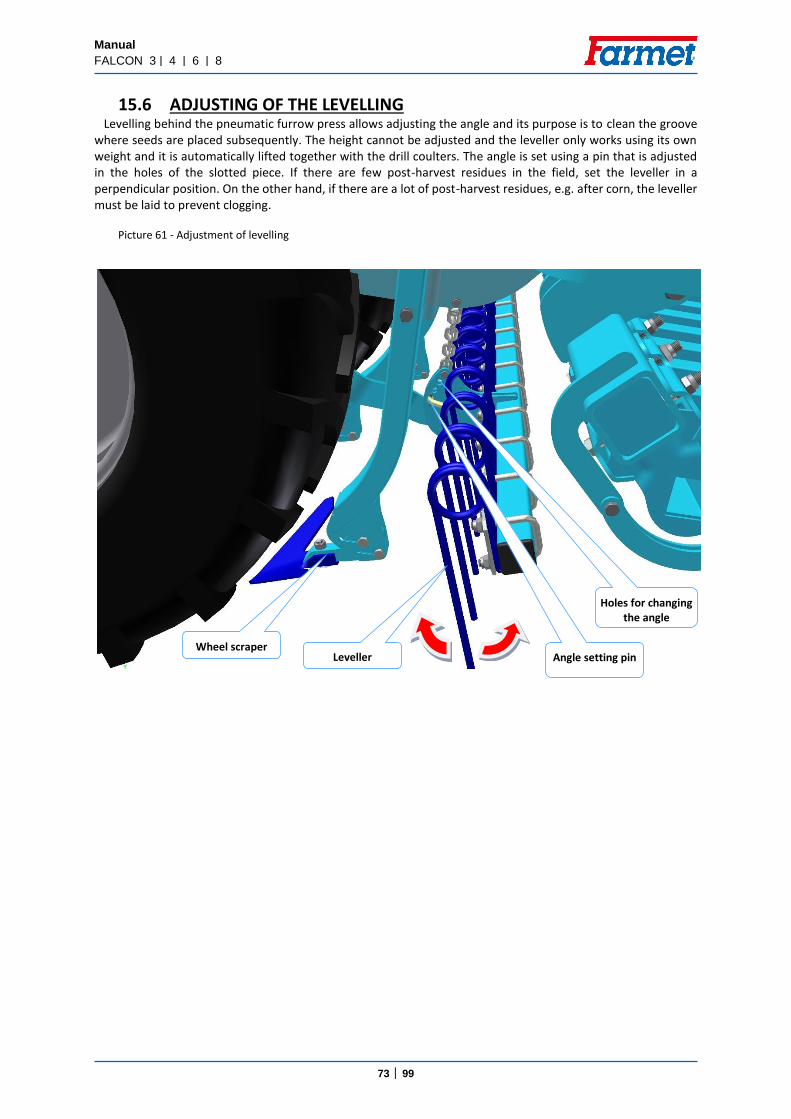
Manual
FALCON 3 | 4 | 6 | 8
73 │ 99
15.6 ADJUSTING OF THE LEVELLING Levelling behind the pneumatic furrow press allows adjusting the angle and its purpose is to clean the groove
where seeds are placed subsequently. The height cannot be adjusted and the leveller only works using its own weight and it is automatically lifted together with the drill coulters. The angle is set using a pin that is adjusted in the holes of the slotted piece. If there are few post-harvest residues in the field, set the leveller in a perpendicular position. On the other hand, if there are a lot of post-harvest residues, e.g. after corn, the leveller must be laid to prevent clogging.
Picture 61 - Adjustment of levelling
Angle setting pin
Leveller
Holes for changing the angle
Wheel scraper

Manual
FALCON 3 | 4 | 6 | 8
74 │ 99
15.7 SETTING OF THE MARKERS The markers can only be adjusted to the centre of the tractor; they trace the terrain and each marker can be
controlled separately and they are hydraulically collapsible. The speed of opening a marker is regulated by choke valves. One rule applies that you should always choke the flow of oil returning from the piston-rods of the markers. That means that the valve on the oil tube returning from the marker piston-rod is throttled (regulated). Set the choke valves as needed and observe all instructions of safety at work.
The guarantee will not be accepted if there has been an unauthorized intervention in the system. In case of any defects in the system, contact the Service Department of the production plant. The distance of the marker disk coverage is always from the centre of the outermost disc body. Always test in practice on the field.
Picture 62 - Setting of the markers

Manual
FALCON 3 | 4 | 6 | 8
75 │ 99
15.8 SETTING OF THE DEEP FERTILIZING DISC Depth of the fertilizer discs is adjusted to the hydroclips according to the sticker on the machine.
Picture 63 - Setting deep of fertilizing

Manual
FALCON 3 | 4 | 6 | 8
76 │ 99
16. ERRORS
SEED SENSORS 00 00 = no error (sensor number) 00 01 = Disconnected cable (number sensor is the last known good sensor) 00 09 = Sensor reset (sensor n / a)
Compatibility The terminal can be incompatible with the job computer for the following reasons:

Manual
FALCON 3 | 4 | 6 | 8
77 │ 99
ISO alarms

Manual
FALCON 3 | 4 | 6 | 8
78 │ 99
Hydraulic alarms
Regulation alarms

Manual
FALCON 3 | 4 | 6 | 8
79 │ 99

Manual
FALCON 3 | 4 | 6 | 8
80 │ 99
Machine-specific alarms

Manual
FALCON 3 | 4 | 6 | 8
81 │ 99

Manual
FALCON 3 | 4 | 6 | 8
82 │ 99

Manual
FALCON 3 | 4 | 6 | 8
83 │ 99

Manual
FALCON 3 | 4 | 6 | 8
84 │ 99
n. Fault Cause Type of cause Removal
1 The fan speed
fluctuates
Incorrectly adjusted fan sensor
Electronic Sensor settings according to the instructions
Faulty fan sensor Electronic Check sensor function, replace
Incorrect or insufficient oil flow
Hydraulic Checking the flow rate of the tractor control, correct adjustment according to tractor type
Small size of free return quick coupling
Hydraulic The size of the free return quick coupler must be min. ISO20
2
The beams are in the
upper position at different heights
Badly welded beams, crooked frames
Mechanical Inspection of beams and frames, or replacement
Unscrew one of the lifting pistons to the end position
Hydraulic Check the piston rods, check the nozzles to prevent any of them from clogging
3
Beam of sowing
coulters are receding at
different heights
Unscrew one of the lifting pistons to the end position
Hydraulic Check the piston rods, check the nozzles to prevent any of them from clogging
Set different depths of stitches on individual frames
Mechanical Check the setting of the end depth stops, correct setting on all the same
Set too much pressure on seed drills
Hydraulic If the soil is very hard and too much pressure is applied to the seed drill, you can not cut any more
When standing on the ground and recessing the bots.
Mechanical
Due to soil resistance, individual beams at different heights can only be lifted so that all the boots are evenly cut into the ground and the beams align themselves
Collisions of individual beams between themselves.
Mechanical The beams are locked in place after the recess. Sometimes you only need to climb and the beams align.

Manual
FALCON 3 | 4 | 6 | 8
85 │ 99
4
From the dispenser or mixer, the
seed flies out
Clogged air system
Mechanical If the main air line is clogged from the dispenser to the distributor, the seed can not pass and flies out of the dispenser.
Too high airflow Mechanical
When the airflow is set too high, the mixer nozzle can generate resistance and instead of leaving the seed further into the distributor, it flows into the mixer to swirl and flutter out.
Too much seed or fertilizer
Electronic
The mixer is beyond the limit of functionality, it does not take more seed and clogs. Reduce the sowing rate or add more air if possible.
5
The dispenser motors do
not spin after the
recess
Badly adjusted antenna sensor
Mechanical Set the sensor so that the sensor turn on
Incorrectly adjusted
pressure sensor Hydraulic
If the sensor is set to low pressure, then at any pressure tip the engine stops. The sensor needs to be tightened.
6
Sowing sensors
often report a flow error
Incorrectly set sensitivity to the
seed Electronic
Check the sensitivity settings and change the setting according to the instructions for the type of seed

Manual
FALCON 3 | 4 | 6 | 8
86 │ 99
7
The machine does not
unfolding as it is, the footpath
goes into a collision with
the front section
Disconnected or faulty quick
couplings at the front section
Hydraulic Check the correct connection of the hydraulic hose couplings to the front section connection.
Faulty end valve for unfolding the
front section Hydraulic
Check that the end valve is not stuck or the stop is in the correct position.
8
The wheels are above
the surface, they do not rotate and
do not work
Poor pressure set Hydraulic Set either very low pressure or very large against a very hard surface. Check and optimize.
9
The main wheels of the main
cylinder are in the air
the machine is not unfolded
Hydraulic The machine is not fully tilted, not tilted by the appropriate hydraulic function.
10
Error: The dispenser does not
rotate
Allowed mechanical
coupling of doser and engine
Mechanical Check the clutch to see if it is allowed, so the motor rotates and the dispenser is standing. Tighten the clamp on the coupling.
Incorrectly adjusted
dispenser sensor Electronic
The engine rotates, but the sensor does not respond and does not count the speed, the system behaves as though the engine was standing. Check whether the diode is illuminated on the sensor or adjust the sensor distance from the star according to the instructions.

Manual
FALCON 3 | 4 | 6 | 8
87 │ 99
11 Disagree
about 50%
Bad dosages required
Electronic Check the sowing batch and set the sowing method, or set it all again according to the instructions.
Incorporated half gears on the
dispenser Mechanical
Check the sowing gears and the correct setting of the dispenser.
Poorly performed and
entered the seed test
Electronic Check the seed drill procedure. For example, you can also exclude the bag weight option. Perform the sowing test again.
12
Does not approve
sowing up to 20%
Badly done seed drill
Electronic Check the seed drill procedure. For example, you can also exclude the bag weight option. Perform the sowing test again.
13
do not correspond
to the hectares
worked per computer
It disagrees with the speed of the radar and reality
Electronic
Wrong insertion of the machine
on the computer Electronic

Manual
FALCON 3 | 4 | 6 | 8
88 │ 99
17. COMPLETION OF SOWING
If there are seeds in container 1 after the sowing has been finished, place a vessel under the discharge chute of the container 2 (see Picture 64) and release the lid 3. Use the turnstile door 4 for seeds that cannot be emptied using the discharge chute.
Picture 64 – Detail of emptying the container
Clean of the doser roller
When you empty the container, we recommend “sowing” a few metres with the empty machine and running fan in order to remove the residues of seeds from the feeder and the whole system of the machine.
Prompt removal of the seed residues, especially when you do not use the machine for a longer period of time, prolongs its usable life and prevents complications in the following operation.
1
2
3
4

Manual
FALCON 3 | 4 | 6 | 8
89 │ 99
Fertilizer metering drive Located below the fertilizer hopper (earlier in the front) → possibility of pulling out the auger without disassembling the drive, trouble-free cleaning.

Manual
FALCON 3 | 4 | 6 | 8
90 │ 99
18. MAINTENANCE AND REPAIRS OF THE MACHINE
Observe the safety instructions for maintenance and treatment. Only persons according to Chapter A.3/p. 9 may perform repairs of the machine. When leaving the tractor
cabin, the operator must switch off all hydraulic circuits and appliances on the machine (ventilator) and the engine and the operator must prevent unauthorized access to the tractor.
The replacement of worn discs can only be executed when the machine is standing still (not operating).
If you have to use welding during a repair and have the machine connected to the tractor, make sure that all supply cables are disconnected from the alternator and accumulator.
Check that all screws and other assembly points are tight before each use of the machine and whenever needed.
Regularly check the wear and tear of the working parts of the machine or replace the worn working parts with new ones.
Adjusting, cleaning and lubricating the machine may only be performed when the machine is standing still (the machine is stopped and is not working).
When the machine is lifted, use an appropriate supporting device propped at designated places or at appropriate places.
When adjusting, cleaning, maintaining and repairing the machine, secure those parts of the machine that could put the operator in danger by fall or other movement.
Repairs of the hydraulic circuits may be performed only when the machine is unfolded and resting on the working bodies on the ground.
When repairing the hydraulic circuits of the machine, first remove pressure from the hydraulic circuits of the machine with the use of control levers of the hydraulic system in the tractor cabin.
For attaching the machine when manipulating it with the use of lifting equipment, use only places marked by stick-on labels with the symbol of a chain „ “.
If there is a defect or damage on the machine, immediately turn off the tractor engine and secure the engine
from turning on, secure the machine against movement then you can remove the defect.
When repairing the machine, use only original spare parts, suitable tools and protective equipment.
Check the prescribed pressure in the tyres of the machine and the condition of the tyres regularly. Execute potential repairs of tyres in a professional workshop.
Keep the machine clean.
Do not use a high-pressure cleaner or direct water jet for cleaning hydraulic rolls (piston rod) and bearings and electronic parts. The bearings and seals are not waterproof under high pressure.
18.1. REPLACEMENT OF WORN DISCS When replacing discs, always observe safety regulations and directives.
The machine must be aggregated with the tractor according to Chapter “6.1/P.18” for the replacement of the discs. The tractor engine must be switched off and the operator or the mechanic must prevent unauthorized access to the tractor.
The machine must be lifted on the transport axle and in the arms of the tractor for the replacement of the discs.
Raise the rear tractor TPS shoulders with the aggregated machine to the maximal position and secure it from falling. Then you may perform the replacement of worn shares.
The ball valve of the axle must be in the “closed” position, see Picture 30/P.49. You must ensure mechanical supports under the pole of the machine in case the tractor hydraulic system is not tight.
Only replace the discs on a firm and flat ground and when the machine is in standstill.

Manual
FALCON 3 | 4 | 6 | 8
91 │ 99
18.2. MAINTENANCE PLAN
MAINTENANCE PLAN Perform planned maintenance according to the instructions:
Maintenance task Daily (season)
1x week
Before the
season
After the season
Time interval
Machine in general Visual check of the machine
Monitoring undesirable sounds, vibrations and excessive wear and tear
X
Checking crucial nodes: pins, bearings, rollers, working parts X X X
Cleaning the machine
Storing the machine under the roof, if possible
Record the mileage of the machine/season (ha) X X
Complete inspection
Checking the frame X X
Do not use a high-pressure cleaner or direct water jet for cleaning hydraulic rolls (piston rod) and bearings and electronic parts. The bearings and seals are not waterproof under high pressure.
Hydraulic system Checking the function, tightness, mounting and worn spots of all hydraulic components and hoses
X X Hydraulic hoses – replacement:
Damaged outer casing of the hose (mechanically or rotten)
Fluid leakage (mostly in end pieces)
Bulges or blisters on the hose
Deformed or corroded end piece
Loosened end piece – the hose spins
X X
Hydraulic hoses – replacement:
Useful life of the hose is exceeded
6 years
!!! PREVENTION means removing the problem according to the plan, outside the season, without stress and comfortably, before a secondary problem, accident or risk of injury occurs.

Manual
FALCON 3 | 4 | 6 | 8
92 │ 99
MAINTENANCE PLAN Perform planned maintenance according to the instructions:
Maintenance task Daily (season)
1x week
Before the season After the
season
Time interval
Screw connections Visual check of screw and hydraulic connections, tighten any loosened connections with a corresponding torque (tab. Torque)
X X
Wheels – tighten all wheel nuts.
First, after 10 hours of operation
Wheel replacement, after 10 hours of operation
M 18 x 1.5 300 Nm
M 20 x 1.5 400 Nm
M 22 x 1.5 500 Nm
X X
Brake system Brake line and hoses – checking the function, tightness, mounting and clamping, or breaking
X X X
Brake components – checking the function, tightness, mounting X X X
Air nozzle – draining with the drain valve X X Drain valve – checking the function, cleaning and replacement of sealing X X
Pipe filter – cleaning X X Brake/parking brake – checking the function,
adjustment 25-45mm X Brake lining – checking the condition of the brake lining, min. thickness 3mm X
Wheels/axle Checking tyre pressure 405/70 R20 X X For FALCON PRO only
Transport axle bearings – check and adjustment of allowance (in the workshop) X

Manual
FALCON 3 | 4 | 6 | 8
93 │ 99
MAINTENANCE PLAN Perform planned maintenance according to the instructions:
Maintenance task Daily (season)
1x week
Before the
season
After the
season
Time interval
Pneumatic system Fan: Revolution setting function
X Fan guard:
Checking the condition, removal of debris X
Fan impeller
Checking the condition and mounting, removal of debris
Checking the mounting of the fan drive
X
Fan, seeding hoses, mixer:
Tightness, clamping points, clogging, overall condition
X X
Hydraulic joints and hoses:
Tightness of all components and permeability X
Distributor:
Checking for foreign particles. Unscrew the lid of the distributor and check the outlets
Checking the function and position of rail line flaps
X
Seeding mechanism (dispenser) Checking the overall condition, setting, wear and tear, tightness X
Checking for foreign particles X Checking the condition of the drive, motor bearings X Checking the tightness of the roller board X
!!! PREVENTION means removing the problem according to the plan, outside the season, without stress and comfortably, before a secondary problem, accident or risk of injury occurs.

Manual
FALCON 3 | 4 | 6 | 8
94 │ 99
MAINTENANCE PLAN Perform planned maintenance according to the instructions:
Maintenance task Daily (season)
1x week
Before the
season
After the
season
Time interval
Checking for damage, potential replacement X X Safety equipment Lighting and safety hatched boards – checking the condition, function and cleanliness X X Warning and safety labels – checking that they are installed and legible X
Machine lubrication plan Drawbar knuckle/lifting lug – plastic lubricant X X Hand brake bolt – plastic lubricant or suitable grease X X Axle bearings – plastic lubricant containing Lithium – check, refill when needed X
After the season Whole machine
Treat and clean the machine; do not spray oil or similar agents on the plastic parts Spray the piston-rods of the hydraulic rollers with suitable anti-corrosion agents Check that all screw and plug-in connections for tightness (see the table of Torque) Check for any damage of the electric lines and replace them when needed
Brake system
Use anti-free liquid (approx. 0.1 L) without ethanol before the last drive, acc. to the recommendation of the tractor manufacturer.
Secure the machine against movement with scotch blocks. Release the parking brake, let the air out of the air nozzle and close the brake lines.
The operating brake and hand brake must be released during winter to prevent sticking to the brake drum. Points of lubrication
Lubricate the points of lubrication according to the plan, use plastic lubricant KP2P-20 Likx acc. to DIN 51 502
!!! PREVENTION means removing the problem according to the plan, outside the season, without stress and comfortably, before a secondary problem, accident or risk of injury occurs.
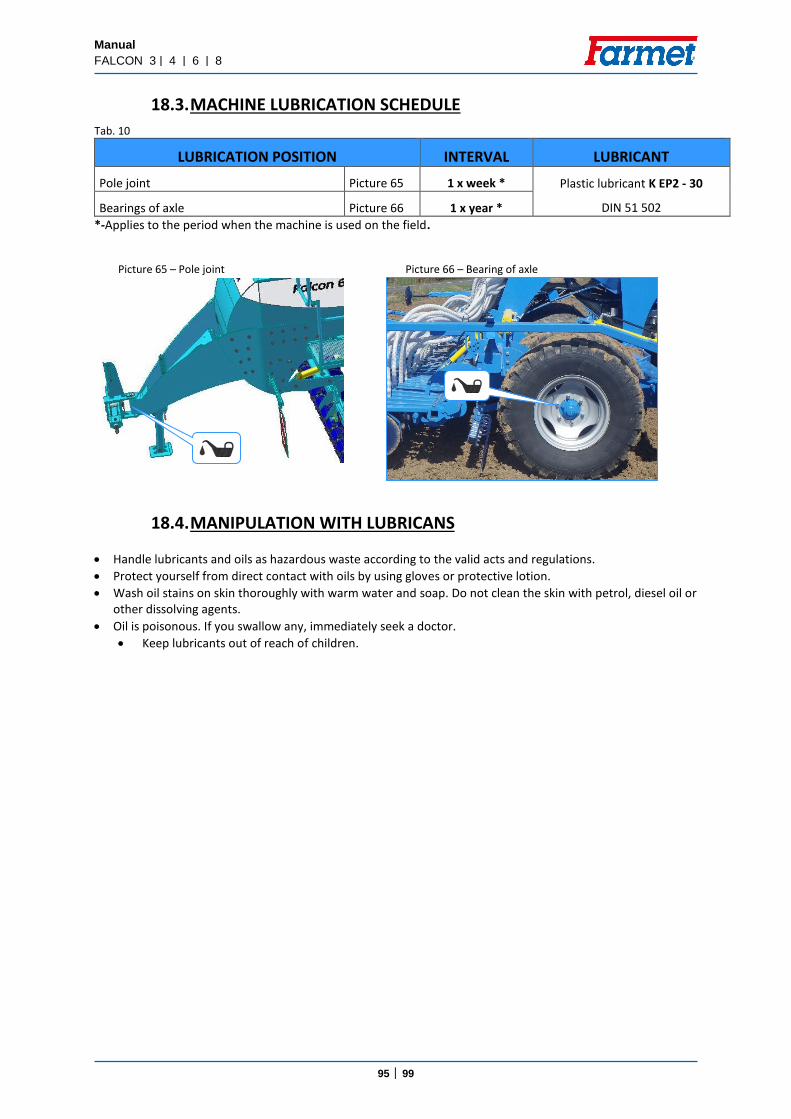
Manual
FALCON 3 | 4 | 6 | 8
95 │ 99
18.3. MACHINE LUBRICATION SCHEDULE
Tab. 10
LUBRICATION POSITION INTERVAL LUBRICANT
Pole joint Picture 65 1 x week * Plastic lubricant K EP2 - 30
DIN 51 502 Bearings of axle Picture 66 1 x year *
*-Applies to the period when the machine is used on the field.
Picture 65 – Pole joint Picture 66 – Bearing of axle
18.4. MANIPULATION WITH LUBRICANS
Handle lubricants and oils as hazardous waste according to the valid acts and regulations.
Protect yourself from direct contact with oils by using gloves or protective lotion.
Wash oil stains on skin thoroughly with warm water and soap. Do not clean the skin with petrol, diesel oil or other dissolving agents.
Oil is poisonous. If you swallow any, immediately seek a doctor.
Keep lubricants out of reach of children.
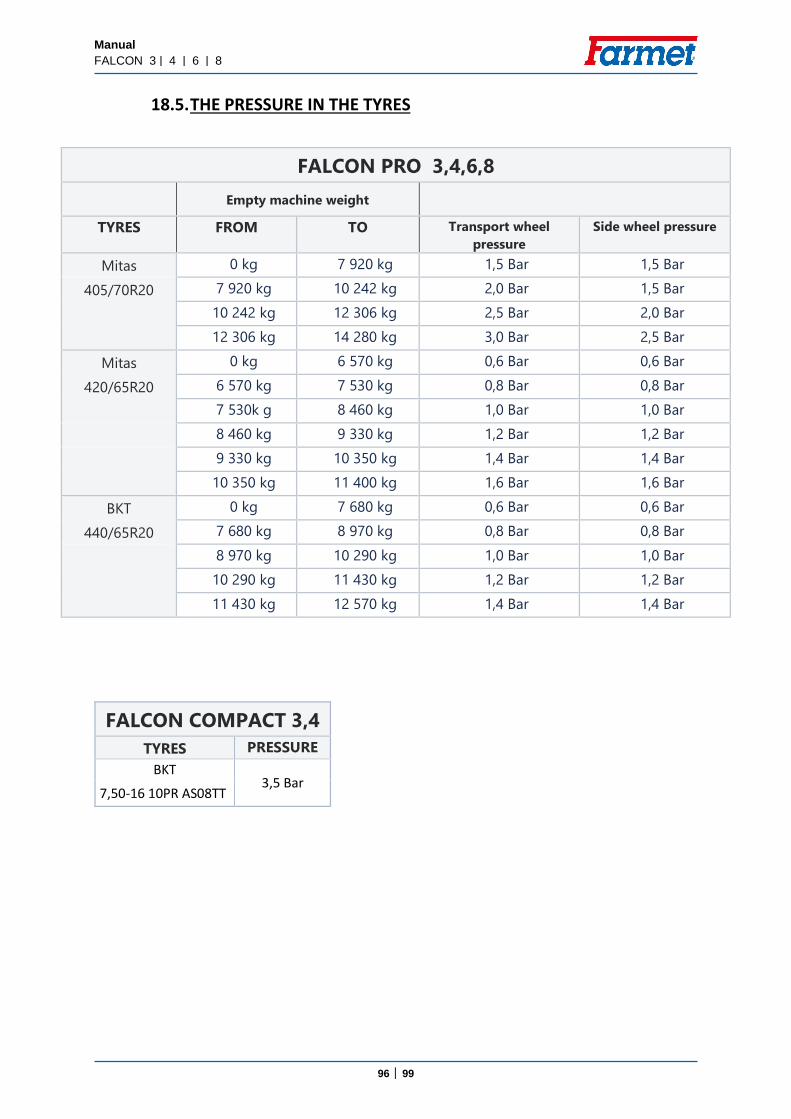
Manual
FALCON 3 | 4 | 6 | 8
96 │ 99
18.5. THE PRESSURE IN THE TYRES
FALCON PRO 3,4,6,8
Empty machine weight
TYRES FROM TO Transport wheel
pressure
Side wheel pressure
Mitas 0 kg 7 920 kg 1,5 Bar 1,5 Bar
405/70R20 7 920 kg 10 242 kg 2,0 Bar 1,5 Bar
10 242 kg 12 306 kg 2,5 Bar 2,0 Bar
12 306 kg 14 280 kg 3,0 Bar 2,5 Bar
Mitas 0 kg 6 570 kg 0,6 Bar 0,6 Bar
420/65R20 6 570 kg 7 530 kg 0,8 Bar 0,8 Bar
7 530k g 8 460 kg 1,0 Bar 1,0 Bar
8 460 kg 9 330 kg 1,2 Bar 1,2 Bar
9 330 kg 10 350 kg 1,4 Bar 1,4 Bar
10 350 kg 11 400 kg 1,6 Bar 1,6 Bar
BKT 0 kg 7 680 kg 0,6 Bar 0,6 Bar
440/65R20 7 680 kg 8 970 kg 0,8 Bar 0,8 Bar
8 970 kg 10 290 kg 1,0 Bar 1,0 Bar
10 290 kg 11 430 kg 1,2 Bar 1,2 Bar
11 430 kg 12 570 kg 1,4 Bar 1,4 Bar
FALCON COMPACT 3,4
TYRES PRESSURE
BKT 3,5 Bar
7,50-16 10PR AS08TT
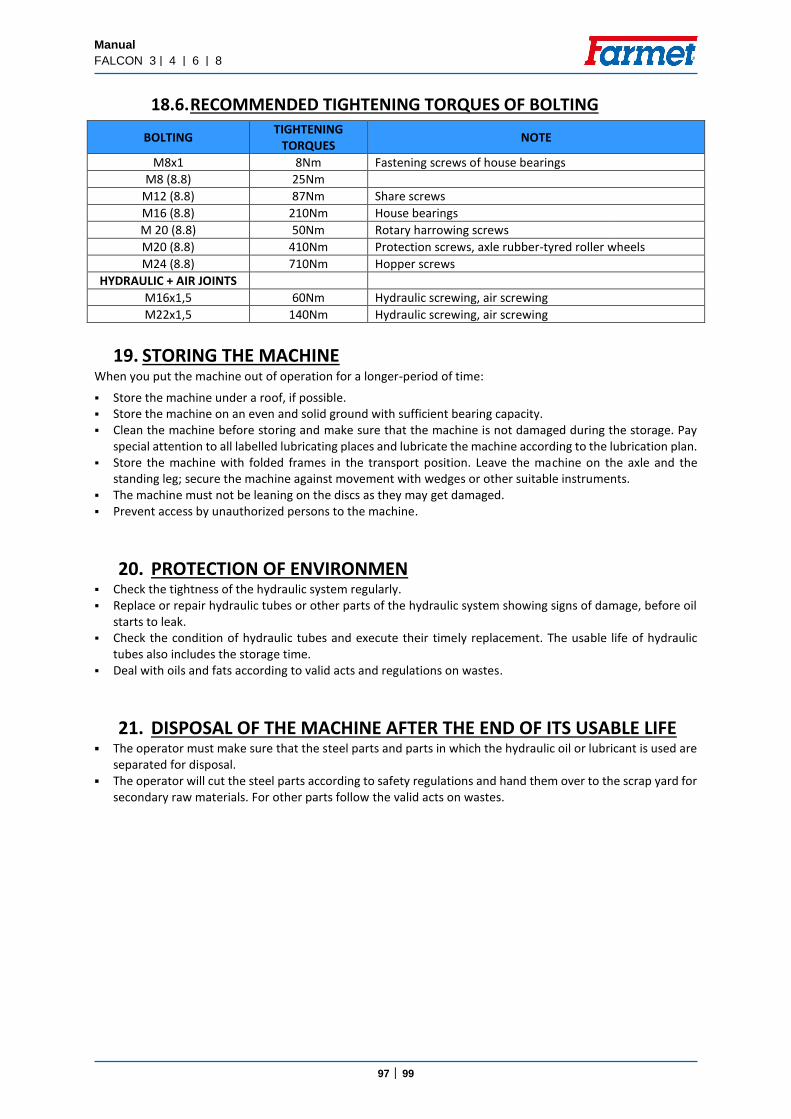
Manual
FALCON 3 | 4 | 6 | 8
97 │ 99
18.6. RECOMMENDED TIGHTENING TORQUES OF BOLTING
BOLTING TIGHTENING
TORQUES NOTE
M8x1 8Nm Fastening screws of house bearings
M8 (8.8) 25Nm
M12 (8.8) 87Nm Share screws
M16 (8.8) 210Nm House bearings
M 20 (8.8) 50Nm Rotary harrowing screws
M20 (8.8) 410Nm Protection screws, axle rubber-tyred roller wheels
M24 (8.8) 710Nm Hopper screws
HYDRAULIC + AIR JOINTS
M16x1,5 60Nm Hydraulic screwing, air screwing
M22x1,5 140Nm Hydraulic screwing, air screwing
19. STORING THE MACHINE When you put the machine out of operation for a longer-period of time:
Store the machine under a roof, if possible. Store the machine on an even and solid ground with sufficient bearing capacity. Clean the machine before storing and make sure that the machine is not damaged during the storage. Pay
special attention to all labelled lubricating places and lubricate the machine according to the lubrication plan. Store the machine with folded frames in the transport position. Leave the machine on the axle and the
standing leg; secure the machine against movement with wedges or other suitable instruments. The machine must not be leaning on the discs as they may get damaged. Prevent access by unauthorized persons to the machine.
20. PROTECTION OF ENVIRONMEN Check the tightness of the hydraulic system regularly. Replace or repair hydraulic tubes or other parts of the hydraulic system showing signs of damage, before oil
starts to leak. Check the condition of hydraulic tubes and execute their timely replacement. The usable life of hydraulic
tubes also includes the storage time. Deal with oils and fats according to valid acts and regulations on wastes.
21. DISPOSAL OF THE MACHINE AFTER THE END OF ITS USABLE LIFE The operator must make sure that the steel parts and parts in which the hydraulic oil or lubricant is used are
separated for disposal. The operator will cut the steel parts according to safety regulations and hand them over to the scrap yard for
secondary raw materials. For other parts follow the valid acts on wastes.

Manual
FALCON 3 | 4 | 6 | 8
98 │ 99
22. MAINTENANCE AND TERMS OF GUARANTEE
22.1. MAINTENANCE Maintenance is provided by a business representative after a consultation with the producer or by the
producer. Spare parts are provided through the sales network of individual sellers all over the Czech Republic. Use only spare parts according to the Spare Parts Catalogue officially published by the producer.
22.2. GUARANTEE The producer provides 24-month guarantee for the following parts of the machine: main frame, axle
and pole of the machine. The producer provides 12-month guarantee for the remaining parts of the machine. The guarantee starts on the date of the sale of the new machine to the end consumer (user).
The guarantee applies to hidden defects that appear during the proper use of the machine during the guarantee period and according to the terms and conditions stated in the operating manual.
The guarantee does not apply to spare parts that can be worn out, i.e. to regular wear and tear of replaceable working parts (shares, blades etc.).
The guarantee does not apply to indirect consequences due to potential damage, such as decrease in the usable life etc.
The guarantee is related to the machine and does not cease to exist when the owner changes.
The guarantee is limited to disassembly and assembly, or replacement or repair of the faulty part. The contractual service of the company Farmet a.s. decides whether the faulty part will be replaced or repaired.
Only the authorized service technician of the producer may perform repairs or other interventions in the machine during the guarantee period, otherwise the guarantee will not be accepted. This provision does not apply to the replacement of spare parts that can be worn out.
The guarantee is conditioned by the use of original spare parts of the producer.
Issued by: Technical Department, Farmet a.s., Jiřinková 276, Česká Skalice 552 03, on 11/08/2020, Changes are reserved
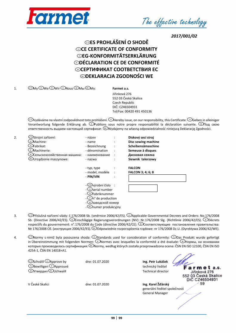
99 │ 99
2017/001/02
ES PROHLÁŠENÍ O SHODĚ CE CERTIFICATE OF CONFORMITY EG-KONFORMITÄTSERKLÄRUNG
DÉCLARATION CE DE CONFORMITÉ СЕРТИФИКАТ СООТВЕТСТВИЯ ЕС
DEKLARACJA ZGODNOŚCI WE
1. My We Wir Nous Мы My: Farmet a.s.
Jiřinková 276 552 03 Česká Skalice
Czech Republic DIČ: CZ46504931 Tel/Fax: 00420 491 450136
Vydáváme na vlastní zodpovědnost toto prohlášení. Hereby issue, on our responsibility, this Certificate. Geben in alleiniger
Verantwortung folgende Erklärung ab. Publions sous notre propre responsabilité la déclaration suivante. Под свою ответственность выдаем настоящий сертификат. Wydajemy na własną odpowiedzialność niniejszą Deklarację Zgodności.
2. Strojní zařízení: - název : Diskový secí stroj
Machine: - name : Disc sowing machine Fabrikat: - Bezeichnung : Scheibensämaschine Machinerie: - dénomination : Semeuse à disques Сельскохозяйственная машина: - наименование : Дисковая сеялка
Urządzenie maszynowe: - nazwa : Siewnik talerzowy - typ, type : FALCON - model, modèle : FALCON 3; 4; 6; 8
- PIN/VIN : - výrobní číslo : - serial number - Fabriknummer - n° de production - заводской номер - numer produkcyjny 3. Příslušná nařízení vlády: č.176/2008 Sb. (směrnice 2006/42/ES). Applicable Governmental Decrees and Orders: No.176/2008
Sb. (Directive 2006/42/ES). Einschlägige Regierungsverordnungen (NV): Nr.176/2008 Slg. (Richtlinie 2006/42/ES). Décrets respectifs du gouvernement: n°.176/2008 du Code (directive 2006/42/CE). Соответствующие постановления правительства: № 176/2008 Сб. (инструкция 2006/42/ES). Odpowiednie rozporządzenia rządowe: nr 176/2008 Dz.U. (Dyrektywa 2006/42/WE).
4. Normy s nimiž byla posouzena shoda: Standards used for consideration of conformity: Das Produkt wurde gefertigt
in Übereinstimmung mit folgenden Normen: Normes avec lesquelles la conformité a été évaluée: Нормы, на основании которых производилась сертификация: Normy, według których została przeprowadzona ocena: ČSN EN ISO 12100, ČSN EN ISO 4254-1, ČSN EN 14018+A1.
Schválil Approve by dne: 01.07.2020 Ing. Petr Lukášek
Bewilligen Approuvé technický ředitel
Утвеpдил Uchwalił Technical director
V České Skalici dne: 01.07.2020 Ing. Karel Žďárský generální ředitel společnosti General Manager
CZ
GB
D
F
RU
PL
CZ GB
D F RU
PL
CZ GB
D
F RU
PL
CZ
GB D
F
RU PL
CZ
GB D
F
RU PL
CZ GB
D F
RU
PL
CZ GB
D
F RU
PL
CZ GB
D F
RU
PL