operating manual da-60 - imr usa · ta luft accredited page 4 dustalert 60 user manual 6.01:...
TRANSCRIPT

Environmental Equipment, Inc. 3634 Central Ave. · St. Petersburg, Florida 33711 · Phone 727-328-2818 · 800-RING-IMR · FAX 727/328-2826 · E-mail: [email protected]
www.imrusa.com
www.imrusa.com© Copyright 2004 IMR Environmental Equipment, Inc.
OPERATING MANUAL
DA-60

TA LUFT
ACCREDITED
DUSTALERT 60 USER MANUAL page 3
TABLE OF CONTENTS
SAFETY .............................................................................................................................5 Electrical Safety;..........................................................................................................................................5 Danger From Process;..................................................................................................................................5 ATEX Approved Versions (DA60-x);.........................................................................................................5
2.0 – INTRODUCTION ................................................................................................7 1.01: Overview; ...........................................................................................................................................7 1.02: How does it work?..............................................................................................................................7 1.03: Features; .............................................................................................................................................7 1.04: The Dust Alert 60 Control & Sensor Unit; .........................................................................................8
2.00 – INSTALLING THE SENSOR...............................................................................9 2.01: Choosing the best position for the sensor; ..........................................................................................9 2.02: Sensor mechanical installation;...........................................................................................................9 2.03: Setting up the (optional) air purge; ...................................................................................................10 2.04: The sensor unit electrical connections; .............................................................................................10 2.05: Running the cable between control unit and sensor;.........................................................................11
3.00 – INSTALLING THE CONTROL UNIT .............................................................13 3.01: Choosing the best position for the control unit; ................................................................................13 3.02: Control unit mechanical installation; ................................................................................................13 3.03: Connecting the sensor cable to the control unit; ...............................................................................13 3.04: Connecting the mains supply to the control unit;..............................................................................14 3.05: Connecting to the 4-20mA output; ...................................................................................................14 3.06: Connecting to alarm relay 1;.............................................................................................................15 3.07: Connecting to alarm relay 2;.............................................................................................................15 3.08: Connecting the broken bag row marker input (Optional); ................................................................16 3.09: Connecting the dust monitor to the PC (Optional); ..........................................................................16
4.00 - GETTING STARTED ..........................................................................................17 4.01: Powering up for the first time; ..........................................................................................................17 4.02: Error Code Diagnostics (ECD);........................................................................................................17 4.03: ECD on the bargraph display;...........................................................................................................17 4.04: Compound ECD codes; ....................................................................................................................18 4.05: Causes & remedies for ECD codes;..................................................................................................18
5.00 - OPERATION.........................................................................................................21 5.01: Terminology; ....................................................................................................................................21 5.02: Understanding the bargraph display; ................................................................................................21 5.03: The front panel control keys; ............................................................................................................22 5.04: The function lamp display; ...............................................................................................................22 5.05: Modes of operation;..........................................................................................................................23 5.06: Entering the password; .....................................................................................................................23 5.07: Wrong password entry;.....................................................................................................................24 5.08: Password ‘lockout’ mode; ................................................................................................................24 5.09: When the Password is accepted;.......................................................................................................24 5.10: Changing the Password;....................................................................................................................25 5.11: Alarm Outputs; .................................................................................................................................26
6.00 - CHANGING THE INSTRUMENT SETTINGS................................................28

TA LUFT
ACCREDITED
page 4 DUSTALERT 60 USER MANUAL
6.01: Initial Set-up; ................................................................................................................................... 28 6.02: Adjusting the scaling factor; ............................................................................................................ 28 6.03: Setting the Data Smoothing; ............................................................................................................ 29 6.04: Setting the Alarm Delay;.................................................................................................................. 30 6.05: Setting the Alarm Levels;................................................................................................................. 31 6.06: Alarm Operation .............................................................................................................................. 33 6.07: Setting the 4-20mA range; ............................................................................................................... 34
7.00 - GETTING THE MOST FROM THE DUSTALERT 60 .................................. 36 7.01: Viewing the process; ........................................................................................................................ 36 7.02: Hints for setting the Data smoothing;............................................................................................... 37 7.03: Hints for setting the Alarm level and Alarm delay;.......................................................................... 38 7.04: Hints for setting the 4-20mA range;................................................................................................. 38
APPENDIX A - INTERNAL JUMPER SETTINGS ................................................... 40 A1: Enabling and disabling the SET key; ................................................................................................. 41 A2: Fail-safe operation;............................................................................................................................. 42 A3: Setting latching or non-latching alarms;............................................................................................. 43 A4: The Sensor Sensitivity Jumper; .......................................................................................................... 44 A5. Restart after Power Failure................................................................................................................. 45 A6. Restoring Factory Settings ................................................................................................................. 45
APPENDIX B - TABLES AND FACTORY SETTINGS ............................................ 46 B1: Function settings & options table; ...................................................................................................... 47 B2: The ECD code table; .......................................................................................................................... 48
APPENDIX C - TROUBLESHOOTING & MAINTENANCE.................................. 50 C1: General maintenance; ......................................................................................................................... 51 C2: Troubleshooting; ................................................................................................................................ 52
APPENDIX D - SYSTEM ELECTRICAL DETAILS................................................. 54 D1: Cable preparation details;................................................................................................................... 55 D2: The 4-20mA output fuse location;...................................................................................................... 56 D3: Control unit connection diagram;....................................................................................................... 57 D4: Sensor unit connection diagram; ........................................................................................................ 58
APPENDIX E - SUPPORT DOCUMENTATION....................................................... 60
INDEX.............................................................................................................................. 61

TA LUFT
ACCREDITED
DUSTALERT 60 USER MANUAL page 5
SAFETY Electrical Safety; • This equipment contains hazardous voltages. • This equipment should only be installed by qualified personnel. • This equipment must be earthed. • Live and Neutral must not be reversed (the Neutral line is not fused). • The Low Voltage Directive EN 60950-1:2002 states in clause 3.2.5.1 that the power supply cord
shall be “Not lighter than light PVC sheathed flexible cord according to IEC 60227 (designation H03 VV-F or H03 VVH2-F)” The conductor area shall not be less than 0.75mm2.
• The earth wire in the mains cable shall be the longest so if the cable is pulled, the earth wire is the last to take the strain.
• This equipment must be powered off before opening the case. This equipment does not contain a power disconnect device, so must be fitted with a readily accessible external disconnect device and fuse in the power wiring. The disconnect device shall disconnect both poles of the supply, shall have a contact separation not less than 3mm, and shall be mounted as closely as practicable to the incoming supply.
• Hazardous voltages are still present when the mains fuse has failed. • The 4-20mA outputs and the Host / PC communications outputs (where fitted) are isolated and safe
to touch (they are SELV circuits in accordance with EN 60950-1:2001). They must only be connected to other SELV circuits.
• This equipment is designed to operate from either:
115Vac or 230Vac
Danger From Process; It is possible that the sensors are installed in ducting containing process particulate, which is injurious to health. This may take one or more of the following forms: ♦ Particulate which is inflammable or explosive. ♦ Particulate which is toxic or in some other way injurious to health. ♦ Particulate contained within high temperature gas. Unless the process conditions are known to be entirely safe, suitable precautions such as the use of breathing apparatus or duct purging/detoxifying must be employed before any entry is made into the duct for installation or maintenance purposes. If in doubt, consult the local Safety Officer and/or local Safety procedures.
ATEX Approved Versions (DA60-x); For ATEX approved versions (Category 1, suitable for dust zones 20,21,22). This manual applies to the operation and use of the Instrument and installation of the Control Unit, but should not be used in relation to installation of the Sensor or Isolated Spur. These issues are covered in the DA-x Sensor Manual.

TA LUFT
ACCREDITED
page 6 DUSTALERT 60 USER MANUAL

TA LUFT
ACCREDITED
DUSTALERT 60 USER MANUAL page 7
2.0 – INTRODUCTION 1.01: Overview; The DUSTALERT 60 is one of a family of Electrodynamic intelligent filter performance monitors specifically designed to accurately follow particulate emissions from small stacks and emission points. Using advanced Microprocessor technology, the DUSTALERT 60 is able to be scaled to provide an indication of dust concentration and can provide alarm outputs to alert the operator of any abnormalities outside a preset limit. The DUSTALERT 60 is able to reject the typical type of short-term abnormalities found in dust arrestment plant, thus reducing time wasting unwanted alarms. The DUSTALERT 60 is an INDICATIVE monitor and can be used to satisfy environmental legislation (EPA 1990 in the UK) and to provide the operator with an indication of the integrity of the dust arrestment equipment. The DUSTALERT 60 comprises of two main parts, a SENSOR UNIT and a CONTROL UNIT. The Sensor unit has a metal probe rod mounted to a small enclosure containing electronic circuitry. The sensor is connected to the Control unit, (by a cable up to 500M in length), which contains the user controls and display. The Sensor unit is mounted to the ductwork such that the metal probe rod protrudes into the flow of the particulate to be monitored.
1.02: How does it work? The DUSTALERT 60 utilises the proven and reliable PCME Electrodynamic® measurement principle. Particles in the air stream interact with the sensing rod and a charge induction affect is analysed from the probe. Distributions in the particle stream result in a frequency charge induction response, which is directly proportional to the concentration of the particulate. Independent laboratory tests have validated the Electrodynamic technique and the DUSTALERT 60 is covered by a TA-LUFT approval according to BIMSCH 27. Experience has shown that this method of particulate monitoring will provide accurate results with minimal maintenance for many years.
1.03: Features; Dynatrack The DA60 automatically adjusts its dynamic range to track fast duration dust pulses
(typically found after reverse jet cleaning bag houses) to ensure accurate measurement. AGC Auto Gain Control: The DA60 automatically selects the optimum gain range (no user
adjustments are necessary). AZC Auto Zero Check: The DA60 is automatically compensated for zero drift due to
frequency derived signal processing. Alpha Check In-built system checking, processor driven for system integrity. Beta Check Digital communications check for sensor integrity. ECD In-built Error Code Diagnostics visually displayed for user information.
TA LUFT
ACCREDITED
page 8 DUSTALERT 60 USER MANUAL
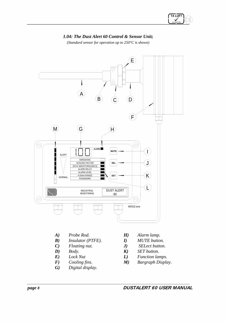
1.04: The Dust Alert 60 Control & Sensor Unit; (Standard sensor for operation up to 250°C is shown)
A) Probe Rod. H) Alarm lamp. B) Insulator (PTFE). I) MUTE button. C) Floating nut. J) SELect button. D) Body. K) SET button. E) Lock Nut L) Function lamps. F) Cooling fins. M) Bargraph Display. G) Digital display.
INDUSTRIALMONITORING
ALARM
60f102.ecw
DUST ALERT60
MUTE
SEL
SETNORMAL
ALERT
EMISSIONSSCALING FACTOR
DATA SMOOTHING(SECS)ALARM DELAYALARM LEVEL4-20mA RANGE
PASSWORD
E
AB C D
F
G H
I
J
K
L
M

TA LUFT
ACCREDITED
DUSTALERT 60 USER MANUAL page 9
2.00 – INSTALLING THE SENSOR IMPORTANT: This section does not apply to the DA60x, Atex (Category 1,2,3) approved instrument. For this information, consult the separate DA-x Sensor Manual.
2.01: Choosing the best position for the sensor; The best position for the sensor unit is in a section of ductwork where the particulate has an even distribution and the flow is linear. This would ideally be in a vertical or horizontal section of duct, having no bends or obstructions for at least three duct diameters downstream or upstream. In many applications, a compromise must be made, and the sensor would be fitted in a position that satisfies the majority of the above requirements. The sensor must be fitted to metal ductwork in order to be electrically screened from interference signals. The sensor unit should not be mounted in direct sunlight or in areas where the ambient temperature is above 50 degrees centigrade. If you require further advice on any installation aspects, i.e. position, fitment to a non-metallic duct, etc., please consult us.
To summarize, the sensor should be mounted: • In the longest, straightest, most vertical, unrestricted section of ductwork available. • In metallic ductwork, (for non-metallic ductwork consult us) • Away from ambient or radiated temperatures exceeding 50 degrees Centigrade.
2.02: Sensor mechanical installation; The diagram below shows the components involved in the sensor unit installation. The passage below refers to the components in this diagram.
1 2 3
4
6
5
60f202
1) 1.5" Socket2) 1.5" Floating nut3) Locknut4) Sensor housing5) Duct wall6) Probe rod

TA LUFT
ACCREDITED
page 10 DUSTALERT 60 USER MANUAL
When the optimum position has been decided for the sensor unit, a 1.5” BSP SOCKET (1) should be fitted to the ductwork (this is not provided). The sensor unit is then simply inserted into the socket on the duct and the floating nut (2) on the sensor body is slid along to mate with the thread in the socket (1). Be careful to ensure that the probe rod (6) does not touch the opposite side of the duct (the probe rod should usually span about half the width of the duct). The locknut (3) must then be tightened against the floating nut using an adjustable spanner to lock the sensor firmly in position. For optimum heat dissipation, the sensor unit should be mounted such that the heat sinking fins on each side of the enclosure are vertical. Do not try to rotate the sensor unit by grasping the enclosure after the locknut has been tightened because damage to the environmental seal may occur. If the sensor must be rotated, first loosen the locknut, then rotate the sensor unit to the required position and finally re-tighten the locknut. To summarise, to install the sensor unit you must: • Cut a hole in the ductwork and weld a 1.5” BSP SOCKET in position. • Position the sensor unit with the heat sink fins vertical. • Ensure that the probe rod does not reach the opposite duct wall. • Tighten the floating nut into the 1.5” BSP SOCKET. • Securely tighten the locknut against the floating nut to lock the sensor in position (This must also
provide a good electrical connection to earth the sensor). 2.03: Setting up the (optional) air purge; An optional air purge may be fitted to the sensor unit to prevent bridging in damp or conductive particulate applications. This will be supplied correctly fitted to the sensor, and is mounted with the sensor as a complete unit. The air purge requires a supply of oil-free instrument quality air at up to 1 CFM and a pressure of at least 4 bar g. Air connection to the air purge is by a ¼” BSP fitting. The pressure regulator fitted to the air purge should be adjusted to give a positive displacement of air from the purge outlet. (It is best to adjust the airflow before fitting the sensor to the ductwork).
2.04: The sensor unit electrical connections;
Remove the sensor lid then pass the
cable through the cable entry gland and connect to the detachable header within the sensor unit using the colour coding shown in the figure to the left. Connect the back and screen cores together then use an M6 crimp eyelet and fix under the mounting screw as shown. Try to keep the length of the cables within the sensor as short as possible. Ensure that the cable gland is securely tightened on completion!
1234567
SENSOR UNIT(with lid removed)
VIOLET & WHITEBLUE
REDNOT CONNECTED
YELLOWGREEN
BROWN
BLACK & SCREEN

TA LUFT
ACCREDITED
DUSTALERT 60 USER MANUAL page 11
2.05: Running the cable between control unit and sensor; The cable should be fixed such that it is free from excessive vibration and such that it is not under strain. It should be secured in accordance with good engineering practice (using cable trays where possible), and careful consideration should be given to positioning of the cable such that it is not easily damaged. Care taken during the installation of the cable will give a long and maintenance-free life and will avoid possible future damage to the control and sensor units. To summarise, the cable should be installed such that; • Heavy vibration is minimised to prevent fatigue and failure. • It is not vulnerable to accidental damage. • The sealed connector is positioned near to the sensor unit. • It is away from sources of large electromagnetic fields (where possible).
TA LUFT
ACCREDITED
page 12 DUSTALERT 60 USER MANUAL

TA LUFT
ACCREDITED
DUSTALERT 60 USER MANUAL page 13
3.00 – INSTALLING THE CONTROL UNIT 3.01: Choosing the best position for the control unit; The control unit should be mounted in an easily accessible position, away from direct sunlight and in an area where the ambient temperature does not exceed -20 to +50 degrees C. Ideally the control unit will be mounted in a position where the display is clearly visible to the operator, i.e. in the control room. The enclosure of the control unit is sealed to IP65 and thus the unit may be mounted outside, preferably in a sheltered position away from the elements. Consideration should be given to the connection cable between the sensor unit and control unit, and a balance between excessive cable length and convenient location for the control unit will have to be found. The maximum permissible length of cable between the control unit and the sensor unit is 500 metres (dependent upon cable type, 10 metres supplied as standard). To summarize, the control unit should be mounted: • In a convenient and accessible position. • In an area within the temperature range (-20 to +50 degrees C). • Away from direct sunlight and sheltered from the elements. • As near to the sensor unit as conveniently possible.
3.02: Control unit mechanical installation; Once the optimum position for the control unit has been decided, open the lid of the control unit by undoing the four screws at the front. This will reveal four deeply recessed mounting holes, one in each corner. The control unit will then be fixed into position by passing a suitable fastener (i.e. screws) through the mounting hole and into the surface to which the control unit is to be mounted.
3.03: Connecting the sensor cable to the control unit; Referring to the diagram to the right of this text, the 8 core cable from the sensor should be passed through the leftmost cable gland and connected in accordance with the colour code as shown The black core and the screen should be twisted together and have an M6 eyelet crimped or soldered for termination. This eyelet should then be secured under the copper coloured screw as shown. NOTE 1: The DA60x* wiring is the same as for the standard unit. NOTE 2: The end of the sensor cable should be prepared by first removing approximately 50mm (2”) of the outer sheath (taking care not to damage the inner cores). This will reveal 8 coloured wires and an un-insulated screen wire. Each of the coloured wires should then have approximately 5mm of insulation removed to expose the conductor cores. Refer to the diagram in Appendix D for cable preparation details. *DA60-x is an Atex category 1,2,3 approved instrument. See DA-x manual for installation of Sensor & Isolated Spur.
1 2 3 4 5 6 7
CONTROL UNITBR
OW
NYE
LLO
WG
REEN
NOT
CONN
ECTE
DBL
UERE
DVI
OLE
T &
WHI
TE
BLAC
K &
SCRE
EN (t
o ea
rth p
ost)
60f302.ecw

TA LUFT
ACCREDITED
page 14 DUSTALERT 60 USER MANUAL
3.04: Connecting the mains supply to the control unit; Referring to the diagram to the right of this text, the mains supply cable should be passed through the rightmost of the four cable glands and should be connected as shown. CAUTION: The voltage selector switch should be set to the appropriate position to suit the supply. Slide the switch to the right for 230V operation (as shown) or to the left for 115V operation. WARNING: Always take adequate precautions when working with mains voltages and ALWAYS isolate the supply before making any connections.
3.05: Connecting to the 4-20mA output;
It is possible to connect the DUSTALERT 60 to a chart recorder, data logger, PLC, etc. having a 4-20mA input. Referring to the diagram to the left of this text, a suitable cable should be passed through the nearest cable gland and be connected as shown inside the control unit. If the cable is to exceed 5 metres in length, it is advisable to use screened cable having one end of the screen connected to a suitable ground (i.e. the metal enclosure). NOTE: The maximum load should not exceed 500 Ohms. Please check the input impedance of any device before connecting. NOTE: The Dustalert 60N has no 4-20mA output fitted. CAUTION! The Isolated 4-20mA output should not be floated more than 30V above mains ground.
1 2 3
230
115
SETVOLTAGE
230
CONTROL UNIT
SUPPLY VOLTAGE SELECTOR
SUPPLY IN
FUSET160mA
SUPP
LY N
EUTR
ALSU
PPLY
EAR
THSU
PPLY
LIV
E
1 2 1 2 3
4-20mAOUTPUT
4-20
mA
OUT
PUT
4-20
mA
RETU
RN
50f304

DUSTALERT 60 USER MANUAL page 15
3.06: Connecting to alarm relay 1; Alarm relay 1 is a contact output, which may be used to trigger an external alarm when emissions exceed a pre-set limit or if power is removed from the control unit (fail safe operation). Referring to the diagram to the right of this text, the contact is shown in normal operating position (i.e. power is applied and no emission alarm exists). To trigger an external device having a normally open trigger input, the device should be connected as shown. To trigger a device having a normally closed trigger input, the device should be connected between pins 1 and 2. CAUTION: The maximum current through the alarm contacts should not exceed 3 Amps.
3.07: Connecting to alarm relay 2;
Alarm relay 2 is a contact output that may be used to trigger an external alarm when emissions exceed a pre-set limit. The limits for alarm relay 2 are independent from those for alarm relay 1. Alarm relay 2 is not fail-safe, and is normally not energised. Referring to the diagram to the right of this text, the contact is shown in normal operating position (i.e. power is applied and no emission alarm exists). To trigger an external device having a normally open trigger input, the device should be connected between pins 2 & 3. To trigger a device having a normally closed trigger input, the device should be connected between pins 1 and 2. CAUTION: The maximum current through the alarm contacts should not exceed 3 Amps.
1 2 1 2 3
NC COM
NO
RELAY 1CONTACTS
50f305
RELAY 2NC COM NO
1 2 3
NC COM
NO
RELAY 2CONTACTS

TA LUFT
ACCREDITED
page 16 DUSTALERT 60 USER MANUAL
3.08: Connecting the broken bag row marker input (Optional);
When using the optional PREDICT broken bag analysis software, a marker pulse may be taken from the plant to allow the software to determine which row is being cleaned. The DA60 has a contact input that requires to be made for 1 second as a known row of the bag house is cleaned. The usual method for achieving this would be to use an external relay which is pulsed when the bag row is cleaned thus providing the required contact change over for the marker input. To connect the broken bag row marker, open the lid of the control unit and referring to the connection diagram above, pass a suitable cable (2-core instrument wire) through a convenient cable entry gland and connect to CON1 pins 4 and 7 of the Comms module as shown.
3.09: Connecting the dust monitor to the PC (Optional); When using the optional remote calibration software or optional PREDICT broken bag analysis software, a connection must be made to a host PC. The DA60 will be fitted with a short flying lead that mates with the PCME RS232 cable (a white 1.5m cable with round in-line connector at one end and a 9-way 'D' connector at the other end). To connect to the PC, plug the 9 way 'D' into COM1 of the PC (or COM2 if using a suitable 9-25 way adapter). Connect the in-line connector with the mating fly-lead protruding from the dust monitor.
230
1 2 3 4 5 6 7
1 2 3 4 5 6 7
Comms module
MARKERINPUT
pref203.ecw
CON1(Optional)

TA LUFT
ACCREDITED
DUSTALERT 60 USER MANUAL page 17
4.00 - GETTING STARTED
4.01: Powering up for the first time; The DUSTALERT 60 has been designed to be simple to install and operate. When the installation has been completed and thoroughly checked, you may apply power to the system. The Digital display on the control unit will show zero for approximately five seconds and the Emission Factor lamp will be lit. After this time, you may see a fluctuating value on the display and activity on the Bargraph display if your process is running. This signifies a normal startup with no problems encountered. If the Digital display shows ‘Err’ followed by another number, there may be a problem with the system or with the installation. Refer to the section ERROR CODE DIAGNOSTICS below for a description of the fault codes and remedial actions. Further adjustments will probably be required to tailor the DA60 to suit your process type; this will be covered later in the manual.
4.02: Error Code Diagnostics (ECD); The DUSTALERT 60 continually performs ‘self-checks’ incorporating the Alpha check for system integrity, the Beta Check for communications problems and Zero & Span checks for sensor integrity. Any errors are reported by means of Error Code Diagnostics (ECD) using both the digital and bargraph front panel displays. During an ECD warning, the digital display will alternate between ‘Err’ and an error number. You will also notice that the ALARM lamp will be flashing and one or more segments of the bargraph display will be lit. By use of the following table it is possible to quickly diagnose the cause of a problem and rectify it.
4.03: ECD on the bargraph display; There are 8 different ECD codes that the DUSTALERT 60 can display as follows: 1, 2, 4, 8, 16, 32, 64, 128 The bargraph display has 8 segments with each segment representing one ECD code. Error code 1 would be represented by the bottom-most lamp and error code 128 would be represented by the top-most lamp. The diagram to the right shows the relationship between segments, codes and their meaning.
MEANING128
064
032
016
008
004
002
001
Reserved
Reserved
Over-range error
Reserved
Alpha Check Failure
Beta Check Failure
Power Fail Alarm
Emission Alarm (Compound)
CODE

TA LUFT
ACCREDITED
page 18 DUSTALERT 60 USER MANUAL
4.04: Compound ECD codes; It is possible that the DUSTALERT 60 may detect more than one error at a particular time. This will be displayed by means of compound ECD codes. For example, the figure shows that ECD numbers 001, 004 and 032 are active. This means that the DA60 has detected an over-range error and a beta check failure (comms problem) during a low flow alarm. The total ECD code is then
001 + 004 + 032 = 037. The digital display will show this ECD value. The ECD value 001 is only active as a compound code, i.e. it is not activated during a low flow alarm if no other ECD’s are active.
4.05: Causes & remedies for ECD codes; ECD Code Description Cause/Remedy
0 0 1
Emission alarm (Only with another error code active-i.e. compound code).
� High-level emission only when combined with another error code. For example, a high level emission may occur while ECD 2 is already showing, causing an ECD 3 to be displayed.
� Press the Mute Key to Clear.
0 0 2
Power failure.
� For fail-safe operation, the DUSTALERT 60 uses this ECD code to indicate that there has been an interruption to its power supply.
� May be disabled, see ‘Fail-safe operation’. � Press the MUTE key to cancel.
0 0 4
Beta Check Failure.
� A problem has occurred in the digital communications link between the control unit and the sensor unit.
� Carefully check the connections to the sensor cable at both the control unit and sensor head are correct.
� Carefully inspect the sensor cable for any signs of damage.
� Check that the in-line connector (where fitted) is secure and undamaged
� Press the MUTE key to cancel.
MEANING128
064
032
016
008
004
002
001
Over-range error
AND
Beta Check Failure
Emission Alarm (Compound)
CODE
AND

TA LUFT
ACCREDITED
DUSTALERT 60 USER MANUAL page 19
ECD Code Description Cause/Remedy
0 0 8
Alpha Check fail on power up.
� The DUSTALERT 60 has detected system integrity error.
� Press the MUTE button to clear. � If this fails press the SET and MUTE keys
together: NOTE - All settings including the reference will be reset to the factory defaults, please make a note of the settings before this activity.
� If the error still persists, consult us.
0 0 8
Alpha Check fail After trying to store a new setting or reference.
� The DUSTALERT 60 has detected a system integrity error.
� Press the MUTE button to clear, and then try again to change the setting or reference.
� If this fails, power down the instrument for 5 minutes then re-apply power while holding the SET and MUTE keys: NOTE - All settings including the reference will be reset to the factory defaults, please make a note of the settings before this activity.
� If this fails, consult us. 0 1 6 Reserved.
0 3 2
Over-range error.
� The DA60 is overloaded by a dust level that is too high.
� The Sensitivity may be set too high, adjust jumper in sensor.
� Press the MUTE key to clear. � See appendix A for details of the sensitivity
jumper.
0 6 4 Reserved.
1 2 8 Reserved.

TA LUFT
ACCREDITED
page 20 DUSTALERT 60 USER MANUAL

TA LUFT
ACCREDITED
DUSTALERT 60 USER MANUAL page 21
5.00 - OPERATION 5.01: Terminology; � EMISSIONS: When the Emissions function lamp is lit, the DA60 will initially display a value that
is proportional to the dust emissions from your process. The value displayed may be adjusted by means of a scaling factor to provide an indication of dust concentration. The emissions level can be read as a value from the digital display or seen as a level on the bargraph display. Depending upon instrument settings and process conditions, the emissions level may fluctuate considerably or may remain constant at a stable value. It is important to realize that the displayed emissions value is not a calibrated dust concentration value, but an indication of process conditions.
� SCALING FACTOR: The scaling factor function allows the average displayed emissions level to be scaled to correspond to an indication of actual dust concentration. For example, if it is known that the typical emissions from the process are approximately 5mg/m³ and the DA60 average indication is 10 units, multiplying the existing scaling factor by 0.5 will cause the DUSTALERT 60 display to indicate 5 units. The display is capable of showing 0.00 to 999 allowing a wide range of indicated values to be shown. The DA60 may be used with the optional calibration software such that a true average value during an isokinetic test can be obtained. The software will then send a new scaling factor to the DA60 to calibrate the display in mg/m³ (or other units).
� ALARM LEVEL: The DA60 may be programmed to trigger two independent alarms when process emissions exceed the set thresholds. The Alarm Level is the emissions level at which you wish an alarm to be triggered. The alarm level is usually used in conjunction with the alarm delay (see ‘setting up to suit your process).
5.02: Understanding the bargraph display;
The green segments and yellow segments show a linear representation of dust level between zero and 100% of Alarm Level 1 (AF1). The two red segments will be illuminated when the emission level exceeds the alarm level. The alarm level may be set to suit your process requirements and hence the bargraph display process emissions relative to the alarm setting. The diagram above indicates the values represented by each segment of the bargraph display. If Alarm Level 1 is set to zero, then the bargraph behaves as if the alarm level were set to 100.
>116% OF ALARM LEVEL
>100% OF ALARM LEVEL
>66% OF ALARM LEVEL
>83% OF ALARM LEVEL
>50% OF ALARM LEVEL
>33% OF ALARM LEVEL
>0% OF ALARM LEVEL
>16% OF ALARM LEVEL
RED
YELLOW
GREEN NORMAL
HIGH

TA LUFT
ACCREDITED
page 22 DUSTALERT 60 USER MANUAL
5.03: The front panel control keys; � The SEL key: The SEL key (short for SELECT) is used to move between various DUSTALERT 60
functions. Each time the key is pressed, the next function will be selected. (See ‘functions and function lamps’).
� The SET key: The SET key is used to change the setting of the currently selected function. You will be asked to enter a password before any DUSTALERT 60 settings may be changed. (see ‘passwords’).
� The MUTE key: The MUTE key is used to cancel any alarm condition and to exit edit mode. Pressing the key once will cancel the alarm and once again will exit edit mode. (See ‘modes of operation’).
5.04: The function lamp display;
Located below the digital display is the column of function lamps that are used to indicate which DUSTALERT 60 function setting is currently being displayed by the digital display. Repeatedly pressing the SEL key will ‘step’ through each of the functions in turn (as indicated on the diagram above). The bargraph display will continue to show the emissions whilst the function settings are being viewed. The functions are as follows: NOTE: You will be unable to change any of the function settings at this point, see ‘setting up to suit your process’ if you wish to make changes.
NORMAL
HIGH
INDUSTRIALMONITORING
ALARMMUTE
SET
DUSTALERT60
EMISSIONSSCALING FACTOR
DATA SMOOTHING(SECS)ALARM DELAYALARM LEVEL4-20mA RANGE
PASSWORD
60f503

TA LUFT
ACCREDITED
DUSTALERT 60 USER MANUAL page 23
5.05: Modes of operation; The DUSTALERT 60 has two main modes of operation: DISPLAY MODE and EDIT MODE. Display mode allows all of the function settings to be viewed but not altered as described in the previous section. Edit mode allows all of the function settings to be viewed and/or changed as required but a password must first be entered into the DUSTALERT 60 to prevent unauthorised tampering. The diagram below illustrates the two modes of operation.
• Display mode; When the DUSTALERT 60 is in DISPLAY MODE, the selected function lamp will be stable, (not flashing). It will be possible to use the SEL key to view each of the current settings for the function displays as described above. It is not possible to change any function setting when in display mode. The bargraph display will continue to respond to process emissions while viewing of function settings is occurring. If a system fault occurs in either mode, the relevant ECD code will be displayed on both the digital display and the bargraph display as described previously.
• Edit mode; When the DUSTALERT 60 is in EDIT MODE, the selected function lamp will be flashing. To enter EDIT MODE you must first enter a password (see below), you may then make any required changes and exit EDIT MODE by pressing the MUTE key as illustrated in the above diagram. When the DUSTALERT 60 is in EDIT MODE, the bargraph display will continue to respond to plant emissions. If a system fault occurs in either mode, the relevant error code will be displayed on both the digital display and the bargraph display as described previously.
5.06: Entering the password; To enable EDIT MODE, a valid password must first be entered: � Press the SEL key repeatedly until the PASSWORD function lamp is lit, the digital display will be
showing 000. � Press and hold down the SET key for five seconds; the first digit of the digital display will begin to
flash. If no other keys are pressed at this point, the DUSTALERT 60 will revert to displaying the emission level in display mode after 30 seconds.
� Pressing the SET key three times would enter the password 0 0 0 (i.e. the factory setting). � Alternatively press the SEL key to increase the first digit value: when the value is correct press the
SET key to accept this digit and move on to the next digit. The middle digit of the digital display will now be flashing; again pressing the SEL key will increase the digit value and pressing SET will accept the digit value and move to the last digit. The third digit of the digital display will now be flashing; repeat the process of changing the digit value with the SEL key and accepting with the SET key. The DUSTALERT 60 will now compare the password that you have entered with the password stored in it memory.
Upon entry of a valid password, the DUSTALERT 60 will enter EDIT MODE with the Emissions function lamp flashing. Password entry summary:

TA LUFT
ACCREDITED
page 24 DUSTALERT 60 USER MANUAL
• Press the SEL key until the PASSWORD function lamp is lit. • Press and hold the SET key for five seconds; the first digital display digit will flash. • Press the SEL key repeatedly to increment the digit value. • Press the SET key to accept the value and move on to the second digit. • Press the SEL key repeatedly to increment the digit value. • Press the SET key to accept the value and move on to the last digit. • Press the SEL key repeatedly to increment the digit value. • Press the SET key to accept this value, which completes the password entry. • Press and hold the SET key for five seconds to accept the USR option.
5.07: Wrong password entry; If the DUSTALERT 60 does not accept the password that you have entered, the display will flash the letters ‘PAS’ for 3 seconds then revert to displaying the emissions level in display mode. You must repeat the above procedure, taking care to enter the correct values.
5.08: Password ‘lockout’ mode; If the password is entered incorrectly for three consecutive attempts, the DUSTALERT 60 will enter LOCKOUT mode and the display will show three flashing ‘bars’. In this mode, the instrument will not respond to any key presses for 5 minutes, however, the bargraph display will continue to indicate the emission level. After 5 minutes, the digital display will remain blank until any key is pressed. The lockout function is intended to prevent unauthorised users from ‘guessing’ the password by trial-and-error.
5.09: When the Password is accepted; If the password has been entered correctly, the digital display will flash the password for three seconds and will then show 000 for a further sixty seconds. After this time, if no keys are pressed the display will revert to showing the emission level but the DUSTALERT 60 is now in EDIT MODE. It is possible to easily identify when the DUSTALERT 60 is in EDIT MODE because the currently selected function lamp will be flashing. To summarise; • If the password is incorrectly entered the display will flash the letters PAS. • You may make three attempts at entering the password before being ‘locked out’. • The display flashes three ‘bars’ in lockout mode. • You must wait 5 minutes for lockout mode to clear. • If the password is accepted, the display will flash the password for 3 seconds. • When the password is accepted, the DUSTALERT 60 will be in EDIT MODE. • 60 seconds with no key press or the MUTE key causes reversion to DISPLAY MODE

TA LUFT
ACCREDITED
DUSTALERT 60 USER MANUAL page 25
5.10: Changing the Password; To change the password, the DUSTALERT 60 must have accepted a valid password and be in EDIT MODE. Press the SEL key repeatedly until the Password function lamp is flashing. Press and HOLD the SET key for five seconds; the first digit of the digital display will begin to flash. Now press the SEL key to increase the digit value: when the value is correct press the SET key to accept this digit and move on to the next digit. The middle digit of the digital display will now be flashing; again pressing the SEL key will increase the digit value and pressing SET will accept the digit value and move to the last digit. The third digit of the digital display will now be flashing; repeat the process of changing the digit value with the SEL key and accepting with the SET key. The digital display will now flash the new password that you have entered for three seconds then revert to displaying zero (for security). Finally, press the MUTE key to exit from EDIT mode. It may be useful to make a note of the password that you have used for future reference. To summarise; • Press the SEL key until the PASSWORD function lamp is lit. • Press and hold the SET key for five seconds; the first digital display digit will flash. • Press the SEL key repeatedly to increment the digit value. • Press the SET key to accept the value and move on to the second digit. • Press the SEL key repeatedly to increment the digit value. • Press the SET key to accept the value and move on to the last digit. • Press the SEL key repeatedly to increment the digit value. • Press the SET key to accept this value and store the new password setting. • The digital display will flash the new setting for three seconds then revert to displaying zero. NOTE: If any attempt is made to change any of the settings whilst in DISPLAY MODE, the digital display will flash the letters PAS for 3 seconds as described above. This acts as a reminder that the DUSTALERT 60 must be in EDIT MODE before any changes can be made. CAUTION: It is important that you record your password in a safe place in order that you may gain access to the functions of the DUSTALERT 60. You may wish to use the space below to record your password if this manual is not to be used by unauthorised users.
YOUR PASSWORD

TA LUFT
ACCREDITED
page 26 DUSTALERT 60 USER MANUAL
5.11: Alarm Outputs; The DA60 has the following alarm outputs:
• the 4-20mA goes to 20mA • alarm relay 1 triggers • alarm relay 2 triggers • alarm LED • bar graphs
What triggers the alarms: 4-20mA : An alarm takes the 4-20mA output to 20mA. This is triggered by:
• Sensor – control unit comms failure.
• EEPROM failure
• Sensor self test failure
• Input amplifier overload (see details below).
Behaviour of the input amplifier overload: when the sensor has been in overload for > 30 sec, the overload condition clears automaticaly. [ Note: in earlier software versions the alarm does not clear until you press mute].
Alarm Relay 1:
This is triggered by:
• Alarm factor 1 alarm that has been latched.
• Power-up – if link PUP is made
• Sensor – control unit comms failure.
• Sensor self-check failure.
• Input amplifier overload (see details below)
• Sensor self test failure
To latch the emission alarm, there are the following additional constraints:
• The start-up delay has timed out.
• The sensor is not currently running a self-test.
All of the above alarms are effectively latched. The relay is released when you press mute i.e. all the above conditions are reset.
Behaviour of the input amplifier overload: this sets the relay when the sensor has been in overload for 5 secs. The alarm clears when you press mute, or when the sensor comes out of overload. [In earlier software versions the alarm is latched and only clears when you press mute].

TA LUFT
ACCREDITED
DUSTALERT 60 USER MANUAL page 27
Alarm Relay 2:
Triggered by:
• Alarm factor 2 alarm has been latched, and has not been muted
• Power-up
To trigger the alarm, there are the following additional constraints:
• The start-up delay has timed out.
• The sensor is not currently running a self-test.
Alarm LED : The LED indicates alarms in one of two ways: the red LED is continuously on for emission alarms, and it flashes at 2Hz for fault alarms. LED flashing at 2Hz is triggered by:
• The same things which trigger the 4-20 alarm.
• Power-on (if PUP jumper enabled)
• sensor – control unit comms failure.
• System check in progress
• Display test in progress (all LED segments on).
Solid red LED is triggered by:
• Alarm factor 1 alarm has been latched, and has not been muted
• Alarm factor 2 alarm has been latched, and has not been muted
• The emission level is currently above alarm factor 1 and the alarm delay 1 has timed out
• The emission level is currently above alarm factor 2 and the alarm delay 2 has timed out Bar graph: The bar graph normally indicates emission levels. When there is system error, and an error code appears on the display, the bargraph flashes at 2Hz, and indicates the error in binary.

TA LUFT
ACCREDITED
page 28 DUSTALERT 60 USER MANUAL
6.00 - CHANGING THE INSTRUMENT SETTINGS
6.01: Initial Set-up; The DUSTALERT 60 requires little or no adjustment when first installed. Systems are initially shipped with the sensitivity set to 'normal' by means of a jumper within the sensor. If the process emissions are below 1mg/m³ then it is advisable to change the sensitivity to 'high' (see appendix A for details). The DUSTALERT 60 will display an emissions value in units, which is proportional to dust concentration. The actual value displayed is not relevant initially as it may be adjusted by means of the scaling factor at a later date. Section 7.00 ‘Getting the most from the DUSTALERT 60’ provides information on how to use the DUSTALERT 60 to understand what is happening in your process and hence set-up the instrument for accurate results. 6.02: Adjusting the scaling factor; The scaling factor is used to adjust the 'base' reading of the DUSTALERT 60 to provide a close indication of dust concentration. When the 'required reading' is known, the scaling factor should be adjusted according to the following formula:
To change the scaling factor; • Verify or place the instrument in EDIT mode (see section 6.00: passwords). • Repeatedly press the SEL key until the Scaling factor function lamp is flashing. • The digital display will now be showing the current scaling factor setting. • Press and HOLD the SET key for five seconds, the first digit of the digital display will begin to flash. • Press the SEL key repeatedly to increment the value of the digit • Press the SET key to accept the required value and move on to the second digit. • Again use the SEL key to select the required value and then press SET to accept. • Repeat the selection and acceptance for the final digit followed by the decimal point. • The digital display will flash the new setting for three seconds to indicate that it has been accepted
correctly. • Press the MUTE key to exit from EDIT mode. Note 1: If no keys are pressed for sixty seconds during any part of this procedure, the instrument will revert to displaying Emissions in EDIT mode. Note 2: To improve instrument resolution, version 2.41 and above of the control unit software uses a scaling factor 100 times larger than in previous versions.
X Old scaling factorNew scaling factor = Dust concentrationDustalert reading

TA LUFT
ACCREDITED
DUSTALERT 60 USER MANUAL page 29
6.03: Setting the Data Smoothing; The Data Smoothing function allows a rapidly fluctuating emission level display to be ‘smoothed out’ thus providing a more stable displayed value. There are two types of Data Smoothing available: i) Data smoothing applied to both digital and bargraph displays but not to the 4-20mA output. ii) Data smoothing applied to both digital and bargraph displays and also to the 4-20mA output. The first type of Data Smoothing is identifiable by a leading ‘d’ on the digital display during setup (‘d’ meaning display smoothing only). This type of smoothing is useful if the displayed values are fluctuating and hence need stabilizing but raw data is required by a recording device connected to the 4-20mA output. It is possible to ‘switch’ between the two types of Data smoothing by using a combination of key presses (see below). For general use, the data smoothing should be set to a higher value (90 sec’s for example), but for broken bag detection and production analysis a shorter time should be used. The Data Smoothing function has sixteen possible settings; the options are as follows;
Data Smoothing applying to digital and bargraph displays
but not to 4-20mA output.
Function Setting Meaning d 0.0 Apply no smoothing to displayed values or to 4-20mA output d 2.0 Apply smoothing with a 2-second filter to displayed values only. d 5.0 Apply smoothing with a 5-second filter to displayed values only. d 10 Apply smoothing with a 10-second filter to displayed values only. d 30 Apply smoothing with a 30-second filter to displayed values only. d 60 Apply smoothing with a 60-second filter to displayed values only. d 90 Apply smoothing with a 90-second filter to displayed values only. d 00 Apply smoothing with a 900-second filter to displayed values only.
Data Smoothing applying to displays and
to 4-20mA output. Function Setting Meaning
0.0 Apply no smoothing to displayed values or to 4-20mA output 2.0 Apply smoothing with a 2-second filter to displays and 4-20mA output. 5.0 Apply smoothing with a 5-second filter to displays and 4-20mA output. 10 Apply smoothing with a 10-second filter to displays and 4-20mA output. 30 Apply smoothing with a 30-second filter to displays and 4-20mA output. 60 Apply smoothing with a 60-second filter to displays and 4-20mA output. 90 Apply smoothing with a 90-second filter to displays and 4-20mA output.
900 Apply smoothing with a 900-second filter to displays and 4-20mA output. To change the Data Smoothing function setting: � The DUSTALERT 60 must be in EDIT mode (enter a valid password). � Repeatedly press the SEL key until the function lamp beside Data Smoothing (Mins) is flashing. � Briefly press the SET key to ‘step’ through the available options, When the digital display shows the
value that you require, press and HOLD the SET key for five seconds. � The digital display will then flash the value for three seconds to indicate that the new setting has been
accepted.

TA LUFT
ACCREDITED
page 30 DUSTALERT 60 USER MANUAL
To switch between the two types of Data smoothing; � Follow the above procedure to select the averaging period that you require then press and KEEP
HOLDING the SET key. � The digital display will begin to flash the selected value. � Without releasing the SET key, briefly press the SEL key to switch the leading ‘d’ on or off as
required. � To store the selected setting, simply release the SET key and the digital display will continue to flash
for three seconds to indicate that the setting is stored. The graphs below illustrate the effect of smoothing on a rapidly fluctuating emission level reading.
UNSMOOTHED DATA
EMISSION FACTOR
TIME
SMOOTHED DATA
EMISSION FACTOR
TIME
6.04: Setting the Alarm Delay; The Alarm Delay function prevents emissions levels that exceed the alarm threshold from triggering the DUSTALERT 60 alarm relays until a period of time has elapsed. This period of time is the Alarm Delay setting, and it is used to prevent short duration high-level emissions from causing unwanted alarms. For example, many processes will have higher emissions directly after start-up and this may be ignored by using the Alarm Delay function. Any process problems will cause a permanent increase in emissions, which will exceed the Alarm Delay period and hence trigger the alarm. For general use the Alarm Delay should be set to a short value, but for large pulsing systems it may be lengthened as required. The Alarm Delay setting affects both Relay 1 and Relay 2 of the DA60. There are seven available option settings for this function as follows:
Function setting
Meaning
0 Trigger the alarm on the instantaneous emissions value (No alarm delay). 3 Trigger the alarm if the emission level exceeds the alarm level after 1 second.
10 Trigger the alarm if the emission level exceeds the alarm level after 10 seconds. 30 Trigger the alarm if the emission level exceeds the alarm level after 30 seconds. 60 Trigger the alarm if the emission level exceeds the alarm level after 1 minute.
300 Trigger the alarm if the emission level exceeds the alarm level after 5 minutes. 600 Trigger the alarm if the emission level exceeds the alarm level after 10 minutes.

TA LUFT
ACCREDITED
DUSTALERT 60 USER MANUAL page 31
The following graph illustrates how the Alarm Delay may be used to ignore a short duration high level emission but trigger the alarm if a process problem occurs.
To change the Alarm Delay setting; � The DUSTALERT 60 must be in EDIT mode (Enter a valid password). � Press the SEL repeatedly until the function lamp beside the Alarm Delay (Secs) is flashing. � Briefly press the SET key to ‘step’ through the available options then press and HOLD the SET key
for five seconds to store the required setting. � The digital display will flash the value for three seconds to indicate that the change has been
accepted. � Press the MUTE key to exit from EDIT mode.
6.05: Setting the Alarm Levels; The Alarm Levels are the emissions values at which the DUSTALERT 60 alarm relays and lamp will be triggered. This function should be used in conjunction with the Alarm Delay function (see above), and also has an effect on how the Bargraph display is scaled. You may select any alarm level setting in the range:
0 to 999 If 0 is selected the alarm is deactivated and the bar graph behaves as if 100 had been selected. To set the Alarm levels: � The DUSTALERT 60 must be in EDIT mode (Enter a valid password). � Press the SEL key repeatedly until the function lamp beside Alarm Factor is flashing. � The digital display will now show 'SET'. � Press the SET key briefly to toggle between AF1 (Alarm 1) and AF2 (Alarm 2), the display will then
show the present settings for each alarm.
SHORT PEAK
ALARM NOTTRIGGERED
PROCESS PROBLEM
ALARM TRIGGERED
TIME
ALARM DELAY=5 MINUTES
ALARM DELAY=5 MINUTES
EMISSIONS
ALARMLEVEL

TA LUFT
ACCREDITED
page 32 DUSTALERT 60 USER MANUAL
� To change either alarm setting, press and HOLD the SET key for five seconds, the first digit of the digital display will begin to flash.
� Press the SEL key repeatedly to increment the value of the digit and then press the SET key to accept the required value and move on to the second digit.
� Again use the SEL key to select the required value and then press SET to accept. � Select the required value for the third digit in the same way � Finally use the SEL key to select the required decimal point position and then press SET to accept. � The digital display will flash the new setting for three seconds to indicate that it has been accepted
correctly. � Press the SET key again briefly and repeat the above procedure to set the other alarm level if
required. � Press the MUTE key to exit from EDIT mode. If no keys are pressed for sixty seconds during any part of this procedure, the instrument will revert to displaying the Emission Factor in EDIT mode.

TA LUFT
ACCREDITED
DUSTALERT 60 USER MANUAL page 33
6.06: Alarm Operation The diagram below shows:
the operation of the Alarm LED and relay for different operating conditions the effect of the alarm delay the effect of selecting latching or non-latching alarms (see Appendix A3) the effect of pressing the MUTE key
Alarm Condition
Normal
Mute Key
Relay
Latching
LED
Normal
Relay
Non-Latching
LED
Inputs
Alarm Delay Alarm Delay

TA LUFT
ACCREDITED
page 34 DUSTALERT 60 USER MANUAL
6.07: Setting the 4-20mA range; The 4-20mA range function allows the relationship between the emissions and the output current to be varied and hence provide maximum resolution for any recording device connected to the 4-20mA output. During setup, the digital display shows the emission level corresponding to the full-scale current output i.e. 20mA. For example, if the 4-20mA range function is set to 50, then the 4-20mA output will have an output of 20mA when the emissions read 50. Note that for all options, emissions of zero corresponds to a current output of 4mA. There are eight available option settings for this function as follows:
Function setting
Meaning
2 An emission level of 2.0 gives a 4-20mA current output of 20mA. 5 An emission level of 5.0 gives a 4-20mA current output of 20mA.
10 An emission level of 10 gives a 4-20mA current output of 20mA. 20 An emission level of 20 gives a 4-20mA current output of 20mA. 50 An emission level of 50 gives a 4-20mA current output of 20mA.
100 An emission level of 100 gives a 4-20mA current output of 20mA. 200 An emission level of 200 gives a 4-20mA current output of 20mA. 500 An emission level of 500 gives a 4-20mA current output of 20mA. CAL No Function
To change the 4-20mA range; � The DUSTALERT 60 must be in EDIT mode (Enter a valid Password). � Press the SEL key repeatedly until the function lamp beside 4-20mA range is flashing. � Briefly press the SET key to ‘step’ through the available options then press and HOLD the SET key
for five seconds to store the setting. � The digital display will flash the new setting for three seconds to indicate that the change has been
accepted. � Press the MUTE key to exit from EDIT mode.
TA LUFT
ACCREDITED
DUSTALERT 60 USER MANUAL page 35
TA LUFT
ACCREDITED
page 36 DUSTALERT 60 USER MANUAL
7.00 - GETTING THE MOST FROM THE DUSTALERT 60
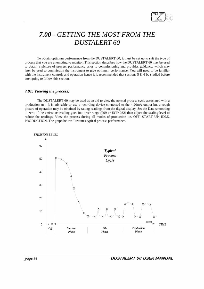
To obtain optimum performance from the DUSTALERT 60, it must be set up to suit the type of process that you are attempting to monitor. This section describes how the DUSTALERT 60 may be used to obtain a picture of process performance prior to commissioning and provides guidance, which may later be used to commission the instrument to give optimum performance. You will need to be familiar with the instrument controls and operation hence it is recommended that sections 5 & 6 be studied before attempting to follow this section.
7.01: Viewing the process; The DUSTALERT 60 may be used as an aid to view the normal process cycle associated with a production run. It is advisable to use a recording device connected to the 4-20mA output but a rough picture of operation may be obtained by taking readings from the digital display. Set the Data smoothing to zero; if the emissions reading goes into over-range (999 or ECD 032) then adjust the scaling level to reduce the readings. View the process during all modes of production i.e. OFF, START UP, IDLE, PRODUCTION. The graph below illustrates typical process performance.
X X X
X XX
X
X
X
XX X
X
X
X
X
X
X X
X X
X X
X X
X
TIME0
10
20
30
40
50
60
EMISSION LEVEL
TypicalProcessCycle
Start-upPhase
IdlePhase
ProductionPhase
Off
60f801

TA LUFT
ACCREDITED
DUSTALERT 60 USER MANUAL page 37
7.02: Hints for setting the Data smoothing; Generally the data smoothing should be set to a level at which the operator is confident of ‘seeing’ normal production. Individual pulses need not be seen unless required, but smoothing should not be such that a production run cannot be detected from background noise or idle modes. The graph below illustrates the effect of under-smoothing and over-smoothing.
UNDERDAMPEDSMOOTHING TOO LOW
SMOOTHING CORRECT
OVERDAMPEDSMOOTHING TOO HIGH

TA LUFT
ACCREDITED
page 38 DUSTALERT 60 USER MANUAL
7.03: Hints for setting the Alarm level and Alarm delay; The Alarm level is best set by comparing the levels for a ‘clean’ filter and a ‘dirty’ filter during operation. It is unlikely that obtaining this type of data will be practical in most cases and therefore the alarm level should be set just above normal process running conditions. The alarm delay function may be used to eliminate short duration high level pulses from triggering an alarm e.g. during startup many processes will have high-level emissions for a short period. By consideration of the graph below, it may be seen that the alarm level and delay may be set in two possible ways depending upon process dynamics. If the failure value is 10 times the reference level then the possibilities for the settings are: Alarm level = 5 Alarm delay = 1 minute. or Alarm level = 12 Alarm delay = 0 minutes. The first setting relies on the dust pulses being of uniform distribution whereby the second setting relies on the dust pulses being of uniform size.
Viewing of the process should give a good idea of how the alarms should be set to avoid problems during startup etc. In many cases, the optimum settings will be found by experimentation or trial and error methods.
7.04: Hints for setting the 4-20mA range; The 4-20mA range should be set such that a 20mA output is given some way above the alarm setting. This will allow ‘spikes’ exceeding the alarm level to be recorded and not ‘clipped’. For example, if the alarm level is set to 5, then the 4-20mA range should be set to 10. If the 4-20mA range is set too high, resolution of data will be lost, but if the 4-20mA range is set too low then data may be ‘clipped’ and lost. A safe ‘rule of thumb’ would be to set the 4-20mA range to approximately twice the alarm level.
1 2 3 4 5 6
6
12
(TIME)MINS
EMISSIONS
60f803

TA LUFT
ACCREDITED
DUSTALERT 60 USER MANUAL page 39

TA LUFT
ACCREDITED
page 40 DUSTALERT 60 USER MANUAL
APPENDIX A - INTERNAL JUMPER SETTINGS
A1: Disabling and enabling the SET key. A2: Fail-safe operation. A3: Setting latching or non-latching alarms. A4: The sensor sensitivity jumper. A5. Restart after Power Fail A6. Restoring Factory Settings

TA LUFT
ACCREDITED
DUSTALERT 60 USER MANUAL page 41
A1: Enabling and disabling the SET key;
For added security it is possible to disable the SET key on the front panel of the instrument by changing the position of an internal jumper link. This link is located at the bottom left-hand corner of the printed circuit board mounted inside the lid of the Control unit and has the legend ‘DIS/EN’ marked to its left. See the diagram below.
230
DIS/EN
DIS/EN
There are three pins and the jumper will link either the left pin to the centre pin or the right pin to the centre pin. The settings are as follows:
Jumper to the right pair – SET key enabled (Factory Setting). Jumper to the left pair – SET key disabled

TA LUFT
ACCREDITED
page 42 DUSTALERT 60 USER MANUAL
A2: Fail-safe operation; Alarm relay 1 is energised while power is applied to the DUSTALERT 60 thus it is possible to trigger an external alarm in the event of a power failure. (See section 3.05 for connection details). If no external alarm is to be used, it is possible to cause the DUSTALERT 60 to display an error message after a power failure when its power source is restored. This message will be displayed as error code 002, and the factory setting has this feature disabled. The function may be enabled by moving an internal jumper link located at the top edge of the main circuit board within the Control unit and is marked ‘PUP’. See diagram below for location details.
230
PUP
PUP
There are three pins and the jumper will link either the left pin to the centre pin or the right pin to the centre pin. The settings are as follows:
Jumper to the right pair – Power up alarm enabled. Jumper to the left pair - Power up alarm disabled (Factory Setting)

TA LUFT
ACCREDITED
DUSTALERT 60 USER MANUAL page 43
A3: Setting latching or non-latching alarms;
The DUSTALERT 60 has an internal jumper that may be used to control the action of the alarm relays. The relays may be set to either latching or non-latching by using the DTS jumper within the control unit. When the alarm relays are set to latching, the relays and alarm lamp will remain activated after an alarm event until the MUTE key is pressed. When the alarm relays are set to non-latching, the relays and alarm lamp will only be activated while the alarm condition is present. Error alarms will still latch the relay irrespective of the jumper setting. The figure below shows the positions of the DTS jumper for Non-latching and latching alarms.
Function Setting Meaning
Non-Latching Alarm relay will be relaxed when emission level falls below alarm level.
Not used Not used.
Latching Alarm relay will remain activated until the MUTE key is pressed.
Location of the DTS jumper inside the DUSTALERT 60 control unit.
ALF ALD DTS
CONTROL UNIT
DTS jumper
DTS

TA LUFT
ACCREDITED
page 44 DUSTALERT 60 USER MANUAL
A4: The Sensor Sensitivity Jumper; The sensor electronics contain a sensitivity adjustment. With the jumper removed, the sensitivity of the electronics is ‘high’. With the jumper link installed (shorting the two pins), the sensitivity is reduced to a ‘low’ value. This effectively reduces the amplification by a specific factor. NOTE: HIGH sensitivity should be used for applications where emissions are below about 1mg/M3
1234567
SENSOR UNIT(with lid removed)
SENSITIVITYJUMPER LINK
TA LUFT
ACCREDITED
DUSTALERT 60 USER MANUAL page 45
A5. Restart after Power Failure The instrument is designed to disregard short failures of its power supply. If the power supply is removed for a short period the instrument will resume operation as if nothing had happened. However, if the power failure persists, on the restoration of power the dynamic data in the filters is assumed to be unreliable and the filters will be reset.
A6. Restoring Factory Settings To restore the instrument’s factory setting, power downs the instrument for 1 minute then re-apply power while holding the SET and MUTE keys

TA LUFT
ACCREDITED
page 46 DUSTALERT 60 USER MANUAL
APPENDIX B - TABLES AND FACTORY SETTINGS
B1: Function settings & options table. B2: Error code table.
TA LUFT
ACCREDITED
DUSTALERT 60 USER MANUAL page 47
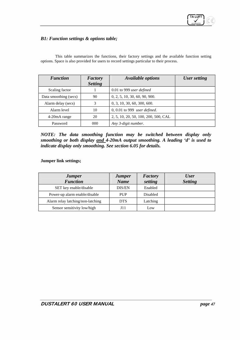
B1: Function settings & options table;
This table summarizes the functions, their factory settings and the available function setting options. Space is also provided for users to record settings particular to their process.
Function Factory Setting
Available options User setting
Scaling factor 1 0.01 to 999 user defined
Data smoothing (secs) 90 0, 2, 5, 10, 30, 60, 90, 900.
Alarm delay (secs) 3 0, 3, 10, 30, 60, 300, 600.
Alarm level 10 0, 0.01 to 999 user defined.
4-20mA range 20 2, 5, 10, 20, 50, 100, 200, 500, CAL
Password 000 Any 3-digit number. NOTE: The data smoothing function may be switched between display only smoothing or both display and 4-20mA output smoothing. A leading ‘d’ is used to indicate display only smoothing. See section 6.05 for details. Jumper link settings;
Jumper Function
Jumper Name
Factory setting
User Setting
SET key enable/disable DIS/EN Enabled
Power-up alarm enable/disable PUP Disabled
Alarm relay latching/non-latching DTS Latching
Sensor sensitivity low/high J11 Low

TA LUFT
ACCREDITED
page 48 DUSTALERT 60 USER MANUAL
B2: The ECD code table;
This table shows all of the available error codes for the DUSTALERT 60. See section 4.00 for a full description of error codes and how they are displayed. ECD Code Description Cause/Remedy
0 0 1
Emission alarm (Only with another error code active-i.e. compound code).
� High-level emission only when combined with another error code. For example, a high level emission may occur while ECD 2 is already showing, causing an ECD 3 to be displayed.
� Press the Mute Key to Clear.
0 0 2
Power failure.
� For fail-safe operation, the DUSTALERT 60 uses this ECD code to indicate that there has been an interruption to its power supply.
� May be disabled, see ‘Fail-safe operation’. � Press the MUTE key to cancel.
0 0 4
Beta Check Failure.
� A problem has occurred in the digital communications link between the control unit and the sensor unit.
� Carefully check the connections to the sensor cable at both the control unit and sensor head are correct.
� Carefully inspect the sensor cable for any signs of damage.
� Check that the in-line connector (where fitted) is secure and undamaged
� Press the MUTE key to cancel.
0 0 8
Alpha Check fail on power up.
� The DUSTALERT 60 has detected system integrity error.
� Press the MUTE button to clear. � If this fails press the SET and MUTE keys
together: NOTE - All settings including the reference will be reset to the factory defaults, please make a note of the settings before this activity.
� If the error still persists, consult us .
0 0 8
Alpha Check fail After trying to store a new setting or reference.
� The DUSTALERT 60 has detected a system integrity error.
� Press the MUTE button to clear, and then try again to change the setting or reference.
� If this fails, power down the instrument for 5 minutes then re-apply power while holding the SET and MUTE keys: NOTE - All settings including the reference will be reset to the factory defaults, please make a note of the settings before this activity.
� If this fails, consult us.

TA LUFT
ACCREDITED
DUSTALERT 60 USER MANUAL page 49
ECD codes continued… ECD Code Description Cause/Remedy
0 1 6 Reserved.
0 3 2
Over-range error.
� The DA60 is overloaded by a dust level that is too high.
� The Sensitivity may be set too high, adjust jumper in sensor.
� Press the MUTE key to clear. � See appendix A for details of the sensitivity
jumper.
0 6 4 Reserved.
1 2 8 Reserved.
TA LUFT
ACCREDITED
page 50 DUSTALERT 60 USER MANUAL
APPENDIX C - TROUBLESHOOTING & MAINTENANCE
C1: General maintenance. C2: Troubleshooting guide.

TA LUFT
ACCREDITED
DUSTALERT 60 USER MANUAL page 51
C1: General maintenance;
The DUSTALERT 60 is designed to require minimal maintenance, however the nature of many processes is such that a large build up of particulate may develop on the sensor rod. This build up will often have no effect whatsoever on the performance of the instrument but it is recommended that the build up be periodically removed. Some particulate, which may be moist or conductive by nature, may build up and cause a probe short circuit. If the probe rod should require cleaning, this may be performed by removing the sensor from the duct and thoroughly cleaning the entire rod, paying particular attention to the area near the PTFE insulator. The cleaning may be performed using wire wool, or for sticky or stubborn deposits, a cleaning agent such as natural blue has been found to be extremely effective. Always ensure that the probe rod is thoroughly dried before re-fitting to the ductwork. The following maintenance programme will ensure that the DUSTALERT 60 remains reliable throughout its life. The frequency of the maintenance programme is dependent upon the type of environment in which the instrument is to be used. It is recommended that the programme be followed 1 month after installation, then after 3, 6 or 12 monthly intervals as deemed necessary. Routine maintenance • Remove the sensor unit from the ductwork. • Thoroughly clean the probe rod and insulator as described above. • Clean off any excessive build up from the sensor enclosure using a stiff brush or damp cloth. • Check that the locknut and floating nut move freely. • Apply a small amount of copper slip or grease to the threads to prevent binding. • Re-fit the sensor unit to the ductwork. • Ensure that the sealed connectors are secure and undamaged. • Inspect the connecting cable (where possible), ensure that it is not damaged or stressed. • Wipe the face panel of the control unit with a damp cloth (do not use cleaning agents). • Set the Data smoothing to zero. • Watch the instrument performance with the process running and ensure that the process is still being
followed correctly. Note that the instrument will follow all plant activity with the data smoothing set to zero, hence the readings will fluctuate considerably.
• If necessary, follow the set-up procedure to re-set the scaling. • Restore the data smoothing to its previous setting. This completes the routine maintenance programme.
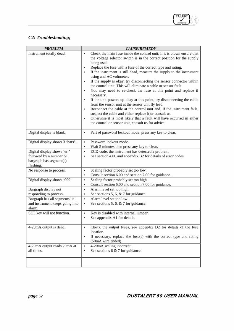
TA LUFT
ACCREDITED
page 52 DUSTALERT 60 USER MANUAL
C2: Troubleshooting;
PROBLEM CAUSE/REMEDY Instrument totally dead. � Check the main fuse inside the control unit; if it is blown ensure that
the voltage selector switch is in the correct position for the supply being used.
� Replace the fuse with a fuse of the correct type and rating. � If the instrument is still dead, measure the supply to the instrument
using and AC voltmeter. � If the supply is okay, try disconnecting the sensor connector within
the control unit. This will eliminate a cable or sensor fault. � You may need to re-check the fuse at this point and replace if
necessary. � If the unit powers-up okay at this point, try disconnecting the cable
from the sensor unit at the sensor unit fly lead. � Reconnect the cable at the control unit end. If the instrument fails,
suspect the cable and either replace it or consult us. � Otherwise it is most likely that a fault will have occurred in either
the control or sensor unit, consult us for advice.
Digital display is blank. � Part of password lockout mode, press any key to clear.
Digital display shows 3 ‘bars’. � Password lockout mode. � Wait 5 minutes then press any key to clear.
Digital display shows ‘err’ followed by a number or bargraph has segment(s) flashing.
� ECD code, the instrument has detected a problem. � See section 4.00 and appendix B2 for details of error codes.
No response to process. � Scaling factor probably set too low. � Consult section 6.00 and section 7.00 for guidance.
Digital display shows ‘999’ � Scaling factor probably set too high. � Consult section 6.00 and section 7.00 for guidance.
Bargraph display not responding to process.
� Alarm level set too high. � See sections 5, 6, & 7 for guidance.
Bargraph has all segments lit and instrument keeps going into alarm.
� Alarm level set too low. � See sections 5, 6, & 7 for guidance.
SET key will not function. � Key is disabled with internal jumper. � See appendix A1 for details.
4-20mA output is dead.
� Check the output fuses, see appendix D2 for details of the fuse location.
� If necessary, replace the fuse(s) with the correct type and rating (50mA wire ended).
4-20mA output reads 20mA at all times.
� 4-20mA scaling incorrect. � See sections 6 & 7 for guidance.

TA LUFT
ACCREDITED
DUSTALERT 60 USER MANUAL page 53

TA LUFT
ACCREDITED
page 54 DUSTALERT 60 USER MANUAL
APPENDIX D - SYSTEM ELECTRICAL DETAILS
D1: Cable preparation details. D2: 4-20mA output fuse location. D3: Control unit connection diagram. D4: Sensor unit connection diagram.

TA LUFT
ACCREDITED
DUSTALERT 60 USER MANUAL page 55
D1: Cable preparation details;
The DUSTALERT 60 is supplied with 10M of 8 core screened signal cable that will have to be prepared for connection to the control and sensor units. The cable should be prepared for connection to the control unit in accordance with the following diagram. Failure to comply with the suggested preparation may lead to reduced EMC immunity and hence poor performance from the instrument.
50mm
5mm
Strip 5mm of insulation from each core.
6mm eyelet
Remove 50mm of the outer sheath.
Join black & screen into a 6mm eyelet.
Black core
Screen

TA LUFT
ACCREDITED
page 56 DUSTALERT 60 USER MANUAL
D2: The 4-20mA output fuse location;
NOTE: This section refers only to instruments fitted with the optional 4-20mA output. The 4-20mA output is protected by two 50mA wire ended fuses mounted in sockets. The location of the fuses is shown in the diagram below.
230
4-20mA OUTPUT FUSES
To replace the fuses, unplug the existing fuse by pulling upwards then trim the legs of the replacement to the correct length and insert it into the socket.

TA LUFT
ACCREDITED
DUSTALERT 60 USER MANUAL page 57
D3: Control unit connection diagram;
TITL
E
12
34
56
7
-12V
TX-
RX-
RX+
TX+
+12V
NCCO
MNO
12
31
23
NE
L
SUPP
LY
FUSE
T160
mA
4-20
mA
OUTP
UT(o
ptio
n)
SUPP
LYVO
LTAG
ESE
LECT
OR
Seco
ndar
y Fus
es
Type
TR5
wi
re en
ded
T2.5AT630mAT800mAT800mA
SUPPLY LIVESUPPLY EARTH
SUPPLY NEUTRAL
4-20mA RETURN4-20mA OUTPUT
230
NCCO
MNO
12
3
VIOLET & WHITERED
BLUENOT CONNECTED
GREENYELLOWBROWN
BLACK &SCREEN
RELA
Y 1
RELA
Y 2
DA60
Mai
n W
iring
Instr
uctio
n
DA60-x Standard Violet & White----------V & W Blue------------------------Red Red-------------------------Blue Not Connected-----------N/C Yellow---------------------Green Green----------------------Yellow Brown Brown

TA LUFT
ACCREDITED
page 58
DU
STALER
T 60 USER
MA
NU
AL
D
4: Sensor unit connection diagram;
1234567
SENSOR UNIT(with lid removed)
VIOLET & WHITEBLUE
REDNOT CONNECTED
YELLOWGREEN
BROWN
BLACK & SCREEN
FromControl
Unit
NOTE:Black and screenmust be connectedtogether and fitted
to the eyeletprovided.
Sensor Wiring instruction

TA LUFT
ACCREDITED
DUSTALERT 60 USER MANUAL page 59

TA LUFT
ACCREDITED
page 60 DUSTALERT 60 USER MANUAL
APPENDIX E - SUPPORT DOCUMENTATION • Product data sheet • Installation note

TA LUFT
ACCREDITED
DUSTALERT 60 USER MANUAL page 61
INDEX 4-20mA output
Fuse location............................................. 55 4-20mA range
Help for setting ......................................... 37 Setting of................................................... 33
Air purge....................................................... 10 Alarm
Connecting................................................ 15 Contact rating......................................... 15
Alarm delay Help for setting ......................................... 37
Alarm Delay Setting of................................................... 29
Alarm factor Explanation of........................................... 21
Alarm Factor Setting of................................................... 30
Alarms Latching .................................................... 42 Non-latching ............................................. 42
Data Smoothing Help for setting ......................................... 36 Setting of................................................... 28 Types of .................................................... 28
Display mode................................................ 23 DTS jumper .................................................. 42 Edit mode...................................................... 23 Emission factor
Explanation of........................................... 21 Error codes
Multiple .................................................... 18 Overview .................................................. 17
Factory settings............................................. 46 Fail-safe ........................................................ 41 Fault finding ................................................. 51
Floating nut .............................................. 8, 10 Insulator ......................................................... 8 Locknut......................................................... 10 Mains supply
Connecting................................................ 14 Maintenance
Routine ..................................................... 50 MUTE key
Function of................................................ 22 Output
4-20mA connecting................................... 14 Alarm contact............................................ 15
Password Acceptance................................................ 24 Changing of .............................................. 25 Entry ......................................................... 23 Lockout..................................................... 24 Wrong entry.............................................. 24
Problem solving............................................ 51 Process
Viewing of ................................................ 35 PUP............................................................... 41 scaling factor................................................. 27 SEL key
Function of................................................ 22 Sensitivity
Changing of .............................................. 43 Sensor
Connections .............................................. 10 To control ................................................. 13
SET key Disabling/Enabling ................................... 40 Function of................................................ 22
TriboACE® .................................................... 7 Troubleshooting............................................ 51