operating instructions - tjvega.com.cn · operating instructions vegacom 557 siemens 3964 and 3964...
TRANSCRIPT

in out
Level and Pressure
Operating InstructionsVEGACOM 557Siemens 3964 and 3964 R procedurewith RK 512
on
557
BA
PC

2 VEGACOM 557 Siemens
Contents
Contents
Safety information ........................................................................ 2
Note Ex area ................................................................................ 2
1 Product description
1.1 Application ............................................................................ 4
1.2 Configuration ........................................................................ 4
1.3 Function ................................................................................. 4
1.4 Complete measuring system with digitalcommunication and networking .......................................... 6
1.5 Technical data ....................................................................... 7
1.6 Dimensions ........................................................................... 9
2 Mounting and electrical connection
2.1 Mounting instructions ......................................................... 10
2.2 Potential stages and galvanic separation ........................ 11
2.3 Electrical connection .......................................................... 11
Safety informationPlease read this manual carefully, and also takenote of country-specific installation standards(e.g. the VDE regulations in Germany) as wellas all prevailing safety regulations and acci-dent prevention rules.
For safety and warranty reasons, any internalwork on the instruments, apart from that in-volved in normal installation and electrical con-nection, must be carried out only by qualifiedVEGA personnel.
Note Ex areaPlease note the approval documents (yellowbinder), and especially the included safetydata sheet.

VEGACOM 557 Siemens 3
Contents
3 Addressing of the process signals
3.1 Switch adjustments on VEGACOM 557 ........................... 12
3.2 Settings on the CP 524 ...................................................... 14
4 Setup
4.1 Check list ............................................................................ 16
4.2 Parameter setting CP 524 ................................................. 16
5 S5 functional component
5.1 Synchron order .................................................................. 22
5.2 Handling components for reading in of data(indicating values) ............................................................. 23
5.3 Reading in data (indicating values) .................................. 25
6 Supplement
6.1 Short description of the standard interfacesRS 232, RS 422 and RS 485 ............................................. 33
6.2 Complete overview on process image ofmeasured values in VEGACOM ....................................... 36

4 VEGACOM 557 Siemens
Product description
1 Product description
1.1 Application
With VEGACOM 557 an efficient interfaceconverter (Gateway) is available. It is usedfor VEGA specific protocols of the DISBUSand LOGBUS into standard data formats.
The existing version is used for connection oflevel and pressure measuring systems toPLC systems with Siemens communicationprocessors CP 524 and CP 525. The proce-dures 3964 and 3964 R are supported.
This conversion of the protocol formats ena-bles to call up measured data and statusinformation of the measuring systems viaPLC/DCS. This bidirectional data traffic re-quires respective measures on the PLC/DCSside which are described in this instruction.
The data received in the PLC can be furtherprocessed by the user program, i.e. forexample visualised or used for control pur-poses.
In a planned further stage, signal condition-ing instrument-specific parameters can beoutputted, modified and returned.
PCinterface
VEGACOM 557 connections
DISBUS
Siemens 3964
and 3964 R
Supply
Basic board Add. board
1.2 Configuration
The component VEGACOM 557 is designedin 19" technology with 5 TE width (1 TE =5.08 mm) acc. to DIN 41 494. It can be used:- in carrier BGT 596- in VEGALOG 571 carrier BGT LOG 571- in housing type 505.
The electrical connection is made via a plugconnector acc. to DIN 41 612 on the rear ofthe component. The connection to LOGBUSis made via an additional 5-pole plug connec-tor mounted to the DIN plug connector.
A 9-pole SUB-D plug marked "PC" is locatedin the front plate of VEGACOM 557. It is usedfor connection of a PC to VEGACOM 557 viaRS 232 C.
The component consists of two boards:- the basic board- the additional board.
The basic board contains the power supplyunit, the PC interface, the DISBUS/LOGBUSinterface as well as the connections for theModbus.
The additional board is screwed to the basicboard and includes the Siemens 3964 and3964 R interface.
additional plugconnector forLOGBUS

VEGACOM 557 Siemens 5
Product description
DISBUS
LOGBUS
CP524/CP525
Function VEGACOM 557
Buffermemory
Proc-essimage
Trans-mis-sionmemory
Testconver-sion
1.3 Function
DISBUS
The new generation of VEGAMET 500 signalconditioning instruments can transfer meas-ured data and status information via theDISBUS to VEGADIS 174 indicating instru-ments.
VEGACOM 557 receives as participants onthe DISBUS these data in a DCS telegram.The telegrams are written in VEGACOM 557into a buffer memory.
LOGBUS
Data are permanently exchanged on theLOGBUS between the individual componentsof VEGALOG 571. VEGACOM 557 receivesas participant of this LOGBUS the part of thetelegrams containing the measured valuesand status information.
Communication process
The data communication between VEGACOM557 and the communication processorCP 524/525 is only made if initiated by thePLC which can call up the requested informa-tion via special commands. The data fromDISBUS/LOGBUS are first written in a buffermemory in VEGACOM 557.
From this buffer memory, the data set istransferred into a process image. The protec-tion converter software enquires the individualstorage section cyclically for the saved val-ues. The data sets are tested and convertedinto the Siemens 3964 or 3964 R data format.After this conversion, the data are transferredinto the transmission memory and furthertransferred to the communication processor.There, they are read in via a S5 PLC func-tional component and saved in a data compo-nent for further processing.
The D-SUB plug in the front plate ofVEGACOM 557 is used for connection of aPC. In conjunction with the indicating andadjustment software VEGA Visual Operating(VVO) configuration and parameter setting ofthe VEGAMET signal processing instrumentsor the VEGALOG processing system arepossible. In addition measured values andfailure messages can be shown graphicallyvia the visualisation software Visual VEGA(VV).
In a planned level, Simatic S5 can additionallycall up beside measured data and statusinformation also parameters from VEGAMET/VEGALOG, receive them, if necessary modifythem and return them. This strategy enablesthe control of level measurement and processpressure measuring systems via processingsystems.
Connection VEGACOM 557 on DISBUS
Connection VEGACOM 557 on LOGBUS
DISBUS
LOGBUS
SimaticS5
CP524/525
1 ………… 15VEGAMET
VEGACOM 557with additionalboard S5
Proce-dure
3964 /RInstru-ment
interface
RS 232/RS485/RS 422/TTY
SimaticS5
CP524/525
Procedure3964 R
Instru-ment
interface
RS 232/RS485/RS 422/TTY
VEGACOM 557 withadditional board S5
VEGALOG571 CPU

6 VEGACOM 557 Siemens
onVEGAMET
513
!
ESC OK
- +100%
CONNECT
onVEGAMET
513
!
ESC OK
- +100%
CONNECT
onVEGAMET
513
!
ESC OK
- +100%
CONNECT
onVEGAMET
513
!
ESC OK
- +100%
CONNECT
onVEGAMET
513
!
ESC OK
- +100%
CONNECT
onVEGAMET
513
!
ESC OK
- +100%
CONNECT
onVEGAMET
513
!
ESC OK
- +100%
CONNECT
onVEGAMET
513
!
ESC OK
- +100%
CONNECT
on
on
PC
VEGALOG571
!
1
4
43
5
5
1 2
VVOPC
VEGACOM557
!
BA
on
VV
1.4 Complete measuring system with digital communication andnetworking
DISBUS
LOGBUS
Modbus system
Measuring system with digital communication and networking
Product description
Explanation:
1 VEGA Visual Operating (VVO)Adjustment software for the PC for theuser-friendly configuration and parameteradjustment of VEGA instruments- VEGALOG 571 directly via RS 232
connection cable on the CPU card orVEGACOM 557
- several VEGAMET via VEGACOM 557or individually via VEGACONNECT
- VEGASON, VEGAPULS viaVEGACONNECT on the signal cable oron the sensor
2 Visual VEGA (VV)PC visualisation software for presentationof measurement data from VEGA instru-ments in a graphical or tabular form. Inte-gration of individual measurement loopsinto groups, saving of fault signals andmeasured values (recorder function).Suitable for networks
3 VEGACOM 557Interface converter for conversion of VEGAspecific protocol into standard data for-mats. Suitable for connection to theDISBUS output of VEGAMET series 500/600 signal conditioning instruments or theLOGBUS of VEGALOG 571 processingsystem.
4 VEGACONNECT 2Connection cable (interface converter)between VEGA instruments (VEGASON,VEGAPULS or VEGAMET) and a PC inconjunction with the adjustment softwareVEGA Visual Operating.
5 RS 232 connection cable (interlink cable)Connection cable between PC andVEGALOG 571-CPU or VEGACOM 557

VEGACOM 557 Siemens 7
1.5 Technical data
Power supply
Operating voltage Unom = 24 V AC (20 … 53 V), 50/60 Hz or= 24 V DC (20 … 72 V)
Power consumption approx. 6 VA or approx. 4 WFuse 1 A, slow-blowGalvanic separation up to 4 kV
Meas. data input DISBUS
Data transmission DISBUS (digital data transmission)Connection cable 2-wire unscreened (standard cable)Cable length max. 1000 mGalvanic separation up to 0.5 kV
Meas. data input LOGBUS
Data transmission LOGBUS (digital data transmission)Connection cable connection via BUS plugGalvanic separation up to 0.5 kV
PC interface
Interface standard RS 232 CCable length max. 15 m (up to 9600 baud)Connection cable 3-wire, if necessary screenedTransmission rate 300, 600, 1200, 2400, 4800, 9600, 19200 Bit/sTransmission format 8 data bits, 1 stop bit, even/no parityGalvanic separation up to 0.5 kV
Data output to CP 524/CP 525
Interfaces RS 232 RS 422 RS 485Cable length 15 m 1200 m 1200 mConnection cable 3-wire 5-wire 3-wire
twisted in pairs, with braiding andmetal housing plug
Transmission mode serially asynchronous, half-duplexBackup BCCCoding system 8 bit binaryNumber of bits 1 start bit, 8 data bits, 1 parity bit, 1 stop bitTransmission rate 110, 300; 600; 1200; 2400; 4800; 9600;
19200 baudGalvanic separation from the power supply and data input
Electrical connection
Power supplyMeas. data inputs multiple plug acc. to DIN 41 612, series F,
48-pole, d, b, zPC interface D-SUB plug connector, 9-pole pin in
front plate
Product description
8 VEGACOM 557 Siemens
Product description
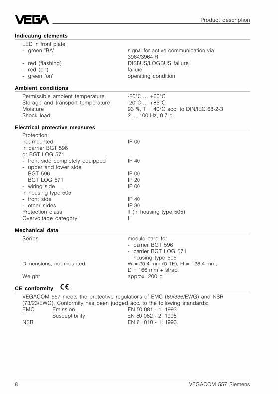
Indicating elements
LED in front plate- green "BA" signal for active communication via
3964/3964 R- red (flashing) DISBUS/LOGBUS failure- red (on) failure- green "on" operating condition
Ambient conditions
Permissible ambient temperature -20°C … +60°CStorage and transport temperature -20°C … +85°CMoisture 93 %, T = 40°C acc. to DIN/IEC 68-2-3Shock load 2 … 100 Hz, 0.7 g
Electrical protective measures
Protection:not mounted IP 00in carrier BGT 596or BGT LOG 571- front side completely equipped IP 40- upper and lower side
BGT 596 IP 00BGT LOG 571 IP 20
- wiring side IP 00in housing type 505- front side IP 40- other sides IP 30Protection class II (in housing type 505)Overvoltage category II
Mechanical data
Series module card for- carrier BGT 596- carrier BGT LOG 571- housing type 505
Dimensions, not mounted W = 25.4 mm (5 TE), H = 128.4 mm,D = 166 mm + strap
Weight approx. 200 g
CE conformity
VEGACOM 557 meets the protective regulations of EMC (89/336/EWG) and NSR(73/23/EWG). Conformity has been judged acc. to the following standards:EMC Emission EN 50 081 - 1: 1993
Susceptibility EN 50 082 - 2: 1995NSR EN 61 010 - 1: 1993

VEGACOM 557 Siemens 9
1625,5
15
100
on
557
BA
128,
4
25,4
5 TECircuit board 100 x 160 x 1.5European size
Multiple plug
LOGBUSplug
front RS 232C interface (PC)
1.6 Dimensions
Product description
Front plate with- 9-pole D-SUB plug- LED green BA (operating condition)- LED red fault signal- LED green operating voltage
10 VEGACOM 557 Siemens
d b z
1a c
3c3
c11
a27
5
7
9
15
17
19
21
23
25
27
11
13
29
31
VEGALOG card
Interface card
VEGACOM 557
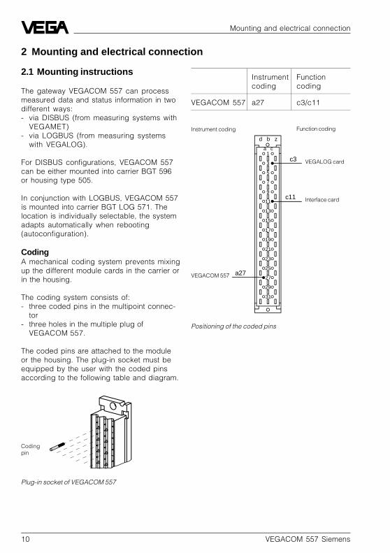
2.1 Mounting instructions
The gateway VEGACOM 557 can processmeasured data and status information in twodifferent ways:- via DISBUS (from measuring systems with
VEGAMET)- via LOGBUS (from measuring systems
with VEGALOG).
For DISBUS configurations, VEGACOM 557can be either mounted into carrier BGT 596or housing type 505.
In conjunction with LOGBUS, VEGACOM 557is mounted into carrier BGT LOG 571. Thelocation is individually selectable, the systemadapts automatically when rebooting(autoconfiguration).
CodingA mechanical coding system prevents mixingup the different module cards in the carrier orin the housing.
The coding system consists of:- three coded pins in the multipoint connec-
tor- three holes in the multiple plug of
VEGACOM 557.
The coded pins are attached to the moduleor the housing. The plug-in socket must beequipped by the user with the coded pinsaccording to the following table and diagram.
Instrument coding Function coding
Codingpin
Plug-in socket of VEGACOM 557
Positioning of the coded pins
Mounting and electrical connection
Instrument Functioncoding coding
VEGACOM 557 a27 c3/c11
2 Mounting and electrical connection

VEGACOM 557 Siemens 11
Pin Description I/O
1 CTS clear to send I2 RxD receive data I3 TxD transmit data O4 RTS request to send O5 GND ground –
Note:• VEGACOM 557 operates without hardware
handshake, i.e. RTS and CTS are notwired.
P1 P2
P4
P3
2
2 / 5
3 … 5
4
Mounting and electrical connection
2.2 Potential stages and galvanic separation
2.3 Electrical connection
Multiple plug (rear)
DISBUS not used withVEGALOG)
2 N (-)
d b z
2 L1 (+)
16
18
18
20
20
22
24
28
30
30
32
32
+
–
Supply voltage
D-SUB plug (front plate)
Power supply unit
DISBUS /LOGBUS
RS232C
MicrocontrollerField bus controller
Siemens S5
P1 … P4: Potential stages
R+ RxD
T+ TxD
TTY RS 232 RS 485 RS 422
GND GND GND GND
DATA RXTX
TTY RS 232 RS 485 RS 422
GND GND GND GND
123
6
789
5
4
R–
T–
/DATA /RX/TX
RS 232
CTSRxDTxDRTSGND
12 VEGACOM 557 Siemens
1 2 3 4 5 6 7 8 1 2 3 4 5 6 7 8 1 2 3 4 5 6 7 8
Multiple plugBasic board
Bottom view of VEGACOM 557
DIL switchbasic board
Frontplate
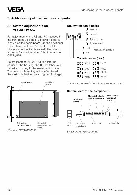
DIL switch blocksadditional boardAdditional
board 2 11 2 3
Hook switchadditionalboard
1
ON EDG
2 3 4 5 6
even parity
DIL switch basic board
no parity
Transmission rate (baud)
300
600
1200
2400
4800
9600
19200
137.5
On
Off
1. instrument
2. instrument
2 3 4
ON
1
Additionalboard
DIL switchon basic board
DIL switchbelow additionalboard
Basic board
Side view of VEGACOM 557
3 Addressing of the process signals
Adjustment possibilities for DIL switch on basic board
Addressing of the process signals
3.1 Switch adjustments onVEGACOM 557
For adjustment of the RS 232 PC interface inthe front panel, a 6-pole DIL switch block islocated on the basic board. On the additionalboard there are three 6-pole DIL switchblocks as well as two hook switches whichare used for configuration of the interface toCP524/525.
Before inserting VEGACOM 557 into thecarrier or the housing, the DIL switches mustbe set according to the user-specific data.The data of this setting will be effective withthe next initialisation (switching on of voltage).
Modem initialisation
Bottom view of the component:

VEGACOM 557 Siemens 13
DIL switch 1 additional board
Selection of the interfaceSW 8 SW 7 SW 6
ON OFF OFF RS 232
OFF ON OFF RS 422, RS 485
OFF OFF ON TTY
Bus termination for RS 485, RS 422SW 5 SW4
ON ON bus termination ON
OFF OFF bus termination OFF
Selection of the protocolSW 3 SW 2 SW 1
OFF OFF OFF free
OFF OFF ON free
OFF ON OFF free
OFF ON ON free
ON OFF OFF free
ON OFF ON (ASCII)
ON ON OFF Siemens 3964,3964 R
ON ON ON (MODBUS RTU/ ASCII)
L RL R
12
1 2 3
Hook switch
= Activation of the TTY interface
= Activation of the RS 232 interface (factory setting)
Note:L = position left, R = position right
Top view to the removed additional board
Assignment of the switch positions (hook switch onadditional board)
DIL switch
L RL R
12
L RL R
12
Addressing of the process signals
Additional board bottom view:
Hook switch additional board:
The hook switches enable the selection be-tween RS 232 and TTY interface

14 VEGACOM 557 Siemens
1ONEPG
23456781ONEPG
2345678 1ONEPG
2345678
DIL switch 3 additional board(negligible)
Switch position (factory setting)Procedure Siemens 3964 RData transmission 9600 baudNumber of data bits 8Parity evenphysical interface RS 232
DIL switch DIL switch DIL switch1 2 3
3.2 Settings on the CP 524
Interface number
The interface number is required in the S5program for addressing of the communicationprocessor and can be set with J53. As astandard feature all bridges are closed (inter-face number = 0).
CP instrument interface
3 instrument interfaces are available. AnRS 232, a TTY and a RS 422 / 485 interfacemodule. Depending on the interface used inthe CP, the assignment of the connections onVEGACOM 557 (see multiple plug) must betaken into consideration and the setting of theDIL switches must be made on theVEGACOM additional board.
Addressing of the process signals
DIL switch 2 additional board
Selection of the baud rateSW 8 SW 7 SW 6
OFF OFF OFF 300 Baud
ON OFF OFF 600 Baud
OFF ON OFF 1200 Baud
ON ON OFF 2400 Baud
OFF OFF ON 4800 Baud
ON OFF ON 9600 Baud
OFF ON ON 19200 Baud
ON ON ON 38400 Baud
Number of data bitsSW 5
ON 8 data bits
OFF 7 data bits
ParitySW 4 SW 3
OFF OFF without parity
OFF ON without parity
ON OFF odd parity (ODD)
ON ON even parity (EVEN)
Protocol modeSW 2
OFF Siemens 3964
ON Siemens 3964 R
DCS measured value imageSW 1
OFF all measured values MET1all measured values MET2
ON 1 measured value MET 11 measured value MET 2
VEGACOM 557 Siemens 15
CP 524
+24V 16R+ 13R- 14
GND 24-24V 12
T+ 10t- 19
GND 21
COM 557
z18 R+d20 R- d18 T+z20 T-
CP 524
Rx 4
/Rx 11 Tx 2/Tx 9
GND 8
COM 557
d30 Rx
d32 /Rx z30 Txz32 /Tx
d28 GND
CP 524
Rx 4/Rx 11 Tx 2
/Tx 9
GND 8
COM 557
d30 Rxd32 /Rx z30 Tx
z32 /Tx
d28 GND
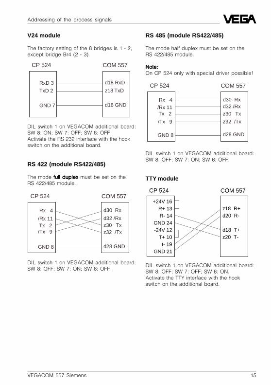
DIL switch 1 on VEGACOM additional board:SW 8: OFF; SW 7: ON; SW 6: OFF.
Addressing of the process signals
CP 524
RxD 3
TxD 2
GND 7
COM 557
d18 RxD
z18 TxD
d16 GND
DIL switch 1 on VEGACOM additional board:SW 8: ON; SW 7: OFF; SW 6: OFF.Activate the RS 232 interface with the hookswitch on the additional board.
RS 422 (module RS422/485)
The mode full duplexfull duplexfull duplexfull duplexfull duplex must be set on theRS 422/485 module.
V24 module
The factory setting of the 8 bridges is 1 - 2,except bridge Br4 (2 - 3).
RS 485 (module RS422/485)
The mode half duplex must be set on theRS 422/485 module.
Note:Note:Note:Note:Note:On CP 524 only with special driver possible!
DIL switch 1 on VEGACOM additional board:SW 8: OFF; SW 7: ON; SW 6: OFF.
TTY module
DIL switch 1 on VEGACOM additional board:SW 8: OFF; SW 7: OFF; SW 6: ON.Activate the TTY interface with the hookswitch on the additional board.

16 VEGACOM 557 Siemens
Setup
4 Setup
4.1 Check list
The check list gives a short overview on the activities required for configuration. A detaileddescription of the individual items is made in this document.
• Equip VEGACOM 557 with the additional board S5 (for communication with procedure3964 /R).
• Equip communication processor CP with the necessary interface (RS232, RS422/485 orTTY). Set interface number
• Adjust VEGACOM DIL switches and hook switches. Interface parameters must be adjusted.Make sure that the same interface is selected which is used on the CP.
• Connect CP to VEGACOM.• Create a program for configuration of the CP with the programming package COM 525.• Load the created program with an EPROM programming device to the EPROM module.• Insert the EPROM module into the memory shaft of the communication processor.• A SYNCHRON order must be called up in the organisation components OB 20,21 and 22 for
synchronisation of the CP with the S5 application.• Integrate FETCH and RECEIVE calls in the S5 user program to read in indicating values of
VEGAMET or VEGALOG in data component 3.
4.2 Parameter setting CP 524
For communication with Simatic S5 via procedure 3964 R / 3964, VEGACOM supports theFetch function (fetch data). This function can be called up by the PLC function block to read inthe indicating values and save them in data component 3.
Before the Fetch function can be applied, the parameter setting for the communication proces-sor CP must be done. For this purpose, the S5 programming package COM 525 is available.
The parameter setting of the following points is pattern-controlled so that no programmingknowledge is necessary. The created program is loaded with an EPROM programming de-vice (PROMMER) to the EPROM module. The module is inserted in the memory module shaftof the CP.
After calling up the programming package COM 525 in the S5 program in menu Change/further… (directory: \STEP 5) the following points must be processed:
ActivityActivityActivityActivityActivity PurposePurposePurposePurposePurpose
Basic pattern Creating of a new CP program
Fetch order Definition and determination of orders where data (indicating values) aresaved
Procedure Activate procedure 3964 R and set transmission parameters
Interpreter Activate, to process communication orders

VEGACOM 557 Siemens 17
Setup
Basic pattern
To create a new program, you have to enter the file and system name in the basic pattern. Ascomponent, you have to choose RK (for computer link).
BASIC PATTERN –> SIMATIC S5 / COM 525 P R O G R A M C H O I C E
DRIVE: CPROGRAM NAME: PROGR 1COMPONENTE: RK
System name: systemCreator: tgrCreation date: 03.11.94
PG Datue - Time: T M J H M08.11.94 - 10:42
F1 | F2 | F3 | F4 | F5 | F6 | F7 | F8| | | | | | |
CHOICE | | | | | | HELP | EXIT
F1 for additional choice:
BASIC PATTERN -> PROGRAM CHOICE -> SIMATIC S5 / COM 525 C H O I C E—————————————————————————————————————
DRIVE: CPROGRAM NAME: PROGR 1COMPONENTE: RK
System name: systemCreator: tgrCreation date: 03.11.94
F1 | F2 | F3 | F4 | F5 | F6 | F7 | F8USER DATA| TRANS- | | | | | |PROGRAM. | MIT | DELETE | INFO |COMPRESS. |CONTINUE | | EXIT

18 VEGACOM 557 Siemens
Order indicating values
After F1 selection (see previous pattern) the adjustment of the order number is expected,here e.g. 1. For parameter setting of order number 1, function key F5 (Order Progr.) must beselected:In this pattern it will be determined that order no. 1 is a Fetch order (fetch data). The data tobe received should be fetched by source data component 3 from source word address 0.Coordination markers are not required.
-> CHOICE -> ORDER BLOCK -> SIMATIC S5 / COM 525 O R D E R P R O G R .————————————————————————————————————— DRIVE: C PROGRAM: PROGR1 COMPONENT: RK
O R D E R
Order - no: 001
Order: FETCH
Order - Type Data component
CPU - no: 1
DB - no: 003
Source - word adress: 00000 D 0000 H
Optionally with coorindation - tag: .
F1 | F2 | F3 | F4 | F5 | F6 | F7 | F8TO | BACK- | FOR- | | DELETE |TAKE OVER | |
PRINTER | WARDS | WARD | | ORDER |ORDER | HELP | EXIT
Setup

VEGACOM 557 Siemens 19
Setup
Order switching condition relay
The relays are saved in data component DB5. Therefore it is necessary to enter this datacomponent in the order. The order number has been set to 2 as we assumed that already anorder for reading the measured values is available.
-> CHOICE -> ORDER BLOCK -> SIMATIC S5 / COM 525 O R D E R P R O G R .————————————————————————————————————— DRIVE: C PROGRAM: PROGR1 COMPONENT: RK
O R D E R
Order - no: 002
Order: FETCH
Order - Type Data component
CPU - no: 1
DB - no: 005
Source - word adress: 00000 D 0000 H
Optionally with coorindation - tag: .
F1 | F2 | F3 | F4 | F5 | F6 | F7 | F8TO | BACK- | FOR- | | DELETE |TAKE OVER | |
PRINTER | WARDS | WARD | | ORDER |ORDER | HELP | EXIT
Procedure
For determination of the procedure with the transmission parameters, the procedure compo-nents can be taken over out of the programming library COMLIB02.
Change to the transmission menu: Basic pattern F1 -> Choice F2 -> Transfer F5 -> FD-FD.The menu appears:
-> PROGRAM CHOICE -> CHOICE-> SIMATIC S5 / COM 525 T R A N S M I T —————————————————————————————————————
Source: Destination:
VOLUME: FD FDDRIVE: C CINTERFACE NO.:PROGRAM NAME: COMLIB02 PROGR1COMPONENT: RK
System name: STANDARD LIBRARY xCreator: GW Karlsruhe xCreation date: 23.06.88 08.11.94
F1 | F2 | F3 | F4 | F5 | F6 | F7 | F8| | INTER- | | PRINT | ORDER | || | PRETER |PROCEDURE | PARAM. | BLOCK | HELP | EXIT

20 VEGACOM 557 Siemens
Setup
Select with F7 in the field program name the program library COMLIB02. Push F4 to select theprocedure:
-> PROGRAM CHOICE -> CHOICE-> TRANSMIT –> SIMATIC S5 / COM 525 P R O C E D U R E —————————————————————————————————————
Source: Destination:
VOLUME: FD FDDRIVE: C CINTERFACE NO.:PROGRAM NAME: COMLIB02 PROGR1COMPONENT: RK
Source: COMPONENT NAME VERSIONRK P3964R 01
F1 | F2 | F3 | F4 | F5 | F6 | F7 | F8TRANS- | | | | | | |MIT | | | | | | HELP | EXIT
Select with F7 in the field component the procedure 3964 R and transfer with F1 to the own file(here PROGR1 ).Procedure transmission parameter.Change to the parameter menu: Basic pattern F1 -> Choice F2 -> F6 Continue F2 Procedureparameter. The character length must be set to 8, the number of stop bits to 1 and the parity toEVEN.
Interpreter
The interpreter component can be taken over from the program library COMLIB02 to load theinterpreter RK512. Change to the transmission menu: Basic pattern F1 -> Choice F2 -> Trans-fer F5 -> FD-FD. The menu appears:
-> PROGRAM CHOICE -> CHOICE-> SIMATIC S5 / COM 525 T R A N S M I T —————————————————————————————————————
Source: Destination:
VOLUME: FD FDDRIVE: C CINTERFACE NO.:PROGRAM NAME: COMLIB02 PROGR1COMPONENT: RK
System name: STANDARD LIBRARY xCreator: GW Karlsruhe xCreation date: 23.06.88 08.11.94
F1 | F2 | F3 | F4 | F5 | F6 | F7 | F8| | INTER- | | PRINT | ORDER | || | PRETER |PROCEDURE | PARAM. | BLOCK | HELP | EXIT

VEGACOM 557 Siemens 21
Setup
Select with F7 in the field program name the programming library COMLIB02. For interpreterselection push F3:
-> PROGRAM CHOICE -> CHOICE-> TRANSMIT –> SIMATIC S5 / COM 525 P R O C E D U R E —————————————————————————————————————
Source: Destination:
VOLUME: FD FDDRIVE: C CINTERFACE NO.:PROGRAM NAME: COMLIB02 PROGR1COMPONENT: RK
Source: COMPONENT NAME VERSIONRK RK512 01
F1 | F2 | F3 | F4 | F5 | F6 | F7 | F8TRANS- | | | | | | |MIT | | | | | | HELP | EXIT
Issue short description
To check the settings, a short description can be issued.Change to the overview menu: Basic pattern F1 -> Selection F4 -> Information F3 -> FD F2 ->Short description. The menu appears:
-> PROGRAM CHOICE -> CHOICE-> SIMATIC S5 / COM 525 INFO —————————————————————————————————————
VOLUME: FDDRIVE: CPROGRAM NAME: PROGR1COMPONENT: RK
System name: systemCreator: tgrCreation date: 03.11.94
Data type Element name Number Data type NumberInterpreter: RK512 01 1 Order block 1Procedure: P3964R 01 1Print param: DRUCK_PARA
Total number: 3 elementsProgram length: 9321 words
F1 | F2 | F3 | F4 | F5 | F6 | F7 | F8SHORT | | | | ORDER | | |DESCR. | | | | BLOCK | | HELP | EXIT
The interpreter must be set to RK512 and the procedure to P3964R.
Save programm in EPROMThe program is transferred with an EPROM programming device (PROMMER) to the EPROMmemory module for the CP. For this, you have the program PROM 525. It is called up in the S5program in directory Change/further... (directory: \STEP 5).

22 VEGACOM 557 Siemens
S5 functional component
5 S5 functional component
For the STEP 5 user program, internal functional components (HTB handling components)HTB SYNCHRON, HTB FETCH and HTB RECEIVE are required. To call up the internal functioncomponents, these must be loaded first from the automation device AG S5. The menu selec-tion is then as follows: Object > Components > Transfer > AG file.
5.1 Synchron order
After the starting-up phase, the CP expects a SYNCHRON order. This is necessary for thehandling of the FETCH / SEND orders. The SYNCHRON component is generally called up withthe STEP 5 user program in the organisation components OB20, OB21 and OB22.
Calling up of handling components SYNCHRON
SPA FB 249 with Simatic S5-115U CPU 942 B
Para- Format Meaningmeter
SSNR KY Interface numberKY = 0,y y = 0 … 255The logical number of the interface on which the concerned order can befound.See switch position on CP (J53).
BLGR KY Block sizeKY = 0,y y=1,2,3,4, 5 for block size 16,32,64, 128 and 256 Bytes.
PAFE BY Error indication with parameter setting failureBY = MB 0, … MB 255; AB 0, …, AB 127Information of a byte, in which a parameter setting failure is entered
Example:
Call up in OB20. Also valid for OB21 and OB22
OB 20C:CP524_ST.S5D LAE=11Network 1 0000 Output :SPA FB 249Name :SYNCHRONSSNR : KY 0,0BLGR : KY 0,4 Block size 128PAFE : MB 50 Parameter failure in tag byte 50 :BE

VEGACOM 557 Siemens 23
S5 functional component
5.2 Handling components for reading in of data (indicating values)
For reading in the indicating values from the VEGAMET instruments and saving them in a PLCdata component, the handling component HTB FETCH is necessary to place orders and theHTB RECEIVE to fetch and save data.
Handling component FETCH
The FETCH component gives the order to the CP to fetch data of a communication partner. Thereceipt of the data however is carried out by the component RECEIVE.
Calling up of handling component FETCH
SPA FB 246 with Simatic S5-115U CPU 942 B
Para- Format Meaningmeter
SSNR KY Interface numberKY = 0,y y = 0 … 255The logical number of the interface on which the concerned order can befound.See switch position on CP (J53).
A-NR KY Order numberKY = 0,y y = 0 … 255 y = order number
ANZW W AnzeigewortW= DBx , MWx x = 0 … 255 Addresse of the double word (4 bytes !!)In the double word, the processing status of a certain order is shown
ZTYP KC Type of the data destination
DBNR KY Data component numberKY = 0,y y = 0 … 255Number of the data component in which the data should be saved
ZANF KF Initial data block address of the destination
ZLAE KF,KH Data block length of the destination
PAFE Error indication with parameter setting failureBY = MB 0, … MB 255; AB 0, …, AB 127Information of a byte, in which a parameter setting failure is entered

24 VEGACOM 557 Siemens
S5 functional component
Handling component RECEIVE
This component receives the data of the stated order number.
Difference is made between the two function modes:• RECEIVE -All
data can be received for each individual order. The parameters ZTYP, DBNR, ZANF andZLAE are then irrelevant
• RECEIVE-Directdata are received for a certain order
Call: Handling component RECEIVE
SPA FB 245 with Simatic S5-115U CPU 942 B
Para- Format Meaningmeter
SSNR KY Interface numberKY = 0,y y = 0 … 255The logical number of the interface on which the concerned order can befound.See switch position on CP (J53).
A-NR KY Order numberKY = 0,y y = 0 … 255 direct parameter setting
y = 0 RECEIVE-All
ANZW W Indicating wordW= DBx , MWx x = 0 … 255 Address of the double word (4 bytes !!)In the double word, the processing status of a certain order is shown
ZTYP KC Information irrelevant as destination information was determined in FETCH
DBNR KY Information irrelevant as destination information was determined in FETCH
ZANF KF Information irrelevant as destination information was determined in FETCH
ZLAE KF,KH Information irrelevant as destination information was determined in FETCH
PAFE Error indication with parameter setting failureBY = MB 0, … MB 255; AB 0, …, AB 127Information of a byte, in which a parameter setting failure is entered
Note:The RECEIVE component communicates with the CP only if the linking result VKE is 1 beforecalling up the component. This can be forced with the instruction
O M 1.1ON M 1.1.
VEGACOM 557 Siemens 25
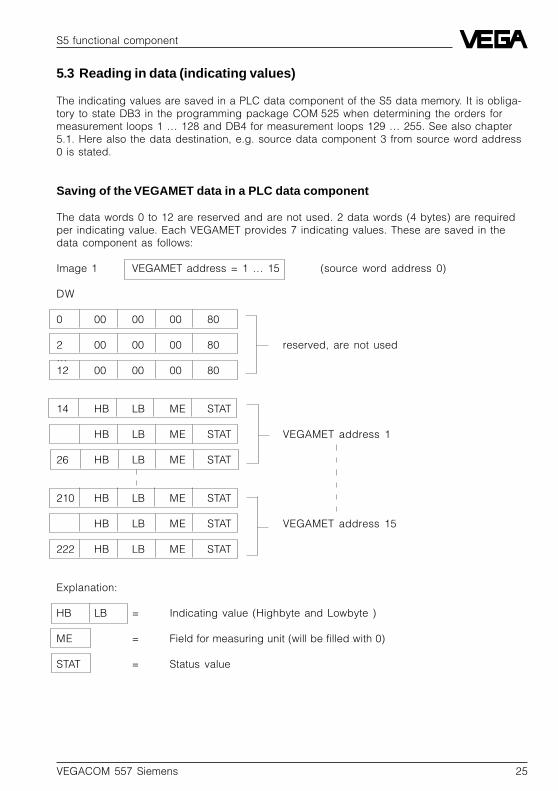
5.3 Reading in data (indicating values)
The indicating values are saved in a PLC data component of the S5 data memory. It is obliga-tory to state DB3 in the programming package COM 525 when determining the orders formeasurement loops 1 … 128 and DB4 for measurement loops 129 … 255. See also chapter5.1. Here also the data destination, e.g. source data component 3 from source word address0 is stated.
Saving of the VEGAMET data in a PLC data component
The data words 0 to 12 are reserved and are not used. 2 data words (4 bytes) are requiredper indicating value. Each VEGAMET provides 7 indicating values. These are saved in thedata component as follows:
Image 1 VEGAMET address = 1 … 15 (source word address 0)
DW
0 00 00 00 80
2 00 00 00 80 reserved, are not used…12 00 00 00 80
14 HB LB ME STAT
HB LB ME STAT VEGAMET address 1
26 HB LB ME STAT
210 HB LB ME STAT
HB LB ME STAT VEGAMET address 15
222 HB LB ME STAT
Explanation:
HB LB = Indicating value (Highbyte and Lowbyte )
ME = Field for measuring unit (will be filled with 0)
STAT = Status value
S5 functional component

26 VEGACOM 557 Siemens
Status values:
STAT Meaning
00 H Valid value
01 H Simulated value
80 H Value not available
FF H General error
Calculation of the data word address
The data word address of the first indicating value of VEGAMET to address is determined asfollows:
Data word address = VEGAMET address • 14 + ZANF (Fetch)for the parameter ZANF from Fetch order ZANF (Fetch) = 0 results from:
VEGAMET (DISBUS): Data word address = VEGAMET address • 14 – Source word address • 2
for VEGAMET address = 1...15
Saving of the relay information from VEGAMET out of data component 5
Data word 0 is reserved. One data word will be reserved per VEGAMET. In total 15 + 1 arecovered by VEGAMET.
DW VEGAMET address
0 reserved
1 1
2 2
3 3
4 4
… …
15 15
Contents of the data words: Bits
15 14 13 12 11 10 9 8 7 6 5 4 3 2 1 0
Status reser- reser- reser- reser- reser- Relay Relay Relay Relay Relay Relay Relay Relay Relay Rel.ved ved ved ved ved 10 9 8 7 6 5 4 3 2 1
Status = 0 –> Relay information is validStatus = 1 –> Relay information is invalid.
S5 functional component

VEGACOM 557 Siemens 27
Saving of VEGALOG data in a PLC data component
2 data words (4 bytes) are required per indicating value. These are saved in the PLC datacomponent DB as follows:
Image 2 VEGALOG functional component no. = 1 … 254 (source word address 0)
DW
0 HB LB ME STAT VEGALOG functional component no. 1
2 HB LB ME STAT VEGALOG functional component no. 2
4 HB LB ME STAT VEGALOG functional component no. 3
248 HB LB ME STAT
250 HB LB ME STAT
252 HB LB ME STAT VEGALOG functional component no. 127
Note: For indicating values > 64 a second enquiry must be started(64 • 4 = 256, see block size for Synchron order)
Explanation:
HB LB = Indicating value (Highbyte and Lowbyte)
ME = Field for measuring unit (will be filled with 0)
STAT = Status value
Status values:
STAT Meaning
00 H Valid value
01 H Simulated value
80 H Value not available
FF H General error
S5 functional component

28 VEGACOM 557 Siemens
Saving of the relay information from VEGALOG out of data component
1 data word will be reserved per LOGBUS card. In total, 32 data words will be covered byVEGALOG.
DW Card address
0 1
1 2
2 3
3 4
4 5
… …
31 32
Contents of the data words: Bits
15 14 13 12 11 10 9 8 7 6 5 4 3 2 1 0
Status reser- reser- reser- reser- reser- Relay Relay Relay Relay Relay Relay Relay Relay Relay Rel.ved ved ved ved ved 10 9 8 7 6 5 4 3 2 1
Status = 0 –> Relay information is validStatus = 1 –> Relay information is invalid.
Parameter setting of the FETCH component
ZLAE is an important parameter, indicating the length of the data block. The value is depend-ent on the number of indicating values:
VEGAMET (DISBUS): ZLAE value = 14 + VEGAMET module no. • 14VEGALOG (LOGBUS): ZLAE value = number of indicating values • 2
SSNR: The interface number corresponds to the switch position in the CP (standard feature= 0)
A-NR: The order number corresponds to the setting in the programming package COM525
ANW: Statement of a double marker word for status descriptionZTYP: KC DB Data destination is data componentDBNR: KY 0 Data component numberZANF: KF +0 Initial word in DB is data word 0. With != 0 the data sector is shifted by
this value.ZLAE : KF +value data length in bytes value = see abovePAFE : Statement of a marker byte for indication of parameter setting failures
S5 functional component

VEGACOM 557 Siemens 29
S5 functional component
Parameter setting of the RECEIVE component
The information on the data destination, parameter : ZTYP, DBNR, ZANF and ZLAE are irrel-evant as this information was already defined in the programming package COM 525 with theorder determination.
SSNR: The interface number corresponds to the switch positions in the CP.(standard feature = 0)
A-NR: The order number corresponds to the setting in the programming package COM525
ANW: Statement of a double marker word for status descriptionZTYP: KC DB Data destination is data componentDBNR: KY 0,0 Data component number, here irrelevantZANF: KF +0 Initial word in DB, here irrelevantZLAE: KF +0 Data length in bytes, here irrelevantPAFE: Statement of a marker byte for indication of parameter setting failures
Application example for VEGAMET
Call up in OB20, OB21 and OB22
OB 20C:CP524_ST.S5D LAE=11Network 1 0000 Output :SPA FB 249Name :SYNCHRONSSNR : KY 0,0BLGR : KY 0,3 Block size 64PAFE : MB 50 Parameter error in merker byte 50 :BE

30 VEGACOM 557 Siemens
S5 functional component
Call up of the Fetch and Receive component for the indicating values
The program reads in the indicating values for the VEGAMET instruments (DISBUS) orVEGALOG instruments (LOGBUS). The Fetch order was determined in the programmingpackage COM 525 with order number 1. The statements on the data destination had beencarried out in the programming package with the order determination. Therefore the destina-tion parameters ZTYP, DBNR, ZANF and ZLAE are negligible when calling up the RECEIVEcomponent.
FB 1 C:CP524_ST.S5D LAE = 62Network 1 0000 OutputName :TEST
:O M 1.1 :ON M 1.1 VKE = 1 force, so that FETCH
: is worked on in any case:
:SPA FB 246 enquire FETCH-componentName :FETCHSSNR : KY 0,0 Interface no. = 0A-NR : KY 0,1 Order number = 1ANZW : MW 10 Indication double word up from MW10ZTYP : KC DB Data destination (of indication values) in data componentDBNR : KY 0,3 ... number 3ZANF : KF +0 Data destination to DW0ZLAE : KF +42* fetch 6 indication values (of 2 signal conditioning instruments
VEGAMET 1 and 2)PAFE : MB 2 Parametr. failure in MB 2 : : : : : : : :O M 1.1 :ON M 1.1 VKE = 1 force, so that FETCH : is worked on in any case : :SPA FB 245 enquire RECEIVE-componentName :RECEIVESSNR : KY 0,0 Interface no. = 0A-NR : KY 0,0 Order number = 1ANZW : MW 12 Indication double word up from MW12ZTYP : KC DB Data destination in data componentDBNR : KY 0,0ZANF : KF +0ZLAE : KF +0PAFE : MB 3 : : : : : : :BE
* 6DW as offset (see page 23), 6DW for VEGAMET 1, 6DW for VEGAMET 2

VEGACOM 557 Siemens 31
S5 functional component
Call up of the Fetch and Receive component for the relay information
...FB 2 C:CP524_ST.S5D LAE = 62Network 1 0000 OutputName :REL
:O M 1.1 :ON M 1.1 VKE = 1 force, so that FETCH
: is worked on in any case:
:SPA FB 246 enquire FETCH-componentName :FETCHSSNR : KY 0,0 Interface no. = 0A-NR : KY 0,2 Order number = 2 for relay informationANZW : MW 11 Indication double word up from MW11ZTYP : KC DB Data destination(the indication values) in data componentDBNR : KY 0,4 ... Number 3ZANF : KF +0 Data destination to DW0ZLAE : KF +32 32 words (all relays)PAFE : MB 4 Parametr.failure in MB 4 : : : : : : : :O M 1.1 :ON M 1.1 VKE = 1 force, so that FETCH : is worked on in any case : :SPA FB 245 enquire RECEIVE-componentName :RECEIVESSNR : KY 0,0 Interface no. = 0A-NR : KY 0,0 Order number = 1ANZW : MW 12 Indication double word up from MW12ZTYP : KC DB Data destination in data componentDBNR : KY 0,0ZANF : KF +0ZLAE : KF +0PAFE : MB 3 : : : : : : :BE
Note:In the total program only one RECEIVE necessary.

32 VEGACOM 557 Siemens
S5 functional component
Saving of the VEGAMET data in the PLC data component
Data wordDW
0 00 00 00 807 pieces
2 00 00 00 80 reserved, are not used
12 00 00 00 80
14 HB LB ME STAT7 pieces
16 HB LB ME STAT VEGAMET address 1
18 HB LB ME STAT
20 HB LB ME STAT7 pieces
22 HB LB ME STAT VEGAMET address 2
24 HB LB ME STAT
up to 40
Saving of the VEGALOG data into PLC data component
Data wordDW
0 HB LB ME STAT DCS 1
2 HB LB ME STAT DCS 2
4 HB LB ME STAT DCS 3
6 HB LB ME STAT DCS
8 HB LB ME STAT DCS 5
10 HB LB ME STAT DCS 6
up to 40 up to DCS 21
Explanation:
HB LB = Indicating value (Highbyte and Lowbyte )
ME = Field for measuring unit (will be filled with 0)
STAT = Status value
VEGACOM 557 Siemens 33
Supplement
6 Supplement
6.1 Short description of the stand-ard interfaces RS 232, RS 422and RS 485
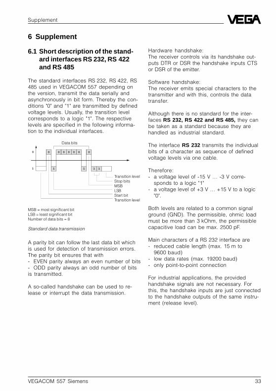
The standard interfaces RS 232, RS 422, RS485 used in VEGACOM 557 depending onthe version, transmit the data serially andasynchronously in bit form. Thereby the con-ditions "0" and "1" are transmitted by definedvoltage levels. Usually, the transition levelcorresponds to a logic "1". The respectivelevels are specified in the following informa-tion to the individual interfaces.
Standard data transmission
0 0 0 0 0 0 0
1 1 1 1
0
1
Data bits
Transition levelStop bitsMSBLSBStart bitTransition level
MSB = most significant bitLSB = least significant bitNumber of data bits = 8
A parity bit can follow the last data bit whichis used for detection of transmission errors.The parity bit ensures that with- EVEN parity always an even number of bits- ODD parity always an odd number of bitsis transmitted.
A so-called handshake can be used to re-lease or interrupt the data transmission.
Hardware handshake:The receiver controls via its handshake out-puts DTR or DSR the handshake inputs CTSor DSR of the emitter.
Software handshake:The receiver emits special characters to thetransmitter and with this, controls the datatransfer.
Although there is no standard for the inter-faces RS 232, RS 422 and RS 485, they canbe taken as a standard because they arehandled as industrial standard.
The interface RS 232 transmits the individualbits of a character as sequence of definedvoltage levels via one cable.
Therefore:- a voltage level of -15 V … -3 V corre-
sponds to a logic "1"- a voltage level of +3 V … +15 V to a logic
"0".
Both levels are related to a common signalground (GND). The permissible, ohmic loadmust be more than 3 kOhm, the permissiblecapacitive load can be max. 2500 pF.
Main characters of a RS 232 interface are- reduced cable length (max. 15 m to
9600 baud)- low data rates (max. 19200 baud)- only point-to-point connection
For industrial applications, the providedhandshake signals are not necessary. Forthis, the handshake inputs are just connectedto the handshake outputs of the same instru-ment (release level).

34 VEGACOM 557 Siemens
The interface RS 422 transfers the data asvoltage difference between two correspond-ing cables. Signal earth as grounding is notrequired. One pair of wires is required for thetransmitting as well as for the receipt signal,consisting of an inverted and a non-invertedsignal cable. Possible common-mode inter-ferences cause a symmetric shift of the volt-age level and cannot deteriorate the usefulsignal.
Thanks to the higher interference immunitycompared to RS 232, distances up to 1200 mand high data rates up to 10 Mbits can bereached. The interference immunity is alsovisible on the permissible voltage levels: withan output level of the transmitter under loadof ±2 V the receiver components accept alevel of ±200 mV still as valid signal.
Special feature of the RS 422 is that it allowsthe unidirectional connection of up to 10 re-ceivers on one transmitter. With higher trans-mission rates and/or large distances, atermination (adaption of the wave resistance)is necessary and a galvanic separation of thetransmitter/receiver components is absolutelyrecommended.
The interface RS 485 means an extension ofthe RS 422 concept to a bus-compatiblesystem, whereby the physical differencesare neglicible.
The bus system can include up to 32 partici-pants, i.e. 1 master and 31 slaves. A protocolensures that at any time max. one participantis active as transmitter, whereas the othersare switched passively. For transmission andreceipt only one cable pair is required, whichis used in alternate cycle. With 10 Mbits/s asdata rate and 1200 m as max. distance, thedata correspond to these of the RS 422 inter-face.
Supplement
To be neutral against (inevitable for largedistances) potential shifts, a galvanic isolationof the transmission/receipt component isrecommended. A termination is generallynecessary, independent on data rate anddistance.
Partly also interfaces TTY (also called 20 mAor Current Loop) are used. The data aretransmitted by switching on and off a currentof 20 mA in a cable loop in the cycle of thedata bits. This interface however is not sub-jected to a standardisation so that the usemust be projected in detail. With galvanicseparation, distances up to 1000 m with datarates of 300 … 9600 baud can be transmittedsafely.
Conclusion
Main features for interfaces acc. to RS 232are:- reduced cable lengths- low data rates- only point-to-point connection
Main features for interfaces acc. to RS 422and RS 485 are:- large cable lengths- high data rates- basis for bus systems

VEGACOM 557 Siemens 35
Supplement
Table: Comparison of important interface data
Interfaces RS 232 C RS 422 A RS 485Transmission asym. symmetr. symmetr.Number of drivers 1 1 32Number of receivers 1 10 32Transmission distance 15 m 1200 m 1200 mmax. transmission rate 20 KBit/s 10 MBit/s 10 MBit/s
EmitterPermissible driveroutput voltage ±25 V –0.25…6 V –7…12 VDriver output signal- without load ±15 V ± 5 V ± 5 V- with load ± 5 V ± 2 V ±1.5 VDriver load 3…7 kOhm 100 Ohm 54 Ohm
ReceiverInput voltage ±15 V ±7 V –7…12 VSensitivity ±3 V ±200 mV ±200 mVInput resistance 3…7 kOhm 4 kOhm 12 kOhm
10km
1,2km1km
100m
30m15m
100 1k 10k 20k 100k 1M Bit/s 10M
RS 422-ARS 485
RS 232-C
Dis
tanc
e
Transmission rate
Diagram: Distance –– Transmission rate

36 VEGACOM 557 Siemens
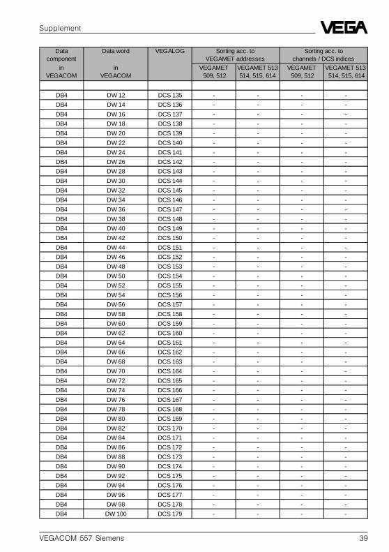
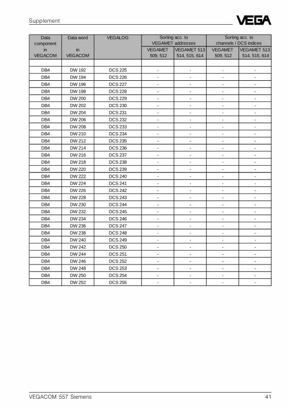
6.2 Complete overview on process image of measured values in VEGACOM
Data component
Data word VEGALOG
in VEGACOMin
VEGACOMVEGAMET 509, 512
VEGAMET 513 514, 515, 614
VEGAMET 509, 512
VEGAMET 513514, 515, 614
DB3 DW 0 DCS 1 - - - -
DB3 DW 2 DCS 2 - - CH1 MET1 DCS1 MET1
DB3 DW 4 DCS 3 - - CH1 MET2 DCS1 MET2
DB3 DW 6 DCS 4 MET1 CH1 - CH1 MET3 DCS1 MET3
DB3 DW 8 DCS 5 MET1 CH2 - CH1 MET4 DCS1 MET4
DB3 DW 10 DCS 6 MET1 CH3 - CH1 MET5 DCS1 MET5
DB3 DW 12 DCS 7 MET2 CH1 - CH1 MET6 DCS1 MET6
DB3 DW 14 DCS 8 MET2 CH2 MET1 DCS1 CH1 MET7 DCS1 MET7
DB3 DW 16 DCS 9 MET2 CH3 MET1 DCS2 CH1 MET8 DCS1 MET8
DB3 DW 18 DCS 10 MET3 CH1 MET1 DCS3 CH1 MET9 DCS1 MET9
DB3 DW 20 DCS 11 MET3 CH2 MET1 DCS4 CH1 MET10 DCS1 MET10
DB3 DW 22 DCS 12 MET3 CH3 MET1 DCS5 CH1 MET11 DCS1 MET11
DB3 DW 24 DCS 13 MET4 CH1 MET1 DCS6 CH1 MET12 DCS1 MET12
DB3 DW 26 DCS 14 MET4 CH2 MET1 DCS7 CH1 MET13 DCS1 MET13
DB3 DW 28 DCS 15 MET4 CH3 MET2 DCS1 CH1 MET14 DCS1 MET14
DB3 DW 30 DCS 16 MET5 CH1 MET2 DCS2 CH1 MET15 DCS1 MET15
DB3 DW 32 DCS 17 MET5 CH2 MET2 DCS3 CH2 MET1 -
DB3 DW 34 DCS 18 MET5 CH3 MET2 DCS4 CH2 MET2 DCS2 MET1
DB3 DW 36 DCS 19 MET6 CH1 MET2 DCS5 CH2 MET3 DCS2 MET2
DB3 DW 38 DCS 20 MET6 CH2 MET2 DCS6 CH2 MET4 DCS2 MET3
DB3 DW 40 DCS 21 MET6 CH3 MET2 DCS7 CH2 MET5 DCS2 MET4
DB3 DW 42 DCS 22 MET7 CH1 MET3 DCS1 CH2 MET6 DCS2 MET5
DB3 DW 44 DCS 23 MET7 CH2 MET3 DCS2 CH2 MET7 DCS2 MET6
DB3 DW 46 DCS 24 MET7 CH3 MET3 DCS3 CH2 MET8 DCS2 MET7
DB3 DW 48 DCS 25 MET8 CH1 MET3 DCS4 CH2 MET9 DCS2 MET8
DB3 DW 50 DCS 26 MET8 CH2 MET3 DCS5 CH2 MET10 DCS2 MET9
DB3 DW 52 DCS 27 MET8 CH3 MET3 DCS6 CH2 MET11 DCS2 MET10
DB3 DW 54 DCS 28 MET9 CH1 MET3 DCS7 CH2 MET12 DCS2 MET11
DB3 DW 56 DCS 29 MET9 CH2 MET4 DCS1 CH2 MET13 DCS2 MET12
DB3 DW 58 DCS 30 MET9 CH3 MET4 DCS2 CH2 MET14 DCS2 MET13
DB3 DW 60 DCS 31 MET10 CH1 MET4 DCS3 CH2 MET15 DCS2 MET14
DB3 DW 62 DCS 32 MET10 CH2 MET4 DCS4 CH3 MET1 DCS2 MET15
DB3 DW 64 DCS 33 MET10 CH3 MET4 DCS5 CH3 MET2 -
DB3 DW 66 DCS 34 MET11 CH1 MET4 DCS6 CH3 MET3 DCS3 MET1
DB3 DW 68 DCS 35 MET11 CH2 MET4 DCS7 CH3 MET4 DCS3 MET2
DB3 DW 70 DCS 36 MET11 CH3 MET5 DCS1 CH3 MET5 DCS3 MET3
DB3 DW 72 DCS 37 MET12 CH1 MET5 DCS2 CH3 MET6 DCS3 MET4
DB3 DW 74 DCS 38 MET12 CH2 MET5 DCS3 CH3 MET7 DCS3 MET5
DB3 DW 76 DCS 39 MET12 CH3 MET5 DCS4 CH3 MET8 DCS3 MET6
DB3 DW 78 DCS 40 MET13 CH1 MET5 DCS5 CH3 MET9 DCS3 MET7
DB3 DW 80 DCS 41 MET13 CH2 MET5 DCS6 CH3 MET10 DCS3 MET8
DB3 DW 82 DCS 42 MET13 CH3 MET5 DCS7 CH3 MET11 DCS3 MET9
DB3 DW 84 DCS 43 MET14 CH1 MET6 DCS1 CH3 MET12 DCS3 MET10
DB3 DW 86 DCS 44 MET14 CH2 MET6 DCS2 CH3 MET13 DCS3 MET11
Sorting acc. to VEGAMET addresses
Sorting acc. tochannels / DCS indices
Supplement

VEGACOM 557 Siemens 37
Data component
Data word VEGALOG
in VEGACOM
in VEGACOM
VEGAMET 509, 512
VEGAMET 513514, 515, 614
VEGAMET 509, 512
VEGAMET 513514, 515, 614
DB3 DW 88 DCS 45 MET14 CH3 MET6 DCS3 CH3 MET14 DCS3 MET12
DB3 DW 90 DCS 46 MET15 CH1 MET6 DCS4 CH3 MET15 DCS3 MET13
DB3 DW 92 DCS 47 MET15 CH2 MET6 DCS5 - DCS3 MET14
DB3 DW 94 DCS 48 MET15 CH3 MET6 DCS6 - DCS3 MET15
DB3 DW 96 DCS 49 - MET6 DCS7 - -
DB3 DW 98 DCS 50 - MET7 DCS1 - DCS4 MET1
DB3 DW 100 DCS 51 - MET7 DCS2 - DCS4 MET2
DB3 DW 102 DCS 52 - MET7 DCS3 - DCS4 MET3
DB3 DW 104 DCS 53 - MET7 DCS4 - DCS4 MET4
DB3 DW 106 DCS 54 - MET7 DCS5 - DCS4 MET5
DB3 DW 108 DCS 55 - MET7 DCS6 - DCS4 MET6
DB3 DW 110 DCS 56 - MET7 DCS7 - DCS4 MET7
DB3 DW 112 DCS 57 - MET8 DCS1 - DCS4 MET8
DB3 DW 114 DCS 58 - MET8 DCS2 - DCS4 MET9
DB3 DW 116 DCS 59 - MET8 DCS3 - DCS4 MET10
DB3 DW 118 DCS 60 - MET8 DCS4 - DCS4 MET11
DB3 DW 120 DCS 61 - MET8 DCS5 - DCS4 MET12
DB3 DW 122 DCS 62 - MET8 DCS6 - DCS4 MET13
DB3 DW 124 DCS 63 - MET8 DCS7 - DCS4 MET14
DB3 DW 126 DCS 64 - MET9 DCS1 - DCS4 MET15
DB3 DW 128 DCS 65 - MET9 DCS2 - -
DB3 DW 130 DCS 66 - MET9 DCS3 - DCS5 MET1
DB3 DW 132 DCS 67 - MET9 DCS4 - DCS5 MET2
DB3 DW 134 DCS 68 - MET9 DCS5 - DCS5 MET3
DB3 DW 136 DCS 69 - MET9 DCS6 - DCS5 MET4
DB3 DW 138 DCS 70 - MET9 DCS7 - DCS5 MET5
DB3 DW 140 DCS 71 - MET10 DCS1 - DCS5 MET6
DB3 DW 142 DCS 72 - MET10 DCS2 - DCS5 MET7
DB3 DW 144 DCS 73 - MET10 DCS3 - DCS5 MET8
DB3 DW 146 DCS 74 - MET10 DCS4 - DCS5 MET9
DB3 DW 148 DCS 75 - MET10 DCS5 - DCS5 MET10
DB3 DW 150 DCS 76 - MET10 DCS6 - DCS5 MET11
DB3 DW 152 DCS 77 - MET10 DCS7 - DCS5 MET12
DB3 DW 154 DCS 78 - MET11 DCS1 - DCS5 MET13
DB3 DW 156 DCS 79 - MET11 DCS2 - DCS5 MET14
DB3 DW 158 DCS 80 - MET11 DCS3 - DCS5 MET15
DB3 DW 160 DCS 81 - MET11 DCS4 - -
DB3 DW 162 DCS 82 - MET11 DCS5 - DCS6 MET1
DB3 DW 164 DCS 83 - MET11 DCS6 - DCS6 MET2
DB3 DW 166 DCS 84 - MET11 DCS7 - DCS6 MET3
DB3 DW 168 DCS 85 - MET12 DCS1 - DCS6 MET4
DB3 DW 170 DCS 86 - MET12 DCS2 - DCS6 MET5
DB3 DW 172 DCS 87 - MET12 DCS3 - DCS6 MET6
DB3 DW 174 DCS 88 - MET12 DCS4 - DCS6 MET7
DB3 DW 176 DCS 89 - MET12 DCS5 - DCS6 MET8
Sorting acc. to VEGAMET addresses
Sorting acc. to channels / DCS indices
Supplement

38 VEGACOM 557 Siemens
Data component
Data word VEGALOG
in VEGACOM
in VEGACOM
VEGAMET 509, 512
VEGAMET 513, 514, 515, 614
VEGAMET 509, 512
VEGAMET 513514, 515, 614
DB3 DW 178 DCS 90 - MET12 DCS6 - DCS6 MET9
DB3 DW 180 DCS 91 - MET12 DCS7 - DCS6 MET10
DB3 DW 182 DCS 92 - MET13 DCS1 - DCS6 MET11
DB3 DW 184 DCS 93 - MET13 DCS2 - DCS6 MET12
DB3 DW 186 DCS 94 - MET13 DCS3 - DCS6 MET13
DB3 DW 188 DCS 95 - MET13 DCS4 - DCS6 MET14
DB3 DW 190 DCS 96 - MET13 DCS5 - DCS6 MET15
DB3 DW 192 DCS 97 - MET13 DCS6 - -
DB3 DW 194 DCS 98 - MET13 DCS7 - DCS7 MET1
DB3 DW 196 DCS 99 - MET14 DCS1 - DCS7 MET2
DB3 DW 198 DCS 100 - MET14 DCS2 - DCS7 MET3
DB3 DW 200 DCS 101 - MET14 DCS3 - DCS7 MET4
DB3 DW 202 DCS 102 - MET14 DCS4 - DCS7 MET5
DB3 DW 204 DCS 103 - MET14 DCS5 - DCS7 MET6
DB3 DW 206 DCS 104 - MET14 DCS6 - DCS7 MET7
DB3 DW 208 DCS 105 - MET14 DCS7 - DCS7 MET8
DB3 DW 210 DCS 106 - MET15 DCS1 - DCS7 MET9
DB3 DW 212 DCS 107 - MET15 DCS2 - DCS7 MET10
DB3 DW 214 DCS 108 - MET15 DCS3 - DCS7 MET11
DB3 DW 216 DCS 109 - MET15 DCS4 - DCS7 MET12
DB3 DW 218 DCS 110 - MET15 DCS5 - DCS7 MET13
DB3 DW 220 DCS 111 - MET15 DCS6 - DCS7 MET14
DB3 DW 222 DCS 112 - MET15 DCS7 - DCS7 MET15
DB3 DW 224 DCS 113 - - - -
DB3 DW 226 DCS 114 - - - -
DB3 DW 228 DCS 115 - - - -
DB3 DW 230 DCS 116 - - - -
DB3 DW 232 DCS 117 - - - -
DB3 DW 234 DCS 118 - - - -
DB3 DW 236 DCS 119 - - - -
DB3 DW 238 DCS 120 - - - -
DB3 DW 240 DCS 121 - - - -
DB3 DW 242 DCS 122 - - - -
DB3 DW 244 DCS 123 - - - -
DB3 DW 246 DCS 124 - - - -
DB3 DW 248 DCS 125 - - - -
DB3 DW 250 DCS 126 - - - -
DB3 DW 252 DCS 127 - - - -
DB3 DW 254 DCS 128 - - - -
DB4 DW 0 DCS 129 - - - -
DB4 DW 2 DCS 130 - - - -
DB4 DW 4 DCS 131 - - - -
DB4 DW 6 DCS 132 - - - -
DB4 DW 8 DCS 133 - - - -
DB4 DW 10 DCS 134 - - - -
Sorting acc. to VEGAMET addresses
Sorting acc. to channels / DCS indices
Supplement
VEGACOM 557 Siemens 39
Data component
Data word VEGALOG
in VEGACOM
in VEGACOM
VEGAMET 509, 512
VEGAMET 513514, 515, 614
VEGAMET 509, 512
VEGAMET 513 514, 515, 614
DB4 DW 12 DCS 135 - - - -
DB4 DW 14 DCS 136 - - - -
DB4 DW 16 DCS 137 - - - -
DB4 DW 18 DCS 138 - - - -
DB4 DW 20 DCS 139 - - - -
DB4 DW 22 DCS 140 - - - -
DB4 DW 24 DCS 141 - - - -
DB4 DW 26 DCS 142 - - - -
DB4 DW 28 DCS 143 - - - -
DB4 DW 30 DCS 144 - - - -
DB4 DW 32 DCS 145 - - - -
DB4 DW 34 DCS 146 - - - -
DB4 DW 36 DCS 147 - - - -
DB4 DW 38 DCS 148 - - - -
DB4 DW 40 DCS 149 - - - -
DB4 DW 42 DCS 150 - - - -
DB4 DW 44 DCS 151 - - - -
DB4 DW 46 DCS 152 - - - -
DB4 DW 48 DCS 153 - - - -
DB4 DW 50 DCS 154 - - - -
DB4 DW 52 DCS 155 - - - -
DB4 DW 54 DCS 156 - - - -
DB4 DW 56 DCS 157 - - - -
DB4 DW 58 DCS 158 - - - -
DB4 DW 60 DCS 159 - - - -
DB4 DW 62 DCS 160 - - - -
DB4 DW 64 DCS 161 - - - -
DB4 DW 66 DCS 162 - - - -
DB4 DW 68 DCS 163 - - - -
DB4 DW 70 DCS 164 - - - -
DB4 DW 72 DCS 165 - - - -
DB4 DW 74 DCS 166 - - - -
DB4 DW 76 DCS 167 - - - -
DB4 DW 78 DCS 168 - - - -
DB4 DW 80 DCS 169 - - - -
DB4 DW 82 DCS 170 - - - -
DB4 DW 84 DCS 171 - - - -
DB4 DW 86 DCS 172 - - - -
DB4 DW 88 DCS 173 - - - -
DB4 DW 90 DCS 174 - - - -
DB4 DW 92 DCS 175 - - - -
DB4 DW 94 DCS 176 - - - -
DB4 DW 96 DCS 177 - - - -
DB4 DW 98 DCS 178 - - - -
DB4 DW 100 DCS 179 - - - -
Sorting acc. toVEGAMET addresses
Sorting acc. to channels / DCS indices
Supplement

40 VEGACOM 557 Siemens
Data component
Data word VEGALOG
in VEGACOM
in VEGACOM
VEGAMET 509, 512
VEGAMET 513, 514, 515, 614
VEGAMET 509, 512
VEGAMET 513514, 515, 614
DB4 DW 102 DCS 180 - - - -
DB4 DW 104 DCS 181 - - - -
DB4 DW 106 DCS 182 - - - -
DB4 DW 108 DCS 183 - - - -
DB4 DW 110 DCS 184 - - - -
DB4 DW 112 DCS 185 - - - -
DB4 DW 114 DCS 186 - - - -
DB4 DW 116 DCS 187 - - - -
DB4 DW 118 DCS 188 - - - -
DB4 DW 120 DCS 189 - - - -
DB4 DW 122 DCS 190 - - - -
DB4 DW 124 DCS 191 - - - -
DB4 DW 126 DCS 192 - - - -
DB4 DW 128 DCS 193 - - - -
DB4 DW 130 DCS 194 - - - -
DB4 DW 132 DCS 195 - - - -
DB4 DW 134 DCS 196 - - - -
DB4 DW 136 DCS 197 - - - -
DB4 DW 138 DCS 198 - - - -
DB4 DW 140 DCS 199 - - - -
DB4 DW 142 DCS 200 - - - -
DB4 DW 144 DCS 201 - - - -
DB4 DW 146 DCS 202 - - - -
DB4 DW 148 DCS 203 - - - -
DB4 DW 150 DCS 204 - - - -
DB4 DW 152 DCS 205 - - - -
DB4 DW 154 DCS 206 - - - -
DB4 DW 156 DCS 207 - - - -
DB4 DW 158 DCS 208 - - - -
DB4 DW 160 DCS 209 - - - -
DB4 DW 162 DCS 210 - - - -
DB4 DW 164 DCS 211 - - - -
DB4 DW 166 DCS 212 - - - -
DB4 DW 168 DCS 213 - - - -
DB4 DW 170 DCS 214 - - - -
DB4 DW 172 DCS 215 - - - -
DB4 DW 174 DCS 216 - - - -
DB4 DW 176 DCS 217 - - - -
DB4 DW 178 DCS 218 - - - -
DB4 DW 180 DCS 219 - - - -
DB4 DW 182 DCS 220 - - - -
DB4 DW 184 DCS 221 - - - -
DB4 DW 186 DCS 222 - - - -
DB4 DW 188 DCS 223 - - - -
DB4 DW 190 DCS 224 - - - -
Sorting acc. to VEGAMET addresses
Sorting acc. to channels / DCS indices
Supplement
VEGACOM 557 Siemens 41
Data component
Data word VEGALOG
in VEGACOM
in VEGACOM
VEGAMET 509, 512
VEGAMET 513514, 515, 614
VEGAMET 509, 512
VEGAMET 513 514, 515, 614
DB4 DW 192 DCS 225 - - - -
DB4 DW 194 DCS 226 - - - -
DB4 DW 196 DCS 227 - - - -
DB4 DW 198 DCS 228 - - - -
DB4 DW 200 DCS 229 - - - -
DB4 DW 202 DCS 230 - - - -
DB4 DW 204 DCS 231 - - - -
DB4 DW 206 DCS 232 - - - -
DB4 DW 208 DCS 233 - - - -
DB4 DW 210 DCS 234 - - - -
DB4 DW 212 DCS 235 - - - -
DB4 DW 214 DCS 236 - - - -
DB4 DW 216 DCS 237 - - - -
DB4 DW 218 DCS 238 - - - -
DB4 DW 220 DCS 239 - - - -
DB4 DW 222 DCS 240 - - - -
DB4 DW 224 DCS 241 - - - -
DB4 DW 226 DCS 242 - - - -
DB4 DW 228 DCS 243 - - - -
DB4 DW 230 DCS 244 - - - -
DB4 DW 232 DCS 245 - - - -
DB4 DW 234 DCS 246 - - - -
DB4 DW 236 DCS 247 - - - -
DB4 DW 238 DCS 248 - - - -
DB4 DW 240 DCS 249 - - - -
DB4 DW 242 DCS 250 - - - -
DB4 DW 244 DCS 251 - - - -
DB4 DW 246 DCS 252 - - - -
DB4 DW 248 DCS 253 - - - -
DB4 DW 250 DCS 254 - - - -
DB4 DW 252 DCS 255 - - - -
Sorting acc. to VEGAMET addresses
Sorting acc. to channels / DCS indices
Supplement

42 VEGACOM 557 Siemens
Notes

VEGACOM 557 Siemens 43
Notes

ISO 9001
All statements concerning scope of delivery, application, practical useand operating conditions of the sensors and processing systemscorrespond to the latest information at the time of printing.
Technical data subject to alterations
2.19 237 / December 2000
VEGA Grieshaber KGAm Hohenstein 11377761 Schiltach/GermanyPhone +49 (0) 7836 50-0Fax +49 (0) 7836 50-201E-Mail [email protected]