operating instructions db40 - pkp.de · pkp process instruments inc. 10 brent drive hudson, ma...
TRANSCRIPT
PKP Process Instruments Inc.
10 Brent Drive
Hudson, MA 01749
Tel: +1-978-212-0006
Fax: +1-978-568-0060
PKP Prozessmesstechnik GmbH
Borsigstrasse 24
D-65205 Wiesbaden-Nordenstadt
Tel: 06122 / 7055 - 0
Fax: 06122 / 7055 – 50
Operating Instructions
DB40Thermal mass flowmeter and counter for gasses
V3-01-2008
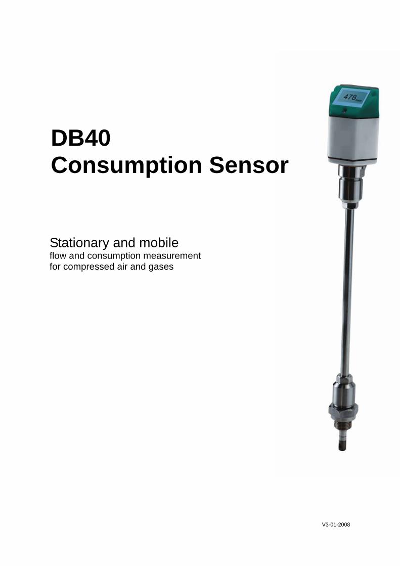
Stationary and mobile flow and consumption measurement for compressed air and gases
DB40 Consumption Sensor
2 V3-01-2008
CONTENT Page Introduction 2 Safety instructions 3-4 Technical data 5 Instruments description 6 Installation description 7-8 Pulse lengths 9 Measuring ranges DB40 - S 10-11 Measuring ranges DB40 - H1 12-13 Measuring ranges DB40 - H2 14-15 Drawing/Dimensions of the instrument 16 Connection of the instrument 16 Service information 17 Display functions 18-20 Calibration/adjustment 20 Warranty 21 Ordering data 21
INTRODUCTION Dear customer, Thousands of customers buy our high standard products every year. There are a few good reasons for doing so:
• The cost-performance ratio - reliable quality at a fair price. • We have the ideal solutions for your measuring tasks based on our expert
experience gained over 20 years. • Our high quality standard. • Of course, our instruments carry the CE symbol required by the EU. • We issue calibration certificates and hold seminars. • Also after the purchase we do not leave you out in the cold - we offer a good
after sales service. Our service guarantees fast help. Measuring instrument conforms with DIN EN 61326
3 V3-01-2008
SAFETY INSTRUCTIONS
Please read carefully before starting the device! The consumption sensor DB40 measures the flow velocity (calorimatric principle) in the middle of the pipe. Please observe mounting instruction and inlet section = 15 x inner diameter and outlet section = 5 x inner diameter. The final values of the measuring ranges are as follows: DB40 standard version 92.7 m/s, please take the flow rates from the tables on pages 10-11 DB40 H1 - version 185 m/s, please take the flow rates from the tables on pages 12-13 DB40 H2 - version 224 m/s, please take the flow rates from the tables on pages 14-15 1. DB40 with display with 4… 20 mA analogue and pulse output Please enter inner diameter of the pipe! Values indicated in the display: Actual value in m³/h, m³/min etc. Counter in m³ resp. l as well as pulse output, 1 pulse per m³ resp. l are calculated according to the set diameter. Please take the analogue value for flow rate 4… 20 mA from the tables on pages 10 to 15. 4 mA always corresponds with the starting value 0 m³/h, 0 m³/min. The final value 20 mA can be taken from the tables on pages 10 to 15. Example DB40 Standard: 1" with inner diameter 25.0 mm, 4 mA = 0 m³/h and 20 mA = 122.2 m³/h 2" with inner diameter 53.1 mm, 4 mA = 0 m³/h und 20 mA = 600.0 m³/h 2. DB40 without Display with 4… 20 mA analogue output (without pulse output) No adjustments are necessary at the consumption sensor. The respective final values for the flow rate can be taken from the tables on the pages 10 to 15. 4 mA is always set as scaling value 0. 20 mA is the final value . Example DB40 Standard: 1" with inner diameter 25.0 mm, 4 mA = 0 m³/h and 20 mA = 122.2 m³/h 2" with inner diameter 53.1 mm, 4 mA = 0 m³/h und 20 mA = 600.0 m³/h
!
4 V3-01-2008
Please read carefully before starting the device! Warning: Do not exceed the pressure range of 50 bar. From 10 bar we recommend to use the high-pressure protection for a safe installation and removal. Observe the measuring ranges of the sensor! Overheating destroys the sensor. Observe the admissible storage and transporation temperature as well as the permitted operating temperature (e. g. protect the instrument from direct insolation). Always observe the direction of flow when positioning the sensor! The safety ring at the sensor head must always remain undamaged and sit correctly in the destined slot. The screwed fixture must be pressure tight. The adapter sleeve must be tightened with a torque of 20 to 30 Nm. It is absolutely necessary to avoid condensation on the sensor element or water drops in the measuring air as they may cause faults . The lengths of the inlet and outlet sections must not fall below the specified minimum values as this causes increased deviations in the measuring results. The manufacturer cannot be held liable for any damage which occurs as a result of non-observance or non-compliance with these instructions. Should the device be tampered with in any matter other than a procedure which is described and specified in the manual, the warranty is cancelled and the manufacturer is exempt from liability. The device is destined exclusively for the described application. We offer no guarantee for the suitability for any other purpose and are not liable for errors which may have slipped into this operation manual. We are also not liable for consequential damage resulting from the delivery, capability or use of this device. We offer you to take back the instruments of the instruments family DB40 which you would like to dispose of. Adjustments and calibrations should only be carried out by qualified employees from the measurement and control technology branch.
SAFETY INSTRUCTIONS
!

5 V3-01-2008
TECHNICAL DATA
Measured variables: m³/h, m³/min, l/min or cfm, m/s (standard: DIN 1945, ISO 1217 at 20°C and 1000 mbar) mass flow on request (kg/s, kg/min, kg/h) Principle of measurement: calorimetric measurement Sensor: Pt45, Pt1000 Measuring medium: Air, gases Operating temperature: -30 ... 140°C probe tube -30 ... 80 °C housing Operating pressure: up to 50 bar Analogue output: 4 ... 20 mA (max. burden < 500 Ohm) Scaling: 0 to maximum flow rate (see tables on pages 10-15) Accuracy: 0.06 mA Pulse output: 1 pulse per m³ (see pulse diagram on page 8), max. voltage: pulse +P = +VB, active signal max. flow l = 10 mA Power supply: 12 to 30 VDC Power input: max. 80 mA at 24 VDC Accuracy: ± 3% m.v. with meas. section ± 2% m.v. (option via 5 point ISO precision calibration) These data are just valid in connection with a measuring section. Accuracy: ± 4% m.v. without meas. section ± 3% m.v. (option via 5 point ISO precision calibration) These data are just valid in case of correctly programmed inner diameter Display: 128 x 64 pixel, with backligth Measures values in maximum 6 digits, Counter max. up to 99,999,999 l resp. m³ drops then back to 0 Units: m³/h (standard factory settings) selectable via software m³/min, l/min, l/s, ft/min, cfm Screw-in thread: 1/2" Material: Probe tube and screwing: stainless steel 1,4301

6 V3-01-2008
INSTRUMENTS DESCRIPTION The DB40 is a consumption sensor with display for consumption measurement of compressed air and gases indicating the actual consumption in m³/h and the counter in m³. Special features: - Integrated display for m³/h and m³ - Depth scale for accurate installation - Usable from tube diameter 1/2" - Easy installation under pressure - 4...20 mA analogue output for m³/h resp. m³/min - Pulse output for m³ - Inner diameter adjustable via keyboard - Consumption counter resettable Programming via Service Software SFA 300. - Analogue output 4...20 mA scalable - Switching between m³/h, m³/min, ft/min, l/min, l/s, cfm, m/s - Reading out the service data
Determining the point of installation In order to maintain the accuracy stipulated in the data sheets, the sensor must be inserted in the centre of a straight pipe section with an undisturbed flow progression. An undisturbed flow progression is achieved if the sections in front of the sensor (inlet) and behind the sensor (outlet) are sufficiently long, absolutely straight and without any obstruc-tions such as edges, seams, curves etc. Careful attention must be paid to the design of the outlet section as obstructions can cause counter-flow turbulence as well as turbulence in the direction of the flow.
L = Length of the entire measuring section L1 = Length of inlet section L2 = Length of outlet section D = Diameter of measuring section
INSTALLATION DESCRIPTON
LL 1 L 2
D
flow
D/2 D/2
D/2
D/2
7 V3-01-2008
The following table shows the equalising sections necessary in relation to existing ob-structions:
INSTALLATION DESCRIPTION
Flow obstruction in front of the measuring section
Minimum length inlet (L1)
Minimum length outlet (L2)
Slight curve (bend < 90°) 12 x D 5 x D
Reduction (pipe narrows towards the meas. section) 15 x D 5 x D
Expansion (pipe expands towards the meas. section) 15 x D 5 x D
90° bend or T piece 15 x D 5 x D
2 bends á 90° on one level 20 x D 5 x D
2 bends á 90° 3-dimensional change of direction 35 x D 5 x D
Shut-off valve 45 x D 5 x D
Table of inlet and outlet sections
The respective minimum values required are indicated here. If it is not possible to observe the stipulated equalising sections, considerable deviations in measuring results must be expected. Sensor installation
Hint for the installation with ball valve: Ball valve R 1/2“, DN 15 Passage ball valve minimum Ø15 mm
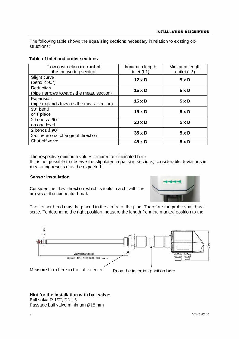
Consider the flow direction which should match with the arrows at the connector head.
Measure from here to the tube center Read the insertion position here
The sensor head must be placed in the centre of the pipe. Therefore the probe shaft has a scale. To determine the right position measure the length from the marked position to the
mm
8 V3-01-2008
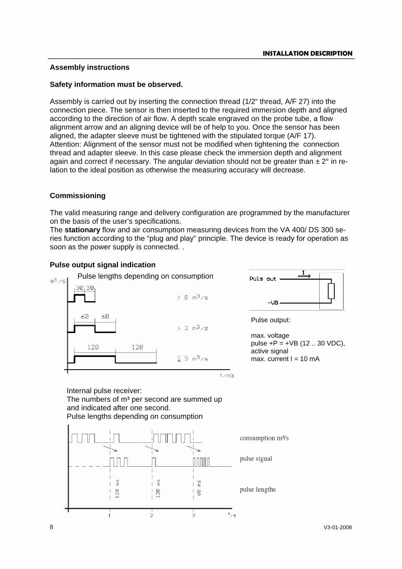
Pulse output signal indication
INSTALLATION DESCRIPTION
Assembly instructions Safety information must be observed. Assembly is carried out by inserting the connection thread (1/2“ thread, A/F 27) into the connection piece. The sensor is then inserted to the required immersion depth and aligned according to the direction of air flow. A depth scale engraved on the probe tube, a flow alignment arrow and an aligning device will be of help to you. Once the sensor has been aligned, the adapter sleeve must be tightened with the stipulated torque (A/F 17). Attention: Alignment of the sensor must not be modified when tightening the connection thread and adapter sleeve. In this case please check the immersion depth and alignment again and correct if necessary. The angular deviation should not be greater than ± 2° in re-lation to the ideal position as otherwise the measuring accuracy will decrease. Commissioning The valid measuring range and delivery configuration are programmed by the manufacturer on the basis of the user’s specifications. The stationary flow and air consumption measuring devices from the VA 400/ DS 300 se-ries function according to the “plug and play” principle. The device is ready for operation as soon as the power supply is connected. .
Pulse lengths depending on consumption
Internal pulse receiver: The numbers of m³ per second are summed up and indicated after one second. Pulse lengths depending on consumption
Pulse output: max. voltage pulse +P = +VB (12 .. 30 VDC), active signal max. current I = 10 mA
9 V3-01-2008
PULSE LENGTHS
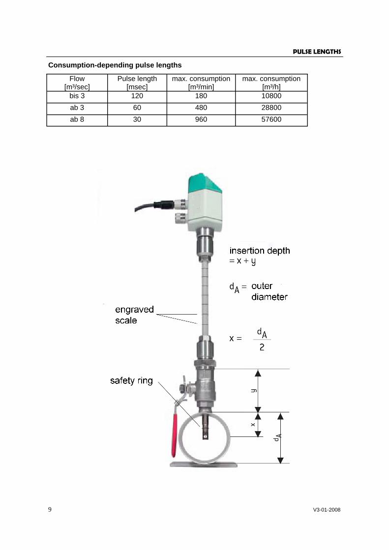
Consumption-depending pulse lengths
Flow [m³/sec]
Pulse length [msec]
max. consumption [m³/min]
max. consumption [m³/h]
bis 3 120 180 10800 ab 3 60 480 28800 ab 8 30 960 57600
10 V3-01-2008
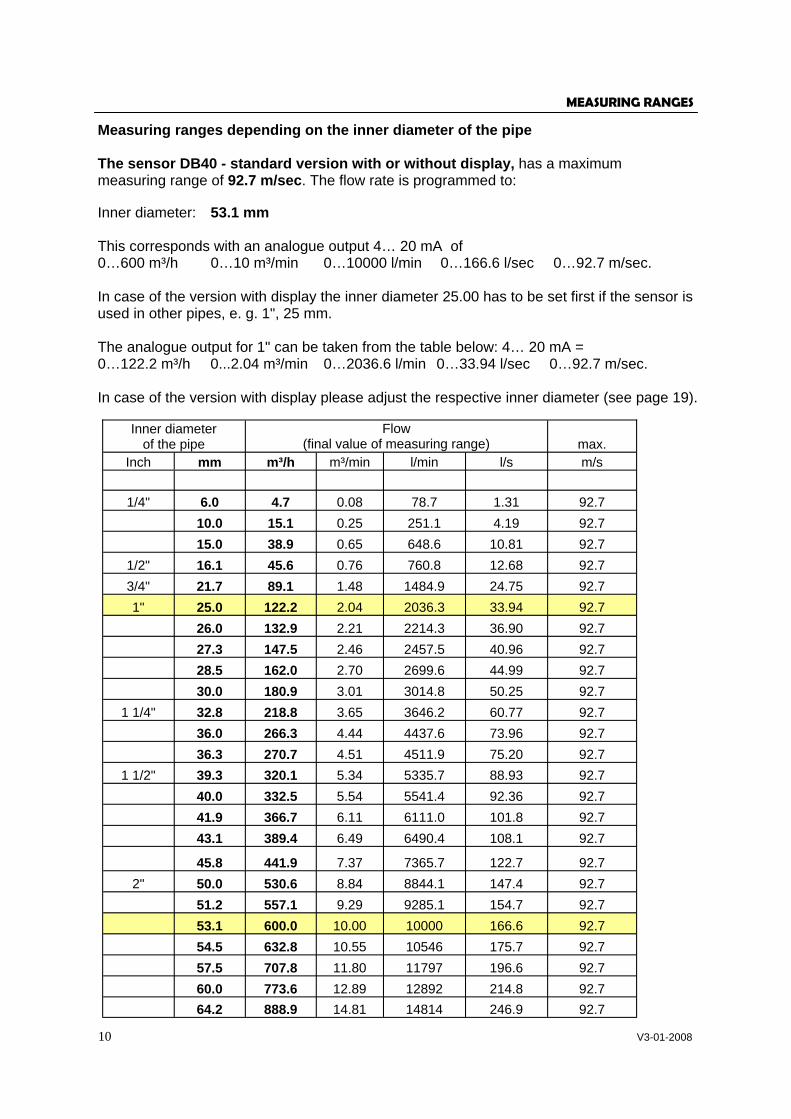
Measuring ranges depending on the inner diameter of the pipe The sensor DB40 - standard version with or without display, has a maximum measuring range of 92.7 m/sec. The flow rate is programmed to: Inner diameter: 53.1 mm This corresponds with an analogue output 4… 20 mA of 0…600 m³/h 0…10 m³/min 0…10000 l/min 0…166.6 l/sec 0…92.7 m/sec. In case of the version with display the inner diameter 25.00 has to be set first if the sensor is used in other pipes, e. g. 1", 25 mm. The analogue output for 1" can be taken from the table below: 4… 20 mA = 0…122.2 m³/h 0...2.04 m³/min 0…2036.6 l/min 0…33.94 l/sec 0…92.7 m/sec. In case of the version with display please adjust the respective inner diameter (see page 19).
Inner diameter of the pipe
Flow (final value of measuring range) max.
Inch mm m³/h m³/min l/min l/s m/s
1/4" 6.0 4.7 0.08 78.7 1.31 92.7 10.0 15.1 0.25 251.1 4.19 92.7 15.0 38.9 0.65 648.6 10.81 92.7
1/2" 16.1 45.6 0.76 760.8 12.68 92.7 3/4" 21.7 89.1 1.48 1484.9 24.75 92.7 1" 25.0 122.2 2.04 2036.3 33.94 92.7 26.0 132.9 2.21 2214.3 36.90 92.7 27.3 147.5 2.46 2457.5 40.96 92.7 28.5 162.0 2.70 2699.6 44.99 92.7 30.0 180.9 3.01 3014.8 50.25 92.7
1 1/4" 32.8 218.8 3.65 3646.2 60.77 92.7 36.0 266.3 4.44 4437.6 73.96 92.7 36.3 270.7 4.51 4511.9 75.20 92.7
1 1/2" 39.3 320.1 5.34 5335.7 88.93 92.7 40.0 332.5 5.54 5541.4 92.36 92.7 41.9 366.7 6.11 6111.0 101.8 92.7 43.1 389.4 6.49 6490.4 108.1 92.7
45.8 441.9 7.37 7365.7 122.7 92.7 2" 50.0 530.6 8.84 8844.1 147.4 92.7 51.2 557.1 9.29 9285.1 154.7 92.7 53.1 600.0 10.00 10000 166.6 92.7 54.5 632.8 10.55 10546 175.7 92.7 57.5 707.8 11.80 11797 196.6 92.7 60.0 773.6 12.89 12892 214.8 92.7 64.2 888.9 14.81 14814 246.9 92.7
MEASURING RANGES

11 V3-01-2008
Measuring ranges depending from the inner diameter of the pipe
MEASURING RANGES
Sonde DB40 - standard version up to 92.7 m/sec.
Inner diameter of the pipe
Flow (final value of measuring range) max.
Inch mm m³/h m³/min l/min l/s m/s
2 1/2" 65.0 913.5 15.22 15224 253.7 92.7 70.3 1071.1 17.85 17851 297.5 92.7 71.1 1095.6 18.26 18260 304.3 92.7 76.1 1258.2 20.97 20969 349.4 92.7
3" 80.0 1390.4 23.17 23173 386.2 92.7 81.0 1425.4 23.76 23756 395.9 92.7 82.5 1480.5 24.67 24674 411.2 92.7 84.9 1569.8 26.16 26162 436.0 92.7 90.0 1766.1 29.44 29435 490.6 92.7
4" 100.0 2183.1 36.38 36384 606.4 92.7 107.1 2507.1 41.78 41784 696.4 92.7 110.0 2644.7 44.08 44077 734.6 92.7
5" 125.0 3423.3 57.1 57055 950.9 92.7 133.7 3921.1 65.4 65351 1089.2 92.7
6" 150.0 4941.4 82.4 82356 1372.6 92.7 159.3 5579.8 93.0 92996 1549.9 92.7 182.5 7323.4 122.1 122055 2034.3 92.7 190.0 7947.1 132.5 132451 2207.5 92.7
8" 200.0 8816.2 146.9 146936 2448.9 92.7 206.5 9398.5 156.6 156642 2610.7 92.7
10" 250.0 13775 229.6 229587 3826.5 92.7 260.4 14945 249.1 249086 4151.4 92.7
12" 300.0 19836 330.6 330606 5510.1 92.7 309.7 21139 352.3 352331 5872.2 92.7 339.6 25418 423.6 423646 7060.8 92.7 388.8 33317 555.3 555291 9254.9 92.7 500.0 55101 918.4 918350 15305 92.7 600.0 79345 1322 1322424 22040 92.7 700.0 107998 1800 1799966 29999 92.7 800.0 141058 2351 2350976 39182 92.7 900.0 178527 2975 2975455 49590 92.7 1000.0 220404 3673 3673401 61223 92.7
12 V3-01-2008
Measuring ranges depending from the inner diameter of the pipe
MEASURING RANGES
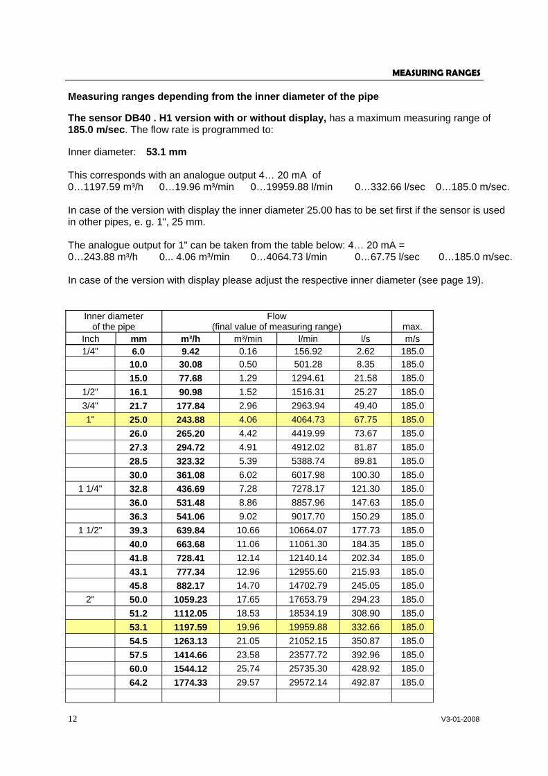
The sensor DB40 . H1 version with or without display, has a maximum measuring range of 185.0 m/sec. The flow rate is programmed to: Inner diameter: 53.1 mm This corresponds with an analogue output 4… 20 mA of 0…1197.59 m³/h 0…19.96 m³/min 0…19959.88 l/min 0…332.66 l/sec 0…185.0 m/sec. In case of the version with display the inner diameter 25.00 has to be set first if the sensor is used in other pipes, e. g. 1", 25 mm. The analogue output for 1" can be taken from the table below: 4… 20 mA = 0…243.88 m³/h 0... 4.06 m³/min 0…4064.73 l/min 0…67.75 l/sec 0…185.0 m/sec. In case of the version with display please adjust the respective inner diameter (see page 19).
Inner diameter of the pipe
Flow (final value of measuring range) max.
Inch mm m³/h m³/min l/min l/s m/s
1/4" 6.0 9.42 0.16 156.92 2.62 185.0 10.0 30.08 0.50 501.28 8.35 185.0 15.0 77.68 1.29 1294.61 21.58 185.0
1/2" 16.1 90.98 1.52 1516.31 25.27 185.0 3/4" 21.7 177.84 2.96 2963.94 49.40 185.0 1" 25.0 243.88 4.06 4064.73 67.75 185.0 26.0 265.20 4.42 4419.99 73.67 185.0 27.3 294.72 4.91 4912.02 81.87 185.0 28.5 323.32 5.39 5388.74 89.81 185.0 30.0 361.08 6.02 6017.98 100.30 185.0
1 1/4" 32.8 436.69 7.28 7278.17 121.30 185.0 36.0 531.48 8.86 8857.96 147.63 185.0 36.3 541.06 9.02 9017.70 150.29 185.0
1 1/2" 39.3 639.84 10.66 10664.07 177.73 185.0 40.0 663.68 11.06 11061.30 184.35 185.0 41.8 728.41 12.14 12140.14 202.34 185.0 43.1 777.34 12.96 12955.60 215.93 185.0 45.8 882.17 14.70 14702.79 245.05 185.0
2" 50.0 1059.23 17.65 17653.79 294.23 185.0 51.2 1112.05 18.53 18534.19 308.90 185.0 53.1 1197.59 19.96 19959.88 332.66 185.0 54.5 1263.13 21.05 21052.15 350.87 185.0 57.5 1414.66 23.58 23577.72 392.96 185.0 60.0 1544.12 25.74 25735.30 428.92 185.0 64.2 1774.33 29.57 29572.14 492.87 185.0
13 V3-01-2008
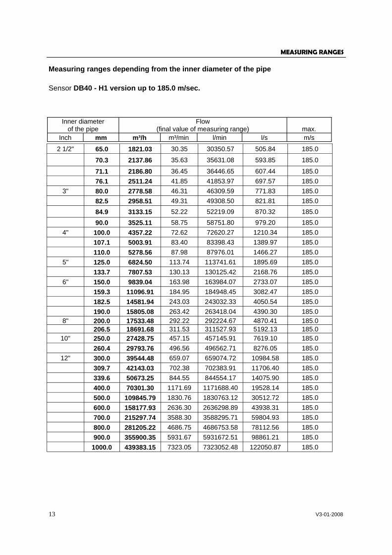
Measuring ranges depending from the inner diameter of the pipe
MEASURING RANGES
Sensor DB40 - H1 version up to 185.0 m/sec.
Inner diameter of the pipe
Flow (final value of measuring range) max.
Inch mm m³/h m³/min l/min l/s m/s
2 1/2" 65.0 1821.03 30.35 30350.57 505.84 185.0
70.3 2137.86 35.63 35631.08 593.85 185.0
71.1 2186.80 36.45 36446.65 607.44 185.0 76.1 2511.24 41.85 41853.97 697.57 185.0
3" 80.0 2778.58 46.31 46309.59 771.83 185.0 82.5 2958.51 49.31 49308.50 821.81 185.0 84.9 3133.15 52.22 52219.09 870.32 185.0 90.0 3525.11 58.75 58751.80 979.20 185.0
4" 100.0 4357.22 72.62 72620.27 1210.34 185.0 107.1 5003.91 83.40 83398.43 1389.97 185.0 110.0 5278.56 87.98 87976.01 1466.27 185.0
5" 125.0 6824.50 113.74 113741.61 1895.69 185.0 133.7 7807.53 130.13 130125.42 2168.76 185.0
6" 150.0 9839.04 163.98 163984.07 2733.07 185.0 159.3 11096.91 184.95 184948.45 3082.47 185.0 182.5 14581.94 243.03 243032.33 4050.54 185.0 190.0 15805.08 263.42 263418.04 4390.30 185.0
8" 200.0 17533.48 292.22 292224.67 4870.41 185.0 206.5 18691.68 311.53 311527.93 5192.13 185.0
10" 250.0 27428.75 457.15 457145.91 7619.10 185.0 260.4 29793.76 496.56 496562.71 8276.05 185.0
12" 300.0 39544.48 659.07 659074.72 10984.58 185.0 309.7 42143.03 702.38 702383.91 11706.40 185.0 339.6 50673.25 844.55 844554.17 14075.90 185.0 400.0 70301.30 1171.69 1171688.40 19528.14 185.0 500.0 109845.79 1830.76 1830763.12 30512.72 185.0 600.0 158177.93 2636.30 2636298.89 43938.31 185.0 700.0 215297.74 3588.30 3588295.71 59804.93 185.0 800.0 281205.22 4686.75 4686753.58 78112.56 185.0 900.0 355900.35 5931.67 5931672.51 98861.21 185.0 1000.0 439383.15 7323.05 7323052.48 122050.87 185.0
14 V3-01-2008
Measuring ranges depending from the inner diameter of the pipe
MEASURING RANGES
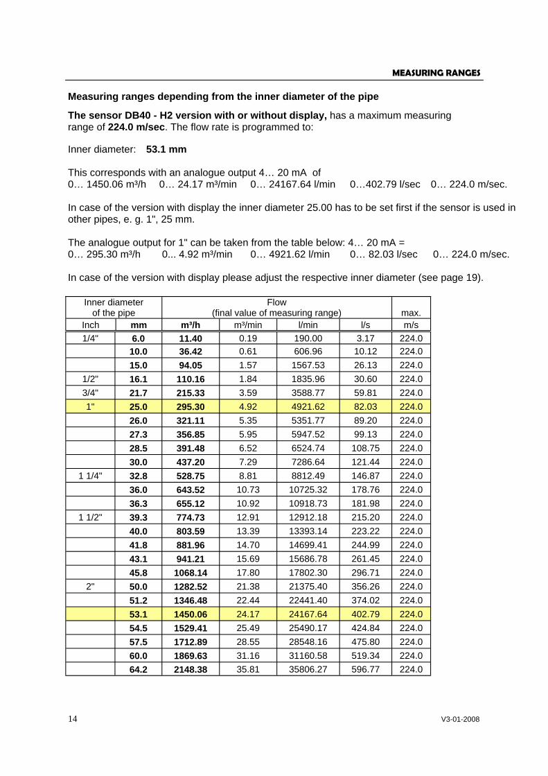
The sensor DB40 - H2 version with or without display, has a maximum measuring range of 224.0 m/sec. The flow rate is programmed to: Inner diameter: 53.1 mm This corresponds with an analogue output 4… 20 mA of 0… 1450.06 m³/h 0… 24.17 m³/min 0… 24167.64 l/min 0…402.79 l/sec 0… 224.0 m/sec. In case of the version with display the inner diameter 25.00 has to be set first if the sensor is used in other pipes, e. g. 1", 25 mm. The analogue output for 1" can be taken from the table below: 4… 20 mA = 0… 295.30 m³/h 0... 4.92 m³/min 0… 4921.62 l/min 0… 82.03 l/sec 0… 224.0 m/sec. In case of the version with display please adjust the respective inner diameter (see page 19).
Inner diameter of the pipe
Flow (final value of measuring range) max.
Inch mm m³/h m³/min l/min l/s m/s
1/4" 6.0 11.40 0.19 190.00 3.17 224.0 10.0 36.42 0.61 606.96 10.12 224.0 15.0 94.05 1.57 1567.53 26.13 224.0
1/2" 16.1 110.16 1.84 1835.96 30.60 224.0 3/4" 21.7 215.33 3.59 3588.77 59.81 224.0 1" 25.0 295.30 4.92 4921.62 82.03 224.0 26.0 321.11 5.35 5351.77 89.20 224.0 27.3 356.85 5.95 5947.52 99.13 224.0 28.5 391.48 6.52 6524.74 108.75 224.0 30.0 437.20 7.29 7286.64 121.44 224.0
1 1/4" 32.8 528.75 8.81 8812.49 146.87 224.0 36.0 643.52 10.73 10725.32 178.76 224.0 36.3 655.12 10.92 10918.73 181.98 224.0
1 1/2" 39.3 774.73 12.91 12912.18 215.20 224.0 40.0 803.59 13.39 13393.14 223.22 224.0 41.8 881.96 14.70 14699.41 244.99 224.0 43.1 941.21 15.69 15686.78 261.45 224.0 45.8 1068.14 17.80 17802.30 296.71 224.0
2" 50.0 1282.52 21.38 21375.40 356.26 224.0 51.2 1346.48 22.44 22441.40 374.02 224.0 53.1 1450.06 24.17 24167.64 402.79 224.0 54.5 1529.41 25.49 25490.17 424.84 224.0 57.5 1712.89 28.55 28548.16 475.80 224.0 60.0 1869.63 31.16 31160.58 519.34 224.0 64.2 2148.38 35.81 35806.27 596.77 224.0
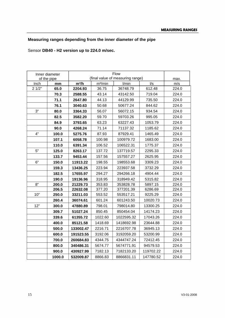
15 V3-01-2008
Measuring ranges depending from the inner diameter of the pipe
MEASURING RANGES
Sensor DB40 - H2 version up to 224.0 m/sec.
Inner diameter of the pipe
Flow (final value of measuring range) max.
Inch mm m³/h m³/min l/min l/s m/s
2 1/2" 65.0 2204.93 36.75 36748.79 612.48 224.0 70.3 2588.55 43.14 43142.50 719.04 224.0 71.1 2647.80 44.13 44129.99 735.50 224.0 76.1 3040.63 50.68 50677.24 844.62 224.0
3" 80.0 3364.33 56.07 56072.15 934.54 224.0 82.5 3582.20 59.70 59703.26 995.05 224.0 84.9 3793.65 63.23 63227.43 1053.79 224.0 90.0 4268.24 71.14 71137.32 1185.62 224.0
4" 100.0 5275.76 87.93 87929.41 1465.49 224.0 107.1 6058.78 100.98 100979.72 1683.00 224.0 110.0 6391.34 106.52 106522.31 1775.37 224.0
5" 125.0 8263.17 137.72 137719.57 2295.33 224.0 133.7 9453.44 157.56 157557.27 2625.95 224.0
6" 150.0 11913.22 198.55 198553.68 3309.23 224.0 159.3 13436.25 223.94 223937.58 3732.29 224.0 182.5 17655.97 294.27 294266.18 4904.44 224.0 190.0 19136.96 318.95 318949.42 5315.82 224.0
8" 200.0 21229.73 353.83 353828.78 5897.15 224.0 206.5 22632.08 377.20 377201.39 6286.69 224.0
10" 250.0 33211.03 553.52 553517.21 9225.29 224.0 260.4 36074.61 601.24 601243.50 10020.73 224.0
12" 300.0 47880.89 798.01 798014.80 13300.25 224.0 309.7 51027.24 850.45 850454.04 14174.23 224.0 339.6 61355.72 1022.60 1022595.32 17043.26 224.0 400.0 85121.58 1418.69 1418692.98 23644.88 224.0 500.0 133002.47 2216.71 2216707.78 36945.13 224.0 600.0 191523.55 3192.06 3192059.20 53200.99 224.0 700.0 260684.83 4344.75 4344747.24 72412.45 224.0 800.0 340486.31 5674.77 5674771.91 94579.53 224.0 900.0 430927.99 7182.13 7182133.20 119702.22 224.0 1000.0 532009.87 8866.83 8866831.11 147780.52 224.0
16 V3-01-2008
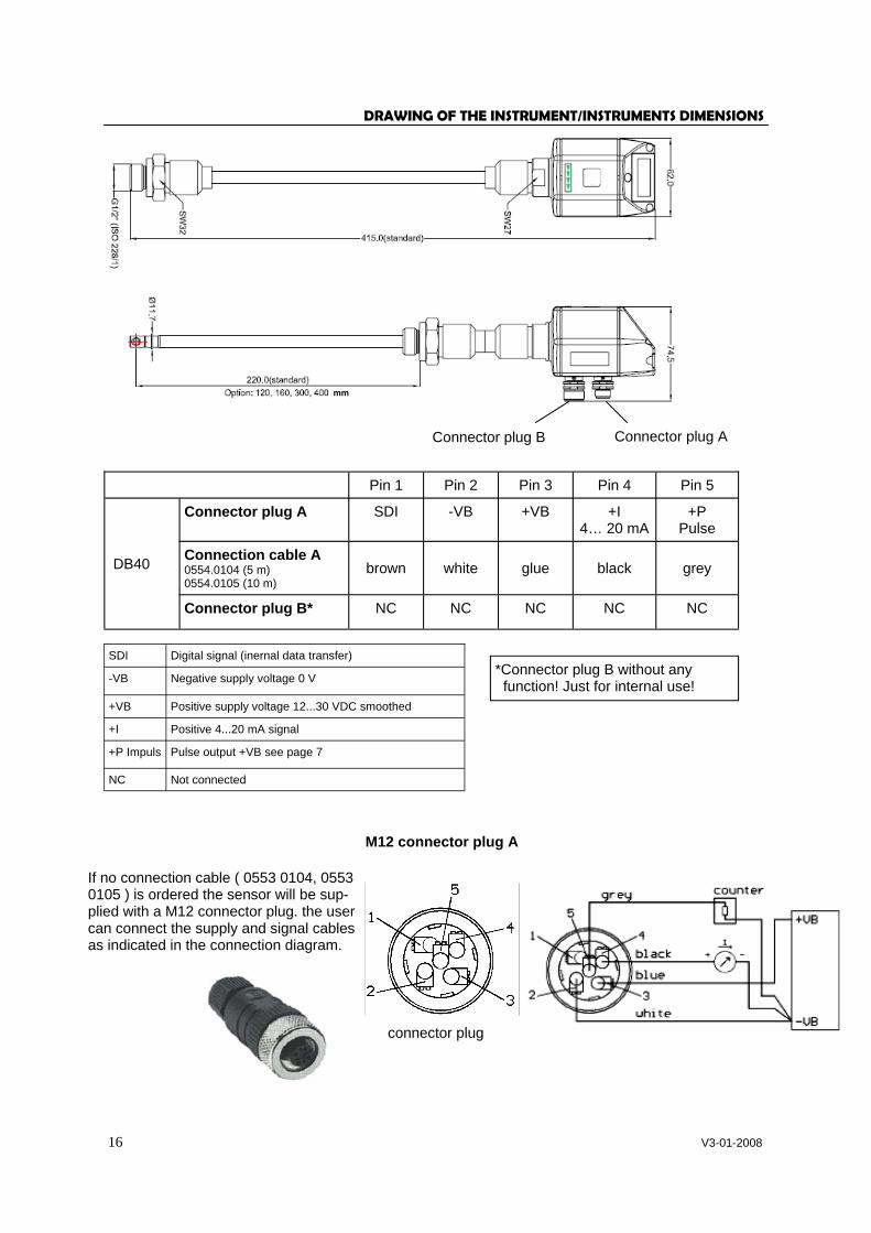
Connector plug A Connector plug B
DRAWING OF THE INSTRUMENT/INSTRUMENTS DIMENSIONS
mm
Pin 1 Pin 2 Pin 3 Pin 4 Pin 5
DB40
Connector plug A SDI -VB +VB +I 4… 20 mA
+P Pulse
Connection cable A 0554.0104 (5 m) 0554.0105 (10 m)
brown white glue black grey
Connector plug B* NC NC NC NC NC
SDI Digital signal (inernal data transfer)
-VB Negative supply voltage 0 V
+VB Positive supply voltage 12...30 VDC smoothed
+I Positive 4...20 mA signal
+P Impuls Pulse output +VB see page 7
NC Not connected
If no connection cable ( 0553 0104, 0553 0105 ) is ordered the sensor will be sup-plied with a M12 connector plug. the user can connect the supply and signal cables as indicated in the connection diagram.
M12 connector plug A
connector plug
*Connector plug B without any function! Just for internal use!

17 V3-01-2008
SERVICE INFORMATION
Maintenance The sensor head should be checked regularly for dirt and cleaned if necessary. Should dirt, dust or oil accumulate on the sensor element, a deviation will occur in the measuring value. An annual check is recommended. Should the compressed air be heavily soiled this interval must be shortened. Cleaning of the sensor head The sensor head can be cleaned by carefully moving it to and fro in warm water with a small amount of washing-up liquid. Avoid physical intervention on the sensor (e. g. using a sponge or brush). If soiling cannot be removed, service and maintenance must be carried out by the manufacturer. Re-calibration If no customer specifications are given then we recommend to carry out calibration every 12 months. For this purpose the sensor must be sent to the manufacturer. Spare parts and repair For reasons of measuring accuracy spare parts are not available. If parts are faulty they must be sent to the supplier for repair. If the measuring device is used in important company installations we recommend to keep a spare measuring system ready. Calibration certificates Calibration certificates are issued by the manufacturer on request. This is a fee-paying service. Precision is tested with PTB (German National Metrology Institute) volume flow nozzles.
18 V3-01-2008
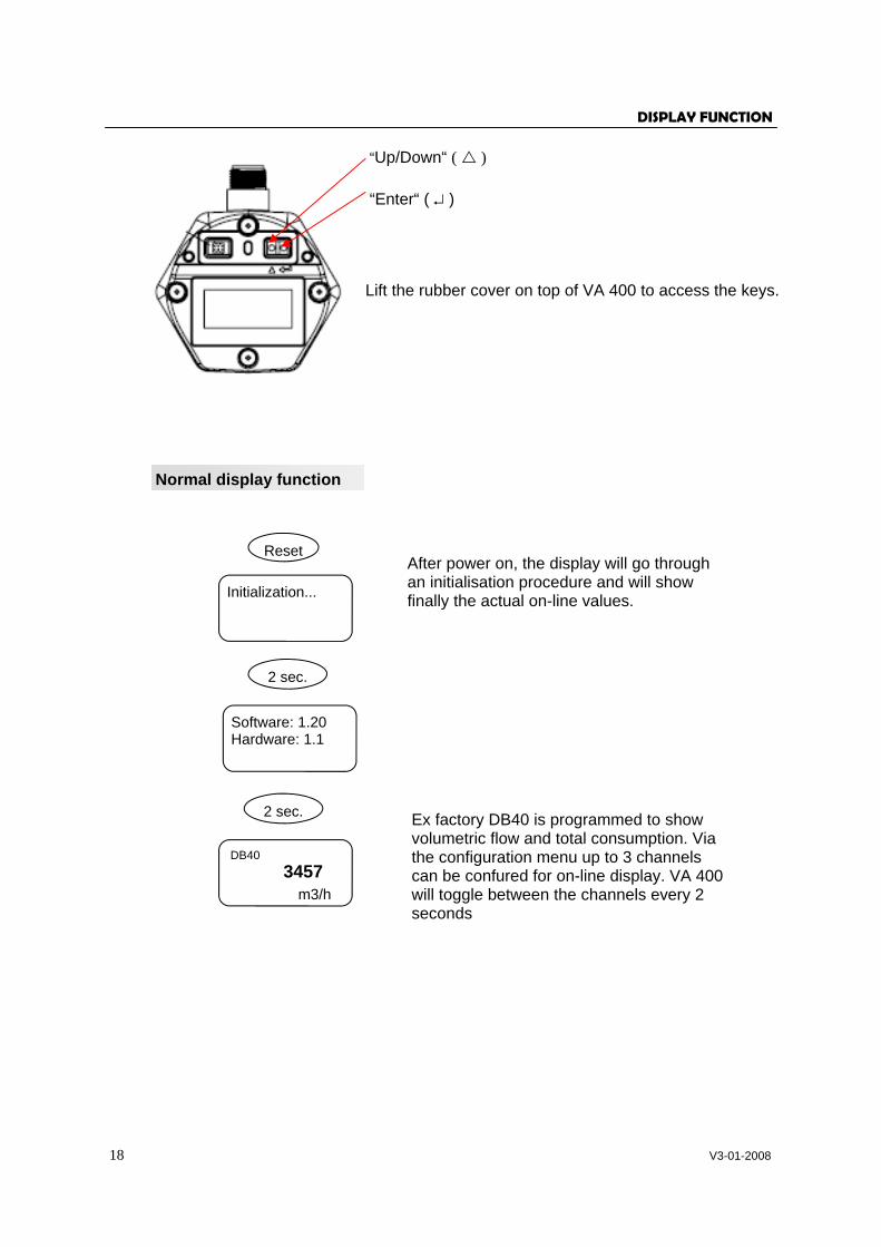
DISPLAY FUNCTION
Lift the rubber cover on top of VA 400 to access the keys.
“Enter“ ( ↵ )
“Up/Down“ ( )
Normal display function
Initialization...
Reset
2 sec.
Software: 1.20 Hardware: 1.1
2 sec.
DB40
3457 m3/h
After power on, the display will go through an initialisation procedure and will show finally the actual on-line values.
Ex factory DB40 is programmed to show volumetric flow and total consumption. Via the configuration menu up to 3 channels can be confured for on-line display. VA 400 will toggle between the channels every 2 seconds
19 V3-01-2008
DISPLAY FUNCTION
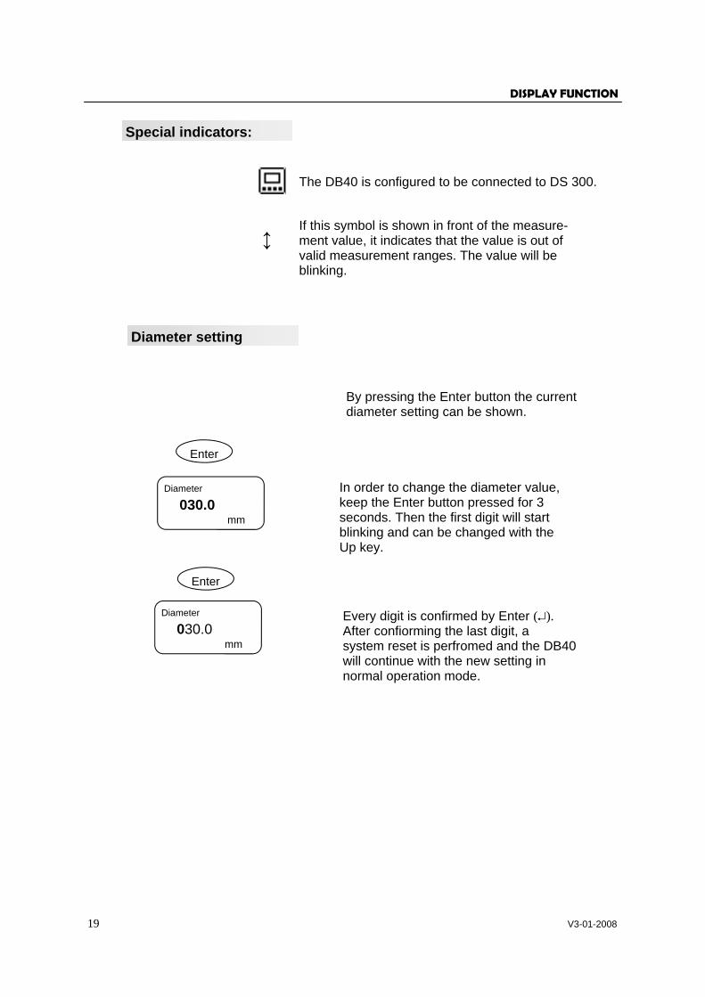
The DB40 is configured to be connected to DS 300.
↕ If this symbol is shown in front of the measure-ment value, it indicates that the value is out of valid measurement ranges. The value will be blinking.
Enter
Diameter
030.0 mm
Enter
Diameter
030.0 mm
Diameter setting
By pressing the Enter button the current diameter setting can be shown.
In order to change the diameter value, keep the Enter button pressed for 3 seconds. Then the first digit will start blinking and can be changed with the Up key.
Every digit is confirmed by Enter (↵). After confiorming the last digit, a system reset is perfromed and the DB40 will continue with the new setting in normal operation mode.
Special indicators:

20 V3-01-2008
DISPLAY FUNCTION
CALIBRATION/ADJUSTMENT
According to DIN ISO certification of the measuring instruments we recommend to calibrate and if applicable to adjust the instruments regularly from the manufacturer. The calibration intervals should comply with your internal specificaton. According to DIN ISO we recommend a calibration interval of one year for the instrument DB40.
Configuration setting
The DB40 is usually configured ex factory according to the customer settings ordered. In case settings have to be changed, the user has to keep the Enter key (↵) pressed while powering up the device.
IS DS 300 connected?
Yes / No
Display 1
Volume flow
Consumption
3457
Up change Enter OK
Contrast setting
Save changes No Yes
Enter “Yes” if there is a DS 300 con-nected to the DB40, otherwise No. Con-firm setting with Enter key (↵).
The DB40 can display up to 3 channels, which are volumetric flow or mass flow, velocity and total con-sumption. Use the Up-key to select the desired channel. If no further channel is wanted, please se-lect “nothing”. The channels are toggled during nor-mal operation mode very 2 seconds.
In this step the total consumption counter can be reset to zero.
Display contrast can be adjusted.
Press Enter-key to confirm the setting changes or press Up-key to discard all changes.
21 V3-01-2008
ORDERING DATA
see data sheet in appendix
WARRANTY
If you have reason for complaint we will of course repair any faults free of charge if it can be proven that they are manufacturing faults. The fault should be reported immediately after it has been found and within the warranty time guaranteed by us. Excluded from this warranty is damage caused by improper use and non adherence to the instruction manual. The warranty is also cancelled once the instrument has been opened - as far as this has not been mentioned in the instruction manual for maintenance purposes - or if the serial number in the instrument has been changed, damaged or removed. The warranty time for the DB40 is 12 months. If no other definitions are given the accessory parts have a warranty time of 6 months. Warranty services do not extend the warranty time. If in addition to the warranty service necessary repairs, adjustments or similar are carried out the warranty services are free of charge but there is a charge for other services such as transport and packaging costs. Other claims, especially those for damage occurring outside the instrument, are not included unless responsibility is legally binding. After sales service after the warranty time has elapsed We are of course there for you even after the warranty time has elapsed. In case of malfunctions please send us the instrument with a short-form description of the fault. Please do not forget to indicate your telephone number so that we can call you in case of any questions.
6/09
Flow Metering and Monitoring Systems
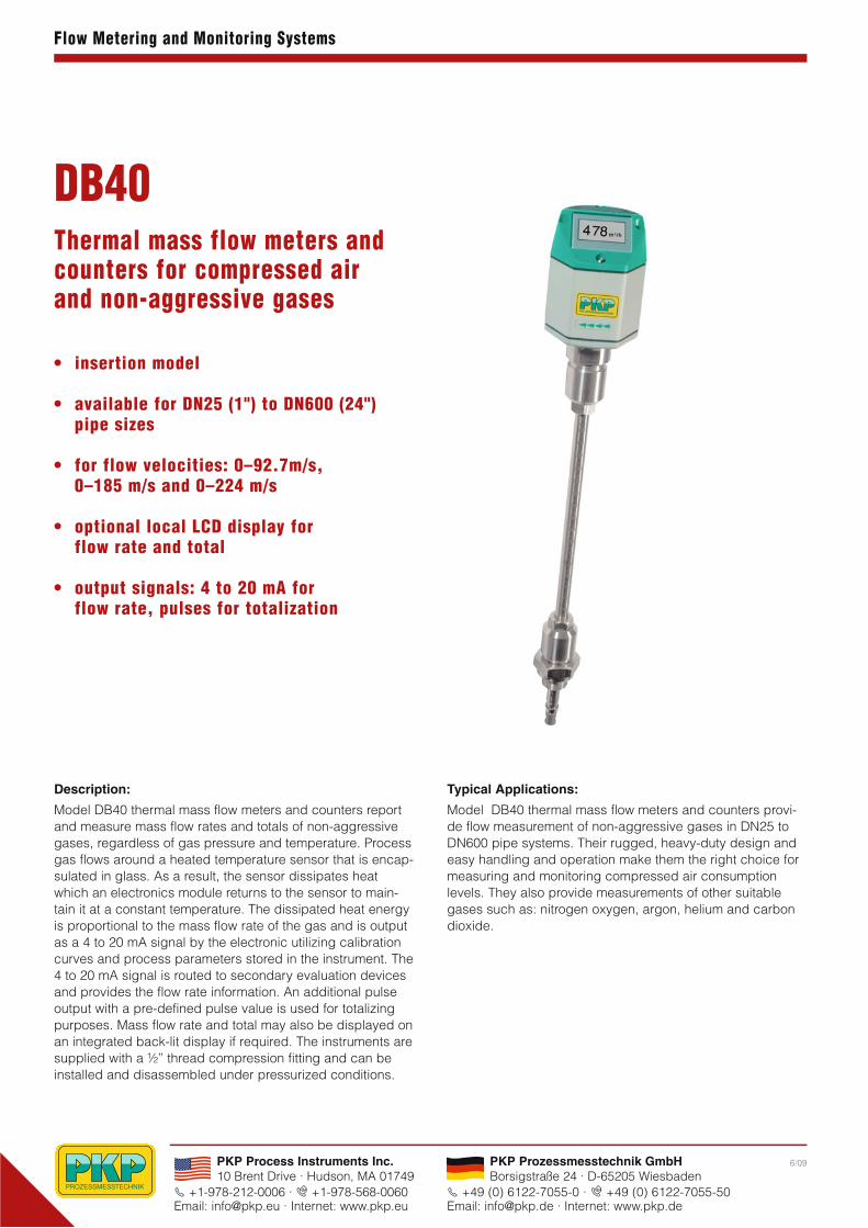
Thermal mass flow meters andcounters for compressed airand non-aggressive gases
• insertion model
• available for DN25 (1") to DN600 (24")pipe sizes
• for flow velocities: 0–92.7m/s, 0–185 m/s and 0–224 m/s
• optional local LCD display for flow rate and total
• output signals: 4 to 20 mA for flow rate, pulses for totalization
DB40
Description:
Model DB40 thermal mass flow meters and counters reportand measure mass flow rates and totals of non-aggressivegases, regardless of gas pressure and temperature. Processgas flows around a heated temperature sensor that is encap-sulated in glass. As a result, the sensor dissipates heatwhich an electronics module returns to the sensor to main-tain it at a constant temperature. The dissipated heat energyis proportional to the mass flow rate of the gas and is outputas a 4 to 20 mA signal by the electronic utilizing calibrationcurves and process parameters stored in the instrument. The4 to 20 mA signal is routed to secondary evaluation devicesand provides the flow rate information. An additional pulseoutput with a pre-defined pulse value is used for totalizingpurposes. Mass flow rate and total may also be displayed onan integrated back-lit display if required. The instruments aresupplied with a ½” thread compression fitting and can be installed and disassembled under pressurized conditions.
Typical Applications:
Model DB40 thermal mass flow meters and counters provi-de flow measurement of non-aggressive gases in DN25 toDN600 pipe systems. Their rugged, heavy-duty design andeasy handling and operation make them the right choice formeasuring and monitoring compressed air consumption levels. They also provide measurements of other suitable gases such as: nitrogen oxygen, argon, helium and carbondioxide.
PKP Process Instruments Inc.10 Brent Drive · Hudson, MA 01749
S +1-978-212-0006 · T +1-978-568-0060Email: [email protected] · Internet: www.pkp.eu
PKP Prozessmesstechnik GmbHBorsigstraße 24 · D-65205 Wiesbaden
S +49 (0) 6122-7055-0 · T +49 (0) 6122-7055-50Email: [email protected] · Internet: www.pkp.de
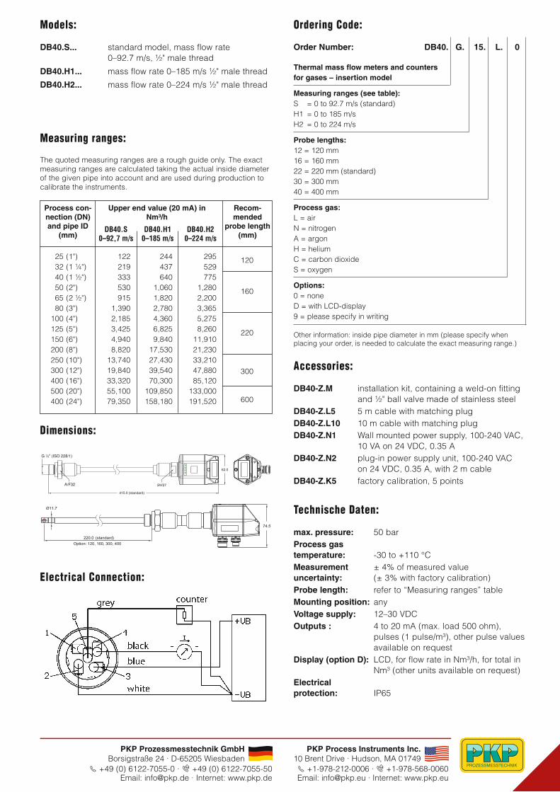
Models:
DB40.S... standard model, mass flow rate 0–92.7 m/s, ½" male thread
DB40.H1... mass flow rate 0–185 m/s ½" male thread
DB40.H2... mass flow rate 0–224 m/s ½" male thread
The quoted measuring ranges are a rough guide only. The exactmeasuring ranges are calculated taking the actual inside diameterof the given pipe into account and are used during production tocalibrate the instruments.
Dimensions:
Electrical Connection:
25 (1")32 (1 ¼")40 (1 ½")50 (2")65 (2 ½")80 (3")
100 (4")125 (5")150 (6")200 (8")250 (10")300 (12")400 (16")500 (20")400 (24")
120
160
220
300
600
122219333530915
1,3902,1853,4254,9408,820
13,74019,84033,32055,10079,350
244437640
1,0601,8202,7804,3606,8259,840
17,53027,43039,54070,300
109,850158,180
295529775
1,2802,2003,3655,2758,260
11,91021,23033,21047,88085,120
133,000191,520
Process con-nection (DN)and pipe ID
(mm)
Upper end value (20 mA) inNm³/h
DB40.S0–92,7 m/s
DB40.H20–224 m/s
DB40.H10–185 m/s
Recom -mended
probe length(mm)
Ordering Code:
Order Number: DB40. G. 15. L. 0
Thermal mass flow meters and counters for gases – insertion model
Measuring ranges (see table):S = 0 to 92.7 m/s (standard)H1 = 0 to 185 m/sH2 = 0 to 224 m/s
Probe lengths:12 = 120 mm16 = 160 mm22 = 220 mm (standard)30 = 300 mm40 = 400 mm
Process gas:L = airN = nitrogenA = argonH = heliumC = carbon dioxideS = oxygen
Options:0 = noneD = with LCD-display9 = please specify in writing
Technische Daten:
max. pressure: 50 barProcess gas temperature: -30 to +110 °CMeasurement ± 4% of measured valueuncertainty: (± 3% with factory calibration)Probe length: refer to “Measuring ranges” tableMounting position: anyVoltage supply: 12–30 VDCOutputs : 4 to 20 mA (max. load 500 ohm),
pulses (1 pulse/m³), other pulse valuesavailable on request
Display (option D): LCD, for flow rate in Nm³/h, for total inNm³ (other units available on request)
Electrical protection: IP65
Accessories:
DB40-Z.M installation kit, containing a weld-on fittingand ½" ball valve made of stainless steel
DB40-Z.L5 5 m cable with matching plugDB40-Z.L10 10 m cable with matching plugDB40-Z.N1 Wall mounted power supply, 100-240 VAC,
10 VA on 24 VDC, 0.35 ADB40-Z.N2 plug-in power supply unit, 100-240 VAC
on 24 VDC, 0.35 A, with 2 m cableDB40-Z.K5 factory calibration, 5 points
Other information: inside pipe diameter in mm (please specify when placing your order, is needed to calculate the exact measuring range.)
PKP Process Instruments Inc.10 Brent Drive · Hudson, MA 01749S +1-978-212-0006 · T +1-978-568-0060Email: [email protected] · Internet: www.pkp.eu
PKP Prozessmesstechnik GmbHBorsigstraße 24 · D-65205 Wiesbaden
S +49 (0) 6122-7055-0 · T +49 (0) 6122-7055-50Email: [email protected] · Internet: www.pkp.de
Measuring ranges: