operating instructions betriebsanleitung magnetic float ... · pdf filede en operating...
TRANSCRIPT
DE
EN
Operating instructionsBetriebsanleitung
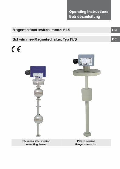
Magnetic float switch, model FLS
Schwimmer-Magnetschalter, Typ FLS
Stainless steel versionmounting thread
Plastic versionflange connection
2
0018
88.0
4 05
/201
7 EN
/DE
Operating instructions, magnetic float switch, model FLS
DE
EN Operating instructions model FLS Page 3 - 22
Betriebsanleitung Typ FLS Seite 23 - 42
© 06/2016 WIKA Alexander Wiegand SE & Co. KGAll rights reserved. / Alle Rechte vorbehalten.WIKA® and KSR® are registered trademarks in various countries.WIKA® and KSR® sind geschützte Marken in verschiedenen Ländern.
Prior to starting any work, read the operating instructions!Keep for later use!
Vor Beginn aller Arbeiten Betriebsanleitung lesen!Zum späteren Gebrauch aufbewahren!
EN
Operating instructions, magnetic float switch, model FLS
0018
88.0
4 05
/201
7 EN
/DE
3
Contents
Contents
Declarations of conformity can be found online at www.wika.com.
1. General information 42. Design and function 53. Safety 64. Transport, packaging and storage 115. Commissioning, operation 116. Faults 187. Maintenance and cleaning 198. Dismounting, return and disposal 219. Specifications 22
EN
0018
88.0
4 05
/201
7 EN
/DE
4 Operating instructions, magnetic float switch, model FLS
1. General information
■ The magnetic float switches described in the operating instructions have been designed and manufactured using state-of-the-art technology. All components are subject to stringent quality and environmental criteria during production. Our management systems are certified to ISO 9001.
■ These operating instructions contain important information on handling the instrument. Working safely requires that all safety instructions and work instructions are observed.
■ Observe the relevant local accident prevention regulations and general safety regulations for the instrument’s range of use.
■ The operating instructions are part of the product and must be kept in the immediate vicinity of the instrument and readily accessible to skilled personnel at any time. Pass the operating instructions on to the next operator or owner of the instrument.
■ Skilled personnel must have carefully read and understood the operating instructions prior to beginning any work.
■ The general terms and conditions contained in the sales documentation shall apply.
■ Subject to technical modifications.
■ Further information:- Internet address: www.wika.de / www.wika.com- Relevant data sheet: LM 30.01
Abbreviations, definitionsL-SP Level switch pointT-SP Temperature switch pointNO/NC Normally open/normally closedCO Change-over
1. General information
≤ 30°
EN
Operating instructions, magnetic float switch, model FLS
0018
88.0
4 05
/201
7 EN
/DE
5
2. Design and function
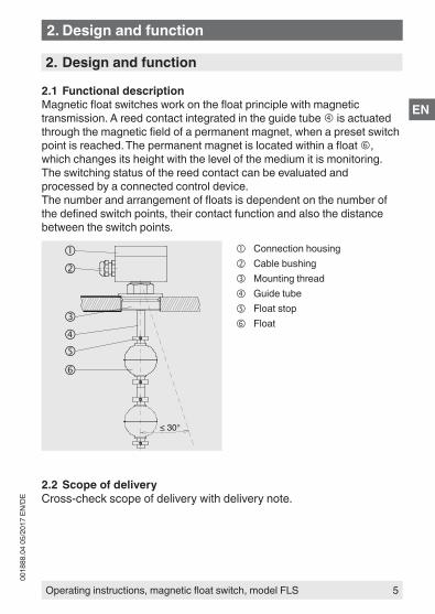
2.1 Functional descriptionMagnetic float switches work on the float principle with magnetic transmission. A reed contact integrated in the guide tube is actuated through the magnetic field of a permanent magnet, when a preset switch point is reached. The permanent magnet is located within a float , which changes its height with the level of the medium it is monitoring. The switching status of the reed contact can be evaluated and processed by a connected control device.The number and arrangement of floats is dependent on the number of the defined switch points, their contact function and also the distance between the switch points.
Connection housing Cable bushing Mounting thread Guide tube Float stop Float
2.2 Scope of deliveryCross-check scope of delivery with delivery note.
2. Design and function
EN
0018
88.0
4 05
/201
7 EN
/DE
6 Operating instructions, magnetic float switch, model FLS
3. Safety
3.1 Explanation of symbols
DANGER!... indicates a directly dangerous situation resulting in serious injury or death, if not avoided.
WARNING!... indicates a potentially dangerous situation that can result in serious injury or death, if not avoided.
CAUTION!... indicates a potentially dangerous situation that can result in light injuries or damage to property or the environment, if not avoided.
Information... points out useful tips, recommendations and information for efficient and trouble-free operation.
3.2 Intended useMagnetic float switches are used exclusively for monitoring the levels of liquid media. The scope of application is defined by the technical performance limits and materials.
■ The liquids must not have any large contamination or coarse particulates and must not have a tendency to crystallise. Ensure that the wetted materials of the magnetic float switch are sufficiently resistant to the medium being monitored. Not suitable for dispersions, abrasive liquids, highly viscous media and colours.
■ This instrument is not permitted to be used in hazardous areas! Excluded are magnetic float switches which are marked as simple electrical equipment per EN 60079-11 section 5.7.
3. Safety
EN
Operating instructions, magnetic float switch, model FLS
0018
88.0
4 05
/201
7 EN
/DE
7
■ The operating conditions specified in the operating instructions must be observed.
■ Do not operate the instrument in the direct vicinity of ferromagnetic environments (min. distance 50 mm).
■ Do not operate the instrument in the immediate vicinity of strong electromagnetic fields or in the immediate vicinity of equipment that can be affected by magnetic fields (min. clearance 1 m).
■ The magnetic float switches must not be exposed to heavy mechanical strain (impact, bending, vibration).
■ The technical specifications contained in these operating instructions must be observed. Improper handling or operation of the instrument outside of its technical specifications requires the instrument to be taken out of service immediately and inspected by an authorised WIKA service engineer.
The instrument has been designed and built solely for the intended use described here, and may only be used accordingly.
The manufacturer shall not be liable for claims of any type based on operation contrary to the intended use.
DANGER!Work on vessels involves the danger of intoxication and suffocation. No work is allowed to be carried out unless by taking suitable personal protective measures (e.g. respiratory protection apparatus, protective outfit etc.).
3. Safety

EN
0018
88.0
4 05
/201
7 EN
/DE
8 Operating instructions, magnetic float switch, model FLS
3.3 Improper useImproper use is defined as any application that exceeds the technical performance limits or is not compatible with the materials.
WARNING!Injuries through improper useImproper use of the instrument can lead to hazardous situations and injuries.
▶ Refrain from unauthorised modifications to the instrument. ▶ Do not use the instrument within hazardous areas.
Any use beyond or different to the intended use is considered as improper use.
Do not use this instrument in safety or emergency stop devices.
3.4 Responsibility of the operatorThe instrument is used in the industrial sector. The operator is therefore responsible for legal obligations regarding safety at work.
The safety instructions within these operating instructions, as well as the safety, accident prevention and environmental protection regulations for the application area must be maintained.
To ensure safe working on the instrument, the operating company must ensure the following:
■ The operating personnel are regularly instructed in all topics regarding work safety, first aid and environmental protection and know the operating instructions and in particular, the safety instructions contained therein.
■ The operating personnel have read the operating instructions and taken note of the safety instructions contained therein.
■ The intended use for the application is complied with. ■ Following testing, improper use of the instrument is excluded.
3. Safety

EN
Operating instructions, magnetic float switch, model FLS
0018
88.0
4 05
/201
7 EN
/DE
9
3.5 Personnel qualification
WARNING!Risk of injury should qualification be insufficientImproper handling can result in considerable injury and damage to equipment.
▶ The activities described in these operating instructions may only be carried out by skilled personnel who have the qualifications described below.
Skilled personnelSkilled personnel, authorised by the operator, are understood to be personnel who, based on their technical training, knowledge of measurement and control technology and on their experience and knowledge of country-specific regulations, current standards and directives, are capable of carrying out the work described and independently recognising potential hazards.
3.6 Personal protective equipmentThe personal protective equipment is designed to protect the skilled personnel from hazards that could impair their safety or health during work. When carrying out the various tasks on and with the instrument, the skilled personnel must wear personal protective equipment.
Follow the instructions displayed in the work area regarding personal protective equipment!
The requisite personal protective equipment must be provided by the operating company.
3. Safety
Type: ARV2"-VU-L1100/12-V52A
Ser. No.: 200012A1 Art. No.: 210215
L1: 250L2: 350L3: 690L4:L5:
Tag No.:
IP65 max. AC/DC 250 V
Magnetic float switch FLS-SA
KSR KUEBLERNiveau-Messtechnik AG69439 Zwingenberg / Germany
manufactured for
EN
0018
88.0
4 05
/201
7 EN
/DE
10 Operating instructions, magnetic float switch, model FLS
3.7 Labelling, safety marks
Product label (examples)
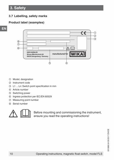
Model, designation Instrument code L1 ... Ln: Switch point specification in mm Article number Switching power Ingress protection per IEC/EN 60529 Measuring point number Serial number
Before mounting and commissioning the instrument, ensure you read the operating instructions!
3. Safety
EN
Operating instructions, magnetic float switch, model FLS
0018
88.0
4 05
/201
7 EN
/DE
11
4. Transport, packaging and storage
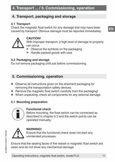
4.1 TransportCheck the magnetic float switch for any damage that may have been caused by transport. Obvious damage must be reported immediately.
CAUTION!With improper transport, a high level of damage to property can occur.
▶ Observe the symbols on the packaging ▶ Handle packed goods with care
4.2 Packaging and storageDo not remove packaging until just before commissioning.
5. Commissioning, operation
■ Observe all instructions given on the shipment packaging for removing the transportation safety devices.
■ Remove the magnetic float switch carefully from the packaging! ■ When unpacking, check all components for any external damage.
5.1 Mounting preparation
Functional checkBefore mounting, the float switch can be connected as described in chapter 5.3 and the switch points can be operated manually.
WARNING!Ensure that the functional check does not start any unintended processes.
Ensure that the sealing faces of the vessel or magnetic float switch are clean and do not show any mechanical damage.
4. Transport ... / 5. Commissioning, operation
≤ 30°
EN
0018
88.0
4 05
/201
7 EN
/DE
12 Operating instructions, magnetic float switch, model FLS
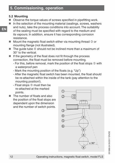
5.2 Mounting ■ Observe the torque values of screws specified in pipefitting work. ■ In the selection of the mounting material (sealings, screws, washers
and nuts), take the process conditions into account. The suitability of the sealing must be specified with regard to the medium and its vapours. In addition, ensure it has corresponding corrosion resistance.
■ Mount the magnetic float switch either via mounting thread or mounting flange (not illustrated).
■ The guide tube should not be inclined more than a maximum of 30° to the vertical.
■ If the geometry of the float does not fit through the process connection, the float must be removed before mounting.- For this, before removal, mark the position of the float stops with
a waterproof pen- Mark the mounting position of the floats (e.g. “Up”)- After the magnetic float switch has been mounted, the float should
be re-attached within the inside of the tank (pay attention to the mounting position!).
- Float stops must then be re-attached at the marked points.
■ The number of floats and also the position of the float stops are dependent upon the dimension and the number of switch points.
5. Commissioning, operation

EN
Operating instructions, magnetic float switch, model FLS
0018
88.0
4 05
/201
7 EN
/DE
13
5.3 Electrical connection ■ The electrical connection must only be made by qualified skilled
personnel. ■ Connection details and switching functions are given on the
connection diagram on the instrument and the connection terminals are appropriately marked (exception: Versions with only one normally closed or normally open contact).
■ Seal the cable bushing at the connection housing . ■ The mains connection lines to be provided must be dimensioned
for maximum instrument current supply and comply with IEC 227 or IEC 245.
WARNING!Electrical connection errors of the magnetic float switches can destroy the reed contacts. This can lead to a malfunction in the plant and thus lead to injury to personnel or damage to equipment.
▶ No direct operation in circuits with inductive loads. ▶ No direct operation in circuits with capacitive loads, e.g.
PLC, PCS or cable lengths > 50 m. ▶ Do not exceed the permissible switching power.
Connection with inductive loadWith inductive loads, the magnetic float switches should be protected by connection to an RC element or a free-wheeling diode.
For RC element see table
S1
AC 24 ... 230 VR
C
S1
DC 24 ... 250 V
+
–
AC voltage DC voltage
Free-wheeling diode, e.g. 1N4007
5. Commissioning, operation

EN
0018
88.0
4 05
/201
7 EN
/DE
14 Operating instructions, magnetic float switch, model FLS
Protective RC elementsDepending on the operating voltage, use RC elements exclusively in accordance with the table below. RC elements other than those specified here will lead to the destruction of the reed switch.
RC elements for reed contacts 10 ... 40 VAVoltage Resistance Capacitance Type of RC elementAC 24 V 100 Ω 0.33 μF A 3/24AC 48 V 220 Ω 0.33 μF A 3/48AC 115 V 470 Ω 0.33 μF A 3/115AC 230 V 1,500 Ω 0.33 μF A 3/230
RC elements for reed contacts 40 ... 100 VAVoltage Resistance Capacitance Type of RC elementAC 24 V 47 Ω 0.33 μF B 3/24AC 48 V 100 Ω 0.33 μF B 3/48AC 115 V 470 Ω 0.33 μF B 3/115AC 230 V 1,000 Ω 0.33 μF B 3/230
Connection with capacitive load
RS = 220 Ω (for AC 230 V)C₁ = internal capacitance
S1 R S+
–
C1AC 230 V
AC voltage current limitatione.g. for electronic time relay
Relay
RS = 22 Ω (47 Ω for contacts ≤ 10 VA)C₁ = internal capacitance
S1 RS+
–
C1DC 24 V
Current limitation, DC voltagee.g. for PLC, PCS and cables > 50 m
PLC
5. Commissioning, operation
EN
Operating instructions, magnetic float switch, model FLS
0018
88.0
4 05
/201
7 EN
/DE
15
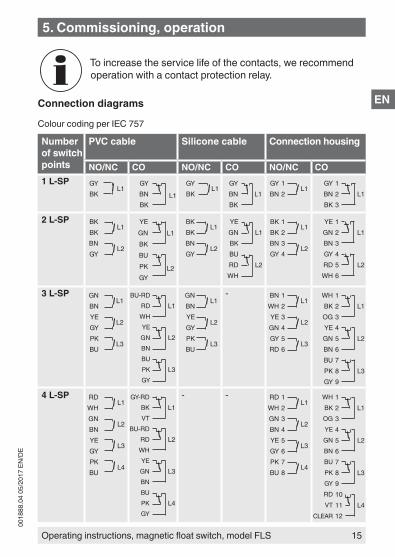
To increase the service life of the contacts, we recommend operation with a contact protection relay.
Connection diagrams
Colour coding per IEC 757
Number of switch points
PVC cable Silicone cable Connection housing
NO/NC CO NO/NC CO NO/NC CO1 L-SP GY
L1BK
GY
L1BNBK
GYL1
BKGY
L1BNBK
GY 1L1
BN 2GY 1
L1BN 2BK 3
2 L-SP BKL1
BKBN
L2GY
YEL1GN
BKBU
L2PKGY
BKL1
BKBN
L2GY
YEL1GN
BKBU
L2RDWH
BK 1L1
BK 2BN 3
L2GY 4
YE 1L1GN 2
BN 3GY 4
L2RD 5WH 6
3 L-SP GNL1
BNYE
L2GYPK
L3BU
BU-RDL1RD
WHYE
L2GNBNBU
L3PKGY
GNL1
BNYE
L2GYPK
L3BU
- BN 1L1
WH 2YE 3
L2GN 4GY 5
L3RD 6
WH 1L1BK 2
OG 3YE 4
L2GN 5BN 6BU 7
L3PK 8GY 9
4 L-SP RDL1
WHGN
L2BNYE
L3GYPK
L4BU
GY-RDL1BK
VTBU-RD
L2RDWHYE
L3GNBNBU
L4PKGY
- - RD 1L1
WH 2GN 3
L2BN 4YE 5
L3GY 6PK 7
L4BU 8
WH 1L1BK 2
OG 3YE 4
L2GN 5BN 6BU 7
L3PK 8GY 9RD 10
L4VT 11CLEAR 12
5. Commissioning, operation
EN
0018
88.0
4 05
/201
7 EN
/DE
16 Operating instructions, magnetic float switch, model FLS
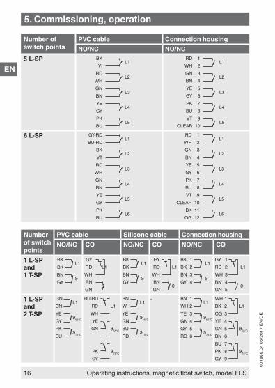
Number of switch points
PVC cable Connection housingNO/NC NO/NC
5 L-SP BKL1
VIRD
L2WHGN
L3BNYE
L4GYPK
L5BU
RD 1L1
WH 2GN 3
L2BN 4YE 5
L3GY 6PK 7
L4BU 8VT 9
L5CLEAR 10
6 L-SP GY-RDL1
BU-RDBK
L2VTRD
L3WHGN
L4BNYE
L5GYPK
L6BU
RD 1L1
WH 2GN 3
L2BN 4YE 5
L3GY 6PK 7
L4BU 8VT 9
L5CLEAR 10
BK 11L6
OG 12
Number of switch points
PVC cable Silicone cable Connection housingNO/NC CO NO/NC CO NO/NC CO
1 L-SP and 1 T-SP
BKL1
BKBN
ϑGY
GYL1RD
WHBN
ϑGN
BKL1
BKBN
ϑGY
GYL1RD
WHBN
ϑGN
BK 1L1
BK 2BN 3
ϑGY 4
GY 1L1RD 2
WH 3BN 4
ϑGN 5
1 L-SP and 2 T-SP
GNL1
BNYE
ϑ55°CGYPK
ϑ75°CBU
BU-RDL1RD
WHYE
ϑ55°CGN
ϑ75°CPKGY
BNL1
WHYE
ϑ55°CGNBU
ϑ75°CRD
- BN 1L1
WH 2YE 3
ϑ55°CGN 4GY 5
ϑ75°CRD 6
WH 1L1BK 2
OG 3YE 4
ϑ55°CGN 5BN 6BU 7
ϑ75°CPK 8GY 9
5. Commissioning, operation
EN
Operating instructions, magnetic float switch, model FLS
0018
88.0
4 05
/201
7 EN
/DE
17
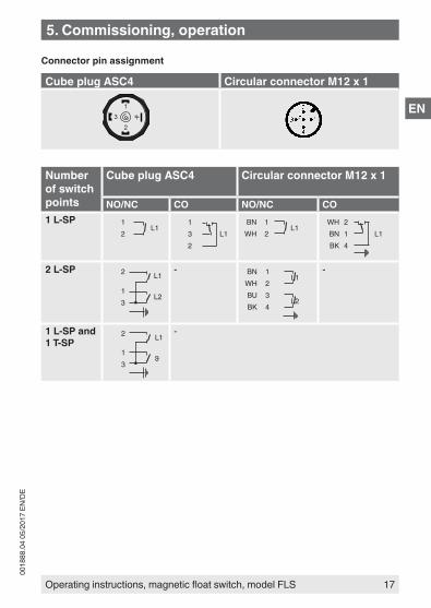
Connector pin assignment
Cube plug ASC4 Circular connector M12 x 1
1
23
Number of switch points
Cube plug ASC4 Circular connector M12 x 1
NO/NC CO NO/NC CO1 L-SP 1
L12
1L13
2
BN 1L1
WH 2WH 2
L1BN 1BK 4
2 L-SP 2 L1
1L2
3
- BN 1L1
WH 2BU 3
L2BK 4
-
1 L-SP and 1 T-SP
2 L1
1ϑ
3
-
5. Commissioning, operation
EN
0018
88.0
4 05
/201
7 EN
/DE
18 Operating instructions, magnetic float switch, model FLS
5.4 CommissioningSwitch on the voltage supply of the connected control device. Fill the vessel and the check the switch points of the magnetic float switch for function.
WARNING!Ensure that the functional check does not start any unintended processes.
Always observe the mounting and operating instructions of accessories when commissioning them.
6. Faults
The following table contains the most frequent causes of faults and the necessary countermeasures.
Faults Causes MeasuresMagnetic float switch cannot be mounted at the planned place on the vessel
Process connection of the magnetic float switch does not match the process connection of the vessel.
Modification of the vesselReturn to the factory
Process connection at the vessel defective
Rework the thread or replace the screwed coupling
Mounting thread at the magnetic float switch defective
Return to the factory
No or undefined switching function
Electrical connection incorrect
See chapter 5.3 “Electrical connection”. Check assignment with the aid of the connection diagram.
Temperature contact defective
Return to the factory
Reed contact defective
5. Commissioning, operation / 6. Faults

EN
Operating instructions, magnetic float switch, model FLS
0018
88.0
4 05
/201
7 EN
/DE
19
CAUTION!Physical injuries and damage to property and the environmentIf faults cannot be eliminated by means of the listed measures, the instrument must be taken out of operation immediately.
▶ Ensure that there is no longer any pressure present and protect against being put into operation accidentally.
▶ Contact the manufacturer. ▶ If a return is needed, please follow the instructions given
in chapter 8.2 “Return”.
7. Maintenance and cleaning
7.1 MaintenanceWhen used properly, the magnetic float switches work maintenance-free. They must be subjected to visual inspection within the context of regular maintenance, however, and included in the vessel pressure test.
DANGER!Work on vessels involves the danger of intoxication and suffocation. No work is allowed to be carried out unless by taking suitable personal protective measures (e.g. respiratory protection apparatus, protective outfit etc.).
Repairs must only be carried out by the manufacturer.
Perfect functioning of the magnetic float switches can only be guaranteed when original accessories and spare parts are used.
6. Faults / 7. Maintenance and cleaning
EN
0018
88.0
4 05
/201
7 EN
/DE
20 Operating instructions, magnetic float switch, model FLS
7.2 Cleaning
CAUTION!Physical injuries and damage to property and the environmentImproper cleaning may lead to physical injuries and damage to property and the environment. Residual media in the dismounted instrument can result in a risk to persons, the environment and equipment.
▶ Rinse or clean the removed instrument. ▶ Sufficient precautionary measures must be taken.
1. Prior to cleaning, properly disconnect the instrument from the process and the power supply.
2. Clean the instrument carefully with a moist cloth.3. Electrical connections must not come into contact with moisture!
CAUTION!Damage to propertyImproper cleaning may lead to damage to the instrument!
▶ Do not use any aggressive cleaning agents. ▶ Do not use any pointed and hard objects for cleaning.
7. Maintenance and cleaning
EN
Operating instructions, magnetic float switch, model FLS
0018
88.0
4 05
/201
7 EN
/DE
21
8. Dismounting, return and disposal
WARNING!Physical injuries and damage to property and the environment through residual mediaResidual media in the dismounted instrument can result in a risk to persons, the environment and equipment.
▶ Wash or clean the dismounted instrument, in order to protect persons and the environment from exposure to residual media.
8.1 DismountingOnly disconnect the measuring instrument once the system has been depressurised and the power disconnected!
8.2 ReturnWash or clean the dismounted magnetic float switch before returning it, in order to protect personnel and the environment from exposure to residual media.
Information on returns can be found under the heading “Service” on our local website.
8.3 DisposalIncorrect disposal can put the environment at risk.Dispose of instrument components and packaging materials in an environmentally compatible way and in accordance with the country-specific waste disposal regulations.
8. Dismounting, return and disposal
EN
0018
88.0
4 05
/201
7 EN
/DE
22 Operating instructions, magnetic float switch, model FLS
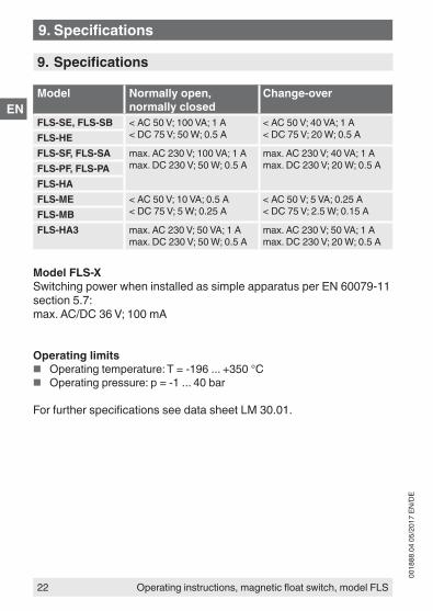
9. Specifications
Model Normally open, normally closed
Change-over
FLS-SE, FLS-SB < AC 50 V; 100 VA; 1 A< DC 75 V; 50 W; 0.5 A
< AC 50 V; 40 VA; 1 A< DC 75 V; 20 W; 0.5 AFLS-HE
FLS-SF, FLS-SA max. AC 230 V; 100 VA; 1 Amax. DC 230 V; 50 W; 0.5 A
max. AC 230 V; 40 VA; 1 Amax. DC 230 V; 20 W; 0.5 AFLS-PF, FLS-PA
FLS-HAFLS-ME < AC 50 V; 10 VA; 0.5 A
< DC 75 V; 5 W; 0.25 A< AC 50 V; 5 VA; 0.25 A< DC 75 V; 2.5 W; 0.15 AFLS-MB
FLS-HA3 max. AC 230 V; 50 VA; 1 Amax. DC 230 V; 50 W; 0.5 A
max. AC 230 V; 50 VA; 1 Amax. DC 230 V; 20 W; 0.5 A
Model FLS-XSwitching power when installed as simple apparatus per EN 60079-11 section 5.7:max. AC/DC 36 V; 100 mA
Operating limits ■ Operating temperature: T = -196 ... +350 °C ■ Operating pressure: p = -1 ... 40 bar
For further specifications see data sheet LM 30.01.
9. Specifications
DE
Betriebsanleitung Schwimmer-Magnetschalter, Typ FLS
0018
88.0
4 05
/201
7 EN
/DE
23
Konformitätserklärungen finden Sie online unter www.wika.de.
Inhalt
Inhalt1. Allgemeines 242. Aufbau und Funktion 253. Sicherheit 264. Transport, Verpackung und Lagerung 315. Inbetriebnahme, Betrieb 316. Störungen 387. Wartung und Reinigung 398. Demontage, Rücksendung und Entsorgung 419. Technische Daten 42

DE
0018
88.0
4 05
/201
7 EN
/DE
24 Betriebsanleitung Schwimmer-Magnetschalter, Typ FLS
1. Allgemeines
■ Die in der Betriebsanleitung beschriebenen Schwimmer-Magnet-schalter werden nach dem aktuellen Stand der Technik konstruiert und gefertigt. Alle Komponenten unterliegen während der Fertigung strengen Qualitäts- und Umweltkriterien. Unsere Managementsyste-me sind nach ISO 9001 zertifiziert.
■ Diese Betriebsanleitung gibt wichtige Hinweise zum Umgang mit dem Gerät. Voraussetzung für sicheres Arbeiten ist die Einhaltung aller angegebenen Sicherheitshinweise und Handlungsanweisungen.
■ Die für den Einsatzbereich des Gerätes geltenden örtlichen Unfall-verhütungsvorschriften und allgemeinen Sicherheitsbestimmungen einhalten.
■ Die Betriebsanleitung ist Produktbestandteil und muss in unmittel-barer Nähe des Gerätes für das Fachpersonal jederzeit zugänglich aufbewahrt werden. Betriebsanleitung an nachfolgende Benutzer oder Besitzer des Gerätes weitergeben.
■ Das Fachpersonal muss die Betriebsanleitung vor Beginn aller Arbei-ten sorgfältig durchgelesen und verstanden haben.
■ Es gelten die allgemeinen Geschäftsbedingungen in den Verkaufsun-terlagen.
■ Technische Änderungen vorbehalten.
■ Weitere Informationen:- Internet-Adresse: www.wika.de / www.wika.com- Zugehöriges Datenblatt: LM 30.01
Abkürzungen, DefinitionenL-SP Niveau-SchaltpunktT-SP Temperatur-SchaltpunktNO/NC Schließer/ÖffnerCO Umschalter
1. Allgemeines
≤ 30°
DE
Betriebsanleitung Schwimmer-Magnetschalter, Typ FLS
0018
88.0
4 05
/201
7 EN
/DE
25
2. Aufbau und Funktion
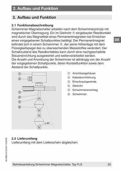
2.1 FunktionsbeschreibungSchwimmer-Magnetschalter arbeiten nach dem Schwimmerprinzip mit magnetischer Übertragung. Ein im Gleitrohr eingebauter Reedkontakt wird durch das Magnetfeld eines Permanentmagneten bei Erreichen eines vorgegebenen Schaltpunktes betätigt. Der Permanentmagnet befindet sich in einem Schwimmer , der seine Höhenlage mit dem Flüssigkeitspegel des zu überwachenden Messstoffes verändert. Der Schaltzustand des Reedkontaktes kann durch eine nachgeschaltete Steuereinrichtung ausgewertet und weiterverarbeitet werden.Die Anzahl und Anordnung der Schwimmer ist abhängig von der Anzahl der vorgegebenen Schaltpunkte, deren Kontaktfunktion sowie dem Abstand der Schaltpunkte.
Anschlussgehäuse Kabeldurchführung Einschraubgewinde Gleitrohr Schwimmeranschlag Schwimmer
2.2 LieferumfangLieferumfang mit dem Lieferschein abgleichen.
2. Aufbau und Funktion
DE
0018
88.0
4 05
/201
7 EN
/DE
26 Betriebsanleitung Schwimmer-Magnetschalter, Typ FLS
3. Sicherheit
3.1 Symbolerklärung
GEFAHR!... weist auf eine unmittelbar gefährliche Situation hin, die zum Tod oder zu schweren Verletzungen führt, wenn sie nicht gemieden wird.
WARNUNG!... weist auf eine möglicherweise gefährliche Situation hin, die zum Tod oder zu schweren Verletzungen führen kann, wenn sie nicht gemieden wird.
VORSICHT!... weist auf eine möglicherweise gefährliche Situation hin, die zu geringfügigen oder leichten Verletzungen bzw. Sach- und Umweltschäden führen kann, wenn sie nicht gemieden wird.
Information... hebt nützliche Tipps und Empfehlungen sowie Informatio-nen für einen effizienten und störungsfreien Betrieb hervor.
3.2 Bestimmungsgemäße VerwendungSchwimmer-Magnetschalter dienen ausschließlich der Füllstandsüber-wachung von flüssigen Messstoffen. Der Einsatzbereich ergibt sich aus den technischen Leistungsgrenzen und Werkstoffen.
■ Die Flüssigkeiten dürfen keine starken Verschmutzungen oder Grobteile aufweisen und nicht zum Auskristallisieren neigen. Es ist sicherzustellen, dass die medienberührenden Werkstoffe des Schwimmer-Magnetschalters gegen den zu überwachenden Messstoff ausreichend beständig sind. Nicht geeignet für Dispersio-nen, abrasive Flüssigkeiten, hochviskose Medien und Farben.
3. Sicherheit
DE
Betriebsanleitung Schwimmer-Magnetschalter, Typ FLS
0018
88.0
4 05
/201
7 EN
/DE
27
■ Dieses Gerät ist nicht für den Einsatz in explosionsgefährdeten Bereichen zugelassen! Ausgenommen sind Schwimmer-Magnetschalter, die als einfaches elektrisches Betriebsmittel gemäß EN 60079-11 Abschnitt 5.7 gekennzeichnet sind.
■ Die in der Betriebsanleitung angegebenen Einsatzbedingungen sind einzuhalten.
■ Gerät nicht in unmittelbarer Nähe von ferromagnetischer Umgebung (Abstand min. 50 mm) betreiben.
■ Gerät nicht in unmittelbarer Nähe von starken elektromagnetischen Feldern bzw. in unmittelbarer Nähe von Einrichtungen betreiben, die durch Magnetfelder beeinflusst werden können (Abstand min. 1 m).
■ Die Schwimmer-Magnetschalter dürfen keinen starken mecha-nischen Belastungen (Stoß, Verbiegen, Vibrationen) ausgesetzt werden.
■ Die technischen Spezifikationen in dieser Betriebsanleitung sind einzuhalten. Eine unsachgemäße Handhabung oder ein Betreiben des Gerätes außerhalb der technischen Spezifikationen macht die sofortige Stilllegung und Überprüfung durch einen autorisierten WIKA-Servicemitarbeiter erforderlich.
Das Gerät ist ausschließlich für den hier beschriebenen bestimmungs-gemäßen Verwendungszweck konzipiert und konstruiert und darf nur dementsprechend verwendet werden.
Ansprüche jeglicher Art aufgrund von nicht bestimmungsgemäßer Verwendung sind ausgeschlossen.
GEFAHR!Beim Arbeiten an Behältern, besteht Vergiftungs- oder Erstickungsgefahr. Arbeiten dürfen nur unter Anwendung geeigneter Personenschutzmaßnahmen (z. B. Atemschutz-gerät, Schutzkleidung o. Ä.). durchgeführt werden.
3. Sicherheit
DE
0018
88.0
4 05
/201
7 EN
/DE
28 Betriebsanleitung Schwimmer-Magnetschalter, Typ FLS
3.3 FehlgebrauchAls Fehlgebrauch gilt jede Verwendung, die die technischen Leistungs-grenzen überschreitet oder mit den Werkstoffen unverträglich ist.
WARNUNG!Verletzungen durch FehlgebrauchFehlgebrauch des Gerätes kann zu gefährlichen Situationen und Verletzungen führen.
▶ Eigenmächtige Umbauten am Gerät unterlassen. ▶ Gerät nicht in explosionsgefährdeten Bereichen einset-
zen.
Jede über die bestimmungsgemäße Verwendung hinausgehende oder andersartige Benutzung gilt als Fehlgebrauch.
Dieses Gerät nicht in Sicherheits- oder in Not-Aus-Einrichtungen benut-zen.
3.4 Verantwortung des BetreibersDas Gerät wird im gewerblichen Bereich eingesetzt. Der Betreiber unter-liegt daher den gesetzlichen Pflichten zur Arbeitssicherheit.
Die Sicherheitshinweise dieser Betriebsanleitung, sowie die für den Einsatzbereich des Gerätes gültigen Sicherheits-, Unfallverhütungs- und Umweltschutzvorschriften einhalten.
Für ein sicheres Arbeiten am Gerät muss der Betreiber Folgendes sicherstellen:
■ Bedienpersonal wird regelmäßig in allen zutreffenden Fragen von Arbeitssicherheit, Erste Hilfe und Umweltschutz unterwiesen.
■ Bedienpersonal hat Betriebsanleitung gelesen und insbesondere die darin enthaltenen Sicherheitshinweise zur Kenntnis genommen.
■ Die bestimmungsgemäße Verwendung für den Anwendungsfall wird eingehalten.
■ Nach Prüfung ist ein Fehlgebrauch des Gerätes ausgeschlossen.
3. Sicherheit
DE
Betriebsanleitung Schwimmer-Magnetschalter, Typ FLS
0018
88.0
4 05
/201
7 EN
/DE
29
3.5 Personalqualifikation
WARNUNG!Verletzungsgefahr bei unzureichender QualifikationUnsachgemäßer Umgang kann zu erheblichen Personen- und Sachschäden führen.
▶ Die in dieser Betriebsanleitung beschriebenen Tätigkeit-en nur durch Fachpersonal nachfolgend beschriebener Qualifikation durchführen lassen.
FachpersonalDas vom Betreiber autorisierte Fachpersonal ist aufgrund seiner fachlichen Ausbildung, seiner Kenntnisse der Mess- und Regelungs-technik und seiner Erfahrungen sowie Kenntnis der landesspezifi-schen Vorschriften, geltenden Normen und Richtlinien in der Lage, die beschriebenen Arbeiten auszuführen und mögliche Gefahren selbststän-dig zu erkennen.
3.6 Persönliche SchutzausrüstungDie persönliche Schutzausrüstung dient dazu, das Fachpersonal gegen Gefahren zu schützen, die dessen Sicherheit oder Gesundheit bei der Arbeit beeinträchtigen könnten. Beim Ausführen der verschiedenen Arbeiten an und mit dem Gerät muss das Fachpersonal persönliche Schutzausrüstung tragen.
Im Arbeitsbereich angebrachte Hinweise zur persönlichen Schutz-ausrüstung befolgen!
Die erforderliche persönliche Schutzausrüstung muss vom Betreiber zur Verfügung gestellt werden.
3. Sicherheit
DE
0018
88.0
4 05
/201
7 EN
/DE
30 Betriebsanleitung Schwimmer-Magnetschalter, Typ FLS
3.7 Beschilderung, Sicherheitskennzeichnungen
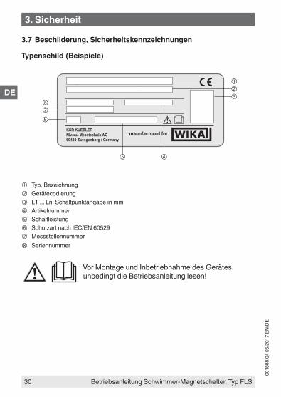
Typenschild (Beispiele)
3. Sicherheit
Type: ARV2"-VU-L1100/12-V52A
Ser. No.: 200012A1 Art. No.: 210215
L1: 250L2: 350L3: 690L4:L5:
Tag No.:
IP65 max. AC/DC 250 V
Magnetic float switch FLS-SA
KSR KUEBLERNiveau-Messtechnik AG69439 Zwingenberg / Germany
manufactured for
Typ, Bezeichnung Gerätecodierung L1 ... Ln: Schaltpunktangabe in mm Artikelnummer Schaltleistung Schutzart nach IEC/EN 60529 Messstellennummer Seriennummer
Vor Montage und Inbetriebnahme des Gerätes unbedingt die Betriebsanleitung lesen!
DE
Betriebsanleitung Schwimmer-Magnetschalter, Typ FLS
0018
88.0
4 05
/201
7 EN
/DE
31
4. Transport, Verpackung und Lagerung
4.1 TransportSchwimmer-Magnetschalter auf eventuell vorhandene Transportschäden untersuchen. Offensichtliche Schäden unverzüglich mitteilen.
VORSICHT!Bei unsachgemäßem Transport können Sachschäden in erheblicher Höhe entstehen.
▶ Symbole auf der Verpackung beachten ▶ Packstücke vorsichtig behandeln
4.2 Verpackung und LagerungVerpackung erst unmittelbar vor der Inbetriebnahme entfernen.
5. Inbetriebnahme, Betrieb
■ Alle auf der Versandverpackung angegebenen Hinweise zum Entfernen der Transportsicherungen beachten.
■ Den Schwimmer-Magnetschalter vorsichtig aus der Verpackung entnehmen!
■ Beim Auspacken alle Teile auf äußerliche Beschädigungen überprüfen.
5.1 Montagevorbereitung
FunktionsprüfungVor der Montage kann der Schwimmerschalter wie unter Kapitel 5.3 beschrieben angeschlossen und die Schaltpunk-te manuell betätigt werden.
WARNUNG!Sicherstellen, dass die Funktionsprüfung keine unbeabsich-tigten Prozesse startet.
Sicherstellen, dass die Dichtflächen des Behälters bzw. des Schwimmer-Magnetschalters sauber sind und keine mechanische Beschädigung aufweisen.
4. Transport ... / 5. Inbetriebnahme, Betrieb
DE
0018
88.0
4 05
/201
7 EN
/DE
32 Betriebsanleitung Schwimmer-Magnetschalter, Typ FLS
5.2 Montage ■ Die im Rohrleitungsbau vorgeschriebenen Drehmomentwerte der
Schrauben einhalten. ■ Bei der Auswahl des Montagematerials (Dichtungen, Schrauben,
Unterlegscheiben und Muttern) die Prozessbedingungen beachten. Die Eignung der Dichtung muss hinsichtlich Messstoff und dessen Dämpfen gegeben sein. Zusätzlich ist auf entsprechende Korrosions-beständigkeit zu achten.
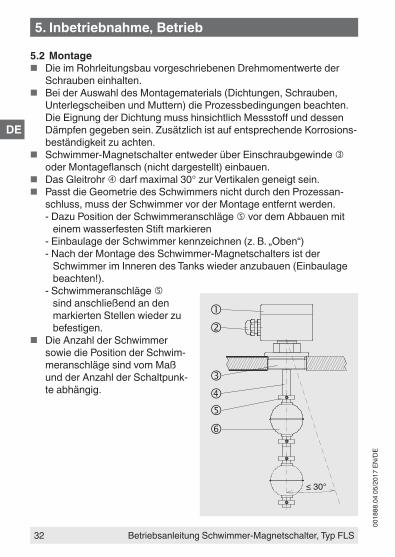
■ Schwimmer-Magnetschalter entweder über Einschraubgewinde oder Montageflansch (nicht dargestellt) einbauen.
■ Das Gleitrohr darf maximal 30° zur Vertikalen geneigt sein. ■ Passt die Geometrie des Schwimmers nicht durch den Prozessan-
schluss, muss der Schwimmer vor der Montage entfernt werden.- Dazu Position der Schwimmeranschläge vor dem Abbauen mit
einem wasserfesten Stift markieren- Einbaulage der Schwimmer kennzeichnen (z. B. „Oben“)- Nach der Montage des Schwimmer-Magnetschalters ist der
Schwimmer im Inneren des Tanks wieder anzubauen (Einbaulage beachten!).
- Schwimmeranschläge sind anschließend an den markierten Stellen wieder zu befestigen.
■ Die Anzahl der Schwimmer sowie die Position der Schwim-meranschläge sind vom Maß und der Anzahl der Schaltpunk-te abhängig.
≤ 30°
5. Inbetriebnahme, Betrieb
DE
Betriebsanleitung Schwimmer-Magnetschalter, Typ FLS
0018
88.0
4 05
/201
7 EN
/DE
33
5.3 Elektrischer Anschluss ■ Der elektrische Anschluss darf nur durch qualifiziertes Fachpersonal
erfolgen. ■ Die Belegung der Anschlüsse und die Schaltfunktionen sind auf dem
Anschlussschema am Gerät angegeben und die Anschlussklemmen sind entsprechend gekennzeichnet (Ausnahme: Ausführungen mit nur einem Öffner- oder Schließerkontakt).
■ Die Kabeldurchführung am Anschlussgehäuse abdichten. ■ Die vorgesehenen Netzanschlussleitungen müssen für die größte
Stromaufnahme des Gerätes bemessen sein und IEC 227 oder IEC 245 entsprechen.
WARNUNG!Fehler beim elektrischen Anschluss von Schwimmer-Magnetschaltern können die Reedkontakte zerstören. Dies kann zu einer Fehlfunktion der Anlage und dadurch zu Personen- oder Sachschäden führen.
▶ Kein direkter Betrieb an Schaltungen mit induktiver Last. ▶ Kein direkter Betrieb an Schaltungen mit kapazitiver Last,
z. B. SPS, PLS oder Leitungslängen > 50 m. ▶ Kein Überschreiten der zulässigen Schaltleistung.
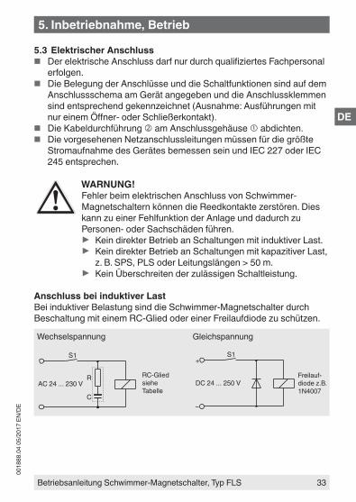
Anschluss bei induktiver LastBei induktiver Belastung sind die Schwimmer-Magnetschalter durch Beschaltung mit einem RC-Glied oder einer Freilaufdiode zu schützen.
RC-Glied siehe Tabelle
S1
AC 24 ... 230 VR
C
S1
DC 24 ... 250 V
+
–
Wechselspannung Gleichspannung
Freilauf-diode z.B. 1N4007
5. Inbetriebnahme, Betrieb
DE
0018
88.0
4 05
/201
7 EN
/DE
34 Betriebsanleitung Schwimmer-Magnetschalter, Typ FLS
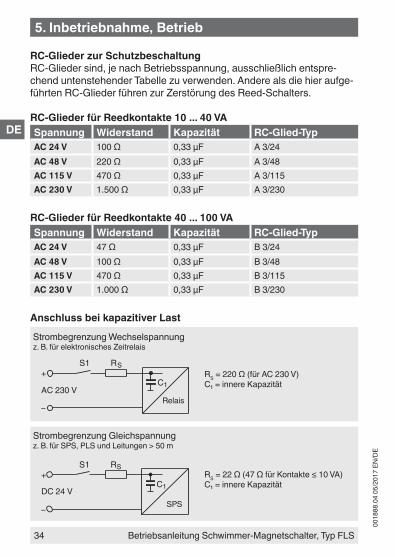
RC-Glieder zur Schutzbeschaltung RC-Glieder sind, je nach Betriebsspannung, ausschließlich entspre-chend untenstehender Tabelle zu verwenden. Andere als die hier aufge-führten RC-Glieder führen zur Zerstörung des Reed-Schalters.
RC-Glieder für Reedkontakte 10 ... 40 VASpannung Widerstand Kapazität RC-Glied-TypAC 24 V 100 Ω 0,33 μF A 3/24AC 48 V 220 Ω 0,33 μF A 3/48AC 115 V 470 Ω 0,33 μF A 3/115AC 230 V 1.500 Ω 0,33 μF A 3/230
RC-Glieder für Reedkontakte 40 ... 100 VASpannung Widerstand Kapazität RC-Glied-TypAC 24 V 47 Ω 0,33 μF B 3/24AC 48 V 100 Ω 0,33 μF B 3/48AC 115 V 470 Ω 0,33 μF B 3/115AC 230 V 1.000 Ω 0,33 μF B 3/230
Anschluss bei kapazitiver Last
RS = 220 Ω (für AC 230 V)C₁ = innere Kapazität
S1 R S+
–
C1AC 230 V
Strombegrenzung Wechselspannungz. B. für elektronisches Zeitrelais
Relais
RS = 22 Ω (47 Ω für Kontakte ≤ 10 VA)C₁ = innere Kapazität
S1 RS+
–
C1DC 24 V
Strombegrenzung Gleichspannungz. B. für SPS, PLS und Leitungen > 50 m
SPS
5. Inbetriebnahme, Betrieb
DE
Betriebsanleitung Schwimmer-Magnetschalter, Typ FLS
0018
88.0
4 05
/201
7 EN
/DE
35
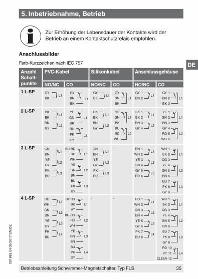
Zur Erhöhung der Lebensdauer der Kontakte wird der Betrieb an einem Kontaktschutzrelais empfohlen.
AnschlussbilderFarb-Kurzzeichen nach IEC 757
Anzahl Schalt-punkte
PVC-Kabel Silikonkabel Anschlussgehäuse
NO/NC CO NO/NC CO NO/NC CO1 L-SP GY
L1BK
GY
L1BNBK
GYL1
BKGY
L1BNBK
GY 1L1
BN 2GY 1
L1BN 2BK 3
2 L-SP BKL1
BKBN
L2GY
YEL1GN
BKBU
L2PKGY
BKL1
BKBN
L2GY
YEL1GN
BKBU
L2RDWH
BK 1L1
BK 2BN 3
L2GY 4
YE 1L1GN 2
BN 3GY 4
L2RD 5WH 6
3 L-SP GNL1
BNYE
L2GYPK
L3BU
BU-RDL1RD
WHYE
L2GNBNBU
L3PKGY
GNL1
BNYE
L2GYPK
L3BU
- BN 1L1
WH 2YE 3
L2GN 4GY 5
L3RD 6
WH 1L1BK 2
OG 3YE 4
L2GN 5BN 6BU 7
L3PK 8GY 9
4 L-SP RDL1
WHGN
L2BNYE
L3GYPK
L4BU
GY-RDL1BK
VTBU-RD
L2RDWHYE
L3GNBNBU
L4PKGY
- - RD 1L1
WH 2GN 3
L2BN 4YE 5
L3GY 6PK 7
L4BU 8
WH 1L1BK 2
OG 3YE 4
L2GN 5BN 6BU 7
L3PK 8GY 9RD 10
L4VT 11CLEAR 12
5. Inbetriebnahme, Betrieb
DE
0018
88.0
4 05
/201
7 EN
/DE
36 Betriebsanleitung Schwimmer-Magnetschalter, Typ FLS
Anzahl Schaltpunkte
PVC-Kabel AnschlussgehäuseNO/NC NO/NC
5 L-SP BKL1
VIRD
L2WHGN
L3BNYE
L4GYPK
L5BU
RD 1L1
WH 2GN 3
L2BN 4YE 5
L3GY 6PK 7
L4BU 8VT 9
L5CLEAR 10
6 L-SP GY-RDL1
BU-RDBK
L2VTRD
L3WHGN
L4BNYE
L5GYPK
L6BU
RD 1L1
WH 2GN 3
L2BN 4YE 5
L3GY 6PK 7
L4BU 8VT 9
L5CLEAR 10
BK 11L6
OG 12
Anzahl Schalt-punkte
PVC-Kabel Silikonkabel AnschlussgehäuseNO/NC CO NO/NC CO NO/NC CO
1 L-SP und 1 T-SP
BKL1
BKBN
ϑGY
GYL1RD
WHBN
ϑGN
BKL1
BKBN
ϑGY
GYL1RD
WHBN
ϑGN
BK 1L1
BK 2BN 3
ϑGY 4
GY 1L1RD 2
WH 3BN 4
ϑGN 5
1 L-SP und 2 T-SP
GNL1
BNYE
ϑ55°CGYPK
ϑ75°CBU
BU-RDL1RD
WHYE
ϑ55°CGN
ϑ75°CPKGY
BNL1
WHYE
ϑ55°CGNBU
ϑ75°CRD
- BN 1L1
WH 2YE 3
ϑ55°CGN 4GY 5
ϑ75°CRD 6
WH 1L1BK 2
OG 3YE 4
ϑ55°CGN 5BN 6BU 7
ϑ75°CPK 8GY 9
5. Inbetriebnahme, Betrieb
DE
Betriebsanleitung Schwimmer-Magnetschalter, Typ FLS
0018
88.0
4 05
/201
7 EN
/DE
37
Pinbelegung Stecker
Würfelstecker ASC4 Rundstecker M12 x 1
1
23
Anzahl Schalt-punkte
Würfelstecker ASC4 Rundstecker M12 x 1
NO/NC CO NO/NC CO1 L-SP 1
L12
1L13
2
BN 1L1
WH 2WH 2
L1BN 1BK 4
2 L-SP 2 L1
1L2
3
- BN 1L1
WH 2BU 3
L2BK 4
-
1 L-SP und 1 T-SP
2 L1
1ϑ
3
-
5. Inbetriebnahme, Betrieb
DE
0018
88.0
4 05
/201
7 EN
/DE
38 Betriebsanleitung Schwimmer-Magnetschalter, Typ FLS
5.4 InbetriebnahmeSpannungsversorgung der angeschlossenen Steuerungseinrichtung einschalten. Behälter füllen und die Schaltpunkte des Schwimmer-Magnetschalters auf Funktion prüfen.
WARNUNG!Sicherstellen, dass die Funktionsprüfung keine unbeabsich-tigten Prozesse startet.
Zur Inbetriebnahme von Zubehör unbedingt die jeweilige Montage- und Betriebsanleitung beachten.
6. Störungen
In der folgenden Tabelle sind die häufigsten Fehlerursachen und erforderliche Gegenmaßnahmen aufgeführt.
Störungen Ursachen MaßnahmenSchwimmer-Magnet-schalter lässt sich nicht an der vorge-sehenen Stelle am Behälter anbauen
Prozessanschluss des Schwimmer-Magnetschalters passt nicht zu dem Prozess-anschluss des Behälters.
Umbau des BehältersRücksendung ans Werk
Prozessanschluss am Behäl-ter defekt
Nacharbeiten des Gewin-des oder Austauschen der Befestigungsmuffe
Einschraubgewinde am Schwimmer-Magnetschalter defekt
Rücksendung ans Werk
Keine oder undefi-nierte Schaltfunktion
Elektrischer Anschluss falsch
Siehe Kapitel 5.3 „Elektrischer Anschluss“. Belegung mit Hilfe des Anschlussbildes prüfen.
Temperaturkontakt defekt Rücksendung ans WerkReed-Kontakt defekt
5. Inbetriebnahme, Betrieb / 6. Störungen
DE
Betriebsanleitung Schwimmer-Magnetschalter, Typ FLS
0018
88.0
4 05
/201
7 EN
/DE
39
VORSICHT!Körperverletzungen, Sach- und UmweltschädenKönnen Störungen mit Hilfe der aufgeführten Maßnahmen nicht beseitigt werden, Gerät unverzüglich außer Betrieb setzen.
▶ Sicherstellen, dass kein Druck mehr anliegt und gegen versehentliche Inbetriebnahme schützen.
▶ Kontakt mit dem Hersteller aufnehmen. ▶ Bei notwendiger Rücksendung die Hinweise unter Kapitel
8.2 „Rücksendung“ beachten.
7. Wartung und Reinigung
7.1 WartungDie Schwimmer-Magnetschalter arbeiten bei bestimmungsgemäßem Gebrauch wartungsfrei. Sie sind jedoch im Rahmen der regelmäßigen Wartung einer Sichtkontrolle zu unterziehen und in die Druckprüfung des Behälters mit einzubeziehen.
GEFAHR!Beim Arbeiten an Behältern besteht Vergiftungs- oder Erstickungsgefahr. Arbeiten dürfen nur unter Anwendung geeigneter Personenschutzmaßnahmen (z. B. Atemschutz-gerät, Schutzkleidung o. Ä.). durchgeführt werden.
Reparaturen sind ausschließlich vom Hersteller durchzuführen.
Die Funktion der Schwimmer-Magnetschalter kann nur bei Verwendung von Originalzubehör und Ersatzteilen gewähr-leistet werden.
6. Störungen / 7. Wartung und Reinigung
DE
0018
88.0
4 05
/201
7 EN
/DE
40 Betriebsanleitung Schwimmer-Magnetschalter, Typ FLS
7.2 Reinigung
VORSICHT!Körperverletzungen, Sach- und UmweltschädenEine unsachgemäße Reinigung führt zu Körperverlet-zungen, Sach- und Umweltschäden. Messstoffreste im ausgebauten Gerät können zur Gefährdung von Personen, Umwelt und Einrichtung führen.
▶ Ausgebautes Gerät spülen bzw. säubern. ▶ Ausreichende Vorsichtsmaßnahmen sind zu ergreifen.
1. Vor der Reinigung das Gerät ordnungsgemäß vom Prozess und der Stromversorgung trennen.
2. Das Gerät vorsichtig mit einem feuchten Tuch reinigen.3. Elektrische Anschlüsse nicht mit Feuchtigkeit in Berührung bringen!
VORSICHT!SachbeschädigungEine unsachgemäße Reinigung führt zur Beschädigung des Gerätes!
▶ Keine aggressiven Reinigungmittel verwenden. ▶ Keine harten und spitzen Gegenstände zur Reinigung
verwenden.
7. Wartung und Reinigung

DE
Betriebsanleitung Schwimmer-Magnetschalter, Typ FLS
0018
88.0
4 05
/201
7 EN
/DE
41
8. Demontage, Rücksendung und Entsorgung
WARNUNG!Körperverletzungen, Sach- und Umweltschäden durch MessstoffresteMessstoffreste im ausgebauten Gerät können zur Gefähr-dung von Personen, Umwelt und Einrichtung führen.
▶ Ausgebautes Gerät spülen bzw. säubern, um Personen und Umwelt vor Gefährdung durch anhaftende Messstof-freste zu schützen.
8.1 DemontageMessgerät nur im drucklosen und spannungsfreiem Zustand demontieren!
8.2 RücksendungAusgebauten Schwimmer-Magnetschalter vor der Rücksendung spülen bzw. säubern, um Mitarbeiter und Umwelt vor Gefährdung durch anhaf-tende Messstoffreste zu schützen.
Hinweise zur Rücksendung befinden sich in der Rubrik „Service“ auf unserer lokalen Internetseite.
8.3 EntsorgungDurch falsche Entsorgung können Gefahren für die Umwelt entstehen.Gerätekomponenten und Verpackungsmaterialien entsprechend den landesspezifischen Abfallbehandlungs- und Entsorgungsvorschriften umweltgerecht entsorgen.
8. Demontage, Rücksendung und Entsorgung
DE
0018
88.0
4 05
/201
7 EN
/DE
42 Betriebsanleitung Schwimmer-Magnetschalter, Typ FLS
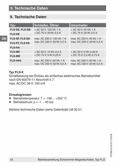
9. Technische Daten
Typ Schließer, Öffner UmschalterFLS-SE, FLS-SB < AC 50 V; 100 VA; 1 A
< DC 75 V; 50 W; 0,5 A< AC 50 V; 40 VA; 1 A< DC 75 V; 20 W; 0,5 AFLS-HE
FLS-SF, FLS-SA max. AC 230 V; 100 VA; 1 Amax. DC 230 V; 50 W; 0,5 A
max. AC 230 V; 40 VA; 1 Amax. DC 230 V; 20 W; 0,5 AFLS-PF, FLS-PA
FLS-HAFLS-ME < AC 50 V; 10 VA; 0,5 A
< DC 75 V; 5 W; 0,25 A< AC 50 V; 5 VA; 0,25 A< DC 75 V; 2,5 W; 0,15 AFLS-MB
FLS-HA3 max. AC 230 V; 50 VA; 1 Amax. DC 230 V; 50 W; 0,5 A
max. AC 230 V; 50 VA; 1 Amax. DC 230 V; 20 W; 0,5 A
Typ FLS-XSchaltleistung bei Einbau als einfaches elektrisches Betriebsmittel nach EN 60079-11 Abschnitt 5.7:max. AC/DC 36 V; 100 mA
Einsatzgrenzen ■ Betriebstemperatur: T = -196 ... +350 °C ■ Betriebsdruck: p = -1 ... 40 bar
Weitere technische Daten siehe Datenblatt LM 30.01.
9. Technische Daten

Operating instructions, magnetic float switch, model FLS
0018
88.0
4 05
/201
7 EN
/DE
43
KSR Kuebler subsidiaries worldwide can be found online at www.ksr-kuebler.com.WIKA subsidiaries worldwide can be found online at www.wika.com.
Manufacturer contact: Sales contact:
A division of the WIKA group
0018
88.0
4 05
/201
7 EN
/DE
44 Operating instructions, magnetic float switch, model FLS
WIKA Alexander Wiegand SE & Co. KGAlexander-Wiegand-Strasse 3063911 Klingenberg • GermanyTel. +49 9372 132-0Fax +49 9372 [email protected]
KSR Kuebler Niveau-Messtechnik AGHeinrich-Kuebler-Platz 169439 Zwingenberg am Neckar • GermanyTel. +49 6263/87-0Fax +49 6263/[email protected]