operating hints for using split/splitless injectorsoperating in the split injection mode when...
TRANSCRIPT
1
www.restek.com
Inside:Overviews of split and splitless injection tech niques
Backpressure-regulated injection systems
Headpressure-regulated injectionsystems
Operating in the split injection mode
Inlet liners for split injections
Operating in the splitless injection Mode
Inlet liners for splitless injections
Septum purge optimization
Problems associated with split and splitless injections
Direct injection as an alternative to splitless injection
Hints for analyzing dirty samples
Hints for performing routine injection port maintenance
Product listing
Operating Hints for Using Split/Splitless
Injectors
Technical Guide

2
www.restek.com
Overview of Split/Splitless Injection TechniquesIn capillary and micropacked gas chromatography (GC) there are four primary techniques for vaporizing a sample and transferring it onto the inlet of the analytical column: split, split-less, direct, and on-column injections. Of these, split and splitless injections are the most commonly used techniques. This technical guide focuses on split and splitless injections—their optimization, troubleshooting, and system maintenance.
Split and splitless injections are techniques that introduce the sample into a heated injection port as a liquid, and then rapidly and completely vaporize the sample solvent as well as all of the analytes in the sample. The vaporized sample is transferred to the head of the column.
In the split injection mode, only a fraction of the vaporized sample is transferred onto the head of the column. The remainder of the vaporized sample is removed from the injection port via the split vent line. Split injections should be used only when sample concentrations are high enough to allow a portion of the sample to be discarded during the injection process, while still maintaining a sufficient concentration of analytes at the detector to produce a signal.
When target analyte concentrations are so low that splitting the sample in the injection port will not allow an adequate signal from the detector, the injector should be operated in the splitless injection mode. In the splitless injection mode, most of the vaporized sample is transferred to the head of the column.
The process of performing either a split or splitless injection is controlled by changing the flow path and flow rate of carrier gas through the injection port. The position of a switch-ing valve in the injection port determines the flow path. In split injections, a high carrier gas flow rate rapidly moves the vaporized sample through the injection port liner, past the col-umn (with only a minimal amount directed to the head of the column), and out the split vent. In splitless injections, a relatively slow carrier gas flow rate directs most of the vaporized sample into the head of the column.
Split/splitless injection ports can be either backpressure-regulated or headpressure-regulated systems. Most modern GCs are backpressure regulated. However, some GC manufacturers still find headpressure regulation advantageous and use this design in their split/splitless injectors. It is important for analysts to be familiar with their injection port hardware and the operating principles of their instruments, so that they factor in the variables affecting the accuracy and reproducibility of their results.
Backpressure-Regulated Injection SystemsFigure 1 illustrates the components of a typical backpressure-regulated split/splitless injec-tion system (e.g., Agilent 5890, 6850, 6890 GCs; Varian 3300, 3400, 3500, 3600, 3800 GCs; Shimadzu 17A GCs). A flow controller, positioned upstream from the injection port, controls the total amount of carrier gas that enters the injection port. A backpressure regulator, located down-stream from the injection port body, regulates the pressure inside the injection port. Carrier gas flow rate in the column is determined by the pressure that is maintained in the injection port. The outlet of the backpressure regulator is the outlet of the split vent line. The split vent line outlet is at the ambient pressure of the laboratory. The flow controller and the backpressure regulator work together to determine the column flow rate, septum purge flow rate, and split vent flow rate.
Split and splitless injections in backpressure-regulated systems are controlled by the position of the 3-way solenoid valve. In the split injection mode, the flow path is always open from the injection port body through the 3-way solenoid valve to the split vent line. In the splitless injection mode, the flow path is temporarily closed from the injection port body to the split vent line. The carrier gas flow rate through the injection port liner is simply the column flow rate. Any excess flow is directed through the septum purge line, into the 3-way solenoid valve, and out the split vent line.
In backpressure-regulated systems, the split vent flow rate is changed by adjusting the flow controller. An increase in the total flow being delivered to the injection port will result in a higher split vent flow rate and a higher split ratio. Column flow rate is not affected by changes in the total flow being delivered to the injection port, but by the backpressure regu-lator. To maintain the same pressure at all times, use the backpressure regulator to compen-sate for a change in the total flow delivered to the injection port.
Table of ContentsOverview of Split/Splitless Injection Techniques ..................................... 2Backpressure-Regulated Injection Systems . 2Headpressure-Regulated Injection Systems ......................................... 3Operating in the Split Injection Mode ...... 4Inlet Liners for Split Injectors ................ 6Operating in the Splitless Injection Mode .. 7 Solvent Focusing and Analyte Focusing........ 9Inlet Liners for Splitless Injections ......... 11Septum Purge Optimization .................. 12Problems Associated with Split and Splitless Injections ...................................... 13. Thermal Decomposition.............................. 13. Active Compounds...................................... 13. Molecular Weight Discrimination................ 13. Needle Discrimination................................. 14. Backflash.................................................... 15. Sample Size and Injection Port Temperature............................................. 15. Optimizing the Rate of Injection.................. 16. Pressure Programming............................... 16Direct Injection as an Alternative to Splitless Injection ....................................... 16Hints for Analyzing Dirty Samples .......... 18Hints for Performing Routing Injection Port Maintenance .................................. 19. Cleaning and Deactivating Injector Liners.... 19. Replacing Critical Seals............................... 19. Changing Septa........................................... 19Product Listing .........4, 5, 9, 18, 19, 20–35. Restek Flowmeter 6000................................. 4. Soap Film Bubble Flowmeters........................ 4. Split Vent Trap............................................... 5. Methane Cylinder........................................... 5. Split and Splitless Injection in Capillary GC, 4th Ed. book......................................... 9. Mini Wool Puller/Inserter............................. 18. Nylon Tube Brushes and Pipe Cleaner......... 19. Leak Detective II Leak Detector................... 19. Siltek™ Inlet Liners....................................... 20. Base-Deactivated Inlet Liners...................... 20. Prepacked Liners........................................ 20 Liners for Agilent/Finnigan GCs.............. 21–22. O-rings........................................................ 23. Inlet & FID Maintenance Kits...................... 23. Vespel® Ring Inlet Seals for Agilent 5890/6890 and 6850 GCs......................... 24. Rethreading Tool......................................... 24. Replacement Inlet Seals.............................. 25. Replacement Inlet Cross-Disk Seal for Agilent GCs......................................... 25. Liners for Varian GCs............................ 26–27 Varian Inlet Liner Seals............................... 27. Inlet Liner Removal Tool............................. 27. Liners for PerkinElmer GCs......................... 28. Liners for Shimadzu GCs............................ 29. Liners for Thermo Finnigan GCs........... 30–31. Inlet Liner Seal for TRACE™ 2000 GCs........ 31. Graphite Sealing Ring and Washer for 8000 Series and TRACE™ GC Inlet Liners........... 31. Septa........................................................... 32. Press-Tight® Connectors............................. 33. Polyimide Resin.......................................... 33. MXT®-Union Connector Kits........................ 34. Valco® Connectors...................................... 34. Gerstel GRAPHPACK® 3D/2 Connectors..... 34. Guard Columns and Transfer Lines............ 35

3
Figure 1. Split injection flowpaths in a typical flow-controlled/backpressure-regulated system.
flow con trol ler
carrier gasinlet
injection port
o-ring or ferrule
injector liner
3-way solenoid valve
needle valve
septum purge vent
split vent
backpressure regulator
to detector
closed
A flow-controlled, backpressure-regulated system is beneficial as it gives some measure of protection against a catastrophic loss of carrier gas. If there is a leak at an injection port fit-ting or a column fitting, the maximum rate of carrier gas loss would be the total flow rate into the injection port as determined by the flow controller. Unlimited flow of carrier gas into the injection port is prevented by having the flow controller at the inlet of the injection port. Leaks are indicated by a failure to maintain split vent flow rate. A common mistake analysts make when they observe a reduced split vent flow is to increase the total system flow, rather than check for leaks at the injector and column fittings. By understanding the characteristics of backpressure regulated pneumatics, analysts can detect and correct a leak, to avoid poor chromatography.
analyticalcolumn
Figure 1. • All carrier gas except septum purge
flow directed through injector.
• Column flow (established by backpres-sure regulator) enters column.
• Solenoid valve open from injector to split vent. Bulk of gas flows out of injector liner, through solenoid valve, out split vent.
• Sample vapor is directed onto column or vented through split vent and is split in the same pro por tions as for carrier gas.
• Split ratio = portion of sample vented from split vent/portion of sample that enters column.
3
www.restek.com
Headpressure-Regulated Injection SystemsFigure 2 illustrates the components of a typical headpressure-regulated split/splitless injec-tion system (e.g., PE Autosystem; Shimadzu 9A & 14A; Thermo Finnigan Trace 2000 GCs). A pressure regulator upstream from the injection port regulates or maintains the pres-sure inside the injection port. The pressure regulator supplies an unlimited flow of carrier gas until the desired pressure is reached. The pressure inside the injection port establishes the carrier gas flow in the column and determines the column flow rate. Flows through the split vent line and the septum purge line are controlled by needle valves or restrictors down-stream from the injection port. The outlet pressure of the septum purge and split vent lines is ambient pressure. As long as constant pressure is maintained in the injection port, needle valves and restrictors will give constant flows.
Figure 2. Split injection flowpaths in a typical headpressure-regulated system.
throttling valve(optional safety
device)
carrier inlet
injection port
o-ring or ferrule
injector liner
solenoid valve
needle valve
septum purge vent
split vent
pressureregulator
needle valve
to detector
column
open
Figure 2. • Solenoid valve open: column flow passes
into column, split flow exits through split vent.
• Throttling valve guards against loss of carrier gas caused by leaks in injection system.

4
www.restek.com
An on/off solenoid valve is used in headpressure-regulated systems instead of the 3-way solenoid valve used in backpressure-regulated systems. The position of the solenoid valve determines whether the injection port is operated in the split or splitless injection mode. In the split injection mode, the solenoid valve is always in the open position and the carrier gas is allowed to flow through the injection port liner and out the split vent line. In the splitless injection mode, the solenoid valve is closed and the only flow through the injection port liner is the column flow. The pressure regulator compensates for excess carrier gas flow available when the solenoid valve closes.
The throttling valve upstream from the pressure regulator (Figure 2) is an optional compo-nent not typically included by the chromatograph manufacturer. We recommend installing a throttling valve (flow controller or needle valve) to guard against catastrophic loss of carrier gas if a leak occurs at an injection port fitting or a column fitting. To adjust the throttling valve, gradually close the valve, reducing the gas flow until it matches the requirements of the injection system. When the column headpressure begins to decrease, the throttling valve is closed too far.
Operating in the Split Injection ModeWhen operating in the split injection mode (Figures 1 and 2), the solenoid valve is always open along the flowpath from the injection port body to the split vent. With the exception of the septum purge flow, all of the carrier gas entering the injection port flows through the injection port liner and toward the head of the column. At the head of the column, the car-rier gas flow is split between two flow paths: a portion of the flow enters the column as the column flow rate, and the remaining carrier gas flow is allowed to escape from the injection port, out the split vent line via the solenoid valve. The amount of flow entering the column is determined by the pressure of the carrier gas inside the injection port and the dimensions of the analytical column. The relative proportions of the split vent flow and the column flow determine the split vent ratio.
Samples completely vaporized in the injection port liner behave in the same fashion as the carrier gas; sample vapors are split in the same proportions as the carrier gas, thereby allow-ing only a fraction of the sample to be introduced into the head of the column. A 50-to-1 split ratio can be used as a starting point when developing split injection methods. Table I shows the appropriate split vent flow rates for helium and hydrogen carrier gases when using common capillary column IDs.
Equation 1 shows how the split ratio is calculated. Split vent flow rates easily can be mea-sured using a standard electronic flowmeter (cat.# 21622). However, measuring low flow rates (from 0.3 to 5cc/min.) exiting a capillary column can be difficult unless a special low-volume bubblemeter (cat.# 20135) or a sensitive electronic flowmeter is used. If a low flow-measuring device is not available, Equation 2 can be used to determine the approximate column flow.
Calculating the on-column concentration of analytes is necessary to ensure that the column is not overloaded and is operating within its capacity limits. Although quantitative analysis does not require that the on-column concentration be known, exceeding column capacity decreases resolution and reduces quantitative accuracy. Equation 3 illustrates how to calcu-late the approximate on-column concentration in the split mode.
Setting the injection port temperature properly is critical for obtaining good peak shape and response. Injection port temperature must be hot enough to provide rapid vaporization of
Table I.Typical split vent flow rates for 50-to-1 split ratio at optimum linear velocity when using
a 30-meter column at 40°C.
ColumnID(mm)/SplitVentFlowRate
CarrierGas 0.18 0.25 0.32 0.53
helium* 25cc/min. 37.5cc/min. 55cc/min. 135cc/min.
hydrogen** 50cc/min. 75cc/min. 110cc/min. 270cc/min.*optimum carrier gas linear velocity=20cm/sec.**optimum carrier gas linear velocity=40cm/sec.
Restek Flowmeter 6000•
Calculates linear velocity based on col-umn ID.
• Useful for measuring flows for N2, air, He, H2, CO2, O2, Ar, 7.5% CH4/Ar.
• Reads flow accurately from 0 to 500mL/min. (0–300mL/min. for CO2).
• Accuracy is 0.2mL/min. or +/- 2.5%.• Usable with inlet pressures up to 25psi.• Measures split flow and calculates split
ratio.• Automatic shut-off.
Description qty. cat.#
Restek Flowmeter 6000 (9-volt battery-operated) ea. 21622
Recalibration Service for Restek Flowmeter 6000 ea. 24618
Soap Film Bubble Flowmeters• 1mL flowmeter measures flows
between 0.1 and 10cc/min. • 50mL flowmeter designed for flows
between 10 and 300cc/min.• Both flowmeters come with a res-
ervoir bulb, twenty-four inches of 1/4-inch ID tubing, adaptor tubes for 1/8-inch tubing and 0.53mm ID capil-lary columns, and Velcro® fasteners.
Description qty. cat.#1mL Bubble Flowmeter ea. 2013550mL Bubble Flowmeter ea. 20136

5
www.restek.com
all sample components. In the split injection mode, the residence time of the sample in the injection port is very short because of the high carrier gas flow rate through the injection port liner and out the split vent. As a result, vaporization must be completed as rapidly as possible. However, injection port temperatures must not be so high that they cause sample degradation.
When set up properly, split injections are very reproducible. Samples introduced under con-stant temperature, pressure, and flow conditions will vaporize and split consistently.
Split injections can be used for both qualitative and quantitative work. Internal or external reference compounds are split under identical conditions compared to analytes in samples. Any variations experienced by the sample also are experienced by the reference com-pounds when the sample matrix and standard matrix match exactly. In general, split inlet liners are designed to have added surface area to help with sample vaporization. Improved vaporization can be acheived with changes in liner geometry that increase the surface area. Examples include incorporating fused silica or glass wool, CarboFrit™ packing, or using a laminar cup.
Equation 1.Calculating the split ratio.
Split ratio =column flow + split vent flow
column flow
Equation 2. Calculating the approximate column flow rate.
Flow =(p) (column radius in cm)2 (column length in cm)
dead volume time (min.)
where p = 3.14159
For example, a 30m x 0.53mm ID column operated at 20cm/sec. linear velocity (helium) retains methane for 2.50 min., and therefore has a flow rate of 2.65cm3/min.:
Flow = (3.14159) (0.0265cm)2 (3000cm)
= 2.65cm3/min.
2.50 min.
Equation 3. Calculating the approximate on-column con cen tra tion for split injections.
Concentration = concentration in sample (µg/µL) ´ sample vol. injected (µL) split ratio
Caution!When analyzing hazardous com pounds in the split mode, make sure they do not enter the lab atmosphere through the split vent. A small, charcoal-filled split vent trap con-nect ed to the split vent protects you from breathing contaminated air (cat. # 20698).
Methane CylinderSetting the column flow rate by injecting methane and optimizing linear velocity is a preferred method for establishing reproducible retention times (ASTM Method E1510-93). Measuring the lin-ear velocity of your carrier gas is made easy by using the Scotty® 14 cylinder containing 1% methane in helium. The complete kit includes the Scotty® 14 cyl-inder, a MINICYL regulator, a syringe adaptor, and a package of twenty septa for the adaptor.
Description qty. cat.#Complete Kit kit 20197Replacement Septa 20-pk. 20198Replacement Cylinder ea. 20199
VFor customer service, call
800-356-1688, ext. 3(814-353-1300, ext. 3)
or call your local Restek rep re sen ta tive.
High-Capacity Split Vent Trap• Reduces the release of hazardous
materials from the capillary split vent into the lab.
• Lasts one month or 1,500 injections.• Includes connecting lines and mount-
ing kit.
Description qty. cat.#
High-Capacity Split Vent Trap ea. 20698
High-Capacity Split Vent Trap 5-pk. 20699
6
www.restek.com
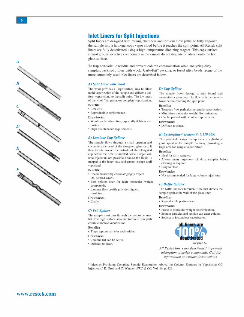
Inlet Liners for Split InjectionsSplit liners are designed with mixing chambers and tortuous flow paths, to fully vaporize the sample into a ho mo ge neous vapor cloud before it reaches the split point. All Restek split liners are fully de ac ti vat ed using a high-temperature silanizing reagent. This caps surface silanol groups so active com pounds in the sample do not degrade or adsorb onto the hot glass surface.
To trap non-volatile residue and prevent column contamination when analyzing dirty samples, pack split liners with wool, CarboFrit™ packing, or fused silica beads. Some of the more com mon ly used inlet liners are described below.
A) Split Liner with WoolThe wool provides a large surface area to allow rapid va por iza tion of the sample and deliver a uni-form vapor cloud to the split point. The low mass of the wool fiber promotes complete va por iza tion.Benefits:• Low cost.• Reproducible performance.
Drawbacks:• Wool can be adsorptive, especially if fibers are broken.• High maintenance requirements.
B) Laminar Cup SplitterThe sample flows through a small opening and en coun ters the head of the elongated glass cup. It then travels around the outside of the elongated cup before the flow is inverted twice. Larger vol-ume injections are possible because the liquid is trapped at the inner base and cannot escape until va por ized.
Benefits:• Recommended by chromatography expert Dr. Konrad Grob1.• Best splitter liner for high mo lec u lar weight compounds.• Laminar flow profile provides highest resolution.
Drawbacks:• Costly.
C) Frit SplitterThe sample must pass through the porous ceramic frit. The high surface area and tortuous flow path ensure complete vaporization.
Benefits:• Traps septum particles and residue.
Drawbacks:• Ceramic frit can be active.• Difficult to clean.
D) Cup SplitterThe sample flows through a mini funnel and en coun ters a glass cup. The flow path then inverts twice before reaching the split point.
Benefits:• Tortuous flow path aids in sample vaporization.• Minimizes molecular weight discrimination.•Can be packed with wool to trap particles.
Drawbacks:• Difficult to clean.
E) Cyclosplitter® (Patent #: 5,119,669)This patented design incorporates a cy lin dri cal glass spiral in the sample pathway, providing a large area for sample vaporization.
Benefits:• Ideal for dirty samples.• Allows many injections of dirty samples before cleaning is required. • Easy to clean.
Drawbacks:• Not recommended for large volume injections.
F) Baffle SplitterThe baffle induces turbulent flow that directs the sample against the wall of the glass liner.
Benefits:• Reproducible performance.
Drawbacks:• Prone to molecular weight discrimination.• Septum particles and residue can enter column.• Subject to incomplete vaporization.
1“Injectors Providing Com plete Sample Evap o ra tion Above the Column Entrance in Va por iz ing GC In jec tions,” K. Grob and C. Wagner, HRC & CC, Vol. 16, p. 429.
A
B
C
D
E
F
0 10 %deactivated
all liners are
See page 17.
All Restek liners are deactivated to prevent adsorption of active compounds. Call for
information on custom de ac ti va tions.

7
www.restek.com
Figure 4. Splitless injection flowpaths in a typical headpressure-regulated system.
throttling valve
carrier inlet
injection port
o-ring or ferruleinjector
liner
solenoid valve
needle valve
septum purge vent
split vent
pressure regulator
needle valve
Figure 3. Splitless injection flowpaths (injector purge off) in a typical
flow-controlled/backpressure-regulated system.
flow con trol ler
carrier gas inlet
injection port
o-ring or ferrule
injector liner
3-waysolenoid
valve
needle valve
septum purge vent
split vent
backpressure regulator
closed
Figure 3. • Solenoid valve closed between injector
and split vent: only column flow enters injector; column flow passes into column.
• Needle valve at septum purge vent allows only septum purge flow to exit septum purge vent: most of carrier gas diverted through solenoid valve, out through split vent.
• Sample vapor in injector liner can exit only to column, mixed with column flow of carrier gas.
• Solenoid valve switched to establish flowpaths as in split injection: sample vapor remaining in injection port swept out of split vent.
• Splitless hold time determined by sample composition.
to detector
analyticalcolumn
Figure 4.• Solenoid valve closed: entire carrier gas flow and entire sample directed onto analytical column.
• Carrier gas flow rate into system reduced to enable entire flow to pass through analytical column.
to detector
column
closed
Operating in the Splitless Injection ModeWhen operating in the splitless injection mode (Figures 3 and 4), the solenoid valve is switched, changing the flow path of the carrier gas. At the beginning of a splitless injection, the solenoid valve is set to prevent the flow of carrier gas from the injection port body through the solenoid valve. When the solenoid valve is in this position, only the column flow moves through the injection port liner. Column flow rate is determined by the pressure of the carrier gas in the injection port as set by the pressure regulator and the analytical column dimensions.
After a carefully determined time (the splitless hold time) the solenoid valve is switched to re-establish the flow paths as used in the split injection mode. This allows any vaporized sample remaining in the injection port to be quickly swept out of the injection port liner through the split vent. A typical splitless hold time is between 60 and 90 seconds. The ideal splitless hold time is long enough to allow most of the vaporized sample in the injection port liner to be transferred to the analytical column. Excessively long splitless hold times can produce tailing peaks and broad peaks. The splitless hold time must be determined through experimentation, and will vary according to sample composition, column length and

8
www.restek.com
ID, carrier gas flow rate, and injection port liner configuration. Table II lists approximate splitless hold times for various column IDs when operated with helium or hydrogen. The splitless hold time will decrease as either the column ID or column flow rate increases.
Setting an optimal splitless hold time also is dependent on the choice of sample solvent and the sample size. Use Table III to estimate the volume of vapor produced when using dif-ferent solvents at different pressures. The volume of vapor cloud formed should be divided by the column flow rate to determine the approximate time needed to keep the solenoid valve closed for complete sample transfer. The calculated splitless hold time also should be evaluated to provide the optimum response for the sample analytes. If the solenoid valve is
Table II. Typical splitless hold times.
ColumnFlowRate SampleTransferTime*
ColumnID HoldTime He H2 He H2
0.18mm 2 min. 0.3cc/min. 0.6cc/min. 2.7 min. 1.4 min.
0.25mm 1 min. 0.7cc/min. 1.4cc/min. 1.2 min. 0.6 min.
0.32mm 0.75 min. 1.2cc/min. 2.4cc/min. 0.7 min. 0.4 min.
0.53mm 0.5 min. 2.6cc/min. 5.2cc/min. 0.3 min. 0.2 min.
*2µL of liquid methylene chloride expanded to 0.8mL vapor at 250°C (10psig headpressure).
Table III. Solvent expansion volumes.
ExpansionVolumeinµL atvariouscolumnheadpressures
Solvent Density(g/mL) MW 5psig l0psig 15psig
Heptane 0.68 100 219 174 145
Hexane 0.66 86 245 196 163
Pentane 0.63 72 280 224 186
Toluene 0.87 92 303 242 201
Ethyl acetate 0.90 88 328 261 217
Chloroform 1.49 119 400 319 266
Methylene chloride 1.33 85 500 399 332
Methanol 0.79 32 792 629 525
H2O 1.00 18 1776 1418 1179
The expansion volumes were determined using a 1.0µL injection volume, a 250° C injection port temperature, and a headpressure of 5, 10, or 15psig (common operating pressures for 30m columns having IDs of 0.53, 0.32, or 0.25mm, respectively). For 2µL injections, double the expansion volumes.
UsetheseformulastocalculatevaluesnotlistedinTableIII:
Expansion volume = nRT / P
n = number of moles of solvent and sample. = [volume (mL) ´ density (g/mL)] / mol. wt. (g/mole)R = gas law constant = 82.06cc atm/mole °KT = absolute temperature of injector (°K) (°K = °C + 273)P = absolute column headpressure (atm) + 1 atm atm = psig ´ 0.06804 atm / psig
injector liner volume* = pr2Lp = 3.14r = liner internal radius (cm)L = liner length (cm)
*Also use this formula to determine capillary column internal volume.
VFor customer service, call800-356-1688, ext. 3
(814-353-1300, ext. 3)
or call your local Restek rep re sen ta tive.

9
www.restek.com
opened too quickly, responses will be low. However, if the solenoid valve remains closed too long, the solvent peak will tail and peak resolution will suffer. To help determine the optimal splitless hold time, a series of injections should be made using increasingly longer splitless hold times. When the response for the analytes of interest plateaus, the sample transfer process has been optimized (Figure 5).
Setting the injection port temperature for splitless injections is critical, just as it is for split injections. The injection port temperature must be high enough to completely vaporize the sample, yet not so high that it causes sample degradation. This is especially important because the residence time for a sample in the injection port during splitless injections is longer, compared to split injections.
Solvent Focusing and Analyte Focusing The long residence time for samples in the injection port also affects peak shape. In split-less injections, samples are transferred to the head of the column over a longer period of time than in split injections. As a result, initial peak bandwidths can be very broad unless vaporized samples are refocused at the head of the column. Two techniques can be used to refocus vaporized samples at the head of the column: solvent focusing and analyte focus-ing. The difference between the two methods is the initial temperature of the column oven. For solvent focusing, the initial oven temperature is low enough to allow the solvent to recondense at the head of the column. This forms a zone of liquid solvent that traps all of the vaporized sample analytes in a narrow band at the head of the column. Analyte focusing requires an initial oven temperature that allows the solvent to move through the column as a vapor immediately after injection. Analytes that have a significantly higher boiling point than the solvent are recondensed at the head of the column because of the lower oven term-perature.
A typical sequence of events for performing a splitless injection using solvent focusing is as follows:
1. Set the initial oven temperature approximately 20°C below the boiling point of the sam-ple solvent.
2. Close the solenoid valve to divert the entire sample onto the head of the column.
3. Inject the sample and hold the oven temperature at the initial temperature to recondense the solvent and focus the sample at the head of the column. The initial oven temperature is typically held for the same amount of time that the solenoid valve is closed.
4. Switch the solenoid valve to open the flow path to the split vent line and rapidly program the oven temperature (10 to 30°C/min.) until the first analyte of interest elutes.
5. Slow the oven program rate to enhance resolution of the remaining analytes of interest.
Figure 5. Optimization of splitless hold time.
The splitless hold time is optimized
when further increases do not increase analyte response but result in solvent tailing.
area
hold time (sec.)
Split and Splitless Injection in Capillary GC, 4th Ed.This comprehensive handbook of split and splitless injection techniques has been totally revised and updated, con-taining information on sample evapo-ration in the injector, matrix effects, and a new chapter on injector design. It also includes a CD-ROM contain-ing visualization of the evaporation process during split and splitless injection.
K. Grob, Wiley-VCH, 2001, 460pp., ISBN 3-527-29879-7 cat.# 20451 (ea.)

10
www.restek.com
The sequence of events for analyte focusing is the same, except for the initial oven tempera-ture; instead of starting 20°C below the boiling point of the solvent, the oven temperature is started 60–80°C below the boiling point of the earliest eluting compound.
Figure 6 shows an example of improper solvent focusing. The sample solvent is hexane, which has a boiling point of 69°C. The initial oven temperature is 150°C, or 80°C above the boiling point of hexane. The solvent peak is tailing, and the early-eluting compounds have broad peak shapes and are poorly resolved from one another. Figure 7 illustrates proper solvent focusing. The initial oven temperature, 40°C, is well below the boiling point of hexane. The square solvent peak is a good indicator of proper solvent focusing. Also notice the sharp peak shapes for both early- and late-eluting compounds. When the solvent is not detected or elicits a low response, such as hexane with electron capture detectors (ECDs), the only indication of proper solvent focusing is narrow peaks for early-eluting compounds.
For optimal solvent focusing, choose a solvent that has a boiling point at least 20°C below the boiling point of the earliest eluting target analyte. In some cases, it is not possible to select the perfect solvent to achieve focusing. For example, methylene chloride (boiling point 40°C) is frequently used for splitless work because of sample preparation techniques. Analyses performed with an initial oven temperature of 40°C will not allow the solvent to recondense at the head of the column and will not refocus the sample analytes. Ideally, ana-lysts would start the oven temperature at 20°C when using methylene chloride as the sample solvent, but because this is not practical, they must rely more on analyte focusing to refocus sample analytes at the head of the column.
An important part of solvent focusing is the ability of the solvent to “wet” the stationary phase in the column. Non-polar solvents should be used for splitless injections on non-polar stationary phases (e.g., use hexane or isooctane for injections on Rtx®-1 and Rtx®-5 col-umns). Non-polar solvents are more soluble in non-polar stationary phases and will form a more efficient zone of recondensed solvent in the column. Polar solvents are not as soluble in non-polar stationary phases and will bead up on the stationary phase rather than forming an even layer of recondensed solvent at the head of the column. Mismatches between the polarity of the solvent and the polarity of the stationary phase can cause band broadening, peak splitting, and poor resolution.
Once again, the same basic procedures are followed for analyte focusing, except the initial oven temperature is 60–80°C below the boiling point of the earliest eluting compound, instead of 20°C below the boiling point of the solvent, as with solvent focusing.
Figure 6. Initial oven temperature too high for
improper solvent focusing: solvent peak and early eluting compounds are tailing.
Figure 7. Initial oven temperature at least 20°C
below boiling point of earliest eluting analyte: early eluting compounds
are symmetrical.
30m, 0.25mm ID, 0.25µm Rtx®-5 (cat.# 10223) 1.0µL splitless in jec tion of a pesticide mix in
hexane (5ng/µL); Oventemp.:150°C to 275°C @ 4°C/min.
30m, 0.25mm ID, 0.25µm Rtx®-5 (cat.# 10223) 1.0µL splitless in jec tion of a pesticide mix in
hexane (5ng/µL); Oventemp.:40°C to 150°C @ 25°C/min. then to 275°C @ 4°C/min.
A unique situation with Agilent 5890 and 6890/6850 split/splitless inlets makes a double goose neck liner highly desirable for samples that contain compounds prone to catalytic deg-ra da tion through contact with hot metal surfac-es. Agilent splitless inlets contain a metal seal at the base of the inlet (just under the liner outlet). Because the column is installed only a few millimeters above the seal surface, the sample contacts the seal while it is being slowly drawn into the column. A double goose neck inlet liner min i miz es contact between the sample and the metal seal. A dirty seal increases the breakdown of endrin (a pesticide prone to de com po si tion) from 6% to 12.8% in an Agilent 5890 inlet when a 4mm straight inlet liner is installed. However, when a double gooseneck inlet liner is used, the breakdown remains at 2% re gard-less of whether the seal is clean or dirty. (For more information, see page 24 of this guide for a description of our Vespel® Ring Inlet Seal.)
EndrinBreakdown
LinerType CleanSeal DirtySeal
Splitless with Wool 6.0% 12.8%
Double Gooseneck 2.0% 2.4%
splitlessliner
double goose neck
liner
inlet seal
Double gooseneck inlet liner minimizes the catalytic effects of sample contact with the metal disk in an Agilent inlet.

11
www.restek.com
Inlet Liners for Splitless InjectionsThe residence time of the sample in a splitless liner is between 0.5 and 2 minutes, so splitless inlet liners do not require large surface areas for efficient vaporization (unless you are using a rapid-injecting autosampler). Splitless liners usually are designed as straight tubes. Al ter-na tive splitless liner designs, such as goose neck restrictions, help contain the sample cloud in the injector and min i mize the break down of com pounds sensitive to catalytic de com po si tion on metal inlet parts. Splitless liners should be packed with wool or fused silica beads to help with vaporization, trap non-volatile residue, and prevent column contamination when analyz-ing dirty samples. Some of the more com mon ly used splitless liners are de scribed below.
A) Straight TubeUse for samples containing a narrow molecular weight distribution and for those not prone to ther mal decomposition. Packing with wool is recommended. Wool aids in vaporization of high molecular weight com pounds and minimizes dis-crim i na tion.Benefits:• Low cost.
Drawbacks:• Potential decomposition of active compounds such as endrin and phenols when packed with wool.• Prone to high molecular weight discrimination.• Sample exposed to metal surface below liner.
B) Gooseneck
C) Recessed GooseneckBenefits:• Increases splitless efficiency.• Decreases breakdown of active compounds such as endrin and DDT.• Chamber contains sample vaporization cloud.• Can be packed with wool.
Drawbacks:• No known drawbacks.
D) Double Gooseneck
E) Recessed Double Gooseneck Best liner for catalytically labile or high mo lec-u lar weight compounds. Isolates sample from metal in jec tion port parts. Use the cyclo-version for dirty sam ples.
Benefits:• Highest splitless efficiency.• Breakdown of active compounds decreased.• Chamber contains vaporization cloud.
Drawbacks:• Higher cost than straight splitless liners.• Only recessed double goosenecks can be packed with wool.
Note: Recessed gooseneck liners offer the same ben e fits as single or double gooseneck liners, but the base of the recessed goose neck can be packed with wool and the liner can be used for dual-column anal y sis with a two-hole ferrule.
F) Drilled Uniliner® This direct injection liner features a hole drilled into the inlet end that reduces sample discrimina-tion, compared to typical splitless injections.
Benefits:• Excellent transfer of analytes to column.• Decreases injection port discrimination.• Removes excess solvent vapor.• Eliminates the need for wool.• No sample contact with metal parts below liner, less adsorption.Drawbacks:• Higher amounts of non-volatile materials transferred to column.
G) 4mm Splitless with Fused Silica WoolThe wool provides a large surface area to allow rapid va por iza tion of the sample and deliver a uni-form vapor cloud to the split point. The low mass of the wool fiber promotes complete va por iza tion.Benefits:• Low cost.• Reproducible performance.
Drawbacks:• Wool can be adsorptive, especially if fibers are broken.• High maintenance requirements.
A
B
C
D
E
F
G
0 10 %deactivated
all liners are
See page 17.
All Restek liners are deactivated to prevent adsorption of active compounds. Call for
information on custom de ac ti va tions.

12
www.restek.com
Septum Purge OptimizationThe septum purge (Figure 8) serves two func-tions: to sweep septum bleed volatiles out of the system and to reduce the potential for sample backflash contaminating the carrier gas inlet line. Optimization of the septum purge flow rate is important, especially when the inlet is operated in the splitless mode. Most GC manufacturers recommend that the septum purge flow rate be set between 3 and 5cc/min. Flow rates exceeding 5cc/min. should not be used because highly volatile sample components could be preferentially purged from the inlet liner buffer volume after vaporization. Flow rates lower than 3cc/min. can allow septum bleed to enter the inlet liner and cause ghost peaks to appear on the chromatogram.
The septum purge flow rate must be readjust-ed each time the injection pressure is changed by more than 5psig. Most GCs have a low-flow needle valve that makes septum purge adjustments easy.
Figure 8. Typical carrier gas flowpath in a
Varian split injector.
septum purge out
carrier gas in
split liner
column
spring
split point
split vent out
ferrule
GC_EX00600
Rtx®-5 15m, 0.32mm ID, 1.50µm (cat.# 10266)Sample: 50µg/mL PAH standard (cat.#31011 ) in hexaneInj.: 1.0µL splitless (hold 2 min.), 4mm single gooseneck inlet liner w/FSwool (cat.# 22405)Inj. temp.: 200°CCarrier gas: helium, constant pressureLinear velocity: 76cm/sec. @ 40°COven temp.: 40°C(hold 4min.) to 325°C @10°C/min. (hold 5 min.)Det.: FID @350°C
Figure 9. Injector temperature affects the recovery of higher molecular weight compounds.
GC_EX00601
1. naphthalene 2. acenaphthylene 3. acenaphthene 4. fluorene 5. phenanthrene 6. anthracene 7. fluoranthene 8. pyrene 9. benzo(a)anthracene 10. chrysene 11. benzo(b)fluoranthene 12. benzo(k)fluoranthene 13. benzo(a)pyrene 14. indeno(1,2,3-cd)pyrene 15. dibenzo(a,h)anthracene 16. benzo(ghi)perylene
Injector temp: 300°CInjector temp: 200°C

13
www.restek.com
Problems Associated with Split and Splitless InjectionsWhen performed properly, split and splitless injections are easy to automate, produce nar-row peaks, and yield consistent run-to-run peak areas. However, split and splitless injections have inherent limitations associated with vaporizing the sample in a hot injection port.
Thermal Decomposition: The injection port temperature is a critical factor in optimiz-ing hot vaporization injection techniques. If the injection port temperature is too low, high molecular weight analytes will not vaporize completely and will not be transferred to the head of the column efficiently (as shown by peaks 14, 15 and 16 in Figure 9). If the injec-tion port temperature is too high, thermally labile compounds can break down inside the injection port before reaching the column. Figure 10 shows the effect of temperature on thermally labile TMS derivatives of fatty acids. When the injection port temperature is set at 280°C, the response for the TMS derivatives is reduced. When the injection port tempera-ture is lowered to 200°C, the response for the TMS derivatives is comparable to triacontane at equivalent sample concentrations. Careful optimization of injection port temperatures will maximize sample vaporization while minimizing sample decomposition.
Active Compounds: Active compounds can be problematic in split or splitless injections. The high surface area and heat needed to uniformly vaporize the sample can cause these compounds to break down or be adsorbed onto the surface of the injection port liner. Deactivated inlet liners, and Silcosteel®-treated or gold-plated inlet seals can help minimize active sites in the injection port. If tailing peaks and poor response for active compounds cannot be corrected by using properly deactivated inlet liners and treated inlet seals, other injection techniques such as cold on-column or temperature-programmed injections should be considered.
Molecular Weight Discrimination: In hot vaporization injections, one injection port tem-perature is used to vaporize all of the analytes in one sample injection. Compounds span-ning a range of molecular weights and boiling points will exhibit differences in response for equal concentrations of analyte. High molecular weight, high boiling point analytes will have a noticeably reduced response when compared to lower molecular weight, lower boiling point analytes. This effect is more pronounced when analyzing samples that have a broad range of molecular weights and boiling points. Samples containing analytes that are more closely grouped by molecular weight and boiling point show less molecular weight discrimination.
1. TMS tetracosanoate (thermolabile) 2. n-triacontane (stable) 3. TMS hexacosanoate (thermolabile)
15m x 0.32mm ID fused silica coated with 0.25µm bonded methyl siliconeSample: 1µL each of TMS n-tetracosanoate, TMS n-hexacosanoate, and n-triacontane in n-nonane at 2ng/µL each component.
GC: 3000 Series Varian gas chromatograph with 1077 split/splitless injector, FID and autos-ampler. Split/splitless injector: Run 1: SPI held at 280° C Run 2: SPI held at 200°CCarrier gas: helium at 47cm/sec.Oven: 130° to 280°C 20°C/min. (hold 2 min.)FID: 300°C, 32 x 10-12
1
2
3
1 23
Chromatograms courtesy of VarianInstrument Co.
280°C: Injector too hot, thermal degradation evident
200°C: Injector tempera-ture appropriate, break-
down minimized
Figure 10. The Donike Test illustrates the importance of injector temperature when a sample
contains thermally labile compounds.
VFor customer service, call
800-356-1688, ext. 3(814-353-1300, ext. 3)
or call your local Restek rep re sen ta tive.

14
www.restek.com
Figure 11 demonstrates the molecular weight discrimination experienced when analyz-ing a series of hydrocarbons with a broad range of molecular weights (C6 through C44). Alternative injection techniques, such as cold on-column injection, can be used to minimize molecular weight discrimination.
Molecular weight discrimination is usually very repeatable. In split and splitless injections, if the same injection port temperature, carrier gas pressure, sample size and sample solvent are used for every injection, sample vaporization should be a reproducible process. Any molecular weight discrimination experienced should be the same from one injection to the next. Because of this consistency, many analysts choose to ignore molecular weight dis-crimination unless it compromises overall sensitivity. To help compensate for differences in response due to molecular weight discrimination, multiple internal standards can be used to mimic the range of molecular weights and boiling points for the analytes in the sample.
Molecular weight discrimination can be minimized by choosing an injection port liner that ensures the sample is completely and uniformly vaporized. Inadequate vaporization causes the sample to approach the head of the column in both the aerosol and vapor states. Aerosol droplets, consisting predominantly of high molecular weight compounds, can be driven past the head of the column by the momentum of the carrier gas and will be preferentially swept out of the injection port and through the split vent. Injection port liners that are packed with glass wool or that incorporate a flow diverting device within their bore assist in vaporizing the sample and transferring a homogeneous representation to the head of the column.
Needle Discrimination: During sample injections, the syringe needle undergoes some degree of heating in the injection port. The temperature reached by the needle can influ-ence the relative response for low and high molecular weight analytes. During the process of expelling the sample from the syringe, the contents in the needle are not completely transferred to the injection port. As the needle begins to heat, low molecular weight analytes begin to vaporize from the needle while higher molecular weight analytes remain inside the needle. Therefore, the lower molecular weight analytes will show enhanced response compared to higher weight analytes (Figure 12). Three techniques can be used to minimize needle discrimination in split and splitless injections.
The first technique is to inject the sample as rapidly as possible. Rapid injections minimize the amount of time the needle spends in the injection port and reduces the amount of heat-ing the needle experiences. When making rapid injections in straight injection port liners for split or splitless analysis, the sample can be propelled beyond the inlet of the column and onto the injector base fitting. Always pack injection port liners with deactivated glass wool or CarboFrit™ packing, or use a flow diverting device like a laminar cup to assist in sample
Figure 11.Splitter discrimination typical of split and splitless injections.
Splitter discrimination is evident from relatively enhanced peak heights for the early-eluting com-pounds and diminished peak heights for the later-eluting higher molecular weight compounds. The same sample analyzed by cold on-column injection shows no discrimination; the peak heights for low and high molecular weight compounds are truly representative of this sample.
Discrimination typical of a split or splitless injector. Injector temperature: 340°C
Cold on-column injection provides accurate information. Injector temperature: 40°C.
30m, 0.32mm ID, 0.25µm Rtx®-1 (cat.# 10124)Inj. volume: 0.2µLOn-column conc.: 15ng. Oven temp.: 40°C to 340°C @ 5°C/min.
Det. (FID) temp.: 340°CLinear velocity: 50cm/sec., hydrogen Attenuation: 8x10-11AFS
4 12 20 28 36 44 52min. 4 12 20 28 36 44 52min.
septum
vaporizing chamber
syringe
volatile solutes(vapor state)
high boiling materials (aero-
sols)
residual layer of high-boiling point materials
evaporating solvent and
volatile solutes
sample liquid
columninlet
needle
Figure 12.Factors in discrimination: high molecular
weight material clinging to the syringe needle and non-ho mo ge neous vapor-ization of the sample in the inlet liner.
C6
C44
C6C44

15
www.restek.com
vaporization. Figure 13 shows the improvement in peak shape when an HP autosampler is used with an injection port liner packed with wool, versus a liner without wool.
The second technique is to use hot needle injection. Hot needle injections are performed by drawing the sample all the way into the syringe barrel, leaving the needle empty. When the needle is introduced into the injection port the injection in delayed for a short period of time (3–5 seconds, for example) to allow the needle to heat completely. Then the syringe plunger is depressed and the sample is expelled into the injection port liner.
The third technique is to use a solvent flush with each injection. This technique involves drawing a small amount of solvent into the syringe, followed by a small amount of air, fol-lowed by the desired amount of sample. All of the solvent, air, and sample are then drawn into the barrel of the syringe, just as in a hot needle injection. The needle is preheated, as in the hot needle injection, and the contents of the syringe are expelled into the injection port liner. The solvent that was first drawn into the syringe acts to flush the syringe barrel and needle, and completely transfers all of the sample during the injection process.
Backflash: Backflash occurs when the volume of the vaporized sample exceeds the volume inside the injection port liner. Most of the excess vaporized sample escapes out the top of the injection port liner. Some of it is swept down the septum purge line. Another portion of it can back up into the carrier gas supply line, and some of it can be re-introduced into the injection port. Backflash can cause poor peak area reproducibility, tailing peaks, split peaks, and poor resolution.
Table III (page 8) shows the estimated expansion volumes for 1µL injections of a variety of solvents. When using an injection port temperature of 250°C and a carrier gas pressure of 10psig, most solvents will vaporize and expand to a volume that exceeds the capacity of a 2mm ID injection port liner (approximately 240µL, see Table IV). In order to minimize backflash, injection port parameters must be carefully optimized. Injection port temperature, carrier gas pressure, sample size, and rate of injection all should be adjusted to ensure the vaporized sample remains inside the liner prior to being transferred to the head of the col-umn.
Sample Size and Injection Port Temperature:As the equation in Table III shows, the volume of vaporized sample produced is directly related to the size of the liquid sample (n) and the temperature of the injection port (T). A decrease in either of these values will translate into a smaller vaporized sample volume. If the injection port temperature cannot be decreased because of vaporization problems and the sample size cannot be decreased because of sensitivity issues, backflash must be minimized by optimizing the rate of injec-tion or by adjusting the carrier gas pressure.
Figure 13. Always pack splitless inlet liners with wool when using rapid injection autosamplers.
4mm ID splitless liner without wool may exhibit fronting peaks.
4mm ID splitless liner with wool eliminates fronting peaks by promoting
sample vaporization.
20 24 28 32 36 20 24 28 32 36
Table IV. Liner Volumes.
Theoretical* Effective
1.0mm ID = 59µL 30µL
2.0mm ID = 236µL 118µL
3.0mm ID = 530µL 265µL
4.0mm ID = 942µL 471µL
*Liner volume actually available for vaporization with carrier gas present is ´ 1/2 theoretical, due to the presence of carrier gas in the liner.
From Split and Splitless Injection in Capillary GC, 3rd Ed., K. Grob, Wiley-VCH, 2001.

Optimizing the Rate of Injection: Figure 14 shows the effect of varying rates of injection for a 5µL sample. When a rapid injection (5µL/sec.) is made, the solvent peak tails and the responses for equal concentrations of each analyte are not reproducible. A 1µL/sec. injection rate improves the solvent peak shape, but the response for each analyte still is not propor-tional to the concentration of each analyte. Only when the injection rate is slowed to 0.2µL/sec. does the response for each analyte become consistent with the amount injected.
Some autosamplers are capable of slowing the injection rate to minimize backflash, but most autosamplers use a rapid injection sequence. If large-volume injections must be made rapidly, adjustments to the carrier gas pressure must be used to control sample expansion.
Pressure Programming: Pressure (P) is in the denominator of the equation in Table III (page 8). Any increase in carrier gas pressure will help to reduce sample expansion volume. Most of the latest models of GCs incorporate electronic pressure control (EPC) of the carrier gas pressure. Pressure can be time-programmed so that the carrier gas pressure initially is very high, then is reduced after the injection to optimize carrier gas flow rate for best resolu-tion. Setting the initial carrier gas pressure to a high value will reduce the amount of sample expansion that occurs at the point of injection and will speed up the transfer of the vapor-ized sample from the liner to the head of the column.
Direct Injection as an Alternative to Splitless InjectionDirect injections are an alternative approach for injecting samples with low concentrations of analytes. Direct injections vaporize the entire sample in a heated injection port, just like split and splitless injections. However, in direct injections, there is only one flow path through the injection port. All of the carrier gas is directed into the column and, hence, the entire vaporized sample is directed into the column as well. This can be accomplished by using a specially designed injection port liner. Unliner® injection port liners have an internal taper in one end that allows a direct connec-tion between the liner and the capillary col-umn. With this connection, the flow path from the injection port body through the split vent is blocked and all of the carrier gas flow is directed into the capillary column. Figure 15 illustrates how a Uniliner® injection port liner with a Press-Tight® seal forms a leak-free connection between the liner and the column.
16
www.restek.com
5µL/sec.injectionrate
1µL/sec.injectionrate
0.2µL/sec.injectionrate
Figure 14. The injection rate must be slower for large volume splitless injections.
Solvent: Isooctane 1. n-C122. n-C143. n-C164. n-C185. n-C20
5µLinjection
Chromatograms courtesy of Varian Instrument Co.
Figure 15. A Uniliner® liner forms a leak-tight seal with the column, preventing the sample from contacting metal parts at the base
of a splitless injection port.
inlet seal
splitless liner
Uniliner®
with aPress-Tight®
seal
12 3 4 5
VFor customer service, call
800-356-1688, ext. 3(814-353-1300, ext. 3)
or call your local Restek rep re sen ta tive.
17
www.restek.com
17
VFor customer service, call
800-356-1688, ext. 3(814-353-1300, ext. 3)
or call your local Restek rep re sen ta tive.
Because all of the carrier gas flow and the entire vaporized sample is directed into the capil-lary column, direct injections give comparable performance to splitless injections. Faster carrier gas flow rates usually are used to speed up the sample transfer process, and improve peak shapes and resolution. Direct injections can be used as another option to minimize molecular weight discrimination and loss of active compounds.
A Uniliner® inlet liner can be used as a direct replacement for a splitless liner. It can be installed in the same manner as a splitless liner, except that the system must be operated continuously with the solenoid valve closed. Uniliner® inlet liners are designed to accommodate 0.32 or 0.53mm ID columns. Request Restek’s Guide to Direct On-Column Vaporization Injection (lit. cat.# 59882) for more information on how to perform and optimize direct injections.
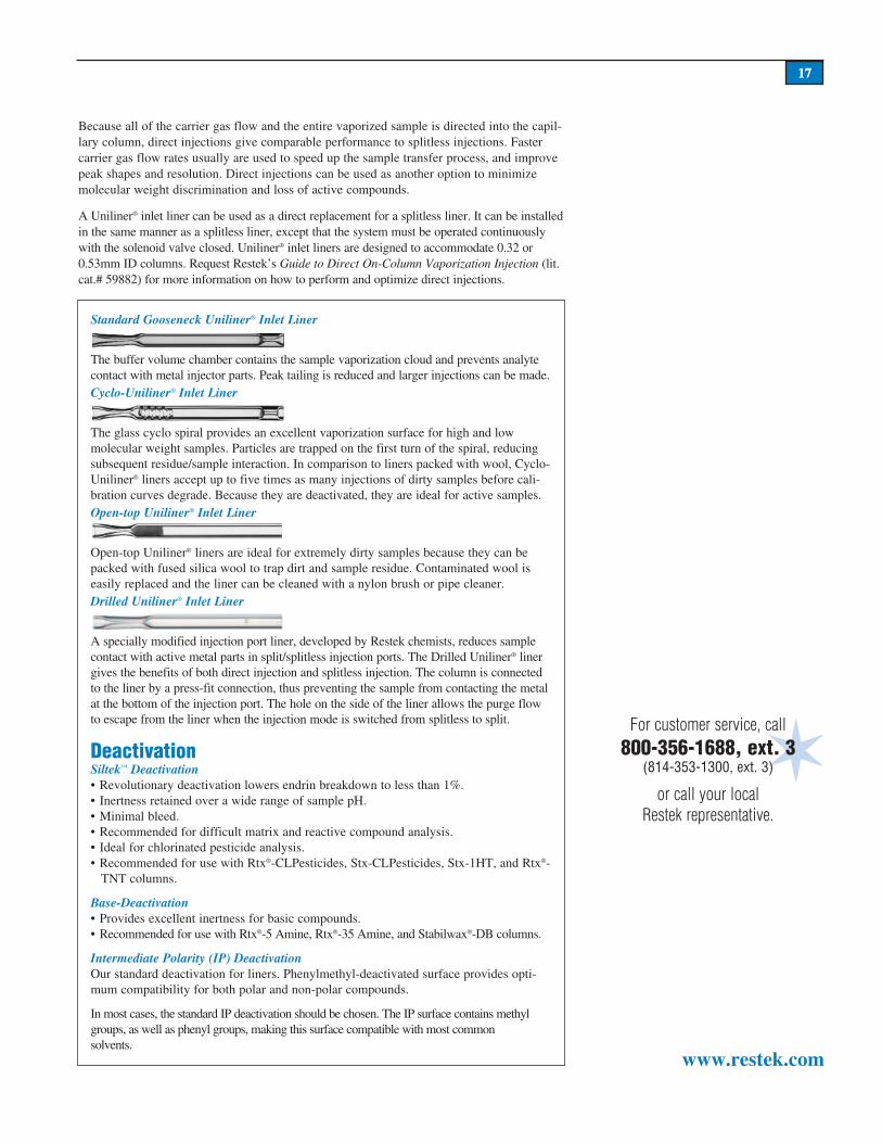
Standard Gooseneck Uniliner® Inlet Liner
The buffer volume chamber contains the sample va por iza tion cloud and prevents analyte contact with metal injector parts. Peak tailing is reduced and larger injections can be made. Cyclo-Uniliner® Inlet Liner
The glass cyclo spiral provides an excellent vaporization surface for high and low molecular weight samples. Particles are trapped on the first turn of the spiral, reducing subsequent residue/sample interaction. In com par i son to liners packed with wool, Cyclo-Uniliner® liners accept up to five times as many injections of dirty samples before cal i-bra tion curves degrade. Because they are deactivated, they are ideal for active samples.Open-top Uniliner® Inlet Liner
Open-top Uniliner® liners are ideal for extremely dirty samples because they can be packed with fused silica wool to trap dirt and sample residue. Contaminated wool is easily replaced and the liner can be cleaned with a nylon brush or pipe cleaner.Drilled Uniliner® Inlet Liner
A specially modified injection port liner, developed by Restek chemists, reduces sample contact with active metal parts in split/splitless injection ports. The Drilled Uniliner® liner gives the benefits of both direct injection and splitless injection. The column is connected to the liner by a press-fit connection, thus preventing the sample from contacting the metal at the bottom of the injection port. The hole on the side of the liner allows the purge flow to escape from the liner when the injection mode is switched from splitless to split.
DeactivationSiltek™ Deactivation• Revolutionary deactivation lowers endrin breakdown to less than 1%.• Inertness retained over a wide range of sample pH.• Minimal bleed.• Recommended for difficult matrix and reactive compound analysis.• Ideal for chlorinated pesticide analysis.• Recommended for use with Rtx®-CLPesticides, Stx-CLPesticides, Stx-1HT, and Rtx®-
TNT columns.
Base-Deactivation• Provides excellent inertness for basic compounds.• Recommended for use with Rtx®-5 Amine, Rtx®-35 Amine, and Stabilwax®-DB columns.
Intermediate Polarity (IP) DeactivationOur standard deactivation for liners. Phenylmethyl-deactivated surface provides opti-mum compatibility for both polar and non-polar compounds.
In most cases, the standard IP deactivation should be chosen. The IP surface contains methyl groups, as well as phenyl groups, making this surface compatible with most common solvents.

18
www.restek.com
Hints for Analyzing Dirty SamplesWhen injecting dirty samples, non-volatile contaminants such as high molecular weight compounds, septum particles, derivatization reagents, salts, and pyrolyzed samples adhere to the interior wall of the injection port liner after the sample solvent and sample analytes have been vaporized. As this layer of residue thickens, it can cause loss of response for active compounds. Figure 16 illustrates this effect when highly active phenols are analyzed on a clean and a dirty inlet liner. In this example, responses are reduced because of adsorptive effects in the liner.
Non-volatile contamination can be trapped in the injection port liner by using a small plug of deactivated fused silica or glass wool. Usually a 1cm plug of wool, positioned in the center of the injection port liner, is sufficient to provide a surface for non-volatile contami-nation to collect. Some instrument manufacturers provide specific instructions on packing injection port liners to maximize quantitative accuracy and minimize discrimination. If fused silica wool or glass wool is used in an injection port liner, it should be replaced as part of the routine maintenance schedule for the injection port. Regular replacement of the wool in the injection port liner will extend the lifetime of the injection port liner as well as prevent chromatographic problems from extensive non-volatile contaminant build up. When replacing the wool during routine maintenance, minimize handling of the wool by using a wool puller tool (cat.# 20114).
If fused silica or glass wool is not an effective mode of trapping non-volatile contamination under your conditions, injection port liners with a “cyclo” or glass frit design can be used to trap non-volatile contamination. While these types of injection port liners may provide effective trapping of non-volatile contamination, they are harder to clean than straight injec-tion port liners packed with wool.
In the past, some instruments were supplied with injection port liners that were packed with a small amount of packed column packing material. We do not recommend using this type of injection port liner. Diatomites used in packed column GC packings often are active and contain impurities that increase adsorptive effects for active compounds. Also, the stationary phases that are used in these packings can produce significant bleed when used in injection ports at elevated temperatures.
Guard ColumnsGuardcolumnsprotectanalytical
columnsinseveralways:
Guard columns trap non- vol a tile res i-dues, preventing them from col lect ing at the analytical column inlet. These residues may be very high molecular weight organic com pounds, inorganic salts, or particles. If these con tam i nants enter the analytical column, they can cause ad sorp tion of ac tive com pounds, loss of resolution, and poor peak sym-metry. When this con tam i na tion be gins to affect sample analysis, a small sec-tion of the analytical col umn must be re moved to restore proper per for mance. Each time a column section is re moved, re ten tion times change, and some res o-lu tion is lost. By using a guard col umn and removing con tam i nat ed loops from it in stead of from the an a lyt i cal col umn, analytical col umn length and in ert ness remain in tact.
Guard columns also allow more in jec-tions to be made before con tam i na-tion in ter feres with an a lyt i cal results. Because there is no stationary phase coated on a guard col umn, the amount of time the sam ple spends in the guard column is minimal. This re duc es the interaction be tween sam ple com po nents and con tam i na tion from non-volatile residue in the guard col umn.
For more information on selecting a guard column for your analysis, request our Fast Facts GC Capillary Column Guard Col umns (lit. cat.# 59319).
Figure 16.Phenols are adsorbed after several injections of a dirty sample.
1. phenol 2. 2-chlorophenol 3. 2-nitrophenol 4. 2,4-dimethylphenol 5. 2,4-dichlorophenol 6. 4-chloro-3-methylphenol 7. 2,4,6-trichlorophenol 8. 2,4-dinitrophenol 9. 4-nitrophenol 10. 2-methyl-4,6-dinitrophenol 11. pentachlorophenol
Initially, phenols respond well on a clean, deactivated inlet liner. However, after several injections of Southern Louisiana crude oil, responses are greatly di min ished due to the sample’s interaction with non-volatile residue in the inlet liner.
1
2
3
4
6
5
87
9
11
10
min. 4 8 12 16
15m, 0.32mm ID, 1.0µm Rtx®-5 (cat.# 10251)0.2µL split injection of phenols (604 Phenol Mix, cat.# 31029)Oventemp.: 80°C to 290°C @ 8°C/min.lnj.&det:temp.: 310°CCarriergas: hydrogen Linearvelocity: 45cm/sec.FIDsens.: 16x10-11
Splitratio: 9:1
1
2
3
4
6
5
8
79
1110
min. 4 8 12 16
Mini Wool Puller/InserterMakes inserting and removing wool easy. Not recommended for double gooseneck liners.
Description qty. cat.#Mini Wool Puller/Inserter 2-pk. 20114

19
www.restek.com
In addition to using a clean and deactivated injection port liner, we recommend using a five-meter deactivated guard column when analyzing dirty samples. Routine maintenance of the liner and the guard column will prevent dirty samples from contaminating the analytical column, and will help ensure reproducible and accurate analytical results.
Hints for Performing Routine Injection Port MaintenanceInjection port maintenance should be performed prior to installing any capillary column. Maintenance of the injection port after a column is installed should be performed periodical-ly, based on the number of injections made and the cleanliness of the samples. Maintenance includes cleaning, deactivating, or replacing injection port liners, and replacing critical inlet seals and the septum. Review the instrument manual inlet diagram prior to disassembling the inlet.
Cleaning and Deactivating Injector Liners For optimum column performance, the injection port liner must be free of septum particles, sample residue, and ferrule fragments. Use a deactivated injection port liner when analyz-ing samples with compounds that are active or prone to decomposition or adsorption on untreated glass surfaces. Table V illustrates the importance of a deactivated injection port liner when analyzing active compounds. The response factors (RF) for all three of these active compounds were much lower with non-deactivated inlet liners.
If the injection port liner is deactivated and is not excessively dirty, cleaning with organic solvents usually is enough to restore original performance. Most organic solvents will not affect the integrity of the surface deactivation. First, remove septum particles that adhere to the inside wall of the injection port liner by rinsing with methanol or isopropanol. Next, use pentane, methylene chloride or toluene to remove sample residue. Do not use laboratory detergents, acids, or bases to clean injection port liners. Harsh cleaning agents will remove or damage the deactivation layer and the liner will require re-deactivation. Nylon brushes and pipe cleaners (cat.# 20108) can be used for mild abrasive cleaning of injection port liners.
Replacing Critical SealsReplace critical seals prior to installing an injection port liner (see the instrument manual for seal locations). In most capillary injection ports, an o-ring or ferrule made of rubber or graphite is used to seal the injection port liner into the injection port body. It is critical that the seal fits tightly around the liner, to prevent the carrier gas from leaking around the out-side of the liner. Check for leaks with a thermal conductivity-type leak detector (e.g., Leak Detective™ II, cat.# 20413).
Changing SeptaAlways use a high-quality, low-bleed septum. We recommend replacing the septum fre-quently, to prevent leaks and fragmentation. Multiple injections and continuous exposure to hot injection port surfaces will decompose the septum and cause particles to fall into the injection port liner. Septum particles are a potential source of ghost peaks, loss of inertness, and carrier gas flow occlusion. It is best to install a new septum at the end of an analytical sequence so that it can condition in the injector and reduce the incidence of ghost peaks. To avoid contamination, always use forceps when handling septa. Restek’s high quality, low-bleed Thermolite® septa are available for most common models of capillary GCs. For more information, request a copy of Restek’s Guide to Minimizing Septa Problems (lit. cat.# 59886).
Compound RFDeactivatedLiner RFUndeactivatedLiner
2,4-dinitrophenol 0.248 0.185
pentachlorophenol 0.240 0.188
benzidine 0.327 0.234
Table V.Deactivated inlet liners show higher response factors for active components.
RF relative to naphthalene;
N=3
For additional hints for analyzing dirty samples, request a copy of Restek’s A Guide When Injecting Dirty Samples (lit. cat.# 59881).
Nylon Tube Brushes and Pipe CleanerUse to remove small septum fragments and residue from dirty glass inlet liners. Brushes are 1/8-, 3/16-, and 1/4-inch in diam-eter; pipe cleaner is one foot long.
Leak Detective™ II Leak Detector• Affordable thermal conductivity leak
detector—every analyst can have one.*• Compact, ergonomic design is easy to
hold and operate with one hand.• Helium, hydrogen, and nitrogen can
be detected at 1x10⁻⁴cc/sec. or at an absolute concentration as low as 100ppm.**
• Fast results—responds in less than 2 seconds to trace leaks of gases with thermal conductivities different than air.
• Micro-chip design improves sensitivity and response time over previous models.
• Auto zeroing with the touch of a button. • Battery-operated for increased porta-
bility (one 9-volt).
Description qty. cat.#
Leak Detective™ II Leak Detector (9 volt, Battery-Operated) ea. 20413
Description qty. cat.#
Nylon Tube Brushes and Pipe Cleaner set 20108
*Never use liquid leak detectors on a capillary sys-tem because liquids can be drawn into the column.**Caution: NOT designed for determining leaks of combustible gases. A combustible gas detector should be used for determining combustible gas leaks in possibly hazardous conditions.

20
www.restek.com
20
Base-Deactivated Inlet Liners for Agilent GCsIf you do not see the deactivated liner you need, you can order it on a custom basis by adding the appropriate suffix number to the liner catalog number. For base deactivation: each (-210.1), 5-pack (-210.5), 25-pack (-210.25). For base-deactivated liners packed with base-deactivated wool: each (-211.1), 5-pack (-211.5), 25-pack (-211.25).
Prepacked LinersLet Restek do the work! Just add the appropriate suffix to the liner catalog number.
Siltek™ Deactivation—The Next Generation• Maximizes the inertness of the sample pathway.• Minimizes breakdown.• Low bleed.• Thermally stable.• “Clean and green”—manufactured without the use of harmful organic solvents.
Restek offers the next generation of deactivation. The Siltek™ deactivation process (patent pending) produces a highly-inert glass surface, which features high temperature stability, extreme durability, and low bleed. Try Siltek™ liners, guard columns, wool, and connectors for better recovery of sample analytes.
For Siltek™ inlet liners, add the corresponding suffix number to your liner catalog number.
ea. 5-pk. 25-pk.4mm Split Straight w/ Wool
20781-211.1 20782-211.5 20783-211.25Cyclosplitter®
20706-210.1 20707-210.5 —4mm Splitless Straight
20772-210.1 20773-210.5 20774-210.252mm Gooseneck
20795-210.1 20796-210.5 20797-210.254mm Gooseneck
20798-210.1 20799-210.5 20800-210.25
Prepacked Inlet Liners Suffix Numbersqty. FS Wool FS Beads Glass Wool CarboFrit™†ea. -200.1 -201.1 -202.1 -209.1
5-pk. -200.5 -201.5 -202.5 -209.525-pk. -200.25 -201.25 -202.25 -209.25
Siltek™ with Siltek™ withqty. Siltek™ Siltek™ wool CarboFrit™
each -214.1 addl. cost -213.1 addl. cost -216.1 addl. cost5-pk. -214.5 addl. cost -213.5 addl. cost -216.5 addl. cost25-pk. -214.25 addl. cost -213.25 addl. cost -216.25 addl. cost
VFor customer service, call
800-356-1688, ext. 3(814-353-1300, ext. 3)
or call your local Restek rep re sen ta tive.
featuring
Siltek™deactivation
†CarboFrit™ inserts require a neck greater than 2mm.
Deactivation—Which Should You Choose?Siltek™ Deactivation• Revolutionary deactivation lowers
endrin breakdown to less than 1%.• Inertness retained over a wide range
of sample pH.• Minimal bleed.• Recommended for difficult matrix
and reactive compound analysis.• Ideal for chlorinated pesticide analysis.• Recommended for use with Rtx®-
CLPesticides, Stx-CLPesticides, Stx-1HT, and Rtx®-TNT columns.
Base-Deactivation• Provides excellent inertness for basic
compounds.• Recommended for use with Rtx®-
5 Amine, Rtx®-35 Amine, and Stabilwax®-DB columns.
21
www.restek.com
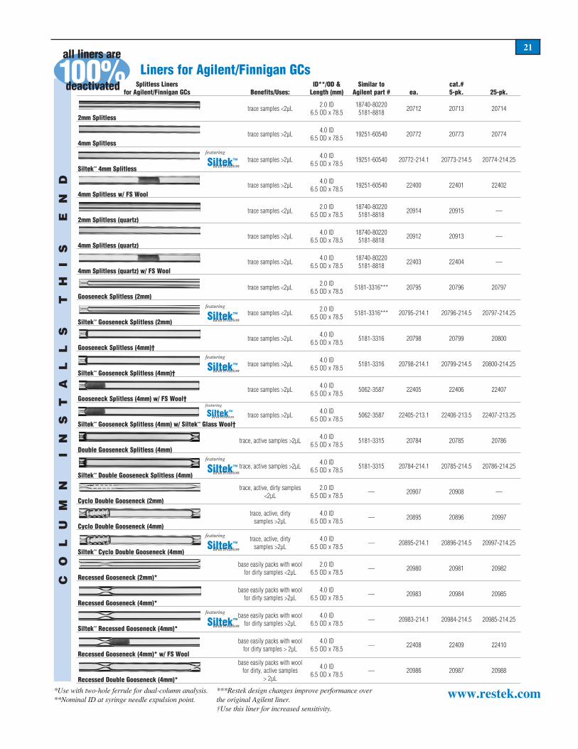
Splitless Linersfor Agilent/Finnigan GCs Benefits/Uses:
ID**/OD &Length (mm)
Similar to Agilent part # ea.
cat.#5-pk. 25-pk.
2mm Splitlesstrace samples <2µL 2.0 ID
6.5 OD x 78.518740-802205181-8818 20712 20713 20714
4mm Splitlesstrace samples >2µL 4.0 ID
6.5 OD x 78.5 19251-60540 20772 20773 20774
Siltek™ 4mm Splitlesstrace samples >2µL 4.0 ID
6.5 OD x 78.5 19251-60540 20772-214.1 20773-214.5 20774-214.25
4mm Splitless w/ FS Wooltrace samples >2µL 4.0 ID
6.5 OD x 78.5 19251-60540 22400 22401 22402
2mm Splitless (quartz)trace samples <2µL 2.0 ID
6.5 OD x 78.518740-802205181-8818 20914 20915 —
4mm Splitless (quartz)trace samples >2µL 4.0 ID
6.5 OD x 78.518740-802205181-8818 20912 20913 —
4mm Splitless (quartz) w/ FS Wooltrace samples >2µL 4.0 ID
6.5 OD x 78.518740-802205181-8818 22403 22404 —
Gooseneck Splitless (2mm)trace samples <2µL 2.0 ID
6.5 OD x 78.5 5181-3316*** 20795 20796 20797
Siltek™ Gooseneck Splitless (2mm)trace samples <2µL 2.0 ID
6.5 OD x 78.5 5181-3316*** 20795-214.1 20796-214.5 20797-214.25
Gooseneck Splitless (4mm)†trace samples >2µL 4.0 ID
6.5 OD x 78.5 5181-3316 20798 20799 20800
Siltek™ Gooseneck Splitless (4mm)†trace samples >2µL 4.0 ID
6.5 OD x 78.5 5181-3316 20798-214.1 20799-214.5 20800-214.25
Gooseneck Splitless (4mm) w/ FS Wool†trace samples >2µL 4.0 ID
6.5 OD x 78.5 5062-3587 22405 22406 22407
Siltek™ Gooseneck Splitless (4mm) w/ Siltek™ Glass Wool†trace samples >2µL 4.0 ID
6.5 OD x 78.5 5062-3587 22405-213.1 22406-213.5 22407-213.25
Double Gooseneck Splitless (4mm)trace, active samples >2µL 4.0 ID
6.5 OD x 78.5 5181-3315 20784 20785 20786
Siltek™ Double Gooseneck Splitless (4mm)trace, active samples >2µL 4.0 ID
6.5 OD x 78.5 5181-3315 20784-214.1 20785-214.5 20786-214.25
Cyclo Double Gooseneck (2mm)
trace, active, dirty samples <2µL
2.0 ID6.5 OD x 78.5 — 20907 20908 —
Cyclo Double Gooseneck (4mm)
trace, active, dirty samples >2µL
4.0 ID6.5 OD x 78.5 — 20895 20896 20997
Siltek™ Cyclo Double Gooseneck (4mm)
trace, active, dirty samples >2µL
4.0 ID6.5 OD x 78.5 — 20895-214.1 20896-214.5 20997-214.25
Recessed Gooseneck (2mm)*
base easily packs with wool for dirty samples <2µL
2.0 ID6.5 OD x 78.5 — 20980 20981 20982
Recessed Gooseneck (4mm)*
base easily packs with wool for dirty samples >2µL
4.0 ID6.5 OD x 78.5 — 20983 20984 20985
Siltek™ Recessed Gooseneck (4mm)*
base easily packs with wool for dirty samples >2µL
4.0 ID6.5 OD x 78.5 — 20983-214.1 20984-214.5 20985-214.25
Recessed Gooseneck (4mm)* w/ FS Wool
base easily packs with woolfor dirty samples > 2µL
4.0 ID6.5 OD x 78.5 — 22408 22409 22410
Recessed Double Gooseneck (4mm)*
base easily packs with wool for dirty, active samples
> 2µL
4.0 ID6.5 OD x 78.5 — 20986 20987 20988
CO
LU
MN
I
NS
TA
LL
S
TH
IS
E
ND
featuring
Siltek™deactivation
featuring
Siltek™deactivation
featuring
Siltek™deactivation
featuring
Siltek™deactivation
featuring
Siltek™deactivation
featuring
Siltek™deactivation
featuring
Siltek™deactivation
*Use with two-hole ferrule for dual-column analysis.**Nominal ID at syringe needle expulsion point.
***Restek design changes improve performance over the original Agilent liner.†Use this liner for increased sensitivity.
0 10 %deactivated
all liners areLiners for Agilent/Finnigan GCs

22
www.restek.com
Split/Splitless Liners forAgilent 6890 GCs Benefits/Uses
ID**/OD &Length (mm)
Similar toAgilent part #
cat.#ea.
Low Pressure Drop Liner w/ Wool
universal, use with Agilent 6890 GCs
4.0 ID6.3 OD x 78.5 5183-4647 21032 21033
Split Linersfor Agilent/Finnigan GCs Benefits/Uses:
ID**/OD &Length (mm)
Similar toAgilent part# ea.
cat.#5-pk. 25-pk.
1mm Split†
for purge & trap inlet splitting
or sample <1µL
1.0 ID6.3 OD x 78.5 — 20972 20973 —
4mm Split with Wool*
universal, use with Agilent 7673 autosampler
4.0 ID6.3 OD x 78.5 19251-60540 20781 20782 20783
Siltek™ 4mm Split w/ Siltek™ Glass Wool
universal, use with Agilent 7673 autosampler
4.0 ID6.3 OD x 78.5 19251-60540 20781-213.1 20782-213.5 20783-213.25
Laminar Cup Splitterhigh MW compounds 4.0 ID
6.3 OD x 78.5 18740-80190 20801 20802 —
mini-Lam™ Splithigh MW compounds 4.0 ID
6.3 OD x 78.5 — 20990 20991 —
Cup Splitter
high & low MW compounds
4.0 ID6.3 OD x 78.5 18740-80190 20709 20710 —
Siltek™ Cup Splitter
high & low MW compounds
4.0 ID6.3 OD x 78.5 18740-80190 20709-214.1 20710-214.5 —
Cyclosplitter®
dirty samples, many injections before cleaning required
4.0 ID6.3 OD x 78.5 — 20706 20707 20708
4mm Split Precision Liner
dirty samples, trace samples
4.0 ID6.3 OD x 78.5 — 21022 21023 20979
Siltek™ 4mm Split Precision Liner w/ Siltek™ Glass Wool
dirty samples, trace samples
4.0 ID6.3 OD x 78.5 — 21022-213.1 21023-213.5 20979-213.25
*Use with two-hole ferrule for dual-column analysis.**Nominal ID at syringe needle expulsion point.
***Restek design changes improve performance over the original Agilent liner.†Use this liner for increased sensitivity.
CO
LU
MN
I
NS
TA
LL
S
TH
IS
E
ND
cat.#5-pk.
featuring
Siltek™deactivation
featuring
Siltek™deactivation
featuring
Siltek™deactivation
DI Liners for Agilent/Finnigan GCs(For 0.32/0.53mm ID Columns) Benefits/Uses:
ID**/OD &Length (mm)
cat.#ea.
cat.#5-pk.
Siltek™ 1mm Uniliner®***
trace, active samples,samples <1µL
1.0 ID6.3 OD x 78.5 21052-214.1 21053-214.5
Uniliner®***
trace, active samples, high recovery & linearity
4.0 ID6.3 OD x 78.5 20335 20336
Siltek™ Uniliner®***
trace, active samples, high recovery & linearity
4.0 ID6.3 OD x 78.5 20335-214.1 20336-214.5
Cyclo-Uniliner®***
trace, dirty, high MW active samples, high recovery &
linearity
4.0 ID6.3 OD x 78.5 20337 20338
Siltek™ Cyclo-Uniliner®***
trace, dirty, high MW active samples, high recovery &
linearity
4.0 ID6.3 OD x 78.5 20337-214.1 20338-214.5
Open-top Uniliner® with Wool***
trace, dirty, active samples, high recovery & linearity
4.0 ID6.3 OD x 78.5 20843 20844
featuring
Siltek™deactivation
featuring
Siltek™deactivation
featuring
Siltek™deactivation
DI Liners for Agilent 5890 & 6890 GCs (For 0.25/0.32/0.53mm ID Columns) Benefits/Uses:
ID**/OD &Length (mm)
cat.#ea.
cat.#5-pk.
Drilled Uniliner®
allows direct injection when using an EPC-equipped GC
4.0 ID6.3 OD x 78.5 21054 21055
Siltek™ Drilled Uniliner®
allows direct injection when using an EPC-equipped GC
4.0 ID6.3 OD x 78.5 21054-214.1 21055-214.5
Siltek™ 1mm Drilled Uniliner®
allows direct injection when using an EPC-equipped GC
1.0 ID6.3 OD x 78.5 21390-214.1 21391-214.5
Hole makes direct
injection possible
with EPC-equipped Agilent
6890 GCs!
featuring
Siltek™deactivation
featuring
Siltek™deactivation
0 10 %deactivated
all liners areLiners for Agilent/Finnigan GCs

23
www.restek.com
O-RingsViton® O-Rings• For Agilent and PE AutoSys GCs.• Viton® O-rings fit split (6.3mm OD) or splitless (6.5mm OD) liners.• Graphite O-rings have excellent thermal stability.
Similar to RestekDescription Max. temp. Agilent part # qty. cat.#Viton® (fluorocarbon) O-rings 350°C 5180-4182 25-pk. 20377
Graphite O-Rings• For Agilent and Varian 1177 GCs.• Excellent thermal stability at injection port temperature up to 450°C!
High-Temperature O-Rings• Stable to 400°C.• Will not crack or melt.• Softer and easier to use than graphite.
Description Max. temp. qty. cat.#High-temperature O-rings 400°C 5-pk. 20437
Similar to Restek cat.#Description Max. temp. Agilent part # 10-pk. 50-pk.6.35mm ID Graphite O-rings for split liners 450°C 5180-4168 20296 202976.5mm ID Graphite O-rings for splitless liners 450°C 5180-4173 20298 20299
Inlet and FID Maintenance Kits for Agilent GCs• Kits include the most common consumable supplies.• All parts meet or exceed instrument manufacturer’s specifications.• Includes parts list that makes reordering easy.
Description qty. cat.#Inlet Maintenance Kit for Agilent 5890/6890/6850 GCs kit 21069FID Maintenance Kit for Agilent 5890 GCs kit 21070FID Maintenance Kit for Agilent 6890/6850 GCs kit 21071
Inlet kits include:• 0.4, 0.5, and 0.8mm ID graphite ferrules.• Viton® o-rings.• Capillary nuts.• Inlet seals.• Reducing nut.• Scoring wafer.• 11mm Thermolite® septa.• 4.0mm single gooseneck liner.• 4.0mm split liner with wool.• Capillary column caps.• 1/4- to 5/16-inch wrench.• Septum puller.• Installation gauge.• Wire cleaning brush.• Jet reamers/ferrule removers.• Inlet liner removal tool.
FID kits include:• 1/4-Inch, 0.4, 0.5, and 0.8mm ID graphite ferrules.• FID/NPD capillary adaptor.• Capillary nuts.• Jet reamers/ferrule removers.• 1/4-Inch nut.• Scoring wafer.• Capillary column caps.• Ignitor for either Agilent 5890 or 6890/6850 GCs.• FID flow measuring adaptor.• 1/4- to 5/16-inch wrench.• Installation gauge.• Wire cleaning brush.• High-performance Silcosteel®-treated FID jet for
either Agilent 5890 or 6890/6850 GCs.• 1/4-Inch nut driver for jet removal.

24
www.restek.com
In Agilent split/splitless injection ports, it can be difficult to make and maintain a good seal with a conventional metal inlet disk. The metal-to-metal seal dictates that the analyst apply considerable torque to the reducing nut, and, based on our testing, this does not ensure a leak-tight seal. Over the course of oven temperature cycling, metal seals are prone to leaks, which ultimately can degrade the capillary column, and cause other analytical difficulties.
Our Vespel® Ring Inlet Seal greatly improves injection port performance—it seals even after repeated temperature cycles and without retightening the reducing nut! This seal fea-tures a Vespel® ring embedded into its face. This soft Vespel® ring will not harm the critical seal on the injector body, and is outside the sample flow path. Tests using a high sensitivity helium leak detector indicate the Vespel® Ring Inlet Seal seals equally effectively at torques of 5lb. or 60lb. (Figure 1).
Why trust a metal-to-metal seal when you can make leak-tight seals quickly and eas-ily—and more reliably—with the Restek Vespel® Ring Inlet Seal? Use the stainless steel seal for analysis of unreactive compounds. To reduce breakdown and adsorption of active compounds, use the gold-plated or Silcosteel®-treated seals. The gold surface offers better inertness than standard stainless steel; Silcosteel® treatment provides inertness similar to that of fused silica capillary columns.
Vespel® Ring Inlet Seals for Agilent 5890/6890/6850 GCs0.8mm ID Vespel® Ring Inlet Seal (washers included) 2-pk. 10-pk.Gold-Plated 21562 21563Silcosteel® 21564 21565Stainless Steel 21560 215611.2mm ID Vespel® Ring Inlet Seal (washers included) 2-pk. 10-pk.Gold-Plated 21568 21569Silcosteel® 21570 21571Stainless Steel 21566 21567
Vespel® ring minimizes leaks
Re-Threading Tool• Repair worn or damaged threads.• Multiple uses (injection ports, fittings, etc.).• Built-in guide to prevent cross-threading.
Description qty. cat.#
Re-threading Tool for 1/4" compression fittingfor Agilent split/splitless injection ports ea. 23018
1) Worn & damaged threads can allow oxygen into the sys-tem—compromising analyti-cal results and destroying col-umns.
2) Screw the tool completely onto the injection port in a clockwise direction.
3) Unscrew the tool and inspect the threads, repeat as neces-sary, and, when done, wipe threads with methanol to remove any debris.
1 2 3
Achieve a better seal!
• Easy-to-use, patent-pending design makes a better seal, easily.• Prevents oxygen from damaging your columns.• Reduces wear on the injection port body.
Vespel® Ring Inlet Seals for Agilent 5890/6890 and 6850 GCs
Figure 1The Vespel® Ring Inlet Seal achieves
leak-tight seals even at low torque, reduc-ing the chance of leaks.
Leak
Rat
e (L
og10
atm
cc/
sec.
)
0 10 20 30 40
0.01
1E-3
1E-4
1E-5
1E-6
1E-7
1E-8
1E-9
1E-10
50 60
Vespel® Ring Inlet Seal
stainless steeloriginal equipment
inlet seal
Torque (in. lbs.)
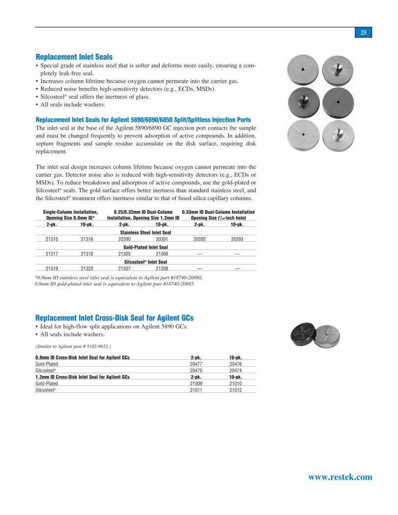
25
www.restek.com
Replacement Inlet Seals• Special grade of stainless steel that is softer and deforms more easily, ensuring a com-
pletely leak-free seal.• Increases column lifetime because oxygen cannot permeate into the carrier gas.• Reduced noise benefits high-sensitivity detectors (e.g., ECDs, MSDs).• Silcosteel® seal offers the inertness of glass.• All seals include washers.
Replacement Inlet Seals for Agilent 5890/6890/6850 Split/Splitless Injection PortsThe inlet seal at the base of the Agilent 5890/6890 GC injection port contacts the sample and must be changed frequently to prevent adsorption of active compounds. In addition, septum fragments and sample residue accumulate on the disk surface, requiring disk replacement.
The inlet seal design increases column lifetime because oxygen cannot permeate into the carrier gas. Detector noise also is reduced with high-sensitivity detectors (e.g., ECDs or MSDs). To reduce breakdown and adsorption of active compounds, use the gold-plated or Silcosteel® seals. The gold surface offers better inertness than standard stainless steel, and the Silcosteel® treatment offers inertness similar to that of fused silica capillary columns.
Single-Column Installation,Opening Size 0.8mm ID*
0.25/0.32mm ID Dual-Column Installation, Opening Size 1.2mm ID
0.53mm ID Dual-Column InstallationOpening Size (1/16-inch hole)
2-pk. 10-pk. 2-pk. 10-pk. 2-pk. 10-pk.
Stainless Steel Inlet Seal21315 21316 20390 20391 20392 20393
Gold-Plated Inlet Seal21317 21318 21305 21306 — —
Silcosteel® Inlet Seal21319 21320 21307 21308 — —
Replacement Inlet Cross-Disk Seal for Agilent GCs• Ideal for high-flow split applications on Agilent 5890 GCs.• All seals include washers.
(Similar to Agilent part # 5182-9652.)
0.8mm ID Cross-Disk Inlet Seal for Agilent GCs 2-pk. 10-pk.Gold-Plated 20477 20476Silcosteel® 20475 204741.2mm ID Cross-Disk Inlet Seal for Agilent GCs 2-pk. 10-pk.Gold-Plated 21009 21010Silcosteel® 21011 21012
*0.8mm ID stainless steel inlet seal is equivalent to Agilent part #18740-20880,0.8mm ID gold-plated inlet seal is equivalent to Agilent part #18740-20885.

26
www.restek.com
Splitless Liners forVarian 1075/1077 GCs Benefits/Uses:
ID**/OD &Length (mm)
Similar toVarian part # ea.
cat.#5-pk. 25-pk.
2mm Splitlesstrace samples <2µL 2.0 ID
6.3 OD x 74 01-900109-05 20721 20722 20723
4mm Splitlesstrace samples >2µL 4.0 ID
6.3 OD x 74 01-900109-05 20904 20905 20906
Double Gooseneck
trace, active samples up to 4µL
4.0 ID6.3 OD x 74 — 20847 20848 20849
Cyclo Double Gooseneck
trace, dirty, active samplesup to 4µL
4.0 ID6.3 OD x 74 — 20897 20898 —
DI Liners for Varian 1075/1077 GCs (0.32/0.53mm ID) Benefits/Uses:
ID**/OD &Length (mm)
Similar toVarian part # ea.
cat.#5-pk. 25-pk.
Uniliner®
trace, active samples,high recovery & linearity
4.0 ID6.3 OD x 72 — 20345 20346 —
Cyclo-Uniliner®
trace, dirty, high MW,active samples, linearity
4.0 ID6.3 OD x 72 — 20347 20348 —
Open-top Uniliner® with Wool*
trace, dirty, active samples,high recovery & linearity
4.0 ID6.3 OD x 72 — 20845 20846 —
SPI Linersfor Varian GCs Benefits/Uses:
ID**/OD &Length (mm)
Similar toVarian part # ea.
cat.#5-pk. 25-pk.
0.5mm SPI
high linearityfor 0.25 & 0.32mm ID columns
0.53 ID4.6 OD x 54 01-900109-06 20775 20776 20777
Siltek™ 0.5mm SPI
high linearityfor 0.25 & 0.32mm ID columns
0.53 ID4.6 OD x 54 01-900109-06 20775-
214.1 20776-214.5 20777-214.25
0.8mm SPI
high linearityfor 0.53mm ID columns
0.80 ID4.6 OD x 54 01-900109-07 20778 20779 20780
SPI with Buffer
dirty samples >1µL, fits 0.25, 0.32 & 0.53mm ID columns
2.4 ID4.6 OD x 54 01-900109-08 20850 20851 20852
CO
LU
MN
I
NS
TA
LL
S
TH
IS
E
ND
featuring
Siltek™deactivation
*Prepacked with fused silica wool. For glass wool instead, add the suffix “-202” to the liner catalog number.**Nominal ID at syringe needle expulsion point.
0 10 %deactivated
all liners are
Split Linersfor 1075/1077 Varian GCs Benefits/Uses:
ID**/OD &Length (mm)
Similar toVarian part # ea.
cat.#5-pk. 25-pk.
1mm Split
purge & trap inlet splitting or samples <1µL
1.0 ID6.3 OD x 72 — 20970 20971 —
Splitter with Wool*
universal, use with rapid autosam-plers
4.0 ID 6.3 OD x 72 01-900109-01 20792 20793 20794
Laminar Cup Splitterhigh MW compounds 4.0 ID
6.3 OD x 72 01-900109-02 20803 20804 —
Cup Splitterhigh & low MW compounds 4.0 ID
6.3 OD x 72 — 20724 20725 —
Cyclosplitter®
dirty samples, many injections before cleaning required
4.0 ID6.3 OD x 72 — 20727 20728 —
Frit Splitter
dirty samples, non-activecompounds
4.0 ID6.3 OD x 72 01-900109-03 20715 20716 20717
Baffle Splitterclose boiling compounds 4.0 ID
6.3 OD x 72 01-900109-04 20718 20719 20720
Split Precision™ Linerdirty samples, active samples 4.0 ID
6.3 OD x 72 — 21030 21031 —
Liners for Varian GCs

27
www.restek.com
1078/1079 Linersfor Varian GCs Benefits/Uses:
ID**/OD &Length (mm)
Similar toVarian part # ea.
cat.#5-pk. 25-pk.
1078/1079 Split
dirty samples, non-activecompounds
3.4 ID5.0 OD x 54 03-918464-00 21708 21709 —
1078/1079 Splitlesstrace samples <2µL 2.0 ID
5.0 OD x 54 03-918466-00 21711 21712 —
Siltek™ 1078/1079 Splitlesstrace samples <2µL 2.0 ID
5.0 OD x 54 03-918466-00 21711-214.1 21712-214.5 —
Open 0.5mm IDtrace samples <1µL 0.5 ID
5.0 OD x 54 03-925331-00 20992 20993 —
1078/1079 Split–No Fritactive samples 3.4 ID
5.0 OD x 54 03-918464-00 20859 20901 20909
Siltek™ 1078/1079 Split–No Fritactive samples 3.4 ID
5.0 OD x 54 03-918464-00 20859-214.1 20901-214.5 20909-
214.25
Open 0.75mm IDtrace, low volume samples 0.75 ID
5.0 OD x 54 03-925330-00 21714 21715 21716
1078/1079 Split Precision™ Linertrace samples, dirty samples 3.4 ID
5.0 OD x 54 — 21024 21025 —
Inlet Liner Removal Tool• Easily remove liners from injectors.• Made from high-temperature silicone.• Won’t chip or crack the liner.
Description qty. cat.#Inlet Liner Removal Tool 3-pk. 20181
CO
LU
MN
I
NS
TA
LL
S T
HI
S E
ND
featuring
Siltek™deactivation
featuring
Siltek™deactivation
Liners forVarian 1177 GCs Benefits/Uses:
ID**/OD &Length (mm)
Similar toVarian part # ea.
cat.#5-pk. 25-pk.
4mm Splituniversal 4.0 ID
6.3 OD x 78.5 39-26119-36 21045 21046 —
2mm Splitless w/wool*trace samples <2µL 2.0 ID
6.5 OD x 78.5 39-26119-38 — 21077 —
4mm Split w/wool*universal 4.0 ID
6.3 OD x 78.5 39-26119-37 — 21079 —
*Prepacked with fused silica wool. For glass wool instead, add the suffix “-202” to the liner catalog number.**Nominal ID at syringe needle expulsion point.
No more burned fingers!
5mm Liner Seals for Varian 1078/1079 GCsDescription qty. cat.#5mm Liner Seals for Varian 1078/1079 GCs 10-pk. 22683
0 10 %deactivated
all liners areLiners for Varian GCs
Inlet Liner Seals for Varian 1177 InjectorsMeets original equipment specifications.(Similar to Varian part # 39-26119-40.)
Description qty. cat.#Inlet Liner Seals for Varian 1177 Injectors 10-pk. 20298

28
www.restek.com
Split Linersfor PerkinElmer GCs Benefits/Uses:
ID**/OD &Length (mm)
Similar toPE part # ea.
cat.#5-pk. 25-pk.
Baffle Splitter
universal, for mostcommon analyses
3.5 ID5.0 OD x 100 0330-5181 20736 20737 —
Cup Splitter
high & low MWcompounds
3.5 ID5.0 OD x 100 — 20739 20740 —
Cyclosplitter®
dirty samples, max.injections before cleaning required
3.5 ID5.0 OD x 100 — 20745 20746 —
Laminar Cup Splitterhigh MW compounds 3.5 ID
5.0 OD x 100 — 20805 20806 —
Auto SYS Splitter with Wool*
universal for mostcommon analyses
4.0 ID6.2 OD x 92.1 N6101052 20832 20833 20834
Siltek™ Auto SYS Splitter w/ Siltek™ Glass Wool
universal for mostcommon analyses
4.0 ID6.2 OD x 92.1 N6101052 20832-213.1 20833-213.5 20834-213.25
Auto SYS Cup Splitter
high & low MWcompounds
4.0 ID6.2 OD x 92.1 — 20835 20836 —
Auto SYS Cyclosplitter®
dirty samples, max.injections before cleaning required
4.0 ID6.2 OD x 92.1 — 20910 20911 —
Auto SYS Laminar Cup Splitterhigh MW compounds 4.0 ID
6.2 OD x 92.1 — 20827 20828 —
Auto SYS Split Precision™ Liner
dirty samples, tracesamples
4.0 ID6.2 OD x 92.1 — 21026 21027 —
Splitless Linersfor PerkinElmer GCs Benefits/Uses:
ID**/OD &Length (mm)
Similar toPE part # ea.
cat.#5-pk. 25-pk.
Splitless (2mm ID)trace samples 2.0 ID
5.0 OD x 100 0330-5180 20730 20731 20732
Auto SYS Splitless w/Wool (2mm ID)*trace samples 2.0 ID
6.2 OD x 92.1 N6101372 20829 20830 20831
Siltek™ Auto SYS Splitless w/Siltek Glass Wool (2mm ID)trace samples 2.0 ID
6.2 OD x 92.1 N6101372 20829-213.1 20830-213.5 20831-213.25
Auto SYS Double Gooseneck
trace, active samplesup to 4µL
4.0 ID6.2 OD x 92.1 — 20853 20854 —
Auto SYS Cyclo Double Gooseneck
trace, dirty, activesamples, up to 4µL
4.0 ID6.2 OD x 92.1 — 20899 20900 —
*Prepacked with fused silica wool. For glass wool instead, add the suffix “-202” to the liner catalog number.**Nominal ID at syringe needle expulsion point.
CO
LU
MN
I
NS
TA
LL
S
TH
IS
E
ND
featuring
Siltek™deactivation
featuring
Siltek™deactivation
DI Liners for PerkinElmer GCs (0.32/0.53mm ID) Benefits/Uses:
ID**/OD &Length (mm)
Similar toPE part# ea.
cat.#5-pk. 25-pk.
Uniliner®
trace, active samples, high recovery &
linearity
3.5 ID5.0 OD x 100 — 20855 20856 —
Cyclo-Uniliner®
trace, dirty, activesamples, high
linearity
3.5 ID5.0 OD x 100 — 20857 20858 —
Auto SYS Open-top Uniliner® w/Wool*
trace, dirty, activesamples, high recov-
ery & linearity
4.0 ID6.2 OD x 92.1 — 20837 20838 —
Auto SYS Cyclo-Uniliner®
trace, dirty, high MW active samples, high linearity
4.0 ID6.2 OD x 92.1 — 20839 20840 —
Auto SYS Drilled Uniliner®
allows direct injec-tion when using an EPC-equipped GC
4.0 ID6.2 OD x 92.1 — 20819 20822 —
0 10 %deactivated
all liners areLiners for PerkinElmer GCs

29
Split Liners forShimadzu GCs Benefits/Uses:
ID**/OD &Length (mm)
Similar toShimadzu part # ea.
cat.#5-pk. 25-pk.
17A 1mm Splitpurge & trap & fast GC 1.0 ID
5.0 OD x 95 — 20976 20977 20978
128mm Split
universal, for mostcommon analyses
3.5 ID5.0 OD x 128 221-25822-01 20751 20752 20753
128mm Cyclosplitter®
dirty samples, manyinjections before cleaning required
3.5 ID5.0 OD x 128 — 20754 20755 —
128mm Cup Splitter
high & low MWcompounds
3.5 ID5.0 OD x 128 — 20757 20758 —
128mm Laminar Cup Splitterhigh MW compounds 3.5 ID
5.0 OD x 128 — 20807 20808 —
99mm Split
universal, for mostcommon analyses
3.5 ID5.0 OD x 99 221-32544-01 20860 20861 20862
99mm Cyclosplitter®
dirty samples, manyinjections before cleaning required
3.5 ID5.0 OD x 99 — 20870 20871 —
99mm Cup Splitterhigh MW compounds 3.5 ID
5.0 OD x 99 — 20866 20867 —
99mm Laminar Cup Splitterhigh MW compounds 3.5 ID
5.0 OD x 99 — 20868 20869 —
17A Split Precision™ Liner
trace samples, dirty samples
3.5 ID5.0 OD x 95 — 21020 21021 —
Splitless Linersfor Shimadzu GCs Benefits/Uses:
ID**/OD &Length (mm)
Similar toShimadzu part # ea.
cat.#5-pk. 25-pk.
128mm Splitless (3mm ID)trace samples 3.5 ID
5.0 OD x 128 221-25440-03 20748 20749 20750
99mm Splitless (3mm ID)trace samples 3.5 ID
5.0 OD x 99 221-32544-00 20863 20864 20865
17A 95mm Double Gooseneck
reduces backflash and catalytic decom-position
3.5 ID5.0 OD x 95 — 20958 20959 20960
17A 95mm Single Gooseneck
reduces backflash, also operates in DI mode
3.5 ID5.0 OD x 95 221-41599-00 20961 20962 20963
Split/Splitless Linersfor Shimadzu GCs Benefits/Uses:
ID**/OD &Length (mm)
Similar toShimadzu part # ea.
cat.#5-pk. 25-pk.
17A 95mm Split/Splitless with Wool*universal, for most common analyses 3.5 ID
5.0 OD x 95 221-41444-00 20955 20956 20957
Siltek™ 95mm Split/Splitless w/ Siltek™ Glass Wooluniversal, for most common analyses 3.5 ID
5.0 OD x 95 221-41444-00 20955-213.1 20956-213.5 20957-
213.25
CO
LU
MN
I
NS
TA
LL
S
TH
IS
E
ND
featuring
Siltek™deactivation
DI Liners forShimadzu GCs (0.32/0.53mm ID) Benefits/Uses:
ID**/OD &Length (mm)
Similar toShimadzu part # ea.
cat.#5-pk. 25-pk.
128mm Uniliner®
trace, active samples, high recovery & linearity
3.5 ID5.0 OD x 128 — 20872 20873 —
128mm Cyclo-Uniliner®
trace, dirty, high MW active samples, high linearity
3.5 ID5.0 OD x 128 — 20874 20875 —
99mm Uniliner®
trace, active samples, high recovery & linearity
3.5 ID5.0 OD x 99 — 20876 20877 —
99mm Cyclo-Uniliner®
trace, dirty, high MW active samples, high recovery & linearity
3.5 ID5.0 OD x 99 — 20893 20894 —
95mm Uniliner® with Wool*
trace, dirty, high MW active samples, high recovery & linearity
3.5 ID5.0 OD x 95 — 21713 21719 —
*This liner is prepacked with fused silica wool. To order glass wool instead, add the suffix “-202” to the liner catalog number.**Nominal ID at syringe needle expulsion point.
Liners for Shimadzu GCs0 10 %deactivated
all liners are

30
www.restek.com
Split Liners for5000-6000 Series GCs Benefits/Uses:
ID**/OD &Length (mm)
Similar toTF part # ea.
cat.#5-pk. 25-pk.
Laminar Cup Splitterhigh MW compounds 4.0 ID
5.4 OD x 79.5 — 20809 20810 —
Cyclosplitter®
dirty samples, many injections before cleaning required
4.0 ID5.4 OD x 79.5 — 20817 20818 —
Cup Splitter Gooseneck
high & low MW compounds
4.0 ID5.4 OD x 79.5 — 20885 20886 —
Splitless Liners for8000 & TRACE™ Series GCs Benefits/Uses:
ID**/OD &Length (mm)
Similar toTF part # ea.
cat.#5-pk. 25-pk.
Splitless (3mm ID)trace samples 3.0 ID
8.0 OD x 105 453 20032 20942 20943 20944
Siltek™ Splitless (3mm ID)trace samples 3.0 ID
8.0 OD x 105 453 20032 20942-214.1 20943-214.5 20944-214.25
Splitless (5mm ID)trace samples 5.0 ID
8.0 OD x 105 453 20033 20945 20946 20947
Double Gooseneck
trace active samples up to 4µL
4.0 ID8.0 OD x 105 — 20952 20953 —
Split Liners for8000 & TRACE™ Series GCs Benefits/Uses:
ID**/OD &Length (mm)
Similar toTF part # ea.
cat.#5-pk. 25-pk.
1mm Splitpurge & trap & fast GC 1.0 ID
8.0 OD x 105 453 20075 20916 20917 —
3mm Splituniversal 3.0 ID
8.0 OD x 105 453 20031 20936 20937 20938
5mm Splituniversal 5.0 ID
8.0 OD x 105 453 20030 20939 20940 20941
Laminar Cup Splitterhigh MW compounds 4.0 ID
8.0 OD x 105 — 20948 20949 —
Cup Splitter
high & low MW compounds
4.0 ID8.0 OD x 105 — 20950 20951 —
5mm Split Precision™ Liner
trace samples, dirty samples
5.0 ID8.0 OD x 105 — 21028 21029 —
DI Liners for 5000-6000 Series GCs (0.32/0.53 ID) Benefits/Uses:
ID**/OD &Length (mm)
Similar toTF part # ea.
cat.#5-pk. 25-pk.
Open-top Uniliner® w/Wool*
trace, dirty, active samples,
high recovery & linearity
4.0 ID5.4 OD x 79.5 — 20841 20842 —
*Prepacked with fused silica wool. For glass wool instead, add the suffix “-202” to the liner catalog number.**Nominal ID at syringe needle expulsion point.
CO
LU
MN
I
NS
TA
LL
S
TH
IS
E
ND
Splitless Liners for5000-6000 Series GCs Benefits/Uses:
ID**/OD &Length (mm)
Similar toTF part # ea.
cat.#5-pk. 25-pk.
Splitless (2mm ID)trace samples 2.0 ID
5.4 OD x 79.5 — 20811 20812 20813
Splitless (4mm ID)trace samples 4.0 ID
5.4 OD x 79.5 — 20814 20815 20816
featuring
Siltek™deactivation
0 10 %deactivated
all liners areLiners for Thermo Finnigan

31
www.restek.com
Split Liners forTRACE™ 2000 GCs Benefits/Uses:
ID**/OD &Length (mm)
Similar toTF part # ea.
cat.#5-pk. 25-pk.
1mm ID Trace 2000 Glass Liner
trace samples, high recovery & linearity
1mm ID 2.95 OD x 120 — 21114 21115 —
2mm ID Trace 2000 Glass Lineruniversal 2mm ID
2.95 OD x 120 — 21116 21117 —
CO
LU
MN
IN
ST
AL
LS
TH
IS E
ND
Inlet Liner Seal for TRACE™ 2000 GCsDescription qty. cat.#Inlet Liner Seal 2-pk. 21392
**Nominal ID at syringe needle expulsion point.
Liners for Thermo FinniganDI Liners for
8000 & TRACE™ Series GCs Benefits/Uses:ID**/OD &
Length (mm)Similar toTF part # ea.
cat.#5-pk. 25-pk.
Uniliner® w/Wool
trace, active samples, high recovery,
& linearity
5.0 ID8.0 OD x 105 — 21005 21006 —
0 10 %deactivated
all liners are
Graphite Sealing Ring and Washer for 8000 Series and TRACE™ GC Inlet Liners(Similar to Thermo Finnigan part # 290-03406)
Description qty. cat.#Graphite Sealing Ring and Washer ea. 21898Graphite Sealing Rings and Washers 2-pk. 21899
Graphite Ferrules for M4 Fittings• High-purity, high-density graphite.• Smoother surface and cleaner edges than conventional graphite ferrules.• Contain no binders that can off-gas or adsorb analytes.• Stable to 450°C.
*0.4mm ID ferrule is similar to Thermo Finnigan part #290-13488, 0.5mm ID ferrule is similar to Thermo Finnigan part #290-13487, and 0.8mm ID ferrule is similar to Thermo Finnigan part #290-13486.
Graphite Ferrules for M4 Fittings for QCQ Thermo Finnigan 8000 & TRACE™ 2000Ferrule Fits Column Graphite Graphite
ID ID 2-pk. 10-pk.0.4mm* 0.18–0.25mm 20280 202810.5mm* 0.28/0.32mm 20282 202830.8mm* 0.45/0.50 & 0.53mm 20284 20285
Graphite Ferrules for M4 Fittings for QCQ Thermo Finnigan 8000 & TRACE™ 2000

32
www.restek.com
InfraRed™ Septa• Usable to 325°C inlet temperatures.• Preconditioned and ready to use.• Excellent puncturability.• Do not adhere to hot metal surfaces.• Low bleed.• Packaged in non-contaminating glass jars.
IceBlue™ Septa• Usable to 250°C inlet temperatures.• General-purpose septa.• Excellent puncturability.• Preconditioned and ready to use.• Do not adhere to hot metal surfaces.• Packaged in non-contaminating glass jars.• Ideal for SPME.
Septum Diameter 25-pk. 50-pk. 100-pk.9mm 21417 21418 214199.5mm (3/8") 21421 21422 2142310mm 21424 21425 2142611mm (7/16") 21427 21428 2142911.5mm 21430 21431 2143212.5mm (1/2") 21433 21434 2143517mm 21436 21437 21438Shimadzu Plug 21439 21440 21441
Septum Diameter 50-pk. 100-pk.9mm 22381 223829.5mm (3/8") 22388 2238910mm 22390 2239111mm (7/16") 22392 2239311.5mm 22383 2238412.5mm (1/2") 22394 2239517mm 22396 22397Shimadzu plug 22398 22399
Instrument Septum Size Agilent (HP)5880A, 5890, 6890,6850 11mm5700, 5880 9.5/10mmOn-Column Injection 5mm CE Instruments (TMQ)TRACE GC 17mm Finnigan (TMQ)GC 9001 9.5mmGCQ 9.5mmGCQ w/TRACE 17mmQCQ™ 9.5mmTRACE 2000 9.5mm Fisons/Carlo Erba
(TMQ)8000 series 17mm Gow-Mac 6890 series 11mmAll other models 9.5mm PerkinElmerSigma series 11mm900,990 11mm8000 series 11mmAuto SYS 11mmAuto SYS XL 11mm Pye/UnicamAll models 7mm ShimadzuAll models Plug SRIAll models Plug Tracor540 11.5mm550,560 9.5mm220,222 12.5mm VarianInjector type:Packed column 9.5/10mmSplit/splitless 1078/1079 10/11mm1177 9mm1075/1077 11mm
Septum Size Charthandy Thermolite® Septa
• Usable to 340°C inlet temperatures.• Each batch tested on FIDs, ECDs, and MSDs to ensure lowest bleed.• Excellent puncturability.• Preconditioned and ready to use.• Do not adhere to hot metal surfaces.• Packaged in non-contaminating glass jars.
Septum Diameter 25-pk. 50-pk. 100-pk.5mm (3/16") 20351 20352 203536mm (1/4") 20355 20356 203577mm 20381 20382 203838mm 20370 20371 —9mm 20354 20358 203629.5mm (3/8") 20359 20360 2036110mm 20378 20379 2038011mm (7/16") 20363 20364 2036511.5mm 22385 22386 2238712.5mm (1/2") 20367 20368 2036917mm 20384 20385 20386Shimadzu Plug 20372 20373 20374

33
www.restek.com
Siltek™ Press-Tight® Connectors• Siltek™ deactivation for inert pathways to maintain sample integrity.• Ideal for connecting guard columns to analytical columns.• Angled Press-Tight® connector designed at an angle approximating the curvature of a
capillary column to reduce strain on column-end connections.• Fits 0.18, 0.25, 0.32, & 0.53mm ID columns.
Siltek™ Press-Tight™ ConnectorsPress-Tight® Connector ea. 3-pk. 5-pk. 25-pk. 100-pk.Universal Press-Tight® Connector — — 20480 20449 20481Universal Angled Press-Tight® Connector — — 20482 20483 20484Universal “Y” Press-Tight® Connector 20485 20486 — — —Universal Angled “Y” Press-Tight® Connector 20487 20469 — — —
Universal Angled Press-Tight® Connectors• Designed at an angle approximating the curvature of a capillary column.• Reduces strain on column-end connections.• Ideal for connecting guard columns to analytical columns.• Seals all common sizes of fused silica tubing (0.18 to 0.53mm ID, outside diameters
from 0.3 to 0.75mm).• Made from inert fused silica.
Description qty. cat.#Universal Angled Press-Tight® Connectors 5-pk. 20446Universal Angled Press-Tight® Connectors 25-pk. 20447Universal Angled Press-Tight® Connectors 100-pk. 20448
Universal Press-Tight® Connectors• Connect guard columns to analytical columns.• Repair broken columns.• Connect column outlets to transfer lines.
Description qty. cat.#Universal Press-Tight® Connectors 5-pk. 20400Universal Press-Tight® Connectors 25-pk. 20401Universal Press-Tight® Connectors 100-pk. 20402
Deactivated, Universal Press-Tight® Connectors• High-temperature silanization for excellent inertness. • Ideal for trace analysis of active compounds.• Ideal for analysis of pesticides, semivolatile pollutants, or clinical/forensic samples.
Description qty. cat.#Deactivated, Universal Press-Tight® Connectors 5-pk. 20429Deactivated, Universal Press-Tight® Connectors 25-pk. 20430Deactivated, Universal Press-Tight® Connectors 100-pk. 20431
Universal “Y” Press-Tight® Connectors• Split sample flow onto two columns.• Split a single column flow into two detectors—
perform confirmational analysis with a single injection.
• Fit 0.18, 0.25, 0.32, & 0.53mm ID columns.
Description qty. cat.#Universal “Y” Press-Tight® Connector ea. 20405Universal “Y” Press-Tight® Connectors 3-pk. 20406
Siltek™—the mostinert deactivation available!
Polyimide Resin• Permanently connects a Press-
Tight® connector to a fused silica column.
• 350°C maximum operating tem-perature.
Description qty. cat.#
Polyimide Resin 5 grams 20445

34
www.restek.com
MXT®-Union Connector Kits—For Fused Silica Columns• Low-dead-volume,leak-freeconnection.• Reusable.• Silcosteel®treatmentensuresmaximuminertness.• Idealforconnectingguardcolumnsandtransferlines.• Usetooventemperaturesof350°C.• Availableinunionand“Y”configurations.
Previously, easy-to-use MXT® connectors could only be used with metal tubing. NowMXT®connectorscanbeusedwith fusedsilicacapillarycolumns,becauseofaValconpolyimide1/32-inchone-piecefusedsilicaadaptor.Thisuniquegraphite-reinforcedcompos-iteallowscapillarycolumnstoslideintoandbelockedinplacesimplybylooseningandtighteningtheMXT®union1/32-inchfitting.
MXT®-Union Connector Kits—For Fused Silica ColumnsEachkitcontainstheMXT®union,two1/32-inchnutsandtwoone-piecefusedsilicaadaptors.
Description qty. cat.#For 0.25mm ID Fused Silica Columns kit 21386For 0.32mm ID Fused Silica Columns kit 21385For 0.53mm ID Fused Silica Columns kit 21384
MXT® “Y”-Union Connector Kits—For Fused Silica ColumnsEachkitcontainstheMXT®union,three1/32"nutsandthreeone-piecefusedsilicaadaptors.
Description qty. cat.#For 0.25mm ID Fused Silica Columns kit 21389For 0.32mm ID Fused Silica Columns kit 21388For 0.53mm ID Fused Silica Columns kit 21387
1/32-Inch Replacement NutDescription qty. cat.#1/32" Replacement Nut 5-pk. 20389
Valco® Connectors—One-Piece Fused Silica Adaptor FerruleWerecommendaone-pieceadaptorferruleforuseinfittingswheretheferrulewillnotberemoved.Connectionsaremadeanddisconnectedbylooseningthefittingnutandslidingthetubeout.FusedsilicaadaptorferrulesareavailableinValconpolyimideforuseupto350°C.Valconpolyimideisauniquegraphite-reinforcedcomposite,speciallypreparedtomaximizemechanicalstabilityathightemperatures.Thedeterminingfactorinadaptorfer-rulesizeselectionisthefusedsilicatubingouterdiameter(OD).
1/32-Inch Adaptor FerruleValcon Polyimide
Tubing OD Tubing ID Valco® # qty. cat.#<0.25–0.4mm 0.25mm FS.4-5 5-pk. 201370.4–0.5mm 0.32mm FS.5-5 5-pk. 201400.5–0.8mm 0.53mm FS.5V-5 5-pk. 20141
1/32" Replacement Nut 5-pk. 20389
Gerstel GRAPHPACK® 3D/2 ConnectorsGRAPHPACK®technologyprovidesacompletesystemthatquicklyandreliablymakesleak-free,low-dead-volumeconnections.Thecentralcomponentisametal-jacketedgraph-iteferrule—theidealsealforGCapplications.GRAPHPACK®ferruleseliminateall thedisadvantagesandshortcomingsassociatedwithprevioussealingsystems.
**Use only with GRAPHPACK® 3D/2 ferrules.
Ideal for MXT® stainless steel to fused silica capillary connections!
Description qty. cat.#
GRAPHPACK® 3D/2 Connector**(0.25mm to 0.32mm ID) ea. 20272
GRAPHPACK® 3D/2 Connector**(0.45mm to 0.7mm ID) ea. 20273
Use for fused silica-to-fused silica or fused silica-to-metal connections!
GRAPHPACK® 3D/2 FerrulesFerrule ID Fits Column ID qty. cat.#0.4mm 0.25mm 10-pk. 202710.5mm 0.32mm 10-pk. 202700.8mm 0.45/0.53mm 10-pk. 20274

35
www.restek.com
MXT® Guard Columns/Transfer LinesNominal ID Nominal OD 5-Meter 5-Meter/6-pk. 10-Meter0.28mm 0.53 ± 0.025mm 70044 70044-600 700460.53mm 0.74 ± 0.025mm 70045 70045-600 70047
Fused Silica Guard Columns/Transfer Lines
*Not tested with the Grob test mix because of a high pressure drop.**30- and 60-meter lengths are banded in 5-meter sections.†Recommendation: Cut 60m guard columns into shorter lengths. Using full length may cause peak dis-tortion.
Nominal ID Nominal OD 1-Meter 5-Meter 5-Meter/6-pk.0.025mm* 0.363 ± 0.012mm 100970.05mm 0.363 ± 0.012mm 10098 10040 10040-600
0.075mm* 0.363 ± 0.012mm 100990.10mm 0.363 ± 0.012mm 10100 100410.15mm 0.363 ± 0.012mm 10101 100420.18mm 0.37 ± 0.04mm 10102 100460.25mm 0.37 ± 0.04mm 10043 10043-6000.28mm 0.37 ± 0.04mm 10003 10003-6000.32mm 0.45 ± 0.04mm 10044 10044-6000.45mm 0.69 ± 0.04mm 10005 10005-6000.53mm 0.69 ± 0.05mm 10045 10045-600
Intermediate-Polarity Deactivated Guard Columns & Transfer Lines• Useful for a wide range of applications.• Compatible with most common solvents.
Nominal ID Nominal OD 10-Meter 10-Meter/6-pk. 30-Meter** 60-Meter**†0.25mm 0.37 ± 0.04mm 10049 10049-600 10012 100130.32mm 0.45 ± 0.04mm 10048 10048-600 10022 100230.53mm 0.69 ± 0.05mm 10047 10032 10033
Siltek™-Deactivated Guard Columns• Revolutionary deactivation process lowers analyte breakdown to less than 1%.• Minimizes bleed.• Ideal for chlorinated pesticide analysis.• Analyze tough samples quickly and accurately.• Maximum temperature of 380°C.
Siltek™-Deactivated Guard ColumnsNominal ID Nominal OD 5-Meter 10-Meter
0.25mm 0.37 ± 0.04mm 10026 100360.32mm 0.45 ± 0.04mm 10027 100370.53mm 0.69 ± 0.05mm 10028 10038
Let Restek Make the Connection for You!Restek will connect a Siltek™ guard column to any analytical column using a universal Siltek™ Press-Tight® connector and polyimide sealing resin. To order a preconnected guard column, add the three-digit suffix from the chart below to any analytical column catalog number when ordering.
A 5m, 0.32mm ID Siltek™ guard column connected to a 30m, 0.32mm ID, 1.0µm Rtx®-5 column is cat.# 10254-365.
Example:5m Siltek™ Guard Column/Transfer Line
ID cat.# suffix0.25mm -3640.32mm -3650.53mm -366

PATENTS.&.TRADEMARKSRestek.patents.and.trademarks.are.the.property.of.Restek.Corporation..Other.trademarks.appearing.in.Restek.literature.or.on.its.website.are.the.property.of.their.respective.owners.
Restek U.S. • 110 Benner Circle • Bellefonte, PA 16823 • 814-353-1300 • 800-356-1688 • fax: 814-353-1309 • www.restek.comRestek France • phone: +33 (0)1 60 78 32 10 • fax: +33 (0)1 60 78 70 90 • e-mail: [email protected] GmbH • phone: +49 (0)6172 2797 0 • fax: +49 (0)6172 2797 77 • e-mail: [email protected] Ireland • phone: +44 (0)2890 814576 • fax: +44 (0)2890 814576 • e-mail: [email protected] Japan • phone: +81 (3)6459 0025 • fax: +81 (3)6459 0025 • e-mail: [email protected] Restek U.K. LTD • phone: +44 (0)1494 563377 • fax: +44 (0)1494 564990 • e-mail: [email protected]
Lit. Cat.# 59880A© 2002 Restek Corporation.