opera t multi-purpose lcd display mu-170c clearing the memory.....20 specifications.....sp-1...
TRANSCRIPT

OPER
ATOR
'S MA
NUA
L
Multi-purpose LCD Display
MU-170C
IMPORTANT NOTICE
• No part of this manual may be copied or reproduced without written permission.
• If this manual is lost or worn, contact your dealer about replacement.
• The contents of this manual and equipment specifications are subject to change without notice.
• The example screens (or illustrations) shown in this manual may not match the screens you see on your display. The screen you see depends on your system configuration and equipment settings.
• This manual is intended for use by native speakers of English.
• FURUNO will assume no responsibility for the damage caused by improper use or modification of the equipment or claims of loss of profit by a third party.
• Please carefully read and follow the operation and maintenance procedures set forth in this manual.
• Store this manual in a convenient place for further reference.
i
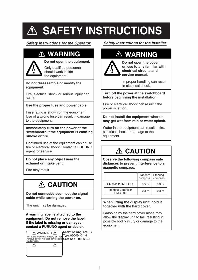
SAFETY INSTRUCTIONSSafety Instructions for the Operator Safety Instructions for the Installer
WARNING
CAUTION
A warning label is attached to the equipment. Do not remove the label.If the label is missing or damaged,contact a FURUNO agent or dealer.
WARNINGTo avoid electrical shock, do not remove cover. No user-serviceable parts inside.
Name: Warning Label (1)Type: 86-003-1011-1Code No.: 100-236-231
WARNING
CAUTION
LCD Monitor MU-170C
Standard Steeringcompass compass
0.3 m 0.3 mRemote ControllerRMC-200
Do not open the equipment.
Only qualified personnelshould work insidethe equipment.
Do not disassemble or modify theequipment.
Fire, electrical shock or serious injury canresult.
Use the proper fuse and power cable.
Fuse rating is shown on the equipment.Use of a wrong fuse can result in damageto the equipment.
Immediately turn off the power at theswitchboard if the equipment is emittingsmoke or fire.
Continued use of the equipment can causefire or electrical shock. Contact a FURUNOagent for service.
Do not place any object near theexhaust or intake vent.
Fire may result.
Do not connect/disconnect the signalcable while turning the power on.
The unit may be damaged.
Do not open the coverunless totally familiar withelectrical circuits andservice manual.
Improper handling can resultin electrical shock.
Turn off the power at the switchboardbefore beginning the installation.
Fire or electrical shock can result if thepower is left on.
Do not install the equipment where itmay get wet from rain or water splash.
Water in the equipment can result in fire,electrical shock or damage to the equipment.
Observe the following compass safedistances to prevent interference to amagnetic compass:
When lifting the display unit, hold ittogether with the hard cover.
Grasping by the hard cover alone mayallow the display unit to fall, resulting inpossible bodily injury or damage to theequipment.
0.5 m 0.3 m

ii
TABLE OF CONTENTS
FOREWORD ........................................................................................................ iii
SYSTEM CONFIGURATION................................................................................ iv
EQUIPMENT LISTS .............................................................................................. v
1. MOUNTING ....................................................................................................... 1 1.1 Display Unit .....................................................................................................................1 1.2 Remote Controller ...........................................................................................................4
2. WIRING ............................................................................................................. 5
3. ADJUSTMENTS................................................................................................ 7 3.1 RGB/DVI Setting .............................................................................................................7 3.2 VIDEO Setting.................................................................................................................9 3.3 Menu Window Setting ...................................................................................................10
3.3.1 Adjusting the menu window................................................................................10 3.3.2 Changing the signal name.................................................................................. 11
3.4 Remote Controller Setting .............................................................................................12
4. OPERATION.................................................................................................... 13 4.1 Controls.........................................................................................................................13 4.2 Adjusting Display Brilliance............................................................................................15 4.3 Choosing Source for Main Picture .................................................................................16 4.4 Choosing Source for Picture-in-Picture..........................................................................17
5. MAINTENANCE, TROUBLESHOOTING ....................................................... 18 5.1 Maintenance..................................................................................................................18 5.2 Troubleshooting.............................................................................................................19 5.3 Clearing the Memory .....................................................................................................20
SPECIFICATIONS........................................................................................... SP-1
Declaration of Conformity
PACKING LISTS ............................................................................................... A-1
OUTLINE DRAWINGS ...................................................................................... D-1
INTERCONNECTION DIAGRAM ......................................................................S-1

iii
FOREWORD
A Word to the Owner of the MU-170C FURUNO Electric Company thanks you for purchasing the MU-170C 17” Multi-Purpose LCD Display. We are confident you will discover why the FURUNO name has become synonymous with quality and reliability. For over 50 years FURUNO Electric Company has enjoyed an enviable reputation for quality and reliability throughout the world. This dedication to excellence is furthered by our extensive global network of agents and dealers. Your equipment is designed and constructed to meet the rigorous demands of the marine environment. However, no machine can perform its intended function unless properly installed and maintained. Please carefully read and follow the operation, installation and maintenance procedures set forth in this manual. We would appreciate feedback from you, the end-user, about whether we are achieving our purposes. Thank you for considering and purchasing FURUNO.
Features • Main or remote display for radars, video sounders, sonars, plotter. Compatible
equipment: FAR-21X7 series, NavNet vx2, FCV-1200L/1200LM, CH-250, CH-270, CSH-5L/8L, GD-280/380/680, etc.
• High resolution display of 1280 x 1024 dot (SXGA)
• Brightness of 1000 cd/m2 (maximum) and 2 cd/m2
or less (minimum) for comfortable viewing day and night
• Landscape orientation
• Picture-in-picture function

iv
SYSTEM CONFIGURATION
12-24 VDC
CCD camera, Video cassette recorder, etc.
FAR-21X7 series, etc.
Radar, Video Plotter,Navigator, Video Sounder, Scanning Sonar, etc.
RGB
DVI
VIDEO (NTSC/PAL)
Connectable equipment
Equipment Resolution Signal FCV-1200L/1200LM* VGA** Analog, via IF-8000
CH-250 VGA** Analog, via IF-8000
CH-270 VGA** Analog, via IF-8000
CSH-5L/8L XGA** Analog
FSV-24/24S SXGA Analog
GD-280/380/680 VGA** Analog
FR-1500 MK3 series XGA** Analog
FR-21X5 series SXGA Analog
FAR-21X7 series SXGA DVI
NavNet vx2 VGA** Analog *: Not useable with the portrait type. **: When inputting VGA, SVGA or XGA, the circle may be displayed as an ellipse because
the aspect ratio differs. In this case, select NORMAL from the DISP MODE menu item on the RGB1, 2 or DVI menus. The top and bottom on the screen are blank, but it is normal.
The TFT LCD is constructed using thelatest LCD techniques, and displays 99.99% of its pixels. The remaining 0.01%of the pixels may drop out or blink, how-ever this is not an indication of malfunc-tion.
About the TFT LCD

v
EQUIPMENT LISTS
Standard supply Name Type Code No. Qty Remarks
Display Unit MU-170C - 1 w/hard cover Remote Controller Set* RMC-200 000-012-629 1 set Spare Parts* SP19-00401 001-416-700 1 set Installation Materials* CP19-00500 000-012-654 1 set Accessories* FP19-01001 001-416-740 1 set
*: See packing list of this manual. Option
Name Type Code No. Qty Remarks 3COX-2P-6C 5M 000-146-500 1 Cable length: 5 m
3COX-2P-6C 10M 000-146-501 1 Cable length: 10 m Cable Assy
DVI-D/D SINGLELINK5M 000-149-054 1 Cable length: 5 m Bracket kit for Monitor MU-170C Hanger 000-153-819 1 set See page 3.
Remote Controller Set
RMC-200 000-012-629 1 set

1
1. MOUNTING
Refer to the outline drawing of this manual for mounting dimensions. Note: The face of the LCD monitor is made of glass. Handle it with care.
1.1 Display Unit The display unit may be mounted on a desktop (optional bracket kit required) or flush mounted in a panel. When selecting a mounting location, keep in mind the following points:
• Locate the unit out of direct sunlight.
• The unit weighs 7.5 kg (flush mounting) or 12.9 kg (desktop mounting). Be sure the mounting location is strong enough to support the weight of the unit.
• Select a location where the display can be easily viewed and the controls can be easily operated.
• Leave sufficient space around the unit for servicing and maintenance. See the outline drawing for minimum service clearance.
• Locate the unit away from areas subject to water splash and rain.

2
Flush mounting See the outline drawing of this manual for mounting dimensions.
CAUTIONHold the hard cover and display unittogether when lifting the display unit.
The display unit may fall out if only the hard cover is held.
1. Remove the hard cover and four cosmetic caps from the unit. 2. Using the paper template supplied, make a cutout in the mounting location. 3. Set the display unit to the cutout, and fasten it with four self-tapping screws (5x40,
supplied as accessories).
Note: Hex head bolts may also be used to fasten the display unit. However, their lengths must project 10 mm from the wall.
Waterproofing: IP20Waterproofing: IP56, CFR46
30 98
Cosmetic cap
Minimum: 50
Flush mounting
4. Attach the cosmetic caps and the hard cover to the display unit.

3
Desktop mounting The display unit can be mounted on a desktop, using the optional bracket kit (Type: MU-170C Hanger, Code No.: 000-153-819).
Contents of bracket kit
Name Qty Hanger L 1 Hanger R 1 Pole 1 Hole plug 2 Hex bolt (M10x30) 2 Flat washer (M10) 2 Spring washer (M10) 2 Hex bolt (M5x25) 4 Flat washer (M5) 4 Spring washer (M5) 4
1. Assemble two hangers and pole with two hex bolts (M10x30), spring washers and flat
washers, and cover holes for hex bolts with the hole plugs. 2. Fix the above assembly to the mounting location with four hex bolts (M10, dockyard
supply).
Note: Do not mount the unit where the exhaust or intake vent may be obstructed.
3. Remove the hard cover and four cosmetic
caps from the unit. 4. Set the display unit to the assembled
hanger, and fasten it with four hex bolts (M5x25), spring washers and flat washers. 5. Attach the cosmetic caps and the hard cover to the display unit.
Hanger LM10 bolts for fixing(Dockyard supply)
PoleHanger R
Flat washer (M10)
Spring washer (M10)
Hex bolt(M10x30)
Hole plug
To remove this cosmetic cap, insert fingernail in groove.
Desktop mounting
Hex bolt (M5x25)Spring washer (M5)
Flat washer (M5)
Intake vent Exhaust vent
Display unit (rear view)
4
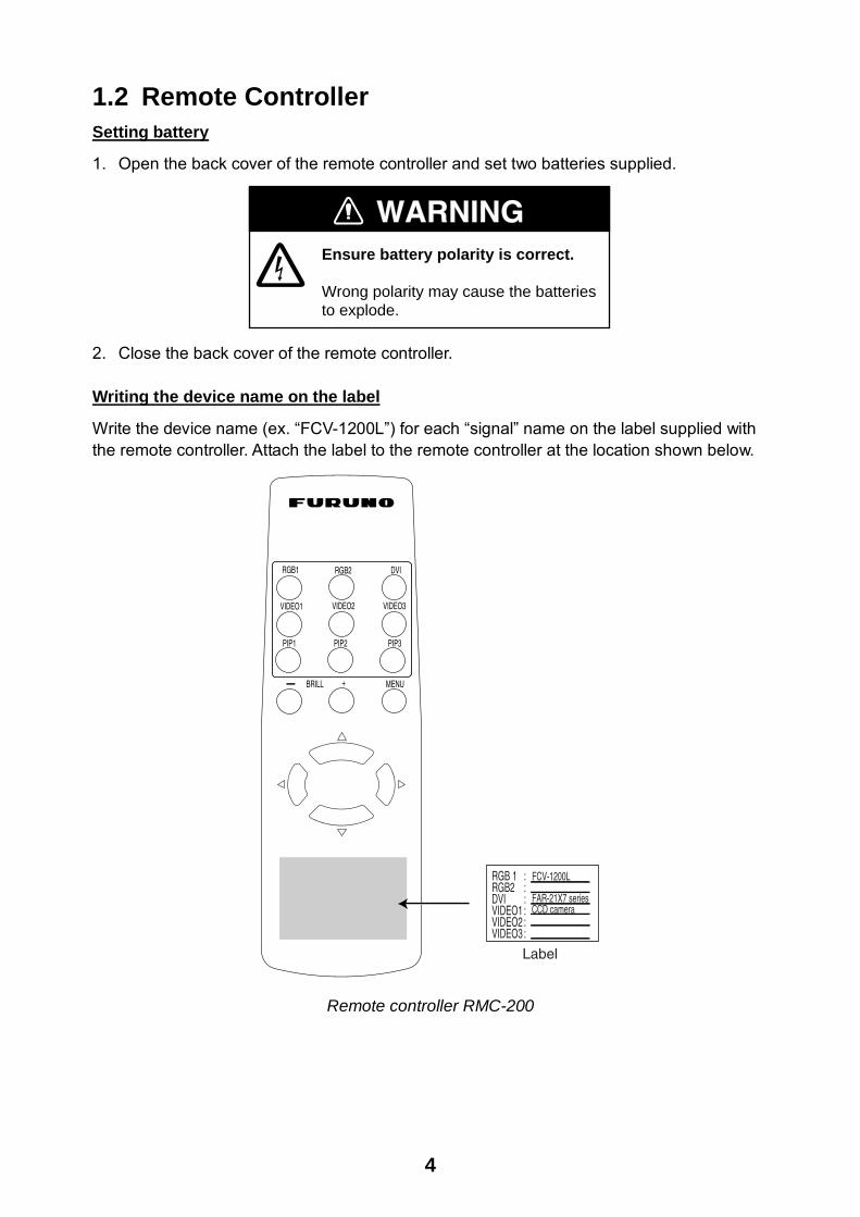
1.2 Remote Controller Setting battery
1. Open the back cover of the remote controller and set two batteries supplied.
WARNINGEnsure battery polarity is correct.
Wrong polarity may cause the batteriesto explode.
2. Close the back cover of the remote controller. Writing the device name on the label
Write the device name (ex. “FCV-1200L”) for each “signal” name on the label supplied with the remote controller. Attach the label to the remote controller at the location shown below.
Label
VIDEO2VIDEO1
BRILL +
RGB1 RGB2
MENU
VIDEO3
DVI
PIP1 PIP2 PIP3
RGB 1 :RGB2 :DVI :VIDEO1 :VIDEO2 :VIDEO3 :
FCV-1200L
FAR-21X7 seriesCCD camera
Remote controller RMC-200

5
2. WIRING
Connect external equipment to the MU-170C by referring to the drawing below, the table on the next page and the interconnection diagram in this manual.
Note: The MU-170C does not have a “hot plug” function. Therefore, when the power switch
of the MU-170C and the equipment connected to it are on, do not connect or disconnect the interconnection cable to prevent damage to equipment.
DVI-D
TB-1
RGB1
RGB2
VIDEO1
VIDEO3
VIDEO2
Fuse( )(+)
RedBlue
14AWG-2C-PVC *5M*(Supplied)
12-24 VDC
Ground terminal
DVI-D/D SINGLELINK5M(Option)
FAR-21X7 series
CCD camera,Video cassette recorder, etc. 2.5C2V or 3C2V
(Local supply)
3COX-2P-6C (Option)
FCV-1200L/1200LMCH-250CH-270CSH-5L/8LFSV-24/24SGD-280/380/680FR-1500 MK3 seriesFR-21X5 seriesNavNet vx2
Display unit (bottom view)

6
Port, cable and connectable equipment
Used cable Port Name Name Type Code No. Standard/
Option
Connectable Equipment
TB-1 Power cable
14AWG-2C-PVC *5M* 000-154-337 Standard Power source
DVI-D DVI Cable
DVI-D/D SINGLELINK5M 000-149-054 Option PC,
FAR-21X7 series
RGB1 3COX-2P-6C 5M 000-146-500 Option
RGB2
Analog RGB Cable
3COX-2P-6C 10M 000-146-501 Option
FCV-1200L/1200LM, CH-250, CH-270, CSH-5L/8L, FSV-24/24S, GD-280/380/680, FR-1500 MK3 series, FR-21X5 series, NavNet vx2
VIDEO1
VIDEO2
VIDEO3
Prepare the following cable locally. Connector type: RCA (metal), both ends Cable length: Max. 10 m 2.5C2V or 3C2V (Japan Industrial Standard, or the equivalent) coaxial cable (Impedance: 75 Ω)
ConductorS = 0.19 mm∅ = 0.5 mm
2
Shield
Insulator
Vinylsheath
Cable 3C2V
Video cassette recorder, CCD camera, DVD player
Grounding Fasten a ground wire (dockyard supply) and the gray crimp-on lug of the power cable to the ground terminal together. The length of the ground wire should be as short as possible. Note: Use a “closed-type” lug ( ) to make the ground connection. Do not use an
“open-type” lug ( ).

7
3. ADJUSTMENTS
Adjust the MU-170C according to the equipment connected.
3.1 RGB/DVI Setting RGB1 and RGB2 screens can be adjusted independently. Also, DVI screen can be adjusted similarly.
1. Adjust the display currently selected, at the DISP selection window. (See section 4.3.) 2. Press the MENU key to show the main menu.
The main menu disappears if there is no operation for one minute. 3. Press the or key to select RGB1, RGB2 or DVI as appropriate.
The items on the RGB1 menu are duplicated on the RGB2 menu.
RGB1 (RGB2) setting menu
DVI setting menu
4. Press the or key to select the item to adjust. 5. Press the or key to adjust. 6. Press the MENU key to close the menu.
RGB1 RGB2 DVI VIDEO1 VIDEO2 VIDEO3 OSD SYSTEM H_SIZE 640 V_SIZE 480 PHASE 16 (1 – 32) CONTRAST 44 (1 – 64) H_POSITION 50 (1 – 99) V_POSITION 25 (1 – 40) R_LEVEL 31 (1 – 64) G_LEVEL 31 (1 – 64) B_LEVEL 31 (1 – 64) TEMPERATURE 7000K (5500K/6500K/7000K/8000K) B STRETCH OFF (OFF, 1 – 10) W STRETCH OFF (OFF, 1 – 10) DISP MODE FULL (FULL/EVEN/NORMAL) SHARPNESS 5 (1 – 10)
RGB1 RGB2 DVI VIDEO1 VIDEO2 VIDEO3 OSD SYSTEM
CONTRAST 44 (1 – 64)H_POSITION 25 (1 – 50) V_POSITION 25 (1 – 40) R_LEVEL 31 (1 – 64) G_LEVEL 31 (1 – 64) B_LEVEL 31 (1 – 64) TEMPERATURE 7000K (5500K/6500K/7000K/8000K) B STRETCH OFF (OFF, 1 – 10) W STRETCH OFF (OFF, 1 – 10) DISP MODE FULL (FULL/EVEN/NORMAL) SHARPNESS 5 (1 – 10)
8
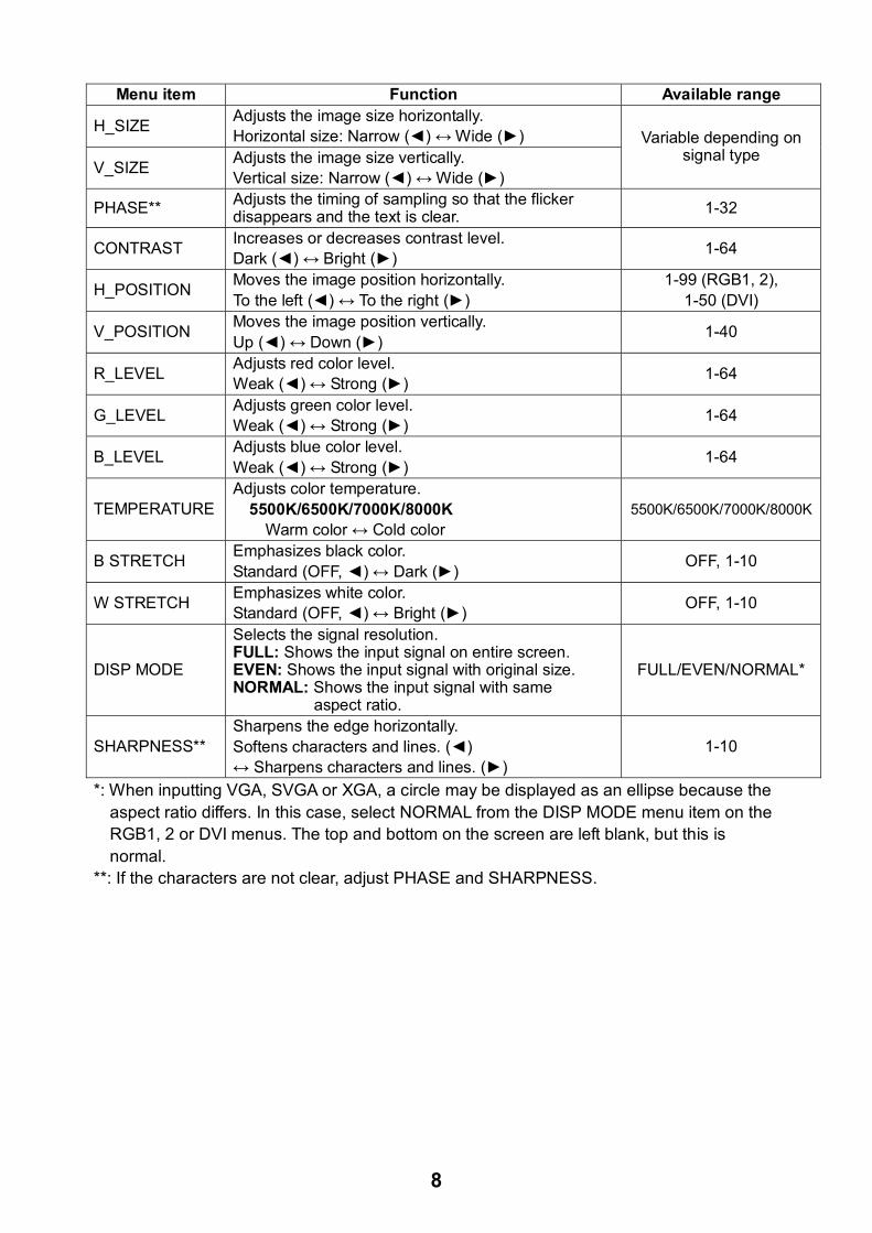
Menu item Function Available range
H_SIZE Adjusts the image size horizontally. Horizontal size: Narrow () ↔ Wide ()
V_SIZE Adjusts the image size vertically. Vertical size: Narrow () ↔ Wide ()
Variable depending on signal type
PHASE** Adjusts the timing of sampling so that the flicker disappears and the text is clear. 1-32
CONTRAST Increases or decreases contrast level. Dark () ↔ Bright () 1-64
H_POSITION Moves the image position horizontally. To the left () ↔ To the right ()
1-99 (RGB1, 2), 1-50 (DVI)
V_POSITION Moves the image position vertically. Up () ↔ Down () 1-40
R_LEVEL Adjusts red color level. Weak () ↔ Strong () 1-64
G_LEVEL Adjusts green color level. Weak () ↔ Strong () 1-64
B_LEVEL Adjusts blue color level. Weak () ↔ Strong () 1-64
TEMPERATURE Adjusts color temperature.
5500K/6500K/7000K/8000K Warm color ↔ Cold color
5500K/6500K/7000K/8000K
B STRETCH Emphasizes black color. Standard (OFF, ) ↔ Dark () OFF, 1-10
W STRETCH Emphasizes white color. Standard (OFF, ) ↔ Bright () OFF, 1-10
DISP MODE
Selects the signal resolution. FULL: Shows the input signal on entire screen. EVEN: Shows the input signal with original size. NORMAL: Shows the input signal with same aspect ratio.
FULL/EVEN/NORMAL*
SHARPNESS** Sharpens the edge horizontally. Softens characters and lines. () ↔ Sharpens characters and lines. ()
1-10
*: When inputting VGA, SVGA or XGA, a circle may be displayed as an ellipse because the aspect ratio differs. In this case, select NORMAL from the DISP MODE menu item on the RGB1, 2 or DVI menus. The top and bottom on the screen are left blank, but this is normal.
**: If the characters are not clear, adjust PHASE and SHARPNESS.

9
3.2 VIDEO Setting VIDEO1, VIDEO2 and VIDEO3 screens can be adjusted independently. The picture-in-picture window for each can be adjusted similarly. Also, the size of the picture-in-picture window can be adjusted at VIDEO1 (2 or 3) setting menu.
Picture-in-picture window
Picture-in-picture window
1. Set to the display currently selected, at the DISP selection window. (See section 4.3.) 2. Press the MENU key to show the main menu. 3. Press the or key to select VIDEO1, VIDEO2 or VIDEO3 as appropriate.
Same items are contained on VIDEO1, VIDEO2 and VIDEO3 setting menus.
VIDEO1 (2 or 3) setting menu
4. Press the or key to select the item to set. 5. Press the or key to adjust. 6. Press the MENU key to close the menu.
Menu item Function Available range
PIP_SIZE Adjusts the size of picture-in-picture window. 1 (35 mm x 27 mm) - 10 (237 mm x 189 mm)
CONTRAST Increases or decreases contrast level. 1-64 R_LEVEL Adjusts red color level. 1-64 G_LEVEL Adjusts green color level. 1-64 B_LEVEL Adjusts blue color level. 1-64 TEMPERATURE Adjusts color temperature. 5500K/6500K/7000K/8000KB STRETCH Emphasizes black color. OFF, 1-10 W STRETCH Emphasizes white color. OFF, 1-10 (Refer to the table on page 8.)
RGB1 RGB2 DVI VIDEO1 VIDEO2 VIDEO3 OSD SYSTEM
PIP_SIZE 5 (1 – 10)CONTRAST 44 (1 – 64) R_LEVEL 31 (1 – 64) G_LEVEL 31 (1 – 64) B_LEVEL 31 (1 – 64) TEMPERATURE 7000K (5500K/6500K/7000K/8000K) B STRETCH OFF (OFF, 1 – 10) W STRETCH OFF (OFF, 1 – 10)

10
3.3 Menu Window Setting 3.3.1 Adjusting the menu window The menu window can be moved and translucentized on the OSD (On Screen Display) menu. 1. Press the MENU key to show the main menu. 2. Press the or key to select OSD.
OSD menu 3. Press the or key to select the item to set. 4. Press the or key to adjust. 5. Press the MENU key to close the menu.
Menu item Function Available range
H_POSITION Moves the menu window horizontally. To the left () ↔ To the right () 1-29
V_POSITION Moves the menu window vertically. Up () ↔ Down () 1-37
TRANSLUCENT
Translucentizes the background color on the menu window. OFF: Blue ON: Translucent
OFF, ON
PIP SW TIME
Switches the screen image on the PIP window among VIDEO1, VIDEO2 and VIDEO3 at the interval (5-20 sec) selected here. OFF: This function is turned off.
OFF, 5-20
PIP SKIP
Chooses which video signals to display in the PIP window when PIP SW TIME is enabled. OFF: VIDEO1, VIDEO2 and VIDEO3 are shown in turn. V1: VIDEO2 and VIDEO3 are shown alternately. V2: VIDEO1 and VIDEO3 are shown alternately. V3: VIDEO1 and VIDEO2 are shown alternately.
OFF, V1/V2/V3
CUSTOM NAME See the next section.
RGB1 RGB2 DVI VIDEO1 VIDEO2 VIDEO3 OSD SYSTEM
H_POSITION 15 (1 – 29)V_POSITION 37 (1 – 37) TRANSLUCENT OFF (OFF/ON) PIP SW TIME OFF (OFF, 5-20) PIP SKIP OFF (OFF, V1/V2/V3) CUSTOM NAME RGB1 = RGB1______ RGB2 = RGB2______ DVI = DVI_______ VIDEO1 = VIDEO1____ VIDEO2 = VIDEO2____ VIDEO3 = VIDEO3____
11
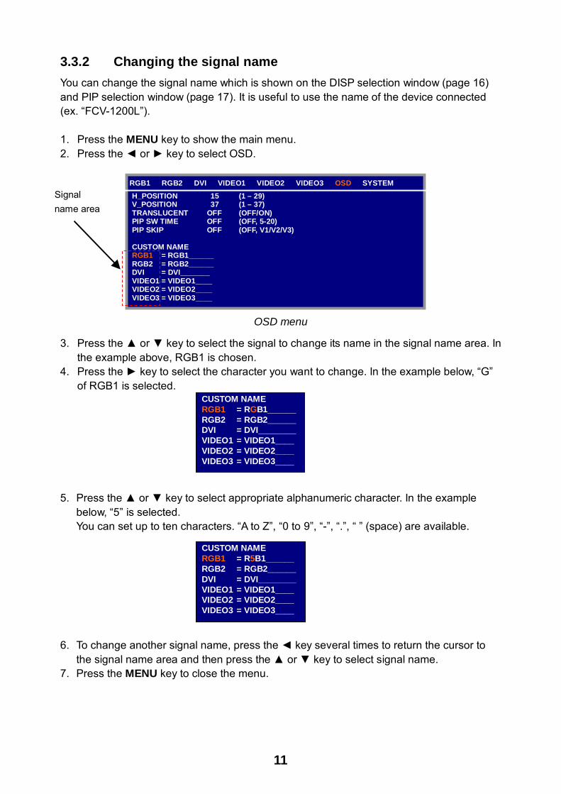
3.3.2 Changing the signal name You can change the signal name which is shown on the DISP selection window (page 16) and PIP selection window (page 17). It is useful to use the name of the device connected (ex. “FCV-1200L”). 1. Press the MENU key to show the main menu. 2. Press the or key to select OSD.
OSD menu
3. Press the or key to select the signal to change its name in the signal name area. In the example above, RGB1 is chosen.
4. Press the key to select the character you want to change. In the example below, “G” of RGB1 is selected.
5. Press the or key to select appropriate alphanumeric character. In the example
below, “5” is selected. You can set up to ten characters. “A to Z”, “0 to 9”, “-”, “.”, “ ” (space) are available.
6. To change another signal name, press the key several times to return the cursor to
the signal name area and then press the or key to select signal name. 7. Press the MENU key to close the menu.
CUSTOM NAME RGB1 = RGB1______ RGB2 = RGB2______DVI = DVI________ VIDEO1 = VIDEO1____VIDEO2 = VIDEO2____VIDEO3 = VIDEO3____
RGB1 RGB2 DVI VIDEO1 VIDEO2 VIDEO3 OSD SYSTEM H_POSITION 15 (1 – 29)V_POSITION 37 (1 – 37) TRANSLUCENT OFF (OFF/ON) PIP SW TIME OFF (OFF, 5-20) PIP SKIP OFF (OFF, V1/V2/V3) CUSTOM NAME RGB1 = RGB1______ RGB2 = RGB2______ DVI = DVI_______ VIDEO1 = VIDEO1____ VIDEO2 = VIDEO2____ VIDEO3 = VIDEO3____
CUSTOM NAME RGB1 = R5B1______ RGB2 = RGB2______DVI = DVI________ VIDEO1 = VIDEO1____VIDEO2 = VIDEO2____VIDEO3 = VIDEO3____
Signal name area

12
Display unit ID
3.4 Remote Controller Setting A remote controller can be set to be operative with a specific display unit, in the case of multiple MU-170C display units. It is useful to label the display unit and the corresponding remote controller with same name. 1. Press the MENU key to show the main menu. 2. Press the key to select SYSTEM.
SYSTEM menu
3. Press the key to select INFRARED REMOTE. You may set the ID (identification code) of display unit and remote controller. There are four codes in the ID; A, B, C and D.
4. Point the remote controller toward the optical sensor of the display unit, and press any key on the remote controller. The current setting of the remote controller is shown inside the remote controller ID square.
5. Press the RGB2 and BRILL + keys together on the remote controller to change the remote controller ID. With each press of those keys, the remote controller ID switches from A to D in turn and returns to A. Your selection appears inside the square.
6. Press the or key to select the display unit ID so that it is the same as the remote controller ID.
7. Press the MENU key to close the menu.
Remote controller ID square
RGB1 RGB2 DVI VIDEO1 VIDEO2 VIDEO3 OSD SYSTEM INFRARED REMOTE A EXT BRILL CTRL OFF (OFF/ON) DEFAULT RESET NO INFORMATION RGB1 : 1280x1024 fH: 80KHz fV: 75Hz RGB2 : 640x480 fH: 31KHz fV: 60Hz DVI : NO SIGNAL VIDEO1: NTSC VIDEO2: PAL VIDEO3: NO SIGNAL PROGRAM NO.: *****
13
4. OPERATION
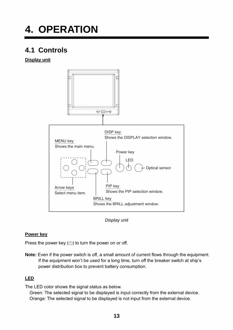
4.1 Controls Display unit
Arrow keysSelect menu item.
DISP keyShows the DISPLAY selection window.
MENU keyShows the main menu.
BRILL keyShows the BRILL adjustment window.
PIP keyShows the PIP selection window.
Power key
LED
Optical sensor
Display unit
Power key
Press the power key ( ) to turn the power on or off. Note: Even if the power switch is off, a small amount of current flows through the equipment.
If the equipment won’t be used for a long time, turn off the breaker switch at ship’s power distribution box to prevent battery consumption.
LED
The LED color shows the signal status as below. Green: The selected signal to be displayed is input correctly from the external device. Orange: The selected signal to be displayed is not input from the external device.

14
Remote controller
VIDEO2VIDEO1
BRILL +
RGB1 RGB2
MENU
VIDEO3
DVI
PIP1 PIP2 PIP3
Remote controller
Key name Function RGB1* Shows the RGB1 signal. RGB2* Shows the RGB2 signal. DVI* Shows the DVI signal. VIDEO1** Shows the VIDEO1 signal on the entire screen. VIDEO2** Shows the VIDEO2 signal on the entire screen. VIDEO3** Shows the VIDEO3 signal on the entire screen. PIP1*** Shows the VIDEO1 signal in the picture-in-picture window. PIP2*** Shows the VIDEO2 signal in the picture-in-picture window. PIP3*** Shows the VIDEO3 signal in the picture-in-picture window. BRILL (-) Decreases the display brilliance. BRILL (+) Increases the display brilliance. MENU Shows the main menu. Arrow keys Select the menu items.
*: PIP window remains on the RGB1, RGB2 or DVI screen. **: When the previous selection is PIP1, PIP2 or PIP 3, the PIP window may be erased
by pressing these keys. ***: When the previous selection is VIDEO1 (2 or 3) or the setting value on the PIP SW
TIME is from 5 to 20, these keys are inoperative. Also, pressing these keys turns the PIP window on and off alternately.
For PIP (picture-in-picture), see “3.2 VIDEO Setting”.
15
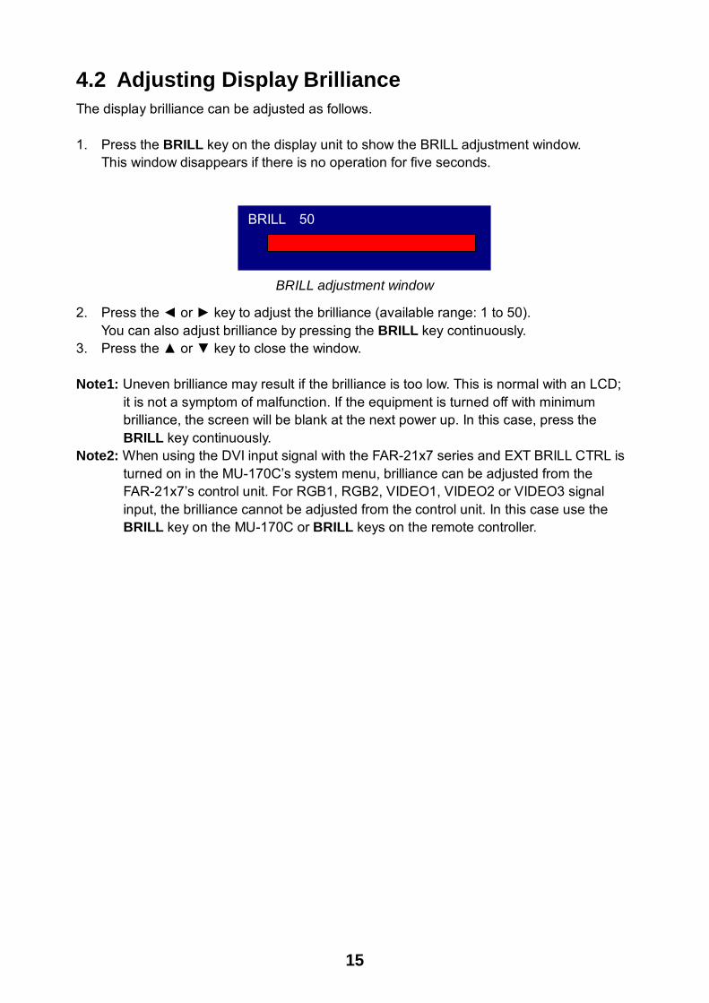
4.2 Adjusting Display Brilliance The display brilliance can be adjusted as follows. 1. Press the BRILL key on the display unit to show the BRILL adjustment window.
This window disappears if there is no operation for five seconds.
BRILL adjustment window
2. Press the or key to adjust the brilliance (available range: 1 to 50). You can also adjust brilliance by pressing the BRILL key continuously.
3. Press the or key to close the window.
Note1: Uneven brilliance may result if the brilliance is too low. This is normal with an LCD; it is not a symptom of malfunction. If the equipment is turned off with minimum brilliance, the screen will be blank at the next power up. In this case, press the BRILL key continuously.
Note2: When using the DVI input signal with the FAR-21x7 series and EXT BRILL CTRL is turned on in the MU-170C’s system menu, brilliance can be adjusted from the FAR-21x7’s control unit. For RGB1, RGB2, VIDEO1, VIDEO2 or VIDEO3 signal input, the brilliance cannot be adjusted from the control unit. In this case use the BRILL key on the MU-170C or BRILL keys on the remote controller.
BRILL 50

16
4.3 Choosing Source for Main Picture Choose the signal to display on the entire screen as follows: 1. Press the DISP key to show the DISP selection window.
This window disappears if there is no operation for five seconds.
DISP selection window
2. Press the or key to select a signal. You can also select the signal by pressing the DISP key continuously. RGB1-2: The signal from the chosen RGB port is displayed. DVI: The signal from the DVI port is displayed. VIDEO1-3: The external video from the chosen VIDEO port is displayed on the entire screen.
3. Press the or key to close the window. The window disappears if there is no operation within five seconds.
Note: The name of the selected signal appears at the right top corner for five seconds after
the DISP selection window is erased.
RGB1 RGB2 DVI VIDEO1 VIDEO2 VIDEO3

17
4.4 Choosing Source for Picture-in-Picture Choose the source for the picture-in-picture window as follows: Note1: The screen image on the picture-in-picture window can be switched automatically
among VIDEO1, VIDEO2 and VIDEO3 at the interval specified. Set the PIP SW TIME on the OSD menu. For details, see “3.3.1 Adjusting the menu window”.
Note2: The size of the picture-in-picture window can be adjusted on the VIDEO1, 2 and 3 menus. For details, see “3.2 VIDEO Setting”.
1. With the RGB1, RGB2 or DVI display shown, press the PIP key.
The PIP selection window appears. This window disappears if there is no operation for five seconds.
PIP selection window
2. Press the or key to select the VIDEO port desired. VIDEO can also be selected by pressing the PIP key continuously. To turn off the picture-in-picture window, choose OFF.
3. Press the or key to close the window. Note: The picture-in-picture window can be moved by pressing the arrow keys when menu
windows are closed.
VIDEO1VIDEO2 VIDEO3 OFF

18
5. MAINTENANCE, TROUBLESHOOTING
WARNINGELECTRICAL SHOCK HAZARDDo not open the equipment.
Only qualified personnelshould work inside theequipment.
5.1 Maintenance Routine maintenance Regular maintenance is important for good performance. Check the following on a regular basis to keep the equipment in good operating condition.
• Check that the connectors at the bottom of the display unit are tightly fastened.
• Check the ground wire and ground terminal for rust. Clean if necessary. Confirm that the ground wire is tightly fastened.
• Remove dust and dirt from the display unit and LCD with a dry, soft cloth. Do not use chemical cleaners to clean any part of the display unit – they can remove paint and markings.
• Wipe the LCD carefully to prevent scratching, using tissue paper and an LCD cleaner. To remove dirt or salt deposits, use an LCD cleaner, wiping slowly with tissue paper so as to dissolve the dirt or salt. Change paper frequently so the salt or dirt will not scratch the LCD. Do not use solvents such as thinner, acetone or benzene for cleaning.
• Clean the filter at the intake vent regularly. To remove the filter, grasp the intake vent with fingers and pull forward. Use an air blower to remove dust and dirt from the filter. If it is particularly dirty, wash it in water or mild detergent and then let it dry. When reattaching the filter, be sure the filters are correctly set to the holes for the intake vent.
Intake vent
Display unit, rear view

19
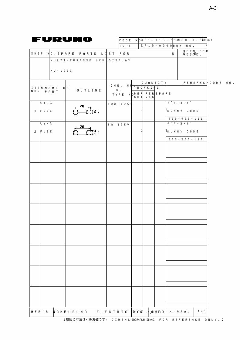
Fuse replacement The fuse in the fuse holder protects the equipment from internal fault. If the fuse blows, find the cause before replacing it. If the fuse blows again after replacement, request service.
Ship’s power source Rating of fuse
12 VDC 10 A
24 VDC 5 A
Battery replacement The remote controller has two AA batteries. If the distance from which the remote controller can be operated has decreased, change the batteries. Note: Use the two AA batteries. Replace
all batteries together. Do not mix old and new batteries.
LCD replacement The life of the LCD is about 40,000 hours. When the brilliance cannot be raised sufficiently, replace the LCD.
5.2 Troubleshooting The table below provides troubleshooting procedures to use when no picture appears. If you cannot restore the picture, do not attempt to check inside the equipment – there are no user serviceable parts inside. Refer any work to a qualified technician.
Troubleshooting table
Reason for no picture Remedy
Ship’s battery voltage too high. Check battery voltage.
Fuse has blown. Replace fuse.
Cable between MU-170C and external equipment has loosened.
Refasten cable. You can confirm which signals are currently input in the SYSTEM menu (see the figure on the next page).
Power cable has loosened from the terminal board.
Refasten cable.
WARNINGUse the proper fuse.
Use of a wrong fuse can cause fire ordamage to the equipment.
WARNINGEnsure battery polarity is correct.
Wrong polarity may cause the batteriesto explode.
Dispose of used batteries as industrialwaste. Follow the appropriate regulationsfor the disposal of industrial waste.

20
5.3 Clearing the Memory You may want to clear the memory to start afresh with default settings. You can do this as follows: 1. Press the MENU key to show the main menu. 2. Press the key to open the SYSTEM menu. 3. Select DEFAULT RESET by arrow keys. 4. Press the key to select YES.
SYSTEM menu
5. Press the key again to select “reset”. 6. Press the MENU key to close the menu.
RGB1 RGB2 DVI VIDEO1 VIDEO2 VIDEO3 OSD SYSTEM INFRARED REMOTE A AEXT BRILL CTRL OFF (OFF/ON) DEFAULT RESET YES All custom settings will be lost. ←key: cancel →key: reset INFORMATION RGB1 : 1280x1024 fH: 80KHz fV: 75Hz RGB2 : 640x480 fH: 31KHz fV: 60Hz DVI : NO SIGNAL VIDEO1: NTSC VIDEO2: PAL VIDEO3: NO SIGNAL PROGRAM NO. : *****

FURUNO MU-170C
SP - 1 E2034S01B
SPECIFICATIONS OF MULTI-PURPOSE LCD DISPLAY MU-170C
1 GENERAL 1.1 Display 17-inch SXGA color TFT-LCD, 338 x 270 mm
1.2 Brightness maximum: 1000 cd/m2 , minimum: 2 cd/m2 or less
1.3 Resolution 1280 x 1024 (SXGA)
1.4 Viewing Angle up/down: 75°, left/right: 80°
1.5 Input Signal
RGB ports 2 ports, VESA (VGA, SVGA, XGA, SXGA),
(0.7 Vp-p, Synchronization: TTL level)
DVI port 1 port, VESA (VGA, SVGA, XGA, SXGA)
VIDEO ports 3 ports, NTSC/PAL, 0.7 Vp-p (75 Ω)
2 POWER SUPPLY 12-24 VDC: 6.0-3.0 A
3 ENVIRONMENTAL CONDITION 3.1 Ambient Temperature
Display Unit -15°C to +55°C
Remote Controller +5°C to +35°C
3.2 Relative Humidity 93% at +40°C
3.3 Waterproofing (IEC60529)
Display Unit Front panel: IP56, CFR46, Rear panel: IP20
Remote Controller IPX0
3.4 Vibration 2-5 Hz and up to 13.2 Hz with an excursion of ±1 mm ±10 %
(IEC 60945 ed.4) (7 m/s2 maximum acceleration at 13.2 Hz)
13.2-100 Hz with a constant maximum acceleration of 7 m/s2
4 COATING COLOR N3.0 (Not changed)

FURUNO ELECTRIC CO., LTD.9-52 Ashihara-Cho, Nishinomiya City, 662-8580, Hyogo, JapanTel: +81 798-65-2111 Fax: +81 798-65-4200
Pub NO. DOC-853
EC Declaration of Conformity
We FURUNO ELECTRIC CO., LTD.-----------------------------------------------------------------------------------------------------------------------
(Manufacturer)
9-52 Ashihara-Cho, Nishinomiya City, 662-8580, Hyogo, Japan-----------------------------------------------------------------------------------------------------------------------
(Address)
declare under our sole responsibility that the product
Multi-purpose LCD display Type MU-170C-----------------------------------------------------------------------------------------------------------------------
(Model name, serial number)
to which this declaration relates is in conformity with the following standard(s) or other normativedocument(s)
EN 60945: 1997-01 (IEC 60945 Third edition: 1996-11) – Clauses 10.2 and 10.3IEC 60945 Fourth edition: 2002-08 – Clauses 9.2, 9.3, 10.3, 10.4, 10.5, 10.8 and 10.9-----------------------------------------------------------------------------------------------------------------------
(title and/or number and date of issue of the standard(s) or other normative document(s))
For assessment, see
• EMC Test Report FLI 12-05-052 of 25 November 2005 prepared by Furuno LabotechInternational Co., Ltd.
This declaration is issued according to the Council Directive of 3 May 1989 on the approximation ofthe laws of the Member States relating to electromagnetic compatibility (89/336/EEC).
Nishinomiya City, JapanNovember 25, 2005----------------------------------------------
(Place and date of issue)
On behalf of Furuno Electric Co., Ltd.
Hiroaki KomatsuManager,International Rules and Regulations------------------------------------------------------------------
(name and signature or equivalent marking of authorized person)

NAME
OUTLINE
Q'TY
DESCRIPTION/CODE
PA
CK
IN
G
LI
ST
19AX-X-9851-3
MU-170C
1/1
NAME
OUTLINE
Q'TY
DESCRIPTION/CODE
ユニ
ット
UNIT
LCD表示
器
MULTI-PURPOSE LCD
DISPLAY
MU-1
70C
000-
012
-653
1
リモコンセット
REMOTE CONTROLLER SET
RMC-
200
リモコンキーユニット
REMOTE CONTROLLER
RMC-
200
000-
149
-069
1
リモコンビニールケース
VINYL CASE FOR REMOTE
CONTROLLER
14-0
34-
2075-
1
100-
292
-801
1
リモコンハリマーク
STICKER
19-0
24-
1313-
0
100-
315
-270
1
電池
セット (単3X2)
SIZE AA BATTERY
999-
999
-113
1 (*)
予備
品SPARE PARTS
SP19
-0040
1
予備
品
SPARE PARTS
SP19
-00
401
001-
416
-700
1
付属
品ACCESSORIES
FP19
-0100
1
付属
品
ACCESSORIES
FP19
-01
001
001-
416
-740
1
工事
材料
INSTALLATION MATERIALS
CP19-00500
電源
ケーブル
POWER CABLE
14AW
G-2
C-PVC
*5M*
000-
154
-337
1
図書
DOCUMENT
フラッシュマウント型
紙
FLUSH MOUNTING TEMPLATE
C22-
005
03-*
000-
156
-775
1
取扱
説明
書
OPERATOR'S MANUAL
OMC-
203
40-*
000-
153
-885
1
ヒューズ変更
願い
NOTICE FOR FUSE
REPLACEMENT
C22-
005
01-*
000-
154
-137
1
(*)は
、ダミ
ーコー
ドに
付き
、注
文で
きま
せん
。
(*)
TH
IS C
OD
E C
AN
NO
T B
E O
RD
ER
ED
.
(略
図の
寸法
は、
参考値
です
。 DIMENSIONS IN DRAWING FOR REFERENCE ONLY.)
19AX-X-9851

CODE NO. 001-416-740
TYPE FP19-01001
略 図
OUTLINE
名 称
NAME
数量
Q'TY用途/備考
REMARKS
番 号
NO.
型名/規格
DESCRIPTIONS
1/1
-0
ACCESSORIES
付属品表
19AX-X-9501
MULTI-PURPOSE LCD DISPLAY
MU-170C
+トラスタッピンネジ
SELF-TAPPING SCREW
5X40 SUS304
4
000-150-749
1
CODE NO.
(略図の寸法は、参考値です。 DIMENSIONS IN DRAWING FOR REFERENCE ONLY.)
FURUNO ELECTRIC CO .,LTD.
19AX-X-9501
CODE NO. 001-416-700
TYPE SP19-00401
ITEM NO.
NAME OF PART OUTLINE
DWG. NO.
OR
TYPE NO. PERSET
PERVES
SPARE
WORKING
QUANTITY REMARKS/CODE NO.
BOX NO. P
SHIP NO. SPARE PARTS LIST FOR U S ESETS PER VESSEL
-019AX-X-9301 1/1
MULTI-PURPOSE LCD DISPLAY
MU-170C
ヒューズ 10A 125V
1 3
ダミーコード
DUMMY CODEFUSE
999-999-111
1
ヒューズ 5A 125V
1 3
ダミーコード
DUMMY CODEFUSE
999-999-112
2
1/1MFR'S NAME FURUNO ELECTRIC CO.,LTD. DWG NO.
(略図の寸法は、参考値です。 DIMENSIONS IN DRAWING FOR REFERENCE ONLY.)
19AX-X-9301


24
3
A
1
B C
DRAWN
CHECKED
APPROVED
DWG.No.
TITLE
NAME
名称
E.MIYOSHI
TAKAHASHI.T
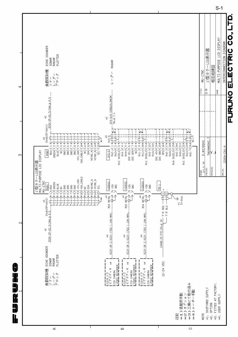
17型カラーLCD表示器
MU-170C
C2034-C01-A
INTERCONNECTIONDIAGRAM
MULTI-PURPOSELCDDISPLAY
相互結線図
MULTI-PURPOSELCDDISPLAY
ソナー
レーダー
プロッタ
魚群探知機ECHOSOUNDER
SONAR
RADAR
PLOTTER
NCGND
BLUE
GREEN
RED
GND
GND
NC GND
11 15141312101 2 3 4 6 7 8 95
17型カラーLCD表示器
RGB1
*2
GND
GND
*4*4
RCAMETAL
*4*4
RCAMETAL
GND
*4*4
RCAMETAL
VIDEO1
VIDEO2
VIDEO3
NCGND
GNDGNDGNDNC
ソナー
レーダー
プロッタ
魚群探知機ECHOSOUNDER
SONAR
RADAR
PLOTTER
987 12 13 14 1511106541 2 3 1 2 3
DVI-D/DSINGLELINK5M
5m,φ7.1
*2DVI-D
RGB2
*23COX-2P-6C,5/10m,φ8.5
P
DVI-D*3
2112-24VDC
+ -RED
BLU
アカアオ
14AWG-2C-PVC,5m,φ10
TB-1
MU-170C
レーダーRADAR
NOTE
注記
3C2VOR2.5C2V(75Ω),10mMAX.
3C2VOR2.5C2V(75Ω),10mMAX.
*4CCDCAMERA
ビデオデッキ
CCDカメラ
*4CCDCAMERA
ビデオデッキ
CCDカメラ
3C2VOR2.5C2V(75Ω),10mMAX.
*4CCDCAMERA
ビデオデッキ
CCDカメラ
*3*3
Dsub15P(mini)
Dsub15P(mini)
3COX-2P-6C,5/10m,φ8.5
IV-8sq.
*1*1)造船所手配
*2)オプション
*3)工場にて取付済み
*4)ユーザー手配
*1.SHIPYARDSUPPLY
*2.OPTION
*4.USERSUPPLY
VIDEORECORDER
VIDEORECORDER
VIDEORECORDER
VIN
VIN
VIN
RED
GREEN
BLUE
+5V_VGA
+5V_VGA
SDA
SDA
SCL
SCL
1514 1716 1918P
NC
10 116 7 8 9P
2422 23P
4 5 12 13 20 21
Rx2-Rx2+
Rx2SHIELDRx4-Rx4+
DDCSCL
DDCSDA
Rx1-Rx1+
Rx1SHIELDRx3-Rx3+
DDC+5V
DDCGNDHPD
RxO-RxO+
Rx5-Rx5+
RxCSHIELDRxC+RxC-
*3.FITTEDATFACTORY.
VGA_CABLE
VGA_CABLE
HSYNC_N
VSYNC_N
HSYNC_N
VSYNC_N
Rx0SHIELD
Oct.5,'05