one-step large-scale deposition of salt-free dna origami ... · one-step large-scale deposition of...
TRANSCRIPT
This is an electronic reprint of the original article.This reprint may differ from the original in pagination and typographic detail.
Powered by TCPDF (www.tcpdf.org)
This material is protected by copyright and other intellectual property rights, and duplication or sale of all or part of any of the repository collections is not permitted, except that material may be duplicated by you for your research use or educational purposes in electronic or print form. You must obtain permission for any other use. Electronic or print copies may not be offered, whether for sale or otherwise to anyone who is not an authorised user.
Linko, Veikko; Shen, B.; Tapio, Kosti; Toppari, J.J.; Kostiainen, Mauri; Tuukkanen, Sampo
One-Step Large-Scale Deposition of Purified and Salt-Free DNA OrigamiNanostructures
Published in:SCIENTIFIC REPORTS
DOI:10.1038/srep15634
Published: 23/10/2015
Document VersionPublisher's PDF, also known as Version of record
Please cite the original version:Linko, V., Shen, B., Tapio, K., Toppari, J. J., Kostiainen, M., & Tuukkanen, S. (2015). One-Step Large-ScaleDeposition of Purified and Salt-Free DNA Origami Nanostructures. SCIENTIFIC REPORTS, 5, 1-8. [15634].DOI: 10.1038/srep15634

1Scientific RepoRts | 5:15634 | DOi: 10.1038/srep15634
www.nature.com/scientificreports
One-step large-scale deposition of salt-free DNA origami nanostructuresVeikko Linko1, Boxuan Shen2, Kosti Tapio2, J. Jussi Toppari2, Mauri A. Kostiainen1 & Sampo Tuukkanen3
DNA origami nanostructures have tremendous potential to serve as versatile platforms in self-assembly -based nanofabrication and in highly parallel nanoscale patterning. However, uniform deposition and reliable anchoring of DNA nanostructures often requires specific conditions, such as pre-treatment of the chosen substrate or a fine-tuned salt concentration for the deposition buffer. In addition, currently available deposition techniques are suitable merely for small scales. In this article, we exploit a spray-coating technique in order to resolve the aforementioned issues in the deposition of different 2D and 3D DNA origami nanostructures. We show that purified DNA origamis can be controllably deposited on silicon and glass substrates by the proposed method. The results are verified using either atomic force microscopy or fluorescence microscopy depending on the shape of the DNA origami. DNA origamis are successfully deposited onto untreated substrates with surface coverage of about 4 objects/mm2. Further, the DNA nanostructures maintain their shape even if the salt residues are removed from the DNA origami fabrication buffer after the folding procedure. We believe that the presented one-step spray-coating method will find use in various fields of material sciences, especially in the development of DNA biochips and in the fabrication of metamaterials and plasmonic devices through DNA metallisation.
DNA has astonishing potential as programmable nanoscale construction material for the bottom-up-based nanofabrication1 and for a great variety of bionanotechnological applications2. To date, a plethora of design strategies for assembling DNA molecules into customized structures and templates have been introduced2. Arguably, one of the most elegant one is a scaffolded DNA origami technique, which enables a straightforward fabrication of arbitrary two- (2D)3 and three-dimensional (3D)4,5 nanoshapes, meshed structures6 as well as large assemblies with high spatial addressability7.
Recently, DNA nanoarchitectures have been utilized in various innovative applications that truly underline the feasibility of the structural DNA nanotechnology. DNA origamis can serve as molecu-lar scale circuit boards in nanoelectronics8, scaffolds for plasmonic structures9,10 and gatekeepers for solid-state nanopores11,12. Biotechnological examples include smart molecular devices13,14 such as nano-robots15, cellular delivery vehicles16,17, and synthetic ion channels18.
Despite the fact that DNA origami itself has limited properties in optics and in electronics19–22, its use in templating is extremely promising. There exist plenty of placement and deposition methods for DNA origamis that are useful for patterning on different substrates. One straightforward way is to utilize chemically modified surfaces, which enable selective anchoring of the origamis23–25, whereas some sub-strates can be used to assist large-scale lattice formation of DNA origamis26–28. In addition, hierarchically
1Aalto University, Department of Biotechnology and Chemical Technology, Biohybrid Materials, Espoo, P.O. Box 16100, FI-00076 Aalto, Finland. 2University of Jyvaskyla, Department of Physics, Nanoscience Center, Jyväskylä, P.O. Box 35, FI-40014 University of Jyväskylä, Finland. 3Tampere University of Technology, Department of Automation Science and Engineering, Tampere, P.O. Box 692, FI-33101, Finland. Correspondence and requests for materials should be addressed to M.A.K. (email: [email protected]) or S.T. (email: [email protected])
received: 19 June 2015
Accepted: 28 September 2015
Published: 23 October 2015
OPEN
www.nature.com/scientificreports/
2Scientific RepoRts | 5:15634 | DOi: 10.1038/srep15634
ordered nanosystems can be obtained by combining DNA structures with patterned substrates, such as lithographically fabricated confined wells29,30 and other surface patterns, which are specifically designed for the alignment of DNA structures31,32. Moreover, single DNA molecules33–35 and complex DNA nano-architectures36–38 can be selectively guided and anchored onto substrates by means of electric fields. Nevertheless, in order to utilize such approaches one has to pay extra attention to the deposition con-ditions (salt concentration, pH, surface chemistry etc.). In many occasions, the required treatments and prevalent conditions set strict limitations to the conceivable applications.
In general, print-coating technologies provide high-throughput and low-cost patterning methods for solution processable materials39. Although aqueous dispersion of DNA is solution processable, these techniques have not been so far adapted in the field of structural DNA nanotechnology. However, in this article we show that the high spatial addressability of the structurally different DNA origamis can be gen-uinely combined with the large-scale print-coating methods. The authors have previously demonstrated the feasibility of the solution processing techniques in various other applications, such as stretchable electrodes40, piezoelectric sensors41,42, transparent touch panels43, supercapacitors44,45 and energy harvest-ers46,47. The same methods are now expanded to the field of DNA nanotechnology.
In this study a spray-coating technique is used to achieve a straightforward, fast and cost-effective way to pattern substrates with custom-shaped DNA structures on large scale (Fig. 1). The deposition areas demonstrated here are ~10 cm2, but the method can be easily scaled-up to wafer-scales and even larger surfaces. The proposed method does not require special substrate conditions or washing procedures, and moreover, salt residues from the DNA origami buffer can be eliminated by removing salt ions right before the coating procedure. With this method, the fabricated DNA origami dispersions can be utilised fully without any loss of material, which makes the relative cost of DNA reagents negligible. Thus, this highly robust technique could find use in many applications. Homogeneous large-scale DNA patterns could be exploited e.g. in creating DNA origami microarrays48, whereas DNA origami-based metallic assemblies49 can yield intriguing opportunities for developing nanoplasmonics10,50 and metamaterials51.
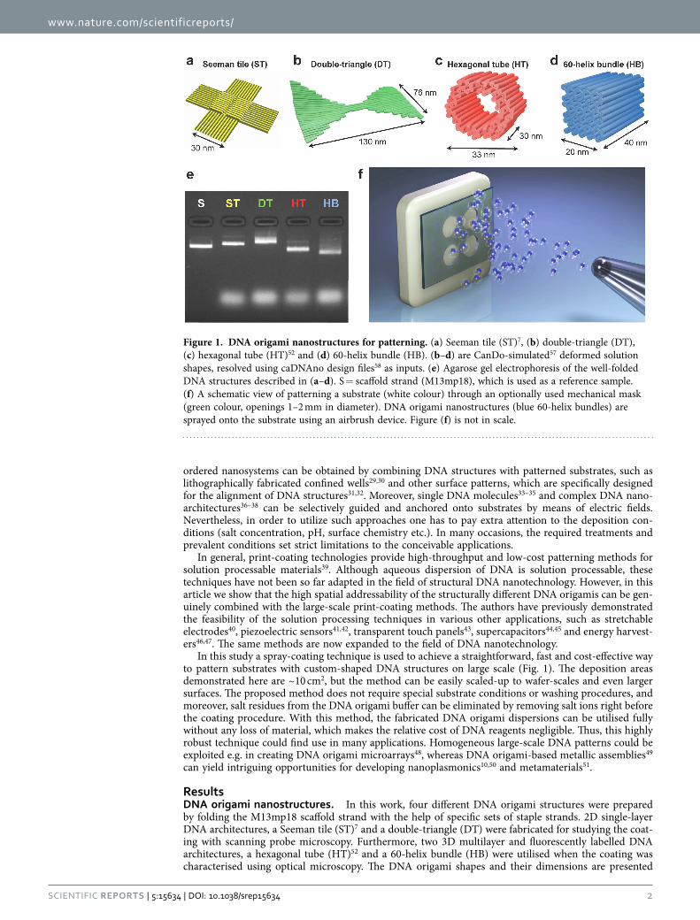
ResultsDNA origami nanostructures. In this work, four different DNA origami structures were prepared by folding the M13mp18 scaffold strand with the help of specific sets of staple strands. 2D single-layer DNA architectures, a Seeman tile (ST)7 and a double-triangle (DT) were fabricated for studying the coat-ing with scanning probe microscopy. Furthermore, two 3D multilayer and fluorescently labelled DNA architectures, a hexagonal tube (HT)52 and a 60-helix bundle (HB) were utilised when the coating was characterised using optical microscopy. The DNA origami shapes and their dimensions are presented
Figure 1. DNA origami nanostructures for patterning. (a) Seeman tile (ST)7, (b) double-triangle (DT), (c) hexagonal tube (HT)52 and (d) 60-helix bundle (HB). (b–d) are CanDo-simulated57 deformed solution shapes, resolved using caDNAno design files58 as inputs. (e) Agarose gel electrophoresis of the well-folded DNA structures described in (a–d). S = scaffold strand (M13mp18), which is used as a reference sample. (f) A schematic view of patterning a substrate (white colour) through an optionally used mechanical mask (green colour, openings 1–2 mm in diameter). DNA origami nanostructures (blue 60-helix bundles) are sprayed onto the substrate using an airbrush device. Figure (f) is not in scale.
www.nature.com/scientificreports/
3Scientific RepoRts | 5:15634 | DOi: 10.1038/srep15634
in Fig. 1a–d. The correct folding of all four DNA objects was verified using agarose gel elecrophoresis (Fig. 1e) by comparing the running speed of the leading bands to the reference sample (M13mp18 scaf-fold). In addition, correct HT and HB folding was confirmed using transmission electron microscopy (Supplementary Fig. S1 and Supplementary Note 2).
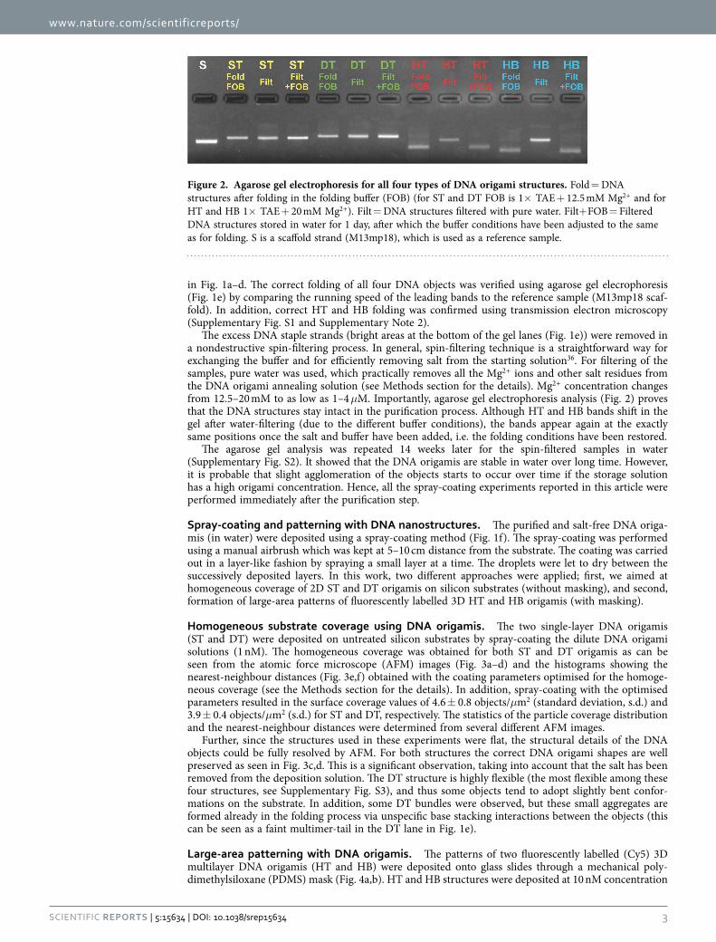
The excess DNA staple strands (bright areas at the bottom of the gel lanes (Fig. 1e)) were removed in a nondestructive spin-filtering process. In general, spin-filtering technique is a straightforward way for exchanging the buffer and for efficiently removing salt from the starting solution36. For filtering of the samples, pure water was used, which practically removes all the Mg2 + ions and other salt residues from the DNA origami annealing solution (see Methods section for the details). Mg2 + concentration changes from 12.5–20 mM to as low as 1–4 μM. Importantly, agarose gel electrophoresis analysis (Fig. 2) proves that the DNA structures stay intact in the purification process. Although HT and HB bands shift in the gel after water-filtering (due to the different buffer conditions), the bands appear again at the exactly same positions once the salt and buffer have been added, i.e. the folding conditions have been restored.
The agarose gel analysis was repeated 14 weeks later for the spin-filtered samples in water (Supplementary Fig. S2). It showed that the DNA origamis are stable in water over long time. However, it is probable that slight agglomeration of the objects starts to occur over time if the storage solution has a high origami concentration. Hence, all the spray-coating experiments reported in this article were performed immediately after the purification step.
Spray-coating and patterning with DNA nanostructures. The purified and salt-free DNA origa-mis (in water) were deposited using a spray-coating method (Fig. 1f). The spray-coating was performed using a manual airbrush which was kept at 5–10 cm distance from the substrate. The coating was carried out in a layer-like fashion by spraying a small layer at a time. The droplets were let to dry between the successively deposited layers. In this work, two different approaches were applied; first, we aimed at homogeneous coverage of 2D ST and DT origamis on silicon substrates (without masking), and second, formation of large-area patterns of fluorescently labelled 3D HT and HB origamis (with masking).
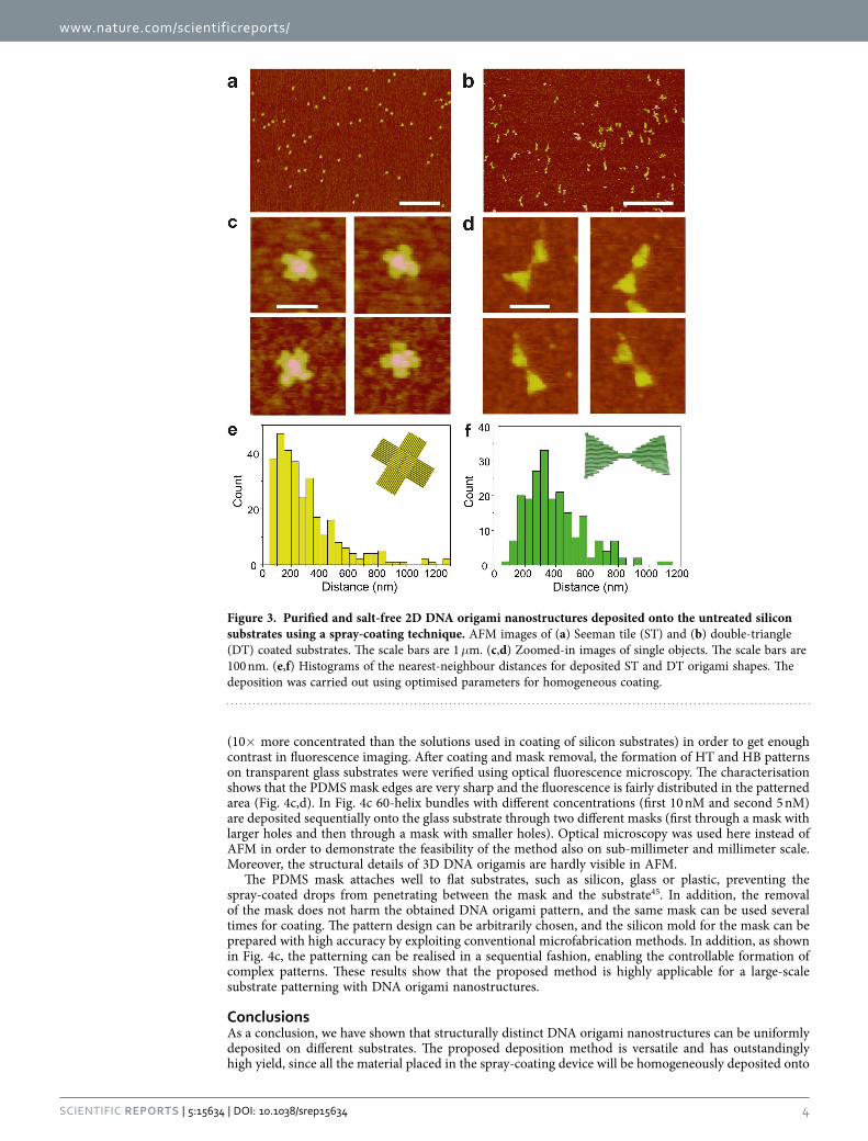
Homogeneous substrate coverage using DNA origamis. The two single-layer DNA origamis (ST and DT) were deposited on untreated silicon substrates by spray-coating the dilute DNA origami solutions (1 nM). The homogeneous coverage was obtained for both ST and DT origamis as can be seen from the atomic force microscope (AFM) images (Fig. 3a–d) and the histograms showing the nearest-neighbour distances (Fig. 3e,f) obtained with the coating parameters optimised for the homoge-neous coverage (see the Methods section for the details). In addition, spray-coating with the optimised parameters resulted in the surface coverage values of 4.6 ± 0.8 objects/μm2 (standard deviation, s.d.) and 3.9 ± 0.4 objects/μm2 (s.d.) for ST and DT, respectively. The statistics of the particle coverage distribution and the nearest-neighbour distances were determined from several different AFM images.
Further, since the structures used in these experiments were flat, the structural details of the DNA objects could be fully resolved by AFM. For both structures the correct DNA origami shapes are well preserved as seen in Fig. 3c,d. This is a significant observation, taking into account that the salt has been removed from the deposition solution. The DT structure is highly flexible (the most flexible among these four structures, see Supplementary Fig. S3), and thus some objects tend to adopt slightly bent confor-mations on the substrate. In addition, some DT bundles were observed, but these small aggregates are formed already in the folding process via unspecific base stacking interactions between the objects (this can be seen as a faint multimer-tail in the DT lane in Fig. 1e).
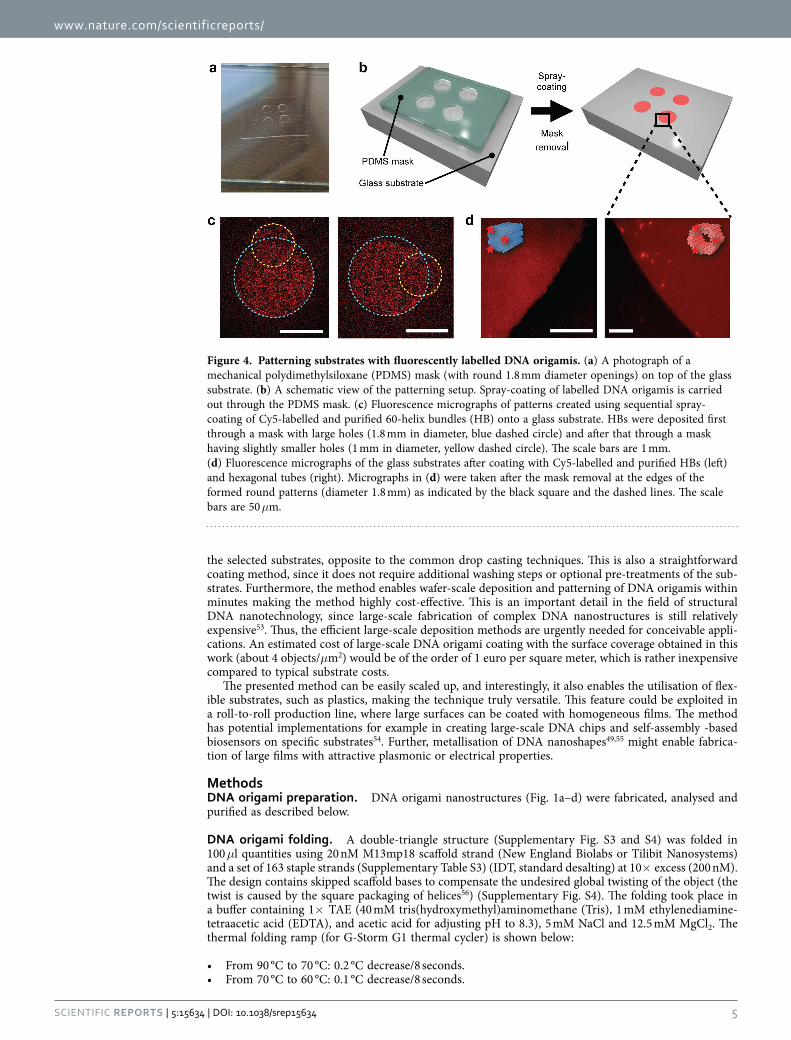
Large-area patterning with DNA origamis. The patterns of two fluorescently labelled (Cy5) 3D multilayer DNA origamis (HT and HB) were deposited onto glass slides through a mechanical poly-dimethylsiloxane (PDMS) mask (Fig. 4a,b). HT and HB structures were deposited at 10 nM concentration
Figure 2. Agarose gel electrophoresis for all four types of DNA origami structures. Fold = DNA structures after folding in the folding buffer (FOB) (for ST and DT FOB is 1× TAE + 12.5 mM Mg2 + and for HT and HB 1× TAE + 20 mM Mg2 + ). Filt = DNA structures filtered with pure water. Filt+ FOB = Filtered DNA structures stored in water for 1 day, after which the buffer conditions have been adjusted to the same as for folding. S is a scaffold strand (M13mp18), which is used as a reference sample.
www.nature.com/scientificreports/
4Scientific RepoRts | 5:15634 | DOi: 10.1038/srep15634
(10× more concentrated than the solutions used in coating of silicon substrates) in order to get enough contrast in fluorescence imaging. After coating and mask removal, the formation of HT and HB patterns on transparent glass substrates were verified using optical fluorescence microscopy. The characterisation shows that the PDMS mask edges are very sharp and the fluorescence is fairly distributed in the patterned area (Fig. 4c,d). In Fig. 4c 60-helix bundles with different concentrations (first 10 nM and second 5 nM) are deposited sequentially onto the glass substrate through two different masks (first through a mask with larger holes and then through a mask with smaller holes). Optical microscopy was used here instead of AFM in order to demonstrate the feasibility of the method also on sub-millimeter and millimeter scale. Moreover, the structural details of 3D DNA origamis are hardly visible in AFM.
The PDMS mask attaches well to flat substrates, such as silicon, glass or plastic, preventing the spray-coated drops from penetrating between the mask and the substrate45. In addition, the removal of the mask does not harm the obtained DNA origami pattern, and the same mask can be used several times for coating. The pattern design can be arbitrarily chosen, and the silicon mold for the mask can be prepared with high accuracy by exploiting conventional microfabrication methods. In addition, as shown in Fig. 4c, the patterning can be realised in a sequential fashion, enabling the controllable formation of complex patterns. These results show that the proposed method is highly applicable for a large-scale substrate patterning with DNA origami nanostructures.
ConclusionsAs a conclusion, we have shown that structurally distinct DNA origami nanostructures can be uniformly deposited on different substrates. The proposed deposition method is versatile and has outstandingly high yield, since all the material placed in the spray-coating device will be homogeneously deposited onto
Figure 3. Purified and salt-free 2D DNA origami nanostructures deposited onto the untreated silicon substrates using a spray-coating technique. AFM images of (a) Seeman tile (ST) and (b) double-triangle (DT) coated substrates. The scale bars are 1 μm. (c,d) Zoomed-in images of single objects. The scale bars are 100 nm. (e,f) Histograms of the nearest-neighbour distances for deposited ST and DT origami shapes. The deposition was carried out using optimised parameters for homogeneous coating.
www.nature.com/scientificreports/
5Scientific RepoRts | 5:15634 | DOi: 10.1038/srep15634
the selected substrates, opposite to the common drop casting techniques. This is also a straightforward coating method, since it does not require additional washing steps or optional pre-treatments of the sub-strates. Furthermore, the method enables wafer-scale deposition and patterning of DNA origamis within minutes making the method highly cost-effective. This is an important detail in the field of structural DNA nanotechnology, since large-scale fabrication of complex DNA nanostructures is still relatively expensive53. Thus, the efficient large-scale deposition methods are urgently needed for conceivable appli-cations. An estimated cost of large-scale DNA origami coating with the surface coverage obtained in this work (about 4 objects/μm2) would be of the order of 1 euro per square meter, which is rather inexpensive compared to typical substrate costs.
The presented method can be easily scaled up, and interestingly, it also enables the utilisation of flex-ible substrates, such as plastics, making the technique truly versatile. This feature could be exploited in a roll-to-roll production line, where large surfaces can be coated with homogeneous films. The method has potential implementations for example in creating large-scale DNA chips and self-assembly -based biosensors on specific substrates54. Further, metallisation of DNA nanoshapes49,55 might enable fabrica-tion of large films with attractive plasmonic or electrical properties.
MethodsDNA origami preparation. DNA origami nanostructures (Fig. 1a–d) were fabricated, analysed and purified as described below.
DNA origami folding. A double-triangle structure (Supplementary Fig. S3 and S4) was folded in 100 μl quantities using 20 nM M13mp18 scaffold strand (New England Biolabs or Tilibit Nanosystems) and a set of 163 staple strands (Supplementary Table S3) (IDT, standard desalting) at 10× excess (200 nM). The design contains skipped scaffold bases to compensate the undesired global twisting of the object (the twist is caused by the square packaging of helices56) (Supplementary Fig. S4). The folding took place in a buffer containing 1× TAE (40 mM tris(hydroxymethyl)aminomethane (Tris), 1 mM ethylenediamine-tetraacetic acid (EDTA), and acetic acid for adjusting pH to 8.3), 5 mM NaCl and 12.5 mM MgCl2. The thermal folding ramp (for G-Storm G1 thermal cycler) is shown below:
• From 90 °C to 70 °C: 0.2 °C decrease/8 seconds.• From 70 °C to 60 °C: 0.1 °C decrease/8 seconds.
Figure 4. Patterning substrates with fluorescently labelled DNA origamis. (a) A photograph of a mechanical polydimethylsiloxane (PDMS) mask (with round 1.8 mm diameter openings) on top of the glass substrate. (b) A schematic view of the patterning setup. Spray-coating of labelled DNA origamis is carried out through the PDMS mask. (c) Fluorescence micrographs of patterns created using sequential spray-coating of Cy5-labelled and purified 60-helix bundles (HB) onto a glass substrate. HBs were deposited first through a mask with large holes (1.8 mm in diameter, blue dashed circle) and after that through a mask having slightly smaller holes (1 mm in diameter, yellow dashed circle). The scale bars are 1 mm. (d) Fluorescence micrographs of the glass substrates after coating with Cy5-labelled and purified HBs (left) and hexagonal tubes (right). Micrographs in (d) were taken after the mask removal at the edges of the formed round patterns (diameter 1.8 mm) as indicated by the black square and the dashed lines. The scale bars are 50 μm.
www.nature.com/scientificreports/
6Scientific RepoRts | 5:15634 | DOi: 10.1038/srep15634
• From 60 °C to 27 °C: 0.1 °C decrease/2 minutes.• Store at 12 °C.
For a 60-helix bundle (Supplementary Fig. S5), 141 staple strands (Supplementary Table S4) and addi-tional 6 linker strands (Supplementary Table S2 and Supplementary Note 4) for anchoring Cy5-labelled strands (Supplementary Note 4) were used (IDT, standard desalting). The reagents and quantities are the same as above, except that the folding buffer contained 20 mM MgCl2. The folding steps are listed below:
• From 65 °C to 59 °C: 1.0 °C decrease in 15 minutes.• From 59 °C to 40 °C: 0.25 °C decrease in 45 minutes.• Store at 12 °C.
A Seeman tile7 and a hexagonal tube52 were folded similarly as reported in the original articles. Sidestrands for both structures were omitted in order to avoid blunt-end stacking of the objects. For HT, 5 linker strands (Supplementary Table S1 and Supplementary Note 4) were used for anchoring the Cy5-labelled strands (Supplementary Note 4).
Agarose gel electrophoresis. Agarose gel electrophoresis (Fig. 1e) was used for verifying the quality of the folding. 2 grams of agarose (Sigma-Aldrich) was mixed with 100 ml of 1× TAE buffer containing 11 mM MgCl2, and the gel was stained with 80 μl of ethidium bromide (EthBr) solution (0.625 mg/l). The samples were prepared by mixing 10–20 μl of concentration-adjusted DNA origami solution with 2–4 μl of 6× Blue Loading Dye (New England Biolabs). 10 μl of each sample was loaded into a gel pocket. M13mp18 scaffold strand was used as a reference. 1× TAE including 11 mM MgCl2 was used as a run-ning buffer and the gel was run with a constant voltage of 90–95 V for 45–70 minutes.
DNA origami purification. After verifying the quality of folding, the excess amount of staple strands and unbound Cy5-labeled strands as well as salt residues were removed from the DNA origami solution in a non-destructive spin-filtering process. For filtering, we used 0.5 ml filter columns with 100 kDa molecular weight cut-off (Millipore Amicon Ultra YM-100). Filtration steps (3 filtering rounds) are described below.
• 50 μl of DNA solution was diluted to 500 μl in a filter column placed in a 2 ml tube using Milli-Q water, and the diluted solution was spun with 14,000 rcf for 3 minutes.
• A flowthrough was discarded and 450 μl of water was added to the filter.• Sample was spun another time repeating the steps described above. For the third similar filtering
round the centrifugation time was adjusted to 5 minutes.• Finally, the filter was turned upside down in a fresh 2 ml tube and was spun 2 minutes at 1,000 rcf in
order to collect the solution from the filter membrane.
After each filtration round the volume of the solution was brought down to 15–20 μl. Therefore, it can be estimated that by 3 filtering rounds the Mg2 + concentration can be reduced from 12.5–20 mM to 1–4 μM. The concentration of the final DNA origami solution was estimated to be around 20 nM. The spray-coating was performed immediately after the purification step in order to prevent possible aggre-gation of the DNA objects (Supplementary Fig. S2 and Supplementary Note 3)
Spray-coating of DNA origamis. DNA origami nanostructures were spray-coated on silicon and glass substrates using two different approaches as described below.
Films of single-layer DNA origamis. Spray-coating of the DNA origami solutions on silicon sub-strate (chips of size 10 mm × 10 mm, total spraying area roughly 30 mm × 30 mm) was carried out with a manual airbrush (nozzle size 300 μm) using compressed air (pressure ~3 bar) as a carrier gas. The coating was performed sequentially by depositing a layer of droplets (barely visible to eye) at the time. After every deposition layer, droplets were let to evaporate in ambient conditions. Typically the substrates were fully patterned within several minutes. The films of Seeman tile (ST) and double-triangle (DT) were deposited on silicon substrates (without masking) using 40 μl of 1 nM DNA origami solution.
Patterns of multilayer DNA origamis. The patterns of fluorescently labelled hexagonal tubes (HT) and 60-helix bundles (HB) were formed on glass substrates (microscope slides of size 75 mm by 25 mm). Same spray-coating conditions were used here as explained above. For each glass slide 40 μl of 10 nM DNA origami solution was used. The pattern was defined by spray-coating through a 160 μm thick poly-dimethylsiloxane (PDMS) film with round openings.
The PDMS film (Fig. 4a) was prepared from a silicone elastomer kit (Sylgard 184) using base/curing agent mix ratio 10:1. The mixture was spin-coated at 700 rpm for 1 min on a glass plate and cured 4 h at 60 °C in the oven. Round openings of 1.0 and 1.8 mm diameter were then patterned to the PDMS film using mechanical cutting tools.
www.nature.com/scientificreports/
7Scientific RepoRts | 5:15634 | DOi: 10.1038/srep15634
Sample characterisation. The substrates with homogeneously covered single-layer DNA origami structures (ST and DT) were characterised using atomic force microscopy (AFM). For multilayer DNA structures (HT and HB), fluorescence microscopy was utilized. The structural characterisation of mul-tilayer origamis was carried out using transmission electron microscopy (TEM) (Supplementary Fig. S1 and Supplementary Note 2).
AFM imaging. Silicon and glass substrates with immobilized DNA origamis (ST and DT) were imaged using AFM (Veeco Dimension 3100 or 5000) in tapping mode with a scan rate of 1.0–1.5 Hz.
Fluorescence microscopy. Glass slides patterned with fluorescently labelled DNA origamis (HT and HB) were imaged using a Nikon Eclipse Ti microscope equipped with a 4× magnification object or a BioTek Cytation 3 microscope with a 20× magnification object. Cy5 was excited using either 638 nm laser (Nikon setup) or 590 nm LED cube (BioTek setup).
References1. Seeman, N. C. DNA in a material world. Nature 421, 427–431 (2003).2. Linko, V. & Dietz, H. The enabled state of DNA nanotechnology. Curr. Opin. Biotechnol. 24, 555–561 (2013).3. Rothemund, P. W. K. Folding DNA to create nanoscale shapes and patterns. Nature 440, 297–302 (2006).4. Douglas, S. M. et al. Self-assembly of DNA into nanoscale three-dimensional shapes. Nature 459, 414–418 (2009).5. Dietz, H., Douglas, S. M. & Shih, W. M. Folding DNA into twisted and curved nanoscale shapes. Science 325, 725–730 (2009).6. Benson, E. et al. DNA rendering of polyhedral meshes at the nanoscale. Nature 523, 441–444 (2015).7. Liu, W., Zhong, H., Wang, R. & Seeman, N. C. Crystalline two-dimensional DNA-origami arrays. Angew. Chem. Int. Ed. 50,
264–267 (2011).8. Maune, H. T. et al. Self-assembly of carbon nanotubes into two-dimensional geometries using DNA origami templates. Nature
Nanotech. 5, 61–66 (2010).9. Kuzyk, A. et al. DNA-based self-assembly of chiral plasmonic nanostructures with tailored optical response. Nature 483, 311–314
(2012).10. Chao, J., Lin, Y., Liu, H., Wang, L. & Fan, C. DNA-based plasmonic nanostructures. Mater. Today 18, 326–335 (2015).11. Wei, R., Martin, T. G., Rant, U. & Dietz, H. DNA origami gatekeepers for solid-state nanopores. Angew. Chem. Int. Ed. 51,
4948–4951 (2012).12. Plesa, C. et al. Ionic permeability and mechanical properties of DNA origami nanoplates on solid-state nanopores. ACS Nano 8,
35–43 (2014).13. Li, J., Fan, C., Pei, H., Shi, J. & Huang, Q. Smart drug delivery nanocarriers with self-assembled DNA nanostructures. Adv. Mater.
25, 4386–4396 (2013).14. Linko, V., Ora, A. & Kostiainen, M. A. DNA nanostructures as smart drug-delivery vehicles and molecular devices. Trends
Biotechnol. 33, 586-594 (2015).15. Douglas, S. M., Bachelet, I. & Church, G. M. A logic-gated nanorobot for targeted transport of molecular payloads. Science 335,
831–834 (2012).16. Mikkilä, J. et al. Virus-encapsulated DNA origami nanostructures for cellular delivery. Nano Lett. 14, 2196–2200 (2014).17. Perrault, S. D. & Shih, W. M. Virus-inspired membrane encapsulation of DNA nanostructures to achieve in vivo stability. ACS
Nano 8, 5132–5140 (2014).18. Langecker, M. et al. Synthetic lipid membrane channels formed by designed DNA nanostructures. Science 338, 932–936 (2012).19. Bobadilla, A. D. et al. DNA origami impedance measurement at room temperature. J. Chem. Phys. 130, 171101 (2009).20. Linko, V., Paasonen, S.-T., Kuzyk, A., Törmä, P. & Toppari, J. J. Characterization of the conductance mechanisms of DNA origami
by AC impedance spectroscopy. Small 5, 2382–2386 (2009).21. Bellido, E. P. et al. Current-voltage-temperature characteristics of DNA origami. Nanotechnology 20, 175102 (2009).22. Linko, V. & Toppari, J. J. Self-assembled DNA-based structures for nanoelectronics. J. Self-Assembly Mol. Electron. 1, 101–124
(2013).23. Gerdon, A. E. et al. Controlled delivery of DNA origami on patterned surfaces. Small 5, 1942–1946 (2009).24. Penzo, E., Wang, R., Palma, M. & Wind, S. J. Selective placement of DNA origami on substrates patterned by nanoimprint
lithography. J. Vac. Sci. Technol. B 29, 06F205 (2011).25. Shah, F. A., Kim, K. N., Lieberman, M. & Bernstein, G. H. Roughness optimization of electron-beam exposed hydrogen
silsesquioxane for immobilization of DNA origami. J. Vac. Sci. Technol. B 30, 011806 (2012).26. Noh, H., Hung, A. M. & Cha, J. N. Surface-driven DNA assembly of binary cubic 3d nanocrystal superlattices. Small 7, 3021–3025
(2011).27. Woo, S. & Rothemund, P. W. K. Self-assembly of two-dimensional DNA origami lattices using cation-controlled surface diffusion.
Nat. Commun. 5, 4889 (2014).28. Rafat, A. A., Pirzer, T., Scheible, M. B., Kostina, A. & Simmel, F. C. Surface-assisted large-scale ordering of DNA origami tiles.
Angew. Chem. Int. Ed. 53, 7665–7668 (2014).29. Kershner, R. J. et al. Placement and orientation of individual DNA shapes on lithographically patterned surfaces. Nature Nanotech.
4, 557–561 (2009).30. Gopinath, A. & Rothemund, P. W. K. Optimized assembly and covalent coupling of single-molecule DNA origami nanoarrays.
ACS Nano 8, 12030–12040 (2014).31. Pearson, A. C. et al. Chemical alignment of DNA origami to block copolymer patterned arrays of 5 nm gold nanoparticles. Nano
Lett. 11, 1981–1987 (2011).32. Ding, B. et al. Interconnecting gold islands with DNA origami nanotubes. Nano Lett. 10, 5065–5069 (2010).33. Chou, C.-F. et al. Electrodeless dielectrophoresis of single- and double-stranded DNA. Biophys. J. 83, 2170–2179 (2002).34. Tuukkanen, S. et al. Trapping of 27 bp-8 kbp DNA and immobilization of thiol-modified DNA using dielectrophoresis.
Nanotechnology 18, 295204 (2007).35. Linko, V. et al. Growth of immobilized DNA by polymerase: bridging nanoelectrodes with individual dsDNA molecules.
Nanoscale 3, 3788–3792 (2011).36. Kuzyk, A., Yurke, B., Toppari, J. J., Linko, V. & Törmä, P. Dielectrophoretic trapping of DNA origami. Small 4, 447–450 (2008).37. Linko, V., Leppiniemi, J., Paasonen, S.-T., Hytönen, V. P. & Toppari, J. J. Defined-size DNA triple crossover construct for
molecular electronics: modification, positioning and conductance properties. Nanotechnology 22, 275610 (2011).38. Shen, B., Linko, V., Dietz, H. & Toppari, J. J. Dielectrophoretic trapping of multilayer DNA origami nanostructures and DNA
origami-induced local destruction of silicon dioxide. Electrophoresis 36, 255–262 (2015).
www.nature.com/scientificreports/
8Scientific RepoRts | 5:15634 | DOi: 10.1038/srep15634
39. Arias, A. C., MacKenzie, J. D., McCulloch, I., Rivnay, J. & Salleo, A. Materials and applications for large area electronics: solution-based approaches. Chem. Rev. 110, 3–24 (2010).
40. Tuukkanen, S. et al. Stretching of solution processed carbon nanotube and graphene nanocomposite films on rubber substrates. Synt. Met. 191, 28–35 (2014).
41. Tuukkanen, S. et al. Solution-processible electrode materials for a heat-sensitive piezoelectric thin-film sensor. Synt. Met. 162, 1987–1995 (2012).
42. Rajala, S., Tuukkanen, S. & Halttunen, J. Characteristics of piezoelectric polymer film sensors with solution-processable graphene-based electrode materials. IEEE Sens. J. 15, 3102–3109 (2015).
43. Vuorinen, T. et al. Printable, transparent, and flexible touch panels working in sunlight and moist environments. Adv. Funct. Mater. 24, 6340–6347 (2014).
44. Lehtimäki, S. et al. Low-cost, solution processable carbon nanotube supercapacitors and their characterization. Appl. Phys. A 117, 1329–1334 (2014).
45. Tuukkanen, S. et al. Printable and disposable supercapacitor from nanocellulose and carbon nanotubes. In Electronics System-Integration Technology Conference (ESTC), 2014, 1–6 (IEEE, 2014).
46. Porhonen, J., Rajala, S., Lehtimäki, S. & Tuukkanen, S. Flexible piezoelectric energy harvesting circuit with printable supercapacitor and diodes. IEEE Trans. Electron Devices 61, 3303–3308 (2014).
47. Lehtimäki, S. et al. Performance of printable supercapacitors in an RF energy harvesting circuit. Int. J. Elec. Power 58, 42–46 (2014).
48. Scheible, M. B., Pardatscher, G., Kuzyk, A. & Simmel, F. C. Single molecule characterization of DNA binding and strand displacement reactions on lithographic DNA origami microarrays. Nano Lett. 14, 1627–1633 (2014).
49. Shen, B., Linko, V., Tapio, K., Kostiainen, M. A. & Toppari, J. J. Custom-shaped metal nanostructures based on DNA origami silhouettes. Nanoscale 7, 11267–11272 (2015).
50. Jones, M. R., Osberg, K. D., Macfarlane, R. J., Langille, M. R. & Mirkin, C. A. Templated techniques for the synthesis and assembly of plasmonic nanostructures. Chem. Rev. 111, 3736–3827 (2011).
51. Soukoulis, C. M. & Wegener, M. Past achievements and future challenges in the development of three-dimensional photonic metamaterials. Nat. Photon. 5, 523–530 (2011).
52. Linko, V., Eerikäinen, M. & Kostiainen, M. A. A modular DNA origami-based enzyme cascade nanoreactor. Chem. Commun. 51, 5351–5354 (2015).
53. Pinheiro, A. V., Han, D., Shih, W. M. & Yan, H. Challenges and opportunities for structural DNA nanotechnology. Nature Nanotech. 6, 763–772 (2011).
54. Zhang, X., Rahman, M., Neff, D. & Norton, M. L. DNA origami deposition on native and passivated molybdenum disulfide substrates. Beilstein J. Nanotechnol. 5, 501–506 (2014).
55. Schreiber, R. et al. DNA origami-templated growth of arbitrarily shaped metal nanoparticles. Small 7, 1795–1799 (2011).56. Ke, Y. et al. Multilayer DNA origami packed on a square lattice. J. Am. Chem. Soc. 131, 15903–15908 (2009).57. Castro, C. E. et al. A primer to scaffolded DNA origami. Nat. Methods 8, 221–229 (2011).58. Douglas, S. M. et al. Rapid prototyping of 3D DNA-origami shapes with caDNAno. Nucleic Acids Res. 37, 5001–5006 (2009).
AcknowledgementsThis work was supported by the Academy of Finland (grants 218182, 263526, 258309, 263504, 267497, 273645). In addition, V.L. and M.A.K. acknowledge financial support from Biocentrum Helsinki, Emil Aaltonen Foundation and EU EMRP (SIB61). This work was carried out under the Academy of Finland’s Centres of Excellence Programme (2014–2019) and made use of Aalto University Microscopy Center (Aalto-NMC) facilities. We thank Jenny Kiviaho and Marika Eerikäinen for TEM analysis of 3D DNA origamis, Erika Järvihaavisto for technical assistance and Visa Ruokolainen for assisting in fluorescence microscopy imaging.
Author ContributionsV.L. and S.T. designed research and conceived the experiments; V.L., B.S. and S.T. performed the experiments; V.L. and S.T. prepared the main manuscript; V.L., B.S., K.T., J.J.T., M.A.K. and S.T. analysed the results and edited/reviewed the manuscript.
Additional InformationSupplementary information accompanies this paper at http://www.nature.com/srepCompeting financial interests: The authors declare no competing financial interests.How to cite this article: Linko, V. et al. One-step large-scale deposition of salt-free DNA origami nanostructures. Sci. Rep. 5, 15634; doi: 10.1038/srep15634 (2015).
This work is licensed under a Creative Commons Attribution 4.0 International License. The images or other third party material in this article are included in the article’s Creative Com-
mons license, unless indicated otherwise in the credit line; if the material is not included under the Creative Commons license, users will need to obtain permission from the license holder to reproduce the material. To view a copy of this license, visit http://creativecommons.org/licenses/by/4.0/