on the rotational intergrowth of hierarchical … the rotational intergrowth of hierarchical fau/emt...
TRANSCRIPT

Rotational IntergrowthDOI: 10.1002/anie.201402024
On the Rotational Intergrowth of Hierarchical FAU/EMT Zeolites**Maryam Khaleel, Andrew J. Wagner, K. Andre Mkhoyan, and Michael Tsapatsis*
Abstract: A structural study of a hierarchical zeolite X, whichis similar to the one first synthesized by Inayat et al. ,[12] wasperformed using transmission electron microscopy imagingand diffraction. Evidence is provided, by comparison tosimulations, that this material is an intergrowth of FAU andEMT and a conceptual model is presented for the growth of theFAU material with a small fraction of EMT in an atypicalmorphology of assembled sheets with well-defined intersectionangles.
Hierarchical zeolites contain highly interconnected net-works of zeolitic micropores combined with meso- and/ormacropores.[1–3] Interest in these materials stems from thehigher reaction rates,[4,5] improved selectivity,[6, 7] resistance todeactivation,[7–9] and novel adsorption behavior[10] that theyexhibit in comparison to the typical zeolites that have onlymicropores. Among the synthesis approaches,[11] the repeti-tive branching by rotational intergrowth[5, 12,13] holds promisefor industrial implementation due to its simplicity (one-stepsynthesis) and lower cost (simple structure-directing agents oradditives) compared to hard[14] and dual-soft templating[15]
approaches.Single-unit-cell nanosheets of the commercially important
zeolite framework MFI can be intergrown orthogonally toeach other to form a self-pillared hierarchical zeolite.[5, 10] Ithas been proposed that connectivity at the intersections of thenanosheets is achieved by a higher-symmetry-related zeolite(MEL) acting as a 4-fold symmetric connector. Althoughdefinite proof (e.g., by imaging of these intersections) has not
yet been presented, this connectivity provides a conceptualframework for constructing hierarchical zeolites by combin-ing two materials, which can intergrow epitaxially, one witha lower symmetry (nanosheet) than the other (connector).
An analogous arrangement of faujasite nanosheets hasbeen reported as a type X zeolite (Si/Al< 1.5).[12] The house-of-cards nanosheet structure combines faujasite micropores(0.74 nm) with mesopores (ca. 7 nm), which are located withinthe sheets (sheet thickness of ~ 100–200 nm), and macropores(ca. 200 nm) resulting from the intersection of the sheets.However, a plausible scenario for the process of branchingwas not presented so far. Understanding the branchingmechanisms may allow controlling the nanosheet thickness,branching frequency, and other structural characteristics andhere we attempt to provide such understanding. We demon-strate that the hierarchically branched faujasite mainlyconsists of FAU, but also contains a small amount of EMT,which plays a crucial role in directing the growth of thepredominant FAU material in an atypical morphology ofinterpenetrating sheets with well-defined intersection anglesof 70.58. We also demonstrate that even though the growthinstability, which causes branching, is caused by EMT, theconnection between the nanosheets is attributed to FAU (i.e.EMT does not act as a connector).
The morphology reported by Inayat et al.[12] was con-firmed using scanning electron microscopy (SEM) (Fig-ure 1a). It should be noted that in this case a homologoussurfactant with two additional carbon atoms in the alkyl chain(3-(trimethoxysilyl) propyl octadecyldimethyl ammoniumchloride, TPOAC) was used to form the hierarchical particles(TPOAC-hierarchical-faujasite = T-H-faujasite) (see the Sup-porting Information, SI, Section S1). Characterization bySEM, X-ray diffraction (XRD), porosimetry and nuclearmagnetic resonance (NMR) of T-H-faujasite and comparisonwith conventional FAU (C-FAU) obtained in the absence ofthe surfactant, are presented in the Supporting Information.As shown in Figure 1a, the intergrown nanosheets in T-H-faujasite form a skeletal cuboctahedron, such that from onedirection a triangular assembly of sheets with 3-fold symmetryis observed (Figure 1 b) (corresponding to a triangular face ina cuboctahedron), and another direction shows a squareassembly of sheets with a 4-fold symmetry (corresponding toa square face in a cuboctahedron). The cuboctahedron isa habit of cubic crystals as shown in Figure 1c. The arrange-ment of T-H-faujasite sheets into this cuboctahedral skeletalarrangement can be easily visualized by the assembly of fourhexagonal plates (� 4 {111} planes) with interpenetrationangles of 70.58 and 109.58 between any two plates (Figure 1d).
A confirmation that the thin dimension of the nanosheetscoincides with the < 111 >cubic of faujasite is shown inFigure 2. By sonicating T-H-faujasite in ethanol for a fewminutes, some sheets get dislodged from the particles. Fig-
[*] M. Khaleel, A. J. Wagner, Prof. K. A. Mkhoyan, Prof. M. TsapatsisDepartment of Chemical Engineering and Materials ScienceUniversity of Minnesota421 Washington Ave SE, Minneapolis, MN 55455 (USA)E-mail: [email protected]
[**] Support for this work was provided by ADMIRE (Abu Dhabi–Minnesota Institute for Research Excellence) and the NSF (Emerg-ing Frontiers in Research and Innovation 0937706). Part of this workwas conducted at the University of Minnesota CharacterizationFacility, which receives partial support from the NSF through theNNIN program. Computing resources were provided by theMinnesota Supercomputing Institute. M.K. acknowledges supportfrom ADNOC (Abu Dhabi National Oil Company). We thank N.Rangnekar, Dr. S. Hwang (Caltech), and R. Knurr for performingAFM, solid-state NMR and ICP-OES, respectively, and Dr. A. Mittal,Dr. J. Myers, and Prof. H. Gies (RUB) for helpful discussions. Authorcontributions: M.K. performed materials synthesis and character-ization and analyzed and interpreted all experiments. M.T. con-ceived and directed the project. M.K. and M.T. produced themanuscript and developed the conceptual model of morphologydevelopment. A.J.W. and K.A.M. performed and analyzed the STEM-EDX experiments shown in Figure 5.
Supporting information for this article is available on the WWWunder http://dx.doi.org/10.1002/anie.201402024.
.AngewandteCommunications
9456 � 2014 Wiley-VCH Verlag GmbH & Co. KGaA, Weinheim Angew. Chem. Int. Ed. 2014, 53, 9456 –9461
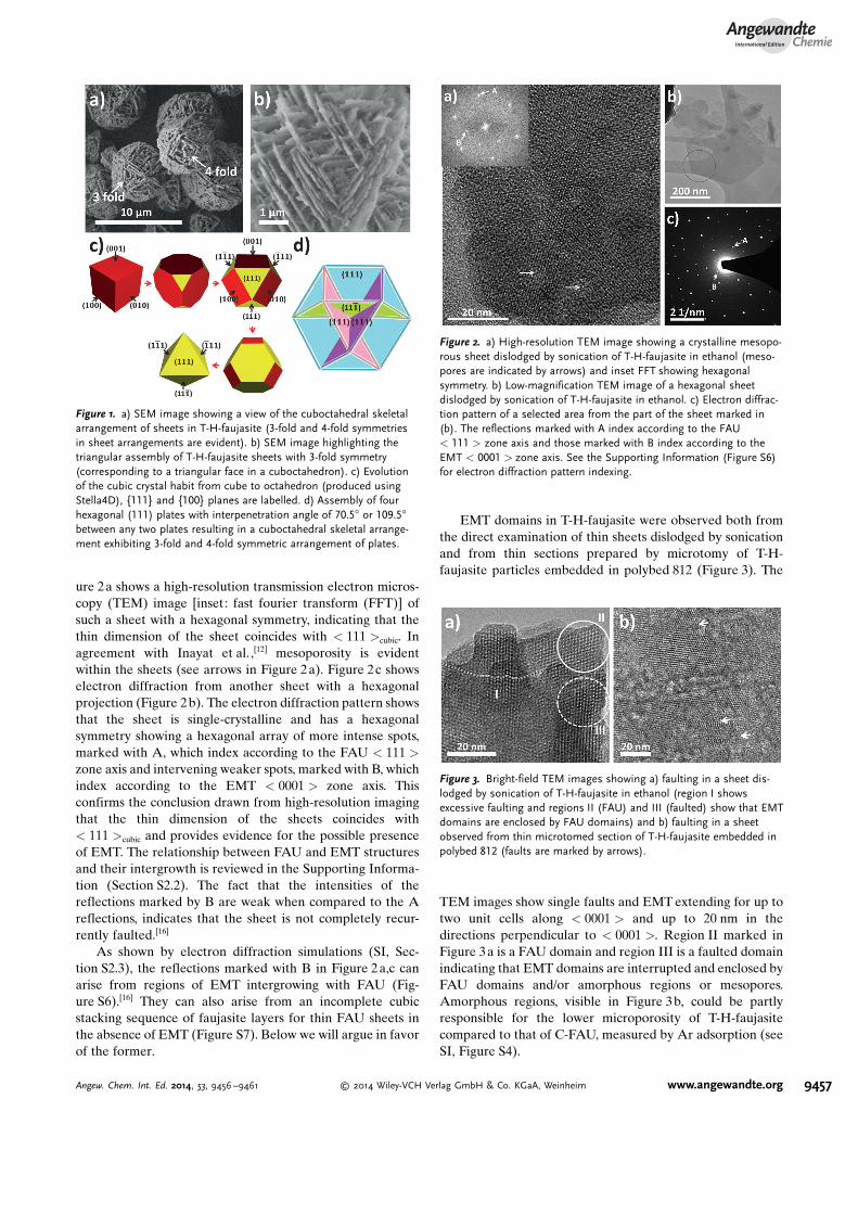
ure 2a shows a high-resolution transmission electron micros-copy (TEM) image [inset: fast fourier transform (FFT)] ofsuch a sheet with a hexagonal symmetry, indicating that thethin dimension of the sheet coincides with < 111 >cubic. Inagreement with Inayat et al. ,[12] mesoporosity is evidentwithin the sheets (see arrows in Figure 2a). Figure 2c showselectron diffraction from another sheet with a hexagonalprojection (Figure 2b). The electron diffraction pattern showsthat the sheet is single-crystalline and has a hexagonalsymmetry showing a hexagonal array of more intense spots,marked with A, which index according to the FAU < 111 >zone axis and intervening weaker spots, marked with B, whichindex according to the EMT < 0001 > zone axis. Thisconfirms the conclusion drawn from high-resolution imagingthat the thin dimension of the sheets coincides with< 111 >cubic and provides evidence for the possible presenceof EMT. The relationship between FAU and EMT structuresand their intergrowth is reviewed in the Supporting Informa-tion (Section S2.2). The fact that the intensities of thereflections marked by B are weak when compared to the Areflections, indicates that the sheet is not completely recur-rently faulted.[16]
As shown by electron diffraction simulations (SI, Sec-tion S2.3), the reflections marked with B in Figure 2 a,c canarise from regions of EMT intergrowing with FAU (Fig-ure S6).[16] They can also arise from an incomplete cubicstacking sequence of faujasite layers for thin FAU sheets inthe absence of EMT (Figure S7). Below we will argue in favorof the former.
EMT domains in T-H-faujasite were observed both fromthe direct examination of thin sheets dislodged by sonicationand from thin sections prepared by microtomy of T-H-faujasite particles embedded in polybed 812 (Figure 3). The
TEM images show single faults and EMT extending for up totwo unit cells along < 0001 > and up to 20 nm in thedirections perpendicular to < 0001 >. Region II marked inFigure 3a is a FAU domain and region III is a faulted domainindicating that EMT domains are interrupted and enclosed byFAU domains and/or amorphous regions or mesopores.Amorphous regions, visible in Figure 3b, could be partlyresponsible for the lower microporosity of T-H-faujasitecompared to that of C-FAU, measured by Ar adsorption (seeSI, Figure S4).
Figure 1. a) SEM image showing a view of the cuboctahedral skeletalarrangement of sheets in T-H-faujasite (3-fold and 4-fold symmetriesin sheet arrangements are evident). b) SEM image highlighting thetriangular assembly of T-H-faujasite sheets with 3-fold symmetry(corresponding to a triangular face in a cuboctahedron). c) Evolutionof the cubic crystal habit from cube to octahedron (produced usingStella4D), {111} and {100} planes are labelled. d) Assembly of fourhexagonal (111) plates with interpenetration angle of 70.58 or 109.58between any two plates resulting in a cuboctahedral skeletal arrange-ment exhibiting 3-fold and 4-fold symmetric arrangement of plates.
Figure 2. a) High-resolution TEM image showing a crystalline mesopo-rous sheet dislodged by sonication of T-H-faujasite in ethanol (meso-pores are indicated by arrows) and inset FFT showing hexagonalsymmetry. b) Low-magnification TEM image of a hexagonal sheetdislodged by sonication of T-H-faujasite in ethanol. c) Electron diffrac-tion pattern of a selected area from the part of the sheet marked in(b). The reflections marked with A index according to the FAU< 111 > zone axis and those marked with B index according to theEMT < 0001 > zone axis. See the Supporting Information (Figure S6)for electron diffraction pattern indexing.
Figure 3. Bright-field TEM images showing a) faulting in a sheet dis-lodged by sonication of T-H-faujasite in ethanol (region I showsexcessive faulting and regions II (FAU) and III (faulted) show that EMTdomains are enclosed by FAU domains) and b) faulting in a sheetobserved from thin microtomed section of T-H-faujasite embedded inpolybed 812 (faults are marked by arrows).
AngewandteChemie
9457Angew. Chem. Int. Ed. 2014, 53, 9456 –9461 � 2014 Wiley-VCH Verlag GmbH & Co. KGaA, Weinheim www.angewandte.org

Additional confirmation of the presence of EMT domains(ca. 20 nm) within the sheets is obtained by electrondiffraction and imaging along the [323]cubic zone axis(Figure 4). The diffraction pattern (Figure 4b) taken fromthe part of the dislodged sheet marked in Figure 4a showsreflections from the [323]cubic zone axis for FAU, mirror FAU(rotated 608 around [111]cubic with respect to FAU alignedalong the [323]cubic), and EMT. This is shown by the simulateddiffraction pattern in Figure 4 c (Figure S8). The same patternof Figure 4b and c was also observed by FFT from highresolution imaging along the [323]cubic zone axis (Figure 4dand FFT inset).
The high-resolution image motif along the [323]cubic zoneaxis can also be used to distinguish FAU-only and FAU/EMTdomains in a sheet. Down this zone axis, the projection ofFAU shows a rectangular pattern while that of FAU/EMTshows a centered pattern with larger features (see Figure S9).Figure 4d shows the experimental TEM image markingrepresentative FAU/EMT domains as determined by the[323] motif. Magnified views of regions I (FAU-only) and II(FAU/EMT) are presented and superimposed by the simu-lated [323] high-resolution images for FAU and FAU/EMT,respectively. This interpretation is also supported by imagefiltering, in which the removal of the EMT reflections fromthe FFT returns a high-resolution image without large,centered features (Figure S10). The [323]cubic view is inagreement with the [111]cubic view. In addition, it has theadvantage of revealing the small portions of included EMTdomains in the predominant FAU matrix.
Scanning transmission electron microscopy (STEM) anal-ysis was performed to identify variations in the Si/Al ratioacross the nanosheets. Figure 5 shows the high-angle annulardark-field (HAADF) STEM images and the STEM energy-
dispersive X-ray (STEM-EDX) Si/Al net count heat maps ofsheets dislodged by sonication in ethanol. The HAADFimages show spots with dark contrast corresponding to themesopores of about 5 nm size. Due to beam damage, thezeolite particles lose their crystallinity. The loss of crystallinityapparently densifies the particles and some shrinkage isevident by observing a sequence of TEM images at differentstages of electron beam exposure (net doses as high as106 electrons per nm2). However, this damage appears to belocal, as there are no apparent changes in the contrastattributed to the mesopores with increased electron beamexposure. Therefore, we believe that despite the electronbeam damage, the Si/Al ratio determined by EDX isrepresentative of that in the undamaged sample. Unlikesilicon and aluminum, sodium migrates fast out of the sampleand is found in the vicinity of the zeolite particles on thecopper grid.
The EDX Si/Al net count heat maps show that, on a 10 nmscale, there is a factor of 2.5 variation in Si/Al across thesheets. At this level of resolution, we find no evidentcorrelation of the Si/Al ratio with morphological featureslike surface steps and pores. Moreover, due to the beamdamage, we are not able to conclude if the differences in Si/Alare associated with the FAU/EMT versus FAU-only domainsdiscussed in Figure 4. This should be the subject of furtherinvestigations.
The edges of the sheets show an apparent higher Si/Alratio compared to the bulk. This is believed to be an artifactresulting from the low counts per pixel at the thin edges. Itarises from the small dwell time needed to limit beam damagecoupled with the reduced interaction volume at the thinparticle edges. This was concluded by careful examination ofthe number of X-ray counts and is supported by X-rayphotoelectron spectroscopy (XPS) data, which do not showa Si-rich surface for the sheets (the Si/Al ratio on the surfaceof the zeolite particles was determined by XPS to be 1.7). Theaverage Si/Al ratios obtained from EDX measurements forboth sheets (excluding edges) is 1.6, which, considering thatwe did not use a calibration standard, is in good agreementwith the Si/Al ratio determined by inductively coupled plasmaoptical emission spectroscopy (ICP-OES) (1.4) and SEM-EDX (1.3).
Figure 4. a) Low-magnification TEM image of a hexagonal sheet dis-lodged by sonication of T-H-faujasite in ethanol. b) Electron diffractionpattern of a selected area from the part of the sheet marked in (a).c) Simulated electron diffraction pattern from the [323]cubic zone axisfor FAU, mirror FAU (rotated 608 around [111]cubic with respect to FAUaligned along [323]cubic), and EMT. d) The [323]cubic high-resolution TEMimage of a sheet (inset FFT) with the FAU/EMT domains marked andmagnified regions I (FAU) and II (FAU/EMT) superimposed by simu-lated [323]cubic high-resolution images.
Figure 5. HAADF-STEM image and STEM-EDX Si/Al net count heatmap of the top (a and b, respectively) and side views (c and d,respectively) of two different sheets. The color code bar on the right ofthe heat maps indicates the colors for a Si/Al ratio range from 0 to 4.
.AngewandteCommunications
9458 www.angewandte.org � 2014 Wiley-VCH Verlag GmbH & Co. KGaA, Weinheim Angew. Chem. Int. Ed. 2014, 53, 9456 –9461

The results presented above show that T-H-faujasite: 1) atthe particle level has a cuboctahedron morphology consistentwith cubic FAU; 2) each cuboctahedron particle consists ofa skeletal arrangement of nanosheets interpenetrating at70.58 or 109.58 ; 3) each nanosheet is thin along the< 111 >cubic axis, and is predominantly composed of FAU,with EMT present in small isolated domains that do not giverise to XRD peaks. The presence of these hardly detectableEMT domains appears to be the necessary ingredient for theformation of T-H-faujasite. We will argue in the following thatEMT not only directs the formation of anisotropic nanosheetsbut also (although it does not act as a connector between thenanosheets) creates the growth instability leading to branch-ing.
According to the Hartman–Perdok theory, FAU {111}faces are classified as “F faces” (flat and slow growing faces),because they have three coplanar periodic bond chains(PBCs) within a slice of the thickness d111.
[17] The perpendic-ular < 111 > directions to these faces are the directions alongwhich the faujasite layers stack and can fault. Intergrowthsare possible because the (111) plane in FAU is identical to the(0001) plane in EMT. For a pure FAU phase, the growth isisotropic. However, if instead of inversion, a mirror plane(fault) forms along one of the four faujasite sheet stackingdirections, a local hexagonal (EMT) structure is createdsupporting anisotropic growth. For EMT, the in-plane growthperpendicular to < 0001 > has been reported to be 15 timesfaster than the growth along < 0001 > and is reflected in thehexagonal platelet morphology of EMT.[18] The fast in-planegrowth of EMT is anticipated by the Hartman–Perdok PBCtheory, which states that the dimension of a crystal alonga particular direction is proportional to the bonding strengthalong that direction. Each sodalite cage has three double-6member ring connections along a (111) plane and only oneconnection either to the faujasite layer above or below. Lessbonding along the < 111 >cubic and the < 0001 >hex axesfavors in-plane growth. This is also anticipated by theBravais–Friedel–Donnay–Harker (BFDH) theory, becausethe < 0001 > spacing in EMT is the largest and therefore thegrowth along this direction is expected to be the slowest.According to these arguments based on PBC and BFDHtheories and prior experimental evidence, the EMT domainsare necessary for the nanosheet morphology to develop. Thesmall size of EMT domains is apparently a result of thesimultaneous multiple nucleation of FAU and EMT on {111}faces in a growth regime favoring 2D nucleation and slower(with respect to nucleation) in-plane propagation such that asgrowth progresses, EMT gets overgrown by the predominantFAU (Figure S11). It is likely that the organosilane surfactantused for the T-H-faujasite synthesis as a mesoporogen alsoacts, upon incorporation at a growth front, to retard thepropagation of the nucleated islands.
This model is supported by atomic force microscopy(AFM) measurements on dislodged T-H-faujasite sheets(deposited on a silicon wafer) that show the presence ofislands with lateral dimensions and heights as small asapproximately 20 nm and 1 nm, respectively (Figure S12).Steps with heights corresponding to one (1.42 nm) and two(2.85 nm) faujasite layers were observed frequently, but not
exclusively, on these surfaces. This surface structure might notbe indicative of the surface structure under growth conditions,but it is consistent with the TEM observations and theproposed growth model.
The remaining question is how branching happens. Ifgrowth proceeds by nucleating FAU and EMT on a single(111) face, a fast propagation in-plane will lead to sheets. Adifferent event has to happen at the branching points. Weargue that EMT island nucleation at the edge of a nanosheetis responsible for branching. EMT nucleation is a randomevent and happens on all {111} faces. If EMT nucleates ona vicinal {111} plane near the edge of the basal plane, it canextend along its fast growing direction before being over-grown by FAU domains. Figure 6 a shows an example, in
which EMT nucleation at the edge of a plate (sheet 1), on its(111) and (111) faces, is followed by branching to formsheet 2. Further growth leads to sheet interpenetration. Otherpossible scenarios are presented in Figure S13 and differentinterpenetration possibilities are presented in Figure S14. Itshould be noted that sheet 2 does not necessarily contactsheet 1 throughout its plane dimensions. This is supported byFigure 6b, which shows out-growing sheets that are laterallymuch smaller than the basal sheet in the image plane.
Sheet 1 in Figure 6a slowly grows perpendicular to itsplane because sheet 2 deprives it of nutrients as the latterextends along its plane and develops as a sheet. This allowsthe structure to branch and grow in a skeletal morphologybefore the voids are filled at long synthesis times and anoctahedral morphology develops (Figure S15). Sheet 2 even-tually thickens and gets surrounded by FAU and branchingcan happen on this sheet as well. This process repeats itself inall four < 111 >cubic directions (Figure 1 d), leading to thehierarchical open house-of-cards arrangement with a well-
Figure 6. Illustration of the branching mechanism in T-H-faujasite.a) Nucleation of EMT close to the edge of sheet 1 on (111) and (111)followed by its extension along its fast growing direction before beingovergrown by FAU domains leads to branching of sheet 2. b) TEMimage highlighting the triangular assembly of T-H-faujasite sheets with3-fold symmetry (corresponding to a triangular face in a cuboctahe-dron; the interconnected sheets were dislodged by sonicating T-H-faujasite in ethanol. c) Structural model showing defect formationwhen the EMT domains on (111) and (111) meet, because EMTcannot coherently bond at 70.58.
AngewandteChemie
9459Angew. Chem. Int. Ed. 2014, 53, 9456 –9461 � 2014 Wiley-VCH Verlag GmbH & Co. KGaA, Weinheim www.angewandte.org

defined interpenetration angle of 70.58. If EMT domains,which nucleated on two different neighboring {111} faces[e.g., (111) and (111)], meet, a defect will form, because EMTcannot coherently bond at 70.58 (Figure 6c). Such a highlydisrupted structure with a large number of defects has alsobeen reported for ZSM-20 prepared using the tetraethylam-monium cation, which also grows as interpenetrating plates,[18]
but with less branching than observed for T-H-faujasite.According to the model, the connection between the sheets isFAU, which is cubic and can coherently connect at angles of70.58.
Our proposed conceptual growth model suggests that therandom nucleation of small EMT islands, which are notdetectable by XRD, on all {111} faces and under growthconditions far from equilibrium, which are characterized bya delicate interplay between surface nucleation, step prop-agation, and branching, lead to the repetitively branchedmorphology. This type of dendritic growth is analogous, yetdistinct, to that observed in more common crystals includingsnowflakes. The latter, for example, form a hexagonal latticethat cannot coherently bond at 70.58 and so they branch onlyin-plane, thereby forming thin hexagonal plates at suitableconditions (Figure 7b).[19] Such branching, along the intrinsic
directions of fast growth, occurs when the growth is fast in thebeginning, but then switches to faceting when supersaturationdrops, developing hexagonal plates.[19] T-H-faujasite appearsto follow the same growth principle (Figure 7a), but since it ispredominantly cubic, it can branch in four directions due tothe growth instability introduced by EMT.
This model for intergrowth is conceptually different fromthe model that was developed for the self-pillared pentasil(SPP).[5] Although both are based on polytypism, it washypothesized for SPP that MFI sheets grow epitaxially froma higher symmetry MEL node that acts as a connector,whereas in the case of T-H-faujasite, the EMT islandsintergrow with FAU to break up the cubic symmetry withina nanosheet. According to the proposed model, hierarchicalfaujasite consisting exclusively of single unit sheets cannot bemade by this branching mechanism, because branching
requires a certain thickness of FAU to be achieved first andrare EMT nucleation to take place at its edges. This, and theearlier work on MFI/MEL,[5] demonstrate that there isa direct link between the polytypes involved and therepetitive branching mechanism leading to the hierarchicalstructures. Once understood, this mechanism will set the stageof what is achievable in terms of characteristic diffusionlength, mesopore size, and other characteristics. Similarinvestigations on other documented intergrowths (e.g.CHA/SOD[21] and ETS-10/ETS-4)[22] are desirable to establishpossible branching mechanisms leading to hierarchical mate-rials.
Received: February 2, 2014Revised: June 12, 2014Published online: July 9, 2014
.Keywords: hierarchical structure · nanosheets ·rotational intergrowth · zeolites · formation mechanism
[1] A. Corma, Chem. Rev. 1997, 97, 2373 – 2419.[2] M. Davis, Nature 2002, 417, 813 – 821.[3] W. Roth, P. Nachtigall, R. Morris, J. Cejka, Chem. Rev. 2014, 114,
4807 – 4837.[4] S. van Donk, A. Broersma, O. Gijzeman, J. van Bokhoven, J.
Bitter, K. de Jong, J. Catal. 2001, 204, 272 – 280.[5] X. Zhang, D. Liu, D. Xu, S. Asahina, K. Cychosz, K. Agrawal, Y.
Wahedi, A. Bhan, S. Hashimi, O. Terasaki, M. Thommes, M.Tsapatsis, Science 2012, 336, 1684 – 1687.
[6] C. Christensen, K. Johannsen, I. Schmidt, C. Christensen, J. Am.Chem. Soc. 2003, 125, 13370 – 13371.
[7] a) J. Garc�a-Mart�nez, M. Johnson, J. Valla, K. Li, J. Ying, Catal.Sci. Technol. 2012, 2, 987 – 994; b) J. Garcia-Martinez, K. Li, G.Krishnaiah, Chem. Commun. 2012, 48, 11841 – 11843.
[8] R. Srivastava, M. Choi, R. Ryoo, Chem. Commun. 2006, 4489 –4491.
[9] M. Choi, K. Na, J. Kim, Y. Sakamoto, O. Terasaki, R. Ryoo,Nature 2009, 461, 246 – 250.
[10] D. Xu, G. Swindlehurst, H. Wu, D. Olson, X. Zhang, M.Tsapatsis, Adv. Funct. Mater. 2014, 24, 201 – 208.
[11] a) R. Chal, C. Gerardin, M. Bulut, S. van Donk, ChemCatChem2011, 3, 67 – 81; b) Y. Tao, H. Kanoh, L. Abrams, K. Kaneko,Chem. Rev. 2006, 106, 896 – 910; c) J. P�rez-Ram�rez, C. Chris-tensen, K. Egeblad, C. Christensen, J. Groen, Chem. Soc. Rev.2008, 37, 2530 – 2542; d) J. Cejka, S. Mintova, Catal. Rev. 2007,49, 457 – 509; e) W. Schmidt, ChemCatChem 2009, 1, 53 – 67; f) S.Lopez-Orozco, A. Inayat, A. Schwab, T. Selvam, W. Schwieger,Adv. Funct. Mater. 2011, 23, 2602 – 2615.
[12] A. Inayat, I. Knoke, E. Spiecker, W. Schwieger, Angew. Chem.2012, 124, 1998 – 2002; Angew. Chem. Int. Ed. 2012, 51, 1962 –1965.
[13] W. Chaikittisilp, Y. Suzuki, R. Mukti, T. Suzuki, K. Sugita, K.Itabashi, A. Shimojima, T. Okubo, Angew. Chem. 2013, 125,3439 – 3443; Angew. Chem. Int. Ed. 2013, 52, 3355 – 3359.
[14] W. Fan, M. Snyder, S. Kumar, P.-S. Lee, W.-C. Yoo, A.McCormick, R. Penn, A. Stein, M. Tsapatsis, Nat. Mater. 2008,7, 984 – 991.
[15] a) M. Choi, H. Cho, R. Srivastava, C. Venkatesan, D.-H. Choi, R.Ryoo, Nat. Mater. 2006, 5, 718 – 723; b) K. Cho, H. Cho, LC.de Menorval, R. Ryoo, Chem. Mater. 2009, 21, 5664 – 5673; c) G.Shanbhag, M. Choi, J. Kim, R. Ryoo, J. Catal. 2009, 264, 88 – 92.
[16] G. Millward, J. Thomas, S. Ramdas, M. Barlow, Proceedings ofthe 6th International Zeolite Conference, Reno, USA, 10 – 15 July
Figure 7. a) Low-magnification TEM image of a mesoporous Faujasitesheet dislodged by sonicating T-H-faujasite in ethanol. b) Snowflake(Reprinted with permission from reference [20]). Copyright 2006 byKenneth Libbrecht.
.AngewandteCommunications
9460 www.angewandte.org � 2014 Wiley-VCH Verlag GmbH & Co. KGaA, Weinheim Angew. Chem. Int. Ed. 2014, 53, 9456 –9461

1983 (Eds.: D. Olson, A. Bisio), Butterworths, Guildford, 1984,pp. 793 – 802.
[17] a) P. Hartman, W. Perdok, Acta Crystallogr. 1955, 8, 49; b) P.Hartman, W. Perdok, Acta Crystallogr. 1955, 8, 525.
[18] O. Terasaki, T. Ohsuna, V. Alfredsson, J. Bovin, D. Watanabe, S.Carr, M. Anderson, Chem. Mater. 1993, 5, 452 – 458.
[19] K. Libbrecht, Rep. Prog. Phys. 2005, 68, 855 – 895.
[20] K. Libbrecht, Ken Libbrecht�s Field Guide to Snowflakes,Voyageur Press, Minnesota, 2006.
[21] T. Wakihara, S. Yamakita, K. Iezumi, T. Okubo, J. Am. Chem.Soc. 2003, 125, 12388 – 12389.
[22] H.-K. Jeong, J. Krohn, K. Sujaoti, M. Tsapatsis, J. Am. Chem.Soc. 2002, 124, 12966 – 12968.
AngewandteChemie
9461Angew. Chem. Int. Ed. 2014, 53, 9456 –9461 � 2014 Wiley-VCH Verlag GmbH & Co. KGaA, Weinheim www.angewandte.org