rotational motion rotational kinematics...
TRANSCRIPT
Rotational MotionRotational Kinematics
Torque
Lana Sheridan
De Anza College
Mar 6, 2020
Last time
• deforming systems
• rotation
• rotational kinematics
Overview
• relating rotational and translational quantities
• torque
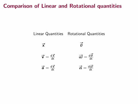
Comparison of Linear and Rotational quantities
Linear Quantities Rotational Quantities
#»x#»
θ
#»v = d #»xdt
#»ω = d#»
θdt
#»a = d #»vdt
#»α = d # »ωdt
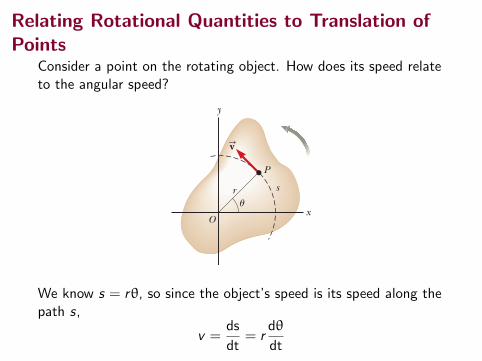
Relating Rotational Quantities to Translation ofPoints
Consider a point on the rotating object. How does its speed relateto the angular speed?
298 Chapter 10 Rotation of a Rigid Object About a Fixed Axis
10.3 Angular and Translational QuantitiesIn this section, we derive some useful relationships between the angular speed and acceleration of a rotating rigid object and the translational speed and acceleration of a point in the object. To do so, we must keep in mind that when a rigid object rotates about a fixed axis as in Figure 10.4, every particle of the object moves in a circle whose center is on the axis of rotation. Because point P in Figure 10.4 moves in a circle, the translational velocity vector vS is always tangent to the circular path and hence is called tangential velocity. The mag-nitude of the tangential velocity of the point P is by definition the tangential speed v 5 ds/dt, where s is the distance traveled by this point measured along the circular path. Recalling that s 5 r u (Eq. 10.1a) and noting that r is constant, we obtain
v 5dsdt
5 r du
dt
Because d u/dt 5 v (see Eq. 10.3), it follows that
v 5 rv (10.10)
As we saw in Equation 4.17, the tangential speed of a point on a rotating rigid object equals the perpendicular distance of that point from the axis of rotation multiplied by the angular speed. Therefore, although every point on the rigid object has the same angular speed, not every point has the same tangential speed because r is not the same for all points on the object. Equation 10.10 shows that the tangential speed of a point on the rotating object increases as one moves outward from the center of rotation, as we would intuitively expect. For example, the outer end of a swinging golf club moves much faster than a point near the handle. We can relate the angular acceleration of the rotating rigid object to the tangen-tial acceleration of the point P by taking the time derivative of v :
at 5dvdt
5 r dv
dt
at 5 ra (10.11)
That is, the tangential component of the translational acceleration of a point on a rotating rigid object equals the point’s perpendicular distance from the axis of rotation multiplied by the angular acceleration. In Section 4.4, we found that a point moving in a circular path undergoes a radial acceleration ar directed toward the center of rotation and whose magnitude is that of the centripetal acceleration v 2/r (Fig. 10.5). Because v 5 rv for a point
Relation between tangential X velocity and angular velocity
Relation between tangential X acceleration and angular
acceleration
Figure 10.4 As a rigid object rotates about the fixed axis (the z axis) through O, the point P has a tangential velocity vS that is always tangent to the circular path of radius r.
y
P
xO
r su
vS
▸ 10.1 c o n t i n u e d
Answer Notice that these questions are translational analogs to parts (A) and (C) of the original problem. The mathemat-ical solution follows exactly the same form. For the displacement, from the particle under constant acceleration model,
Dx 5 xf 2 xi 5 vit 1 12at 2
5 12.00 m/s 2 12.00 s 2 1 12 13.50 m/s2 2 12.00 s 22 5 11.0 m
and for the velocity,
vf 5 vi 1 at 5 2.00 m/s 1 (3.50 m/s2)(2.00 s) 5 9.00 m/s
There is no translational analog to part (B) because translational motion under constant acceleration is not repetitive.
We know s = rθ, so since the object’s speed is its speed along thepath s,
v =ds
dt= r
dθ
dt
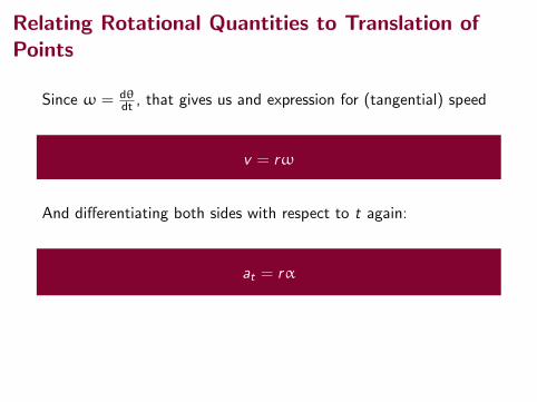
Relating Rotational Quantities to Translation ofPoints
Since ω = dθdt , that gives us and expression for (tangential) speed
v = rω
And differentiating both sides with respect to t again:
at = rα
Notice that the above equation gives the rate of change of speed,which is the tangential acceleration.

Relating Rotational Quantities to Translation ofPoints
Since ω = dθdt , that gives us and expression for (tangential) speed
v = rω
And differentiating both sides with respect to t again:
at = rα
Notice that the above equation gives the rate of change of speed,which is the tangential acceleration.
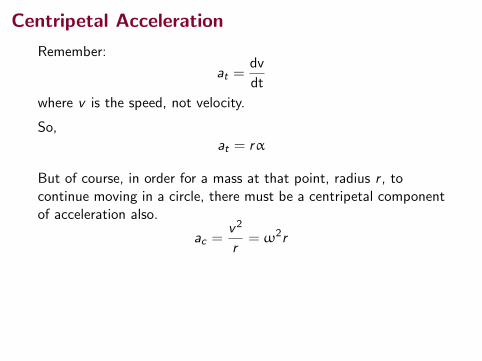
Centripetal Acceleration
Remember:
at =dv
dt
where v is the speed, not velocity.
So,at = rα
But of course, in order for a mass at that point, radius r , tocontinue moving in a circle, there must be a centripetal componentof acceleration also.
ac =v2
r= ω2r
For a rigid object, the force that supplies this acceleration will besome internal forces between the mass at the rotating point andthe other masses in the object. Those are the forces that hold theobject together.
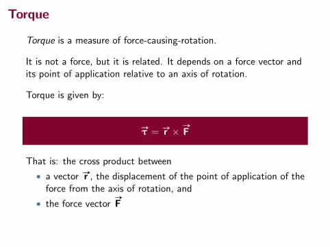
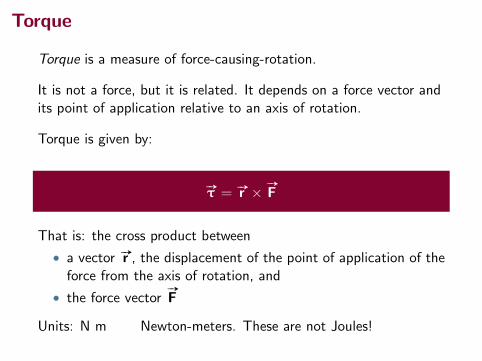
Torque
Torque is a measure of force-causing-rotation.
It is not a force, but it is related. It depends on a force vector andits point of application relative to an axis of rotation.
Torque is given by:
#»τ = #»r × #»
F
That is: the cross product between
• a vector #»r , the displacement of the point of application of theforce from the axis of rotation, and
• the force vector#»
F
Units: N m Newton-meters. These are not Joules!

Torque
300 Chapter 10 Rotation of a Rigid Object About a Fixed Axis
(C) What is the angular acceleration of the compact disc over the 4 473-s time interval?
Categorize We again model the disc as a rigid object under constant angular acceleration. In this case, Equation 10.6 gives the value of the constant angular acceleration. Another approach is to use Equation 10.4 to find the average angular acceleration. In this case, we are not assuming the angular acceleration is constant. The answer is the same from both equations; only the interpretation of the result is different.
S O L U T I O N
Analyze Use Equation 10.6 to find the angular acceleration: a 5
vf 2 vi
t5
22 rad/s 2 57 rad/s4 473 s
5 27.6 3 1023 rad/s2
Finalize The disc experiences a very gradual decrease in its rotation rate, as expected from the long time interval required for the angular speed to change from the initial value to the final value. In reality, the angular acceleration of the disc is not constant. Problem 90 allows you to explore the actual time behavior of the angular acceleration.
Do the same for the outer track: vf 5vrf
51.3 m/s
5.8 3 1022 m5 22 rad/s 5 2.1 3 102 rev/min
Use Equation 10.9 to find the angular displacement of the disc at t 5 4 473 s:
Du 5 uf 2 ui 5 12 1vi 1 vf 2 t
5 12 157 rad/s 1 22 rad/s 2 14 473 s 2 5 1.8 3 105 rad
The CD player adjusts the angular speed v of the disc within this range so that information moves past the objective lens at a constant rate.
(B) The maximum playing time of a standard music disc is 74 min and 33 s. How many revolutions does the disc make during that time?
Categorize From part (A), the angular speed decreases as the disc plays. Let us assume it decreases steadily, with a constant. We can then apply the rigid object under constant angular acceleration model to the disc.
Analyze If t 5 0 is the instant the disc begins rotating, with angular speed of 57 rad/s, the final value of the time t is (74 min)(60 s/min) 1 33 s 5 4 473 s. We are looking for the angular displacement Du during this time interval.
Convert this angular displacement to revolutions: Du 5 11.8 3 105 rad 2 a 1 rev2p rad
b 5 2.8 3 104 rev
▸ 10.2 c o n t i n u e d
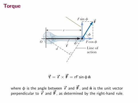
10.4 TorqueIn our study of translational motion, after investigating the description of motion, we studied the cause of changes in motion: force. We follow the same plan here: What is the cause of changes in rotational motion? Imagine trying to rotate a door by applying a force of magnitude F perpendic-ular to the door surface near the hinges and then at various distances from the hinges. You will achieve a more rapid rate of rotation for the door by applying the force near the doorknob than by applying it near the hinges. When a force is exerted on a rigid object pivoted about an axis, the object tends to rotate about that axis. The tendency of a force to rotate an object about some axis is measured by a quantity called torque tS(Greek letter tau). Torque is a vector, but we will consider only its magnitude here; we will explore its vector nature in Chapter 11. Consider the wrench in Figure 10.7 that we wish to rotate around an axis that is perpendicular to the page and passes through the center of the bolt. The applied
r
F sin f
F cos f
d
O
Line ofaction
f
The component F sin f tends to rotate the wrench about an axis through O.
f
FS
rS
Figure 10.7 The force FS
has a greater rotating tendency about an axis through O as F increases and as the moment arm d increases.
S O L U T I O N
#»τ = #»r × #»
F = rF sinφ n
where φ is the angle between #»r and#»
F , and n is the unit vectorperpendicular to #»r and
#»
F , as determined by the right-hand rule.
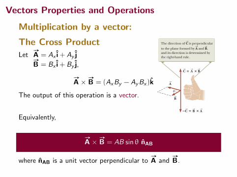
Vectors Properties and Operations
Multiplication by a vector:
The Cross ProductLet
#»
A = Ax i+ Ay j#»
B = Bx i+ By j,
#»
A × #»
B = (AxBy − AyBx)k
The output of this operation is a vector.
Equivalently,
#»
A × #»
B = AB sin θ nAB
where nAB is a unit vector perpendicular to#»
A and#»
B.
336 Chapter 11 Angular Momentum
We now give a formal definition of the vector product. Given any two vectors AS
and BS
, the vector product AS
3 BS
is defined as a third vector CS
, which has a magnitude of AB sin u, where u is the angle between A
S and B
S. That is, if C
S is
given by C
S5 A
S3 B
S (11.2)
its magnitude is C 5 AB sin u (11.3)
The quantity AB sin u is equal to the area of the parallelogram formed by AS
and BS
as shown in Figure 11.2. The direction of CS
is perpendicular to the plane formed by A
S and B
S, and the best way to determine this direction is to use the right-hand
rule illustrated in Figure 11.2. The four fingers of the right hand are pointed along AS
and then “wrapped” in the direction that would rotate AS
into BS
through the angle u. The direction of the upright thumb is the direction of A
S3 B
S5 C
S.
Because of the notation, AS
3 BS
is often read “ AS
cross BS
,” so the vector product is also called the cross product. Some properties of the vector product that follow from its definition are as follows:
1. Unlike the scalar product, the vector product is not commutative. Instead, the order in which the two vectors are multiplied in a vector product is important:
AS
3 BS
5 2 BS
3 AS
(11.4) Therefore, if you change the order of the vectors in a vector product, you
must change the sign. You can easily verify this relationship with the right-hand rule.
2. If AS
is parallel to BS
(u 5 0 or 1808), then AS
3 BS
5 0; therefore, it follows that A
S3 A
S5 0.
3. If AS
is perpendicular to BS
, then 0 AS 3 BS 0 5 AB.
4. The vector product obeys the distributive law:
AS
3 1 BS
1 CS 2 5 A
S3 B
S1 A
S3 C
S (11.5)
5. The derivative of the vector product with respect to some variable such as t is
ddt
1 AS
3 BS 2 5
d AS
dt3 B
S1 A
S3
d BS
dt (11.6)
where it is important to preserve the multiplicative order of the terms on the right side in view of Equation 11.4.
It is left as an exercise (Problem 4) to show from Equations 11.3 and 11.4 and from the definition of unit vectors that the cross products of the unit vectors i, j, and k obey the following rules:
i 3 i 5 j 3 j 5 k 3 k 5 0 (11.7a)
i 3 j 5 2 j 3 i 5 k (11.7b)
j 3 k 5 2k 3 j 5 i (11.7c)
k 3 i 5 2 i 3 k 5 j (11.7d)
Signs are interchangeable in cross products. For example, AS
3 12BS 2 5 2 A
S3 B
S
and i 3 12 j 2 5 2 i 3 j. The cross product of any two vectors A
S and B
S can be expressed in the follow-
ing determinant form:
AS
3 BS
5 † i j kAx Ay Az
Bx By Bz
† 5 `Ay Az
By Bz` i 1 `Az Ax
Bz Bx` j 1 `Ax Ay
Bx By` k
Properties of the Xvector product
Cross products of Xunit vectors
Pitfall Prevention 11.1The Vector Product Is a Vector Remember that the result of tak-ing a vector product between two vectors is a third vector. Equation 11.3 gives only the magnitude of this vector.
Figure 11.1 The torque vector tS lies in a direction perpendicular to the plane formed by the posi-tion vector rS and the applied force vector F
S. In the situation shown,
rS and FS
lie in the xy plane, so the torque is along the z axis.
O
P
x
y
z
f
rS
rS
FS
FS
! !tS
" # !
# !
u
AS
BS
CS
AS
BS
AS
BS
CS
S S
SThe direction of C is perpendicular to the plane formed by A and B,and its direction is determined by the right-hand rule.
Figure 11.2 The vector product AS
3 BS
is a third vector CS
having a magnitude AB sin u equal to the area of the parallelogram shown.
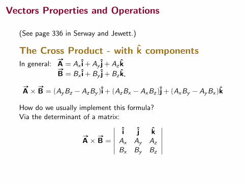
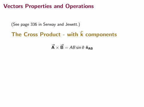
Vectors Properties and Operations
(See page 336 in Serway and Jewett.)
The Cross Product - with k componentsIn general:
#»
A = Ax i+ Ay j+ Az k#»
B = Bx i+ By j+ Bz k,
#»
A × #»
B = (AyBz − AzBy )i+ (AzBx − AxBz )j+ (AxBy − AyBx)k
How do we usually implement this formula?Via the determinant of a matrix:
#»
A × #»
B =
∣∣∣∣∣∣i j kAx Ay Az
Bx By Bz
∣∣∣∣∣∣
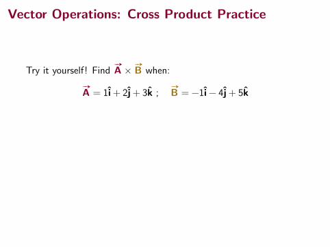
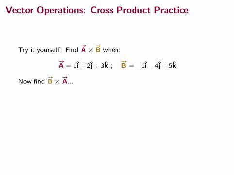
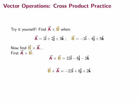
Vector Operations: Cross Product Practice
Try it yourself! Find#»
A × #»
B when:
#»
A = 1i+ 2j+ 3k ;#»
B = −1i− 4j+ 5k
Now find#»
B × #»
A...First
#»
A × #»
B:#»
A × #»
B = 22i− 8j− 2k
#»
B × #»
A = −22i+ 8j+ 2k
Vector Operations: Cross Product Practice
Try it yourself! Find#»
A × #»
B when:
#»
A = 1i+ 2j+ 3k ;#»
B = −1i− 4j+ 5k
Now find#»
B × #»
A...
First#»
A × #»
B:#»
A × #»
B = 22i− 8j− 2k
#»
B × #»
A = −22i+ 8j+ 2k

Vector Operations: Cross Product Practice
Try it yourself! Find#»
A × #»
B when:
#»
A = 1i+ 2j+ 3k ;#»
B = −1i− 4j+ 5k
Now find#»
B × #»
A...First
#»
A × #»
B:#»
A × #»
B = 22i− 8j− 2k
#»
B × #»
A = −22i+ 8j+ 2k
Vector Operations: Cross Product Practice
Try it yourself! Find#»
A × #»
B when:
#»
A = 1i+ 2j+ 3k ;#»
B = −1i− 4j+ 5k
Now find#»
B × #»
A...First
#»
A × #»
B:#»
A × #»
B = 22i− 8j− 2k
#»
B × #»
A = −22i+ 8j+ 2k
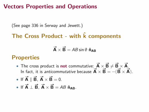
Vectors Properties and Operations
(See page 336 in Serway and Jewett.)
The Cross Product - with k components
#»
A × #»
B = AB sin θ nAB
Properties
• The cross product is not commutative:#»
A × #»
B 6= #»
B × #»
A.In fact, it is anticommutative because
#»
A × #»
B = −(#»
B × #»
A).
• If#»
A ‖ #»
B,#»
A × #»
B = 0.
• If#»
A ⊥ #»
B,#»
A × #»
B = AB nAB.
Torque
300 Chapter 10 Rotation of a Rigid Object About a Fixed Axis
(C) What is the angular acceleration of the compact disc over the 4 473-s time interval?
Categorize We again model the disc as a rigid object under constant angular acceleration. In this case, Equation 10.6 gives the value of the constant angular acceleration. Another approach is to use Equation 10.4 to find the average angular acceleration. In this case, we are not assuming the angular acceleration is constant. The answer is the same from both equations; only the interpretation of the result is different.
S O L U T I O N
Analyze Use Equation 10.6 to find the angular acceleration: a 5
vf 2 vi
t5
22 rad/s 2 57 rad/s4 473 s
5 27.6 3 1023 rad/s2
Finalize The disc experiences a very gradual decrease in its rotation rate, as expected from the long time interval required for the angular speed to change from the initial value to the final value. In reality, the angular acceleration of the disc is not constant. Problem 90 allows you to explore the actual time behavior of the angular acceleration.
Do the same for the outer track: vf 5vrf
51.3 m/s
5.8 3 1022 m5 22 rad/s 5 2.1 3 102 rev/min
Use Equation 10.9 to find the angular displacement of the disc at t 5 4 473 s:
Du 5 uf 2 ui 5 12 1vi 1 vf 2 t
5 12 157 rad/s 1 22 rad/s 2 14 473 s 2 5 1.8 3 105 rad
The CD player adjusts the angular speed v of the disc within this range so that information moves past the objective lens at a constant rate.
(B) The maximum playing time of a standard music disc is 74 min and 33 s. How many revolutions does the disc make during that time?
Categorize From part (A), the angular speed decreases as the disc plays. Let us assume it decreases steadily, with a constant. We can then apply the rigid object under constant angular acceleration model to the disc.
Analyze If t 5 0 is the instant the disc begins rotating, with angular speed of 57 rad/s, the final value of the time t is (74 min)(60 s/min) 1 33 s 5 4 473 s. We are looking for the angular displacement Du during this time interval.
Convert this angular displacement to revolutions: Du 5 11.8 3 105 rad 2 a 1 rev2p rad
b 5 2.8 3 104 rev
▸ 10.2 c o n t i n u e d
10.4 TorqueIn our study of translational motion, after investigating the description of motion, we studied the cause of changes in motion: force. We follow the same plan here: What is the cause of changes in rotational motion? Imagine trying to rotate a door by applying a force of magnitude F perpendic-ular to the door surface near the hinges and then at various distances from the hinges. You will achieve a more rapid rate of rotation for the door by applying the force near the doorknob than by applying it near the hinges. When a force is exerted on a rigid object pivoted about an axis, the object tends to rotate about that axis. The tendency of a force to rotate an object about some axis is measured by a quantity called torque tS(Greek letter tau). Torque is a vector, but we will consider only its magnitude here; we will explore its vector nature in Chapter 11. Consider the wrench in Figure 10.7 that we wish to rotate around an axis that is perpendicular to the page and passes through the center of the bolt. The applied
r
F sin f
F cos f
d
O
Line ofaction
f
The component F sin f tends to rotate the wrench about an axis through O.
f
FS
rS
Figure 10.7 The force FS
has a greater rotating tendency about an axis through O as F increases and as the moment arm d increases.
S O L U T I O N
#»τ = #»r × #»
F = rF sinφ n
where φ is the angle between #»r and#»
F , and n is the unit vectorperpendicular to #»r and
#»
F , as determined by the right-hand rule.

Torque
Diagram also illustrates two points of view about torque:
300 Chapter 10 Rotation of a Rigid Object About a Fixed Axis
(C) What is the angular acceleration of the compact disc over the 4 473-s time interval?
Categorize We again model the disc as a rigid object under constant angular acceleration. In this case, Equation 10.6 gives the value of the constant angular acceleration. Another approach is to use Equation 10.4 to find the average angular acceleration. In this case, we are not assuming the angular acceleration is constant. The answer is the same from both equations; only the interpretation of the result is different.
S O L U T I O N
Analyze Use Equation 10.6 to find the angular acceleration: a 5
vf 2 vi
t5
22 rad/s 2 57 rad/s4 473 s
5 27.6 3 1023 rad/s2
Finalize The disc experiences a very gradual decrease in its rotation rate, as expected from the long time interval required for the angular speed to change from the initial value to the final value. In reality, the angular acceleration of the disc is not constant. Problem 90 allows you to explore the actual time behavior of the angular acceleration.
Do the same for the outer track: vf 5vrf
51.3 m/s
5.8 3 1022 m5 22 rad/s 5 2.1 3 102 rev/min
Use Equation 10.9 to find the angular displacement of the disc at t 5 4 473 s:
Du 5 uf 2 ui 5 12 1vi 1 vf 2 t
5 12 157 rad/s 1 22 rad/s 2 14 473 s 2 5 1.8 3 105 rad
The CD player adjusts the angular speed v of the disc within this range so that information moves past the objective lens at a constant rate.
(B) The maximum playing time of a standard music disc is 74 min and 33 s. How many revolutions does the disc make during that time?
Categorize From part (A), the angular speed decreases as the disc plays. Let us assume it decreases steadily, with a constant. We can then apply the rigid object under constant angular acceleration model to the disc.
Analyze If t 5 0 is the instant the disc begins rotating, with angular speed of 57 rad/s, the final value of the time t is (74 min)(60 s/min) 1 33 s 5 4 473 s. We are looking for the angular displacement Du during this time interval.
Convert this angular displacement to revolutions: Du 5 11.8 3 105 rad 2 a 1 rev2p rad
b 5 2.8 3 104 rev
▸ 10.2 c o n t i n u e d
10.4 TorqueIn our study of translational motion, after investigating the description of motion, we studied the cause of changes in motion: force. We follow the same plan here: What is the cause of changes in rotational motion? Imagine trying to rotate a door by applying a force of magnitude F perpendic-ular to the door surface near the hinges and then at various distances from the hinges. You will achieve a more rapid rate of rotation for the door by applying the force near the doorknob than by applying it near the hinges. When a force is exerted on a rigid object pivoted about an axis, the object tends to rotate about that axis. The tendency of a force to rotate an object about some axis is measured by a quantity called torque tS(Greek letter tau). Torque is a vector, but we will consider only its magnitude here; we will explore its vector nature in Chapter 11. Consider the wrench in Figure 10.7 that we wish to rotate around an axis that is perpendicular to the page and passes through the center of the bolt. The applied
r
F sin f
F cos f
d
O
Line ofaction
f
The component F sin f tends to rotate the wrench about an axis through O.
f
FS
rS
Figure 10.7 The force FS
has a greater rotating tendency about an axis through O as F increases and as the moment arm d increases.
S O L U T I O N
#»τ = r(F sinφ) n
or#»τ = (r sinφ)F n
In the diagram, the distance d = r sinφ and is called the “momentarm” or “lever arm” of the torque.
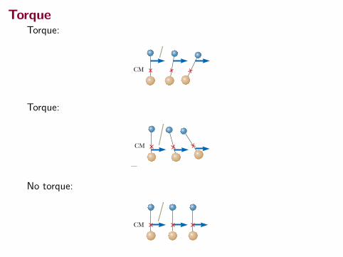
TorqueTorque:
268 Chapter 9 Linear Momentum and Collisions
is applied at the center of mass, the system moves in the direction of the force with-out rotating (see Fig. 9.13c). The center of mass of an object can be located with this procedure. The center of mass of the pair of particles described in Figure 9.14 is located on the x axis and lies somewhere between the particles. Its x coordinate is given by
xCM ;m1x1 1 m2x2
m1 1 m2 (9.28)
For example, if x1 5 0, x2 5 d, and m2 5 2m1, we find that xCM 5 23d. That is, the
center of mass lies closer to the more massive particle. If the two masses are equal, the center of mass lies midway between the particles. We can extend this concept to a system of many particles with masses mi in three dimensions. The x coordinate of the center of mass of n particles is defined to be
xCM ;m1x1 1 m2x2 1 m3x3 1 c1 mnxn
m1 1 m2 1 m3 1 c1 mn5
ai
mixi
ai
mi
5a
imixi
M5
1M a
imixi
(9.29)
where xi is the x coordinate of the ith particle and the total mass is M ; oi mi where the sum runs over all n particles. The y and z coordinates of the center of mass are similarly defined by the equations
yCM ;1M a
imiyi and zCM ;
1M a
imizi (9.30)
The center of mass can be located in three dimensions by its position vector rSCM. The components of this vector are xCM, yCM, and zCM, defined in Equations 9.29 and 9.30. Therefore,
rSCM 5 xCM i 1 yCM j 1 zCM k 51M a
imixi i 1
1M a
imiyi j 1
1M a
imizi k
rSCM ;1M a
imi r
Si (9.31)
where rSi is the position vector of the ith particle, defined by
rSi ; xi i 1 yi j 1 zi k
Although locating the center of mass for an extended, continuous object is some-what more cumbersome than locating the center of mass of a small number of par-ticles, the basic ideas we have discussed still apply. Think of an extended object as a system containing a large number of small mass elements such as the cube in Figure 9.15. Because the separation between elements is very small, the object can be con-sidered to have a continuous mass distribution. By dividing the object into elements of mass Dmi with coordinates xi, yi, zi, we see that the x coordinate of the center of mass is approximately
xCM <1M
ai
xi Dmi
with similar expressions for yCM and zCM. If we let the number of elements n approach infinity, the size of each element approaches zero and xCM is given pre-cisely. In this limit, we replace the sum by an integral and Dmi by the differential element dm:
xCM 5 limDmi S 0
1M
ai
xi Dmi 51M
3 x dm (9.32)
Likewise, for yCM and zCM we obtain
yCM 51M
3 y dm and zCM 51M
3 z dm (9.33)
CM
CM
CM
a
b
c
The system rotates clockwise when a force is applied above the center of mass.
The system rotates counter-clockwise when a force is applied below the center of mass.
The system moves in the direction of the force without rotating when a force is applied at the center of mass.
Figure 9.13 A force is applied to a system of two particles of unequal mass connected by a light, rigid rod.
Figure 9.14 The center of mass of two particles of unequal mass on the x axis is located at xCM, a point between the particles, closer to the one having the larger mass.
y
m1
x1
x 2
CM
m 2
x
x CM
Torque:
268 Chapter 9 Linear Momentum and Collisions
is applied at the center of mass, the system moves in the direction of the force with-out rotating (see Fig. 9.13c). The center of mass of an object can be located with this procedure. The center of mass of the pair of particles described in Figure 9.14 is located on the x axis and lies somewhere between the particles. Its x coordinate is given by
xCM ;m1x1 1 m2x2
m1 1 m2 (9.28)
For example, if x1 5 0, x2 5 d, and m2 5 2m1, we find that xCM 5 23d. That is, the
center of mass lies closer to the more massive particle. If the two masses are equal, the center of mass lies midway between the particles. We can extend this concept to a system of many particles with masses mi in three dimensions. The x coordinate of the center of mass of n particles is defined to be
xCM ;m1x1 1 m2x2 1 m3x3 1 c1 mnxn
m1 1 m2 1 m3 1 c1 mn5
ai
mixi
ai
mi
5a
imixi
M5
1M a
imixi
(9.29)
where xi is the x coordinate of the ith particle and the total mass is M ; oi mi where the sum runs over all n particles. The y and z coordinates of the center of mass are similarly defined by the equations
yCM ;1M a
imiyi and zCM ;
1M a
imizi (9.30)
The center of mass can be located in three dimensions by its position vector rSCM. The components of this vector are xCM, yCM, and zCM, defined in Equations 9.29 and 9.30. Therefore,
rSCM 5 xCM i 1 yCM j 1 zCM k 51M a
imixi i 1
1M a
imiyi j 1
1M a
imizi k
rSCM ;1M a
imi r
Si (9.31)
where rSi is the position vector of the ith particle, defined by
rSi ; xi i 1 yi j 1 zi k
Although locating the center of mass for an extended, continuous object is some-what more cumbersome than locating the center of mass of a small number of par-ticles, the basic ideas we have discussed still apply. Think of an extended object as a system containing a large number of small mass elements such as the cube in Figure 9.15. Because the separation between elements is very small, the object can be con-sidered to have a continuous mass distribution. By dividing the object into elements of mass Dmi with coordinates xi, yi, zi, we see that the x coordinate of the center of mass is approximately
xCM <1M
ai
xi Dmi
with similar expressions for yCM and zCM. If we let the number of elements n approach infinity, the size of each element approaches zero and xCM is given pre-cisely. In this limit, we replace the sum by an integral and Dmi by the differential element dm:
xCM 5 limDmi S 0
1M
ai
xi Dmi 51M
3 x dm (9.32)
Likewise, for yCM and zCM we obtain
yCM 51M
3 y dm and zCM 51M
3 z dm (9.33)
CM
CM
CM
a
b
c
The system rotates clockwise when a force is applied above the center of mass.
The system rotates counter-clockwise when a force is applied below the center of mass.
The system moves in the direction of the force without rotating when a force is applied at the center of mass.
Figure 9.13 A force is applied to a system of two particles of unequal mass connected by a light, rigid rod.
Figure 9.14 The center of mass of two particles of unequal mass on the x axis is located at xCM, a point between the particles, closer to the one having the larger mass.
y
m1
x1
x 2
CM
m 2
x
x CM
No torque:
268 Chapter 9 Linear Momentum and Collisions
is applied at the center of mass, the system moves in the direction of the force with-out rotating (see Fig. 9.13c). The center of mass of an object can be located with this procedure. The center of mass of the pair of particles described in Figure 9.14 is located on the x axis and lies somewhere between the particles. Its x coordinate is given by
xCM ;m1x1 1 m2x2
m1 1 m2 (9.28)
For example, if x1 5 0, x2 5 d, and m2 5 2m1, we find that xCM 5 23d. That is, the
center of mass lies closer to the more massive particle. If the two masses are equal, the center of mass lies midway between the particles. We can extend this concept to a system of many particles with masses mi in three dimensions. The x coordinate of the center of mass of n particles is defined to be
xCM ;m1x1 1 m2x2 1 m3x3 1 c1 mnxn
m1 1 m2 1 m3 1 c1 mn5
ai
mixi
ai
mi
5a
imixi
M5
1M a
imixi
(9.29)
where xi is the x coordinate of the ith particle and the total mass is M ; oi mi where the sum runs over all n particles. The y and z coordinates of the center of mass are similarly defined by the equations
yCM ;1M a
imiyi and zCM ;
1M a
imizi (9.30)
The center of mass can be located in three dimensions by its position vector rSCM. The components of this vector are xCM, yCM, and zCM, defined in Equations 9.29 and 9.30. Therefore,
rSCM 5 xCM i 1 yCM j 1 zCM k 51M a
imixi i 1
1M a
imiyi j 1
1M a
imizi k
rSCM ;1M a
imi r
Si (9.31)
where rSi is the position vector of the ith particle, defined by
rSi ; xi i 1 yi j 1 zi k
Although locating the center of mass for an extended, continuous object is some-what more cumbersome than locating the center of mass of a small number of par-ticles, the basic ideas we have discussed still apply. Think of an extended object as a system containing a large number of small mass elements such as the cube in Figure 9.15. Because the separation between elements is very small, the object can be con-sidered to have a continuous mass distribution. By dividing the object into elements of mass Dmi with coordinates xi, yi, zi, we see that the x coordinate of the center of mass is approximately
xCM <1M
ai
xi Dmi
with similar expressions for yCM and zCM. If we let the number of elements n approach infinity, the size of each element approaches zero and xCM is given pre-cisely. In this limit, we replace the sum by an integral and Dmi by the differential element dm:
xCM 5 limDmi S 0
1M
ai
xi Dmi 51M
3 x dm (9.32)
Likewise, for yCM and zCM we obtain
yCM 51M
3 y dm and zCM 51M
3 z dm (9.33)
CM
CM
CM
a
b
c
The system rotates clockwise when a force is applied above the center of mass.
The system rotates counter-clockwise when a force is applied below the center of mass.
The system moves in the direction of the force without rotating when a force is applied at the center of mass.
Figure 9.13 A force is applied to a system of two particles of unequal mass connected by a light, rigid rod.
Figure 9.14 The center of mass of two particles of unequal mass on the x axis is located at xCM, a point between the particles, closer to the one having the larger mass.
y
m1
x1
x 2
CM
m 2
x
x CM

Question
A torque is supplied by applying a force at point A. To produce thesame torque, the force applied at point B must be:
(A) greater
(B) less
(C) the same1Image from Harbor Freight Tools, www.harborfreight.com
B
A
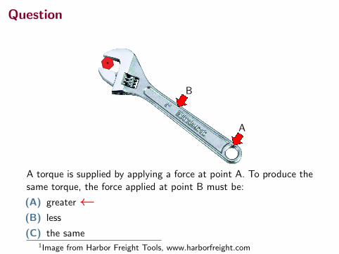
Question
A torque is supplied by applying a force at point A. To produce thesame torque, the force applied at point B must be:
(A) greater←(B) less
(C) the same1Image from Harbor Freight Tools, www.harborfreight.com
B
A
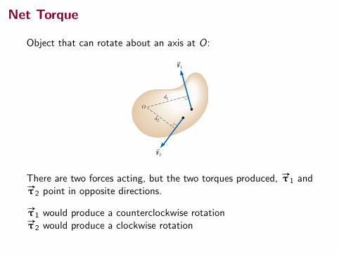
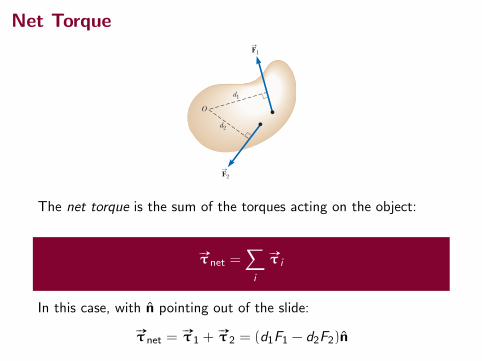
Net Torque
Object that can rotate about an axis at O:
10.4 Torque 301
Pitfall Prevention 10.4Torque Depends on Your Choice of Axis There is no unique value of the torque on an object. Its value depends on your choice of rotation axis.
O
d2
d1
F2S
F1S
Figure 10.8 The force FS
1 tends to rotate the object counterclock-wise about an axis through O, and FS
2 tends to rotate it clockwise.
force FS
acts at an angle f to the horizontal. We define the magnitude of the torque associated with the force F
S around the axis passing through O by the expression
t ; rF sin f 5 Fd (10.14)
where r is the distance between the rotation axis and the point of application of FS
, and d is the perpendicular distance from the rotation axis to the line of action of FS
. (The line of action of a force is an imaginary line extending out both ends of the vector representing the force. The dashed line extending from the tail of F
S in Fig.
10.7 is part of the line of action of FS
.) From the right triangle in Figure 10.7 that has the wrench as its hypotenuse, we see that d 5 r sin f. The quantity d is called the moment arm (or lever arm) of F
S.
In Figure 10.7, the only component of FS
that tends to cause rotation of the wrench around an axis through O is F sin f, the component perpendicular to a line drawn from the rotation axis to the point of application of the force. The hori-zontal component F cos f, because its line of action passes through O, has no ten-dency to produce rotation about an axis passing through O. From the definition of torque, the rotating tendency increases as F increases and as d increases, which explains why it is easier to rotate a door if we push at the doorknob rather than at a point close to the hinges. We also want to apply our push as closely perpendicular to the door as we can so that f is close to 908. Pushing sideways on the doorknob (f 5 0) will not cause the door to rotate. If two or more forces act on a rigid object as in Figure 10.8, each tends to pro-duce rotation about the axis through O. In this example, F
S2 tends to rotate the
object clockwise and FS
1 tends to rotate it counterclockwise. We use the convention that the sign of the torque resulting from a force is positive if the turning tendency of the force is counterclockwise and negative if the turning tendency is clockwise. For Example, in Figure 10.8, the torque resulting from F
S1, which has a moment arm
d1, is positive and equal to 1F1d1; the torque from FS
2 is negative and equal to 2F2d2. Hence, the net torque about an axis through O is
o t 5 t1 1 t2 5 F1d1 2 F2d2
Torque should not be confused with force. Forces can cause a change in transla-tional motion as described by Newton’s second law. Forces can also cause a change in rotational motion, but the effectiveness of the forces in causing this change depends on both the magnitudes of the forces and the moment arms of the forces, in the combination we call torque. Torque has units of force times length—newton meters (N ? m) in SI units—and should be reported in these units. Do not confuse torque and work, which have the same units but are very different concepts.
Q uick Quiz 10.4 (i) If you are trying to loosen a stubborn screw from a piece of wood with a screwdriver and fail, should you find a screwdriver for which the handle is (a) longer or (b) fatter? (ii) If you are trying to loosen a stubborn bolt from a piece of metal with a wrench and fail, should you find a wrench for which the handle is (a) longer or (b) fatter?
�W Moment arm
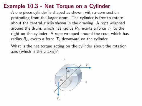
Example 10.3 The Net Torque on a Cylinder
A one-piece cylinder is shaped as shown in Figure 10.9, with a core section protrud-ing from the larger drum. The cylinder is free to rotate about the central z axis shown in the drawing. A rope wrapped around the drum, which has radius R1, exerts a force T
S1 to the right on the cylinder. A rope wrapped around the core,
which has radius R2, exerts a force TS
2 downward on the cylinder.
(A) What is the net torque acting on the cylinder about the rotation axis (which is the z axis in Fig. 10.9)?
z
x
y
R 1
R 2
O
T1S
T2S
Figure 10.9 (Example 10.3) A solid cylinder pivoted about the z axis through O. The moment arm of T
S1 is
R1, and the moment arm of TS
2 is R2.continued
There are two forces acting, but the two torques produced, #»τ 1 and#»τ 2 point in opposite directions.
#»τ 1 would produce a counterclockwise rotation#»τ 2 would produce a clockwise rotation
Net Torque
10.4 Torque 301
Pitfall Prevention 10.4Torque Depends on Your Choice of Axis There is no unique value of the torque on an object. Its value depends on your choice of rotation axis.
O
d2
d1
F2S
F1S
Figure 10.8 The force FS
1 tends to rotate the object counterclock-wise about an axis through O, and FS
2 tends to rotate it clockwise.
force FS
acts at an angle f to the horizontal. We define the magnitude of the torque associated with the force F
S around the axis passing through O by the expression
t ; rF sin f 5 Fd (10.14)
where r is the distance between the rotation axis and the point of application of FS
, and d is the perpendicular distance from the rotation axis to the line of action of FS
. (The line of action of a force is an imaginary line extending out both ends of the vector representing the force. The dashed line extending from the tail of F
S in Fig.
10.7 is part of the line of action of FS
.) From the right triangle in Figure 10.7 that has the wrench as its hypotenuse, we see that d 5 r sin f. The quantity d is called the moment arm (or lever arm) of F
S.
In Figure 10.7, the only component of FS
that tends to cause rotation of the wrench around an axis through O is F sin f, the component perpendicular to a line drawn from the rotation axis to the point of application of the force. The hori-zontal component F cos f, because its line of action passes through O, has no ten-dency to produce rotation about an axis passing through O. From the definition of torque, the rotating tendency increases as F increases and as d increases, which explains why it is easier to rotate a door if we push at the doorknob rather than at a point close to the hinges. We also want to apply our push as closely perpendicular to the door as we can so that f is close to 908. Pushing sideways on the doorknob (f 5 0) will not cause the door to rotate. If two or more forces act on a rigid object as in Figure 10.8, each tends to pro-duce rotation about the axis through O. In this example, F
S2 tends to rotate the
object clockwise and FS
1 tends to rotate it counterclockwise. We use the convention that the sign of the torque resulting from a force is positive if the turning tendency of the force is counterclockwise and negative if the turning tendency is clockwise. For Example, in Figure 10.8, the torque resulting from F
S1, which has a moment arm
d1, is positive and equal to 1F1d1; the torque from FS
2 is negative and equal to 2F2d2. Hence, the net torque about an axis through O is
o t 5 t1 1 t2 5 F1d1 2 F2d2
Torque should not be confused with force. Forces can cause a change in transla-tional motion as described by Newton’s second law. Forces can also cause a change in rotational motion, but the effectiveness of the forces in causing this change depends on both the magnitudes of the forces and the moment arms of the forces, in the combination we call torque. Torque has units of force times length—newton meters (N ? m) in SI units—and should be reported in these units. Do not confuse torque and work, which have the same units but are very different concepts.
Q uick Quiz 10.4 (i) If you are trying to loosen a stubborn screw from a piece of wood with a screwdriver and fail, should you find a screwdriver for which the handle is (a) longer or (b) fatter? (ii) If you are trying to loosen a stubborn bolt from a piece of metal with a wrench and fail, should you find a wrench for which the handle is (a) longer or (b) fatter?
�W Moment arm
Example 10.3 The Net Torque on a Cylinder
A one-piece cylinder is shaped as shown in Figure 10.9, with a core section protrud-ing from the larger drum. The cylinder is free to rotate about the central z axis shown in the drawing. A rope wrapped around the drum, which has radius R1, exerts a force T
S1 to the right on the cylinder. A rope wrapped around the core,
which has radius R2, exerts a force TS
2 downward on the cylinder.
(A) What is the net torque acting on the cylinder about the rotation axis (which is the z axis in Fig. 10.9)?
z
x
y
R 1
R 2
O
T1S
T2S
Figure 10.9 (Example 10.3) A solid cylinder pivoted about the z axis through O. The moment arm of T
S1 is
R1, and the moment arm of TS
2 is R2.continued
The net torque is the sum of the torques acting on the object:
#»τ net =∑i
#»τ i
In this case, with n pointing out of the slide:
#»τ net =#»τ 1 +
#»τ 2 = (d1F1 − d2F2)n
Example 10.3 - Net Torque on a CylinderA one-piece cylinder is shaped as shown, with a core sectionprotruding from the larger drum. The cylinder is free to rotateabout the central z axis shown in the drawing. A rope wrappedaround the drum, which has radius R1, exerts a force T1 to theright on the cylinder. A rope wrapped around the core, which hasradius R2, exerts a force T2 downward on the cylinder.
What is the net torque acting on the cylinder about the rotationaxis (which is the z axis)?
10.4 Torque 301
Pitfall Prevention 10.4Torque Depends on Your Choice of Axis There is no unique value of the torque on an object. Its value depends on your choice of rotation axis.
O
d2
d1
F2S
F1S
Figure 10.8 The force FS
1 tends to rotate the object counterclock-wise about an axis through O, and FS
2 tends to rotate it clockwise.
force FS
acts at an angle f to the horizontal. We define the magnitude of the torque associated with the force F
S around the axis passing through O by the expression
t ; rF sin f 5 Fd (10.14)
where r is the distance between the rotation axis and the point of application of FS
, and d is the perpendicular distance from the rotation axis to the line of action of FS
. (The line of action of a force is an imaginary line extending out both ends of the vector representing the force. The dashed line extending from the tail of F
S in Fig.
10.7 is part of the line of action of FS
.) From the right triangle in Figure 10.7 that has the wrench as its hypotenuse, we see that d 5 r sin f. The quantity d is called the moment arm (or lever arm) of F
S.
In Figure 10.7, the only component of FS
that tends to cause rotation of the wrench around an axis through O is F sin f, the component perpendicular to a line drawn from the rotation axis to the point of application of the force. The hori-zontal component F cos f, because its line of action passes through O, has no ten-dency to produce rotation about an axis passing through O. From the definition of torque, the rotating tendency increases as F increases and as d increases, which explains why it is easier to rotate a door if we push at the doorknob rather than at a point close to the hinges. We also want to apply our push as closely perpendicular to the door as we can so that f is close to 908. Pushing sideways on the doorknob (f 5 0) will not cause the door to rotate. If two or more forces act on a rigid object as in Figure 10.8, each tends to pro-duce rotation about the axis through O. In this example, F
S2 tends to rotate the
object clockwise and FS
1 tends to rotate it counterclockwise. We use the convention that the sign of the torque resulting from a force is positive if the turning tendency of the force is counterclockwise and negative if the turning tendency is clockwise. For Example, in Figure 10.8, the torque resulting from F
S1, which has a moment arm
d1, is positive and equal to 1F1d1; the torque from FS
2 is negative and equal to 2F2d2. Hence, the net torque about an axis through O is
o t 5 t1 1 t2 5 F1d1 2 F2d2
Torque should not be confused with force. Forces can cause a change in transla-tional motion as described by Newton’s second law. Forces can also cause a change in rotational motion, but the effectiveness of the forces in causing this change depends on both the magnitudes of the forces and the moment arms of the forces, in the combination we call torque. Torque has units of force times length—newton meters (N ? m) in SI units—and should be reported in these units. Do not confuse torque and work, which have the same units but are very different concepts.
Q uick Quiz 10.4 (i) If you are trying to loosen a stubborn screw from a piece of wood with a screwdriver and fail, should you find a screwdriver for which the handle is (a) longer or (b) fatter? (ii) If you are trying to loosen a stubborn bolt from a piece of metal with a wrench and fail, should you find a wrench for which the handle is (a) longer or (b) fatter?
�W Moment arm
Example 10.3 The Net Torque on a Cylinder
A one-piece cylinder is shaped as shown in Figure 10.9, with a core section protrud-ing from the larger drum. The cylinder is free to rotate about the central z axis shown in the drawing. A rope wrapped around the drum, which has radius R1, exerts a force T
S1 to the right on the cylinder. A rope wrapped around the core,
which has radius R2, exerts a force TS
2 downward on the cylinder.
(A) What is the net torque acting on the cylinder about the rotation axis (which is the z axis in Fig. 10.9)?
z
x
y
R 1
R 2
O
T1S
T2S
Figure 10.9 (Example 10.3) A solid cylinder pivoted about the z axis through O. The moment arm of T
S1 is
R1, and the moment arm of TS
2 is R2.continued
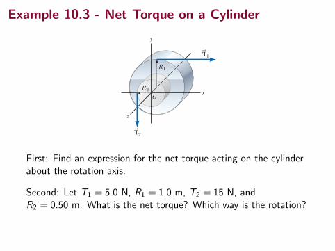
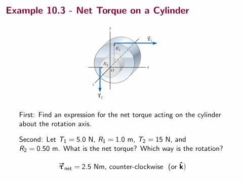
Example 10.3 - Net Torque on a Cylinder
10.4 Torque 301
Pitfall Prevention 10.4Torque Depends on Your Choice of Axis There is no unique value of the torque on an object. Its value depends on your choice of rotation axis.
O
d2
d1
F2S
F1S
Figure 10.8 The force FS
1 tends to rotate the object counterclock-wise about an axis through O, and FS
2 tends to rotate it clockwise.
force FS
acts at an angle f to the horizontal. We define the magnitude of the torque associated with the force F
S around the axis passing through O by the expression
t ; rF sin f 5 Fd (10.14)
where r is the distance between the rotation axis and the point of application of FS
, and d is the perpendicular distance from the rotation axis to the line of action of FS
. (The line of action of a force is an imaginary line extending out both ends of the vector representing the force. The dashed line extending from the tail of F
S in Fig.
10.7 is part of the line of action of FS
.) From the right triangle in Figure 10.7 that has the wrench as its hypotenuse, we see that d 5 r sin f. The quantity d is called the moment arm (or lever arm) of F
S.
In Figure 10.7, the only component of FS
that tends to cause rotation of the wrench around an axis through O is F sin f, the component perpendicular to a line drawn from the rotation axis to the point of application of the force. The hori-zontal component F cos f, because its line of action passes through O, has no ten-dency to produce rotation about an axis passing through O. From the definition of torque, the rotating tendency increases as F increases and as d increases, which explains why it is easier to rotate a door if we push at the doorknob rather than at a point close to the hinges. We also want to apply our push as closely perpendicular to the door as we can so that f is close to 908. Pushing sideways on the doorknob (f 5 0) will not cause the door to rotate. If two or more forces act on a rigid object as in Figure 10.8, each tends to pro-duce rotation about the axis through O. In this example, F
S2 tends to rotate the
object clockwise and FS
1 tends to rotate it counterclockwise. We use the convention that the sign of the torque resulting from a force is positive if the turning tendency of the force is counterclockwise and negative if the turning tendency is clockwise. For Example, in Figure 10.8, the torque resulting from F
S1, which has a moment arm
d1, is positive and equal to 1F1d1; the torque from FS
2 is negative and equal to 2F2d2. Hence, the net torque about an axis through O is
o t 5 t1 1 t2 5 F1d1 2 F2d2
Torque should not be confused with force. Forces can cause a change in transla-tional motion as described by Newton’s second law. Forces can also cause a change in rotational motion, but the effectiveness of the forces in causing this change depends on both the magnitudes of the forces and the moment arms of the forces, in the combination we call torque. Torque has units of force times length—newton meters (N ? m) in SI units—and should be reported in these units. Do not confuse torque and work, which have the same units but are very different concepts.
Q uick Quiz 10.4 (i) If you are trying to loosen a stubborn screw from a piece of wood with a screwdriver and fail, should you find a screwdriver for which the handle is (a) longer or (b) fatter? (ii) If you are trying to loosen a stubborn bolt from a piece of metal with a wrench and fail, should you find a wrench for which the handle is (a) longer or (b) fatter?
�W Moment arm
Example 10.3 The Net Torque on a Cylinder
A one-piece cylinder is shaped as shown in Figure 10.9, with a core section protrud-ing from the larger drum. The cylinder is free to rotate about the central z axis shown in the drawing. A rope wrapped around the drum, which has radius R1, exerts a force T
S1 to the right on the cylinder. A rope wrapped around the core,
which has radius R2, exerts a force TS
2 downward on the cylinder.
(A) What is the net torque acting on the cylinder about the rotation axis (which is the z axis in Fig. 10.9)?
z
x
y
R 1
R 2
O
T1S
T2S
Figure 10.9 (Example 10.3) A solid cylinder pivoted about the z axis through O. The moment arm of T
S1 is
R1, and the moment arm of TS
2 is R2.continuedFirst: Find an expression for the net torque acting on the cylinderabout the rotation axis.
Second: Let T1 = 5.0 N, R1 = 1.0 m, T2 = 15 N, andR2 = 0.50 m. What is the net torque? Which way is the rotation?
#»τ net = 2.5 Nm, counter-clockwise (or k)
Summary
• rotation
• rotational kinematics
• torque
3rd Assignment will be posted later today, watch for anemail.
(Uncollected) Homework Serway & Jewett,
• Read ahead in Chapter 10.
• prev: Ch 10, onward from page 288. Probs: 3, 7, 11, 15, 17,19, 21, 25
• new: Ch 10, Probs: 27 (net torque)