on the polymeric foams: modeling and properties
TRANSCRIPT
REVIEW
On the polymeric foams: modeling and properties
Vivek Srivastava • Rajeev Srivastava
Received: 30 September 2013 / Accepted: 16 December 2013 / Published online: 3 January 2014
� Springer Science+Business Media New York 2013
Abstract Polymeric foams are now widely used and
researched. The physical properties of polymeric foam can
be related to a set of independent structural parameters or
variables of the foam. Study of these variables and corre-
lation with commercial FE packages is essential for reliable
and faster product development. Some aspects of foam
behavior are widely studied while some are little less, like
correlation of physical unloading behavior. For example, a
lot of work in the area of phenomenological constitutive
modeling of uniaxial loading was done, though research in
areas of unloading–reloading and their correlation still
demands more attention. Increasing number of OEMs and
suppliers are moving to computer simulations in the design
phase to assess their future products. Hence, different
parameters within FE packages play a significant role and
also affect the results. Appropriate use of these parameters
will narrow down error band and automatically reduce the
cycle time and development cost. This brief review is
expected to set the perspective for major research work
done so far in terms of FE modeling correlation and con-
stitutive modeling of polymeric foam vis-a-vis to its
properties.
Introduction
Extensive research work is available for characterization of
metals and alloys while a lot of work is under progress in
the area of polymeric foams. Properties of polymeric foams
are complex and require static and dynamic tests for better
representation. The trend of replacing metal and their
alloys with polymers or plastics in most products is rapidly
increasing. For example, Iron and Steel formed 70 % of
gross average weight of automotive vehicle in 1990, while
it was reduced to 65 % in 2000 and further to 61 % in 2011
[1]. Hence, we can conclude a 9 % decline in Iron and
Steel usage, which is compensated by alterative materials,
largely, plastics. Polymeric foam family is composed of
different materials and their types; therefore, we shall
review the development within the following heads for
better presentation of the subject matter:
A. Mechanical properties and governing parameters
B. Polymeric foam modeling
C. FE modeling of foam deformation
D. Conclusion
Mechanical properties and governing parameters
The important characteristics of polymeric foams are
resilience, lightweightedness, stiffness, high porosity, high
crushability, and good energy absorption capacity [2].
Foam material used for packaging and automobile padding
applications is mainly subjected to compressive loads.
Polymeric foam possesses unique physical, mechanical,
and thermal properties, which can be attributed to polymer
matrix. This matrix is formed by cellular structure and gas
composition while its properties are dependent on the
ingredients and their scattering. Properties of gaseous
mixtures are predominantly governed by volumetric char-
acteristics of constituents. Thermodynamic properties, such
as specific heat, equilibrium constant, etc., are governed by
the molecular weight of individual participating compo-
nents [3]. Mechanical properties of foams are broadly
V. Srivastava (&) � R. Srivastava
Department of Mechanical Engineering, Motilal Nehru National
Institute of Technology, Allahabad 211 004, India
e-mail: [email protected]
123
J Mater Sci (2014) 49:2681–2692
DOI 10.1007/s10853-013-7974-5

controlled by the gas pressure, base material properties,
cell geometry, and manufacturing methods. Foams can be
differentiated as open-cell foam and closed-cell foam,
based on cell type, as shown in Fig. 1. Structure–property
relationship is discussed in the following two sections:
a Modulus and effect of foam density
b Geometrical constitution of foam and its effect
Modulus and effect of foam density
Like any other design parameter, foam density also needs
to be optimized as per the targeted application. Gibson and
Ashby [4] explained that at lower density, densification
zone is reached quickly which results in very high force
prior to full energy dissipation. On the other hand, in case
of high-density foam, force exceeds the critical value way
before adequate energy absorption, resulting in partially
utilized compressive strains. Higher density foams of the
same type experience higher permanent deformation,
whereas compression stresses are lower than that of the
indentation stresses. This behavior suggests the role of
shear and tensile strength in providing additional resistance
to the deformation [5].
Internal structure plays a vital role in defining foam’s
mechanical properties. For any given amount of energy, low-
density foam sustains a large deformation due to the quick
densification and low value of plateau. On the other hand,
high-density foam sustains low deformation for the same
amount of energy [6], which clearly points that ideal foam
should be of intermediate density. Young’s Modulus and yield
stress follow power law dependence with respect to density of
foam shown in Eq. (1). Density exponent is found to be 1.5 and
4 for yield stress and Young’s Modulus, respectively, though
bulk modulus varies linearly with density [7–9]
E ¼ ðqÞn; ð1Þ
where E, q, and n are the modulus, density, and density
exponent of foam. It is well established that yield is controlled
by the maximum principal stress for polystyrene and
polyurethane foams [10, 11]. Effect of density, filler size,
impregnation, cell structure, cell orientation, testing
temperature, and crush behavior has been studied in detail
[12–21]. Constitutive and yield behavior of polyvinylchloride,
along with tensile, shear and compression, and multiaxial yield
response has also been described [22, 23]. Polymeric foams
have always exhibited lower values of maximum force when
compared with solid material block of the same material [6].
At higher strains, even at 80 %, stress increases very rapidly.
At strains as high as 95 %, foam density is not equal to that
of solid foam (polystyrene) and becomes very stiff beyond
2.5 MN m-2 [24]. Higher density foams have higher yield
strength, breaking strength, and Young’s modulus, where
stress and strain follow a linear relationship within the range
of 20 % of tensile strain. Resilient foams can sustain strains
up to 50 % before fracture, while crushable foams can take
only 20 % strain before fracture [5]. In most of the cases,
dynamic stress levels were higher than their static
counterpart at the same strain level. Foams can absorb
more energy in dynamic loading. DYTHERM foam, with
unit volume of 48.08 kg m-3, resulted in 31 % difference in
energy absorption during dynamic and static compression
[5]. At larger compressions, compressive response is
considerably different for similar density foams
(polyethylene), when there is substantial variation in cell
size [25]. Gibson and Ashby [26, 27] derived the modulus of
a closed-cell foam which contained three terms that reflect
the effect of strut bending, membrane (cell face) stretching
[28, 29], and the internal gas pressure of closed cells. The
stiffness of closed-cell foam can be attributed to these three
contributions as in Eq. (2).
E�
Es
� /2 q�
qs
� �2
þ 1� /ð Þ q�
qs
þ qo
Es
� �1� 2t�ð Þ
1� q�
qs
� � ; ð2Þ
Fig. 1 Open-cell and closed-cell foam
2682 J Mater Sci (2014) 49:2681–2692
123
where E* and Es are the modulus of foam and solid
polymer, respectively; q* and qs are the density of foam
and solid polymer; and n is the density exponent. On the
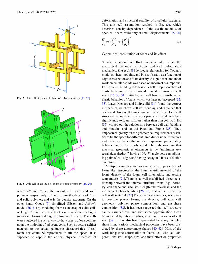
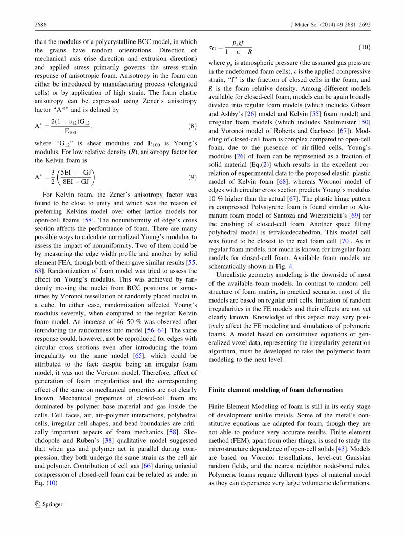
other hand, Goods [7] simplified Gibson and Ashby’s
model [26, 27] by modeling foam as an array of cubic cells
of length ‘‘l, and struts of thickness t, as shown in Fig. 2
(open-cell foam) and Fig. 3 (closed-cell foam). The cells
were staggered in such a way so that corners of one cell rest
upon the midpoint of adjacent cells. Such structure neither
matched to the actual geometric characteristics of real
foam nor could be reproduced to fill the space. It is
supposed to capture the critical physical processes of
deformation and structural stability of a cellular structure.
This unit cell assumption resulted in Eq. (3), which
describes density dependence of the elastic modulus of
open-cell foam, valid only at small displacements [25, 26]
E�
Es
� t4
l4
� �� q�
qs
� �2
ð3Þ
Geometrical constitution of foam and its effect
Substantial amount of effort has been put to relate the
mechanical response of foams and cell deformation
mechanics. Zhu et al. [8] derived a relationship for Young’s
modulus, shear modulus, and Poisson’s ratio as a function of
edge cross section and foam density. A significant amount of
work on cellular solids was based on incorrect assumptions.
For instance, bending stiffness is a better representative of
elastic behavior of foams instead of axial extensions of cell
walls [26, 30, 31]. Initially, cell wall bent was attributed to
elastic behavior of foams which was later not accepted [32,
33]. Later, Menges and Knipschild [34] found the correct
mechanism, which was cell wall bending, and explained that
open- and closed-cell foams have similar stiffness. Cell wall
struts are responsible for a major part of load and contribute
significantly to foam stiffness rather than thin cell wall. Ko
[35] worked out the relationship between cell wall bending
and modulus and so did Patel and Finnie [28]. They
emphasized greatly on the geometrical requirements essen-
tial to fill the space for different three-dimensional structures
and further explained that on foam expansion, participating
bubbles tend to form polyhedral. The only structure that
meets all geometric requirements is the ‘‘minimum area
tetrakaidecahedron’’ having 109.47� angle between adjoin-
ing pairs of cell edges and having hexagonal faces of double
curvature.
Multiple variables are known to affect properties of
foam like: structure of the foam, matrix material of the
foam, density of the foam, cell orientation, and testing
temperature [21].There is a well-established direct rela-
tionship between the internal structural traits (e.g., poros-
ity, cell shape and size, strut length and thickness) and the
mechanical characteristics [26, 36] that are governed by
cell wall material [37].The structural variables, necessary
to describe plastic foams, are density, cell size, cell
geometry, polymer phase composition, and gas-phase
composition [38]. It has been suggested that cell structure
can be assumed oval and with some approximation it can
be modeled by ratio of radius, area, and thickness of cell
wall [39]. It has also been represented by many complex
shapes, and various mechanical properties have been pre-
dicted by these approximate shapes [40–42]. Most of the
work for plastic deformation of foams deal with cell cor-
poreal like strut shape, size, and their effect on properties
Fig. 2 Unit cell of open-cell foam of cubic symmetry [25, 26]
Fig. 3 Unit cell of closed-cell foam of cubic symmetry [25, 26]
J Mater Sci (2014) 49:2681–2692 2683
123

of periodic arrangement of cells, isotropy (effect of disor-
der), and cellular interaction at microscopic scale [43].
Most of the foam material is distributed, either in cell walls
or cell ribs, and affects compression behavior of cellular
foam. Energy dissipation mechanism is likely through cell
bending, buckling, or fracture, but stress is generally lim-
ited by the long and flat plateau of the stress–strain curve
38]. Properties of foam are closely linked to its structural
parameters. Berlin and Shutov [44] listed the following
important parameters affecting the properties of foam:
I. Relative number of open cells
II. Relative foam density
III. Cell size
IV. Cell shape or geometrical anisotropy
V. Cell walls thickness and distribution of solid between
struts and faces
VI. Geometry of a foam cell and its constituents
Relative number of open cells
Practically, foams are a mix of open-cell and closed-cell
matrix and it is obvious that the relative content of open
cells in closed-cell foam governs the resultant physical
behavior of cellular materials. In a study [45] of closed-cell
PUR foam, cell walls are classified as closed, pin holes,
partially open (less than 50 % open), and open. The
effective fraction of open cells is estimated, then, by the
Eq. (4) as under:
t ¼Nopen þ 1
2
� Npart
Nopen þ Npart þ Npin þ Nclosed
; ð4Þ
where ‘‘N’’ corresponds to the number of walls of various
classes.
Relative foam density
Relative foam density qf=qsð Þ defines many mechanical
properties by an empirical relation as in Eq. (5)
Uf
Us
¼ Cqf
qs
� �p
; ð5Þ
where Uf and Us are mechanical properties of foam and
solid phase; correspondingly, C and p are the coefficients
obtained from the experiments. From Gibson and Ashby’s
model [26, 27], Goods et al. [7] gave a simplified relation
of relative density with cell dimensions as in Eq. (6).
q�
qs
/ V�
Vc
/ t
l
� �2
ð6Þ
Also, from Eq. (2) for U ¼ 1 (open-cell foam), negli-
gible gas pressure, small qo, and high relative density,
modulus was found to be varying as the square of the
density; while at low relative densities, the modulus was
linearly dependent on the density.
Cell size
Due to irregular cell structure and variation in size, it has
been observed that during compression, extruded foam
does not yield uniformly [46, 47]. Cell size is a critical
parameter in identification of foam properties, though the
base material may change the behavior completely. For
example, cell size is not a governing parameter for
Young’s modulus [48], whereas increasing cell size makes
closed-cell foam stiffer [45]. Foam tends to align as per the
extrusion direction during compression [49]; and, on the
other hand, microscopic inspection reveals a uniform cell
distribution and orientation for all the examined material
and this infers that mechanical behavior is independent of
the direction of the loading [6].
Cell shape or geometrical anisotropy
Foam properties are direction dependent and mostly
depend on the manufacturing process. Based on this pro-
duction process, mostly three main directions have been
determined in foam with different cell dimensions in these
directions. Mechanical characteristics of foam were found
better in the directions where foam cells have greater
dimensions [50].
Cell walls thickness and distribution of solid between struts
and faces
Major portion of base material was supposed to be found in
walls, struts, and vertices of the cell. It is assumed that the
solid-phase material is contained by walls/struts and struts,
respectively, for closed-cell foam and open-cell foam. The
presence of material in the vertices is assumed negligible
and can be ignored [50].
Geometry of a foam cell and its constituents
Vladimir [50] has compiled the following set of conditions
for foam to be in equilibrium:
• A strut is an intersection of three walls (Plateau’s law
[51]).
• A knot point is an intersection of 4 struts and an
intersection of 6 walls (Plateau’s law [51]).
• Struts are straight in the undeformed state.
• Several struts, belonging to the same cell wall and
connected to each other, lie in one plane.
2684 J Mater Sci (2014) 49:2681–2692
123

• As a result of the above points, walls are flat in
undeformed state.
• During the production process of foam (growing), a
dihedral angle (angle between faces) is equal to 120�.
• Struts intersect in a vertex under the bond angle equal
to 109�2801600.• These laws are based on the principles of the
minimizing surface energy during foam growth.
Cell wall thickness is neither constant nor uniform
within the wall and the same is also applicable for the struts
as well. They can vary, and distribution of the wall thick-
ness and strut cross section may be large and nonuniform.
The use of mean values in the modeling can lead to the
introduction of errors. That is why it is important to mea-
sure a considerable amount of struts and walls and to pay
attention onto the distributions. Foams are found to be very
sensitive to strain rate during loading; therefore, static tests
are of partial use in forecasting cushion performance [52].
During compression, the cells of extruded foam do not
yield uniformly due to cell size and shape variations [47].
Hysteresis caused by strain rate leads to conversion of part
of kinetic energy into heat energy during cyclic loading and
unloading of closed-cell cushions [53]. Orientation of the
cushion during compression has significant bearing due to
affinity of cells getting aligned during extrusion [49]. Two-
parameter Mooney–Rivlin strain energy potential model
describes the hyperelasticity of the solid foam [54]. Ini-
tially, for the strain less than 0.05, cell wall bending
dominates and foam deformation was found to be primarily
in linear elastic region [5]. Very little energy was absorbed
in the linear elastic region. After cell wall bending, cell
edges or walls were formed due to elastic buckling of
plates. This stage was generally characterized as a plateau
of deformation at almost constant stress ,and long plateau
of the stress–strain curve is the cause of large energy
absorption at almost constant load [6].
Despite large amount of research work in the area of
geometric visualization and parameterization, nothing
substantial has been achieved in terms of contribution and
modeling of geometric constitution of polymeric foam.
This is due to some basic flaws in the approach like
adaptation of previous mathematical models relying on
static test data for development of material models for
essentially a rate-dependent material, and ignoring the
error creeping into the model due to averaging of highly
random material structure.
Polymeric foam modeling
Micromechanics of foam is different for open- and closed-
cell foam. Gibson and Ashby [4, 26, 27] derived Eq. (2) for
closed-cell foam and the same is applicable to open-cell
foam when U ¼ 1. The differentiating factor between these
two is the absence of the membrane in the open-cell foam.
In most of the cases, constitutive foam structure consists of
closed as well as open cells. In practice, it is difficult to
make foam only with closed or only with open cells. Open-
cell foams contain mostly open cells (more than 90 %) and
vice versa.
For open-cell foams, existing micromechanics models
can be broadly classified as regular models (which include
Gibson and Ashby [26] model and Kelvin [55] model),
and irregular models (which include Van der Burg et al.
[56] model and Zhu’s Voronoi tessellation model [57]).
However, they were only building blocks and none of
them was the actual representation of the physical phe-
nomenon. The important aspects of polymeric foam’s
mechanics are uniform/nonuniform edge, polyhedral cells
(with uniform edges), full edge and vertex geometry,
irregular cell shapes, anisotropic cell shapes, and variable
cell sizes [58]. Manufacturing parameters, such as rise
direction and blowing agents, play a greater role in the
mechanics of the foam. Foam compression in rise direc-
tion displays higher force compared to the compression
perpendicular to rise direction. This behavior was
observed till 20 % of strain and afterward, force rose
monotonically for compression, perpendicular to rise
direction. This force rose rapidly when the strain exceeds
50 % and edges touched [59, 60]. Open-cell foams have
slender edges with Plateau border cross sections [58]. In
this case, variation in bending and torsional stiffness due
to variation in width along the edge should be considered,
while most of the models assumed edges of constant
width for simplification of analysis. Dement’ev and Ta-
rakanov [61] calculated Young’s modulus of the Kelvin
foam for the [001] compression direction which is rep-
resented below in Eq. (7).
E100 ¼ffiffiffi2p
EP
b=Lð Þ4
2þ b=L; ð7Þ
where E100 is the polymer Young’s modulus, b is the
breadth of the edges with a square cross section, and ‘‘L’’ is
their length. The denominator contains a correction for the
vertex volume. Zhu et al. [8] examined the prediction of
tensile and compressive Young’s Modulus E100 of BCC
lattice of tetrakaidecahedral cells [61] and found erroneous
compressive results. Isotropy of foam could be not justified
due to the lack of computation of shear modulus and not
taking account of torsional edge deformation mechanism.
Assumption of uniform stress and uniform strain results in
lower average modulus and higher average results,
respectively. The predicted Young’s modulus of the
Warren and Kraynik [62] model is about 50 % higher
J Mater Sci (2014) 49:2681–2692 2685
123
than the modulus of a polycrystalline BCC model, in which
the grains have random orientations. Direction of
mechanical axis (rise direction and extrusion direction)
and applied stress primarily governs the stress–strain
response of anisotropic foam. Anisotropy in the foam can
either be introduced by manufacturing process (elongated
cells) or by application of high strain. The foam elastic
anisotropy can be expressed using Zener’s anisotropy
factor ‘‘A*’’ and is defined by
A� ¼ 2 1þ t12ð ÞG12
E100
; ð8Þ
where ‘‘G12’’ is shear modulus and E100 is Young’s
modulus. For low relative density (R), anisotropy factor for
the Kelvin foam is
A� ¼ 3
2
5EI þ GJ
8EI + GJ
� �ð9Þ
For Kelvin foam, the Zener’s anisotropy factor was
found to be close to unity and which was the reason of
preferring Kelvins model over other lattice models for
open-cell foams [58]. The nonuniformity of edge’s cross
section affects the performance of foam. There are many
possible ways to calculate normalized Young’s modulus to
assess the impact of nonuniformity. Two of them could be
by measuring the edge width profile and another by solid
element FEA, though both of them gave similar results [55,
63]. Randomization of foam model was tried to assess the
effect on Young’s modulus. This was achieved by ran-
domly moving the nuclei from BCC positions or some-
times by Voronoi tessellation of randomly placed nuclei in
a cube. In either case, randomization affected Young’s
modulus severely, when compared to the regular Kelvin
foam model. An increase of 46–50 % was observed after
introducing the randomness into model [56–64]. The same
response could, however, not be reproduced for edges with
circular cross sections even after introducing the foam
irregularity on the same model [65], which could be
attributed to the fact: despite being an irregular foam
model, it was not the Voronoi model. Therefore, effect of
generation of foam irregularities and the corresponding
effect of the same on mechanical properties are not clearly
known. Mechanical properties of closed-cell foam are
dominated by polymer base material and gas inside the
cells. Cell faces, air, air–polymer interactions, polyhedral
cells, irregular cell shapes, and bead boundaries are criti-
cally important aspects of foam mechanics [58]. Sko-
chdopole and Ruben’s [38] qualitative model suggested
that when gas and polymer act in parallel during com-
pression, they both undergo the same strain as the cell air
and polymer. Contribution of cell gas [66] during uniaxial
compression of closed-cell foam can be related as under in
Eq. (10)
rG ¼paef
1� e� R; ð10Þ
where pa is atmospheric pressure (the assumed gas pressure
in the undeformed foam cells), e is the applied compressive
strain, ‘‘f’’ is the fraction of closed cells in the foam, and
R is the foam relative density. Among different models
available for closed-cell foam, models can be again broadly
divided into regular foam models (which includes Gibson
and Ashby’s [26] model and Kelvin [55] foam model) and
irregular foam models (which includes Shulmeister [50]
and Voronoi model of Roberts and Garboczi [67]). Mod-
eling of closed-cell foam is complex compared to open-cell
foam, due to the presence of air-filled cells. Young’s
modulus [26] of foam can be represented as a fraction of
solid material [Eq.(2)] which results in the excellent cor-
relation of experimental data to the proposed elastic–plastic
model of Kelvin foam [68]; whereas Voronoi model of
edges with circular cross section predicts Young’s modulus
10 % higher than the actual [67]. The plastic hinge pattern
in compressed Polystyrene foam is found similar to Alu-
minum foam model of Santoza and Wierzibicki’s [69] for
the crushing of closed-cell foam. Another space filling
polyhedral model is tetrakaidecahedron. This model cell
was found to be closest to the real foam cell [70]. As in
regular foam models, not much is known for irregular foam
models for closed-cell foam. Available foam models are
schematically shown in Fig. 4.
Unrealistic geometry modeling is the downside of most
of the available foam models. In contrast to random cell
structure of foam matrix, in practical scenario, most of the
models are based on regular unit cells. Initiation of random
irregularities in the FE models and their effects are not yet
clearly known. Knowledge of this aspect may very posi-
tively affect the FE modeling and simulations of polymeric
foams. A model based on constitutive equations or gen-
eralized voxel data, representing the irregularity generation
algorithm, must be developed to take the polymeric foam
modeling to the next level.
Finite element modeling of foam deformation
Finite Element Modeling of foam is still in its early stage
of development unlike metals. Some of the metal’s con-
stitutive equations are adapted for foam, though they are
not able to produce very accurate results. Finite element
method (FEM), apart from other things, is used to study the
microstructure dependence of open-cell solids [43]. Models
are based on Voronoi tessellations, level-cut Gaussian
random fields, and the nearest neighbor node-bond rules.
Polymeric foams require different types of material model
as they can experience very large volumetric deformations.
2686 J Mater Sci (2014) 49:2681–2692
123

Ongoing practice is to superimpose stress–strain history on
phenomenological model, which is completely tabulated
input instead of parametric input.
Rusch [66] gave a shape function for empirical curve fit
of uniaxial compression stress ‘‘r’’ versus strain ‘‘e’’ data,
using Eq. (11). Also, strain softening of cellular materials
deformation was to be found occurring in confined regions/
bands. These bands show discontinuity due to a sudden
change in amount of deformation [71, 72].
FðeÞ � rEe¼ aep þ beq; ð11Þ
where ‘‘E’’ is the Young’s modulus and ‘‘a,’’ ‘‘b,’’ ‘‘p,’’
‘‘q’’ are constants. These five independent constants are
found to be sufficient to make a reasonable fit to most data.
The curve-fitting parameters are not found linked to
deformation mechanisms, so cannot be compared with
foam microstructural variables. It is not clear that how
some foam material models in LS-DYNA, which use curve
fitting, predict the foam response under complex strain
states. Commercial softwares like LS-Dyna, RADIOS and
PAM-CRASH do not disclose much about how their
material model functions. Various material models avail-
able for foam within LS-DYNA are listed in Table 1.
There are many ways to obtain test data of materials.
Impact tester, Hopkinson bar system, conventional screw
drive load frame, servo-hydraulic system, and high-rate
servo-hydraulic system are the five testing systems mostly
used to obtain rate-dependent material data [73]. Under
impact, stress state of foam was found to be dominated by
compression and shear [74]. Polymeric foams have very
high strain rate dependency when compared to solid
metallic materials [6], which is primarily due to intrinsic
mechanical characteristics of material. The presence of
fluid (air) also adds to this behavior. Foam deformation
causes inside air compression, which results in air pushing
the cell walls. Fluid flow is found to be essentially affected
by compression rate; hence, the compression behavior is an
important aspect of foam properties. Uniaxial compression,
uniaxial tension, and simple shear tests are the primary
tests, which help understand mechanical properties of
foam. These tests have provided interesting insights about
fracture of foams and two-dimensional response of crush-
able foam under low velocity impact [72, 75]. Some rep-
resentative data/parameters are tabulated in Table 2.
Dynamic tests characterize dynamic behavior and energy
absorption capabilities of foams. Several models and
experimental methods were developed for hydrostatic
compression of foam to study the foam behavior in
numerical simulations [76–78]. Mechanical characteristics
of foams are widely governed by temperature as well.
Uniaxial compression test with varying temperature in the
range of -20 to 80 �C resulted in a considerable decrease
of compressive stress with increase in temperature [79, 80].
An accurate constitutive model, representing true stress–
strain behavior, is the prerequisite for better correlation of
simulations. The actual deformation is molecular structure
dependent and guided by polymer processing. As per the
available literature, elastic plastic theory-based foam mate-
rial model was developed by Kreig [81] in 1972 for Sandia
National laboratories. This study was originally meant for
soil and concrete though it was majorly used for foams under
compression loadings due to similarity in uniaxial com-
pressive stress–strain nature. Kreig model included strain
Foam Models
Open Cell Foam
Regular Model
Kelvin's Model
[55]
Gibson & Ashby Model
[26]
Irregular Model
Vander Burg
Model
[56]
Zhu's V. Tessellation Model
[57]
Closed Cell Foam
Regular Model
Gibson & Ashby Model
[26]
Kelvin's Model
[55]
Irregular Model
Roberts-Garboczi
Model
[67]
Shulmeister
Model
[50]
Fig. 4 Schematic representation of available foam models
J Mater Sci (2014) 49:2681–2692 2687
123

Table 1 Available foam material models for LS- Dyna [94]
MAT
No
Keyword Strain
rate
Fail THERM ANISO DAM TENS
05 MAT_SOIL_AND_FOAM Y
14 MAT_SOIL_AND_FOAM_FAILURE Y Y
38 MAT_BLATZ_KO_FOAM
53 MAT_CLOSED_CELL_FOAM
57 MAT_LOW_DENSITY_FOAM Y Y Y
62 MAT_VISCOUS_FOAM Y
63 MAT_CRUSHABLE_FOAM Y
73 MAT_LOW_DENSITY_VISCOUS_FOAM Y Y Y
75 MAT_BILKHU/DUBIOS_FOAM Y
83 MAT_FU-CHANG_FOAM Y Y Y Y
142 MAT_TRANSVERSLEY_ANISOTROPIC_CRUSHABLE_FOAM Y Y
144 MAT_PITZER_CRUSHABLE_FOAM Y Y
154 MAT_DESHPANDE_FLECK_FOAM Y
163 MAT_MODIFIED_CRUSHABLE_FOAM Y Y
177 MAT_HILL_FOAM Y
178 MAT_VISCOELASTIC_HILL_FOAM Y Y
179 MAT_LOW_DENSITY_SYNTETIC_FOAM Y Y Y Y Y Y
180 MAT_LOW_DENSITY_SYNTETIC_FOAM_ORTHO Y Y Y Y Y
181
183
MAT_SIMPLIFIED_RUBBER/FOAM_(WITH_FAILURE)/
_WITH_DAMAGE
Y Y Y Y
Table 2 Compilation of representative physical test parameters of foam block
Foam block
dimension
Minimum strain
rate
Pressure Shape Densities
studied
(g L-1)
Foam Test type Articles
Maximum strain
rate
Drop tower
height
Initial velocity
25.4 9 Ø19.4 1.7 9 10-5 s-1 – Cylinder 120–610 PU Tension [7]
50.8 9 Ø28.7 1.7 9 10-2 s-1 Compression
50.8 9 Ø28.7 Impact
142.24 9 Ø69.3 – 6.8-213.7 kPa Cylinder 32–80 PU Hydrostatic
triaxial
[83]
152.4 9 152.4 9 50.8 – Rectangular
block
30–35 EPP Drop tower
impact
[52]
609.6–914.4 mm
100 9 100 9 50 0.14 s-1 – Rectangular
block
65–94 PU Compression [105]
14 s-1
50 9 50 9 50 1.6 9 10-3 – Rectangular
block
3.0–9.6 PP,PS,PU Compression [106]
Tension
88 s-1 Hydrostatic
Shear
127 9 127 9 50.8 – Multiple
parameters
Rectangular
block
20–63 PU,EPP Compression [5]
Tension
Indentation4.47 mm msec-1
50 9 50 9 50 0.02 s-1 – Rectangular
block
31–100 EPP,PUR,NORYL Compression [6]
2688 J Mater Sci (2014) 49:2681–2692
123
rate in constitutive equations. This model could, however,
not resolve the issue of coupling of longitudinal loading and
transverse deformation. In continuation of development,
linear elastic constitutive model accurately defined the foam
behavior in the linear elastic region [82]. Further, Neilsen
et al. [83] suggested an improved model, focusing on post-
yield behavior, which incorporated volumetric and devia-
toric part of foam behavior.
Most of the commercial softwares are built-in with foam
material models like ABAQUS Hyperfoam, Crushable
Foam Plasticity Model and for LS-DYNA, MATL 57 (Low
Density Foam), MATL 83 (Fu Chang Foam), and PAM-
CRASH material model 21. These models are based on the
assumption that strain energy function can be determined
by principal stretches with respect to the homogeneous
stress-free natural state [84]. The strain energy density [85]
of the Hyperfoam model is expressed by Eq. (12).
U ¼XN
i¼1
2li
a2i
½kai
1 þ kai
2 þ kai
3 � 3 þ ððJelÞ�aibi � 1Þ�; ð12Þ
where U is the strain energy density and N, li, ai, and ‘‘bi’’
are material parameters. Earlier in the development of
constitutive equations three types of models, viz (1) Uni-
axial crush model, (2) Conventional deviatoric plasticity
model, and (3) Soils model which combines volumetric
plasticity with pressure-dependent deviatoric plasticity,
have been mostly used to model the foam behavior [86].
Although, these three models are not able to accurately
represent the actual physical behavior. Various empirical
nonlinear stress–strain relations exist to describe foam
material characteristics under static loading. All these
models and empirical constitutive equations are found
valid only for uniaxial compression [87–90]. All these
models were without strain effect which was a major
shortcoming; though later, Sherwood and Frost [79] pro-
posed an empirical equation, containing strain rate effect.
This model was applicable only to uniaxial compression
loading and deformation and hence was not suitable for
3-D real world scenarios like crash loadings. Unified
equations are a better representation when compared to
constitutive equations which model the viscoplasticity
behavior. These are the ‘‘unified’’ set of constitutive
equations without a yield criterion or loading/unloading
conditions. All aspects of inelastic deformation, including
plasticity, creep, and stress relaxation, are represented by a
single inelastic strain rate term [91]. Fu Chang et al. [92]
added another nonlinear term in unified equations to
emulate bottoming out of the foam. Most of the foams have
random internal cell structure while most of the available
material models are based on the hypothesis of idealized
unit cell structure and, hence, are not able to reflect the
actual mechanical response of the foam [68]. 2-D models
with circular cells in random fashion were used to under-
stand static (uniaxial tension, compression, and pure shear)
and dynamic performance of foam [93]. Circular cell
model consisting of two-dimensional regular and random
cells used to simulate the microstructure of polymer foams.
This method coupled with FEM when simulated large
deformation of foam resulted in very little strain rate sen-
sitivity. This was essentially due to rate-independent con-
stitutive model [54]. Appropriate material model within FE
package is an essential requirement for better correlation.
For example, material type 57 in LS-DYNA- 3D [94] is
suitable for static loading while MAT 83 is good for rate-
sensitive dynamic analysis [5, 95]. This conclusion also
suggested the need for selecting the appropriate material
models for simulating static and dynamic impact problems.
Conclusion
Organized approach is required to properly understand the
polymeric foams. Most of the work done was adapted for
foam without considering the finer implications on the
property and modeling of polymeric foams. A lot of work
done on honeycomb-like materials is replicated for poly-
meric foams. Honeycomb has a periodic structure and
similar models are developed for foam assuming periodic
properties for idealized unit cell though that is not the case,
foams are mostly very random in structural arrangements
[96]. Many empirical structural property equations,
including foam density and property equations, were
developed based on physics, chemistry, and processing
conditions relationship [97–99]. There is a low volume of
work relating microstructure with macroscopic physical
properties and there are few good structure characterization
methods available [100]. Most of the models are based on
assumptions like monodispersity, rhombic dodecahedral
[101] cell shapes, tetrahedral cell intersections, and Pla-
teau’s laws [9, 30, 35, 51, 98]; and later simplified foam
shape is described using cubic unit cells to represent foam
behavior [7]. These relationship models result in fair
engineering correlation, though these are the generic
models which may not represent polymeric foam [100].
Product design requires repetitive numerical simulation
using finite element program such as LS-DYNA3D [94] for
cost-effective product evaluation. However, Finite element
analysis and material modeling correlations always have
their limitations in terms of fundamental assumptions; for
example, volume and density as volume changes during the
testing, which ideally should be constant, and elastic wave
velocity depends on density which again does not remain
constant along with oscillation issues in test setups and use
of numerical filters. It is necessary to study the
J Mater Sci (2014) 49:2681–2692 2689
123

performance of such material under dynamic loadings. Lots
of experiments were performed on polymer foams to
characterize mechanical properties, whereas few numerical
investigation studies are carried out [102]. Even the
existing numerical studies further required fine tuning in
terms of input parameters. The current worth of the global
polymer foams market is $ 82.6 billion and is estimated to
reach $131.1 billion by 2018, growing at a CAGR of 7.7 %
from 2013 to 2018. The high demand across industries such
as automotive, building and construction, and packaging
will increase the overall polymer foam consumption [103].
There is a scope of further research in the area of corre-
lation of physical behavior with finite element results in
general and unloading behavior in particular. Authors have
identified some possible areas of future research as
following:
a) All available constitutive models are found dependent
on processing history and hence not applicable to any
other polymeric foam or the same foam with different
processing parameters. There is an immediate need to
develop such models to incorporate the mentioned
parameters.
b) Modeling of anisotropic and isotropic closed-cell foam
is not very much explored and requires focus to
research further.
c) There is no accurate and correlated algorithm to
generate or imitate randomness in the FE model of
polymeric foam matrix. Development of such models
will deeply help the modeling of polymeric foam.
d) Most of the work available was performed on ABA-
QUS while the industry mostly prefer LS-DYNA,
PAM-CRASH, or RADIOS for similarity of the
platform across different types of product development
and testing. Hence, lot of cross correlation among
softwares is also required for a unified approach.
e) The constitutive and phenomenological models avail-
able are mostly applicable to limited number of
loadings and on top of all, unloading behavior is not
properly incorporated and validated in constitutive
equations and modeling.
f) There is a lot of work done in the area of physical to
FE correlation, yet effect of different parameters on the
same analysis are still unknown. One analysis can be
performed in various ways with different input param-
eters on software platform and have dissimilar results.
For example, authors have conducted a study to
evaluate different material types for polymeric foam
(expanded polypropylene) in LS-DYNA and found that
there was a difference in energy absorption of 27.83 %
for MAT57 and MAT83 for the same analysis [104]. A
standard set of input parameters is required for
integrated product development. Authors are currently
working in developing a structured framework for
polymeric foams within LS-DYNA.
Correlation studies are very common, though it is not
easy to differentiate between the error due to wrong
selection of simulation parameters and error due to
experimental noise. This is largely due to lack of set pro-
cedures for characterization, which may lead to pragmatic
choices rather than the factual scientific decision based on
material and its behavioral characteristics. Future studies
may focus on a DOE-based study of simulation input
parameters for different FE solvers like LS-DYNA,
ABAQUS, PAM-CRASH, and RADIOS. This may further
lead to correlation with physical results and cross correla-
tion among the selected commercial FE solvers for devel-
opment of unified product development approach. The
future work in assessing foam behavior for loading/
unloading/reloading in finite element environment may
provide a deeper insight. This will surely reduce time and
effort in estimating newer designs and predicating the life
use of foam, overcoming the hassles of repeated physical
testing and correlation.
Acknowledgements Authors would like to acknowledge and thank
George Jacob, Deputy Manager, Chrysler Corporation and Anurag
Verma, Principal, Karyon Consulting for material information and
insights. The authors sincerely thank Dr. Anshul Chandra for effective
help in manuscript preparation.
References
1. Swift K (2011) http://www.plastics-car.com/lightvehiclereport
Accessed 12 May 2011
2. Marsavina L and Linul E (2010) Fracture toughness of poly-
urethane foams, Experiments versus micromechanical models.
In : Proc 18th European Conference on Fracture, Germany
3. Lee ST, Park CB, Ramesh NS (2006) Polymeric foams: science
and technology, vol 3. CRC Press, Florida
4. Gibson LJ, Ashby MF (1997) Cellular solids: structures and
properties, 2nd edn. Cambridge University Press, Cambridge
5. Chou CC, Zhao Y, Chai L, Co J, Lim GG, Lin TL (1995)
Development of foam models as applications to vehicle interior,
SAE Technical Paper 952733
6. Avalle M, Belingardi G, Montanini R (2001) Characterization of
polymeric structural foams under compressive impact loading
by means of energy-absorption diagram. Int J Impact Eng
25:455–472
7. Goods SH, Neuschwanger CL, Henderson CC, Skala DM (1998)
Mechanical properties of CRETE, a polyurethane foam. J Appl
Polym Sci 68(7):1045–1055
8. Zhu HX, Knott JF, Mills NJ (1997) Analysis of the elastic
properties of open-cell foams with tetrakaidecahedral cells.
J Mechs Phys Solids 45(3):319–343
9. Warren WE, Kraynik AM (1997) Linear elastic behavior of a
low-density Kelvin foam with open cells. J Appl Mech
64(4):787–794
10. Fortes MA, Fernandes JJ, Serralheiro I, Rosa ME (1989)
Experimental determination of hydrostatic compression versus
volume changes curves for cellular solids. J Test Eval 17:67–71
2690 J Mater Sci (2014) 49:2681–2692
123

11. Shaw MC, Sata T (1966) The plastic behavior of cellular
materials. Int J Mech Sci 8(7):469–478
12. Saint-Michel F, Chazeau L, Cavaille JY, Chabert E (2006)
Mechanical properties of high density polyurethane foams: I.
Effect of the density. Composites Sci Technol 66(15):2700–2708
13. Saint-Michel F, Chazeau L, Cavaille JY (2006) Mechanical
properties of high density polyurethane foams: II effect of the
filler size. Composites Sci Technol 66(15):2709–2718
14. Marsavina L, Sadowski T, Constantinescu DM, Negru R (2009)
Polyurethane foams behaviour. Experiments versus modeling.
Key Eng Mat 399:123–130
15. Marsavina L, Sadowski T, Constantinescu DM, Negru R (2008)
Failure of polyurethane foams under different loading condi-
tions. Key Eng Mat 385:205–208
16. Marsavina L, Sadowski T (2008) Dynamic fracture toughness of
polyurethane foam. Polym Test 27(8):941–944
17. Marsavina L, Sadowski T, Knec M, Negru R (2010) Non-linear
behaviour of foams under static and impact three point bending.
Int J Non-Linear Mech 45(10):969–975
18. Goto A, Yamaguchi K, Hamada H (2003) Influence of geo-
metric shape of void on mechanical properties of polyurethane
foam, Proc ANTEC: 3575–3578
19. Yamaguchi K, Goto A, Hamada H. (2003) Compressive prop-
erties of urethane foam, Symp 8th Japan Int SAMPE: 689–692
20. Li QM, Mines RAW, Birch RS (2000) The crush behaviour of
Rohacell-51WF structural foam. Int J Solids Struct 37(43):
6321–6341
21. Ramsteiner F, Fell N, Forster S (2001) Testing the deformation
behaviour of polymer foams. Polym Test 20(6):661–670
22. Berthelot JM, Lolive E (2002) Non-linear behaviour of foam
cores and sandwich materials, Part 1: materials and modelling.
J Sandw Struct Mat 4(3):219–247
23. Deshpande VS, Fleck NA (2001) Multi-axial yield behaviour of
polymer foams. Acta Mater 49(10):1859–1866
24. Mills NJ and Hwang AMH (1989) The multiple impact per-
formance of high density polyethylene foam, Cell Polym
259–276
25. Kuncir EJ, Wirta RW, Golbranson FL (1990) Load-bearing
characteristics of polyethylene foam: an examination of structural
and compression properties. J Rehabil Res Dev 27(3):229–238
26. Gibson LJ, Ashby MF (1982) The mechanics of three dimen-
sional cellular materials. Proc R Soc Lond A382:43–59
27. Gibson LJ, Ashby MF (1988) Cell solids. Pergamon Press,
Oxford
28. Patel MR, Finnie I (1970) Structural features and mechanical
properties of rigid cellular plastics. J Mat 5(4):909–932
29. Timeshenko S, Young DH (1962) Elements of strength of
materials, 4th edn. East West Press, New Delhi
30. Gent AN, Thomas AG (1959) The deformation of foamed
elastic materials. J Appl Polym Sci 1(1):107–113
31. Lederman JM (1971) The prediction of the tensile properties of
flexible foams. J Appl Polym Sci 15(3):693–703
32. Chan R, Nakamura M (1969) Mechanical properties of plastic
foams the dependence of yield stress and modulus on the
structural variables of closed-cell and open-cell foams. J Cell
Plast 5(2):112–118
33. Barma P, Rhodes MB, Salovey R (1978) Mechanical properties of
particulate-filled polyurethane foams. J Appl Phys 49(10):
4985–4991
34. Menges G, Knipschild F (1975) Estimation of mechanical prop-
erties for rigid polyurethane foams. Polym Eng Sci 15(8):623–627
35. Ko WL (1965) Deformations of foamed elastomers. J Cell Plasts
1(1):45–50
36. Brezny R, Green DJ (1990) The effect of cell size on the
mechanical behavior of cellular materials. Acta Metall Mater
38(12):2517–2526
37. Tu ZH, Shim VPW, Lim CT (2001) Plastic deformation modes
in rigid polyurethane foam under static loading. Int J Solids
Structs 38(50):9267–9279
38. Skochdopole RE, Rubens LC (1965) Physical property modifi-
cations of low-density polyethylene foams. J Cell Plasts
1(1):91–96
39. Goto A, Yamashita K, Nonomura C, Yamaguchi K (2004)
Modeling of cell structure in polyurethane foam. J Cell Plast
40(6):481–488
40. Montminy MD, Tannenbaum AR, Macosko CW (2001) New
algorithms for 3-D imaging and analysis of open-celled foams.
J Cell Plast 37(6):501–515
41. Lewis KM, Kijak IBAOS, Reuter KB, Szabat JB (1996) An
image analysis method for cell-size and cell-size distribution
measurement in rigid foams. J Cell Plasts 32(3):235–259
42. Bledzki AK, Gassan J, Kurek KBAIFW (1996) Influence of the
void fraction on the mechanical compression properties of
foams. J Cell Plast 32(3):224–234
43. Roberts AP, Garboczi EJ (2002) Elastic properties of model
random three-dimensional open-cell solids. J Mech Phys Solids
50(1):33–55
44. Berlin AA and Shutov FA (1980) Chemistry and Processing of
Foamed Polymers, Moscow
45. Yasunaga K, Neff RA, Zhang XD, Macosko CW (1996) Study
of cell opening in flexible polyurethane foam. J Cell Plast
32(5):427–448
46. Throne JL, Progelhof RC (1984) Closed cell foam behavior
under dynamic loading-I stress-strain bchavior of low density
foams. J Cell Plasts 20(6):437–442
47. Throne JL, Progelhof RC (1985) Closed-cell foam behavior
under dynamic loading-II loading dynamics of low-density
foams. J Cell Plasts 21(1):43–50
48. Morgan JS, Wood JL, Bradt RC (1981) Cell size effects on the
strength of foamed glass. Mat Sci Eng 47(1):37–42
49. Benning CJ (1969) Plastic foams: structure properties, and
applications, vol 2nd. Wiley-Interscience, New York
50. Shulmeister V (1998) Modelling of the mechanical properties of
low-density foams, PhD Dissertation, Delft University ofTechnology
51. Plateau JAF (1873) Statique experimentale et theorique des
liquides soumis aux seules forces moleculaires, vol 2. Gauthier-
Villars, Paris
52. Totten TL, Burgesst GJ, Singh SP (1990) The effects of multiple
impacts on the cushioning properties of closed-cell foams.
Packag Technol Sci 3(2):117–122
53. Burgess GJ (1988) Some thermodynamic observations on the
mechanical properties of cushions. J Cell Plasts 24:56–69
54. Zhang QP, Fan ZG (2011) Numerical studies on the dynamic
performance of polymer foams. Adv Mater Res 287:2256–2260
55. Thomson WS (1887) On the division of space with minimum
partitional area. Acta Math 11(1–4):121–134
56. Van der Burg MWD, Shulmeister V, Van der Geissen E,
Marissen R (1997) On the linear elastic properties of regular and
random open-cell foams. J Cell Plasts 33:31–54
57. Zhu HX, Hobdell JR, Windle AH (2000) Effects of cell irreg-
ularity on the elastic properties of open-cell foams. Acta Mater
48(20):4893–4900
58. Mills NJ (2007) Polymer foams handbook: engineering and
biomechanics applications and design guide. Butterworth-He-
inemann, Oxford
59. Zhu HX, Mills NJ, Knott JF (1997) Analysis of the high strain
compression of open-cell foams. J Mech Phys Solids
45:1875–1904
60. Hamza R, Zhang XD, Macosko CW, Stevens R, Listemann M
(1997) Imaging open-cell polyurethane foam via confocal
microscopy. Symp Am Chem Soc 669:165–177
J Mater Sci (2014) 49:2681–2692 2691
123

61. Dement’ev AG, Tarakanov OG (1970) Effect of cellular struc-
ture on the mechanical properties of plastic foams. Polym Mech
6(4):519–525
62. Warren WE, Kraynik AM (1988) The linear elastic properties of
open-cell foams. J Appl Mech 55:341–346
63. Gong L (2005) The compressive response of open-cell foams.
PhD Dissertation, The University of Texas at Austin
64. Zhu HX, Mills NJ (1999) Modelling the creep of open-cell
polymer foams. J Mech Phys Solid 47:1437–1457
65. Gan YX, Chen C, Shen YP (2005) Three-dimensional modelling
of the mechanical property of linearly elastic open cell foams.
Int J Solid Struct 42:6628–6642
66. Rusch KC (1970) Load-compression behaviour of brittle foams.
J Appl Polym Sci 14:1263–1276
67. Roberts AR, Garboczi EJ (2001) Elastic moduli of model ran-
dom 3-D closed-cell cellular solids. Acta Mater 49:189–197
68. Mills NJ, Zhu HX (1999) The high strain compression of closed-
cell polymer foams. J Mech Phys Solids 47(3):669–695
69. Santoza S, Wierzibicki T (1998) On the modelling of crush
behaviour of a closed cell aluminium foam. J. Mech Phys Solid
46:645–669
70. Renz R, Ehrenstein GW (1982) Calculation of deformation of
cellular plastics by applying the finite element method. Cell
Polym 1:5–13
71. VazM Fatima, Fortes MA (1993) Characterization of deforma-
tion bands in the compression of cellular materials. J Mat Sci
Lett 12(17):1408–1410
72. Shim VPW, Tu ZH, Lim CT (2000) Two-dimensional response
of crushable polyurethane foam to low velocity impact. Int J Imp
Eng 24(6):703–731
73. Xiao X (2008) Dynamic tensile testing of plastic materials.
Polym Test 27(2):164–178
74. Zhang J, Kikuchi N, Li V, Yee A, Nusholtz G (1998) Consti-
tutive modeling of polymeric foam material subjected to
dynamic crash loading. Int J Imp Eng 21(5):369–386
75. Viana GM, Carlsson LA (2002) Mechanical properties and
fracture characterization of cross-linked PVC foams. J Sandw
Struct Mat 4:99–113
76. Sundararajan S, Chou CC, Lim GG, Amori RT, Przybylo KH,
Celentino MF (1993) An Improved Dynamic Foam Test Pro-
cedure on the MONTEREY Facility, Technical Report No.ASE-
9302
77. Maji AK, Schreyer HL, Donald S, Zuo Q, Satpathi D (1995)
Mechanical properties of polyurethane-foam impact limiters.
J Eng Mech 121(4):528–540
78. Triantafillou TC, Zhang J, Shercliff TL, Gibson LJ, Ashby MF
(1989) Failure surfaces for cellular materials under multiaxial
loads—II comparison of models with experiment. Int J Mech Sci
31(9):665–678
79. Sherwood JA, Frost CC (1992) Constitutive modeling and
simulation of energy absorbing polyurethane foam under impact
loading. Polym Eng Sci 32(15):1138–1146
80. Zhang J, Lin Z, Wong A, Kikuchi N, Li VC, Yee AF, Nusholtz
GS (1997) Constitutive modelling and material characterisation
of polymeric foams. ASME J Eng Mater Technol 119:284–291
81. Krieg RD (1972) A simple constitutive description for cellular
concrete. Sandia National Laboratories, Albuquerque
82. Kraynik AW, Warren WE (1987) The linear elastic properties of
foams. Sandia National Laboratory, New Mexico
83. Neilsen MK, Morgan HS, Kreig RD (1987) A phenomenologi-
cal constitutive model for low density polyurethane foams.
Sandia National Laboratories, New Mexico
84. Chang FS (1995) Constitutive equation development of foam
materials. PhD Dissertation, Wayne State University
85. Bergstrom JS (2006) Advanced finite element modeling of
polymer foam components. Proc 2006 ABAQUS Users’ Con-
ference, 81–94
86. Wellman GW (1985) Transportation system impact limiter
design using rigid polyurethane foam. Sandia National Labora-
tories, Albuquerque
87. Lockett FJ, Cousins RR, Dawson D (1981) Engineering basis for
selection and use of crash padding materials. Plasts Rubber
Process Applications 1(1):25–37
88. Lee WM (1970) Stress-strain behavior of plastic foams, part -I
Homogeneous. Proc Fifth Int Congress Rheology, Tokyo,
pp 83–95
89. Rusch KC (1969) Load-compression behavior of flexible foams.
J Appl Polym Sci 13:2297–2311
90. Sinha SC, Chou CC, Lim GG, Mitchell JO (1994) Constitutive
modeling of energy absorbing foams, SAE Technical Paper No.
940880
91. Bodner SR, Partem Y (1975) Constitutive equations for elastic-
viscoplastic strain-hardening materials. ASME J Appl Mech
43:385–389
92. Chang FS, Song Y, Lu DX, DeSilva CN (1998) Unified con-
stitutive equations of foam materials. J Eng Mater Technol
120:212–217
93. Fan ZG, Chen CQ, Hu WJ, Niu W, Zhang XM (2011) Numerical
study on the large deformation of silicone rubber foams based on
random cell models. Adv Mater Res 189:2087–2091
94. Livermore Software Technology Corporation (1992) LS-
DYNA3D Theoretical manual. Livermore Software Technology
Corporation, Livermore
95. Chang FS, Hallquist JO, Lu DX, Shahidi BK, Kudelko CM,
Tekelly JP (1994) Finite element analysis of low-density high-
hysteresis foam materials and the application in the automotive
industry. SAE Technical Paper 940908:699–706
96. Laroussi M, Sab K, Alaoui A (2002) Foam mechanics: nonlinear
response of an elastic 3D-periodic microstructure. Int J Solids
Struct 39:3599–3623
97. Cunningham A, Hilyard NC (1994) Low density cellular plas-
tics: physical basis of behaviour. Chapman & Hall, London
98. Jones RE, Fesman G (1965) Air flow measurement and its
relations to cell structure, physical properties, and processibility
for flexible urethane foam. J Cell Plasts 1(1):200–216
99. Shutov FA (1991) Polymeric Foams. Hanser, Munich
100. Montminy MD, Tannenbaum AR, Macosko CW (2004) The 3D
structure of real polymer foams. J Colloid Interface Sci
280(1):202–211
101. Thomson SW (1887) On the application of the deci-ampere or
the centiampere balance to the determination of the electromo-
tive forces of voltaic cells. The Lond, Edin, Dublin Philosoph-
ical Mag J Sci 24(151):514–516
102. Mills NJ, Stampfli R, Marone F, Bruhwiler PA (2009) Finite
element micromechanics model of impact compression of
closed-cell polymer foams. Int J Solids Struct 46:677–697
103. Markets and Markets (Accessed August 29, 2013) In: http://
www.prweb.com/. Available at: http://www.prweb.com/
104. Srivastava, V and Srivastava, R (2013) Evaluation of some
material models for expanded polypropylene, Proc Int Confer-
ence Chem, Min, Metall Eng 2013, Johannesburg, (Accepted)
105. Rehkopf JD, McNeice GM, Brodland GW, Kuczynski ET,
Kerman M (1994) Dynamic behaviour of an automotive
polyurethene foam under multiple compression cycles, SAE
Technical Paper Series 940876. doi:10.4271/940876
106. Zhang J (1998) Constitutive modeling and optimal design of
polymeric foams for crashworthiness. University of Michigan,
Michigan
2692 J Mater Sci (2014) 49:2681–2692
123