on the footprints of join points: the blueprint approach · vol. 6, no. 7, special issue:...
TRANSCRIPT

Vol. 6, No. 7, Special Issue: Aspect-Oriented Modeling, August 2007
On the Footprints of Join Points:The Blueprint Approach
Walter CazzolaDICo - Department of Informatics and Communication,Università degli Studi di [email protected] PiniDISI - Department of Informatics and Computer Science,Università degli Studi di [email protected]
Aspect-oriented techniques are widely used to better modularize object-oriented pro-grams by introducing crosscutting concerns in a safe and non-invasive way, i.e., aspect-oriented mechanisms better address the modularization of functionality that orthogo-nally crosscuts the implementation of the application.Unfortunately, as noted by several researchers, most of the current aspect-orientedapproaches are too coupled with the application code, and this fact hinders the concernsseparability and consequently their re-usability since each aspect is strictly tailored onthe base application. Moreover, the join points (i.e., locations affected by a crosscuttingconcerns) actually are defined at the operation level. It implies that the possible setof join points includes every operation (e.g., method invocations) that the systemperforms. Whereas, in many contexts we wish to define aspects that are expected towork at the statement level, i.e., by considering as a join point every point betweentwo generic statements (i.e., lines of code).In this paper, we present our approach, called Blueprint, to overcome the above-mentioned limitations of the current aspect-oriented approaches. The Blueprintconsists of a new aspect-oriented programming language based on modeling thejoin point selection mechanism at a high-level of abstraction to decouple aspectsfrom the application code. To this regard, we adopt a high-level pattern-based joinpoint model, where join points are described by join point blueprints, i.e., behavioralpatterns describing where the join points should be found.
Keywords: Aspect-Oriented Programming, Join Point Selection Mechanisms, JoinPoint Models.
1 INTRODUCTION
Aspect-oriented programming (AOP) is a powerful technique to better modularizeobject-oriented programs by introducing crosscutting concerns in a safe and non-invasive way. Each AOP approach is characterized by a join point model (JPM)
Cite this article as follows: Walter Cazzola and Sonia Pini: On the Footprints of Join Points:The Blueprint Approach, in Journal of Object Technology, vol. 6, no. 7, Special Issue: Aspect-Oriented Modeling, August 2007, pages 167–192, http://www.jot.fm/issues/issues_2007_-8/article7

ON THE FOOTPRINTS OF JOIN POINTS: THE BLUEPRINT APPROACH
consisting of the join points, a mechanism for selecting the join points (pointcuts)and a mechanism for raising effects at the join points (advice) [26]. Crosscuttingconcerns might be poorly modularized as aspects without an appropriate join pointmodel that covers all the interested elements. A pointcut definition language allowsthe programmer to select all the desired join points.
In most of the AOP approaches, the pointcut definition language allows theprogrammer to select the join points on the basis of the program’s lexical struc-ture, such as explicit program element names. The dependency on the programsyntax renders the pointcut definitions fragile [15] and strictly couples an aspectto a specific program and language, hindering its reusability and evolvability [11].The required enhancement should consist of developing a pointcut definition lan-guage that supports join point selection on a more semantic way [1]. To providea more expressive and semantic-oriented selection mechanism requires a languagethat captures the base-level program behavior and properties abstracting from thesyntactic details. Several attempts (e.g., [24,18,17,11,23,14]) in this direction havebeen investigated but none of these completely solve the problem. They focus onspecific behavioral aspects such as execution trace [4] and dataflow [10] neglectingsome others. Moreover, they still rely on name conventions and on the knowledgeof the implementation code. We think that the problem could be faced and solvedby selecting the join points on an abstract representation of the program, such asits design information.
In this paper, we present a novel aspect-oriented framework, called the Blueprint,and in particular its join point selection mechanism that allows the selection of thejoin points abstracting from implementation details, name conventions and to someextent from the base-program structure. In particular the aspect programmer canselect the join points of interest by describing their supposed location in the ap-plication through UML-like1 descriptions (basically, activity diagrams) representingcomputational patterns on the application behavior; these descriptions are calledblueprints. The blueprints are just patterns on the application behavior, i.e., theyare not derived from the system design information but express properties on them.In other words, we adopt a sort of enriched UML diagram to describe the applicationcontrol flows or computational properties and to identify the join points inside thesecontexts. Pointcuts consist of an enumeration of join points from a set of blueprints.Thus, they are not tailored on the application syntax and structure but only on itsbehavior.
The rest of the paper is organized as follows: in section 2 we investigate thelimitations of some of the other join point models, in section 3 we present theBlueprint framework and how it works whereas in section 4 we show the innerprocess of selecting the join points and the aspect weaving at the join points. Insection 5 we show the framework at work; section 6 considers a few of related works.
1Please note, the Blueprint approach adopts a UML-like description since we use a subset of theUML activity diagrams with some differences in their meaning and in general they have a differentrole, all these differences should be clear going on in the reading.
168 JOURNAL OF OBJECT TECHNOLOGY VOL 6, NO. 7

2 LIMITATIONS OF THE JOIN POINT MODELS
Finally, in section 7 we draw out our conclusions and discuss possible future work.
2 LIMITATIONS OF THE JOIN POINT MODELS
The join point model, in particular its pointcut definition language, has a criticalrole in the applicability of the aspect-oriented methodology. The pointcut definitionlanguage allows to determine where a concern crosscuts the code.
Pointcut definition languages have evolved to improve their expressivity, theirindependence of the base code and the general flexibility of the approach. The firstgeneration of pointcut definition languages (please see [13]) were strictly coupledto the application source code because they allow the selection of join points onlyon the signature of the program elements (by enumeration). To reduce the cou-pling problem, the use of wildcards has been introduced (as in, AspectJ [12], andHyperJ [19]). This technique has slightly reduced the coupling problem but has in-troduced the necessity of naming conventions. Unfortunately, naming conventionsraise a new problem since they are not checkable by the compilers and their adop-tion cannot be guaranteed. Recently, some aspect-oriented languages (e.g., AspectJ5, AspectWerkz [27]) adopted meta-data to identify the join points. This approachdecouples the aspects from the base program syntax and structure; the meta-datais used as a placeholder to mark a join point to be easily selected among the others.This technique does not solve the problem; it just shifts the coupling from the pro-gram syntax to the meta-data syntax. Moreover, this approach breaks in an explicitway the obliviousness [6] property2. To get obliviousness the aspect programmershould be unaware of the base program structure and syntax to apply the aspects,and vice versa.
The coupling problem brings forth another problem, called the fragile pointcutproblem [15]. When the pointcut definition strictly depends on the base program,any change to the program will affect the pointcut capacity of grabbing the expectedset of join points. The fragile pointcut problem is a serious inhibitor to evolutionof aspect-oriented programs. Pointcuts are deemed fragile when seemingly innocentchanges to the base program, such as renaming or relocating a method, break apointcut such that it no longer captures the join points it is intended to capture [3,11]. Pointcuts are similarly considered fragile when a just introduced join pointshould be captured by an existing pointcut but it fails to do so. This implies thatall pointcuts of each aspect need to be checked and possibly revised whenever thebase program evolves, since they could break because they capture a set of joinpoints based on some structural and syntactical properties that any change to thebase program can alter. This problem occurs independent of whether wild-cardexpressions are used.
2Please note that the value and acceptance of “obliviousness” as a key AOP property is stilldebated (e.g., [21]) but we consider it a desirable feature to some extent and therefore to beconsidered.
VOL 6, NO. 7 JOURNAL OF OBJECT TECHNOLOGY 169

ON THE FOOTPRINTS OF JOIN POINTS: THE BLUEPRINT APPROACH
In this situation, the aspect programmer must have a deep knowledge of the baseprogram to be sure that his/her pointcuts work as expected. Moreover, most of thejoin point selection mechanisms (e.g., in AspectJ) are suitable to select join pointsthat are at the object interface level but they badly fit the need of capturing joinpoints expressed by computational patterns, such as inside loops or after a givensequence of statements.
Pointcut definitions heavily rely on how the software is structured at a givenmoment in time. In fact, the aspect developers assume the structure of the baseprogram when they define the pointcuts; the name conventions are an example ofthis assumption. They implicitly impose some design rules that the base programdevelopers have to respect when they evolve their programs to be compliant with theexisting aspects and to avoid the selection of more or less join points than expected.
We believe that aspect programmers need to be, as much as possible, unawareof base code details and evolution — we call this extension to the obliviousness def-inition application syntactic obliviousness. To achieve application syntactic oblivi-ousness the aspect programmer should be unaware of the base program structureand syntax to apply the aspects and vice versa. From our point of view, the baseprogram is seen as a gray-box, where it is possible to see the high-level informationabout it, such as its behavior, its design information, and so on, but it should beimpossible to see the base code details. In this way, if an aspect needs to be appliedto a program, the lack of knowledge of its internals would prevent the use of syn-tactic pointcuts. Of course, total obliviousness will drive to more reusable code butwill also increase the number of join points selected but not desired [21]. To addressthis objective, we need a total separation of pointcut definition from aspects tied tolexical properties of the source code.
From the reported considerations, it is fairly evident that the main problems ofcurrent join point models are due to the pointcut expression languages, that oftendo not offer the right degree of abstraction with respect to the base program. Hence,we think that the next step of aspect-oriented methodology consists of extending thepointcut definition language to support join point selection on the basis of a semanticquery. To solve all the previously cited problems (that is, coupling problem, fragilepointcut problem and obliviousness reducing), we propose a novel approach to thejoin point selection, called Blueprint, based on describing a portion of the baseprogram behavior, through a model, where to identify the join points of interest.
As stated in [1], working at the model level offers promising possibilities to startabstracting away from the concrete syntax. This means that the model information(such as, UML diagrams) describing a program is independent of its implementa-tion, both of the programming languages characteristics and of the names used atthe code level. The model-based pointcut definitions are both less fragile and lesscoupled, because they are not defined in terms of syntactic description of base pro-gram characteristics. Moreover, model-based approaches promote the applicationof the syntactic obliviousness property because they do not need to know the codedetails.
170 JOURNAL OF OBJECT TECHNOLOGY VOL 6, NO. 7

3 THE BLUEPRINT FRAMEWORK
3 THE BLUEPRINT FRAMEWORK
In the Blueprint approach, we select the join points by providing a template (ablueprint) of the base program behavior/computational models which describeswhere the join points could be found. This approach does not only allow preciselocation of where we are looking for but also of describing some context information,such as, what happens before or after the join point: a certain point in the compu-tation is a join point if and only if all the specified context conditions are verified.The Blueprint framework is based on our previous work [2] and it is completelydetailed in [20]. This section gives an overview of the Blueprint aspect-orientedlanguage and describes how to use it.
The Blueprint Aspect-Oriented Approach.
The Blueprint aspect-oriented language permits the selection of the join points ofinterest by describing their supposed location in the application through a UMLactivity diagram representing patterns on the application behavior, called join pointblueprint. These join point blueprints are not subsets of the application designinformation. They do not describe the application behavior, rather they describethe desired properties and behaviors we are looking in the application.
The Blueprint framework foresees a matching and unification phase that permitsto perform queries such as “print the value of a variable used in a loop test conditionand modified in the loop body”. This kind of query is expressed describing thecontext we would like to get and the position where we would like to raise effects.To carry out this kind of query we have to compare our description with the sourcecode of the base-program during the weaving process. The Blueprint language canbe used on the bytecode as well since it can be univocally decompiled (modulosemantic equivalence) by appropriate tools, e.g., by Jode3.
In our approach, we do not need to use position qualifiers such as before andafter advice to indicate where to insert the concern inside the base code. Becausewe describe the context, we can either locate the join points exactly where we wantto insert the new code or, to highlight the portion of behavior we want to replace.
Blueprint Join Point Model
The Blueprint framework recalls the AspectJ terminology but some terms are usedwith a slightly different meaning. Introductions and advice keep their usual mean-ing whereas join points and pointcuts have slight deviations. The Blueprint joinpoints are hooks where the code may be added rather than well-defined points in theexecution of a program where effects can be raised. In AspectJ, the considered join
3Jode is available at http://jode.sourceforge.net.
VOL 6, NO. 7 JOURNAL OF OBJECT TECHNOLOGY 171

ON THE FOOTPRINTS OF JOIN POINTS: THE BLUEPRINT APPROACH
Blueprint Description Language: Terminology and Elements Descriptionjoin points
hooks where the crosscutting concerns will tangle the application.
join point blueprints (in short blueprints)
patterns describing a set of join points in terms of their application context.They provide an incomplete and parametric representation of an applicationbehavior portion.
blueprint space
it is the set of all join point blueprints defined on a given application.
pointcuts
queries on the blueprint space selecting a set of join points.
advice
crosscutting concerns to apply at the join points when the associated pointcutis true.
introductions
ancillary code used by the advice that will enrich the base-program.
Table 1: Blueprint Terminology.
points are things like method and constructor calls, method and constructor exe-cutions and field references. That is, they are at the operation interface but a joinpoint could occur everywhere in the code not only at the operation interface — theBlueprint exploits this concept. This view grants a statement-level granularity tothe Blueprint join point model. In particular, we consider two different kinds of joinpoints: the local join points that represent points in the application behavior whereto insert the code of the concern, and region join points that represent portions ofthe application behavior that must be replaced by the code of the concern.
To complete the picture of the situation, we have introduced some new concepts:join point blueprint and blueprint space. The former is a template (a blueprint) onthe application behavior identifying the join points in their context ; these blueprintsdescribe where the local and region join points should be located in the applicationbehavior. The blueprint does not completely describe the computational flow butonly the portions relevant to select the join points. The latter is the set of all joinpoint blueprints defined on the same application. The pointcuts are a query onthe blueprint space, i.e., they select some join points imported from one or moreblueprints. Table 1 summarizes the concepts characterizing the Blueprint model.
The Blueprint is based on the idea that the description of the application behav-ior cannot be strictly coupled to the application syntactic details. It permits a looseapproach to the description of the application behavior. This means that the aspectprogrammer can use different levels of detail during the description of a single joinpoint blueprint by using any possible combinations of loose and tight elements. Thisapproach permits the description of a well identified behavior tightly coupled to theapplication code by specifying the names of the involved elements, and a less knownbehavior by using meta-information to abstract from the real application code.
The join point blueprints are the key elements of the whole approach. They
172 JOURNAL OF OBJECT TECHNOLOGY VOL 6, NO. 7

3 THE BLUEPRINT FRAMEWORK
ObserverPattern
produce, consume
«joinpoint consume»«joinpoint produce»
«method» «method»use *.Field in left
use (*.Field in right) or(*.Field in return)
«or»
«exactmatch»*.foo(..)
method meta-variableany foo(..)
variable meta-variableField
contextBuffer
Figure 1: Sample Join Point Blueprint.
graphically depict where a join point, both local and region, should be located inthe application behavior. They look like an activity diagram and to some extentthey behave similarly. Conceptually, both represent part of the computational flowof the application. What differs is their use: the activity diagrams are used to modelthe application behavior whereas the join point blueprint matches the supposedapplication behavior. For this reason, some elements composing the diagram haveadditional meanings and the diagram itself is accompanied by context information.
A join point blueprint depicts where a join point should be located in the ap-plication behavior. Each blueprint is a diagram framed by a dashed rectangle. Thediagram contextualizes the join point location by describing some crucial events thatshould occur close to the join point. These events will be used to recognize the joinpoint. The frame gives some ancillary information, such as the blueprint name (atthe top left corner), the join point names exposed by the blueprint (at the bottomright corner) and some meta-info (see later in the section) used by the weaver toparametrize the context and to get values from the join point. The listed join pointsare only exposed to the pointcut specification. The join point location is denotedby the «joinpoint name» stereotype (or by the pair «startjoinpoint name» and«endjoinpoint name» for the region join points).
Figure 1 shows a very simple join point blueprint that does not fully illustratethe whole expressivity allowed by the formalism. For a detailed and exhaustivedescription, please refer to [20] chapter 4. The following provides a brief overviewof all elements that can appear in a join point blueprint.
Computational Flow Description Elements. In the join point blueprintit is possible to use a set of programming abstractions for modeling the control flowof the described behavior: conditional construct (if), cycles and loops (for, while,and so on) and object flow (swimlane). These flow abstractions are representedby the standard UML decision elements and are used to describe the application
VOL 6, NO. 7 JOURNAL OF OBJECT TECHNOLOGY 173

ON THE FOOTPRINTS OF JOIN POINTS: THE BLUEPRINT APPROACH
computational flow we desire. The aspect programmer can fill these flow abstractionswith details such as the checked condition; the more details are used the easier thesearched behavior can be uniquely identified. Particularly relevant is the use of theswimlanes, which permit the organization of the searched behavior in terms of theactions that should be performed by any single actor. This better contextualizeswhere to look for a specific part of the blueprint. Figure 1 has a swimlane thatseparates the call of a method from the description of what happens inside themethod itself.
Loose and Tight Elements. To abstract from the application syntactic de-tails, the Blueprint language allows to define the blueprints in an incomplete/abstractway, i.e., it is possible to describe the computational flow by using a loose approach.Analogously, to get more in touch with the searched behavior it is possible to specifyall the necessary details to skim among similar portions of code, i.e., it is possibleto use tight elements in the blueprint description.
The Blueprint allows the aspect programmer to use meta-information to depicta blueprint of the searched behavior without referring to the application elementnames and types. This independence has been achieved through template actionsand loose transitions. A loose transition is a line with a stick arrowhead connectingtwo action states in the blueprint; it indicates that the target action state followsthe source action state but not immediately, i.e., zero or more not relevant (tothe join point localization) instructions could occur before the target action state,the number of instructions that could occur is limited by the (optional) transitionscope. A template action is a yellow action state containing a template-statementand optionally a scope indication. The template-statement is a statement definedby the following regular expression:
use ((A in B) [or|and (A in B)]*)
where A can be either a name taken from the application code or a meta-variable(see later in the meta-information section); B represents where the name A should befound in the application code and can be (with the obvious meanings): boolean-condition, left, right, index, return, or statement.
All the blueprint loose elements have a scope denoted by a stereotype, whichlimits the searching area of the blueprint portion inside the application code. Thereare two kinds of scope: «method» and «block». The former limits the searchingarea to the extent of the current method body (default behavior) whereas the latterto the extent of the current code block.
An aspect programmer can use a template action or a loose transition when heis not interested in a well-defined computational pattern but only on few charac-teristics, like the check for a condition or the use of a specific variable in a returnstatement. Otherwise, he can specify all necessary details to skim among similarportions of code through the use of actions and tight transitions.
An action is a red action state containing one or more Java statements which
174 JOURNAL OF OBJECT TECHNOLOGY VOL 6, NO. 7

3 THE BLUEPRINT FRAMEWORK
must exactly match a sequence of instructions in the application code. To betterdistinguish actions from template actions, the action is always decorated (at the top)by the «exactmatch» stereotype. The statements inside the action can use bothmeta-variables and real names. A tight transition is a line with a solid arrowheadconnecting two action states of the blueprint; it indicates that the target action statefollows immediately the source action state inside the application control flow.
Note that loose and tight elements can be mixed inside a blueprint. To avoidambiguities the tight elements have higher priority than the loose elements, the«block» has higher priority than the «method» scope qualifier.
Figure 1 shows three action states: an action and two template-actions; theaction describes a call to a method whose name is unknown (i.e., foo is a meta-variable). All the transitions are loose (they all have a stick arrowhead) so we arejust looking for a loose pattern with a given and incomplete sequence of statements.
Flow Operators. Complementary and alternative behaviors can be describedby using the flow operators provided by the language: and and or. These opera-tors resemble the UML fork element decorated, respectively, by the «and» and «or»stereotype. The and operator allows the programmer to describe multiple behav-iors that will be searched into the application computational flow; whereas the oroperator can be used to describe alternative behaviors. In the first case we have tomatch all branches to consider the operator matched. In the second case, at leastone match is needed. The flow operators are useful to separately describe concernsthat can be tangled inside the application code. Figure 1 shows an or operator withtwo branches.
Join Points. The Blueprint language allows the definition of a join point everypoint between two instructions. Two kinds of join points are considered: local andregion join point. A local join point is represented by an empty circle on transitionlabeled by the «joinpoint jp_name» stereotype; it specifies the exact point wherethe advice code will be inserted when the blueprint matches the application com-putational flow. A region join point represents a portion (region) of the applicationbehavior that will be replaced by the advice code when the blueprint matches theapplication computational flow. Two stereotypes «startjoinpoint jp_name» and«endjoinpoint jp_name» denote the borders of the region.
The location of the join point is not ambiguous when the join point stereotypeis attached to a tight transition since it strictly coupled the source and target actionstates: the latter follows immediately the former. Therefore the join point is exactlybetween the last matched statement of the source action state and the first matchedstatement of the target action state. The situation is more complex when the joinpoint stereotype is attached to a loose transition since we do not assume anythingabout where the next statement will be with respect to the join point location.To better describe the join point location the stereotypes can be combined withthe location modifiers: «source» and «target» to express the join point vicinityrelation.
VOL 6, NO. 7 JOURNAL OF OBJECT TECHNOLOGY 175

ON THE FOOTPRINTS OF JOIN POINTS: THE BLUEPRINT APPROACH
Figure 1 shows a couple of local join points: produce and consume. Theyare both on a loose transition but exploit the default qualifiers: «method» and«target».
Meta-Information. Inside the frame of the join point blueprint there is a setof meta-information associated to each swimlane useful to decouple the blueprintfrom the application code and to contextualize where to look in the application codefor the blueprint.
The meta-information allows the programmer to describe the blueprint decoupledfrom the application code. The weaving mechanism will provide an unificationbetween the meta-variable names and the variable names used in the applicationcode, if it will be possible.
In each swimlane, there are up to five sections containing meta-information:context, variable meta-variable, method meta-variable, type meta-variable and typebinding. The context section contains the name(s) of the class(es) where to lookfor the computational flow described in the swimlane. The meta-variable sectionscontain a pool of variable names that can be used in the blueprint instead of thenames coming from the code; these are called meta-variables since they containnames and not values. The meta-variables can refer to variable and method namesor to types. In the type binding section, it is possible to express bindings among thevariable and method meta-variables and the type meta-variables. This mechanismpermits to realize polymorphisms on the variable and method meta-variables, e.g.,given a type meta-variable named foo associated to int and String we could declarea variable meta-variable bar of type foo that will match both strings and integersvariables in the code. The language assumes that all names present in the blueprintbut not present in the meta-information sections are real application element names.
The blueprint in Figure 1 has two swimlanes. At the top, there is a methodmeta-variable (foo) — please, note that the any return type denotes any possiblereturn type. At the bottom, there is the Field variable meta-variable and a contextspecification Buffer that confines the match for this swimlane to this class.
Blueprint Aspects
An aspect is the modular unit that crosscuts other modular units. Similar to AspectJ,the aspect declaration looks like a class declaration.
Listing 1 covers the basics of what an aspect can contain. An aspect consistsof method and field declarations (rows 2-3), a join point blueprint import section(rows 4-7), pointcut definitions (rows 9-11), the advice (rows 13-15), and finally thecode for the introductions (rows 16-18).
The method and field declaration section contains methods and fields local tothe aspect. These can be used in the advice section but these methods cannot accessthe base-program private elements since they are in the aspect scope.
176 JOURNAL OF OBJECT TECHNOLOGY VOL 6, NO. 7

3 THE BLUEPRINT FRAMEWORK
public aspect name {// method and field declarations
3 ...public joinpointblueprint
bp-name1(jp-name1,1, ..., jp-name1,j),6 ...,
bp-namei(jp-namei,1, ..., jp-namei,k);// pointcut definitions
9 pointcut pc1-name(): bp-name1.jp-namej(), · · ·, bp-namei.jp-namek();...
pointcut pcn-name(): bp-name1.jp-namek(), · · ·, bp-namei.jp-namen();12 // advice definition
advice() : pc1-name(), ..., pck-name() {...}...
15 advice() : pc1-name(), ..., pcn-name() {...}// introduction definitions
introduction(): bp-name1.jp-name() { /* fields and methods declaration */ }18 ...}
Listing 1: An Example of Aspect Definition by using the Blueprint Language.
In the blueprint import section, introduced by the keyword joinpointblueprint,we list the join points out of the blueprints that will be used inside the aspect. Tolist a blueprint name without parameters is to import all of its join points, otherwiseonly the listed ones are imported.
In the pointcut section, we associate a pointcut, i.e., a query on the blueprintspace, to the join points imported in the specific section. The association is basicallyachieved by listing the desired join point names.
The advice section defines crosscutting behaviors that should be introduced atthe selected join points. An advice is associated to a pointcut or to a list of joinpoint names imported from a blueprint. The code of the advice runs at every joinpoint picked out by its pointcut.
Finally, the introductions, introduced by the introduction keyword, allow thedefinition of new methods and attributes that will be added to the application codeduring the weaving process. This ancillary code can assess the private informationof the application code where they are woven.
The Blueprint provides a simple reflective API (reported in Table 2) to accesscontext information like the join point signature4 and the meta-information speci-fied in the blueprint, such as variable and method meta-variables, through a specialreference: thisJoinPoint(jp-name). thisJoinPoint(...) can be used both in-
4Please note that in our case we are not concerned about the method captured by the pointcut,but rather about the method that contains the captured join point.
VOL 6, NO. 7 JOURNAL OF OBJECT TECHNOLOGY 177

ON THE FOOTPRINTS OF JOIN POINTS: THE BLUEPRINT APPROACH
Blueprint reflective API: Descriptionpublic Signature getSignature()
returns the signature of the method that contains the matched join point.
public Method getMethod()
returns the Method object corresponding to the method that contains the joinpoint.
public SourceLocation getSourceLocation()
returns the source location corresponding to the join point.
public String getKind()
returns a String representing the kind of join point (e.g., local or region).
public SourceCode getSourceCode()
returns the source code corresponding to the region join point, null otherwise.
public Signature getUnifiedSignature(String mtd)
returns the signature of the method meta-variable mtd.
public Method getUnifiedMethod(String mtd)
Returns a Method object representing the mtd method meta-variable.
public Type getUnifiedType(String varname)
Returns a Type object that represents the declared type for the applicationvariable unified to the varname variable meta-variable.
Table 2: Blueprint Reflective API: thisJoinPoint(jp) Methods
side advice and introductions. In the advice the parameter represents one of thejoin points specified in the advice, whereas in the introduction it can refer to everyjoin point declared inside the aspect. The weaving process will create a connectionbetween the meta-variables and the matched application elements. Therefore, byusing the meta-variables (through the reflective API) corresponds to using the realelements. At the moment, the available reflective API is still quite limited but someextensions are under development.
4 BLUEPRINT MATCHING AND WEAVING
One crucial component in AOP is the weaver. Given a set of target programs anda set of aspects, the weaver introduces the code of the advice at the captured joinpoints in the target programs during the weaving process.
Even if the join point blueprints are language independent, the weaving processstrictly depends on the program it has to modify. At the moment, we have chosenthe Java programming language but in the future we are planning to extend theapproach to many other languages. The Blueprint weaving process consists of thefollowing phases:
• pre-weaving phase: the abstraction level of the join point blueprint and of theJava bytecode is equalized;
• matching phase: the matching is performed by traversing the model/graph of
178 JOURNAL OF OBJECT TECHNOLOGY VOL 6, NO. 7

4 BLUEPRINT MATCHING AND WEAVING
the blueprint and the model/graph of the program in parallel;
• advice weaving phase: the advice code is inserted at the captured join points.
Pre-Weaving Phase. The base program and the join point blueprints are atdifferent levels of abstraction. To fill this gap and allow the weaving, it is necessaryto build a common representation for the base program and the join point blueprints.The abstract syntax tree (AST) perfectly fits the problem; both source code (throughits control flow graph) and join point blueprints can be represented by AST-likedescriptions.
The AST of the base program is simply developed by using a parser and ASTgenerator. To generate the AST for the blueprints is more complex. Any UMLdiagram can be represented as a graph because it is defined by the UML meta-model which is a graph where the nodes are meta-classes and the edges are meta-relationships, but it is not possible to generate such kind of a tree from the join pointblueprint because of the loose elements. To overcome this problem, we have createda graph where each transition becomes a labeled graph edge, each action becomes agraph node containing the AST nodes generated by the Java instructions containedin the action. This kind of graph node is called a complex node; each template actionbecomes a simple node that does not contain AST nodes but some information aboutthe scope of and the kind of statement looked for by the corresponding templateaction. It is necessary to differentiate the graph nodes because we cannot define anAST to describe a template action, because it does not contain real Java instructions.Labels represent the scope information, join point location and so on. We call thisrepresentation: Blueprint_Graph.
Matching Phase. After obtaining the same level of abstraction for source codeand blueprints, the next step is to find all matchings among each Blueprint_Graphs,generated in the previous phase and the application AST.
Our matching algorithm is not a simple algorithm to match two graphs, becausewe do not have the same kind of graphs but a graph and an AST representation.To solve this, we developed a special matching algorithm, called multiple spread treeinclusion, that looks for:
• a tree matching between portions of the application AST and the complexnodes of the Blueprint_graph; and
• a matching between the Blueprint_graph simple nodes and portions of theapplication AST.
These matchings are driven by the edges connecting two Blueprint_Graph elementsin a depth-first visit and the search area defined by the context meta-information.
During the matching algorithm we have to associate the meta-variable namesused inside the blueprints to the real names used inside the application (unification
VOL 6, NO. 7 JOURNAL OF OBJECT TECHNOLOGY 179

ON THE FOOTPRINTS OF JOIN POINTS: THE BLUEPRINT APPROACH
function UNIFY(t1, t2, σ) → (unifiable: Boolean, Q: substitution)beginif tl or t2 is a variable meta-variable thenbeginlet x be the variable, and let t be the other termif (x = t) and ({x ← t} ∈ σ), then (unifiable, σ) ← (true, σ)else if (x = t) and (∃ k 6= t, {x ← k} ∈ σ), then unifiable ← false
else if occur(x, t) then unifiable ← falseelse if (forall k x ← k /∈ σ) and (Type(t) ⊆ Type(x)), then(unifiable, σ) ← (true, {x ← t})
endelsebeginassume tl = x0 f (xl, . . , xn) a method meta-variable and
t2 = y0 g(y1, . . . ,ym) a methodif (m 6= n) or (Type(x0) 6= Type(y0)), then unifiable ← falseelse if {f ← g} in σ, then (unifiable, σ) ← (true, {f ← g})
else if (n = 1) and (x1 = ’’..’’) and (∀ h 6= g, {f ← h} /∈ σ), then(unifiable, σ) ← (true, {f ← g})
else if ∀ h, {f ← h} /∈ σ, thenbegink ← 0unifiable ← truewhile k < m and unifiable dobegink ← k+l(unifiable, τ) ← UNIFY(xk, yk, σ)
endend
endreturn (unifiable, σ)
end
Listing 2: The Blueprint Unification Algorithm
process). The unification algorithm used in the Blueprint framework (listing 2 showsits pseudocode) is based on the well-known Robinson’s unification algorithm [22].
Beyond using the unification, our matching algorithm is strongly based on back-tracking, since, to find all the possible matchings it must try all the tree branches.Every blueprint matching is called possible matching as long as the last action stateof the blueprint has not been matched, from this point the matching is a sure match-ing.
Turning back to the single steps of our matching algorithm, in the first point wesearch a real matching between the AST nodes of a complex node and, a portionof application AST nodes, obviously, but the unification operations. This first step
180 JOURNAL OF OBJECT TECHNOLOGY VOL 6, NO. 7

5 BLUEPRINT AT WORK
is a tree pattern matching problem [8]. We use an algorithm based on tree patternmatching presented in [16].
Advice Weaving Phase. This is the last step of the weaving phase. Duringthis step the advice code is inserted into the application. This final step startsonly when the previous step obtains a sure matching for the considered blueprint.To develop this step, the framework uses all information about join points andunifications stored during the matching phase and the advice source code.
• The meta-information are used to identify the method affected by the advice;
• the unifications are used to unify the meta-variable names used inside theadvice code, to the names used inside the application source code; in this waythe code of the advice will refer to the code elements; and
• the advice source code, after the unification, is inserted into the local copy ofthe right file, in the right position, corresponding to the considered join point.
To maintain the application source code unchanged, the Blueprint frameworkuses a local copy of every application source file to insert the advice code into the joinpoints. After the introduction, the modified files are compiled on-the-fly by usingthe javac compiler. The .class files are superseded to the original application .classfiles. This last step exploits a Java library, called RECODER5 to modify and parse theoriginal application files. This library is already used by other aspect-oriented tools,such as EAOP [5].
A complete description of the Blueprint weaving can be read in [20] chapter 5.
5 BLUEPRINT AT WORK
To stress the Blueprint potential in this section we present three examples. The firstone is a classical tracing aspect that demonstrates how the Blueprint can carry outall of the modularization capabilities offered by other aspect-oriented approaches.The second example, debugging and monitoring the execution of a program, shouldshow the capability of the blueprints for capturing join points that the other ap-proaches cannot deal with. The last example shows the Blueprint reflective API atwork.
The Blueprint Tracing Aspect.
Usually during the development, programmers insert debugging messages in theircode (e.g., to notify the beginning and the end of the method or constructor execu-tion) to better follow and test the execution of the application.
5Available at http://recoder.sourceforge.net.
VOL 6, NO. 7 JOURNAL OF OBJECT TECHNOLOGY 181

ON THE FOOTPRINTS OF JOIN POINTS: THE BLUEPRINT APPROACH
<<exactmatch>>*.foo(..)
method meta-variable any foo(..)
<<joinpoint jp1>>
<<joinpoint jp2>>
jp1, jp2
TracingBlueprint public aspect aspectTracing { void log(String message){ // for simplicity ; //could as well log to file / socket etc . System.out.println(message); }
public joinpointblueprint TracingBlueprint(jp1,jp2);
public pointcut before_Call(): jp1(); public pointcut after_Call(): jp2();
advice() : before_Call() { log("entry: " + thisJoinPoint(before_Call). getUnifiedSignature(”foo”)); } advice() : after_Call() { log("exit: "+ thisJoinPoint(after_Call). getUnifiedSignature(”foo”));
Figure 2: A Simple Tracing Blueprint and Aspect.
Even though this is a simple debugging mechanism, it has a number of drawbacks:
• the implementation of this feature is scattered over many classes of the system,
• many classes are cluttered with the message generation code, and
• after development it is difficult to safely remove the debugging code.
In short, the implementation of this conceptually simple feature leads to severelytangled code. To this regard, we developed a simple tracing aspect consisting of ajoin point blueprint definition and an advice.
The TracingBlueprint, showed in Figure 2, describes all method calls irrespec-tive of their name, signature, target object and where they are called and defined.The method meta-variable foo during the weaving process is unified to the calledmethod signature, and inside the advice code it is possible refer to it and, by ap-plying the getSignature() method, visualizing the full name of the applicationmethod. The blueprint defines two join points: jp1 and jp2; at these join pointsthe computational flow will be traced (woven advice).
Debugging and Monitoring the Knapsack Algorithm Execution.
The typical debugger’s functionality, such as variable and state watching, and tracingcan be easily realized through a Blueprint aspect.
The right half of Figure 3 shows part of Rolfe’s solution6 to the well known Knap-sack problem. The Knapsack problem, as well as any other problem in combinatorialoptimization, offers several temporary values to be monitored during the execution,
6Available at http://penguin.ewu.edu/~trolfe/Knapsack01/index.html.
182 JOURNAL OF OBJECT TECHNOLOGY VOL 6, NO. 7

5 BLUEPRINT AT WORK
variable meta-variable p, i
<<joinpoint count>>
count,newopt,oldopt,change,end
ReportBlueprint
method meta-variable void mtd(int[],int)
type-binding int[] p, int[] p1, int i, int k
<<exactmatch>>
mtd(p,i)
type-bindingint[] p, int i
<<or>>
<<exactmatch>>
mtd(p,i)true
<<and>><<joinpoint oldopt>>
<<exactmatch>>
p1[k]=p[k];
<<joinpoint newopt>>
Loop(k)
variable meta-variable p, i, k,optval,val
<<joinpoint change>>
<<exactmatch>>
optval = val;
1 static void packSack(int[] pack, int k){ int j;
int value0 = 0; int weight0 = 0; for (j = 0; j < k; j++ ){ value0 += pack[j] * value[j];
weight0 += pack[j] * weight[j]; } if ( k == n ){
if ( value0 > optValue ){ for ( j = 0; j < n; j++ )12 optPack[j] = pack[j]; optValue = value0; } 15 else{ value0 += pack[k] * value[k]; weight0 += pack[k] * weight[k];18 if ( weight0 + weight[k] <= maxWeight){ ++pack[k]; for ( j = k; j < n; j++ )21 if (weight0+weight[j]<=maxWeight) packSack(pack, j); packSack(pack, n);24 --pack[k]; } for ( j = k+1; j < n; j++ )27 if(weight0+weight[j]<=maxWeight ) packSack(pack, j); packSack(pack, n);30 } } 33 public static void main(String[] args){ ... packSack(knapsack0,0);
...37 }
3
6
9
35
val > optvalfalse
<<joinpoint end>>
<<and>>
Figure 3: The Report Blueprint and the Matched Code.
e.g., the evolution of the optimal solution, the changes to the optimal value and thenumber of iterations to get the optimum. It is fairly evident that these issues can betreated as a problem of breakpoint settings and variable watching. In particular, achange in the current optimal solution depends on finding a better approximation tothe optimum as checked at row 10. This represents a relevant context informationexploited by the blueprint in the left part of Figure 3 to contextualize the eventindependently of the names used in the code; note that val and optval are variablemeta-variables that, during the unification phase, will match value0 and optValuein the code, respectively. The Blueprint aspect, shown in Listing 3, will exploit,through reflection, the value matched by optval at the oldopt() and newopt()join point to print the optimum before and after the change. The changes to thecurrent optimal solution are detected and reported in a similar way. To calculatethe number of iterations to get the optimum we have to look for the recursive invo-cations of the main method (packSack()), to count them and to report the total atthe end. The count() and end() join points are, respectively, where to incrementthe total number of iterations and where to print it. The aspect will introduce anew variable (counter) to the application and the advice will work on this variable,incrementing it at the count() join point and printing it at the end() join point.
VOL 6, NO. 7 JOURNAL OF OBJECT TECHNOLOGY 183

ON THE FOOTPRINTS OF JOIN POINTS: THE BLUEPRINT APPROACH
public aspect DebugAspect{public joinpointblueprint reportBlueprint();advice(): count() { this.counter++; }advice(): end(){
System.out.println("total recursive calls: "+thisJoinPoint(count).getClass().counter);
advice(): oldopt() or newopt() {System.out.println("The current optimal value "+
thisJoinPoint(oldopt).optval);}advice(): change(){ /* reporting of the changes ... */ }introduction(): count() { int counter; }
}
Listing 3: The DebugAspect Used to Monitor the Knapsack Algorithm.
Parallelizing the Mandelbrot Algorithm.
Another interesting example application of the Blueprint approach is the paral-lelization of a method. Let’s suppose one is interested in parallel execution of amethod. By using the Blueprint region join point we can indicate which portion ofthe method behavior can be executed concurrently and in another thread/process.
In [9], Isberg adopts AspectJ 5 to develop a similar idea; in particular, he uses theannotations to mark the method (and not part of its body) to render parallel. TheBlueprint approach is more flexible that AspectJ because any portion of a methodcan be parallelized, not only the whole method invocation.
We consider the classic example of paralleling the rendering of the Mandelbrotfractals. Our scope is to draw the fractal by using four threads, one for each fourth
variable meta-variable i
<<joinpoint jp2>>
jp1,jp2
ParellelingBlueprint
type-binding int i Loop(i < 4)
Loop()
Loop()
<<endjoinpoint jp1>>
<<startjoinpoint jp1>>
Figure 4: The Blueprint to Paralleling a Method
184 JOURNAL OF OBJECT TECHNOLOGY VOL 6, NO. 7

5 BLUEPRINT AT WORK
public void Mandelbrot(Complex z1, Complex z2, int xsteps, int ysteps) {Complex[] rects = new Complex[] { z1,
new Complex((z2.Re + z1.Re)/2, z1.Im),new Complex(z1.Re, (z2.Im + z1.Im)/2),new Complex((z2.Re + z1.Re)/2, (z2.Im + z1.Im)/2)
};double dx = (z2.Re - z1.Re) / xsteps;double dy = (z2.Im + z1.Im) / ysteps;
for (int count = 0; count < 4; count++){for (int i = 0; i < (xsteps / 2); i++)for (int j = 0; j < (ysteps / 2); j++) {Complex c = new Complex(
rects[count].Re + dx * i,rects[count].Im + dy * j), z = c;
int it = 100;while (it-- >0 && z.SqrModule < 4) z = (z.multiply(z)).sum(c);DrawPixel(i, j, xsteps, ysteps, count, it);
}}
}
Listing 4: The Method to Calculate a Mandelbrot Fractal.
of the drawing area. The Mandelbrot() method, reported in listing 4, computes thefractal given a region in the complex plane (bound by the two complex numbers z1and z2). The implemented algorithm subdivides the complex plane in four regions(whose upper left corners are contained in the rects array), and performs the classicMandelbrot algorithm on each of them.
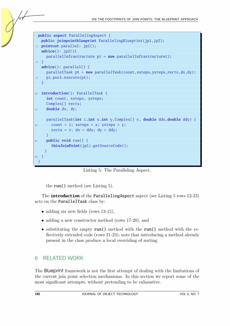
The parallelization is based on the presence of two new classes: ParallelTaskand ParallelInfrastructure that we add to the system. These classes createthe necessary parallel infrastructure; the former represents a skeleton for the threadexecution with an empty run() method, that will be filled with the code extrudedby the aspect (listing 5, rows 21-23), the latter deals with a ThreadPool of fourthreads, as required. These two classes are not relevant to the discussion and forsake of brevity they are not reported, the details can be found in [20] chapter 6.
We use the blueprint and the aspect showed in Figure 4 to identify the portionof the method and to execute it as an asynchronous method. To do this, we mustlocate two join points:
• a local join point (called jp2) before the first statement will be added thecreation of a new instance of the parallelInfrastructure class, and
• a region join point (called jp1) that enclose the code portion that will bereplaced by the code to start a thread with the extruded code as the body of
VOL 6, NO. 7 JOURNAL OF OBJECT TECHNOLOGY 185
ON THE FOOTPRINTS OF JOIN POINTS: THE BLUEPRINT APPROACH
public aspect ParallelingAspect {public joinpointblueprint ParallelingBlueprint(jp1,jp2);
3 pointcut parallel: jp1();advice(): jp2(){
parallelInfrastructure pi = new parallelInfrastructure();6 }
advice(): parallel() {parallelTask pt = new parallelTask(count,xsteps,ysteps,rects,dx,dy);
9 pi.pool.execute(pt);}
12 introduction(): ParallelTask {int count, xsteps, ysteps;Complex[] rects;
15 double dx, dy;
parallelTask(int i,int x,int y,Complex[] r, double ddx,double ddy) {18 count = i; xsteps = x; ysteps = y;
rects = r; dx = ddx; dy = ddy;}
21 public void run() {thisJoinPoint(jp1).getSourceCode();
}24 }}
Listing 5: The Paralleling Aspect.
the run() method (see Listing 5).
The introduction of the ParallelingAspect aspect (see Listing 5 rows 12-23)acts on the ParallelTask class by:
• adding six new fields (rows 13-15),
• adding a new constructor method (rows 17-20), and
• substituting the empty run() method with the run() method with the re-flectively extruded code (rows 21-23); note that introducing a method alreadypresent in the class produce a local overriding of sorting.
6 RELATED WORK
The Blueprint framework is not the first attempt of dealing with the limitations ofthe current join point selection mechanisms. In this section we report some of themost significant attempts, without pretending to be exhaustive.
186 JOURNAL OF OBJECT TECHNOLOGY VOL 6, NO. 7

6 RELATED WORK
In [18], Nagy et al. propose a new approach to AOP by referring to program unitsthrough their design intentions to answer the need of expressing semantic pointcuts.Design intention is represented by annotated design information, which describesfor example the behavior of a program element or its intended meaning. Instead ofreferring directly to the program, their approach provides a new language abstractionto specify pointcuts based on some design information. Design information areinserted inside the base program using annotations and they are associated manually,derived on the presence of other design information and, through superimposition.The key benefit of this approach is that it reduces direct dependencies betweenthe crosscutting concerns and the program source. Unfortunately, this approachbreaks the obliviousness [6] property. This property is broken because certain designinformation has to be specified by the software engineer, and moreover the softwareengineer must use a consistent and coherent set of design information for each sub-domain of an application.
In [5], Douence and Südholt propose an AO approach, called EAOP, based on theobservation of dynamic events. In EAOP, aspects are expressed by events emittedduring execution of the base program and are defined by two languages: a crosscutlanguage, that allows the definition of execution points where an aspect may mod-ify the base program, and the action language, which enables the execution of thebase program to be modified. The implemented tool supports four kinds of events:method and constructor calls and their return events. This approach needs a pre-phase to instrument the source code of the base program to generate events. Wethink that new kinds of event would be necessary, since these kinds are not muchexpressive. Moreover, the pointcut definition is strictly coupled with the base code,since it contains method and constructor names. Finally, the base program mustbe modified to insert the necessary events. In [4], the authors extended their workto take into consideration the whole history of the program executions. These kindof aspects are more expressive than those based on atomic points because relationsbetween execution events can be expressed. Join points may denote not only syn-tactic information (e.g., instructions) but also semantic information (e.g., dynamicvalues). Nevertheless, the crosscut definition is also strictly coupled to the basecode, since it contains, like in their previous work, program element names, such asmethod names.
Tourwé et al. [25] have proposed an advanced pointcut managing environment,based on machine learning techniques. They try to deal with the well-know problemsof the AOP languages by including the notion of inductively generated pointcutsin the language itself. In this way developers can specify pointcuts by using agraphical interface, that offers a view on the source code, and an inductive logicprogramming algorithm that is responsible for computing the pointcut definition.This approach is more expressive and permits to overcome the previous problems,but it still does not permit to identify a pointcut inside the method bodies. On thecontrary, since the inductive logic programming algorithm computes the pointcutdefinition automatically, the developer no longer has precise control over this.
VOL 6, NO. 7 JOURNAL OF OBJECT TECHNOLOGY 187

ON THE FOOTPRINTS OF JOIN POINTS: THE BLUEPRINT APPROACH
Gybels et al. [7] have dealt with the so called arranged pattern problem. Cross-cutting languages use pattern matching to capture join points. This is a goodtechnique to describe the intended semantics of a crosscut but it is still dependentof the naming convention. Gybles et al. have proposed a more flexible linguisticmechanism to implement crosscutting as patterns and consequently avoiding theexposed pattern matching problem. Essentially, their crosscut language is a logicprogramming language, based on Prolog. Their join point model is based on theAspectJ one, since the join points are related to key events in the execution of anobject-oriented program. They use SmallTalk as a base language, and use the follow-ing join points: message receptions by an object, message sends by an object, theaccessing and updating of an object’s state and the execution of code blocks.
In [24], Stein et al. presented a new graphical approach to model pointcuts.Their approach deals with modeling and graphical visualization of places and con-ditions of crosscutting. At the implementation level, join points represent “hookswhere enhancements may be added”, on modeling level, join points are rendered bymodel elements. In particular, their approach uses UML classifiers to represent joinpoints in structural models, and UML messages to represent join points in behavioralmodels. For the designation of join points they introduce a new graphical mech-anism called Join Point Designation Diagram (JPDD). A JPDD contains, whenfully specified, a description of structural and behavioral constraints. The struc-tural part is described with a notation that combines the syntax of class diagramsand object diagrams, and the behavioral part is described by a notation based onsequence diagrams. The approach is loosely coupled with the base program, andfollows a graphical approach like us, but by using JPDD it is not possible to identifyjoin points inside method body, between two instructions, since they use sequencediagrams it is only possible to identifies join points on method calls.
In [14], Klein et al. presented a new semantics-based aspect weaving algorithm forhierarchical message sequence charts (HMSCs). They chose HMCS as the scenariomodel. Scenario languages are mainly used to describe behaviors of distributedsystems at an abstract level or to capture requirements in early development stages.In this work, they used message sequence charts (MSC), that are very similar to UML2.0 sequence diagrams, so the approach used in this paper could also be applied tosequence diagrams as well. Behaviors and aspects are defined by using MSC. Anaspect defines a part of behavior that should be replaced by another one every timeit appears in the semantics of the base specification. This approach suffers fromseveral limitations: the matching process can only be performed if each join pointappears inside a bounded fragment of a behavior, another limitation is that the MSCshould not exhibit two non-disjoint cycles where the pointcut matches. Finally, sinceit is based on sequence diagram it only possible to describe message between objects.
In [17], Mohd Ali and Rashid present a general state-based join point model.The aim of their work is to expose high-level join points in the code, based on thestates and state transitions of the system, by providing a state-based AOP languageplatform that allows such join points to be exposed. This approach turns to safety-
188 JOURNAL OF OBJECT TECHNOLOGY VOL 6, NO. 7

7 CONCLUSIONS
critical systems, where to capture system states is an important part of the system.Since a state-based pointcut construct permits to specify criteria for join pointsthat refer to the program’s current state (i.e., run-time values). In their notion,a crosscutting system state is defined as an abstract state machine, and they usethe transitions of this abstract state machine that are controlled by state guards,to identify the join points during the execution. This approach utilizes a join pointmodel conceptually different from AspectJ. It is very useful for safety-critical or real-time systems, but for other kinds of applications, it is not so intuitive to use. Inaddition, this approach is quite coupled to the base application, since it is necessaryto know the state models of system behavior.
7 CONCLUSIONS
Current aspect-oriented approaches suffer from well-known problems that rely on thesyntactic coupling established between the application and the aspects. A commonattempt to give a solution consists of freeing the pointcut definition language fromthese limitations by describing the join points in a more semantic way.
This paper presents the Blueprint framework, a novel approach to join pointidentification less coupled to the base-code and providing a finer granularity ofselection based on context description. Pointcuts are specified by using patterns(blueprints) of the application expected behavior. More precisely, a join pointblueprint is a template on the application expected behavior identifying the joinpoints in their context. In particular join points are captured when the patternmatches portion of the application behavior.
Compared to the current approaches, we can observe some advantages. Firstof all, we have a more behavioral pointcut definition. In the join point blueprintdefinition we identify the context of the computational flow we want to match, andthe precise point we want to capture. Notwithstanding that, we can still select thejoin points by using syntactic and structural specification, which is only necessarywith a more detailed blueprint. Last but not least, our approach is quite general. Itcan be applied to every programming language (at the cost of adapting the weavingalgorithm to the characteristics of the new language) and used to mimic all the otherapproaches to AOP. There is also a drawback; the matching phase is quite complexand demands time and space. Fortunately, most of the weaving phase is done onceduring the compilation and does not affect the performance of the running program.
The Blueprint framework has been completely specified in [20] and a prototypehas been implemented. In the future, our plans include improving the prototype, torealize a specific tool to draw the blueprints (at the moment we use Poseidon4UML7),to organize the statement in class of equivalences for the actions (e.g., i++ and i=i+1will be recognized by the same class) and to extend the reflective API. Finally, wewant to better check the scalability and robustness of the framework in the software
7http://www.gentleware.com
VOL 6, NO. 7 JOURNAL OF OBJECT TECHNOLOGY 189
ON THE FOOTPRINTS OF JOIN POINTS: THE BLUEPRINT APPROACH
evolution context.
ACKNOWLEDGMENTS
The authors wish to thank Jeff Gray for his help in revising the English of thispaper and the anonymous reviewers for their help in improving the paper contentwith their suggestions.
References
[1] Walter Cazzola, Jean-Marc Jézéquel, and Awais Rashid. Semantic Join PointModels: Motivations, Notions and Requirements. In Proceedings of SPLAT’06,Bonn, Germany, March 2006.
[2] Walter Cazzola and Sonia Pini. Join Point Patterns: a High-Level Join PointSelection Mechanism. In MoDELS’06 Satellite Events Proceedings, LNCS 4364,pages 17–26, Genova, Italy, October 2006. Springer.
[3] Walter Cazzola, Sonia Pini, and Massimo Ancona. Design-Based PointcutsRobustness Against Software Evolution. In Proceedings of the 3rd ECOOPWorkshop on Reflection, AOP and Meta-Data for Software Evolution (RAM-SE’06), pages 35–45, Nantes, France, July 2006.
[4] Rémi Douence, Pascal Fradet, and Mario Südholt. Trace-Based AOP. InRobert E. Filman, Tzilla Elrad, Siobhán Clarke, and Mehmet Akşit, editors,Aspect Oriented Software Development, chapter 9, pages 141–150. Addison-Wesley, October 2004.
[5] Rémi Douence and Mario Südholt. A Model and a Tool for Event-Based Aspect-Oriented Programming (EAOP). Technical Report TR 02/11/INFO, École desMines de Nantes, November 2002.
[6] Robert E. Filman and Daniel P. Friedman. Aspect-Oriented Programming isQuantification and Obliviousness. In Proceedings of OOPSLA 2000 Workshopon Advanced Separation of Concerns, Minneapolis, USA, October 2000.
[7] Kris Gybels and Johan Brichau. Arranging Language Features for MoreRobust Pattern-Based Crosscuts. In Proceedings of the 2nd Int’l Conf. onAspect-Oriented Software Development (AOSD’03), pages 60–69, Boston, Mas-sachusetts, April 2003.
[8] Christoph M. Hoffmann and Michael J. O’Donnell. Pattern Matching in Trees.Journal of ACM, 29(1):68–95, 1982.
[9] Wes Isberg. AOP@Work: Check out Library Aspects with AspectJ 5. January2006.
190 JOURNAL OF OBJECT TECHNOLOGY VOL 6, NO. 7

7 CONCLUSIONS
[10] Kazunori Kawauchi and Hidehiko Masuhara. Dataflow Pointcut for IntegrityConcerns. In Proceedings of the AOSD’04 Workshop on AOSD Technology forApplication-level Security, Lancaster, UK, March 2004.
[11] Andy Kellens, Kris Gybels, Johan Brichau, and Kim Mens. A Model-drivenPointcut Language for More Robust Pointcuts. In Proceedings of SPLAT’06,Bonn, Germany, March 2006.
[12] Gregor Kiczales, Erik Hilsdale, Jim Hugunin, Mik Kersten, Jeff Palm, and BillGriswold. An Overview of AspectJ. In Proceedings of ECOOP’01, pages 327–353, Budapest, Hungary, June 2001. ACM Press.
[13] Gregor Kiczales, John Lamping, Anurag Mendhekar, Chris Maeda, CristinaVideira Lopes, Jean-Marc Loingtier, and John Irwin. Aspect-Oriented Pro-gramming. In Proceedings of ECOOP’97, LNCS 1241, pages 220–242, Helsinki,Finland, June 1997. Springer-Verlag.
[14] Jacques Klein, Loïc Hélouët, and Jean-Marc Jézéquel. Semantic-based Weavingof Scenarios. In Proceedings of AOSD’06, pages 27–38, Bonn, Germany, March2006. ACM Press.
[15] Christian Koppen and Maximilian Störzer. PCDiff: Attacking the Fragile Point-cut Problem. In Proceedings of the European Interactive Workshop on Aspectsin Software (EIWAS’04), Berlin, Germany, September 2004.
[16] Hsiao-Tsu Lu and Wuu Yang. A Simple Tree Pattern-Matching Algorithm.In Proceedings of the Workshop on Algorithms and Theory of Computation,Chiayi, Taiwan, December 2000.
[17] Noorazean Mohd Ali and Awais Rashid. A State-based Join Point Model forAOP. In Proceedings of the 1st ECOOP Workshop on Views, Aspects andRole (VAR’05), in 19th European Conference on Object-Oriented Program-ming (ECOOP’05), Glasgow, Scotland, July 2005.
[18] István Nagy, Lodewijk Bergmans, Wilke Havinga, and Mehmet Akşit. Utiliz-ing Design Information in Aspect-Oriented Programming. In Proceedings of 4thAnnual International Conference on Object-Oriented and Internet-based Tech-nologies, Concepts, and Applications for a Networked World (Net.ObjectDays),LNI 61, pages 39–60, Erfurt, Germany, September 2005.
[19] Harold Ossher and Peri Tarr. Hyper/J: Multi-Dimensional Separation of Con-cerns for Java. In Proceedings of ICSE’01, pages 729–730, Toronto, Ontario,Canada, 2001. IEEE Computer Society.
[20] Sonia Pini. Blueprint: A High-Level Pattern Based AOP Language. PhD the-sis, Department of Informatics and Computer Science, Università di Genova,Genoa, Italy, June 2007.
VOL 6, NO. 7 JOURNAL OF OBJECT TECHNOLOGY 191

ON THE FOOTPRINTS OF JOIN POINTS: THE BLUEPRINT APPROACH
[21] Awais Rashid and Ana Maria Moreira. Domain Models Are NOT Aspect Free.In Proceedings of MoDELS’06, LNCS 4199, pages 155–169, Genoa, Italy, Octo-ber 2006. Springer.
[22] J. Alan Robinson. A Machine-Oriented Logic Based on the Resolution Principle.Journal of the ACM, 12(1):23–41, January 1965.
[23] Kouhei Sakurai and Hidehiko Masuhara. Test-based Pointcuts: A Robust Point-cut Mechanism Based on Unit Test Cases for Software Evolution. In Proceedingsof Linking Aspect Technology and Evolution revisited (LATE’07), Vancouver,British Columbia, Canada, March 2007.
[24] Dominik Stein, Stefan Hanenberg, and Rainer Unland. Modeling Pointcuts.In Proceedings of the AOSD Workshop on Aspect-Oriented Requirements Engi-neering and Architecture Design, Lancaster, UK, March 2004.
[25] Tom Tourwé, Andy Kellens, Wim Vanderperren, and Frederik Vannieuwen-huyse. Inductively Generated Pointcuts to Support Refactoring to Aspects. InProceedings of SPLAT’04, Lancaster, UK, March 2004.
[26] Naoyasu Ubayashi, Genki Moriyama, Hidehiko Masuhara, and Tetsuo Tamai.A Parameterized Interpreter for Modeling Different AOP Mechanisms. In Pro-ceedings of ASE’05, pages 194–203, Long Beach, CA, USA, 2005. ACM Press.
[27] Alexandre Vasseur. Dynamic AOP and Runtime Weaving for Java- How DoesAspectWerkz Address It? In Robert E. Filman, Michael Haupt, KatharinaMehner, and Mira Mezini, editors, Proceedings of the 2004 Dynamic AspectWorkshop (DAW’04), pages 135–145, Lancaster, England, March 2004.
ABOUT THE AUTHORS
Walter Cazzola (Ph.D.) is currently an assistant professor at theDepartment of Informatics and Communication (DICo) of the Uni-versità degli Studi di Milano, Italy. His research interests include re-flection, aspect-oriented programming, programming methodologiesand languages. He has written and has served as reviewer of severaltechnical papers about reflection and aspect-oriented programming.
Sonia Pini is a PhD student and research assistant at the Depart-ment of Informatics and Computer Science (DISI) of Università degliStudi di Genova, Italy.
192 JOURNAL OF OBJECT TECHNOLOGY VOL 6, NO. 7