on the flow of a compressible fluid through...
TRANSCRIPT

767
On the Flow of a Compressible Fluid through Orifices By D. A. Jobson*
By making certain basic assumptions, the author has determined a theoretical expression for the contraction coefficient, C, appropriate to an orifice when transmitting a compressible fluid, either above or below the critical pressure ratio, provided that the corresponding value for incompressible flow, Ci, be known.
INTRODUCTION When a fluid is discharged through a convergent nozzle, con- ditions across the exit section are generally assumed, with little error, to be sensibly uniform. The exit velocity may therefore be predicted from one-dimensional considerations, thus enabling the mass flow to be determined. This approach is not appropriate to the exit conditions across an orifice, since the streamlines are generally still contracting, so that the flow pattern is essentially two- or three-dimensional in character in this region. If, however, conditions may be assumed to be nearly uniform across some other section, such as at a wena conhacta or at a throat, the principles of energy, momentum, and continuity may enable both the size of the jet and the conditions across it to be simply determined at this section.
Such principles, when applied to the discharge of an in- compressible fluid through a Borda mouth-piece, for example, show that, if friction and gravity may be neglected, the jet has a contraction coefficient of 0-5. By the application of similar reasoning it will be shown that a theoretical expression for the contraction coefficient, C, may be determined, appropriate to an orifice when transmitting a compressible fluid, either above or below the critical pressure ratio, provided that the corresponding value for incompressible flow, Ci, be known.
Comparison with such experiments as those of Stanton (1926)t, Schiller (1933) and Perry (1949) indicates that the mass flow through a sharp-edged orifice may be predicted to within a few per cent at any pressure ratio. These tests were carried out on one type of orifice, transmitting either air or superheated steam, but the theory is more general in character, and further com- parisons with tests are needed.
The present analysis considers cases in which the effect of friction is small, gravity and heat transfer may be neglected, and isentropic changes of state may be represented over the range considered by a law of the type :
plpn = constant The above assumptions, which are adopted in most nozzle and
orifice problems, are generally found in practice to give adequate accuracy, without making the analysis excessively tedious. The theory is divided into two parts; in the first, the pressure ratio across the orifice is assumed to be greater than the critical value, so that the flow is everywhere subsonic; in the second, choked flows are considered. The former case assumes constant con- ditions across the vena contracta which the jet may be expected ultimately to form, and the latter case makes a similar assumption concerning the first throat, where sonic conditions are postulated.
The contraction coefficient is defined as the ratio of the above minimum areas to the nominal projected area of the orifice (normal to the jet) and, since at the critical pressure ratio the vena contracta may be identified with the first throat, the two definitions are compatible for the borderline case dividing the two rkgimes. It is perhaps worth noting at this stage that although for supercritical conditions the flow is choked, in so far as conditions are sonic at the first throat, the mass flow does not become independent of the downstream pressure. This charac- teristic difference between the behaviour of the flow through a
The MS. of t h i s paper was received at the Institution on 6th August 1954.
* Emi?&eerhfz Laboratory Royal Naval College, Greenwich. t An alphabetical fist ofr&rences is given in ~pp,=.~& 11.
nozzle (which always flows full) as distinct from an orifice (through which contraction of the jet occurs), was noted and qualitatively explained by Stanton (1926), who indicated that the throat of the jet may be expected to increase in size as the back pressure is reduced,
By postulating, in addition, that compressibility effects may be neglected in the approach area to the orifice, quantitative expressions for these phenomena are deduced. Probably the most questionable of the above assumptions is that concerning conditions across the throat for supercritical flows, since the outermost layer must be at the back pressure. However, the curvature of the streamlines, which will be most marked towards the edge of the jet, implies a transverse pressure gradient in this region. This will give rise to a pressure distribution across the throat that is somewhat as indicated in Fig. 1.
AIPROBABLE
ASSUMED
LOCUS PROBABLE PRESSURE DISTRIBUTION
DISTRIBUTION ASSUMED
PROBABLE VELOCITY PROFILE
\
PROFILE ASSUMED
VELOCITY ACROSS AA PRESSURE ACROSS AA Ai
Fig. 1. Throat Conditions for Supercritical Flows
It is beyond the scope of a one-dimensional treatment to incorporate such refinements and, in the subsequent analysis, the throat will be assumed to be at the critical pressure. The error introduced by establishing the equation of motion on this basis will be largely offset by the corresponding assumption that the velocity is sonic across the whole section, whereas in practice it must be supersonic towards the edge of the jet, if the effect of viscosity is negligible. Since the latter factor must tend to retard the outer layers of the jet, some uncertainty, in any event, exists concerning conditions in this region.
Notation. A Projected area of orifice. a Contracted area of jet. C Contraction coefficient of orifice. Ci C, Viscosity correction factor, m&. F f Force defect coefficient. g Gravitational acceleration. H K KN I;! ma Actual mass flow. n
Contraction coefficient of orifice for incompressible flow.
Force defect on reservoir walls.
Total hydraulic head in reservoir. Theoretical mass-flow coefficient of orifice. Theoretical mass-flow coefficient of nozzle. Theoretical mass flow (= Wlg).
Index of isentropic expansion (= y for a perfect gas).
at PENNSYLVANIA STATE UNIV on April 8, 2016pme.sagepub.comDownloaded from
768 ON THE FLOW OF A COMPRESSIBLE FLUID THROUGH ORIFICES
Po P r rc
w W N WO Y P Po
U UC
Pressure in reservoir. Back pressure. Pressure ratio, p/po. Critical pressure ratio. Velocity through contracted area. Critical velocity. Discharge, weiglitltime. Discharge through corresponding nozzle. Specific weight in reservoir. Ratio of specific heats, cp/&. Density at contracted area. Density in reservoir (= wo/g).
SUBCRITICAL FLOW A N D THE FORCE DEFECT COEFFICIENT
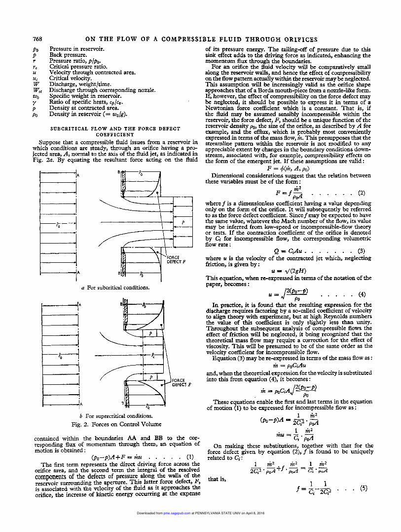
Suppose that a compressible fluid issues from a reservoir in which conditions are steady, through an orifice having a pro- jected area, A, normal to the axis of the fluid jet, as indicated in Fig. 2a. By equating the resultant force acting on the fluid
a For subcritical conditions.
ti FORCE DEFECT F
b For supercritical conditions. Fig. 2. Forces on Control Volume
contained within the boundaries AA and BB to the cor- responding flux of momentum through them, an equation of motion is obtained :
(p,-p)A+F=vi?u . . . . . (1) The first term represents the direct driving force across the
orifice area, and the second term the integral of the resolved components of the defects of pressure along the walls of the reservoir surrounding the aperture. This latter force defect, F, is associated with the velocity of the fluid as it approaches the orifice, the increase of kinetic energy occurring at the expense
of its pressure energy. The tailing-off of pressure due to this sink effect adds to the driving force as indicated, enhancing the momentum flux through the boundaries. For an orifice the fluid velocity will be comparatively small
along the reservoir walls, and hence the effect of compressibility on the flow pattern actually within the reservoir may be neglected. This assumption will be increasingly valid as the orifice shape approaches that of a Borda mouth-piece from a nozzle-like form. If, however, the effect of compressibility on the force defect may be neglected, it should be possible to express it in terms of a Newtonian force coefficient which is a constant. That is, if the fluid may be assumed sensibly incompressible within the reservoir, the force defect, F, should be a unique function of the reservoir density po, the size of the orifice, as described by A for example, and the efflux, which is probably most conveniently expressed in terms of the mass flow, h. This presupposes that the streamline pattern within the reservoir is not modified to any appreciable extent by changes in the boundary conditions down- stream, associated with, for example, compressibility effects on the form of the emergent jet. If these assumptions are valid :
F = #@, A, Po> Dimensional considerations suggest that the relation between
these variables must be of the form : F = f p 2 m 2 . . . . . . (2)
where f is a dimensionless coefficient having a value depending only on the form of the orifice. It will subsequently be referred to as the force defect coefficient. Since f may be expected to have the same value, whatever the Mach number of the flow, its value may be inferred from low-speed or incompressible-flow theory or tests. If the contraction coe5cient of the orifice is denoted by Ci for incompressible flow, the corresponding volumetric flow rate :
where u is the velocity of the contracted jet which, negledng friction, is given by:
This equation, when re-expressed in terms of the notation of the paper, becomes :
Q = CiAu . . . . . . . (3)
= d(2gH)
In practice, it is found that the resulting expression for the discharge requires factoring by a so-called coefficient of velocity to align theory with experiment, but at high Reynolds numbers the value of this coefficient is only slightly less than unity. Throughout the subsequent analysis of compressible flows the effect of friction will be neglected, it being recognized that the theoretical mass flow may require a correction for the effect of viscosity. This will be presumed to be of the same order as the velocity coefficient for incompressible flow.
Equation (3) may be re-expressed in terms of the mass flow as :
and, when the theoretical expression for the velocity is substituted into this from equation (4), it becomes :
liz = PoCiAu
These equations enable the first and last terms in the equation of motion (1) to be expressed for incompressible flow as :
1 tit2 mu = iz, . pJ
On making these substitutions, together with that for the force defect given by equation (2), f is found to be uniquely related to Ci:
1 ri22 h2 1 m 2 2 z 2 $S+f .a = ci - * - POA
that is,
at PENNSYLVANIA STATE UNIV on April 8, 2016pme.sagepub.comDownloaded from
ON THE FLOW OF A COMPRESSIBLE FLUID THROUGH ORIFICES 769
Since the incompressible-flow contraction coefficient lies between the values for a Borda mouth-piece, for which Cj = 0.5, and for a nozzle, for which Ci = 1 , it follows that the force defect coefficient will lie between the limits O< f <05 That f is zero for a Borda mouth-piece might have been anticipated from physical considerations, since in this case the velocity along the walls of the reservoir tends to zero everywhere (except along the re-entrant portion, which gives rise to no additional force along the axis of the jet). The above expression for f provides the key to the remainder of the analysis since it has been argued that it may, with little error, be carried forward unchanged to an analysis of compressible flow through the orifice.
In order to use the equation of motion to determine the dis- charge for compressible flows in terms off, which will now be presumed known, an expression is required for the velocity developed by the contracted jet. For the ideal case of a reversible adiabatic expansion, the Saint-Venant and Wanzel equation is appropriate, and this is, for subcritical flows :
where r denotes the pressure ratio, p/fl0, and n is the index which best represents isentropic expansions by a law of the type :
pip" = constant For a near-perfect gas n may, of course, be identified with y,
the ratio of the specific heats. If the contraction coefficient be denoted by C, the mass flow is then :
m = pCAu
By substituting the value C = 1 the corresponding widely used expression for a nozzle is obtained. This suggests that the corresponding mass-flow coefficient for a nozzle, KN, may be used as a convenient substitution :
Hence, for a nozzle :
and, for an orifice, = K,A1/(PoPo)
liz = CKNA~/(POPO) - . . . . (9) The velocity through the contracted area of the jet is, in either
case, given by equation (6) which on substituting for KN reduces to :
Hence, for subcritical compressible flows, the last term in the equation of motion ( 1 ) for an orifice becomes :
The force defect may similarly be expressed in terms of KN as : F = f . mZ/p&
= f C2(Kd2AP0 so that the equation of motion gives, with those substitutions, a quadratic expression for C :
that is, Therefore
Since it will be noted that KN depends only on r and n, the contraction coefficient is thus determined for subcritical flows as a function of r, n, and f, the latter being found from the incompressible-flow contraction coefficient, Ci.
The theoretical mass flow may then be deduced by factoring the Saint-Venant and Wanzel equation for the mass flow by the
contraction coefficient. It remains to develop an expression corresponding with equation (11) , to cover those cases in which the local Mach number reaches unity in the jet. Such flows, which wi!l be referred to as supercritical, are investigated in the next section.
SUPERCRITICAL FLOWS It has been assumed above that the flow was both reversible
and adiabatic during its expansion between the reservoir and the downstream pressures. This implied that friction and heat transfer could be neglected, and experiments with real fluids support this assumption for high-speed compressible flows. If, however, the downstream pressure is less than a certain critical pressure, pc, so that the stream may become supersonic, the assumption of isentropic flow cannot be valid a Pria; even though the flow be both frictionless and thermally insulated. This is due to the fact that shock waves may form as the fluid recompresses after over-expanding downstream of the first throat. Evidence of this alternative expansion and compression is provided by schlieren and shadowgraph photographs of fluid jets, and these wave phenomena might also be foreseen from theoretical considerations (for example, Stanton 1926).
It is therefore preferable to analyse supercritical flows in terms of a reference section across the first throat, rather than one across the section at which the fluid has expanded to the down- stream pressure. This corresponds to the use of the throat as the control section in convergent-divergent nozzle problems, where conditions at exit are examined subsequently. The equations of motion will therefore be established in terms of the boundaries indicated in Fig. 2b. The pressure and velocity across the jet are considered to have values corresponding to sonic conditions. If these critical values are denoted by sufl ix c the equation of motion is :
The left-hand side of this equation consists of the direct driving force across the area of the orifice, together with the force defect, as before. In this case, however, although the force on boundary AA is unchanged, the back pressure across the area of the orifice, A, is now considered to consist of two parts, the critical pressure, pc, being assumed to act across the throat area (a = CA) and the downstream pressure, p, to act over the area remaining.
For supercritical conditions the expressions for the throat velocity and mass flow are obtained by substituting the critical value of the pressure ratio into equations (6) and (7), as for a choked nozzle :
poA -pA(l- C) -pcCA+ F = lizuc
If the substitution KN is introduced as before to denote the mass-flow coefficient of the corresponding nozzle which, being choked, has the value :
the expressions for uc and tk become :
= CKNA~/(POPO) . . (14) These equations are analogous to equations (9) and (10)
although in this case r is replaced by the constant value rc so that KN is now independent of the pressure ratio r. The flux of momentum and the force defect may now be expressed as :
at PENNSYLVANIA STATE UNIV on April 8, 2016pme.sagepub.comDownloaded from

770 ON THE FLOW OF A COMPRESSIBLE F L U I D THROUGH ORIFICES so that the equation of motion for choked flows is :
This again yields a quadratic expression for C:
This expression, which determines the contraction coefficient of a choked orifice, is seen to reduce to equation (11) when the overall pressure ratio, r, is equal to the critical value, rC. The two equations together determine the contraction coefficient throughout the whole range of pressure ratios. The basic assumption is that the effect of compressibility on the force defect along the reservoir walls may be neglected; this may be expected to be valid so long as the orifice does not approach a nozzle form. For a Borda mouth-piece the force defect is zero and in this case the theory is, in this sense, exact. For such a mouth-piece it is convenient to return to the original quadratic expressions for C, since these reduce to linear equations in the limiting case when f is zero. For a Borda mouth-piece the expressions for its contraction coefficient, C,, thus reduce to,:
rl/n(l -r) W N I 2
c, = ___ . . . . . (16)
for subcritical flows, that is, when rc<r<l , and
for choked flows, that is, when O<r<rc. By substituting the choked value of KN from equation (12)
in equation (17), the latter may be expressed more simply, after some algebraic manipulation, as :
'B = rc(l+n)-r This theoretical expression presupposes that the mouth-piece is short enough for the emergent jet to clear the outer lip of the orifice, although,of course, not so short that there is an appreciable approach velocity along the reservoir wall.
1 -r
SUMMARY AND THEORETICAL CURVES The purpose of the paper is to present a method of finding
the discharge through any orifice, when transmitting a com- pressible fluid, either above or below the critical pressure ratio.
It is presumed that the incompressible-flow contraction coefficient, Ci, is known either from theory or experiment; for example, C; = 0.5 for a Borda mouth-piece and Ci = 'rr/(?~+2) = 0.611 for a plane slit. From C; the strength of the sink effect along the reservoir walls may be inferred. Its intensity determines the magnitude of a force defect coefficient, f, such that :
On the assumption that the flow pattern Within the reservoir is very little influenced by the effect of compressibility, f enables theoretical expressions for the contraction coefficient, C, to be deduced for compressible flows, both above and below the critical pressure ratio. This contraction coefficient enables the mass flow to be determined from the expression :
= C~i-iAl/(POPO) For a nozzle C = 1, and hence KN is the widely used mass-
flow coefficient for a nozzle, based on the Saint-Venant and Wanzel equation. This mass-flow coefficient is shown dotted in Fig. 3 for the typical case of n = 1.4. The contraction Coefficient at any particular pressure ratio may be found by first determining f and KN and substituting their values into either equation (1 1) or equation (15) according to whether r is greater or less than the critical value r,. Some representative curves have been
obtained in this way and plotted in Fig. 4. They indicate that, as the back pressure is reduced, the jet expands progressively, thus causing a continuous increase in the flow rate. This process continues into the supercritical flow range (although at a decreasing rate) so that even though the flow is choked, in the sense that conditions at the throat remain constant, the mass flow continues to increase. This fact is emphasized by defining a theoretical mass-flow coefficient for an orifice K such that :
k A d(POP0)
K = C K , = Curves showing the theoretical variation of K with pressure
ratio have been plotted in Fig. 3, which includes the cor- responding curve for a nozzle (KN). Comparison of the orifice
" I
0 0.2 0:4 I *'o
Fig. 3. Theoretical Mass-flow Coefficient Plotted as a Function of Pressure Ratio for n = 1.4
PRESSURE RATIO, r
0 :2 0 :4 I :o PRESSURE RATIO, I
Fig. 4. Theoretical Contraction Coefficient Plotted as a Function of Pressure Ratio for n = 1.4
at PENNSYLVANIA STATE UNIV on April 8, 2016pme.sagepub.comDownloaded from
ON THE FLOW OF A COMPRESSIBLE FLUID THROUGH ORIFICES 771
1.000 0.932 0.867 0805 0.747 0.692 0.639 0.590 0.543 0.528
and nozzle curves indicates the characteristic difference between their behaviour, the choking of the former being completely masked by the variation of C with r. A numerical example is given in Appendix I.
0.61 1 0.623 0.636 0650 0.665 0.681 0.699 0.717 0.738 0.745
COMPARISON W I T H THE HODOGRAPH S O L U T I O N FOR A P L A N E S L I T
Theoretical results for incompressible flow through orifices can, under certain conditions, be extended to compressible flows, using a hodograph method (Howarth 1953). The results shown in Table 1 for the contraction coefficient of a slit in a plane wall
TABLE 1. CONTRACTION COEFPICIENT OF SLIT IN PLANE WALL
0.61 1 0.622 0.635 0.648 0.663 0679 0.696 0.714 0.734 0.741
- -0.001 -0*001 -0.002 -0.002 -0002 -0.003 -0.003 -0.004 -0.004
have been computed, using tables due to Ferguson and Lighthill (1947).
The results in Table 1 are appropriate to y = 1.4 and the method applies to subsonic flows only (r>0528).
The corresponding values obtained by the method outlined in the paper are as given in Table 2, at roughly comparable
TABLE 2. CORRESPONDING VALUES FOR CONTRACTION COEFFICIENT OBTAINED BY METHOD OUTLINED IN THE PAPER
z I C 1 Error
1 .oo 0.932 0.865 0.805 0.745 0.690 0.640 0.590 0.545 0.528
values of r, together with the ‘error’ treating the hodograph solution as ‘exact’.
It can be seen that the present method slightly underestimates the mass flow, the discrepancy increasing progressively from zero to about 0.5 per cent at the critical pressure ratio.
COMPARISON W I T H EXPERIMENT, A N D CONCLUSIONS Probably the most exhaustively tested orifice is that of the
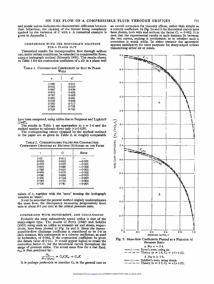
sharp-edged type. The results of Perry (1949) and Schiller (1933) using such an orifice to transmit air and steam, respec- tively, have been plotted in Fig. 5a and b. Since the incom- pressible-flow discharge coefficient is considered to be 0.6 in each instance, this corresponds to a velocity coefficient, as used in hydraulics, of 0.982, if the contraction coefficient be given the datum value of 0.611. It would appear logical to retain the correction factor C, for the theoretical curves throughout the range of pressure ratios. The actual mass flow for a real fluid, ma, is then predicted by :
It is perhaps preferable to consider C, in the general case as
an overall correction for viscosity effects, rather than simply as a velocity coefficient. In Fig. 5a and b the theoretical curves have been drawn, both with and without the factor C, = 0.982. It is seen that the experimental results in each instance lie between the two curves, making it problematic as to whether such a correction is worth while. In either instance the agreement appears satisfactory for most purposes for sharp-edged orifices transmitting either air or steam.
0.6
0.5
0.4
0.3
a
\ - 0.2- \ \ \. n
3 g 0.1- .
2 I \ U
.f v
0 I l=
Z I ! I I
PRESSURE RATIO, r
Fig. 5. Mass-flow Coefficients Plotted as a Function of Pressure Ratio a For n = 1-4. - o - Perry’s tests, using air.
Theory (n = 1.4, Ci = 7~/(7+2)). ---- b For n = 1.3.
- o - Schiller’s tests, using steam. Theory (n = 1.3, Ci = w/(a+2)), ----
at PENNSYLVANIA STATE UNIV on April 8, 2016pme.sagepub.comDownloaded from

772 O N THE FLOW OF A COMPRESSIBLE FLUID THROUGH ORIFICES Further comparisons of the theory with experiment are
required to establish the full range over which the assumptions of the theory are valid. Since the neglect of compressibility within the reservoir cannot be justified when the orifice tends to a nozzle-like form, an upper limit of Cj = 0-7 for application of the theory is tentatively suggested.
ACKNOWLEDGEMENT The author’s thanks are due to the staff of the Aerodynamics
Department of the Royal Aircraft Establishment, Farnborough, for their advice and criticism during the preparation of the paper. It is published by permission of the Admiralty, but the views expressed are personal to the author.
A P P E N D I X I*
NUMERICAL EXAMPLE Many engineers prefer to work in terms of the weight flow, W,
and specific weight, w, rather than the mass flow, ri?, and density, p, to which they are related by:
W - mg w = Pg
From equation (9) the discharge in terms of W becomes : = cKNAgd(popO)
that is, w = CKNA~(gpoW0) . . . . (18)
For a nozzle C = 1, so that the corresponding nozzle discharge is :
WN = KNAz/(g&%) . . . - (19) A number of methods, using charts, tables, or working rules,
have been developed by engineers for calculating W,. As a typical example may be quoted Napier’s equation for a choked nozzle discharging steam :
in which WNis the discharge in Lb. per sec; A is the throat area in in2; and po is the reservoir pressure in Lb/in2.
The discharge through an orifice is related to the cor- responding nozzle discharge by :
C is the contraction coefficient, which may be obtained from Fig. 4 for a specified pressure ratio, r, and incompressible-flow contraction coefficient, C;, as used in hydraulics. Fig. 4 refers strictly to an expansion index n = 1.4, but the value of C does not appear to be critically dependent on n. The corresponding algebraic expressions for C are equations (11) and (15) for sub- critical and choked flows, respectively. In the former expression KN is given by equation (8) and in the latter by equation (12). If the equivalent nozzle discharge has been determined without reference to these equations, KN may alternatively be deduced from WN by use of equation (19).
As a typical numerical example the leakage rate through an annular slit which is 6 inches in diameter and 0.01 inch wide will be estimated. It has an area :
A = n- x 6 in x 0.01 in = 0.1885 in2
and, if it were one stage of a labryrinth seal, for example, it would probably have a hydraulic (that is, incompressible-flow) contraction coefficient, Ci = 0.6. Thus the corresponding force defect coefficient is, by equation (5) :
WN = Apo/7O . . . a . (20)
w = CwN . . . (21)
1 1 f =--- Ci 2 6 3 2
* The nomenclature used in this appendix was adopted at the special request of the author.
Neglecting any velocity of approach or ‘carry over’ effects, the nozzle mass-flow coefficient is, for subcritical flows :
For superheated steam at the critical pressure ratio (r = rc = 0.546, if n = 1.3):
KN = 0.667 For values of r less than 0546, K N remains constant at this
Suppose that the discharge corresponding to a pressure ratio value.
of 0546 is required. From equation (8) (or equation (12)) :
2 X 0.278 X 0 ~ 5 4 6 ~
[ l-d{ ( 2 ~ 0 5 4 6 ~ ) ~ ~ 0 * 4 5 4 ~ 0 - 2 7 8
0.6672 1-
= 2*865[1-0*744] = 0-732
The equivalent nozzle discharge may be obtained from :
or by any other preferred method. If the steam is initially at, for example, 200 Lb/in2 and has 100 O F of superheat, its total heat, or enthalpy, is 1,258 B.t.u./Lb. Its corresponding specific volume is thus, according to Callendar (1939) :
W N = KNA d~gporuo>
1,258-835 ft3/Lb 1 - = 1.253X 2oo WO
that is, Therefore,
wo = 0.377 Lb/ft3
WN = 0.667 x 0.1885 i n 2 d(32.2 ft/sec2 x 200 Lb/in2 x 0.377 Lb/ft3}[l ft/12 in]
Hence, the discharge through the orifice is, finally : = 0.516 Lb/sec
w = C W N = 0.732 x 0516 Lb/sec = 0.378 Lb/sec
This flow rate corresponds with a reservoir pressure of 200 Lb/in2 and a back pressure of 0546 x 200 Lb/in* that is, 109 Lb/in2. Any reduction in the latter does not affect WN but it does increase C, thus increasing the discharge, W, even though the orifice is choked.
A P P E N D I X I1
REFERENCES CALLENDAR, H. L. 1939 ‘Abridged Callendar Steam Tables,
Fahrenheit Units’ (Edward Arnold and Co.). FERGUSON, D. F., and LIGHTHILL, M. J. 1947 Proc. Roy. SOC.,
vol. A192,, p. 135, ‘The Hodograph Transformation in Trans-sonic Flow’.
HOWARTH, E. L. 1953 ‘Modern Developments in Fluid Dynamics: High Speed Flow’, vol. 1, p. 222 (Oxford University Press).
PERRY, J. A., jun. 1949 Trans. A.S.M.E., vol. 71, p. 757, ‘Critical Flow Through Sharp-edged Orifices’.
SCHILLER, W. 1933 Forschung auf dem Gebiete des Ingenieur- wesens, vol. 4, D. 128, ‘Uberkritische Entspannung kompiessibler Flussigkeiten’.
Flow of Gases at High Speeds’. STANTON, T. E. 1926 Proc. Roy. SOC., vol. A l l l , p. 306, ‘The
at PENNSYLVANIA STATE UNIV on April 8, 2016pme.sagepub.comDownloaded from

773
~~
1 *2 1 -3 1 *4 1.667
Communications
0.5645 1-1500 0.5457 1.1462 0.5283 1.1427 0.4871 1.1341
Mr. C. H. BOSANQUET (Billingham) wrote that the author’s method of calculating discharge coefficients depended entirely on the assumption of the constancy off, using his formula
dC c3
df 1-c Values of C approaching unity must therefore be very sensitive to small variations off.
For a perfect nozzle C = 1 by definition but iff = 0.5 and n = 1.4 then C, which was initially unity, fell rapidly with decreasing r and passed through a minimum value of 0.852 when r = 0-7. It then rose to 0.888 at the critical ratio and 0-959 for discharge into a vacuum,
If C was assumed constant then f = 0.5 for small pressure differences and rose to 0.571 at and beyond the critical ratio.
For intermediate conditions it varied nearly linearly with
Critical data for other values of n were given in Table 3.
-=-
pu2.
TABLE 3. CRITICAL DATA FOR VARIOUS VALUES OF n
1 .o 0.6065 I 1.1584 1.1 I 05847 1.1541
A suggested modification of the method was to multiplyfo by a factor which depended on the mean mass flow in the plane of the orifice. The modified value off was given by
Densities and velocities were assumed the same as for a nozzle with the same mass flow. The value of pu in the orifice plane depended on C so that it was necessary to solve by trial. The cal- culation of f was facilitated by employing the useful and adequately accurate approximation
At and beyond the critical ratio the first term was simply equal to c 2 .
Table 1 gave values which fell almost exactly half-way between those calculated by the two methods so that the comparison was inconclusive. For small discharge coefficients and subsonic flows the modification did not make much difference. For values of C approaching unity the modified method gave results which were at least possible; constant f did not. The modified method therefore appeared preferable in spite of its greater complexity.
Mr. R. P. FRA~FX and Dr. P. N. ROWE (London) wrote that as a result of experimental work carried out in the High Speed Fluid Kinetics Laboratory of the Imperial College of Science and Technology (Fraser and Rowe 1954*, Coulter, Fraser, and Rowe (to be published)f., and Coulter 1949$) it was possible to con- tribute some data to compare with the theoretical predictions of the paper in the supersonic range.
* FRASER, R. P., and ROW, P. N. 1954 Jl. of the Imperial College Chem. Eng. SOC., vol. 8, p. 1, ‘A Method of Measuring Very Large G a s Flow Rates’.
t C~ULTER, M. O., PRASBR, R. P., and ROW, P. N. (to be published), ‘A Research into the Design of Supersonic Nozzles for Rockets’.
$ CO~LTER, M. 0. 1949 Ph.D. Thesis, London University, June, ‘On the Efficiency of Supersonic Nozzles’.
Since a velocity coefficient of 1.00 was assumed, the contrad- tion coefficient referred to in the paper was equivalent to a dis- charge coefficient. They had measured the discharge coefficient of various nozzles discharging air at pressure ratios from I equal to 0.012 to 0.033. All the nozzles had a’throat of a nominal diameter of + inch. Comparative discharge coefficients for various nozzles had been obtained by timing the rate of fall of reservoir pressure under similar conditions.
Fig. 6 showed the effect of the entry radius on the discharge coefficient of a supersonic convergent-divergent nozzle. Since the stream was everywhere supersonic downstream of the throat, it could not influence conditions upstream. In other words, in any supersonic nozzle the upstream flow was unaffected by the divergent section and, in particular, the discharge coefficient was unaltered by the supersonic expansion section. That was indeed
A, / A , 6.0 R1 a
b I:O RADIUS OF ENTRY, R/D*
b
Fig. 6. Effect of Entry Radius on Discharge Coefficient of Supersonic Convergent-divergent Nozzle
RID 0 0.5 2.0
CJJ 1 0.939 1 0.960 1 0.986
the case in practice for experiments had shown that the dis- charge coefficient was independent of the divergent section within the limits of experimental error (&0.01). Thus, the nozzle with RIDr = 0 was, in the supersonic (i.e., the author’s supercritical) region, equivalent to an orifike where Cj = 0.6. One with RID, = 2.0 corresponded to a nozzle where Ci = 1.0. The author had predicted a difference in discharge coefficient between those two nozzles of about 0.14 (Fig. 4) whereas they had found 0.047. However, an increased contraction coefficient for incompressible flow (which they had not measured) would bring those results more into line.
at PENNSYLVANIA STATE UNIV on April 8, 2016pme.sagepub.comDownloaded from

774 In addition to measuring the discharge coefficient, they had
measured the thrust reaction generated by the jets from various nozzles. Since the thrust was proportional to the product of dis- charge rate and the acceleration occurring in the nozzle, the thrust coefficient was equal to the product of discharge co- efficient and velocity coefficient. For the case of a convergent-
COMMUNICATIONS ON THE FLOW OF A COMPRESSIBLE FLUID THROUGH ORIFICES modified approach was 0.908 (&0.007). (Unfortunately they had no data for the conventional orifice treated in the paper.) The discharge coefficient for the radiused nozzle was known from the data of Fig. 6 (0.986) and so its velocity coefficient was 0*975/0*986 = 0.989 which justified the author’s assumption, in that instance, that the velocity coefficient was unity. If for the orifice with the modified approach the discharge coefficient for a nozzle of RIDr = 0 was used (0.939), the velocity coefficient for that was 0.908/0.0939 = 0.967 so that in that instance the assumption of a velocity coefficient of unity was much less accurate.
The author appeared to have assumed that there was a vena contracta in compressible flow at small pressure ratios (i.e. high reservoir pressures). Expansion at the exit plane according to the Prandtl-Meyer theory would produce immediate divergence as
I a Radiused nozzle. b Orifice with modified approach.
Fig. 7. Two Nozzles
divergent nozzle cut off at the throat (i.e., without a supersonic expansion section), the velocity coefficient corresponded to that of the author which he had assumed to be unity.
Thrust measurements made on the two nozzles of Fig. 7 showed that the thrust coefficient for that with the radiused approach (RID, = 2.0) was 0.975 and that for the orifice with a
Fig. 8. Pressure Ratio Plotted Against Resultant Angle of Emergence
Experimental points for radiused nozzle. o Experimental points for orifice with modified approach.
Fig. 9. Shadow Photographs r = 0.024.
at PENNSYLVANIA STATE UNIV on April 8, 2016pme.sagepub.comDownloaded from

COMMUNICATIONS ON THE FLOW OF A COMPRESSIBLE FLUID THROUGH ORIFICES 775 shown in Fig. 8, in which the full line showed the theoretical expansion angle that would result from flow through a nozzle subjected to a pressure ratio, r. The treatment was for two- dimensional flow, y = 1-40, and it was assumed that the flow approached the throat perpendicularly. Those angles were achieved in practice for the three-dimensional flow of air through a radiused nozzle at different pressure ratios as was seen from the shadow photograph in Fig. 9a. The emergence angle had been measured from photographs of the jet at different pressure ratios and, for a radiused nozzle, they agreed closely with the theoretical angle as would be seen in Fig. 8.
Unfortunately, in the standard orifice the throat plane was not normally visible, which prevented photographic determination of the emergence angle. For the orifice with a modified approach, it would be seen that the emergence angle had been reduced (Figs. 8 and 9b) because the fluid now had radial velocity directed towards its flow axis which produced a contracting
a For radiused nozzle with r = 0.23.
b For orifice with modified approach and r = 0.23.
c For radiused nozzle with d For orifice with modified r = 0.13. approach and r = 0.13.
Fig. 10. Emereence of a Substantiallv Parallel Tet
effect. That was precisely the effect the author had been con- sidering but the result was a net enlargement, not a contraction.
The emergence angles for their orifice indicated a reduction of the Prandtl-Meyer angle. Thus, a parallel jet would emerge at some pressure ratio and at higher ratios the jet might contract outside the nozzle and the sonic plane would move downstream. Fig. 10 showed that a substantially parallel jet emerged at a pressure ratio of about 0.13 and that above that pressure ratio contraction occurred. It was not possible to measure those emergence angles very accurately but, undoubtedly, the order of the effect was as they had suggested.
They were of the opinion that the author’s theoretical treat- ment must be modified for supersonic flow, particularly at high reservoir pressures, to take into account the expansion effect. They hoped in the near future to publish a comprehensive ac- count of their experimental work in that field (Coulter, Fraser, and Rowe (to be published)).
Mr. D. H. TANTAM (Associate Member) wrote that the mass flow of a compressible fluid through an orifice had been given in equation (7) as
In that an infinitely large reservoir to orifice area ratio was con- sidered.
Many applications were concerned with an orifice in a pipeline when the ratio was much smaller and an equation which took that into account was given by
where Q was the mass flow; Q, the coefficient of discharge; A?, the area of orifice; n, the ratio of area of pipeline to area of orifice; pl, the upstream pressure; p,, the downstream pressure; W1, the specific weight of fluid; y, the ratio of specific heats; and g, the acceleration due to gravity.
Equation (7) was obtained from it of course when n = co. However, in the practical application, the mass flow would
depend on the contraction coefficient C, theoretical values of which had been given in Fig. 4. He would like to know, however, whether any recent information had been established on those coefficients -in addition to the work of Perry (1949) and Schiller (1933) and how those results agreed with theoretical values.
at PENNSYLVANIA STATE UNIV on April 8, 2016pme.sagepub.comDownloaded from

776
Author’s Reply Mr. D. A. JOBSON wrote, in reply to the communications, that he agreed that the force defect coefficient f could not, in general, be considered to be a constant. It was, in some respects, similar to a drag coefficient; just as the latter would depend on the Mach number, so f depended on the mass-flow coefficient and, hence, the pressure ratio r. It was only for orifice-like openings that the influence of compressibility on f might be expected to be small. The Borda mouth-piece represented one extreme for which f was always zero, whatever the value of r. At the other end of the scale, as Mr. Bosanquet had pointed out, f for a nozzle varied almost linearly with r from fo equal to 0.5 to the typical value off equal to 0571 for n equal to 1.4, thereafter it remained constant for choked flows. Hence the ratio f/fo might always be expected to lie between the limits of 1.0 and 1.14 for that value of n, and it could therefore always be estimated with reasonable certainty by some such method as he had suggested. That would enable the theory to be applied beyond the limit Ci equal to 0.7 which he himself had suggested, but he doubted whether the added complication was justifiable below that value.
He noted that Mr. Fraser and Dr. Rowe had measured discharges on an orifice fitted with an exit cone, which discharges were somewhat higher than those obtained and predicted for a simple orifice. It was his own belief that that interesting anomaly might be traced to the fact that the initial contraction of the jet, followed by the subsequent overexpansion downstream, might well, if enclosed in an exit cone, trap a region of dead air. The pressure in that would be Merent from the pressure at exit, and would therefore modify the contraction coefficient and, hence, the mass flow. He had referred to that possibility in the paper under Supercritical Flows, in connexion with the Borda mouth-
piece; in that instance also the emergent jet might not always clear the outer lip downstream.
In regard to the shadowgraphs he was interested to note that they had recorded jet contraction at r equal to 0.23, even with an opening which was heavily countersunk upstream. They had also shown that the emergent angle of a nozzle jet, measured from the axis of the latter, had correlated well with the theoretical Prandtl-Meyer angle. For an orifice, sonic conditions at the lip (i.e. M equal to 1 in Fig. 1) were reached by fluid which was moving radially inwards. Hence, the theoretical curve of Fig. 8 would, in that instance, be shifted back 90 deg., indicating contraction, even at pressure ratios lower than 0.01. The corre- sponding shift for the modified orifice tested by them would be much less, as the countersink implied that the fluid would approach the lip obliquely. That angle would be even less than that of the countersink, owing to local separation at the shoulder, so that the upstream conditions were approaching those for a nozzle.
For the extreme case of an orifice discharging into a vacuum, Prandtl-Meyer theory suggested an inner contracting jet, surrounded by a very small mass of fluid which splayed out- wards as in Fig. 46 of Howarth (1953). The motion of the latter would in practice be considerably modified by growth of boundary layer along the reservoir wall and he was unable to suggest any method of allowing for the expansion effect in that very limited region.
In the matter of recent information on contraction coefficients raised by Mr. Tantam, he hoped shortly to publish a further paper, which would enable velocity of approach effects to be accounted for.
at PENNSYLVANIA STATE UNIV on April 8, 2016pme.sagepub.comDownloaded from