on finite element implementation and computational ...nasa contractor report 185 120 on finite...
TRANSCRIPT

NASA Contractor Report 185 120
On Finite Element Implementation and Computational Techniques for Constitutive Modeling of High Temperature Composites [NASA-CB-185120) O N F I N I T E ELEMENT N89 -2625 1
IPIPLENENTBTXON A N D COBPUT AT I O N B L T E C H N I Q U E S PUB CONSTITUTIVE MODELING OF R I G H TZNPE RATURE COPIPOSITES F i n a l Beport [Akron Uzlclas Univ.) 157 p CSCL 20K G3/39 0220C29
A.F. Saleeb, T.Y.P. Chang, T. Wilt, and I . Iskovitz University of Akron Akron, Ohio
July 1989
Prepared for Lewis Research Center Under Grant NAG3-901
National Aeronautics and Space Administration
https://ntrs.nasa.gov/search.jsp?R=19890016890 2020-05-30T04:21:38+00:00Z

I
TABLE OF CONTENTS
PART I: AN OVERVIEW 1
1. I n t r o d u c t i o n 1
2. Composite C o n s t i t u t i v e Podel ing 3
4. Ful ly- Nonlinear Analysis C a p a b i l i t y f o r S h e l l App l i ca t ions 9
3. Laminated Composite P l a t e / S h e l l Elements 6
5 . Objec t ives and Ou t l ine 10
PART 11: MIXED ELEPENTS FOB LAMINATED PLATES AND SHELLS 13
1. I n t r o d u c t i o n
2. Background and L i t e r a t u r e Review
2.1 Composite F i n i t e Elements
2.1.1 Discrete Layer Model (DLP) Elements
2.1.2 Smeared Laminate Model (SLM) Elements
3. P r e s e n t Element Formulation
3.1 Mixed V a r i a t i o n a l P r i n c i p a l
13
13
13
17
21
28
29
3.2 Element S t i f f n e s s and Mass Matrices 30
3 . 3 Through- the- Thickness I n t e g r a t i o n f o r Composites 33
4. Numerical S t u d i e s 37
4.1 S t a t i c Test Problems: Def l ec t ions and S t r e s s e s 37
4.1.1 A C a n t i l e v e r Beam wi th In-Plane P o i n t Load 37
4.1.2 A S i n g l e Layer Clamped Rectangular Plate Under Uniform Pres su re 38
4.1.3 Two- Layer Clamped and Simply Supported Square P l a t e s Under Uniform Pressu re 39
4.1.4 C y l i n d r i c a l Bending of Symmetric Laminates Under S i n u s o i d a l P res su re 40
TABLE OF CONTENTS (Continued)
4.2 Treatment of Transverse Shear S t r e s s
4.2.1 Approach 1: Modified Shear S t r e s s D i s t r i b u t i o n
4.2.2 Approach 2: Equilibrium-Based Method
4.2.3 Approach 3: Simpl i f i ed S t rength- o f -Mate r i a l s Concept
4.2.4 Addi t iona l Remarks on A l t e r n a t i v e Approaches f o r Transverse Shear S t r e s s Computations
4.3 Test Problems f o r Dynamic Analysis
4.3.1 I s o t r o p i c Material Appl ica t ions
4.3.1.1 I s o t r o p i c Cant i levered Plate
4.3.2 Composite Material Appl ica t ions
4.3.2.1 Aniso t rop ic C a n t i l e v e r Beam
4.3.2.2 Four Layer Symmetric and Anti- Symmetric Square P l a t e s
4.3.2.3 Simply Supported Square Laminated P l a t e s wi th Varying Number of Layers
4.3.3 Addi t iona l Remarks
5. F i n a l Conclusions
PART I11 : COIPUTER IMPLEIENTATION AND NUIERICAL METHODS FOR VISCOPLASTIC ANALYSIS
1. I n t r o d u c t i o n
2. C o n s t i t u t i v e Models
3. F i n i t e Element Equat ions
4. Numerical I n t e g r a t i o n of C o n s t i t u t i v e Bate Equat ions
4.1 E x p l i c i t Schemes
4.2 I m p l i c i t Schemes
41
41
42
43
45
46
49
49
49
50
50
51
52
52
54
54
56
64
67
68
70
.
i i

TABLE OF CONTENTS (Continued)
4.3 Automatic Time Stepping
5 . Computer Implementation
6. Numerical Examples
6.1 A Uniaxial Plane Stress Problem 6.2 A Simple Beam 6.3 A Thick Wall Cylinder
7. Conclusion
PART IV : FULLY- NONLINEAR ANALYSIS CAPABILITY FOR SHELL APPLICATIONS
1. Introduction
2. Geometric and Kinematic Descriptions
2 . 1 Basic Hypotheses
2.2 Coordinate Reference Frames
2.3 Geometry and Kinematics
3 . Variational Principle
4 . Finite Element Formulation
4 . 1 Strain-Field Discretization
4.2 Element Stiffness Equations
4 . 3 Solution Procedure
4.4 Large- Rotat ion Configuration Update
4.5 Strain Update
5 . Stress Update
5 . 1 The Basic Stress- Integration Algorithm
5 .2 Approximat ions
6. Sample Applications
72
73
75
75
77
78
79
80
80
a2
82
83
a4
86
a7
87
88
89
90
91
93
93
95
96
... 111

TABLE OF CONTENTS (Continued)
6.1 Clamped Square Plate Under Uniform Load
6.2 A Pinched Cylinder
6.3 A Pinched Hemisphere
7 . Conclusions
REFERENCES
TABLES
FIGURES
96
96
97
98
100
108
113
iv

PART I: AN OVERVIEW
1. Introduction
At present, metal matrix composites are the primary materials for use in
the propulsion systems of space vehicles due to the light weight/high perfor-
mance requirements . During its service life, the composite will experience,
to a large extent, severe thermal and mechanical loading cycles under high
temperature environments. As a result, such composite components undergo
considerable inelastic deformations, leading to phenomena like ratchet ing , and eventually to their fatigue failure. Obviously, effective utilizations of
high temperature composites require proper design technology, including life
prediction methodologies, for lltypical" composite structural components; such
as turbine blades and combustor liners in the form of composite laminates with
flat (plate- type) or curved (shell- type) geometries.
A valid assessment of the structural integrity, reliability, and life
expectancy of these components requires the development of an improved numeri-
cal capability for their complete, "global- local" (also called progressive-
failure) analysis. This in turn requires consideration of (a) generalized
material behavior, and (b) analytical solution procedure. It is noted here
that f o r such a development, a general framework of wide applicability is
still lacking. The research work reported here is concerned with several con-
tributions to this end.
The term "generalized material behavior" refers to the multiaxial consti-
tutive equations which describe the basic characteristics, and experimentally-
observed phenomena, of the composite material subjected to complex thermo-
mechanical load cycles. These are the most fundamental relations required in
1

any a n a l y s i s ; i n f a c t , t h e i r "accuracy" determines t h e "qua l i ty" of t h e e n t i r e
numerical r e s u l t s . I d e a l l y , t h e s e c o n s t i t u t i v e models should then provide
accu ra t e mathematical r e p r e s e n t a t i o n s of t h e pre- f a i l u r e , f a i l u r e , and post-
f a i l u r e (or damaged) materials response modes.
However, i n view of t h e extremely complex n a t u r e of t h e many phenomena
exh ib i t ed by composite materials a t e l eva ted tempera tures (e.g., s t r o n g
i n i t i a l an i so t ropy ; i n e l a s t i c i t y ; time- and temperature-dependent e f f e c t s l i k e
c reep , r e l a x a t i o n , and recovery mechanisms; f a i l u r e i n t h e form of f i b e r
breakage o r matrix-dominated d u c t i l e r u p t u r e ; c o n s t i t u e n t m a t r i x - f i b e r i n t e r -
a c t ions such as debonding and delaminat ion f a i l u r e , e t c . ) , a concensus favor-
ing a p a r t i c u l a r approach f o r developing a I1comprehensive" c o n s t i t u t i v e model
f o r composite deformation- s t r e n g t h behavior i s no t y e t i n evidence. Neverthe-
l ess , p rogres s i s c u r r e n t l y be ing made on s e v e r a l f r o n t s by va r ious groups a t
NASA Lewis [e.g. 1- 91 . Consider ing t h e "output" composite c o n s t i t u t i v e idea l -
i z a t i o n s r e s u l t i n g from t h i s r e s e a r c h a c t i v i t y , an immediate and important
issue i n t h i s connect ion concerns t h e i r u se i n n o n l i n e a r s t r u c t u r a l a n a l y s i s .
The term " a n a l y t i c a l procedure" used above refers c o l l e c t i v e l y t o a l l
mathemat i ca l /numer i ca l a s p e c t s of c a l c u l a t i o n s needed t o o b t a i n a s o l u t i o n .
To t h i s end, t h e f i n i t e element method i s o f t e n u t i l i z e d as a g e n e r a l frame-
~
work. The p r e s e n t work i s mainly concerned with i s s u e s r e l a t e d t o accuracy,
l t e r i a l l y / geomet r i ca l ly ) non l inea r f i n i t e element s o l u t i o n s f o r laminated
I
r e l i a b i l i t y , and e f f i c i e n c y of a lgo r i thmic s t r a t e g i e s employed i n t h e (ma-
composite p l a t e s and s h e l l s under s ta t ic /dynamic loadings .
l o r e d e t a i l e d d i s c u s s i o n s are g iven below on s p e c i f i c areas and problems
i n v e s t i g a t e d i n t h e subsequent p a r t s of t h e r e p o r t .
2

2 . Composite Constitutive Modeling
Petal matrix composites are typically multi- phase materials, comprised of
"stiff" reinforcing fibers, metal matrix (resin), as well as their inter-
phases. The mathematical characterization of their "macroscopic" thermo-
mechanical def ormat ion/strength properties should theref ore ideally be based
on a consideration of the more basic "microscopic" properties of the indivi-
dual constituents and their interactions; i.e. in the spirit of the so-called
"mesomechanics" approach [SI . In one such micromechanics approach, the overall response of the aggre-
gate composite is "derived" using the rule of mixtures, and often utilizes
some simplifying assumptions regarding the fibers' geometry and packing, for a
representative volume element of the composite [1,8,9]. For example, this has
led to the development of a set of "simplified" nonlinear constitutive rela-
tionships by Chamis and his colleagues at NASA Lewis [e.g. 11.
Other more comprehensive developments of micromechanics-based inelastic
constitutive models for composites at elevated temperatures are currently
underway at NASA Lewis using the method of homogenization. For instance,
based on the periodicity of the composite microstructure, a combined experi-
mental/finite element effort is made by Onat and Leckie [7] t o formulate con-
stitut ive/damage models for the "equivalent" homogenized composite material.
In addit ion, homogenization techniques based on Green functions/Fourier series
are employed by Walker [3] in developing viscoplastic models for general
periodic/nonperiodic heterogeneous composites, which can also account for
surface effects in thin structures.
3

However, in an alternative approach for composite material modeling, the
microscopic effects can be "averaged" at the outset , and the phenomenological (experimentally- observed) aspects of the composite can then be idealized as
for an initially- anisotropic continuum. Various classes of such continuum-
based constitutive representations have been recently developed at NASA Lewis;
i.e., unified viscoplastic models by Robinson and co-workers [e.g. 4, lo].
In view of their generality and ability to account for many important
cyclic load/t ime- dependent phenomena, these multiaxial viscoplast ic equations ;
e.g., as suggested in [4] for transversely- isotropic composites, are presently
among the most well- developed and promising models for practical applications.
They are therefore used here as a base- form for the finite element capabili-
ty developed. Note that further extensions/refinement of this basic formula-
tion are also currently under investigation; e.g. to include high- temperature
I damage (creep damage, low- and high- cycle fatigue damage, etc. [7]). We also
note that the recent research efforts on homogenization in [3,7] will most
likely lead to constitutive macromodels of this same basic structure.
With regard to the above viscoplastic constitutive modeling, a major part
of the present work is concerned with the study of various computational/
implementation aspects associated with their usage in large-scale finite
element analysis [e.g. 5, 11- 171. Pore specifically, the main objectives here
are:
(1) Development of eff icient/accurate integration schemes [e.g. 11- 141
for the resulting system of stiff nonlinear differential equations
using explicit/implicit methods with error control;
4

(2) Design of s p e c i a l procedures f o r t h e s t r u c t u r e d - c o d i n g organ iza t ion
of t h e material model implementation i n t o t h e f i n i t e element s o f t -
ware NFAP [18], such t h a t it becomes no t on ly t r a n s p a r e n t bu t a l s o
immediate t o c o n s t i t u t i v e r e s e a r c h e r s a t NASA Lewis f o r f u t u r e
work.
Development of a " re f ined" uutomut i c l o c a l / g l o b a l time incrementing
a lgo r i thm [e.g. 15- 171 capable of handl ing g e n e r a l loading; e.g.
monotonic o r low-ra te time va ry ing load h i s t o r i e s , as well as t r a n s -
i e n t o r high- cyc le thermomechanical l oad ings , e tc .
(3)
Deta i l ed d e s c r i p t i o n s of t h e above items and r e s u l t s of t h e numerical
t e s t s f o r t h e schemes developed are g iven i n Part I11 of t h i s r e p o r t .
Seve ra l o t h e r a s p e c t s t h a t are no t addressed i n t h i s r e p o r t , but w i l l be
considered i n o u r f u t u r e r e sea rch , are a s s o c i a t e d with t h e i n t r o d u c t i o n of t h e
"damage" response [19] i n t h e v i s c o p l a s t i c model. It i s now well-known t h a t
t h i s p r e s e n t s unique numerical d i f f i c u l t i e s and c a l l s f o r a c a r e f u l i nves t iga -
t i o n of t h e computat ional procedure u t i l i z e d . For example, a t y p i c a l con-
tinuum-damage model i s l i k e l y t o e v e n t u a l l y l e a d t o some s o r t of " s t r a i n -
softening" [20,21]. T h i s may cause t h e f i n i t e element s o l u t i o n t o exhibi t
p a t h o l o g i c a l behavior i n t h e form of o s c i l l a t i o n s and s t r o n g e lement -s ize /
mesh s e n s i t i v i t y , u n l e s s s u i t a b l e " l o c a l i z a t i o n limiters" are in t roduced i n
t h e numerical model [21]. Also, depending on t h e p a r t i c u l a r continuum-damage
theory used , t h e r e s u l t i n g "damagedtt material- moduli matrix may become "un-
symmetric" [20,22] ; i . e . , an e f f i c i e n t symmetrization procedure may t h u s be
needed.
5
Finally, there are cases i n which composite structures may f a i l due t o
excessive o r "moderately- large" viscoplast i c deformations (e. g . s t ra ins of the
order of a few percent, as opposed t o the inf ini tes imal-s t ra in assumption
typically used). One crucial question i n such cases i s how should these
"moderate" ine las t ic s t ra ins be treated i n the f i n i t e element analysis? For
example, the ine las t ic deformations appear as an additive term i n the
consti tutive equations of the unified viscoplastic theory, thus leading t o the
so- called i n i t i a l s t ra in approach which i s typically employed i n f i n i t e
element analysis. This i s equivalent t o an expl ic i t o r constant-stiffness
formulation f o r "small- s t ra ins" viscoplasticity . It i s known that the expli-
c i t method may present numerical ins tab i l i ty o r slow convergence problem,
especially when the composites experience large strains. I n th i s l a t t e r case,
a need therefore ar ises for the development of variable- s t i f fness o r implicit
methods [e.g. 231, which has been t radi t ional ly used f o r time- and rate-
independent p las t ic i ty . This i n t u r n requires careful studies of the possible
ways f o r deriving appropriate material "tangent- s t i f fness" matrices for
viscoplast i c models.
~
I
3 . Laminated ComDosite Plate/Shell Elements
A very important ingredient i n the nonlinear analysis of composite struc-
tural components i s the use of suitable plate/shel l elements representing
structural act i o n of thin/moderately- t h i c k / t h i c k laminated composites. It i s
presently well- established tha t the most effective approaches for geometric
modeling of plates and arbi t rary curved shells are: (a) degenerated shear-
f lexible (middle- surface) elements for t h i n and relatively- t h i c k s i tuat ions;
and (b) two- surface elements (3- D solids) fo r t he thick regime. Despite
6

their popularity, displacement- based models of these types are also known to
exhibit several difficulties [e.g. 24, 25, 271 in applications to isotropic as
well as anisotropic problems (e.g., shear/membrane locking for thin struc-
tures, kinematic deformation modes for reduced integration, etc.).
Alternative formulation approaches have therefore been advocated, e.g.
using various hybrid/mixed methods. In particular, a class of effective and
simple hybrid/mixed plate and shell elements have recently emerged from o u r
previous research work with NASA Lewis [25-301. More specifically, a large
variety of critical test problems, for both linear [25, 271 as well as geo-
metrically- nonlinear [30] situations, have clearly demonstrated the robustness
and accuracy of our simple quadrilateral element (HISH5) for isotropic-
elasticity. A major portion of the present work was thus devoted to mixed
element-technology development applied to composites, for both static and
vibration analyses, as detailed in Part I1 of the report.
In such a development of mixed composite elements for plates and shells,
at least three numerical problems can be anticipated. First, because of their
anisotropy there will be strong interactions among various stress and strain
components in a composite element, which may induce the so-called locking
effect. This needs careful examination. For example, an attempt has been
made by Spilker [32] to formulate a locking-free 8-noded hybrid stress element
for laminated plates. However, in that approach, independent stress functions
were assumed for each individual lamina. This leads to a very large number of
independent stress (strain) parameters per element, thus rendering the analy-
sis prohibitively expensive. Instead, we propose to use a fixed set of stress
( o r strain) functions for a "designated" number of laminae (plies o r layers).
7

This Itdesignatedt1 number has t o be determined on t h e b a s i s of numerical s tudy .
I n f a c t , t h e extreme assumption of u t i l i z i n g layer number independent s t r a i n
i n t e r p o l a t i o n for t h e lamina te e lement , i s u t i l i z e d he re , and was shown t o be
success fu l i n a l l t h e t e s t cases i n v e s t i g a t e d i n Part 11. Thi s i s c e r t a i n l y
of g r e a t advantage from t h e s t andpo in t of computat ional e f f i c i e n c y .
Second, t h e r e i s a need i n us ing an e f f i c i e n t " through-thickness" i n t e -
g r a t i o n scheme t o o b t a i n t h e o v e r a l l c o n s t i t u t i v e p r o p e r t i e s of t h e laminated
composite from t h e corresponding ( v i s c o p l a s t i c r a t e ) equat ions f o r t h e ind i -
v idua l p l i e s ( laminae) . The familiar Gauss quadra ture r u l e f o r i s o t r o p i c
materials i s no t s u i t a b l e f o r laminated composites s i n c e it fa i l s t o cap tu re
the material behavior of each lamina. For numerical expediency, we developed
an " interpret ive" scheme f o r t h i c k n e s s i n t e g r a t i o n t h a t i s combined with
convent iona l Gauss quadra ture f o r in- p lane lamina i n t e g r a t i o n . That i s , a few
sampling p o i n t s i n t h e t h i c k n e s s d i r e c t i o n are p r e s e l e c t e d t o c a l c u l a t e t h e
material matrices f o r an e q u i v a l e n t u n i d i r e c t i o n a l material. Then, t h e cor-
responding q u a n t i t i e s f o r each lamina are i n t e r p o l a t e d accord ing t o i t s
th ickness- l o c a t i o n and f i b e r - o r i e n t a t i o n . It i s be l i eved t h a t t h i s scheme
combines t h e a t t r i b u t e s of computat ional efficiency as well as numerical
accuracy.
F i n a l l y , from t h e viewpoint of gene ra l a p p l i c a b i l i t y t o arbitrary curved
s h e l l s ( i . e . , nonf l a t /nonrec tangu la r e lements ) , t h e need w i l l arise f o r t h e
appropr i a t e d e f i n i t i o n of " f i b e r - o r i e n t a t i o n s " o r "material- symmetry" axes f o r
t h e t l equ iva len t " material a t each in- p lane ( lamina) i n t e g r a t i o n po in t . To
t h i s end, we have implemented a s imple "shape- func t ion" i n t e r p o l a t i o n ( i so -
parametr ic- t y p e ) scheme based on t h e i r va lues a s s o c i a t e d with t h e nodal p o i n t s
8
d e f i n i n g t h e element geometry; i .e . , t h e s o - c a l l e d nodal f i b e r o r material
triads. Note t h a t f o r rec tangular -e lement meshes f o r f l a t p l a t e s , t h i s can be
reduced t o simply s p e c i f y i n g (as i n p u t ) t h e ang le of i n c l i n a t i o n of material-
symmetry axes wi th r e s p e c t t o t h e g l o b a l axes of t h e composite p l a t e .
The va r ious a s p e c t s above have been incorpora ted i n t h e mixed formula t ion
of t h e composite element HPSH5, and i t s a p p l i c a t i o n s t o a number of t es t cases
are desc r ibed i n P a r t I1 of t h e r e p o r t . Emphasis i s p laced on demonstrat ing
i t s response c h a r a c t e r i s t i c s wi th r ega rd t o : 1) mesh- convergence p r o p e r t i e s ;
2) accuracy of stress and displacement p r e d i c t i o n i n s t a t i c a n a l y s i s ; and 3)
f requency and mode p r e d i c t i v e c a p a b i l i t y f o r v i b r a t i o n a n a l y s i s .
4 . Ful ly-Nonl inear Analvsis CaDabil i tv f o r S h e l l A m l i c a t i o n s
I n a d d i t i o n t o material n o n l i n e a r i t i e s , geometr ic n o n l i n e a r i t i e s i n t h e
form of 1) large rotations, and 2) l a r g e o r non-infinitesimal strains, must
be a l s o cons idered i n t h e development of a f u l l y - non l inea r s o l u t i o n procedure
of p l a t e s and s h e l l s [e.g. 30, 311. For example, item (1) i s c r u c i a l i n
s t u d i e s r e l a t e d t o any buckl ing phenomenon (e.g. c reep buck l ing ) . S i g n i f i -
cance of (2) appears i n t h e a n a l y s i s of f a i l u r e o r damage due t o excess ive
deformations. I n t h e s e l a t te r cases, moderate s t r a i n s (on t h e o r d e r of 3-5X)
w i l l be t y p i c a l l y involved. Based on our prev ious exper ience [30], t h e s e
should be p r o p e r l y accounted f o r i n t h e i t e r a t i v e s o l u t i o n scheme t o improve
i t s convergence p r o p e r t i e s .
I n t h i s f i n a l p a r t of t h e i n v e s t i g a t i o n , t h e g e n e r a l framework of f u l l y -
non l inea r curved s h e l l s i s developed f o r t h e mixed elements . Adopting an
updated- Lagrangian approach, a c o n s i s t e n t l y - l i n e a r i z e d form of t h e incrementa l
9

modified Ee l l inge t /Be i s sne r mixed v a r i a t i o n a l p r i n c i p l e i s u t i l i z e d t o d e r i v e
t h e element non l inea r governing equat ions . Emphasis i s p laced on dev i s ing
e f f e c t i v e s o l u t i o n procedures t o d e a l with
(1) element conf igura t ion- update i n t h e presence of large r o t a t i o n s i n
space ;
accurate i n t e g r a t i o n of s p a t i a l stress and s t r a i n f i e l d s . (2)
A r a t h e r comprehensive account of t h e va r ious a s p e c t s of t h i s development
has been r e c e n t l y compiled i n a r e p o r t [30], which was provided t o NASA-Lewis
ear l ie r t h i s y e a r (1989). Therefore , on ly a summary of t h e e s s e n t i a l p o i n t s
and r e s u l t s i n some v a l i d a t i o n tests w i l l be included i n P a r t I V of t h i s
r e p o r t .
5 . Obiec t ives . First-Year AccomDlishments. and Out l ine
I n summary, t h e o v e r a l l o b j e c t i v e s of t h e p re sen t work are given as
fo l lows :
1) To develop robus t and e f f e c t i v e laminated p l a t e / s h e l l e lements based on
t h e mixed method f o r t h e a n a l y s i s f o r s ta t ic and v i b r a t i o n problems.
To develop e f f i c i e n t implementation and time- stepping/numerical- i n t eg ra -
t i o n schemes f o r u n i f i e d v i s c o p l a s t i c c o n s t i t u t i v e models f o r high-
tempera ture composites.
To develop a g e n e r a l framework f o r t h e f u l l y - n o n l i n e a r s t r u c t u r a l analy-
s i s of s h e l l s .
Consider ing t h e above t h r e e items, ou r f i rs t - year accomplishments are
2)
3)
summarized as fo l lows:
With r ega rd t o i tem (1), we have completed t h e formula t ion and t e s t i n g of
an "extended" hybrid-mixed compos i t e element HMSH5 f o r s t a t i c and v i b r a t i o n
10

analyses . Emphasis i s p laced i n t h i s development on: i) robus tness , ii) com-
p u t a t i o n a l e f f i c i e n c y , as well as iii) gene ra l a p p l i c a b i l i t y t o a r b i t r a r y
curved With regard
t o ( i ) a c a r e f u l s e l e c t i o n i s made f o r t h e polynomial f u n c t i o n s i n t h e assumed
s t r a i n f i e l d , t h u s l e a d i n g t o s t i f f n e s s formula t ion t h a t i s k inemat i ca l ly
stab le, free from locking f o r l a r g e " thickness" a s p e c t r a t i o s , r e l a t i v e l y in-
sensitive to geometr ic d i s t o r t i o n s , etc. I n a d d i t i o n , wi th a view toward
( i i ) , i n c o n t r a s t with o t h e r previously-developed hybr id composite p l a t e
elements , we u t i l i z e d a fised set of parameters ; i. e. , a l aye r - number- indepen-
dent assumption, f o r t h e s t r a i n f i e l d d i s c r e t i z a t i o n , t o g e t h e r wi th an effi-
cient "through- th i ckness" i n t e g r a t i o n scheme f o r t h e s t i f f n e s s c a l c u l a t i o n s i n
terms of t h e anisotropic e l a s t i c / v i s c o p l a s t i c p r o p e r t i e s of t h e laminated ele-
ment. A simplified mass matrix was a l s o used, t h u s o b v i a t i n g t h e need f o r
expensive "dynamic condensation" of i t s f i f t h node's degrees- of-freedom.
F i n a l l y , from t h e viewpoint of g e n e r a l a p p l i c a b i l i t y t o arbitrary curved
s h e l l s ( i . e. , nonf l a t / n o n r e c t a n g u l a r elements) i n (iii) , a p p r o p r i a t e def i n i -
t i o n s of " f i b e r - o r i e n t a t i o n s " o r "material- symmetry" axes for t h e "equivalent ' '
material a t each in-p lane (lamina) i n t e g r a t i o n p o i n t were made through t h e
implementat i on of a simple "shape- func t ion" i n t e r p o l a t i o n ( i soparamet r ic - t ype )
scheme based on t h e i r va lues a s s o c i a t e d with t h e nodal p o i n t s d e f i n i n g t h e
element geometry; i . e . , t h e s o - c a l l e d nodal f i b e r o r material triads.
connect ion with r e s e a r c h areas i n item (2) above, t h e major cont r ibu-
t i o n s of t h e f i r s t - y e a r s tudy c o n s i s t o f : i) f o u r d i f f e r e n t v i s c o p l a s t i c
c o n s t i t u t i v e models ( f o r i s o t r o p i c and a n i s o t r o p i c r e sponses ) , and t h e asso-
c i a t e d i n t e g r a t i o n methods, are coded as a separate module i n NFAP so t h a t any
s h e l l s , and several noteworthy aspects are inc luded here .
and
I n
11
f u t u r e ex tens ion or coding modi f ica t ion can be done e a s i l y by a user, i i ) "re-
duced" of v i s c o p l a s t i c models were made r e a d i l y a v a i l a b l e f or appl ica-
t i o n s t o v a r i o u s s t r u c t u r a l components represented by a 2/D continuum, o r
p l a t e / s h e l l e lements , i i i ) f u r t h e r understanding of t h e numerical schemes
employed f o r p r a c t i c a l a n a l y s i s , and i v ) development of a " ref ined" automatic
l o c a l time increment i n g a lgo r i thm capable of handl ing g e n e r a l time- vary ing
load h i s t o r i e s .
f orms
F i n a l l y , i n t h e f i r s t - y e a r i n v e s t i g a t i o n a s s o c i a t e d wi th item ( 3 ) , t h e
general frameluork of f u l l y - n o n l i n e a r a n a l y s i s of curved s h e l l s has been devel-
oped f o r o u r mixed f i n i t e e lements . Adopting an updated- Lagrangian approach,
a c o n s i s t e n t l y - l inear ized form of t h e incremental modified He l l inge r /Be i s sne r
mixed v a r i a t i o n a l p r i n c i p l e i s u t i l i z e d t o d e r i v e t h e element non l inea r
governing equa t ions i n t h e form of tungent (vuriuble) stiffness s o l u t i o n .
Emphasis i s p laced on d e v i s i n g effective s o l u t i o n procedures t o deal with: i)
element configuration- update i n t h e presence of l a r g e r o t a t i o n s i n space; and
i i ) integration of s p a t i a l stress and s t r a i n f i e l d s when l a r g e non-
i n f i n i t e s i m a l s t r a i n s occur . Within t h i s framework, t h e newly-developed non-
l i n e a r element HISH5 was t e s t e d and shown t o e x h i b i t improved convergence
c h a r a c t e r i s t i c s compared t o o t h e r a v a i l a b l e elements.
accurate
Following the overview given i n t h i s f i r s t p a r t , t h e remainder of t h e
r e p o r t i s convenient ly d iv ided i n t o t h r e e s e p a r a t e p a r t s , 11, I11 and IV, des-
c r i b i n g t h e r e s e a r c h work completed i n each of t h e above t h r e e areas (1), (2),
and ( 3 ) , r e s p e c t i v e l y . Each part con ta ins a review of p e r t i n e n t l i t e r a t u r e ,
d e t a i l e d t h e o r e t i c a l and a lgo r i thmic developments, r e s u l t s of numerical tes t
problems f o r v a l i d a t i o n , as well as conclus ions summarizing t h e r e s e a r c h items
planned f o r f u t u r e work.
12

PART 11; MIXED ELEMENTS FOB LAHINATED PLATES AND SHELLS
1. I n t r o d u c t i o n
I n o r d e r t o analyze and des ign some of t h e complex composite s t r u c t u r a l
a p p l i c a t i o n s , f i n i t e element techniques are now almost i n v a r i a b l y used i n
many, i f no t a l l , phases of t h e des ign process . I n a d d i t i o n t o t h e des ign
phases , r e c e n t i n t e r e s t has a l s o begun t o focus on t h e f a i l u r e and va r ious
damage mechanisms a s soc ia t ed wi th composite materials, i .e . matrix cracking ,
delaminat ion/debonding , p ly f a i l u r e , e tc . These types of a p p l i c a t i o n s demand
accura t e stress p r e d i c t i o n s .
Because of t h e above mentioned p o i n t s , cons ide rab le i n t e r e s t and e f f o r t
has focused i n developing a c c u r a t e and e f f i c i e n t composite f i n i t e e lements .
I n t h i s connec t ion , we summarize he re t h e r e s u l t s of ou r r e c e n t r e sea rch
a c t i v i t y on t h e development of an e f f e c t i v e q u a d r i l a t e r a l p l a t e / s h e l l e lement ,
of t h e hybrid/mixed type , f o r t h e s t a t i c and dynamic a n a l y s i s of a n i s o t r o p i c
e l a s t i c i t y .
2. BackPround and Literature Review
2.1 Composite Finite Elements
A l amina te i s t y p i c a l l y cons t ruc t ed of a series of p l i e s s tacked and
bonded t o g e t h e r t o form t h e lamina te . Each of t h e i n d i v i d u a l p l i e s are com-
posed of two d i s t i n c t c o n s t i t u e n t s , f i b e r s and surrounding matrix material,
which possess markedly d i f f e r e n t p r o p e r t i e s . I n p a r t i c u l a r , due t o t h e
d i f f e r e n c e i n shea r ing s t i f f n e s s of t h e matrix and f i b e r s , h igh r a t i o s of
e l a s t i c moduli t o shea r moduli are developed. Thus, t h e c r o s s - s e c t i o n a l
warping, i . e . shea r deformation, of t h e lamina te i s dependent on t h e p l y
o r i e n t a t i o n s i n a d d i t i o n t o t h e p l a t e / s h e l l t h i ckness . Because of t h i s , it i s
13

known t h a t s h e a r deformation has a more pronounced e f f e c t i n laminated
s t r u c t u r e s than i n t h e case of i s o t r o p i c s t r u c t u r e s .
I n c l a s s i c a l laminat i on t h e o r y (CLT) t h e usua l Love- Kirchof f assumptions
of plane s e c t i o n s remaining p l ane are i n e f fec t , t he reby n e g l e c t i n g shea r
deformations t o t a l l y . Obviously, t h i s t ype of t heo ry i s of no va lue except i n
very t h i n p l a t e o r s h e l l a p p l i c a t i o n s . A theory used i n t h i c k p l a t e s i s t h a t
a t t r i b u t e d t o R e i s s n e r - I i n d l i n t y p e of assumptions. I n t h i s ca se , a cons t an t
shear ang le through- the- th ickness of t h e p l a t e i s assumed and has been refer-
red t o as t h e cons t an t shea r ang le theory (CST). Typ ica l ly , some form of
shear c o r r e c t i o n f a c t o r , K , i s chosen t o account f o r t h e through- the- th ickness
shear deformation. These t y p e s of Reissner-Yindl in e lements are t h o s e t y p i -
c a l l y used f o r composite a n a l y s i s .
It has been suggested t h a t whi le t h i s t ype of assumption i s s a t i s f a c t o r y
f o r i s o t r o p i c p l a t e s , it may no t be s u f f i c i e n t f o r laminated p l a t e s and s h e l l s
because of t h e vary ing shea r moduli through- the- t h i c k n e s s of t h e lamina te .
Thus, a l aye rwise cons t an t s h e a r ang le theory (LCST) has been used i n which,
as t h e name i m p l i e s , a cons t an t shea r deformation ang le i s used f o r each p ly .
Using t h e terminology of Bert [33], t h e ma jo r i ty of composite f i n i t e ele-
ments can be ca t egor i zed i n t o two d i s t i n c t groups, namely, (1) a "smeared
laminate model" (SLI) , and (2) a " d i s c r e t e l a y e r model" (DLH). I n t h e SLI
e lements , t h e lamina te i s no t considered as a series of i n d i v i d u a l l a y e r s bu t
a heterogeneous, a n i s o t r o p i c medium. con-
s t a n t s h e a r ang le theo ry (CST) t y p e of elements are i n effect smeared models
s i n c e they do no t d i s t i n g u i s h t h e s h e a r s t r a i n ang le s on an i n d i v i d u a l l a y e r
b a s i s . I n t h e D L I e lements , each l a y e r r e t a i n s i t s own i d e n t i t y and i n some
cases i s t r e a t e d as a "sub-element" of t h e t o t a l element. I n terms of shea r
I n terms of shea r deformation, t h e
14

deformation, t h e layerwise cons t an t shea r ang le theo ry , (LCST) are d i s c r e t e
models s i n c e each l a y e r i s permi t ted t o have i t s own s h e a r angle .
I n a d d i t i o n , t h e above c l a s s i f i c a t i o n s may be f u r t h e r subdivided. i n t o
groups which u t i l i z e lower- o r d e r and higher- o r d e r approaches. The c r i te r ia
f o r d i s t i n g u i s h i n g between a lower- o r d e r versus a higher- o r d e r approach de-
pends on t h e o r d e r of t h i ckness -coord ina te (z) terms inc luded i n t h e expansion
of va r ious displacement components. That i s , expansions inc lud ing only up t o
l i n e a r terms i n z are descr ibed as lower-order approaches, whereas, t h o s e in-
c luding h i g h e r - t h a n - l i n e a r powers of z are c o l l e c t i v e l y r e f e r r e d t o as higher-
o rde r approaches. It should be noted t h a t a p p l i c a t i o n of e i t h e r approach can
be made on t h e entire laminate, as i n t h e SLM elements , o r t o individual
layers, as i n t h e DLM element.
A t t h i s p o i n t , it may be u s e f u l t o b r i e f l y d i s c u s s t h e h ighe r -o rde r theo-
r ies i n gene ra l . There have been numerous h igher o r d e r t h e o r i e s developed,
Beddy [34], Lo [35] and Murakami [36], t o account f o r s h e a r deformation. I n
t h e s e approaches, h ighe r -o rde r expres s ions con ta in ing q u a d r a t i c and cub ic
terms are used f o r t h e displacement o r stress f i e l d equat ions . By us ing such
expressions, accurate p r e d i c t i o n s of in-plane displacements, shear s t ra in and
stress d i s t r i b u t i o n s th rough- the - th i ckness are obta ined . The g o a l and motiva-
t i o n f o r u s ing t h e s e h ighe r -o rde r t h e o r i e s i s t o be a b l e t o o b t a i n an a c c u r a t e
p r e d i c t i o n of t h e lamina te behavior wh i l e s t i l l us ing a 2-dimensional ap-
proach, as compared t o 3- dimensional o r e l a s t i c i t y approaches. Thus, t h e
higher- o r d e r t h e o r i e s attempt t o s t r i k e a balance between complexity and
accuracy.
I n t h e above, two approaches have been used t o deve lop t h e h ighe r -o rde r
t h e o r i e s , namely, a displacement- f i e l d assumption o r a stress- f i e l d assump-
15

t i o n . The most commonly used i s t h e d i sp lacemen t - f i e ld assumption, where i n
t h i s ca se , t h e new lamina te t h e o r y i s based upon a k inemat i ca l ly admiss ib le
displacement f i e l d .
The main t h r u s t of t h e "h igher -order theory" models i s t o p r imar i ly d e a l
w i t h t h e complex c r o s s - s e c t i o n a l warping of t h e lamina te . A l l of t h e l i t e r a -
t u r e reviewed , i. e. Reddy . Lo, Purakami, emphasizes how well t h e i r p a r t i c u l a r
approach can p r e d i c t t h e "zig- zag" shape of t h e in- p lane displacement d i s t r i -
bu t ions . I n r e a l i t y , t h e c r u c i a l t es t appears t o be how well t h e theo ry pre-
d i c t s t h e through- the- t h i c k n e s s d i s t r i b u t i o n of shea r stresses. I n f a c t ,
accu ra t e methods t o p r e d i c t such t r a n s v e r s e s h e a r stress v a r i a t i o n s i s cur-
r e n t l y one of t h e very a c t i v e r e sea rch areas i n composite modeling; see
a d d i t i o n a l r e l a t e d d i s c u s s i o n s i n Sec. 4.2. ~ For example, Reddy [34] g i v e s r e s u l t s showing through- the- t h i c k n e s s shea r
s t ress d i s t r i b u t i o n s obta ined d i r e c t l y from c o n s t i t u t i v e equa t ions and e q u i l i -
brium equa t ions . The d i s t r i b u t i o n s obta ined from t h e c o n s t i t u t i v e equat ions
are qui te poor wi th stress d i s c o n t i n u i t i e s occur r ing a t t h e l a y e r i n t e r f a c e s .
The only improvement over t h e lower-order t heo ry , i .e . CLT, i s t h e pa rabo l i c
shea r stress d i s t r i b u t i o n wi th in each l a y e r and t h e a b i l i t y t o s a t i s f y t h e
stress f r e e c o n d i t i o n s a t t h e t o p and bottom s u r f a c e s of t h e lamina te . On t h e
o t h e r hand, i f p l y equ i l ib r ium equat ions are used t o c a l c u l a t e t h e shear
s t r e s s e s , more a c c u r a t e and c o r r e c t shea r stress d i s t r i b u t i o n s are obtained.
As be shown la ter i n Sec. 4, t h e p re sen t element can a l s o o b t a i n such a
p red ic t ion through t h e use of a modified shea r s t r a i n d i s t r i b u t i o n method,
which i s s imple r t han us ing h ighe r -o rde r theory . I n t h e r e s u l t s of Iurakami
[36], t h e s h e a r stresses are obta ined from equ i l ib r ium equa t ions , and as ex-
w i l l
16

pected show good agreement with t h e exac t s o l u t i o n , whi le Lo [35] makes no
mention of t h e s h e a r stress d i s t r i b u t i o n r e s u l t s , only f l e x u r a l stresses.
2.1.1 D i s c r e t e Layer Yodel (DLP) Elements
A group of 8-node i sopa rame t r i c h y b r i d - s t r e s s e lements f o r t h i n t o t h i c k
laminated p l a t e s have been developed by S p i l k e r [37,38,39]. Together wi th a
higher- o r d e r approach t h e hybrid- stress formula t ion is u t i l i z e d . The l a t t e r
i s claimed t o be p r e f e r r e d s i n c e it i s easier t o s a t i s f y i n t e r l a y e r stress
c o n t i n u i t y and lamina te s u r f a c e cond i t ions exac t ly . The main feature of t h i s
element i s t h a t displacements and non-normal c r o s s - s e c t i o n r o t a t i o n s are inde-
pendent from l a y e r t o l a y e r [37]. Thus, each l a y e r posses ses i t s own degrees
of freedom (d.0.f .) and remains a d i s c r e t e l a y e r . I n a d d i t i o n , i n d i v i d u a l
s t r e s s expres s ions are w r i t t e n f o r each l a y e r . S t r e s s c o n t i n u i t y through- the-
t h i ckness i s t h e n e s t a b l i s h e d by r e l a t i n g c e r t a i n terms of t h e ad jacen t ith
and i+lth l a y e r s . Also, c e r t a i n displacements of t h e a d j a c e n t l a y e r s are
r e l a t e d t o e s t a b l i s h displacement c o n t i n u i t y through- the- t h i ckness . The DLP
approach i s used i n o r d e r t o account f o r t h e seve re c r o s s - s e c t i o n a l warping on
t h e laminate. a
higher- o r d e r displacement assumption i s used. S p e c i f i c a l l y , t h e in- p l ane
d isp lacement , v , i s on t h e o rde r of 23 and t h e t r a n s v e r s e d isp lacement , w , i s
of 22 o r d e r , where z i s t h e t h i c k n e s s coord ina te . This i s i n c o n t r a s t t o t h e
usual a p p l i c a t i o n s of t h e h ighe r -o rde r t heo ry , which i s u s u a l l y app l i ed on t h e
lamina te l e v e l .
This point i s emphasized by t h e fact t h a t w i t h i n each l a y e r ,
Because each l a y e r i s considered t o be d i s c r e t e , forming t h e element
s t i f f n e s s becomes an involved process . B a s i c a l l y , an assembly process i s
17

required t o form the element, o r laminate, s t i f fness from the individual layer
st iffnesses. Reference [38] likens the process t o the conventional element
"assembly" operations i n f i n i t e element codes. That i s , s t ress parameter
"pointers" and nodal displacement "pointers" are required t o add individual
layer s t i f fness contributions t o the overall element s t i f fness . Thus, the
element requires a large amount of computation ju s t t o form the element s t i f f -
ness. As a matter of f ac t , Spilker does p o i n t ou t that the number of d.0.f.
and laminate s t r e s s parameters grow rapidly as the number of layers increase,
and computer core storage may l i m i t the number of layers allowed [37].
I n reference [38], i n an attempt t o eliminate some of the layer depen-
dency of the element, "kinematic constraints" are introduced. These con-
s t r a in t s are such tha t a number of the i n d i v i d u a l layer displacements are
related t o a laminate set of d.0.f. located a t the mid-plane of t h e laminate.
The element d.0.f . are on ly those associated wi th the mid-plane reference
surf ace making the element's d. o . f . layer independent. Thus, the element now
has a t o t a l of 40 d.0.f . independent of the number of layers. Also, the
higher- order displacement assumptions of [37] are simplified t o again decrease
the complexity of the element. Thus, i n effect , the detailed in-plane dis-
placement response i s neglected, yet the element s t i l l re ta ins the higher-
order s t ress expressions. By using such a compromise, the element s t i l l gives
accurate transverse displacement as compared t o CLT and good through- the-
thickness s t ress dis t r ibut ions as compared t o e las t ic i ty .
Finally, i n reference [39] Spilker introduces an element which i s to ta l ly
layer independent. For moderately thick laminates, 0.01 < h/L < 0.1, shear
deformation a f fec ts s t ructural behavior but the individual layer warping ef-
18

f ects are n o t significant . Thus, i n d i v i d u a l layer non- normal cross- sect i o n
rotations and individual s t ress parameters may no t be necessary. I n t h i s
element, the t o t a l number of d.0.f. and s t ress parameters are independent of
the number of layers. F i r s t , the nodal d.0.f. are related t o the in-plane and
transverse displacements a t the mid- plane reference surface of the laminate,
and t o the non-normal cross-section rotations of the laminate. Second, the
s t ress f i e l d s i n each layer are expressed i n terms of laminate s t ress para-
meters. A l l the through-the-thickness integrations can therefore be isolated
and they are then analytically evaluated. Specifically, t h i s refers t o the
calculation of the laminate material properties, i .e . ax ia l , bending, and
coupl ing s t i f fnesses . I n e f fec t , laminate theory i s used t o calculate these
quantit ies, thus effectively eliminating any numerical integration through-
the-thickness. Since these are the o n l y layer dependent quantit ies for the
element, the computation time w i l l increase slowly as the number of layers
increase.
The element predicts transverse displacements quite well, as compared t o
exact solutions, f o r laminate thickness ra t ios of 0.01 < h/L < 0.25, where h
i s the t o t a l thickness of the laminated plate , and L i s a characterist ic
II spanwise" length. The s t r e s s dis t r ibut ions show good agreement w i t h exact
solutions f o r thickness ra t ios of 0.01 < h/L < 0.108, i .e. up t o moderately
t h i c k laminates. The s t ress dis t r ibut ions for t h i c k laminates, h/l=0.25, are
n o t i n good agreement. Th i s i s attr ibuted t o some of the above mentioned
simplifications introduced i n t o t h i s element t o improve i t s efficiency.
Details of improved CPU times can be found i n [39], and i n general t h i s ele-
ment proves t o be more e f f ic ien t than the previous elements.
19

Thus, the t r end i s t o move away from the true discrete layer model, which
i s ineff ic ient from a computational standpoint, t o a semi-discrete layer
model. While the DLI elements give very detailed displacement and s t ress in-
formation, one needs t o question whether or n o t such de ta i l i s necessary.
Spilker s ta tes that such de ta i l may o n l y be required f o r special cases such as
non- l inear post-f i r s t - p l y f a i lu re , laminate strength measurements, e tc . [37].
B u t f o r typical structural applications such de ta i l i s no t necessary.
Chaudhuri and Seide [40] present a triangular 6- node displacement based
element. It i s somewhat similar t o Spilker's original element [37], i n that
the t o t a l d.0.f . of the element i s layer dependent. The t o t a l laminate ele-
ment consists of N "layer elements" f o r a N-layer laminate. Each layer ele-
ment i s tr iangular i n shape and consists of 6-nodes wi th 5 d.0.f. per node.
This element i s different from Seide's previous work i n that the element can
assume a general triangular shape. The reason given fo r choosing a tr iangular
over a quadrilateral shape i s tha t it allows easier modeling of holes and
cut- o u t s . I n terms of the d.o.f., each "layer element" has two independent in-plane
displacements and two independent rotations. Because each layer has indepen-
dent rotations, i . e . shear angles, Seide uses the term layerwise constant
shear angle, LCST, t o describe t h i s type of element. The remaining d.o.f . ,
transverse displacement, i s no t independent from layer t o layer. That i s ,
each element shares the same transverse displacement w i t h the adjacent nodes
that have the same in- plane coordinates through- the- thickness. T h i s s a t i s f i e s
the assumed condition of transverse inextensibil i ty, i . e . laminate thickness
does n o t change, and interlayer continuity.
I
20

However, Seide's element differs from that of Spilker's layer- dependent
element in one important aspect. That is, because of its underlying displace-
ment- based formulation, the former element must satisfy the displacement
continuity requirement , thus allowing the typical numerical integration scheme to be used through-the-thickness to form the element stiffness from the indi-
vidual layer stiffnesses. In contrast, since Spilker used assumed- stress
fields, which are not continuous through-the-thickness, the complex "pointer"
method was required. Seide uses Heaviside functions to write a continuous
function through- the- thickness of the laminate for the in- plane displacements,
with the resulting expressions being similar to those used in the higher-order
theory approaches. The expression for transverse displacement is constant , as discussed.
The results produced by this element shows good agreement with the
elasticity solutions. In particular, the transverse displacement predictions
for a thick laminate, i.e. L/h = 4, the CLT error is around -787, while the
LCST and CST give -3X and -5 .2%, respectively. Thus, for thick laminates,
Seide believes that LCST is required for acceptable results. But it should be
noted t h a t for moderately th ick laminates, L/h = 10 t o 20, both t h e error be-
tween the LCST and CST theories becomes almost negligible. Thus, since CST
theory gives adequate results for thin to moderately thick laminates, is LCST
necessary?
2 . 1 . 2 Smeared Laminate Iodel (SLI) Elements Another classification of composite finite elements are what may be
Post of the original compos- termed as smeared laminate model (SIL) elements.
21

i t e element developments f a l l under t h i s p a r t i c u l a r ca tegory . The elements of
Panda and Natara jan [41], Chang and Sawamiphakdi [42], Beddy [43], Rogers and
Knight [44], and Haas and Lee [45], reviewed i n t h i s paper , use a "smeared"
laminate i n t h e sense t h a t t h e element does not r e t a i n t h e d i s c r e t e p l y s t r u c -
t u r e , I n s t e a d , by e i t h e r numer-
i c a l i n t e g r a t i o n through- the- t h i c k n e s s o r t h e a p p l i c a t i o n of lamina te theo ry
an equ iva len t lamina te o r element s t i f f n e s s i s formed. I n most ca ses , t h e use
of t h i s smearing technique i s s u f f i c i e n t f o r p r e d i c t i n g t h e g l o b a l s t r u c t u r a l
response.
as do t h e DLM elements d i scussed previous ly .
The elements of Panda [41] and Chang [42], can be considered as represen-
t a t i ve examples of early composite f i n i t e elements based upon a "degenerated"
s o l i d s h e l l ' t h e o r y . I n p a r t i c u l a r , t h e element of Panda i s a s i m p l i f i c a t i o n
of an element o r i g i n a l l y developed by Iawemya and Davies [46]. This o r i g i n a l
element cons idered independent r o t a t i o n s f o r each l a y e r , t h u s t h e t o t a l
degrees of freedom of t h e element was dependent on t h e number of l a y e r s .
Panda states t h a t t he use of independent l a y e r r o t a t i o n s does not n e c e s s a r i l y
g ive improved r e s u l t s , bu t does i n c r e a s e t h e s ize of the problem cons iderably
[41]. Thus, t h e element of Panda uses a cons tan t normal r o t a t i o n through-the-
t h i ckness of t h e lamina te . Also, d e t a i l s are provided on t h e method of i n t e -
g r a t i n g through- the- t h i ckness us ing a " th ickness concept" t o e f f e c t i v e l y
account This change of v a r i a b l e
scheme i s common t o most elements which i n t e g r a t e th rough- the- th ickness t o
form t h e element s t i f f n e s s . The r e s u l t s provided by Panda show good agreement
with e l a s t i c i t y s o l u t i o n s . For L/h > 20 e r r o r s i n d e f l e c t i o n s and stress are
on the o rde r of -7% and f o r L/h > 10, t h e d e f l e c t i o n s are wi th in -15% and
f o r t h e d i f f e r e n t l a y e r material p r o p e r t i e s .
22

stresses are wi th in -10%. Panda shows t h a t t h i s p a r t i c u l a r method of i n t e -
g r a t i n g through- the- t h i c k n e s s provides good accuracy f o r t h i n p l a t e s and rea-
sonable accuracy f o r t h i c k p l a t e s [41].
A limitat ion of t h e prev ious displacement based "degenerated" elements i s
i n d e a l i n g with t h e problem of locking . That i s , most s h e l l e lements have a
tendency t o ove rp red ic t t h e element s t i f f n e s s as t h e t h i c k n e s s becomes small,
which l e a d s t o locking. I n r e fe rence [45], Haas and Lee p r e s e n t a nine-node
assumed s t r a i n degenera te s o l i d s h e l l element , which was chosen because it has
been shown t h a t t h e problem of locking i s e l imina ted . Th i s i s achieved by
seg rega t ing t h e energy express ion i n t o components of i n -p l ane , bending, and
transverse shea r s t r a i n energy terms. are
included coupl ing e f f e c t s are p resen t i n non- symmetric composite lami-
na te s ( f o r symmetric lamina tes o r i s o t r o p i c materials, t h i s term w i l l v an i sh ) .
By seg rega t ing t h e in -p lane and t r a n s v e r s e shear s t r a i n terms, t h e source of
locking i s e l imina ted . The s t r a i n polynomial assumptions were chosen t o pro-
duce a s t a b l e element with no spur ious kinematic modes [45]. An important
po in t i s t h a t t h e s e s t r a i n polynomials are used t o d e s c r i b e t h e behavior of
the entire laminate through- the- th ickness , u n l i k e t h e stress polynomials of
S p i l k e r Because of t h i s , t h e element deg ree ' s of freedom are not l a y e r
dependent.
Also, coupl ing s t r a i n energy terms
s i n c e
[37].
R e s u l t s are presented f o r symmetric laminated p l a t e s sub jec t ed t o a
s i n u s o i d a l load . For square laminated plates wi th l e n g t h - t o - t h i c k n e s s r a t i o s
of 10 < L/h < 400, t h e element shows good agreement wi th e l a s t i c i t y and t h i c k
plate t h e o r y [45]. One i n t e r e s t i n g p o i n t i s t h a t no mention i s made of any
shea r c o r r e c t ion f a c t o r s f o r shea r deformation, y e t r easonab le r e s u l t s are
obtained.
23

I I Recall t h a t p rev ious ly t h e h igher -order theory was shown as app l i ed on an
i n d i v i d u a l b a s i s , i n p a r t i c u l a r , t h e DLH elements of S p i l k e r . On t h e o t h e r
hand, Beddy [43] uses t h e h ighe r -o rde r approach on a lamina te o r element
l e v e l . e lement , as desc r ibed i n r e fe rence [43], i s c l a s s i f i e d as a SLI
element where t h e h ighe r -o rde r displacement f i e l d s are used t o d e s c r i b e t h e
The
e n t i r e lamina te th rough- the - th i ckness . S p e c i f i c a l l y , Reddy’s element i s based
upon t h e p rev ious ly d iscussed theo ry set f o r t h i n r e f e r e n c e [34]. Again, as
most proponents of t h e higher- o r d e r t heo ry emphasize, t h e c l a s s i c a l p l a t e
theory based upon t h e Kirchhoff-Love assumption i s no t adequate t o d e s c r i b e
t h e behavior of moderately t h i c k lamina tes . By us ing a h ighe r -o rde r t heo ry ,
t h e d i s t r i b u t i o n of t h e t r a n s v e r s e shea r stresses i s accounted f o r
and thereby e l i m i n a t e s the need f o r t h e shea r c o r r e c t i o n f a c t o r s , [43].
p a r a b o l i c
Results are presented covering d e f l e c t i o n s , stresses, buckl ing loads , and
v i b r a t i o n f r equenc ie s . I f a t t e n t i o n i s focused p r i m a r i l y on d e f l e c t ion and
s t ress r e s u l t s , t h e h igher -order element does show e x c e l l e n t agreement with
exac t e l a s t i c i t y s o l u t i o n s f o r t h e cases presented he re . Reddy aga in empha-
s i z e s t h e d i sc repancy between t h e CLT and HSDT, wi th t h e d i f f e r e n c e becoming
more s i g n i f i c a n t as t h e r a t i o of l o n g i t u d i n a l t o t r a n s v e r s e moduli i nc reases .
But as i s common with t h e h ighe r -o rde r approach, Beddy does p o i n t o u t t h e
a s soc ia t ed drawbacks. First, higher- o r d e r stress and moment r e s u l t a n t s arise
from t h e fo rmula t ion which are d i f f i c u l t t o understand p h y s i c a l l y . This same
problem i s ev iden t i n t h e elements of S p i l k e r . And secondly, t h e theo ry con-
t a i n s d e r i v a t i v e s of t h e t r a n s v e r s e d e f l e c t i o n s . Thus, t h e element r e q u i r e s
func t ions with C1 c o n t i n u i t y [43].
24
I n reference [47] , Lakshminarayana and l u r t h y present a shear f lexible
f i n i t e element which i s based upon a generalized theory of Yang, Norris, and
Stavsky, YNS. It i s "shear flexible" i n the sense that shear deformation i s
accounted for . Using t h i s theory, the coupled bending and stretching response
of the laminated plate i s expressed i n terms of f ive unknowns. That i s , three
displacements; u,v,w, and two rotations; e,,ey, of the normal [47]. The
element i t s e l f i s triangular i n form and has three nodes located a t the ver-
t ices . Complete cubic polynomials are used t o approximate the displacements
and rotations w i t h i n the element and were chosen because the authors believe
that higher- order elements have advantages over lower- order elements when
dealing w i t h laminated composite plates and shel ls [47]. There are 15
degrees-of-freedom per node; three displacements, two rotations, and the i r
derivatives. The authors believe that by using the derivatives of displace-
ments and rotations a t the nodes i s an advantage because it allows evaluation
of the s t resses directly a t the nodes instead of a t Gauss points which i s
common i n most other elements. Bu t t h i s also makes the element very computa-
t ionally expensive since f o r three nodes w i t h 15 degrees- of- freedom per node
g ives Thus, one mus t ques-
t i o n whether the l u x u r y of having the stresses direct ly a t the nodes i s real ly
advantageous. Again, as wi th previous SIL elements, the element s t i f fness i s
par t ia l ly based upon laminate theory t o reduce the m u l t i - layer composite i n t o
a smeared single layer plate.
a t o t a l of 45 degrees-of-freedom f o r t h e element .
Lakshminarayana and Pur thy present a large number of cases wi th a variety
of geometry, loading, support conditions, and plate thicknesses t o access the
performance of the element and the importance of shear deformation effects.
I n each case, the performance i s measured by comparing t o e i ther analytical o r
25

o t h e r f i n i t e element s o l u t i o n s obta ined from a r e fe rence by Noor and l a t h e r s .
The element appears t o ag ree very well with t h e o t h e r s o l u t i o n s , both f i n i t e
element and e x a c t , i n a l l cases presented . Because of t h e l a r g e amount of
d e t a i l e d r e s u l t s and t h e v a r i e d cases, t h i s r e fe rence w i l l s e rve well as a
I source of benchmark problems f o r t h e present composite f i n i t e element
i development.
Rogers and Knight [44] presen t a h igher -order element with a s p e c i f i c
a p p l i c a t i o n t o f i l amen t - wound composite p re s su re v e s s e l s . It is poin ted ou t
i n the pape r , t h a t t h e main mot iva t ion f o r t h e development of t h e element i s
t o provide an e f f i c i e n t and s imple means of modeling t h e complex composite
s t r u c t u r e found i n t h e p re s su re v e s s e l s . Also, because of t h e low s h e a r
s t i f f n e s s of t h e material, s i g n i f i c a n t shear e f f e c t s between t h e l a y e r s
develop, t h u s r e q u i r i n g a h ighe r -o rde r displacement f i e l d . The proposed ele-
ment i s similar t o t h e h ighe r -o rde r e lements prev ious ly d i s c u s s e d , but a d i s -
i t i n g u i s h i n g f e a t u r e presented i s t h a t t h e o rde r of t h e through- the- th ickness
polynomial i s user s e l e c t a b l e . The element subrout ine i n t e r n a l l y gene ra t e s
t h e a p p r o p r i a t e shape f u n c t i o n s us ing Lagrange i n t e r p o l a t i o n polynomials.
This i s u n l i k e most elements i n which t h e shape f u n c t i o n s are permanently
coded i n t o t h e element sub rou t ines . This e l i m i n a t e s t h e need t o manually
de r ive t h e shape f u n c t i o n s and t h e i r d e r i v a t i v e s . Whether o r no t t h i s f e a t u r e
i s really an advantage i s not c l e a r . By us ing such a h ighe r -o rde r element,
t h e t y p i c a l m u l t i - l a y e r composite can now be e f f e c t i v e l y modeled us ing one
element t h rough- the - th i ckness . As proof of t h e need of a h ighe r -o rde r ele-
ment, d a t a i s presented which shows t h e amount of computation time saved by
using one higher- o r d e r element through- the- t h i ckness , as compared t o t h e use
of i nd iv idua l e lements f o r each p ly .
26

The element s t i f f n e s s i s genera ted by performing numerical i n t e g r a t i o n
through- the- t h i c k n e s s on a l aye r - by- l a y e r b a s i s . Unlike most composite ele-
ments reviewed t h a t use t h i s technique , t h i s element u ses a ze ro th -o rde r r u l e
( r ec t angu la r i n t e g r a t i o n r u l e ) with t h e weighting f a c t o r s be ing p ropor t iona l
t o t h e l a y e r t h i c k n e s s i n which t h e i n t e g r a t i o n po in t r e s i d e s . This a l lows
the e f f e c t s of each i n d i v i d u a l l a y e r ’ s material p r o p e r t i e s t o be e f f e c t i v e l y
modeled. The a u t h o r s do p o i n t ou t though, t h a t no r e l a t i o n s h i p e x i s t s between
the polynomial o r d e r , n , and t h e number of i n t e g r a t i o n p o i n t s r equ i r ed t o
i n t e g r a t e t h e polynomial e x a c t l y us ing t h i s zeroth- o r d e r i n t e g r a t i o n ( u n l i k e
s tandard Gauss quadra tu re ) . This c r e a t e s a v a r i a b l e i n t h e accuracy of t h e
f i n i t e element s o l u t i o n which can be only e l imina ted by exper ience with t h i s
p a r t i c u l a r element [44].
A l l of t h e papers reviewed t h u s f a r , have been l i m i t e d t o l i n e a r problems
with r ega rd t o d e f l e c t i o n s , v i b r a t i o n s , and buckl ing loads . One of t h e ob-
vious reasons f o r such l i m i t e d work i n non l inea r composite a n a l y s i s i s t h e
added complexi ty of t h e problem. Indeed, cons ider ing composite l i t e r a t u r e i n
g e n e r a l , c losed- form or s o l u t i o n s t h a t do e x i s t are f u r t h e r l i m i t e d t o
a very narrow c l a s s of problems; i . e . , f o r t h e most p a r t , t o symmetrically
l ayered c r o s s - p l y and ang le -p ly lamina tes . This i s due t o the presence of
coupl ing terms, which are peculiar t o composite materials, t h a t often make any
a n a l y t i c a l s o l u t i o n f o r unsymmetric l amina te s i n t r a c t a b l e . Th i s accounts f o r
t h e repea ted use of t h e 0/90 class and o t h e r symmetric l amina te s , which do no t
conta in t h e s e coupl ing terms, as r e f e r e n c e s o l u t i o n s i n most f i n i t e element
l i t e r a t u r e ; e .g . Pagano [48] and Whitney [49].
27

A comprehensive review of research on both linear and nonlinear analysis
of composites was given in [50]. In addition, a penalty-type formulation to
overcome shear locking for thin plates together with the composite theory by
Yang, Norris, and Stavsky (YNS) , and various classical first- approximation shell theories were utilized in [50] to develop a displacement- based element
for nonlinear analysis. Similar applications of these types of elements can
also be found in [52,53].
3 . Present Element Formulation
The element to be presented here is the extension of earlier work by
Saleeb et.al. [27] to the modeling of multi-layered composite materials. It
is the objective of this investigation to see how well the element will per-
form with the minimum amount of modifications to its basic formulation. If
the element yields satisfactory results, as such, a good foundation will have
been established in which to build upon for future work. It is also desirable
to keep the element as "simple" as possible thereby minimizing the computa-
tional expense, i.e. an element which has the total d.0.f. independent of the
number of layers.
This element may be classed as a hybrid/mixed or assumed-strain shell
element. That is, in the underlying variational principle, both the displace-
ment and strain fields are approximated independently. Since the ultimate
goal of the research is the application of the elements for high-temperature
metal- matrix composite structural analysis, i.e. non- linear material analysis,
it appears that utilizing a strain assumption, as opposed to a stress assump-
tion, is most desirable. That is, in the case of material non-linearity it is
28

still entirely valid to assume a linear variation of bending strains through-
the- thickness of the "thin" laminate, while such an assumption for associated
stresses is certainly not valid. Also, choosing a strain field a priori is
much easier to justify than it would be for a particular stress field assump-
t ion.
What is different in the present approach from some of the previously
mentioned elements is that the assumed strain field used represents the ent ire
laminate. Thus this element can be classified as a smeared laminate model,
SIL, type, utilizing a first-order o r constant shear angle (CST) theory. Its
general formulation is derived from a "modified" form of the Hellinger-
Beissner variational principle, as described in the sequel.
3.1 lixed Variational Principal
The "modified" Hellinger-Beissner principle, including the kinetic energy
term for the dynamics problem, is expressed as
- sU TT(u-i)dSu]dr
where
c = independently assumed strains n L c = B q = strains derived from assumed displacements - - D = material stiffness matrix
p = material density -
u = assumed element displacements
29

li = element v e l o c i t i e s
T = boundary t r a c t i o n s -
- f - = boundary f o r c e
V = volume
r = time
A l l q u a n t i t i e s wi th an overbar , (-), are prescr ibed q u a n t i t i e s , and Sg and Su
are por t ions of t h e element boundary over which t r a c t i o n s and displacements
a r e p re sc r ibed . By t a k i n g t h e f i r s t v a r i a t i o n of t h e f u n c t i o n a l with r e s p e c t
t o t h e s t r a i n s e , and d isp lacements u, - and invoking t h e s t a t i o n a r i t y
cond i t ions 6rR = 0 ,
t h e equ i l ib r ium equa t ions , s t r a in -d i sp lacemen t r e l a t i o n s , i .e . , n e = e = B u i n V
T B a + f = p i i i n V - - - -
t oge the r wi th t h e a s s o c i a t e d su r f ace- t r a c t i o n s and displacement boundary
cond i t ions on Su and Su, r e s p e c t i v e l y , are recovered. I n t h e above, B i s a
d i f f e r e n t i a l s t r a i n - displacement o p e r a t o r , and BT i s t h e a s s o c i a t e d "matrix-
divergence" o p e r a t o r .
3 . 2 Element S t i f f n e s s and Mass Matrices
The d e r i v a t i o n of t h e s t i f f n e s s and mass mat r ices w i l l be obta ined from
t h e previous ly desc r ibed f u n c t i o n a l rB, now r e f e r r i n g t o lamina-coordinate
systems. J u s t i f i c a t i o n f o r choosing such a re fe rence frame i s g iven i n d e t a i l
30

i n o u r p rev ious work [27]. Thus, t h e f u n c t i o n a l can be expressed as,
where dV = dxdydz = I J l d r d s d t , i n which r , s , t are t h e n a t u r a l ( i soparamet r ic )
coord ina tes and J i s t h e Jacobian- of- coordinate- t r ans fo rm matrix. For t h e
f i n i t e element d i s c r e t i z a t i o n , t h e displacements , u, are i n t e r p o l a t e d from t h e
nodal degrees- of- freedom,
-
where t h e Nk are t h e two-dimensional shape f u n c t i o n s i n terms of l o c a l
paramet r ic )
d e r i v a t i o n s , t h e above equat ion can be w r i t t e n symbol ica l ly as,
( i so -
For s i m p l i c i t y i n terms of t h e coord ina te s , r and s , f o r node k.
u = wq - - - ( 5 )
where fi are "modified" shape f u n c t i o n s obta ined by combining terms i n Eq. (4) .
I n t h e above, , f (g ) , with i = 1 , 2 , 3 , are t h e components of t h e f i b e r t r i a d
a s s o c i a t e d wi th node ( k ) , which are de f ined as i n [27].
The independent ly- assumed s t r a i n s , E , are approximated i n terms of t h e -,
s t r a i n parameters, 8, as fo l lows - : = (6)
where P - i s t h e s t r a i n i n t e r p o l a t i o n mat r ix . Again f o r b r e v i t y , we refer t o
31

[27]
derived from the assumed displacements are expressed as
fo r details of the form for the interpolation matrix P. The strains, ?, -
L where B is now a l o c a l strain-displacement matrix.
Now, substituting E q s . ( 5 ) , (6) and (7) into E q . ( 3 ) , the functional
be comes
Equation (8) can be simplified and written as
where the matrices E, G, I and Q are defined as, - - - -
32

1 1 Q e - =11 ll NT?lJldrdsdt - - - (13)
I n o rde r t o e l i m i n a t e t h e s t r a i n s on t h e element l e v e l , s t a t i o n a r i t y i s
invoked on Eq, (8) i n terms of - v a r i a b l e s , t hus y i e l d i n g
Now, s u b s t i t u t i n g Eq. (14) back i n t o t h e f u n c t i o n a l rR and t a k i n g t h e
v a r i a t i o n wi th r e s p e c t t o nodal displacement parameters , we f i n a l l y g e t t h e
element s t i f f n e s s equat ions as fo l lows ,
where t h e s t i f f n e s s matrix K i s de f ined as -
and t h e mass matrix I - i s de f ined p rev ious ly i n Eq. (12) .
3 . 3 Through- the- Thickness I n t e g r a t i o n f o r Composites
According t o Eqs. (10) and (11) , t h e component matrices for t h e p re sen t
"smeared" element s t i f f n e s s (see Eq. 16) are obta ined by simply i n t e g r a t i n g
through- the- t h i c k n e s s and t a k i n g i n t o account t h e d i f f e r e n c e s i n material
33

properties of each layer. That i s , since the element now represents a mult i -
layered composite, the material matrix D - i s no longer constant through-the-
thickness. Thus , individual layer material matrices, L l l , must be formed,
transformed, and then “combined” during integration t o form the smeared
laminate s t i f fness .
Specifically, each layer i s assumed t o be i n a s t a t e of plane stress
(U33=O), i . e . the stresses i n local material fiber o r symmetry-azes coordi-
nates are ordered as
(Q) ! = {~11,~22,~12,~23,~13)! (17)
and the corresponding layer
- -
42 o r symbolically,
constitutive relation i s ,
i i n which the De matrix elements are defined as,
- E22 - ”12v21
9 D22 - 1 - u12v21 Dll = 1
- - V12E22 - Y Y 12 21 D12 = D21 - 1
D33 = ‘12 D44 = i ‘23 D55 = i ‘31 34

where El l and EZ2 are the longitudinal and transverse e l a s t i c moduli , re-
spectively, the G ' s are the transverse and in-plane shear moduli and p's are
cos28 sin2e 2sinecose 0 0 s i n 2 e cos2e - 2sinecose 0 0
-sinecose sinecose cos2ssin2e 0 0
-
cos8 sine -sine cos8
0 0 0 0 0 0
Poisson's r a t io s , w i t h a l l quantit ies being defined i n material f iber coor-
dinates. Now, the layer matrix I), needs t o be transformed from material f i be r
direction t o the direction of the global axes. This i s accomplished by using
(20)
the standard coordinate- transformation relation:
where [D], i s the transformed layer material matrix and [TI i s an appropriate
transformation matrix. This l a t t e r matrix w i l l generally vary along the
lamina surface ( i - e . , t = O surface) from one integration p o i n t t o another ( w i t h
different r , s- coordinates), depending on the composite's material- f iber
layout, a generally- distorted (non- rectangular) and curved shel l element.
However, f o r the special case of f l a t plate problems wi th "regular" meshes, as
i n the numerical simulations reported l a t e r i n Sec. 4, a simplified unique
transformation matrix can be u t i l i zed ; i .e . ,
i n
where the quantity e i s the angle the material f i be r makes w i t h respect t o the
x-axis, as shown i n Fig. 2.
the Thus, s t ress -s t ra in relation i n "global" coordinates for layer e i s
f inal ly written as
35

F i n a l l y , i n o r d e r t o f a c i l i t a t e t h e i n t e g r a t i o n s i n d i c a t e d i n t h e above H
and G ma t r i ces , we u t i l i z e t h e fo l lowing s imple "change- of- v a r i a b l e " procedure - [ 4 i j :
L (22)
t = -1 + 1 [ - h e ( l - t e ) + 2 E h. ] . c j =1 J
~
~ which y i e l d s , upon d i f f e r e n t i a t i n g with r e s p e c t t o tL,
d t = d t % e
(See Fig. 3 f o r d e f i n i t i o n s of t h e va r ious q u a n t i t i e s used i n t h e above
expres s ions ) . Thus, t h e mat r ices H and G now have t h e forms,
H = $' -1 -1 J1 -1 PTD ., -cut P J 4 t L d r d s e= 1 C
which a r e eva lua ted us ing s tandard numerical i n t e g r a t i o n ; i .e . , two Gauss
quadra ture p o i n t s p e r layer, and t h e i n d i c a t e d summation i s over t h e t o t a l
number of l a y e r s , n.
36

4 . Numerical S t u d i e s
I n t h i s s e c t i o n , we p r e s e n t a series of numerical s imula t ions f o r s e l e c t -
ed problems taken from va r ious l i t e r a t u r e sources , t o demonstrate t h e capa-
b i l i t i e s of t h e element i n r e p r e s e n t i n g t h e s ta t ic and dynamic behaviors of
composite l amina te s . These problems involve va r i ed boundary cond i t ions ,
aspec t r a t i o s , l oad ing cond i t ions and lamina te conf igu ra t ions . For s e v e r a l of
t h e s e problems, comparisons are made wi th a v a i l a b l e "exact" a n a l y t i c a l solu-
t i o n s as w e l l as o t h e r independent f i n i t e element s o l u t i o n s . The q u a n t i t i e s
of i n t e r e s t are p r e d i c t i o n s of lamina te g l o b a l response, i.e. d e f l e c t i o n s , and
natural f r e q u e n c i e s with corresponding v i b r a t i o n modes, and lamina te l o c a l
responses , namely, bending, i n -p l ane , and t r a n s v e r s e s h e a r stresses. For
t r a n s v e r s e stresses i n p a r t i c u l a r , a series of a l t e r n a t i v e methods are
i n v e s t i g a t e d i n an attempt t o "improve" i t s accuracy.
s h e a r
I n t h e fo l lowing r e s u l t s , t h e e lements of Lakshminarayana and l u r t h y w i l l
be convenient ly r e f e r r e d t o as TRIPLT [47] and those of S p i l k e r as MQH3R [39]
and V2R [28] . These p a r t i c u l a r e lements are chosen because they appear t o
provide a c c u r a t e r e s u l t s fo r comparison.
4 .1 S t a t i c Test Problems: D e f l e c t i o n s and S t r e s s e s
4 .1 .1 A C a n t i l e v e r Beam with In- P lane Po in t Load
The fo l lowing problem, taken from Lakshminarayana and Murthy [47], i s
used t o access the element 's p r e d i c t i o n of the in -p lane response of a lamina-
t e d composite beam; i . e . , a s l e n d e r c a n t i l e v e r beam sub jec t ed t o an in -p lane
poin t load of magnitude P = 1.0 l b (F ig . 4 ) . The material used has Ell = 30 x
10 ps i , E22 = 0.75 x 10 p s i , GI2 = 0.45 x 10 p s i , v12 = 0.25. A v a r i e t y of
laminate c o n f i g u r a t i o n s are used, i . e . 1-, 4 - , and 8 - l a y e r lamina tes . Such a
6 6 6
37

variety of m u l t i - l a y e r l amina te s w i l l p rovide f o r a v a l i d a t i o n t e s t of t h e new
element s u b r o u t i n e s f o r l aye r - t r ans fo rma t ion and i n t e g r a t i o n through- the-
t h i c k n e s s schemes. The "exact" s o l u t i o n i s based upon t h a t of L e k h n i t s k i i ,
and t h e TRIPLT element i s used f o r comparison.
As shown i n t h e results summarized i n Table 1, t h e p r e s e n t element com-
I n a d d i t i o n ,
t h e p r e s e n t
pa res qu i te well wi th t h e e x a c t s o l u t i o n i n a l l cases analyzed.
a l though i t s " o v e r a l l " accuracy i s comparable t o t h a t of TBIPLT,
e lement ' s r e s u l t s i s e v i d e n t l y s u p e r i o r i n t h e e = 30 s i n g l e - l a y e r case .
4.1.2 A S i n g l e Layer Clamped Rectangular Plate Under Uniform Pres su re
The problem analyzed h e r e i s a s i n g l e layer r e c t a n g u l a r p la te sub jec t ed
t o a uniformly d i s t r i b u t e d p r e s s u r e load of magnitude 9,. This problem was
a l s o t aken from Lakshminarayana and l u r t h y , and even though no solu-
t i o n i s a v a i l a b l e , it i s f e l t t h a t t h e TBIPLT element has proven t o provide
a c c u r a t e r e s u l t s . This problem i s a d i f f i c u l t t es t f o r t h e element due t o t h e
combination of p la te a spec t r a t i o , boundary c o n d i t i o n s , and h igh material
an i so t ropy . The geometry of t h e p l a t e has an a s p e c t r a t i o of 2 , and has to-
t a l l y The material used has t h e follow- clamped boundary c o n d i t i o n s , F ig . 5. ing p r o p e r t i e s , Ell = 30 x 10 6 , E22 = 0.75 x 10 6 , G12 = 0.45 x 10 6 , G23 - -
6 0.375 x 10 u12 = 0.25.
Because of t h e demanding n a t u r e of t h e problem, a mesh convergence s tudy
was performed t o assess t h e e lements behavior as a f u n c t i o n of mesh s i z e . Due
t o a l ack of material symmetry, t h e e n t i r e p l a t e was modeled. The r e s u l t s f o r
t h e TRIPLT element were ob ta ined u s i n g an 8 x 8 mesh. Reca l l t h e TBIPLT ele-
ment u ses 3 nodes with 15 d .0 . f . (degrees of freedom) pe r node, t h u s g i v i n g a
t o t a l of 1215 d . 0 . f . f o r t h e 8 x 8 mesh. The p r e s e n t element 's 10 x 10 mesh
38

contains 605 d.o.f, As shown in the convergence results in Table 2, for most
material fiber angles, convergence is attained at the 8 x 8 mesh with the 10 x
10 mesh giving the best results. Thus, the present element is able to model
the problem, accurately using less d.0.f.
Table 3 summarizes the above results for normalized center deflections in
a 10 x 10 mesh for the present element and an 8 x 8 mesh for the TBIPLT
element.
4 . 1 . 3 Two-Layer Clamped and Simply Supported Square Plates Under Uniform Pressure
A square, 2-layer plate subjected to a uniformly distributed pressure po
is considered here. The plate was analyzed using both simply supported and
clamped boundary conditions. Note that the simply supported boundary condi-
t ions have, in addition to the transverse displacement, the in- plane displace-
ment normal to the plate edge restrained. The clamped boundary conditions
have all d.0.f. restrained along the plate edge. The material properties for
the problem are; Ell = 40 x 10 psi, E22 = 1 x 10 psi, GI2 = 0.5 x 10 psi, 6 6 6
V I 2 = 0.25.
The results are compared to exact solutions as well as other finite ele-
ment results using the TRIPLT element, and the MQH3T and V2R thin plate
elements of Spilker [38,39]. Both of these latter elements contain 8 nodes
with 5 d.0.f. per node. A 6 x 6 mesh of IQH3T elements is used for the clamp- ed plate
supported plate (325 d.0.f .) . d.0.f .) .
(665 d.0.f.) and a 4 x 4 mesh of V2B elements is used in the simply
The TRIPLT element utilized a 6 x 6 mesh (735
The present element used a 10 x 10 mesh f o r both cases (605 d.0.f .) . Again, due to a lack of material symmetry, the entire plate was modeled, and
39

t h e r e s u l t s are summarized i n Tables 4 and 5 . C l e a r l y , t h e p re sen t element
agrees well i n both cases with t h e e x a c t s o l u t i o n s .
I n a d d i t i o n t o d isp lacements , bending moments Hxx and H
for the simply supported p l a t e , and are given i n Tables 6 and 7.
were c a l c u l a t e d YY
4.1 .4 C y l i n d r i c a l Bending of Symmetric Laminates Under S inuso ida l P res su re
I n t he p resen t example, t h e c y l i n d r i c a l bending of a symmetric lamina te
i s considered. The problem i s a simply supported p l a t e sub jec t ed t o a s inu-
soidal pressure load of maximum i n t e n s i t y go. The material p r o p e r t i e s are;
E l l = 25 x 10 p s i , E22 = 1 x 10 p s i , G12 = 0.5 x 10 p s i , 623 = 0.2 x lo6
p s i , v12 = 0.25.
6 6 6
Exact s o l u t i o n s f o r t h i s s p e c i f i c problem have been obta ined by Pagano
[56 ,57] , provid ing d e t a i l e d stress d i s t r i b u t i o n s , i n a d d i t i o n t o d e f l e c t i o n s .
Thus, this example w i l l provide a means of de te rmining t h e p re sen t e lements
p r e d i c t i o n of lamina te l o c a l behavior ; i n p a r t i c u l a r , t r a n s v e r s e shear stress-
e s , which w i l l be d iscussed i n t h e nex t s e c t i o n i n some d e t a i l .
F igures 6 and 7 show d e f l e c t i o n s , w, as p red ic t ed by t h e p re sen t element
and compared t o t h e exac t s o l u t i o n s , where
100E22h 3
qO1*
- w = W
Figures 8 and 9 show t h e p r e d i c t e d through- the- t h i c k n e s s , (T- T- T) d i s t r i -
but ion f o r i n -p l ane stress, ux, which matches t h a t of Classical P l a t e Theory
(CPT) qui te well, as expected.
40

I .
4.2 Treatment of Transverse Shear Stress
As mentioned previously, one of the desirable features of any composite
element is its ability to accurately predict the "detailed" stress distribu-
tion within the composite. However, in this regard, one of the obvious limi-
tations of the element presented here is the assumption of constant transverse
shear strain through-the-thickness (see Fig. 10 with the same problem as des-
cribed in Section 4.1.4 being considered here). The resulting transverse
shear stress, if directly obtained from the constitutive relations, are dis-
continuous through-the-thickness, and as Fig. 11 shows, will be grossly in
error. Thus, some consistent means needs to be established to allow more
accurate transverse shear stress distributions through- the- thickness. Again,
it was still desired to avoid any modifications to the element's basic formu-
lation itself. Thus some form of "post-processing" of the transverse shear
stresses was attempted while still keeping the "computationally- eff icient"
global scheme of utilizing constant through- the- thickness and layer- number
independent distributions for transverse shear strains. To this end, several
approaches are described next.
4.2.1 Approach 1 : lodif ied Shear Stress Distribution
The first approach involves the simple redistribution of the transverse
shear strain into a parabolic form through- the- thickness. This type of
assumption is believed to be more reasonable in that the conditions of zero
shear strain at the top and bottom surfaces are automatically satisfied. The
value of the constant shear strain obtained directly from the finite element
results ^fave , is redistributed parabolically, i.e.
41

The corresponding transverse shear s t ress i s then computed using "layertt
constitutive equations,
where the subscript k corresponds t o layer k.
As shown i n Fig. 12 , using this method does produce more accurate trans-
verse shear s t r e s s distributions, yet the stresses remain discontinuous a t the
layer interfaces. are
closer t o the exact values. It may also be noted that t h i s type of d i s t r i b u -
t i o n i s similar t o t h a t of a higher-order t h e o r y presented by Reddy [34].
Note, however, tha t the magnitudes of the shear s t ress
4 . 2 . 2 Approach 2: Equilibrium-Based Method
I n the al ternat ive method investigated here, an attempt i s made t o elimi-
nate the transverse shear s t ress discontinuities noted previously a t the layer
interfaces. I n par t icular , the methodology outlined by Chanduri and Seide
[58,59] was chosen. I n t h i s approach, "layerwise" equilibrium and s t ress con-
t i n u i t y conditions are imposed. One problem ar i ses , however, i n choosing the
values of average layer shear s t r e s s , ?k' Note tha t the exact methodology as
given i n [58,59] cannot be applied here t o achieve the same good resul ts due
t o the rather significant differences between the elements ut i l ized. As dis-
cussed previously, the element of Seide's, f o r which t h i s method was devel-
oped, i s a layer-dependent element of the displacement type, i . e . the t o t a l
degrees of freedom are layer- dependent quantities. I n contrast, the mixed
element presented here, has i n e f fec t , o n l y one "layer" t o model the ent i re
laminate thickness.
42

Ini t ia l ly , the average shear s t ress values used were those obtained d i -
rectly from the f i n i t e element analysis ( refer t o Fig. ll). The transverse
shear s t ress distribution as compared t o the exact 3-D s o l u t i o n i s shown i n
F ig . 13. The shear stresses i n the middle 90-layer are grossly underestimated
and the s t resses i n the outer two layers (both 0) are overestimated. Obvious-
l y , no improvement has been attained. Thus, two additional cases using dif-
ferent values f o r the average layer shear s t ress Tk were investigated. I n one
case, the average layer transverse shear stresses were calculated by taking
the average d i s t r i b u t i o n as predicted by the previous Approach 1; see Pig. 12.
Using these values f o r ?k, produced the d i s t r i b u t i o n shown i n Fig. 14, where
we note tha t the shear s t ress values i n the middle layer are s t i l l underesti-
mated. I n the second case, the value of Yk was taken t o be the value of the
average shear stresses a t the interface of any two adjacent layers, and the
resulting dis t r ibut ion i s shown i n Fig. 15. The persistent problem of the
poor s t ress prediction i n the middle layer remains. But it should be noted
that a t the layer interfaces the value of the shear stresses match those of
the exact s o l u t i o n rather well.
4 . 2 . 3 Approach 3: Simplified Strength-of-Materials Concept
Finally, the t h i r d approach investigated i s based upon a basic strength
of materials concept, specifically, the transformation of the various layers
t o "equivalent" cross sectional areas depending on the i r e l a s t i c moduli. This
i s a method used frequently i n the design of heterogeneous materials (e.g.,
reinforced concrete). The layer cross- sectional areas are modified by using
the fo l lowing "modular" r a t io , n ,
43

Ek (27)
where Eo i s the selected "reference" e las t ic modulus and Ek i s the e l a s t i c
modulus f o r layer k. Thus the equivalent cross-sectional area i s simply,
Ai = nAk
Once the cross section of the laminate i s transformed i n t o an equivalent
section, the transverse shear s t r e s s distribution i s then calculated by the
f o l l o w i n g formula,
where V i s the t o t a l shear force acting on the cross section; q the s t a t i c a l
moment of cross-section about the neutral axis; I the moment of i ne r t i a of the
transformed cross-section; and t the width of the layer a t a point z.
The calculation of the t o t a l shear force V, per u n i t length, i s obtained
from t h e transverse shear s t ress distribution obtained direct ly from the
f i n i t e element solution (Fig. 11), i . e . ,
n V = X rkhk
k= 1
The resu l t s of th i s method are shown i n Fig. 16, and clearly i l l u s t r a t e
t h e excellent s t ress distribution obtained. The quality i s f a r bet ter than
44

e i t h e r of Approaches 1 or 2 . Of course , t h e major l i m i t a t i o n t o t h i s approach
i s the f a c t t h a t t h e express ion f o r t r a n s v e r s e shea r i s based upon a l i n e a r
d i s t r i b u t i o n of stress, thus l i n e a r material behavior i s necessary . S ince t h e
immediate g o a l i s t o extend t h e c u r r e n t element fo rmula t ion t o non- l inea r
composite material behavior , t h i s t ype of approach w i l l need t o be modified.
4 . 2 . 4 Addi t iona l Remarks on A l t e r n a t i v e Approaches f o r Transverse Shear S t r e s s Computations
Approaches 1 and 2 above produced r a t h e r "mixed" r e s u l t s . Approach 1 i s
s t i l l a t t r a c t i v e from t h e s t andpo in t t h a t t h e assumptions made f o r t h e c u r r e n t
l i n e a r a n a l y s i s are s t i l l a p p l i c a b l e t o non- l i n e a r a n a l y s i s . But, as mention-
ed , the drawback i s t h e stress d i s c o n t i n u i t i e s a t t h e l a y e r i n t e r f a c e s . Con-
cerning Approach 2 , a p o i n t of d i f f i c u l t y i s i n t h e de te rmina t ion of t h e
values f o r +k' A somewhat "ad hoc" procedure was used and such a methodology
i s not d e s i r a b l e .
With r e g a r d s t o Approach 3 , it i s c e r t a i n l y appea l ing i n view of i t s
extreme s i m p l i c i t y . Some i n i t i a l thoughts have a l r e a d y been g iven f o r t h e
extension t o non- l inea r analysis, and it appears t h a t some workable extension
i s p o s s i b l e . I n t h i s , t h e r e s t r i c t i v e condi t ion of l i n e a r th rough- the- th ick-
ness d i s t r i b u t i o n s of i n -p l ane normal stresses w i l l be r ep laced by a modified
"piecewise- l i n e a r " assumption f o r each l a y e r , and t h e form of e q u i l i -
brium c o n d i t i o n s are imposed t o d e r i v e t h e a p p l i c a b l e formula f o r t r a n s v e r s e
shear stress d i s t r i b u t i o n . Whether o r not t h i s approach w i l l work as well and
provide as a c c u r a t e r e s u l t s i n t h e non- l inea r regime as it d i d f o r t h e l i n e a r
case , remains t o be seen. Some a d d i t i o n a l numerical s t u d i e s i n t h e linear, as
45

well as the non-linear cases w i l l need t o be conducted.
o u r planned future research work.
And this i s a part of
The d i f f i cu l t i e s associated w i t h accurate distributions of transverse
shear stresses serve t o show the inherent limitations of the "smeared" com-
posite element approach. The accurate distributions obtained by other compo-
s i t e elements are a t the expense of using rather computationally- expensive
formulations. Very detailed distributions are simply n o t possible using the
type of elements as the one presented here. Bu t again, one must question how
crucial i s it that the element be capable of detailed "local1' quantities i n
addit i o n t o accurate "global" quantit ies, such as displacements, vibration
f r equenc ie s , e t c . It i s our view t h a t such d e t a i l e d "local" responses will
always necessitate very refined, and also complicated, formulations that can
best be used o n l y for c r i t i c a l parts of the laminated structure determined on
the basis of a less- expensive "overall" analysis of the "global1' response.
4 . 3 Test Problems f o r Dynamic Analysis
As described i n [27], a feature of the element presented here i s that the
element i s defined by f ive nodes, four of which are defined externally and the
f i f t h node being generated internally. The f i f t h node's degrees- of- freedom
are then condensed o u t of the element s t i f fness matrix before assembly i n t o
the global s t i f fness matrix. It i s th i s feature which presents some diff icul-
t y when dealing w i t h the mass matrix f o r dynamic analysis. Th i s po in t can be
made more clear by looking a t the eigenvalue problem being solved. That i s ,
the associated eigenvalue problem can be expressed as ,
(K - AM) - {d) = 0
46

where K and H have dimensions 25 x 25. I n matrix form, -
K11 5 2 1 1 1 H l 2
[[ i 2 l K 2 2 1 - A [ j 1 2 l j 2 2 I ] [ = O (32)
For t h e case of lumped mass, which i s being cons idered h e r e , 1 1 2 and P21
a r e zero. Thus, t h e eigenvalue problem i s reduced t o ,
Using s imple a lgebra and s o l v i n g f o r middle node degree- of-freedom, d,,
we have,
and the co rne r node degrees- of- freedom, dc , are
S u b s t i t u t i n g t h e expression f o r d, i n t o t h e above, we have, -
As i s ev iden t i n t h e above expres s ion , t h e equat ion i s coupled con ta in ing both
known, s t i f f n e s s and mass, terms, and unknown, A , q u a n t i t i e s . P a r t i c u l a r l y
t h e term ( K 2 2 - A 1 2 2 ) - 1 p r e s e n t s computat ional d i f f i c u l t i e s as d i scussed by
Kidder [60]. Ord ina r i ly , some i t e r a t i v e process would be r equ i r ed t o so lve -
47

the above. Host of the l i t e r a tu re dealing w i t h condensation i n general,
[61-631, has been applied t o the g l o b a l mass and s t i f fness matrices. That i s ,
the focus has been i n reducing extra s t ructural degrees- of-freedom through the
use of condensation techniques. Thus, i t e ra t ive methods are acceptable on the
global mass and s t i f fness matrices. But i n the present case, the condensation
i s required on the element level. Thus, the above methods would have t o be
applied t o each element which would be computationally expensive.
With the above discussion i n mind, a suitable a l ternat ive t o condensation
One such alternative i s by neglecting the middle node ent i re ly ,
Specifically, the
i s desired.
thereby eliminating the need fo r any form of condensation.
1 lumped mass matrix I, - as d e f i n e d i n Eq. 12 of Sec. 3.2, i s c o n s t r u c t e d u s i n g
shape functions, N which are based upon four boundary nodes only. By using
the four-node shape functions, the mass w i l l be "lumped" a t the corner nodes
o n l y . It i s believed that this approach i s ju s t i f i ab le f o r the following
reason. The middle node's additional displacement i s very small re la t ive t o
an "average" displacement interpolated from the four corner nodes. Thus by
using a suff ic ient ly f ine mesh, the contribution of the middle node becomes of
less importance. Therefore, the current assumption i s that neglecting the
middle node may n o t lead t o significant errors i n frequencies. I n the remain-
der of t h i s section, a series of numerical problems are investigated t o deter-
mine the val idi ty of the approach outlined above. Since t h i s i s the f i r s t
implementation of the dynamic analysis capability for the element, both iso-
t r o p i c and anisotropic applications are required t o t e s t the subroutines
f o r dynamic analysis.
I -
new
48
4 . 3 . 1 Isotropic Material Applications
4 . 3 . 1 . 1 Isotropic Cantilevered Plate
This f i r s t example of an isotropic cantilevered plate i s chosen t o pro-
vide a method of determining how significant neglecting the middle node i s
over range of frequencies. This particular problem, found i n reference [65],
provides bo th numerical and t e s t resu l t s fo r the f i r s t twelve of
vibration. I n the analysis performed here, mesh s izes tha t range from 4x4 t o
10x10, f o r the ent i re plate , are used t o study the effect of mesh refinement
on the convergence of the f i r s t s ix frequencies.
frequencies
As Table 8 shows, reasonable resul ts are obtained fo r the f i r s t two
frequencies f o r a l l mesh sizes considered, ( i .e. the e r ror i s w i t h i n 8% fo r
w2). When considering the higher modes, as shown, additional mesh refinement
i s necessary i n order t o produce reasonable resu l t s , ( i . e . error w i t h i n 7% fo r
w6). Thus it appears that fo r the f i r s t s ix frequencies, the element gives
accurate resu l t s .
4 . 3 . 2 Composite Material Applications
I n t h i s section, a ser ies of composite structures are examined with the
specific examples chosen t o s tudy the effects of f i be r orientation, number of
layers, aspect ra t io , and boundary conditions on the frequency response. I n
most cases, due t o the lack of "exact" s o l u t i o n s , comparisons are made t o
other f i n i t e element resul ts . Specifically, comparisons are made t o the
displacement- based elements of Oden [24] , Owen [64], and Reddy I n
a l l of the following examples, one quarter of the plate i s modeled using a 6x6
mesh.
[43,51].
49
4.3.2.1 Anisotropic Cantilever Beam
A simple cantilevered beam which has a single layer wi th varying f iber
orientations i s considered here. The reference "solution" is tha t provided by
Oden e t . a l . [24]. The material properties used are those which are said t o
represent cubic synonymy that simulates the single c rys ta l structure of nickel
alloy found i n turbine blades [24]. Thus i n th i s case, the f ibe r angle i s
actually the preferred direction of the single crystal material and i s allowed
t o vary from 0 t o 90, Fig. 17. Specifically, the material properties are
Ell=Ez2=l.9716 I n the
analysis of Oden, b o t h l inear and quadratic two-dimensional elements are used.
Namely, the analysis uses a mesh of 2x40 l inear elements (I) o r a mesh of 1x10
quadratic elements (11) .
x lOSpsi, G12=5.4758 x lOSpsi, v12=0.2875, and p=0.25.
Tables 9 and 10 show the resu l t s of ou r analysis as compared t o that of
Oden e t . a l . f o r the f i r s t two frequencies. It should be noted tha t the ele-
ment mesh used f o r t h i s analysis was constructed so tha t the vibration dis-
placement i s out-of-plane of the element as compared t o Oden where the d is -
placement i s in-plane. As a
matter of f a c t , a mesh of o n l y 1x10 elements gave sat isfactory resu l t s , bu t a
s l ight ly f i n e r mesh i s used so tha t plots of the corresponding mode shapes
w i l l be more accurate. F i g . 18 shows the mode shapes corresponding t o the
f i r s t two frequencies of vibration f o r a crystal direction e = O o . The mode
shapes compare well t o those given i n [24].
Thus, a "simpler" mesh of 1x20 elements i s used.
4.3.2.2 Four Layer Symmetric and Anti-Symmetric Square Plates
This example i s tha t taken from Reddy [51]. Two different laminate
2) a configurations are considered: 1) a [45/- 45/-45/45] symmetric laminate,
50

[45/- 45/45/- 451 anti- symmetric laminate. Both simply supported and clamped
boundary conditions are used as described i n [51]. Two different materials
are considered: Material I: Ell=25 x lOepsi , E 2 2 = 1 x lOepsi, G12=0.5 x
lOSpsi, G23=0.2 x lOSpsi, v12=0.25. Material 11: Ell=25 x lOepsi, E 2 2 = 1 x
lOSpsi, G12=0.5 x lOSpsi, 623d.2 x lOapsi, v12=0.25, w i t h p = l fo r both
material types.
Fig. 19 shows the comparison of the present element wi th tha t of Iteddy’s
As i s shown, the present element and w i t h closed-form solutions where noted.
shows good agreement i n a l l cases. It even shows bet ter accuracy than Reddy,
when compared t o the closed-form solution f o r the simply supported material I1
case.
4.3.2.3 Simply Supported Square Laminated Plates w i t h Varying Number of Layers
The present example i s chosen t o demonstrate the effect of thickness and
the number of layers on the fundamental frequency. A number of cases were
investigated, namely; two, three, and eight-layer anti-symmetric laminates.
I n a l l cases, layers of the same f ibe r orientation have the same thickness
w h i l e t h e t o t a l laminate thickness remains constant. The plates have simply
supported boundary c o n d i t i o n s , that i s , in- plane displacements are fixed i n
the tangential direction and symmetry boundary conditions enforced since only
one quarter of the plate i s modeled. Again, a 6x6 mesh i s used i n the present
analysis. The material properties are the same as those described as l a t e r i a l
I1 i n section 4 . 3 . 2 . 1 . Fig. 20 shows the resu l t s fo r the three-layer [0/90/0]
laminate, where comparison i s made t o both the f i n i t e element solutions of
Owen [64] and classical plate theory, CPT.
51

As shown, fo r large laminate thickness, the difference between CPT and
the f i n i t e element solutions i s significant, and therefore, CPT i s inaccurate
for thick t o moderately thick laminates. Again, the pronounced difference
between the CPT and f i n i t e element s o l u t i o n s i s noted. I n both figures, the
present element agrees well w i t h the resul ts of Owen. Unfortunately fo r
comparison purposes, Owen makes no mention of the mesh s ize used i n the
analysis. But re la t ively speaking, these simple problems serve t o demonstrate
the present element’s ab i l i t y t o produce accurate resul ts .
4 . 3 . 3 Additional Remarks
C o n s i d e r i n g t h e resul ts presented above, it appears tha t the current
assumption f o r forming the element mass may be acceptable. Of course, no firm
conclusions can be made a t th i s time because of the limited, and somewhat
simplistic numerical studies performed thus f a r , tha t i s , on ly simple beam and
f l a t plate structures are considered. The problems of the above type have
predominantly translatory mass effects . The rotary ine r t i a terms have yet t o
be examined. Thus, additional studies, i n which curved she l l geometries are
modeled, need t o be investigated.
I
5. Final Conclusions
I n t h i s par t of the report, the formulation and numerical performance of
the mixed element as extended t o laminated composite applications i s presented
w i t h bo th l inear s t a t i c and dynamic analysis capabi l i t ies demonstrated. Even
though some aspects of the element require fur ther investigation, as outlined
i n Sec. 4.2.4 and 4 . 3 . 3 , a certain degree of confidence i s developed consider-
52

I -
/ -
i n g
goals of the current research are as follows.
the encouraging numerical resul ts obtained i n t h i s report. The immediate
The extension t o shel l problems i s the next immediate objective. A t the
present, the only extensions that are foreseen i n order t o make the element
applicable t o she l l problems i s the generalization of the transformation
matrix. That i s , a f u l l three-dimensional transformation matrix w i l l need t o
be used. Such a transformation matrix already exis ts i n i n the computer code
ut i l ized (NFAP) , thus making the extension straight-forward. Additional t e s t
problems of she l l type applications w i l l be made.
Some thought has been given t o possible refinements f o r the shear correc-
t i o n factor K . As i s consistent w i t h the Reissner-lindlin type of elements, a
shear correction factor , K , i s chosen t o account fo r shear deformation. It
should noted that the value of the shear correction factor currently used
i s 5/6 and i s typically used fo r isotropic cases. It may be more appropriate
t o select a value fo r K which depends on the laminate configuration being
analyzed. A methodology fo r this as presented by Whitney [54] and Noor [55]
has also recently proposed a method of an u posteriori correction of the K;
values .
be
Whether o r n o t such modifications are necessary remains t o be seen.
And f i n a l l y , the extension t o non-linear material behavior w i l l be the
primary focus of the research. Modifications t o the element formulation t o
account f o r t h i s type of analysis w i l l be made. Part IV of t h i s report w i l l
outline t h i s aspect i n more de t a i l . I n general, it i s believed a firm basis
i s established i n which future research may b u i l d upon.
53

PART I11 : COMPUTER IMPLEMENTATION AND NUMERICAL METHODS FOR VISCOPLASTIC ANALYSIS
1. Introduction
As a part of the NASA Lewis' research and development e f for t s for viable
design of composite structures a t elevated temperatures, a s tudy was in i t ia ted
t o investigate eff ic ient computational methods for the ine las t ic analysis of
structural components subjected t o thermal/mechanical cyclings. Our study i s
focused on large- scale computation via f i n i t e element method and heurestic nu-
merical integration schemes fo r handling s t i f f and strongly nonlinear differ-
en t ia l equations associated w i t h the consti tutive modeling of high- temperature
composites.
It i s generally known that the rate- dependent ine las t ic behavior ( i .e .
b o t h p las t ic and creep responses) of composites can be bet ter represented by a
unified approach i n the form of viscoplasticity theory. I n t h i s theory, the
constitutive relations of composites are described by evolutionary equations
which contain certain types of internal variables t o model the deformation
features such as inelast ic s t ra ins , cyclic s t ra in hardening o r softening, and
thermal ratcheting phenomenon, e tc . However, the associated constitutive
equations are known t o have " s t i f f 'I regimes which present considerable numeri-
cal d i f f icu l ty i n structural analysis [66]. For example, the d i f fe ren t ia l
equations, integrated numerically, are very sensit ive t o the time steps
employed. If large time steps are used i n the analysis, it may resul t i n nu-
merical ins tab i l i ty o r inaccurate s o l u t i o n s [11,13,14]. I f on the other hand,
small time steps are imposed, the computational cost required fo r an analysis
may become prohibitively h igh . I n view of these considerations, a re l iable
when
54

and e f f i c i e n t numerical a lgo r i thm i s e s s e n t i a l f o r conduct ing p r a c t i c a l visco-
p l a s t i c a n a l y s i s .
I n v i s c o p l a s t i c a n a l y s i s of s t r u c t u r a l problems v i a f i n i t e element meth-
od, two l e v e l s of numerical c a l c u l a t i o n s are involved: namely t h e s t r u c t u r a l
and m a t e r i a l ( o r l o c a l ) l e v e l s . On t h e s t r u c t u r a l l e v e l , g l o b a l equ i l ib r ium
i s enforced by us ing e i t h e r a cons tan t s t i f f n e s s [11,13,14,67] o r tangent
s t i f f n e s s approach [68-701. On t h e material l e v e l , both t h e e x p l i c i t [11,13,
14,66,67,70] and i m p l i c i t [11,69-751 i n t e g r a t i o n schemes have been used t o
eva lua te t h e v i s c o p l a s t i c rate equat ions . I n a d d i t i o n , au tomat ic time s t epp ing
i n conjunct ion with some s o r t of e r r o r c o n t r o l may a l s o be employed [13,14,66,
77,781 . More r e c e n t l y , a uniformly- v a l i d i m p l i c i t scheme proposed by Walker
[12,72] appears t o o f f e r g r e a t promise f o r o b t a i n i n g s t a b l e and r e l i a b l e re-
su l t s i n f i n i t e element a n a l y s i s .
I n o u r f i r s t year r e sea rch e f f o r t , we have conducted a numerical s tudy on
var ious i n t e g r a t i o n schemes f o r v i s c o p l a s t i c materials sub jec t ed t o monotonic
as well as c y c l i c mechanical l oad ings . For t h i s purpose, f o u r d i f f e r e n t ma-
t e r i a l models were implemented i n t o a non l inea r f i n i t e element program NFAP [ 181 . These inc lude : Walker’s model [2,19] Robinson’s model f o r i s o t r o p i c
m a t e r i a l s [80], Robinson’s model f o r t r a n s v e r s e l y i s o t r o p i c materials [4], and
Bodner ’ s model [81] . I n a d d i t i on , s e v e r a l numerical i n t e g r a t i o n schemes have
also been implemented i n t o NFAP f o r t h e intended s tudy . These inc lude : exp l i -
c i t Euler forward method, e x p l i c i t and i m p l i c i t t r a p e z o i d a l r u l e with o r with
o u t i t e r a t i o n s , an automatic t ime-s tepping based on t h e Runga-Kutta ope ra to r s .
Three numerical examples are included t o demonstrate t h e e f f e c t i v e n e s s of t h e
i n t e g r a t i o n schemes considered.
55

2 . Constitutive Models
W i t h i n the framework of unified viscoplastic consti tutive theories, vari-
ous mathematical f orms have been proposed fo r specific applications. I n t h i s
section, we sha l l focus our attention t o f ive par t icular models which appear
t o be the l ike ly candidates f o r the constitutive modeling of high temperature
composites. These are: Walker’s model, Robinson’s model fo r isotropic and
transversely isotropic materials, Bodner’s model and Freed’s model. Before
the outline of the aforementioned models, a brief description on the general
form of the state-variable based viscoplastic equations i s given below.
General Form
By l imiting the scope of the present study t o small deformation theory,
i n a viscoplastic material i s related t o i t s e las t ic s t r a in the s t ress r a t e
ra te through -
T
where = s t r e s s ra te - i = t o t a l s t ra in ra te -
i1 = ine las t ic s t ra in r a t e
D = e l a s t i c material s t i f fness matrix ”
The ine las t ic s t r a in ra tes are assumed t o be functions of effective stresses
i n the form u- a
i I = f [y] w i t h the evolutional laws
56

i = h k I,E *I I - '7k
where u = v e c t o r of stresses
a = v e c t o r of back stresses
IE = d r a g stress
( ' ) = time d e r i v a t i v e of t h e q u a n t i t y i n q u e s t i o n
and ha, t i v e l y .
hk and ra, 7k are t h e work-hardening and recovery f u n c t i o n s , respec- -
Within t h e framework of t h e above s t r u c t u r e , a wide v a r i e t y of v i scoplas -
t i c models have been proposed. I n t h e fo l lowing , we s h a l l l i s t f i v e models
f o r o u r i n t ended s t u d i e s .
a. Walker 's l o d e 1 [79]
The f i r s t d e v i a t o r i c i n v a r i a n t i s def ined by
w i t h
The i n e l a s t i c s t r a i n ra te i s g iven by
57

The evo lu t ion equat ion f o r t h e back stress ra te i s
and t h e d rag stress ra te i s g iven by
-*7R K = n7K2e (9)
A l l t h e material c o n s t a n t s , i . e . n,m,nl ,n2 ,n3 ,n4 ,n5 ,n6 ,n7 ,ao , K , and K 2
may be temperature-dependent . K i s t h e i n i t i a l va lue of t h e d r a g stress and
u,, i n d i c a t e s t h e amount by which t h e s t r e s s - s t r a i n curve i s r i g i d l y s h i f t e d
a long t h e stress a x i s .
b.
First , we d e f i n e
Robinson’s Model f o r I s o t r o p i c Materials [80]
- Sii ( S i ; - aii)
58

The i n e l a s t i c s t r a i n rate i s g iven by
W i t h t h e evo lu t ion equat ions being
where : *
G = ( G I ' - Go)P(x ) + G O
To i f x < - 1
c .
Assuming t h e e x i s t e n c e of a p o t e n t i a l func t ion :
Robinson's l ode1 f o r Transverse ly I s o t r o p i c Ia ter ia ls [4]
and t h a t f o r small deformation t h e o r i e n t a t i o n d i r e c t i o n of t r a n s v e r s e
p lane stays t h e same, t h e two y i e l d s u r f a c e s are de f ined by:
59

Let
f(F) = and =
The f low law i s defined by
(21)
(22)
-1 c i j = f (F)I ' i j
and the evolution law by
6ij = h(G);ij - r(G)IIij
where l'ij a re functions of the effective s t ress tensor Eij and the f ibe r
and Uij are given by
I I i j = IIij ( a i j , d i d j )
w i t h
E i j = S i j - o i j
d . Bodner's Model [81]
The ine las t ic s t ra in ra te has the form -1
d f i j = PSij
w i t h
~
~
I
where I D 2 = Die
60

0 Z = f(WI+dWI) - f(Wi)
where
e . Freed ' s Model [82,83]
A v i s c o p l a s t i c model based on thermodynamic c o n s i d e r a t i o n s was r e c e n t l y
proposed by Freed and t h e model has been c h a r a c t e r i z e d f o r po lyc rys t a l -
l i n e metals such as aluminum, copper , n i c k e l and tungs t en .
t h e c o n s t i t u t i v e r e l a t i o n s are
I n t h i s model
I S = 2p(e - e ) -
t r ( a ) - = 3K[tr(e) - 3a(T-To)]
AB = 2H A t
. A D = h 6 A t
61

where S = d e v i a t o r i c stress v e c t o r
e = d e v i a t o r i c s t r a i n v e c t o r -
- 2 = i n e l a s t i c s t r a i n v e c t o r
p = s h e a r modulus
K = bulk modulus
B = back stress vec to r
D = d r a g stress -
H = hardening c o e f f i c i e n t
The e v o l u t i o n equat ions are
w i t h a c o n s t r a i n t equat ion f o r L o r r
The f u n c t i o n a l form of thermal d i f f u s i v i t y i s adopted a f t e r Hi l ler
62

where Q = activation energy fo r self diffusion
Tt = a t ransi t ion temperature
k = Boltzmann constant
and Z i s a Zener-Hollomon parameter and has the expression
II ; II Z = A sinh" [
where E = vector of effective s t ress
A t steady s t a t e , Z assumes the value
II s II Z s s = A sinh" [
and A , C and n are the Garofalo creep constants.
The l imiting functions of dynamic recovery are
L = gD
Where Da, D,, and 7 are material constants such tha t 0 < D,
Further, the thermal recovery functions are given by
D, < C.
63

I I !! I I I I !! II R = A [I - -1 s i n h n [-I s i n h n
It i s noted that a l l the above models, except the l a s t one, have already
been implemented i n t o NFAP.
f o r future studies.
Freed’s model i s currently being implemented
3 . Finite Element Eauations
F o r f i n i t e element analysis, we fo l low the conventional incremental ap-
vis- proach i n conjunction w i t h an i n i t i a l s t ra in method for the treatment of
coplast i c effects . I n t h i s approach, numerical calculations are segregated
i n t o two levels , namely, s t ructural and local levels. On the s t ructural
level , the targeted s o l u t i o n time i s divided i n t o a sequence of (global)
increments and the incremental s t ructural equilibrium equations are solved for
each time s tep i n succession. On the local level a t a material p o i n t , the
consti tutive ra te equations are integrated by a subincrementing technique so
that an incremental form i s obtained. With this connection, the s t ress ra te
i s related t o the e l a s t i c s t ra in r a t e by Eq. (1). For f i n i t e element analysis, . ,
it i s more expedient t o transform Eq. (1) i n t o an incremental form for a t y p i -
cal time step t ’ c [ t , t + At] by writing
Acr = D(Ac - At’) - - (35)
where the vector of incremental s t resses
64

t+At Au = J d t
I S imi l a r expres s ions can be w r i t t e n f o r A € and A € - . Of cour se , e f f i c i e n t i n t e -
g r a t i o n of Eqs. (1)- (3) t o o b t a i n Eq. (35) i s t h e main o b j e c t i v e which w i l l be
d iscussed i n t h e next s e c t i o n .
Once t h e c o n s t i t u t i v e equa t ions are de f ined accord ing t o Eq. (35), t h e
incremental equ i l ib r ium equat ions f o r a t y p i c a l displacement- based f i n i t e ele-
ment a r e
KAq = AR + AJ - - - (37)
i n which K = t h e element s t i f f n e s s ma t r ix , Aq - = t h e v e c t o r of incremental
nodal d i sp lacements ,
the vec to r of incrementa l f o r c e s due t o v i s c o p l a s t i c deformat ions ,
t h e express ion
AR = t h e v e c t o r of incremental a p p l i e d f o r c e s , and AJ - =
which has
A! = l B T D - - (A$') dv V
where B = t h e s t r a i n - displacement t r ans fo rma t ion matrix. ., I n t h e above equat ion , t h e v i s c o p l a s t i c e f f e c t i s t r e a t e d as an equiva-
l e n t (pseudo) nodal f o r c e vec to r appear ing on t h e r i g h t hand s i d e of t h e equi-
l i b r ium equa t ions . S ince de te rmina t ion of AJ r e q u i r e s t h e knowledge of c u r r e n t
s t a t e , equ i l ib r ium i s approximated and i s then achieved through an i t e r a t i v e
process . For d i scuss ion purposes , we cons ider a s o l u t i o n s t e p between ( tn,
and t, + At) . The equ i l ib r ium equa t ions can be w r i t t e n as
65

A t t he beginning of t h e s t e p :
KAqO = A R O - - (39)
For the i - t h i t e r a t i o n cyc le :
As shown i n Eq. (9) an e l a s t i c s o l u t i o n , and hence t h e s t r a i n increment, i s
est imated Based on t h i s s t r a i n in-
crement, t h e s t resses , and t h e s t a t e variables, one can calculate t h e inelas-
t i c s t ra in increment us ing a subincrementing procedure t o be d i scussed la ter .
Once t h e i n e l a s t i c s t r a i n increment i s obta ined , t h e incrementa l pseudo f o r c e
AJ i n Eq. (41) can be eva lua ted .
a t t h e beginning of t h e g l o b a l time s t e p .
- A t t h i s p o i n t , it i s important t o no te t h a t t h e success of equ i l ib r ium
i t e r a t i o n s depends upon how a c c u r a t e t h e pseudo f o r c e AJ .. o r t h e i n e l a s t i c
s t ra in increment i s c a l c u l a t e d . Due t o t h e "s t i f f " phenomenon of v i s c o p l a s t i c
r a t e equa t ions , t h e s o l u t i o n accuracy of A€' i s h igh ly s e n s i t i v e t o t h e va lues
of s ta te v a r i a b l e s eva lua ted a t material sampling (or i n t e g r a t i o n ) p o i n t s .
Therefore , from t h e numerical s t andpo in t , a subincrementing scheme i s usua l ly I necessary a t each i n t e g r a t i o n p o i n t . If , on t h e o t h e r hand, t h e l o c a l i z e d in-
e l a s t i c
maintained i n Eq. (40).
s t r a i n s are c a l c u l a t e d i n c o r r e c t l y , s t r u c t u r a l equ i l ib r ium can not be
66

4. Numerical fntegrat - ion of Constitutive Rate Eauat i o n s
I n t h i s section, we present the numerical techniques f o r integration of
the consti tutive r a t e equations which are essent ia l f o r the f i n i t e element
analysis. For discussion purpose, the consti tutive r a t e equations are
replaced by the following expression
The above equation represents a system of nonlinear, f i r s t -order ordinary
d i f fe ren t ia l equations. For a multi-axial s t ress s t a t e , the vector y consists
of 19 components; s ix Cauchy stresses u , s ix back s t resses Q , - six ine las t ic
s t ra ins E' and one drag s t ress k .
Al though several numerical schemes can be used t o integrate Eq. (42))
three considerations must be taken: imple-
mentation, b) solution accuracy, and c) computation cost. For example,
Gear's multi-step methods were shown t o be very effect ive f o r integration of
viscoplastic equations under a homogeneous s t ress s t a t e . The methods are,
however, not sui table for large scale f i n i t e element computing i n view of two
reasons: a) excessive computer core memory i s required, and b) a special
s tar t -up procedure is needed. Therefore, one-step methods appear t o be more
suitable f o r f i n i t e element applications.
a) su i tab i l i ty f o r f i n i t e element
Two classes of integration schemes are normally categorized under the
one-step methods, tha t i s , expl ic i t and implicit methods. Each class has i t s
advantages and drawbacks. The expl ic i t methods are only conditionally stable,
although l e s s computing effor t i s required. On the other hand, the implicit
methods are known t o be numerically s table , b u t the corresponding computing
67

cost i s rather h igh .
and automatic stepping methods are br ief ly reviewed.
I n the following, both the expl ic i t and implicit schemes
4.1 Explicit Schemes
There are several one- step expl ic i t integration schemes available. I n
the fo l lowing , we consider four different methods.
Forward Euler Scheme:
We consider a typical time interval [ t n , t n t l ] w i th the time increment
The values of y a t time t n t l may be evaluated by At = t n + l - tn.
I where
It i s apparent that Y n t l can be calculated direct ly from Eq. (43) without
i n v o l v i n g any i terat ions. Eq. (43) represents the f i r s t order approximation
t o y a t t n t l .
Euler- Cauchv’s Scheme:
The functions of y - a t t n t l are approximated by
68

where
f l = f ( y 1 , t n t l )
Obviously, Eq. (45) r e p r e s e n t s a second-order approximation t o Y n + l .
TraDezoidal Rule:
By cons ide r ing a second-order approximation t o y n + l , - one may write
where
and I - = an i d e n t i t y ma t r ix
Runne- Kutta Method:
It i s a h ighe r o r d e r i n t e g r a t i o n r u l e . A t time t, < t i < t n + l , t h e I'm-
s t age" , k- t h o r d e r Runge-Kutta method has t h e form
where Aj 's are t h e weight ing c o e f f i c i e n t s which have d i f f e r e n t va lues depend-
ing on t h e o r d e r of approximation chosen; m d e f i n e s t h e number of e v a l u a t i o n s
of t h e f u n c t i o n f - and k refers t o t h e o r d e r of t r u n c a t i o n e r r o r i n t h e Taylor
series expansion of y a t t n t l . Let E, be t h e t r u n c a t i o n e r r o r . It i s g iven
by
69

4 . 2 I m p l i c i t Schemes
S e v e r a l d i f f e r e n t i m p l i c i t schemes are a v a i l a b l e [71] f o r t h e s o l u t i o n of
Eq. ( 4 2 ) . Here, we w i l l cons ide r two d i f f e r e n t schemes: t r a p e z o i d a l method
w i t h Newton- Raphson i t e r a t i o n s and Walker's i n t e g r a t i o n method.
Trapezoida l Method with Newton-RaDhson I t e r a t i o n s :
A t time t n + l , t h e f u n c t i o n y - i s eva lua ted from
l where Ayi'i =
0 and Y n + l =
It i s noted t h a t
y i + l - Y
Yn
- n t l - n t l
t h e c o e f f i c i e n t matrix of Ayi '1 on t h e r i g h t - hand s i d e of Eq.
(51) i s asymme,ric. I f one i s t o us, t angent s t i f f n e s s method t o s o l v e t h e
g loba l e q u i l i b r i u m equat ions , cau t ions have t o be g iven i n t h e handl ing of t h e
unsymmetric s t r u c t u r a l s t i f f n e s s matr ix . I n g e n e r a l , t h e i m p l i c i t method i s
uncond i t iona l ly s t a b l e and it y i e l d s b e t t e r numerical accuracy over t h e exp l i -
c i t schemes.
Walker's I n t e g r a t i o n Method [12,72] :
Walker proposed a r e c u r s i v e i n t e g r a t i o n procedure t o i n t e g r a t e t h e s t i f f
d i f f e r e n t i a l equat ions mentioned i n t h e above. The r e l a t i o n s h i p was obta ined
70

by converting the d i f fe ren t ia l equations, i .e. Eq. (42), t o a system of equi-
valent integral equations. For example, we consider Eq. (7), which can be
written as
i + Q y = i (54)
where
s = deviatoric s t ress vector
fl = back s t ress vector - -
The d i f fe ren t ia l Eq. (54) can be integrated from 0 t o t+At i n the form
With an asymptotic expansion, the above 'equation may be approximated by
+ ' (eeAQ ' [l-e-AQJ}[Ar(t+At)-Ay(t)J (56) hQ - w where A Q = AQ(t+At)
I n Eq. (56), the evaluation of A Q and Av a t t+At on the right-hand side of the
equation requires the knowledge of y(t+At) . Hence Walker's integration method -
-
71

I i s an i m p l i c i t scheme.
721, i s ve ry s t a b l e and h i g h l y a c c u r a t e .
The method, according t o t h e r e s u l t s p re sen ted i n [12,
4 . 3 Automatic Time S tepp ing
I n an au tomat i c time s t e p p i n g , t h e time increment f o r ach iev ing a "spe-
c i f i c " s o l u t i o n accuracy i s determined j u d i c i o u s l y by t h e computer program.
Seve ra l v e r s i o n s of au tomat i c s t e p c o n t r o l are a v a i l a b l e [13,66,77,78] . For
example, a procedure based on t h e Runge-Kutta method was proposed i n [13].
The key e l emen t s of an au tomat i c s t e p c o n t r o l are: a ) an e r r o r estimate f o r
t h e c a l c u l a t i o n of y a t t h e end of each time step, and b) a c r i t e r i o n f o r
determination The error involved for a p a r t i c u l a r inte-
g r a t i o n rule i s given by
of the time step At.
'+' y t + A t = f u n c t i o n v a l u e of y a t t h e time t+At e v a l u a t e d by a ( p + l ) - t h where
o r d e r i n t e g r a t i o n formula
11 11 = a Euclidean norm
A time s tep A t i n t h e c a l c u l a t i o n i s r e t a i n e d i f t h e e r r o r e computed from
e = E/llynll - ( t f - t o ) , tf = f i n a l a n a l y s i s time and to = i n i t i a l
i s kept w i t h i n a t o l e r a n c e l i m i t , i .e .
a n a l y s i s time,
72

If the above c r i t e r i o n i s not s a t i s f i e d , t h e time step must be revised accord-
ing t o
A t * = T - A t
where 7 i s a non-negat ive c o e f f i c i e n t , determined from
(59)
5 . ComDuter ImDlementation
Thus f a r , four v i s c o p l a s t i c models have been implemented i n t o NFAP f o r
t h e intended numerical s t u d i e s . These inc lude Bodner, Walker, Robinson’s
i s o t r o p i c and t r a n s v e r s e l y i s o t r o p i c models. Implementation of Freed’s model
i n t o NFAP w i l l be done dur ing t h e second phase of t h i s s tudy . I n a d d i t i o n , we
have implemented t h e fo l lowing numerical i n t e g r a t i o n procedures i n t o t h e pro-
gram:
- Forward Euler scheme
- E x p l i c i t t r a p e z o i d a l r u l e
- I m p l i c i t t r a p e z o i d a l r u l e
- An automat ic subincrementing c o n t r o l
Walker’s i n t e g r a t i o n method w i l l be considered i n t h e second y e a r s tudy.
I n NFAP, a l l t h e v i s c o p l a s t i c models and t h e r e l a t e d i n t e g r a t i o n proce-
Any dures were programmed i n a s e p a r a t e material module ( c a l l e d Yodel #6).
f u t u r e coding modi f ica t ions o r a d d i t i o n s can be done l o c a l l y without i n t e r -
f e r i n g with o t h e r parts of t h e program.
73

The viscoplastic material module i s called by the main program during two
d is t inc t stages of calculations: global s t i f fness assemblage stage and s t ress
and s t ra in calculation stage. The material model i s being d r iven by a l l the
con t inuum elements: 2/D continuum, 3/D continuum, plate and she l l elements.
As shown i n Fig. 21, when the material model #6 i s activated, two paths of
calculations involved and the paths are controlled by a parameter I1IND" .
That i s , a t the beginning of the analysis, the following subroutines are
called f o r assigning workspace and array in i t ia l iza t ion :
are
Subroutine Name Functionality I I n i t i a l i z e WA - array which contains u , - 5 , 5 , 0 ,
and other material parameters a t each integration p o i n t f o r a l l the elements of a particular ele- ment group
Routine called by INITWA t o perform t h e same f u n c t i o n
INITWA
I O G I N I
POGCIC Interpolate temperature dependent material con- s tants .
During each typical time stpe ( i .e . e i ther element s t i f fness calcula-
t ions, equilibrium i te ra t ions , o r s t ress calculations), the material Podel #6
(IO6STR) i s called by the s t ress -s t ra in driver (STSTN) and the following
functions are performed:
1) Formation of e l a s t i c material s t i f fness matrix, which may be temperature-
dependent.
Selection of a specific viscoplastic model and integration procedure. 2)
3) Using subincrements t o calculate: Au, A € - , Aa, - etc. and update these I
quantit ies . Performing error checks and revising the subincrement h i f necessary. 4)
A f low chart f o r the above calculations i s shown i n Fig. 22. ' 74

6. Numerical Examples
To demonstrate the integration methods discussed in this report, three
examples are included: 1) a uniaxial plane stress problem, 2) a simple beam
subjected to specified displacements, and 3) a thick wall cylinder under in-
ternal pressure. Each of these problems are described in this section.
6.1 A Uniaxial Plane Stress Problem
We consider a plane stress problem, for which a uniaxial homogeneous
stress state is imposed using Walker (case A ) and Robinson isotropic models
(case B), respectively. The main objective of running this problem is to test
the convergence characteristics of various integration rules with and without
subincrement stepping.
Case A - Walker’s lode1
A monotonic ramp load in the form of constant strain is imposed. The
following numerical schemes were exercised:
a) Forward Euler Rule (Fig. 23)
At (sec. 1 Number of Subincrements
16.2 2
16.2 4
32 .4 4
32.4 8
b) Automatic Subincrementing (Fig. 24)
At = 16.2 and 32.4 sec.
75

c) Explicit Trapezoidal Rule (Fig. 25)
At (sec.) Number of Subincrements
16.2
16.2
32.2
d) Implicit Trapezoidal Rule (Fig. 26)
At = 16.2, 32.4, 54 sec.
The numerical results in the form of stress-straLn plots are sIlown in
Figs . 23-26 . At first in Fig . 23, obviously the forward Euler’s rule is the
least unless the integration step is sufficiently small, i.e., At =
16.2 or 32.4 sec. with number of subincrements = 4 o r 8. Otherwise, numerical
instability and/or gross error occurs in the responses. The automatic subin-
crementing procedure with an error control (see Fig. 24) is definitely much
more reliable regardless of the size of the global time step being used. Both
the explicit (Fig. 25) and implicit trapezoidal rules appear to give quite
accurate results regardless of the step size or subincrement size used. A1-
though the computer time is somewhat more expensive as compared to the expli-
cit schemes, the implicit method may be particularly useful f o r handling com-
plex thermal- mechanical cyclings.
reliable
Case B - Robinson’s IsotroDic Model
In this case, the material is subjected to uniaxial cyclic strains (2 1/2
B = 4 x 10⁻², 4 cycles as seen in Fig. 27) with three different strain rates:
76

x 10-3, 4 x lO-r/min. Both
t h e forward Eu le r and e x p l i c i t t r a p e z o i d a l r u l e s were employed. As seen i n
F igs . 28 and 29, t h e p r e d i c t i o n s c o r r e l a t e c l o s e l y wi th t h e experimental d a t a
i n [80]. It i s noted however, t h a t some numerical d i f f i c u l t y was experienced
f o r t h e c a s e of low s t r a i n rate, i.e. I1 = 4 x lO-r/min. Th i s was induced by
t h e d i scon t inuous func t ion (or shape change in t h e smoothing s p l i n e f u n c t i o n )
i n Robinson’s model. Consequently, very small time s t e p s have t o be employed
i n o rde r t o r each a convergent s o l u t i o n .
The maximum s t r a i n i n a l l t h r e e cases was 0.32%.
6 .2 A Simple Beam
A simply supported beam sub jec t ed t o s p e c i f i e d displacement a t i t s c e n t e r
i s cons idered . Using symmetry cond i t ions , only one ha l f of the beam i s model-
ed Two load ing h i s t o r i e s are
considered i n t h e a n a l y s i s : case A - c y c l i c displacement wi th an ampli tude of
0.095 i n . and load ing rate of O * l in/min (Fig. 31), and c a s e B - cons tan t d i s -
placement of t h e same amplitude wi th a hold time t h = 168 h r s . The maximum
bending stress (at t h e c e n t e r lower f i b e r ) vs. m a x i m u m displacement of t h e
beam i s plo t ted i n Fig. 32. I n
a d d i t i o n , t h e change i n maximum stress as a f u n c t i o n of time i s shown i n Fig.
33.
by s i x 8-node p lane stress elements i n F ig . 30.
This r e s u l t is very similar t o t h a t in [80].
Some stress r e l a x a t i o n i s apparent from t h i s p l o t .
When t h e beam i s subjec ted t o a cons tan t displacement wi th a long hold
t ime ( th=168 hrs., s i g n i f i c a n t r e l a x a t i o n of t h e maximum bending stress i s
expected as shown i n Fig. 34.

6 . 3 A Thick Wall Cylinder
A cylinder, with an internal radius 0.4 cm and external radius 0.635 cm,
is subjected to a ramp internal pressure shown in Fig. 35. The cylinder was
modeled by twelve 8- node axisymmetric elements under plane strain deformation.
A global integration procedure was chosen as the following in order to achieve
convergent solution:
0 5 t 5 28 x 10-4 hr. At = 7 x 10⁻⁴ hr.
At = 5 x 10⁻³ hr.
At = 5 x 10⁻² hr.
At = 0.5 hr.
28 x 10-4 5 t 5 42.8 x 10⁻³ hr.
42.8 x 10⁻³ 5 t 5 44.3 x 10⁻² hr.
44.3 x 10⁻² 5 t 5 4.44 hr.
t > 4.44 h r . At = 5 hr.
For comparison of results, f o u r subincrementing schemes were employed:
Case A - automatic subincrementing with error checks
Case B - four subincrements for all global steps
Case C - two subincrements for all global steps
Case D - no subincrements.
Calculations were made from the forward Euler formula (of first order
Runge-Kutta methods). The radial displacement at the outer wall of the cylin-
der versus time is shown in Fig. 36 f o r the f o u r cases of integration schemes.
Apparently, the results obtained from the automatic subincrements with an er-
ror control (limited to 0.1% according to Eq. (58) agree closely with those
given in [80]. Solution accuracy deteriorates as the number of subincrements
decrease. More noticeably from the result of Case D, no numerical instability
is indicated and global equilibrium was satisfied for every incremental step.
However, the solution is far from accurate due to the uncontrolled errors
resulting from numerical integrations of the viscoplastic rate equations.
78

7 . Conclusion
We have completed t h e implementation of f o u r v i s c o p l a s t i c models i n t o
NFAP f o r t h e numerical s tudy of i n t e g r a t i o n methods. Among a l l t h e in t eg ra -
t ion schemes i n v e s t i g a t e d , it appears t h a t e i t h e r an au tomat i c subincrementing
procedure wi th an e r r o r c o n t r o l or an i m p l i c i t scheme i n t h e form of t r apezo i -
d a l rule o r Walker’s i n t e g r a l r e l a t i o n s is more d e s i r a b l e .
The major c o n t r i b u t i o n of t h e f i r s t - y e a r s tudy i n v i s c o p l a s t i c a n a l y s i s
c o n s i s t s o f : 1) v i s c o p l a s t i c c o n s t i t u t i v e models and t h e a s s o c i a t e d in t eg ra -
t i o n methods are coded as a s e p a r a t e module i n NFAP so t h a t any f u t u r e exten-
s ion o r coding mod i f i ca t ion can be done e a s i l y by a u s e r , 2) t h e v i s c o p l a s t i c
models can be a p p l i e d t o va r ious s t r u c t u r a l components which can be r ep resen t -
ed by 2/D continuum, 3/D continuum, o r p l a t e / s h e l l e lements , and 3) f u r t h e r
unders tanding of t h e numerical schemes employed f o r t h e a n a l y s i s .
It i s a n t i c i p a t e d t h a t our next phase of s tudy w i l l i nc lude :
Implementat i on of Walker’s i n t e g r a t i o n method and performing numerical
s tudy on v a r i o u s c o n s t i t u t i v e models as compared t o o t h e r i m p l i c i t
schemes such as t h e t r a p e z o i d a l r u l e .
Implementation of Freed’s v i s c o p l a s t i c model f o r a p p l i c a t i o n purpose.
I n v e s t i g a t i o n of s o l u t i o n s t r a t e g y f o r non l inea r a n a l y s i s of va r ious
s t r u c t u r a l geometr ies .
Development of an improved au tomat ic s t e p p i n g procedure w i t h e r r o r con-
t r o l on t h e b a s i s of an i m p l i c i t i n t e g r a t i o n scheme.
I n i t i a l i z a t i o n of non l inea r damage a n a l y s i s .
79

PART IV : FULLY- NONLINEAR ANALYSIS CAPABILITY FOR SHELL APPLICATIONS
1. I n t r o d u c t i o n
The development of f i n i t e element models f o r t h e f u l l y - n o n l i n e a r a n a l y s i s
of p l a t e s and a r b i t r a r y - curved s h e l l s , inc luding t h e e f f e c t s of both material
(e .g . p l a s t i c i t y ) and geometr ic n o n l i n e a r i t i e s (e .g . l a r g e displacement/
r o t a t i o n s and f i n i t e s t r e t c h e s ) , has been a very a c t i v e r e sea rch area over t h e
yea r s , and e s p e c i a l l y i n r e c e n t yea r s [30,31,84-891. Th i s ex tens ive work was
prompted mainly by t h e many conceptua l , t h e o r e t i c a l , as well as computat ional
d i f f i c u l t i e s and cha l lenging problems involved i n non l inea r s h e l l fo rmula t ions
and s o l u t i o n s . I n a d d i t i o n , t h e r e i s an increased i n d u s t r i a l need t o perform
l a r g e - s c a l e computations u t i l i z i n g t h e s e gene ra l s h e l l models, such progres-
s i v e f a i l u r e a n a l y s i s t o p r e d i c t damage, buckl ing, post- buckl ing and l i m i t
c o l l a p s e s ta tes of s t i f f e n e d p l a t e s and s h e l l s , e tc . I
As evidenced by numerous r e c e n t works, t h e degenerated- s h e l l approach has
apparent ly I n
p a r t i c u l a r , t h e important c o n t r i b u t i o n s he re , i nc lud ing many v a r i a n t s of t h e
displacement- based formula t ions , as well as a number of d i f f e r e n t hybrid/mixed
developments, have been c r i t i c a l l y reviewed i n [30]. However, developing a
f u l l y non l inea r s o l u t i o n procedure f o r a r b i t r a r i l y - curved s h e l l s i s a very
demanding t a s k . Indeed, i n such a gene ra l development, it i s only a minimal
requirement t o use a robust l i n e a r s h e l l element ( i .e. , rank- s u f f i c i e n c y ,
locking f r e e , a c c u r a t e stress p r e d i c t i o n s , i n s e n s i t i v i t y t o geometr ic d i s -
t o r t i o n s , e t c . ) as a s t a r t i n g p o i n t . Addi t iona l ly , s e v e r a l o t h e r fundamental
i s s u e s must be c a r e f u l l y i n v e s t i g a t e d . Confining a t t e n t i o n t o t h e q u a s i s t a t i c
problem, t h e fo l lowing are of utmost importance from a t h e o r e t i c a l s tandpoin t :
cont inued t o be t h e most popular i n such g e n e r a l developments.
80

(i) consistent linearization of the underlying weak, o r variational, form of
the governing equations [88-901; (ii) treatment of large rotations, i n both
s t i f fness derivation as well as the configuration update procedure [31,91,92] ;
(iii) of objective measures of s t ress and s t ra in , and the i r ra tes , suit-
able for the particular form of the nonlinear material model employed (e.g.
p las t ic i ty , viscoplasticity, etc.) [93-981; and ( i v ) use of a valid method
f o r s t ress integration (update) that maintains incremental objectivity i n the
presence of large rotations and "non- infinitesimal" stretches, when dealing
w i t h rate- type consti tutive equations [75-991.
use
The objective i n the present paper i s t o briefly review some of our
recent work dealing w i t h the formulation of a general theoret ical framework
f o r the analysis of f i n i t e ly stretched and rotated shel ls us ing our hybr id /
mixed method [30]. I n particular, t h i s i s ut i l ized here as a basis for
deriving one representative nonlinear model of this type; i . e . , HMSH5 (four-
noded quadri la teral) . Numerical resul ts i l lus t ra t ing t h e performance of the
element i n some t e s t cases are also reported i n order t o demonstrate the
effectiveness of various proposed s o l u t i o n schemes. More examples can be
found i n [30].
We f ina l ly note that the present mixed element HISH5 i s "extended"
nonlinear version of i t s l inear counterparts; e.g. see [27] f o r applications
t o isotropic she l l s , and Part I1 for extensions t o laminated plates/shells.
The crucial p o i n t i n i t s mixed formulation concerns the judicious selection
of the parameters i n the polynomial s t ra in approximation. I n particular, t h i s
was fac i l i t a ted by the use of a set of bubble functions ( i . e . , kinematic
degrees of freedom associated w i t h an inter ior f i f t h node) i n BPSBS.

For conciseness, the scope of the present discussion is limited t o quasi-
static problems. In addition, special instability phenomena and post- buckling
responses are not addressed. Further, in all the applications presented
later, we utilize a "semi- linear" elastic isotropic model, thus enabling the
comparison of o u r results with other independent solutions available in the
literature.
2. Geometric and Kinematic DescriDtions
2.1 Basic Hypotheses
The main assumptions underlying the present mixed- element developments
are summarized as follows:
(i) straight and inextensible shell "normals" ( o r '%hicknessl' fibers) . (ii) zero "through- thickness" normal stress (i.e., plane- stress assumption).
(iii) "small" transverse shear strains, but l a r g e membrane and bending strain
components.
The first two simplifying hypotheses (i) and (ii) are typical in any de-
generated shell model [e.g., 841, based on classical Mindlin/Beissner plate
theories. However, note that, even though assumption (i) i s utilized as a
basis f o r deriving the element governing "stiffness" equations , fiber "thin-
ning" effects due to large membrane strains can still be recovered in the
computations; e.g., using the incremental "average-thickness" update procedure
in [86].
On the other hand, certain important implications resulting from the ad-
ditional assumption (iii) can be exploited to develop simplified and effective
numerical algorithms [30]. From a practical standpoint, its justification is
82

1 - that "large" traneverse shear s t ra ins are not typical i n common t h i n o r moder-
ately- thick composite she l l structures.
2 . 2 Coordinate Reference Frames
Three different types of Cartesian reference frames are defined here fo r
convenience i n subsequent derivations:
(1) The fixed or global reference frame, with i t s orthonormal base vectors
e i ( i=1 ,2 ,3) , - i s used t o define element geometry and i t s translational
displacement DOF (degrees of freedom).
A unique local f iber coordinate system i s constructed a t each node, w i t h
associated base vectors ei(i=1,2,3), - where e3 coincides wi th the nodal
f iber .
continuously updated and used as a moving basis for defining the "f ini te"
rotational DOF a t the node.
A local lamina system a t each integration point i n an element,
e i ( i=1 ,2 ,3) , wi th e3 taken t o be normal t o the lamina surface, and the
other two in-plane lamina-tangent vectors ef and e2 selected as i n [30]
(see Fig. 37).
This
( 2 ) f f
During the incremental analysis, t h i s orthogonal f iber t r i ad i s
( 3 ) e L
L
l a t t e r lamina basis rotates rigidly as the element deforms, and it
i s found t o be most convenient f o r invoking the plane stress assumption i n the
e3-direction i n a l l configurations as well as f o r ensuring the invariant pro-
perty i n the interpolation of the assumed s t ra in f i e l d given l a t e r .
e
83

2 . 3 . Geometry and Kinematics
With i t s midsurface taken as t h e re ference s u r f a c e , t h e p o s i t i o n v e c t o r
def ined t o an a r b i t r a r y p o i n t i n t h e s h e l l element a t any time i n s t a n t "t" i s
i n terms of t h e n a t u r a l coord ina te s ( r ,s , t ) as fo l lows: 1
t e f ( k ) , and thk are t h e p o s i t i o n v e c t o r , components of a u n i t where txk, -3
pseudonormal ( f i b e r ) vec to r , and f iber-dimension ( s h e l l - t h i c k n e s s ) parameter ,
r e s p e c t i v e l y , The Nk(r,s) are t he
two-dimensional shape f u n c t i o n s a s s o c i a t e d with node k [27], and ne t h e number
of nodes per element .
a t nodal p o i n t k on t h e re ference s u r f a c e .
There are f i v e DOF per node used t o parameter ize t h e element configura-
t i o n i n t h e s h e l l space: t h r e e g l o b a l t r a n s l a t i o n s (u,v,w), and two " f ibe r "
r o t a t i o n s el and e2 about axes el and e2. Note t h a t , fo l lowing [30] , t h e s e
l a t t e r nodal r o t a t i o n freedoms are appropr i a t e ly viewed h e r e as gene ra l i zed
finit e r o t a t i o n a l coord ina te s of t h e Bodrigues-Euler t y p e [91,92] , t h u s pro-
v id ing a convenient , s i n g u l a r i t y - f r e e (no d r i l l i n g freedoms) pa rame te r i za t ion
f o r t h e d i r e c t o r f i e l d s of t h e elements . I n t o t a l , an BISE5 element t h u s con-
tains 25 DUF.
f f
I n t h e con tex t of t h e p re sen t incremental a n a l y s i s , t h r e e success ive con-
f i g u r a t i o n s , a t time "0" ( i n i t i a l ) , "t" (cu r ren t ) and ''(t+At)" (incremented o r
neighboring) are considered. Then, t h e t o t a l and incrementa l displacement
f i e l d s of t h e element can be expressed as
a4

where
e t "e t+At f (k) - tef ( k ) ) n
k = l -3 A U = T; N AU + I: thk Nk ( e3 k -k k=1
- tx t+At ?k -k t 0 and A u k = !k = ?k - ?k
The r e l a t i o n i n Eq. (2.2) i s d i r e c t l y employed t o e v a l u a t e t h e t o t a l ele-
ment d i sp lacements and t h e i r d e r i v a t i v e s ( i . e . , t o t a l geometric "Almansi"
s t r a i n s i n Eq. 3 .1) . I n t h i s , components of t h e "updated" d i r e c t o r v e c t o r s ,
e3 7 i n t h e c o n f i g u r a t i o n "t" are determined i n terms of nodal r o t a t i o n s us ing
the (geometr ica l ly- exac t ) update procedure of Sec. 4.4.
On t h e o t h e r hand, t h e r e l a t i o n i n Eq. (2.3) provides t h e b a s i s f o r de-
To t h i s end, t h e
term must f i r s t be expanded i n terms of nodal r o t a t i o n increments , and
r i v i n g t h e " l i n e a r i z e d " governing equat ions of t h e element.
second
here we u t i l i z e the fo l lowing " l i n e a r i z e d n kinematic approximation:
f o r t h e stiffness eva lua t ion of both elements cons idered . We p a r t i c u l a r l y
note t h a t t h i s l e a d s t o t h e well-known express ion ( i . e . , similar t o t h e " t rue"
continuum c a s e [84]) of a single geometr ic s t i f f n e s s matrix (see Sec. 4.2) .
85

Remark 2 .1 A l t e r n a t i v e f orms f o r non l inea r k inemat ic approximat ions of t h e
r o t a t i o n a l term i n Eq. (2.3) have been a l s o employed i n s e v e r a l r e c e n t s t u d i e s
[e.g. 88,891. Th i s l e d t o t h e i n t r o d u c t i o n of v a r i o u s additionul geometr ic
s t i f f n e s s c o n t r i b u t i o n s , which were found t o be necessary i n o r d e r t o a t t a i n
quadra t i c ra te of (asymptot ic) convergence i n Newton- Baphson i t e r a t i v e schemes
f o r s o l u t i o n s of l a rge - r o t a t i o n s h e l l problems. However, as was demonstrated
i n [30], even with t h e s i n g l e geometr ic s t i f f n e s s based on (2.4) above, t h e
same "good" convergence rate i s a l s o exh ib i t ed by t h e p re sen t mixed model
HISH5; c r u c i a l p o i n t he re i s t h e "exact" updat ing of t h e o r i e n t a t i o n s of
nodal f i b e r t r i a d s (Sec. 4.4).
the
Remark 2.2 I n a d d i t i o n t o i t s computat ional e f f i c i e n c y , it was a l s o proved i n
[30] t ha t the geometr ix s t i f f n e s s of HISH5 possesses a accur-
acy , t h u s making t h e element capable of a p p r o p r i a t e modeling of i n s t a b i l i t y
modes; e .g . creep buckling.
"second- order"
3 . V a r i a t i o n a l P r inc iDle
A modified Hel l inger - Reissner v a r i a t i o n a l p r i n c i p l e [e.g. 30,100] pro-
v ides t h e s t a r t i n g p o i n t f o r t h e p r e s e n t incrementa l , s tep- by- step a n a l y s i s .
T h i s t a k e s t h e fo l lowing form i n updated Lagrangian (UL) d e s c r i p t i o n wi th "t"
as r e fe rence ; i . e . , ~ A T H R = 0 ,
_ - - - A I T A T A A T ~ R = [ - %AeTcAe l e - - + - - u Ae + Ae - - - cAe - AeTc(e-e) dV - A W V (3 1)
86

I -
where Ae - and A$ - = AS - (linear) + A i - (nonlinear) are, respectively, independent- ly- assumed and geometric (from displacements) Green strain increments; e - and - the corresponding total Alamansi strains; c - the material stiffness; Aa - = cAe - - the Truesdell stress increment; - the true (Cauchy) stress; and AW is the work of prescribed forces. The last term in the bracket of Eq. (3.1) is due to
compatibility- mismatch [5,45] . Note that, f o r the purpose of implementing element HHSH5, all strain/
stress vectors in the above will be defined with respect to the lamina basis
at "t" . In particular, this implies the use of a "reduced" (5x5) material
matrix, in accordance with assumption (ii) of Sec. 2.1.
4 . Finite Element Formulation
4 . 1 Strain-Field Discretization
In addition to displacement interpolation, a polynomial for Ae in the
present mixed element is also needed. To this end, we utilize the same spe-
cif ic l t Zeast- order" polynomial strain approximations f o r these elements pro-
posed previously f o r linear analysis [30]. Thus, in tensor-component form, the incremental lamina strains Be' for undistorted geometry are, for HMSH5
element: -
87

Note t h a t t h e above s t r a i n d i s t r i b u t i o n needs t o be f u r t h e r modified t o
account f o r geometr ic d i s t o r t i o n s ; namely t h e "important" in- p lane lamina
(skewness) To t h i s end, we use a "constant" Jacobian t ransforma-
t i o n as desc r ibed i n [25,30].
d i s t o r t i o n .
With t h i s , we can f i n a l l y write
where AD - are gene ra l i zed s t r a i n parameters , and P - are "modified" s t r a i n -
i n t e r p o l a t i o n f u n c t i o n s .
I 4.2 Element Stiffness Equations
I n view of Eqs. (2.4) and (4 .2) , t h e appropr i a t e " l inear ized1 ' form of t h e
v a r i a t i o n a l p r i n c i p l e i n (3.1) i s simply obta ined as i n t h e convec t iona l
" t rue" continuum case . This y i e l d s , af ter invoking t h e s t a t i o n a r i t y condi-
t i o n s with r e s p e c t t o AB, - and then Aq, -
AD = E-' [G - - Aq + (!l - 3)] where
H = I p * c P d V ; G = j P T c l l L d V - v - - - v - -
Z l = j P T A c e d V ; Z 2 = [ P T c e d V - v - - - - - -
88
(4.3)
(4.4)
(4 -5 )

I -
as well as t h e d e s i r e d f i n a l s t i f f n e s s r e l a t i o n s h i p s :
(KL + KNL) A3 = - (el + !!2) (4.6a)
BT u dV ; g2 = G T -1 - !2) ( 4 . 6 ~ ) Q1 = I -L - - -
See d e t a i l s i n [27]. The FL i s t h e element " l i n e a r " (or material) s t i f f n e s s ,
i t s geometr ic s t i f f n e s s (shown i n [30] t o e x h i b i t second-order "accur-
acy") , t h e r igh t -hand s i d e of Eq. (4.6a) i nc ludes "cor rec t ion" terms due
t o both e q u i l i b r i u m imbalance ( Q - - - 9,) as well as c o m p a t i b i l i t y mismatch terms
KNL and
in 82.
4 . 3 S o l u t i o n Procedure
Once assembled, t h e l i n e a r i z e d equat ions above are u t i l i z e d i n t h e f o l -
lowing global i n c r e m e n t a l - i t e r a t i v e f u l l Newton-Baphson scheme:
f o r t h e s o l u t i o n f o r t h e incrementa l nodal displacements i n t h e ( n + l ) t h i t e r -
a t i o n wi th in t h e time s t e p rtttt+"t+At". A displacement- t y p e convergence cr i -
t e r i o n i s adopted he re (0.001 t o l e r a n c e f o r t h e r a t i o of norms of incrementa l
t o t o t a l nodal displacement v e c t o r s ) .

Remark 4 .1 In a p p l i c a t i o n s t o viscoplastic ana lyses , t h e above variable
stiffness s o l u t i o n scheme cal ls fo r t h e formula t ion of a (material) constitu-
t i v e tangent s t i f f n e s s matrix C (Eqs. 4.6,4.7). Although such ma t r i ces are
not r e a d i l y a v a i l a b l e a t p r e s e n t f o r "general" u n i f i e d v i s c o p l a s t i c models
[e.g. 4 , 8 2 , 8 3 ] , s e v e r a l a t t empt s have been made [68-701 i n t h e contex t of
o the r v i s c o p l a s t i c i t y t h e o r i e s . This a spec t w i l l be f u r t h e r i n v e s t i g a t e d i n
our f u t u r e work.
Remark 4 . 2 I n s t e a d , t h e more convent ional initial strain o r constant stiff-
ness, v i s c o p l a s t i c s o l u t i o n approach i s obta ined he re by simply u t i l i z i n g an
elastic C - i n a l l Eqs. (4 .3) - (4 .6) above, t o g e t h e r wi th an a d d i t i o n a l "load"
term ( i . e . , Q3-vector) - i n t h e p a r e n t h e t i c a l term on t h e r igh t -hand s i d e of Eq.
(4.6a) t o account f o r inelastic s t r a i n - r a t e e f f e c t s .
4 .4 Large- Bota t ion Conf igura t ion Update
Conf igura t ion update invo lves t h e c a l c u l a t i o n s of ( i ) new nodal coordi-
n a t e s , Although
( i ) i s t r i v i a l , ( i i ) i s complicated by t h e non-vec to r i a l c h a r a c t e r of f i n i t e
space r o t a t i o n s . Here, we make use of t h e s o - c a l l e d exponential mapping
algori thm f o r r o t a t i o n a l t r ans fo rma t ion of v e c t o r s [30,90-921; i .e . a t t h e end
of the (n+ l ) th i t e r a t i o n ,
as well as ( i i ) o r i e n t a t i o n s of t h e a s s o c i a t e d f i b e r t r i a d s .
I
90

I -
where t h e l o c a l components of t h e r o t a t i o n pseudovector AeLn+') a long t h e
f i b e r axes e f (k) ( a t con f igu ra t ion "n") are convenient ly de f ined as ( a ,p, 0) . -1
4.5 S t r a i n Update
The c a l c u l a t i o n of t h e updated i n d e p e n d e n t (Almansi) s t r a i n f i e l d e a t
t h e quadra tu re p o i n t s i n t h e element i s needed t o e v a l u a t e t h e i t e r a t i v e com-
pat i b i l i t y mismatch "force" v e c t o r Q 2 . A simple "approximate" procedure [30]
i s u t i l i z e d here . In t h i s , t h e updated e - i s obta ined by a p u s h - f o r w a r d
t r ans fo rma t ion [go] f o r t h e ( c o v a r i a n t ) t e n s o r components of t h e t o t a l ( in -
cremented) s t r a i n s us ing t h e r e l u t i v e deformation g r a d i e n t f o r conf igu ra t ions
( n + l ) and ( n ) . For convenience, t h e l a t t e r i s w r i t t e n as fo l lows , u s ing t h e
polar - decomposition theorem [go] ,
(4.10)
where R and U - are r i g i d - r o t a t i o n and pure s t r e t c h t e n s o r s , r e s p e c t i v e l y . With
appropr i a t e r e f e r e n c e t o lamina coord ina te systems i n d i f f e r e n t conf igura-
t i o n s , we may then show t h a t
(4.11)
91

where now a l l components of t e n s o r s on t h e r igh t -hand s i d e are r e f e r r e d t o
lamina coord ina te s i n (n) , whereas e -In+') are taken wi th r e fe rence t o lamina
axes i n t h e new conf igu ra t ion ( n + l ) .
Remark 4 . 3 I n keeping wi th t h e p re sen t mixed fo rmula t ion , it i s c r u c i a l t o
determine t h e r e l a t i v e s t r e t c h e s (as well as a l l o t h e r p u r e " s t r a i n - l i k e "
q u a n t i t i e s ) from t h e "true" s t r a i n s . To t h i s end, we use t h e fo l lowing ap-
prazimat ion [30] :
where If = ( i = 1 , 2 , 3 ) are the i n v a r i a n t s of be (n+1>.
condi t ion of s a m e p r i n c i p l e axes f o r Un+l and d e ( n + l ) .
This formula obv ia t e s t h e need f o r "cos t ly" procedures t o fo rma l ly o b t a i n
t h e squa re - roo t of a p o s i t i v e - d e f i n i t e mat r ix , whi le it s t i l l main ta ins t h e
-
Remark 4 . 4 However, when needed la ter (Sec. 5.1) , must be c a l c u l a t e d
from element displacement f i e l d . For " r e l a t i v e l y " small s t r a i n increments , it
can be approximated [30] by t h e coordinate- t r ans fo rma t ion mat r ix f o r lamina
bases i n conf igu ra t ions (n) and ( n + l ) .
92

5. Stress b d a t e
For a class of moderately large- s t r a in consti tutive models, a general spat ia l
rate- form, consistent w i t h the variational statement i n Eq. (3.1), i s consi-
dered here ( a superposed dot indicates a material time derivative)
0 where u i s the (objective) Truesdell r a t e of Cauchy s t ress u , d the (spat ia l )
deformation- r a t e tensor, e the velocity gradient, and c - may generally depend
on s t ress and/or deformation history (e.g. p las t ic i ty) .
- -
Remark 5.1 Considering the range of %on-infinitesimal" s t ra ins anticipated
i n viscoplastic/damage studies fo r composite space- engine components ( i . e . ,
2- 5%), the precise distinction between various "objective" s t ress ra tes be-
comes unimportant from the standpoint of e l a s t i c modeling of material behavi-
or. However, from the viewpoints of both numerical implementation as well as
solution accuracy/convergence, the use of Truesdell r a t e i n Eq. (5.1) i s of
great advantage i n the present mixed formulation, i .e . leading t o "efficient"
integration algorithm i n Eq. (5.4) and "improved" numerical convergence (e.g.
Sec. 6.3).
5.1 The Basic Stress-Integration Algorithm
I n addition t o the requirements of numerical stability and consistency, a
time- stepping scheme fo r s t r e s s updating w i t h f i n i t e s t ra ins/rotat ions must
also sa t i s fy the important condition of the incremental objectivity; [31,95].
C - a , 93

I n particular, because of i t s desirable numerical characterist ics, the gener-
alized mid-point (trapezoidal) rule has been ut i l ized extensively t o formulate
"objective" stress- updating procedures. I n this section, the method i s adapt-
ed for the present mixed shel l elements. To t h i s end, the following defini-
tions are introduced:
i n which - i s the fourth-order material moduli tensor a t the mid-point
configuration tn+1/2, At = (tn+l- tn), and 0 < Q < 1 (with F -n = Jn = 1,
where I - i s the u n i t tensor).
With the Eqs. (5.2) and (5.3) the s t ress update algorithm takes the
f o l l o w i n g general form, giving now, the updated s t ress components 4 b.1) Y
directly referred t o the u p d a t e d tn+l- lamina basis [30] :
i n which a l l tensor components, except -(n+l) , r are measured i n the tn-lamina
basis.
Remark 5.2 For the important common case of infinitesimal strain/large
rotution analysis, En+@ N I and Jn+Q N 1 (0 < Q 5 1 ) , and Eq. (5.4) simply
reduces t o (gn+' i n lamina basis a t tn+l) :
94

5.2 Approximations
Now, with E q . (4.12) a v a i l a b l e , our remaining t a s k i s t o determine dis-
c r e t e approximations f o r 9n+1/2 and Dn+1/2 from known (n)- and (n+ l ) - conf igu r -
a t ions, To t h i s end, c e r t a i n a d d i t i o n a l assumptions are needed
concerning t h e deformation ( " in t eg ra t ion" ) pa th du r ing t h e incrementa l s t e p .
Here: two common assumptions are u t i l i z e d : (i) straight line deformation pa th
and constant velocity f o r each material p o i n t , o r (ii) constant material rota-
tion and fiber extension rates.
and be ( n + l ) .
For Assumption ( i ) , we can e a s i l y show t h a t
i n which I1s" i n d i c a t e s t h e symmetric p a r t , and aga in we emphasize t h a t !n+l i s
c a l c u l a t e d from i t s component t e n s o r s !n+l (Remark 4.4) and Un+l (Eq. 4.12) .
F o r Assumption (ii) he re , a f t e r "somewhat" lengthy d e r i v a t i o n , we f i n d :
where
95

T h e I - i s an orthogonal matrix containing eigenvectors of &+l, and diagonal
matrices A - and [Ln A ] - contain i t s eigenvalues (principal stretches) A i (i=
1,2,3), and t h e i r natural logarithms, respectively.
Remarks 5.3 Instead of Eq. (5.8), the following f i r s t -order , Pade-type, up-
prozimat ion may be uti l ized:
6 . Samrile Amlications
Ve consider here three numerical simulations f o r HISH5. A l l r esu l t s are
obtained assuming isotropic semi- l inear e l a s t i c material behavior, and e s c e p t
f o r some large- s t r a in applications i n Sec. 6.3, a l l other problems were solved
using the small- strain/large- rotation assumption. We refer t o [30] fo r addi-
t ional examples.
6 .1 Clamped Square Plate Under Uniform Load
This problem i s taken from [31]. Figure 38 depicts the resul ts of HISH5
u t i l i z i n g the same 4x4 mesh as fo r the 4-noded (reduced-integration) model
Q4-UI i n [31]. It i s interesting t o note that the average number of i tera-
tions per load step (about 3) fo r the two elements was the same.
6 . 2 A Pinched Cylinder
This problem has often been used i n establishing the v iab i l i ty of shel l
Bu t t o ou r knowledge, there i s currently no
Only one- eighth of
elements i n l inear analysis [27].
"benchmark" solution available fo r i t s nonlinear response.
96

the shell was modeled (because of symmetry) using a 16x16 element mesh f o r
flISH5 (Fig. 39). Ten equal load increments were applied t o arr ive a t the f u l l
load of 750 (about f o u r times the load ut i l ized i n l inear solution). A t o t a l
of 39 i terat ions were needed f o r HISH5.
6 . 3 A Pinched Hemisphere
This i s another "obstacle t e s t " i n l inear analysis. It i s also an excel-
lent t e s t of the ab i l i t y of an element t o handle " t r u l y " three-dimensional
f i n i t e rotations. Using symmetry, one quadrant of the she l l i s modeled w i t h
10x10 mesh f o r HMSH5. The t o t a l load F=100 i s f i r s t considered here f o r the
small/large rotation analysis ( reca l l that F=l i s typically used f o r the l in -
ear case). Only two loading steps are required f o r HMSH5 from F=0-+10 and
F=lO-t100 w i t h a t o t a l of 13 i terat ions. Results are shown i n Fig. 40, to-
gether w i t h the solution reported i n [89] using the resultant-based she l l
element, Q4S, w i t h a 16x16 mesh.
I n addition, a l a r g e strain analysis using the algorithm of Eqs. (5.4)
and (5.6) and the same 10x10 mesh f o r HISH5 was also performed fo r the above
s h e l l We u t i l i zed two and 8 equal
load steps f o r F=O-+lOO and F=l00+900, respectively. Significant deformations
occurred i n this case; e.g. a t the f i n a l load level (F=900), uA=4.922 and
vB=12.709, w i t h a t o t a l rotation of nearly 123 degrees at B. A summary of the
resul ts i s given i n Table 11, where we also report the resu l t s obtained from
an independent infinitesimal-strain s o l u t i o n version f o r comparison. Note
that the t o t a l (accumulated) s t ra ins a t F=900 are now of the order of 3%.
subjected t o a very high load level F=900.
97

As ev iden t from Table 11, a l though t h e r e are no d i s c e r n i b l e d i f f e r e n c e s
between t h e two s o l u t i o n s above f o r displacements and r o t a t i o n s a t most load
l e v e l s , t h e " la rge- s t r a i n " update procedure produced significant reduct ions i n
t h e number of equ i l ib r ium i t e r a t i o n s r equ i r ed f o r convergence a t h ighe r load
( s t r a i n ) l eve ls ; e .g . from 23 t o 16 i t e r a t i o n s f o r F=500+900. This i s , of
course , due t o t h e more a c c u r a t e stress c a l c u l a t e d i n t h i s l a t te r case , and
w i l l become even more important i n cases when "st ress-dependent" v i s c o p l a s t i c
models are u t i l i z e d .
7. Conclusions
We presented here the f u l l y - n o n l i n e a r fo rmula t ion of curved shel ls u s i n g t h e
simple mixed model HISH5. A c a r e f u l
s e l e c t i o n i s made f o r t h e polynomial f u n c t i o n s i n t h e s t r a i n assumption, t h u s
lead ing t o robus t elements ( i . e . , k inemat i ca l ly s t a b l e , f ree from locking ,
e t c . ) . A geometr ica l ly- exac t procedure i s u t i l i z e d f o r element conf igu ra t ion
update with f i n i t e nodal r o t a t i o n s . s t i f f n e s s
mat r ix , was shown t o be capable of a t t a i n i n g q u a d r a t i c convergence ra te
i n p r a c t i c a l s h e l l a p p l i c a t i o n s [30]. It i s a l s o t h e complete geometr ic ma-
t r i x needed f o r adequate modeling of " s i g n i f i c a n t " i n s t a b i l i t y modes; e .g . i n
creep buckl ing s t u d i e s of composites under thermomechanical loadings .
Seve ra l noteworthy a s p e c t s are inc luded . I
Even with a "s ingle" geometr ic
t h i s
I
For updat ing of the spa t ia l stress f i e l d i n t h e presence of non- in f in i -
t e s ima l s t r a i n s , "objec t ive" gene ra l i zed midpoint schemes were developed by
making use of t h e polar-decomposi t ion of t h e deformation g r a d i e n t . These are
i n keeping with t h e underlying mixed method.
Seve ra l numerical s imula t ions have been presented t o demonstrate t h e e f -
f e c t iveness and p r a c t i c a l u se fu lness of t h e proposed formula t ion .
98

Our f u t u r e work w i l l f ocus on ex tens ive t e s t i n g of t h e v a l i d i t y of t h e
proposed s o l u t i o n a lgor i thms i n t h e contex t of l i f e p r e d i c t i o n s t u d i e s of
h igh- tempera ture composite p l a t e s and s h e l l s . I n p a r t i c u l a r , a v a r i a b l e
s t i f f ness formula t ion f o r u n i f i e d v i s c o p l a s t i c models wi th damage w i l l be
developed and used i n s e v e r a l "benchmark" s o l u t i o n s of s ta t ic and dynamic
problems.
99

REFERENCES
1. Chamis, C . C . , and Hopkins, D . A . , "Thermoviscoplastic Nonlinear Cons t i tu - t i v e R e l a t i o n s h i p s f o r S t r u c t u r a l Analysis of High Temperature Metal Matrix Composites," NASA TM- 87291, 1985.
Xodeling wi th Advanced Time- Temperature Dependent C o n s t i t u t i v e Rela t ion- s h i p s , '' NASA CR- 165533, 1981.
of Composites with P e r i o d i c P i c r o c t r u c t u r e : F i r s t Report , I 1 NASA, Report , 1989.
2 . Walker, K . P. , "Research and Development Program f o r Nonlinear S t r u c t u r a l
3. Walker, K.P., Jordan , E.H. , and Freed, A.D. , "Nonlinear Mesomechanics
4. Robinson, D . N . , Duffy, S.F., and Ellis, J.R., "A V i s c o p l a s t i c Cons t i tu - t i v e Theory f o r Metal Matrix Composites a t High Temperature," NASA CR- 179530, 1986.
5 . Chaboche, J.L., "Cyclic P l a s t i c i t y Xodeling and Ra tche t ing Effects," Proceedings , 2nd I n t . Conf. on C o n s t i t u t i v e Laws f o r Engineering l a te r i - a l s (C.S. Desai, et al., eds.), Elsevier, 1987, pp. 47-58.
H a r i t o s , G . K . , Eager, J.W., Amos, A.K. , Sa lk ind , M.J. and Wang, A.S.D., "Mesomechanics: The l i c r o s t r u c t u r e - l e c h a n i c s Connection,'I I n t . J . S o l i d s and S t r u c t . , Vol. 24, No. 11, 1988, pp. 1081-1096.
Onat, E.T. , and Leckie, F.A., "Theore t i ca l Damage Mechanics f o r Metal- Xetal Composites," Report , NASA TR-1987.
6.
7 .
8 . Bahei-El-Din, Y . A . , and Dvorak, G.J., " P l a s t i c i t y Analys is of Laminated Composite Plates," J . Applied Mechanics, ASME, Vol. 49, 1982, pp. 740- 746.
9. Dvorak, G.J., and Bahei-El-Din, Y.A. , " P l a s t i c i t y Analys is of F ibrous Composites," J . Applied Mechanics, ASIE, Vol. 49, 1982, pp. 327-335.
Arnold, S.M. , '!A Transverse ly- I s o t r o p i c Thermoelas t ic Theory," NASA 10. T I 101302, 1988.
11. Willam, E.J., "Numerical S o l u t i o n of I n e l a s t i c Rate P rocesses , " Computers k S t r u c t u r e s , 8 , l a y 1978, pp. 511-531.
12. Chulya, A . , and Walker, K.P . , "A New Valid Asymptotic I m p l i c i t In t eg ra - t i o n Algorithm f o r E l a s t o - P l a s t i c , Creep, and V i s c o p l a s t i c Theor ies In- c l u d i n g Continuum Damage," t o appear as a NASA T I , 1989.
Chang, T .Y . , Chen, J.Y., and Chu, S.C., V i s c o p l a s t i c F i n i t e Element Analysis by Automatic Subincrementing Technique," J . of Eng. Mech., ASCE, Vol. 114, No. 1, January 1988, pp. 80-96.
13.
14. Sotolongo, W. , and McDowell, D.L., "On t h e I n t e g r a t i o n of E l a s t o - P l a s t i c C o n s t i t u t i v e Model S t r u c t u r e f o r Non- P r o p o r t i o n a l Cyclic Loading, I' Com- p u t e r s & S t r u c t u r e s , Vol. 24, No. 4 , 1986, pp. 595-606.
100

15.
16.
17.
18.
19.
20.
21.
22.
23.
24.
25.
26.
27.
Bathe, K.J., and Dvorkin, E.N. , "On t h e Automatic S o l u t i o n of Nonlinear F i n i t e Element Equations ,I' Computers & S t r u c t u r e s , Vol. 17 , 1983, pp. 871- 879.
Park, K . C . , I l A Family of S o l u t i o n Algorithms f o r Nonlinear S t r u c t u r a l Analys is Based on Re laxa t ion Equations," I n t . J . Num. Meth. Engng., Vol.
B e l l i n i , P.X., and Chulya, A . , "An Improved Automatic Incrementa l Algor- i t h m f o r t h e E f f i c i e n t S o l u t i o n of Nonlinear F i n i t e Element Equations," Computers & S t r u c t u r e s , Vol. 26, No. 1/2, 1987, pp. 99-110.
Chang, T.Y., "NFAP - A Nonlinear F i n i t e Element Analys is Program," Users Manual (Version 87.1), Department of C i v i l Engineering, Un ive r s i ty of Akron, Akron, OH, June 30, 1987.
Kachanov, L.M., " In t roduc t ion t o Continuum Damage Mechanics," Martinus Ni jhof f P u b l i s h e r s , 1986.
Simo, J.C., Ju, J.W., Tay lo r , R . L . , and Pister, K.S., "On St ra in-Based Continuum Damage Models: Formulation and Computational Aspects," Proceed- i n g s , 2nd I n t . Conf. on C o n s t i t u t i v e Laws f o r Engineering Materials, C.S. Desai, e t . a l . , eds . , E l s e v i e r , 1987, pp. 233-246.
Bazant, Z . P . , and Belytschko, T . , "S t r a in -Sof t en ing Continuum Damage: L o c a l i z a t i o n and S i z e Effect ,I' Proceedings, 2nd I n t . Conf . on Cons t i tu - t i v e Laws f o r Engineering Materials, C.S. Desai, et .al . , e d s . , E l s e v i e r ,
Chow, C . L . , and Yang, J . , "An Aniso t ropic Theory of E l a s t i c i t y f o r Con- tinuum Damage Mechanics," I n t . J . F r a c t u r e , Vol. 33, 1987, pp. 3-16.
Miller, A . K . , and Tanaka, T.G., "NONSS: A New Method f o r I n t e g r a t i n g Un i f i ed C o n s t i t u t i v e Equations Under Complex His tor ies , l I J . Eng. Mat. and Tech., ASME, Vol. 110, 1988, pp. 205-211.
Oden, J . T. , F l y , F. W. , and Mahadevan, L. , I lA Hybr id /S t ress F i n i t e Element Approach f o r S t r e s s and Vib ra t ion i n L inea r An i so t rop ic E l a s t i c i t y , " Re- p o r t TB- 87- 05, submitted t o NASA- Marshall Space F l i g h t Center , AL, 1987.
Sa leeb , A.f., and Chang, T.Y., "An E f f i c i e n t Q u a d r i l a t e r a l Element f o r Plate Bending Analysis," I n t . J . f o r Numerical Methods i n Engng., Vol.
Sa l eeb , A.F., and Chang, T.Y., "On t h e Mixed Formulation of Curved Beam Elements," J . of C omputer Method i n Applied Mechanics and Engineering,
Sa leeb , A.F., Chang, T.Y., and Graf, W., "A Q u a d r i l a t e r a l S h e l l Element Using a Mixed Formulation," I n t . J . of Computers & S t r u c t u r e s , Vol. 26,
18, 1982, pp. 1337-1347.
1987, pp. 11-34.
24, 1987, pp. 1123-1155.
Vol. 60 , 1987, pp. 95-121.
N O . 5 , 1987, pp. 787-803.
101

28.
29.
30.
31.
32.
I 33.
34.
35 D
36.
~
37. I
38.
39. I
40.
4 1 .
Sa leeb , A.F.
C o n s t r a i n t s , " t o appear i n I n t . J . f o r Numerical Methods i n Engng., 1988.
Chang, T.Y., Sa l eeb , A.F., and Graf , W. , "On t h e Mixed Formulation of a 9- Node Lagrange S h e l l Element , I ' submitted f o r p u b l i c a t i o n s i n Computer Methods i n Applied Mechanics and Engineer ing, 1987.
Sa leeb , A.F., Chang, T.Y., Graf, W., and Yingyeun yong, S . , I I A Hybrid/
Ro ta t ion Problems," submi t t ed , I n t . J . Num. Meth., Eng., 1988.
Hughes, T.J.R., and Liu, X.K., "Nonlinear F i n i t e Element Analysis of S h e l l s , P a r t I - Three Dimensional S h e l l s , " Comp. Meth. Appl. Mech. Engr.
Chang, T.Y., and Yin yeungyong, S. , ''A Mixed Formulation of Co-Linear T r i a n g u l a r P l a t e / S h e l !i Element - The Role of Edge Shea r
Mixed Model f o r Nonlinear S h e l l Analysis and I ts f p p l i c a t i o n s t o Large-
Vol. 26, 1981, pp. 331-362.
S p i l k e r , R . L . , " I n v a r i a n t 8 g o d e Hybrid S t r e s s Element f o r Thick and Thin M u l t i l a y e r Laminated P l a t e s , " I n t . J . Num. Meth. Engng., Vol. 20, 573- 582, 1984.
Bert, C .W. , IIA C r i t i c a l Eva lua t ion of New P l a t e Theor i e s Applied t o Laminated Composites," Report OU-AMNE-83-3, 1983.
Reddy, J.N., ''A Simple Higher-Order Theory f o r Laminated Composite P l a t e s , " J . Appl. Mech., Vol. 51, 745-752, 1984.
Lo, K . H . , Ch r i s t ensen , R . M . , and Wu, E . I . , !'A High-Order Theory of P l a t e Deformation, Part 2: Laminated Plates," J. Appl. Mech., Vol. 44,
Hurakami, E., "Laminated Composite P l a t e Theory With Improved In- P lane Responses," J . Appl. Mech., Vol. 53, 661-666, 1986.
669- 676, 1977.
S p i l k e r , R.L. , "A Hybrid-Stress F i n i t e Element Formulation f o r Thick Mult i l a y e r Laminates, I' Computers and S t r u c t u r e s , Vol. 11, 507- 514 , 1980.
S p i l k e r , R .L . , "Hybrid-Stress Eight-Node Elements f o r Thin and Thick M u l t i l a y e r Laminated Plates," I n t . J . Num. Heth. Engng., Vol. 18, 801- 828, 1982.
S p i l k e r , R.L., Jakobs, D . I . , Engelmann, B.E. , " E f f i c i e n t Hybrid S t r e s s I s o p a r a m e t r i c Elements f o r Moderately Thick and Thin Mul t i l a y e r Plates," i n Hybrid and Mixed F i n i t e Element Methods, AID-Vol. 73, ASIE, 1985.
Chaudhuri, R .A. , and Se ide , P. , "Tr i angu la r F i n i t e Element f o r Analysis of Thick Laminated Plates," I n t . J. Num. Meth. Engng., Vol. 24, 1203- 1224, 1987.
Panda, S.C., and Na ta ra j an , R . , " F i n i t e Element Analysis of Laminated Composite P l a t e s , " I n t . J . Num. I e t h . Engng., Vol. 14, 69-79, 1979.
102

42.
43.
44.
45.
46.
47.
48.
49.
50.
51.
52.
53.
54.
55.
56.
Chang , T. Y. , and Sawamiphakdi, K . , "Large Deformation Analysis of Laminated S h e l l s by F i n i t e Element Method," Computers and S t r u c t u r e s , Vol. 13, 331-340, 1981.
Reddy, J . N . , and Phan, N . D . , "Analysis of Laminated Composite Plates Using a Higher- Order Shear Deformation Theory, Engng., Vol. 21, 2201-2219, 1985.
I n t . J . Num. Meth.
Rogers, C . A . , and Knight, C.E., "An h i s y m m e t r i c Linear/High- Order F i n i t e Element f o r Filament - Wound Composites - I, Formulation and Algorithm," Computers and S t r u c t u r e s , Vol. 29, 265-271, 1988.
Haas, D . J . , and Lee, S .W. , "A Nine- Node Assumed- S t r a i n F i n i t e Element f o r Composite Plates and S h e l l s , " Computers and S t r u c t u r e s , Vol. 26, 445- 452, 1987.
Mawenya, A . S. , and Davies, J . D . , " F i n i t e Element Bending Analysis of Multilayer P l a t e s , I n t . J . Num. Meth. Engng., Vol. 8, 215- 225, 1974.
Lakshminarayana, H . V . , and l u r t h y , S.S., ''A S h e a r - F l e x i b l e T r i a n g u l a r F i n i t e Element Model f o r Laminated Composite P l a t e s , " I n t . J . Num. Heth. Engng., Vol. 20, 591-623, 1984.
Pagano, N . J . , "Exact S o l u t i o n s f o r Composite Laminates i n C y l i n d r i c a l Bending," J . Comp. Maters., Vol. 3, 398-411, 1969.
Whitney, J.M., and Leissa, A.W. , "Analysis of Heterogeneous An i so t rop ic Plates," J . Appl. l e c h . , Vol. 36, 261-266, 1969.
Reddy, J.N., Analysis of Layered Composite P l a t e s Accounting f o r Large D e f l e c t i o n s and Transve r se Shear S t r a i n s , prepared f o r Recent Advances i n Nonlinear Computational Mechanics, e d i t e d by E.Hinton, C . T a y l o r , and D.B.J. Owen, P ine Ridge Pressss, Swansea, U.K. , 1981.
Reddy, J.N., "A Pena l ty Plate Bending Element f o r t h e Analysis of Laminated An i so t rop ic Composites P l a t e s , " I n t . J . Num. I e t h . Engng., V O ~ . 15, 1187-1206, 1980.
Reddy, J.N., "Exact and Fini te-Element Ana lys i s of Laminated S h e l l s , " Dept. of Engineer ing Sc ience and Mechanics, VPI, November, 1983.
Reddy , J . N . , and Chandrashekhara, K . , "Geometr ical ly Nonlinear Analysis of Laminated S h e l l s I n c l u d i n g Transverse S h e a r S t r a i n s ,It Department of Engineer ing Science and Mechanics, VPI, November, 1983.
Whitney , J . M . , "Shear C o r r e c t i o n Fac to r s f o r O r t h o t r o p i c Laminates Under S t a t i c Load," J . Appl. l e c h . , Vol. 40, 302-304, 1973.
Noor, Ahmed K . , and P e t e r s , Jeanne M . , "A P o s t e r i o r i Estimates f o r t h e Shear C o r r e c t i o n Fac to r s i n Mul t i l aye red Composite C y l i n d e r s , 'I NASA Langley Research Center , Apr i l . 1988.
Pagano, N.J., "Exact S o l u t i o n s f o r Composite Laminates i n C y l i n d r i c a l Bending," J . Composite Materials, Vol. 3, 398-411, 1969.
103

57.
58.
59.
60.
61.
62.
63.
64.
65.
66.
67.
68.
69.
70.
71.
Pagano, N. J . , " In f luence of Shear Coupling i n C y l i n d r i c a l Bending of A n i s o t r o p i c Laminates," J . Composite P a t e r i a l s , Vol. 4, 330-343, 1970.
Chaudhuri , R . A. , and Se ide , P a u l , "An Approximate Semi- a n a l y t i c a l Method f o r P r e d i c t i o n of I n t e r l a m i n a t e Shear S t r e s s e s i n an A r b i t r a r i l y Laminated Thick Plate," Computers and S t r u c t u r e s , Vol. 25, 627- 636, 1987.
Chaudhuri, R .A. , "An Equ i l ib r ium Method f o r P r e d i c t i o n of Transverse Shear S t r e s s e s i n a Thick Laminated P l a t e , " Computers and S t r u c t u r e s , Vol. 23, 139- 146, 1986.
Kidder , Robert L . , "Reduction of S t r u c t u r a l Frequency Equations ,I1 A I A A J o u r n a l , Vol. 11, p. 892, 1973.
Paz , Mario, "Dynamic Condensat i o n , I' A I A A J o u r n a l , Vol . 22, 724- 727, 1983. Paz, Mario, "Modified Dynamic Condensation Method," J . of S t r u c t . Engng.,
Guyan, Robert J . , llReduction of S t i f f n e s s and Mass Matrices," A I A A Jour- na l , Vol. 3, p. 380, 1965.
Owen, D.R.J., and L i , Z .H . , "A Refined Analysis of Laminated P l a t e s by F i n i t e Element Displacement Methods - 11. V i b r a t i o n s and S t a b i l i t y , " Computers and S t r u c t u r e s , Vol. 26, 915- 923, 1987.
ASCE, Vol. 115, 234-238, 1989.
Anderson, R .G. , I r o n s , B . M . , and Zienkiewicz, O.C . , "Vibrat ion and Sta- b i l i t y of P l a t e s Using F i n i t e Elements ,I1 I n t . J . S o l i d s and S t r u c t u r e s ,
Kumar, V . , Marjaria, H., Mukherjee, S. , "Numerical I n t e g r a t i o n of Some S t i f f C o n s t i t u t i v e Models of I n e l a s t i c Deformations," J . of Engng. Mat. and Tech., Vol. 102, 92- 96, 1980.
Vol. 4, 1031-1055, 1968.
Comereau, I., "Numerical S t a b i l i t y i n Quasi- s ta t ic E las to /Vi sco P l a s t i - c i t y , " I n t . J . f o r Num. Meth. i n Engng, Vol. 9, 107-127, 1984.
Hil le r , A . K . , Tanaka, T.G., "A New Method f o r I n t e r a t i n g Unif ied Con-
Tcch. , Vol. 2110/205, 1988. s t i t u t i v e Equations Under Complex H i s t o r i e s , " J . o B Engng. Mat. and
Brockman, R .A. , " E x p l i c i t Forms f o r t h e Tangent Podulus Tensor i n Visco- p l a s t i c S t r e s s Analysis ," I n t . J. f o r Num. Meth. i n Engng., Vol. 20, 315- 319, 1984.
P i e r c e , D . , Sh ih , C.P., Needelman, A . , ''A Tangent I o d u l u s Method f o r Rate Dependent S o l i d s , " Comp. and S t r u c . , Vol. 18, 875- 887, 1987.
Chaboche, J . L . , Review of Computational Methods f o r Cyc l i c P l a s t i c i t y and V i s c o p l a s t i c i t y , " Computational P l a s t i c i t y , Ed. by R.J. Owen, E. Hinton, and E. Oiiate, Proc. of t h e I n t e r n a t i o n a l Conf. h e l d i n Barcelona, Spa in , A p r i l 6- 10, 1987.
104

72.
73.
74.
75.
76.
77.
7 8 .
79.
80.
81.
82.
83.
84.
85.
Walker, K.P., I l A Uniformly Valid Asymptotic I n t e g r a t i o n Algorithm f o r Uni f ied V i s c o p l a s t i c C o n s t i t u t i v e Models , I 1 Advances i n I n e l a s t i c Analy- s i s , Eds. S. Nakazawa, K. Willam, and N. Bebelo, ASIE AXD-Vol. 88, PED- Vol. 28, 1987.
Hughes, T.J .B. , Taylor , B.L., "Uncondi t ional ly S t a b l e Algorithm f o r Quas i -S ta t i c E l a s t o Vi sco -P la s t i c F i n i t e Element Analysis ," Comp. and S t r u c . , Vol. 8, 169- 173, 1978.
Damjanic, F. , Owen, D.B.J., " I m p l i c i t Time I n t e g r a t i o n of E l a s t o Visco- P las t ic S o l i d s Sub jec t t o t h e Iohr - Coloumb Yield Cr i te r ion , ! ' I n t . J . f o r Num. I e t h . i n Engng., Vol. 18, 1873-1881, 1982.
Nyssen, C . , "An E f f i c i e n t and Accurate I t e r a t i v e Method Allowin Large Incrementa l S teps t o Solve E l a s t o Plastic Problems,11 Comp. and E t r u c . , Vol. 13, 68-71, 1981.
Chang, T.Y. , Chang, J.P., "Vi scop las t i c Analysis of I e t a l i c S t r u c t u r e s by F i n i t e Elements I e thods , " C i v i l Engng. Dept., Univ. of Akron, 1985.
Chen, E . , Krempl, E . , "An Adaptive Time Stepping Scheme f o r t h e Visco- p l a s t i c i t y Theory Based on Over S t r e s s e s , " Comp. and S t r u c . , Vol. 22 (4 ) , 573- 578, 1986.
Chen, E . , Kremple, E. , "A Two S teps F i n i t e Element I n t e g r a t i o n Scheme f o r Visco l a s t i c i t y Theory Based on Over S t r e s s e s , " Comp. and S t ruc . , Vol. 22(45, 625-628, 1986.
Walker, K . P. , "Bepresentat ion of Hastel loy- X Behavior a t Elevated Tem- p e r a t u r e with a Func t iona l Theory of V i s c o p l a s t i c i t y , " United Tech. Research Center , Connect icu t , 1985.
Robinson, D . N . , ''A United Creep- P l a s t i c i t y Model f o r S t r u c t u r a l Metals a t High Temperature, 'I ORNL Technica l Report TI- 5969, Oak Ridge Nat iona l Laboratory, 1978.
Bodner, S.B., Par ton , Y . , " C o n s t i t u t i v e Equat ions f o r Elastic Visco- p l a s t i c S t r a i n Hardening Ia ter ia ls ," J. of Appl. Mech., 385-389, 1975.
Freed, A . D . , I IA Thermoviscoplast ic Model wi th Appl ica t ion t o Cupper," NASA Lewis Research Center , Cleveland, OH 1988.
Freed, A . D. , "Refinements i n a Thermo- Visco- P l a s t i c - I o d e l f o r Metals : c h a r a c t e r i z a t i o n of A l , Cu, N i , X, NASA Lewis Research Center , Cleveland, OH, 1989.
Bathe, K . J . , F i n i t e Element Procedures i n Entzineering Analys is , P r e n t i c e Hall, Englewood Cliffs, NJ, 1982.
Boland, P.L., and P ian , T.H.H., ''Large Def l ec t ion Analys is of Thin Elas- t i c S t r u c t u r e s by t h e Assumed S t r e s s Hybrid F i n i t e Element Method,It Comp. and S t r u c t . , Vol. 1, 1-12, 1977.
105

86.
87.
88.
89.
90.
91.
92.
93.
94.
95.
96.
97.
98.
99.
Hughes, T. J .B. , and Carnoy , E., "Nonlinear F i n i t e Element S h e l l Formula- t ion Accounting f o r Large lembrane S t r a i n s , I t Comp. l e t h . Appl . Mech. Engr., Vol. 39 , 69-82, 1983.
Pa r i sch , E . , "Large Displacements of S h e l l s Inc lud ing Material Nonline- a r i t i e s , " Comp. Meth. Appl. Mech. Engr., Vol. 27, 183-214, 1981.
Surana, K. S. , "Geometr ical ly Nonlinear Formulat ion f o r Curved S h e l l Ele- ments," I n t . J . Num. Meth. Engr. , Vol. 19, 581-615, 1983.
S imo , J . C . , Fox, D . D . , and R i f a i , M. S . , "Formulation and Computational Aspects of a S t r e s s R e s u l t a n t Geometr ical ly Exact S h e l l Model," i n ComDutational l e c h a n i c s '88: Theory and ADDlications. Vol. 1, S.N. A t l u r i and G. Yagawa (eds . ) , Spr inger - Verlag, B e r l i n , 26. ii. 1- 26. ii .9, 1988.
l a r s d e n , J.E., and Hughes, T.J.E., l a t h e m a t i c a l Foundat ions of E l a s t i c i t v Prent i c e Hall, Englewood Cliffs , NJ , 1983.
Argyr i s , J.H., "An Excursion i n t o Large Rota t ions ," Comp. Heth. Appl. Mech. Engr. , Vol. 32, 85-155, 1982.
Simo, J . C . , and Vu- Quoc, L . , ''A Three-Dimensional F i n i t e S t r a i n Rod Model Part 11: Computational Aspects ," Comp. Meth, Appl. Mech. Engr. , Vol. 58, 79- 116, 1986.
A t l u r i , S.N., "On C o n s t i t u t i v e R e l a t i o n s a t F i n i t e S t r a i n : H y p o e l a s t i c i t y and E l a s t o p l a s t i c i t y wi th I s o t r o p i c o r Kinematic Hardening," Comp. Yeth. Appl. Hech. Engr., Vol. 43, 137-171, 1984.
Simo, J . C. , ,'A Framework f o r F i n i t e S t r a i n E l a s t o p l a s t i c i t y Based on Paximum P l a s t i c D i s s i p a t i o n and t h e l u l t i p l i c a t i v e Decomposition: P a r t I Continuum Formulat ion," Comp. Meth. Appl. Mech. Engr., Vol. 66, 199- 219, 1988.
Hughes, T.J.B., and Winget, J . , " F i n i t e Ro ta t ion Effects i n Numerical I n t e g r a t i o n of Rate C o n s t i t u t i v e Equat ions A r i s i n g i n Large- Deformation Analys is , " I n t . J . Num. Meth. Engr. , Vol. 15, 1862-1867, 1980.
Nagtegaal , J . C . , and De Jong, J .E . , "Some Computational Aspects of E l a s t i c - P l a s t i c Large S t r a i n Analys is , " I n t . J . Num. l e t h . Engr. , Vol. 17, 15-41, 1981.
Pinsky, P.P., Ortiz, H., and P i s t e r , K.S., "Numerical I n t e g r a t i o n of Rate C o n s t i t u t i v e Equat ions i n F i n i t e Deformation Analys is , " Comp. Meth. Appl. l e c h . Engr. , Vol. 40, 137-158, 1983.
Argyris , J.H., D o l t s i n i s , J .S . , Pimenta, P . I . , and Wustenberg, E., "Thermomechanical Response of S o l i d s a t High S t r a i n s - Na tu ra l Approach, I'
Comp. l e t h . Appl. Mech. Engr. , Vol. 32, 3-57, 1982.
Rubins te in , R. , and A t l u r i , S.N., " O b j e c t i v i t y of Incrementa l Cons t i tu - t i v e R e l a t i o n s over F i n i t e Time S teps i n Computational F i n i t e Deformation Analysis ," Comp. Meth. Appl. Mech. Engr. , Vol. 36, 277-290, 1983.
106
100. P ian , T.H.H. , V a r i a t i o n a l P r i n c i p l e s f o r Incremental F i n i t e Element I e thods , " Jou rna l of t h e F rank l in I n s t i t u t e , Vol. 302, 473-488, 1976.
107

Table 1
Laminat e
mi
A Cantilever Laminated Beam w i t h In-Plane Load
I Deflect ion a t
T i D Exact I Present F.E. I TRIPLT 0.0853 I 0.0862 I 0.0864
*
1.320 1.363 1.0956 0.4292 0.4230 0.3543
0.2406 0.2353 0.1663 . 0.1671 , 0.1673 - . -
Table 2
Present F.E. (4 x 4) (6 x 6) (8 x 8) (10 x 10) 10.4598 10.9851 10.9592 10.8879
9.3339 9.9972 10.0391 10.0215 (- 1.181) (+5.84%) (+6*28%) (+6*1OX)
6.5407 6.5245 6.5132 5.9319 (- 2.53%) (+7.48%) (+7 - 21%) (+7-03%) 2.9553 2.9991 2.9269 2.9226
(+I. 96%) (+3.47%) (+O - 98%) (+0*83%) 1.6414 1.3695 1.3644 1.3820
(+16.09%) (-3.14%) (-3.501) (-2.26%) 1.1334 0.7911 0.9000 0.9133
0.9962 0.6608 0.8116 0.8073 (+24.261,) . ( -17.57%) . [ +1.23%) . [ +0.70%) ,
Laminate
[51 (-0.74%) (+4.25%) (+4.0%) (+3.33%) ~ 5 1
~ 5 1
[351
[451
1751 (+24.09%) (- 13.39%) (- 1 46%) ( 0 . X )
[go1
Mesh Convergence Study for Clamped 1 Layer Rectangular Plate
Normalized Center Deflection
TRIPLT (8 x 8) 10.5375
9.4455
6.0856
2.8985
1.4139
0.9134
0.8017
1 OB

Table 3
Laminate
*25 *35
-*45-
- [*5:
Clamped Be c t angular Plat e wi th Uniform Pressure
Normalized Center
Deflect ion ,k Exact Present F.E. MQH3T 0.0946 0.1040 0.1083 0.2355 0.2602 0.2572 0.2763 0.2914 0.2844 0.2890 0.3013 0.2929
Normalized Center
Laminate
*25 *35
- P5:
4 -*45
Laminat e
mi
Normalized Center
Deflect ion .w Exact Present F.E. TRIPLT V2R 0.592 0.614 0.606 0.595 0.984 1.045 0.992 0.983 0.945 1.041 0.952 0.944 0.9150 . 1.033 0.922 0.914
75 il 90
Deflect ion .H TRIPLT I Present F.E. 10.537 I 10.888 9.4455 6.0856 2.8985 1.4139 0.9134
10.022 6.5132 2.9226 1.3820 0.9133
Table 4
Clamped Square Plate wi th Uniform Pressure
Table 5
109

Table 6
Laminat e
r*1 [*5] ~i
Bending loment I, f o r a Simply Supported 2 Layer Square Plate
I , xx
Exact Present P . E . TRIPLT V2R 1318. 1509. 1327. 1396.2 1142. 1137.6 1150. 1176.8
845 - 6 842.5 851.3 855.6 '*25' I --1 I
_ _ _ - - - - - - 135 564.6 591.9 573.1 567.8
375.3 371.3.
Table 7
Bending loment P f o r a Simply Supported YY 2 Layer Square Plate
1 Laminate Mvv I Exact I Present i:E. I TRIPLT I V2R
34.2 I 37.56 I 34.47 I 34.99 I 123.4 123.64 226.0 221.37 304.1 314.02
110

Table 8
Freauencv 1 2 3 4 5 6
Mesh Convergence Study f o r Isotropic Cantilevered Plate
Present F.E. (4 x 4) (6 x 6) (8 x 8) (10 x 10) Ref.(65] 3.34 3.39 3.41 3.42 3.50 13.32 13.82 14.07 14.20 14.50 19.46 20.43 20.80 20.98 21.70 40.94 43.58 44.91 45.62 48.10 51.22 55.32 56.98 57.82 60.50 71.62 78.81 83.08 85.38 92.30
Fiber 1 Direition
Table 9
Oden e t . a l r241 Present f I) (11) I F.E. 1 I
14.351 I 14.130 I 14.232
-
Anisotropic Cantilever Beam S o l u t i o n Fundamental Frequency, w 1
30 45 60 90
13.307 13.020 13.086 12.873 12.679 12.757 13.307 13.020 13.086 14.351 14.130 14.232
Fiber 1 Direition
Table 10
Oden e t . a l r241 Present f I) I (11) I F.E. 1
85.950 1 83.675 I 84.484
Anisotropic Cantilever Beam Solut ion Second Frequency, 0 2
30 45 60 90
80.673 78.264 78.147 78.379 76.499 76.389 80.379 78.264 78.147
83.675 84.484 85.950
I l l

Table 11
lleBll
- Load
I t e r a t i o n s F I uA
50 100 200 300 400 500 600 700 800 - 900
I
11g
Comparison of Resu l t s f o r t h e So lu t ions of t h e Pinched Hemisphere (10 x 10 mesh); see Fig. 40
~~
2.562 3.295 3.867 4.164 4.429 4.652 4.782 4.851 4.893 4.922
I n f i n i t e s i m a l - S t r a i n So lu t ion I I I I
3.797 5.711 7.636 8.725 9.721 10.772 11.563 12.067 12.422 12.709
2.562 3.295 3.867 4.162 4.426 4.650 4.782 4.851
4.925 4. a94
0.745 1.105 1.469 1.663 1.803 1.921 2.009 2.069 2.114 2.150-
3.797 5.713 7.637 8.721 9.712 10.763 11.559 12.070 12.432
6 5 5 4 5 6 4 4 4 4
0.543 0.745 6 0.727 1.105 5 0.907 1.470 5 1.023 1.663 4 1.138 1.802 5 1.234 1.920 6 1.269 2.008 6 1.260 2.069 5 1.224 2.114 5 1.146 2.153 7
I Large- Strain I
0.543 0.727 0.907 1.023 1.139 1.235 1.270 1.260 1.226 1.165
112

Figure 1: 4- Node element a t mid- plane of mul t i - l ayered composite
F igu re 2: Loca l f i b e r o r i e n t a t i o n with respect t o element c o o r d i n a t e s
113

layer 1 1
laver k '!Ttt
r ~~
Location of layer integration points , tr
Pigure 3: Mul t i - layer composite
114

IP
L / B = ~ O H / B = ~ O P4.0
Figure 4: Cantilever beam subjected t o in-plane point load
Figure 5: Clamped rectangular plate
115

3.0
2.0
1.5
IX
1.0
0 .5
0 .
RSPECT R R T I C l
Figure 6: Deflection for [0/90/0] laminate
116

3.0
2.5
2.0
1.5
1.0
0.5
0
0.
I I I I I 1 I I I
+ FE +x ELASTICITY
I
\'I A
I I I I I I I I I
20. ' 40. 60.
RSPECT R F l T I O 80 i 100.
Figure 7: Deflection Ti for [* 151 laminate
117

Z 0
t- CS 0 Q 1
I- I I-
I c
Y
0 . 5
0 . 5
0.
/ *
// I I I 1
1 I I I I I
F.E. - ---
' CPT
1 /-
R X I A L STRESS
Figure 8: [0/90/0] ax stress distribution
118

0 . 5 9 F.E. -
---CPT i I-
I I-
I +
0 .5 I I 1 I I 0. 2 . 4. 6 . 8.
FIXIQL S T R E S S
Figure 9: [* 151 gx stress d i s t r i b u t i o n
10.
119

Z 0
a 0 Q -J
I- I
t- I t
c(
+
0.5
0.
0.5 0. 1. 2. 3. 4. 5 . 6. 7. 8. 9 . 10.
SHEFlR S T R Q I N
Figure 10: 7xz distribution for [0/90/0] laminate directly from f in i te element analysis
120

I -
I- I
I- I c
0. 1.0 2.0 3.0 4.0 5.0
S H E W S T R E S S
Figure 11: T~~ distribution f o r [0/90/0] laminate d i rec t ly from f i n i t e element analysis
121

o. qo
0.20
0.00
-0.20
-0. Y O
0 . 0 0 1.00 2 .00 3.00 U.00 5.00 6 . 0 0 7.00
SHEAR STRESS
Pigure 12: rX2 a f t e r s t r a i n r e d i s t r i b u t i o n , approach 1
122
1 . 2
1.0
0.8
0.6
I-
I- I
' 0.0
I- - 0 . 2
-0.6
-0.8
- 1 . 0
- 1 . 2
STRESS
Figure 13: T~~ distribution case 1, approach 2 [0/90/0] laminate
123

I . 20
1.00
0.80
0.60
0. qo
0.20 I-
+ ' 0.00 I
I-- -0.20
-0. Y O
-0.60
-0.80
-1.00
I I I 1 I 1
0.00 1 .oo 2.00 3.00 4.00 5 . 0 0 6.00
S T R E S S
Figure 14: rxz dis tr ibut ion case 2, approach 2 [0/90/0] laminate
124

I -
t- I
t- I c
1.20
! . o o
0.80
0.60
0. Y O
0,ZO
0.00
-0.20
-0.40
-0.60
-0.80
- 1 . 0 0
- 1 . 2 0 0
c 1 1 1 1 1 1
- 00 1 .oo 2.00 3.00 11-00 5.00 6-00
S T R E S S
Figure 15: T~~ distribution case 3 , approach 2 [0/90/0] laminate
125

Z Q
l- a 0 13 -1
I- I
I- t c
H
0.5
0.1
0.3
0.2
0.1
0.0
- 0 . 1
-0.2
-0.3
-0. Y
-0. s 0.0 1 .O 2 . 0 3.0
S H E R R S T R E S S q. 0 5 . 0
Figure 16: T~~ distribution approach 3 [0/90/0] laminate
126

.
Figure 17: Anisotropic cantilever beam of Oden [24]
127

Figure 18: lode shapes f o r first and second frequencies
128

.
2.0 I I I I I I I I I
8 t F:€: 2 iw $ It ELI
1.5 -
0
A V
1 I I I I I 1 I 1 I I
I 0. 10. 20. 30. 40. 50.
FlSPECT R R T I O
Figure 19: Effect of thickness on the fundamental frequency for two and eight- layer [0/90/. . .] laminates
129

20.
18.
12.
13 8.
4.
I I I I I I I I I 0 . 10. 20. 30. 40.
FlSPECT RFITICI 50.
Figure 20: Fundamental frequencies vs. plate aspect ratio for [0/90/0] laminates
130

2.5
2.0
1.0
0 . 5
0.
- S.S. CL . --
45 /-45 /45 /-45
45/-45/-45/45
0. 10. 20. 30. 40. 50.
QSPECT R R T I O
Figure 20d: Fundamental frequencies vs. plate aspect ratio for four- layer laminates
131

. . - Y
r( N
132

I -
$ -4 3 %I 0
133

- n
n )- -I U 2
n n U Iz t- n U z -I L
c(
a
a
I
0 0 0 Y 3 Y 9 In 0 I) 0 0
N 0 N c. d cc In N 0 La
r(
r c.
E ISMI 22 - SS381S
m
134

I: I- I - ’
- n n + -J
z n n U L I- n U z -I L
I4
a a
a
.I
0 0 0 9 Y 3 In 0 n 0 N 0
? Y O d N d r( w CI Io N
r In
CISMI r z - SS3UlS
135

x m
136

i
0 0 0
c\I
9 Y 4 VJ 0 n 0 0
Y LD N
9 O d N c( d m cc LD
r
CISUI zz - SS3I lS
137

W $1 5
C N I I lN3W33HldS10
138

1
- n
- U Q z z u = 5
L
- W -0 0 r
L c, v)
co N
139
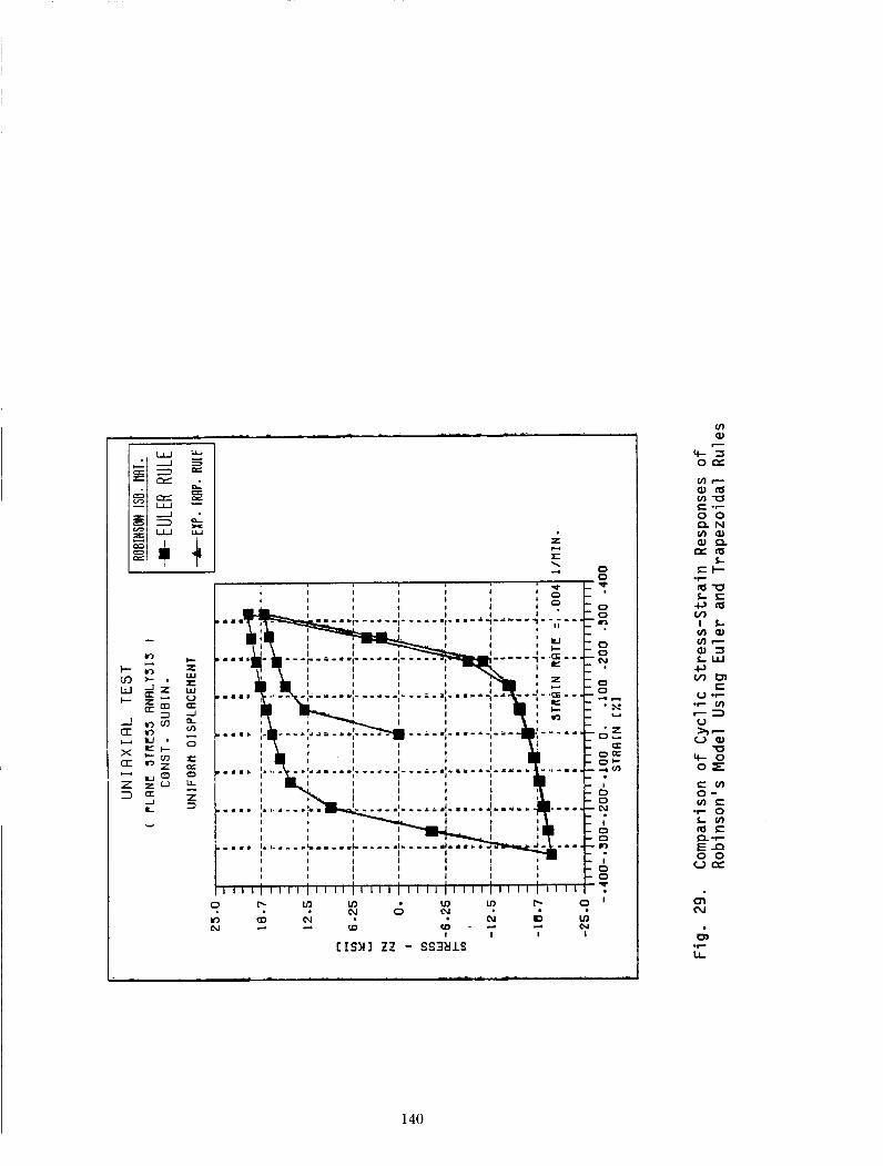
I- m W I-
-1 (I
X U
a c(
Z 3
U
P 0 0 a-J
0 0 c'! 0 0 -I-
' S
' 2 01 U
O + 4 m
0 0
I 0 0 c)
I 0 0
u
oa
I
Y
w
CISWI zz - SS3tllS
u) a,
140

I -
I -
-I W cl 0 t
OL W
m 5 H m 0 (Y
E m a m
0 m
cn LL .r
141

W b
w 0
W I- r
w t- a a t- z W u z 0 V
0 0 0 0 Ln 0 kY 0 N 0
I
0 a 0 Ln 0
0 0 u)
N 0
ln r( P- a 0 0 @ r-
0 ln 0
I I I
C N I l 2 - dSIO
L 0 9-
142
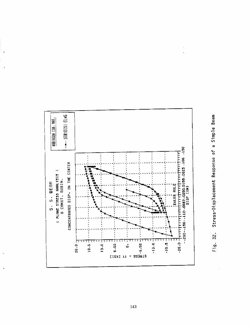
0 m
E lu a, m a,
m re 0
a, m E: 0
m a, CY
n
c, S a, E Q) V m c P m .r n I v) v) a, L c, v)
N m
143

.I -. 0
I I I I I I I
az W I- r w 0
W I c z Y
e VJ
0
0 w c
L
In In ? 9 vi PJ In 0 I N I I I I
N c.
Fi 0
(D
4 ? Y In mY
N
CISUJ A A - SS3YlS
5 W m -0 a, c, L 0 n P 3
WJ
h c
p. E .r WJ
W r c, S .I-
2 0 c, v)
I v) v) W L c, WJ
.r
144

I
- I
a W I- = W V
W I I-
5 p. v)
0
0 W c
I
a a c z W u z 0 V
, ' f :
? 4 I- 0 - c*l
I I
? N - c(
I I I I I I
UY 0 0 0 9 Y ? O - 9 Y
W I-
0
hl
CISMI AI - SS3UlS
u)
13 N 0
0 c1 * 0
n I- C)
0= 0- CI
9
4
?E
o w
Ne 9 0 D d z D I- ' 0
9 ' 0
c, E: a E u m P v)
7
.r n c, S m c, v) S O 0
L al 7Y S => E m a m m E: .r
E: 0
CI m X m a CY v) v) a L c, v)
.r
F
e- m
a,
LL .r
145

P(MPo)
I I I 1
I I I
m t(hr1 0.0028 84.44
F i g . 35. A Thick Wall'Cylinder
146

7.5
5 -0
2.5
B Cl Case A 8 Solution from (80) B g Case B Q Q Case C 00 Case 0
A h
W
A -4 9 0
f 0.001 1 I I
0.00 0.25 0.50 0.75 1.00 2
Time (hr.1 x IO
Fig. 36. Radial Displacement at the Outer Wall o f the Cylinder with Different Incrementing
Schemes
147

I
Typical Node 0 't
Z
/ X
e 2 2
( a Geometry, Displacement , a n d Fiber Basis
S
( b 1 Typical Lamina Coordinates and In-piane Skewness
Fig. 37 . Typical Element HMSHS
148

c
C E I Z D q H
E
'0 - Y
U
Center Displacement (mm)
F i g . 38. A Clamped Square Plate Under Uniform Load
149

0
P
R = 100 L I R = 2 R / h = I O 0
E = 3 x i 0 4 v = 0 . 3
0 0 / -QI HMSHS ( I6 x 16 mesh) --&- Q g - U R I (4x4 mesh)
I 1 1 i i /
4 6 8 10 12 2
Deflection under load, uc
F ig . 39. A Pinched Cylinder With R ig id Diaphragms
150

Radius = I O Thickness = 0.04
E = 6.825 x 10 v =0.3
c 5 - m
a - >
a Y
2 4-
a C
0
U a U 0
-I
0 v)
c
-
0 3- c
c
. 94s (I6 x I6 mesh) and HMSHS (lox I O mesh)
- _ _ Q 4 S (8 x 8 mesh) and HMSH5 ( 8 x 8 mesh
- a a v) -
* 20 40 60 80 too
Load,F
F i g . 40. A Pinched Hemispherical Shell
151

'm
17. Key Words (Suggested by Author@)) 18. Distribution Statement
FEM; Finite element; Anisotropic materials; Composite materials; Laminates; Viscoplastic; Constitutive models; Integration techniques; Mixed elements
Unclassified - Unlimited Subject Category 39
Report Documentation Page __
1 Report No
NASA CR-185120 2. Government Accession No.
7 . Author(s)
A.F. Saleeb, T.Y.P. Chang, T. Wilt, and I. Iskovitz
9 Performing Organization Name and Address
University of Akron Department of Civil Engineering Akron, Ohio 44325
2 Sponsoring Agency Name and Address
National Aeronautics and Space Administration Lewis Research Center Cleveland, Ohio 44135-3 191
5 Supplementary Notes
~~
3. Recipient's Catalog No.
5. Report Date
July 1989
6. Performing Organization Code
8. Performing Organization Report No.
None
10. Work Unit No.
505-63-3 1
11. Contract or Grant No.
NAG3-901
13. Type of Report and Period Covered Contractor Report Final
14. Sponsoring Agency Code
Project Manager, Steven M. Arnold, Structures Division, NASA Lewis Research Center.
6. Abstract
This report outlines the research work performed during the past year on finite element implementation and computational techniques pertaining to high temperature composites. In the present research, two main issues are addressed: efficient geometric modeling of composite structures and expedient numerical integration techniques dealing with constitutive rate equations. In the first issue, mixed finite elements for modeling laminated plates and shells have been examined in terms of numerical accuracy, locking property and computational efficiency. Element applications include (currently available) linearly elastic analysis and future extension to material nonlinearity for damage predictions and large deformations. On the material level, various integration methods to integrate nonlinear constitutive rate equations for finite element implementation have been studied. These include explicit, implicit and automatic subincrementing schemes. In all cases, examples are included to illustrate the numerical characteristics of various methods that have been considered.
20. Security Classif. (of this page) 21. No of pages 22. Price' I Unclassified I 157 1 A08 9. Security Classif. (of this report)
Unclassified
'For sale by the National Technical Information Service, Springfield, Virginia 221 61 NASA FORM 1626 OCT 86