on at '?? 5 m - marin · on at '?? 1/c^-^u^5 m ... ship fixed vertical wave probe at the...
TRANSCRIPT

on At '?? 1/c - U^M
5 W-lfc
A NEW METHOD FOR THE PREDICTION OF
NON-LINEAR RELATIVE WAVE MOTIONS
Bas Buchner
Maritime Research Institute Netherlands
ABSTRACT The problem of green water on the bow decks of floating offshore
production units in large survival waves is an important design problem. An accurate description of the relative wave motions around the bow is important for the prediction of green water on the deck. In the paper a new method is presented to predict these relative wave motions, which are highly non-linear. Input for the method is the calculation of the relative wave motions in front of the bow with linear (3D) diffraction theory. Based on this input the proposed method is able to account for the non-linearities which occur as a result of the non-linearity in the waves, the influence of the above water hull shape (bow flare) and the effect of green water on deck on the ship motions. The method is based on a modification of the Raleigh distribution and allows a fast evaluation of the effect of the above water hull shape (bow flare angle and freeboard height) on the relative wave motions. The prediction of the extreme relative wave motions can be used for the prediction of the required bow height for dry fore decks or to determine the maximum freeboard exceedence as input to the study of green water on the deck.
NOMENCLATURE a-f
fb
H. L Me
M (
P(r) P(r>R) r R s
TP
z P T
parameters in new expression for probability of exceedence of relative wave motions, dependent on wave period and bow flare angle freeboard height from still waterline to top bulwark in m significant wave height in m ship length between perpendiculars in m wave exciting moment in kNm green water moment in kNm probability of occurrence in percent/100 probability of exceedence in percent/100 relative wave motion at centreline bow in m extreme value in relative motions in m standard deviation peak period of wave spectrum in s local vertical motion in m value in expression for probability of exceedence factor in expression for probability of exceedence
co = wave frequency in rad/s £ = wave elevation in m
X = deep water wave length in m
INTRODUCTION With the trend to use Floating Production Storage and Offloading
(FPSO) units in increasingly harsh environments, the problem of solid green water on the bow (or deck wetness) becomes an important design aspect. Due to the weathervaning characteristic of turret moored systems the bow of an FPSO is always exposed to the waves. Recent experience with FPSOs at the North Sea confirmed that green water loading can cause serious damage in the bow region. Because green water loading is a major aspect in the safety of FPSOs, it should be taken into account in the design. This requires an optimum design of the hull shape and the (protecting) structures at the deck.
However, due to the complex nature of the green water phenomena, there are no state-of-the-art methods that can predict green water accurately and efficiently. In recent years the author carried out extensive research on the subject of green water and FPSOs (Buchner, 1995/1996). The research focused in the first place on the description of the occurring phenomena. Based on this research it is presently investigated if new numerical methods can be used to predict the complex and non-linear phenomena green water problem (Buchner and Cozijn, 1997, Ortloff and Krafft, 1997). However, these numerical methods still have significant limitations and drawbacks. Their capability to give reliable predictions is not clear yet, they are sometimes very sensitive to small changes in the input, they require heavy computational equipment and they still need extensive validation with model tests after their development. This type of methods is not expected to be reliable design tools for green water prediction on FPSOs for numbers of years.
To take into account the aspect of green water loading in new designs of FPSOs for harsh environments, the Joint Industry Project P(P)SO Green Water Loading' has been carried out with wide support of the industry. The JIP was based on extensive model tests and computations. It covered a wide range of topics: from relative

wave motion prediction to the impact loading on structures with different structural shapes at the deck.
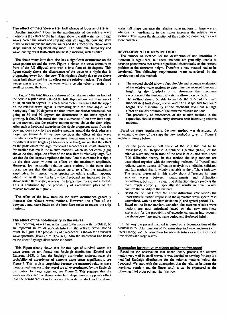
This paper -based on the JIP results- focuses on the input to the green water problem: the prediction of the strong non-linear relative wave motions around the bow. A new method will be presented which can be used to predict the required bow height for dry foredecks, or to predict the amount of water on the deck. The new method is developed and validated with a large number of model tests with a full elliptical bow. The wateriine of this bow is given in the Figure 1 and its main particulars are given in Table 1. This full elliptical bow represents the base case for both new designs as well as traditional tanker bows. Most of the existing tankers can be seen as a variation (in flare) of this base shape. The effect of the bow shape above the still wateriine was investigated too. Keeping the underwater part of the ships constant, bow flare angles (with the vertical) of 0, 10, 30 and 50 degrees were investigated. The body plan with a bow flare of 30 degrees is shown in Figure 1. The bow flare angle was defined in a plane perpendicular to the wateriine.
Tests were carried out in regular as well as irregular waves. Regular wave tests were carried out for different wave lengths (X/L=0.75, 1.0 and 1.25) and wave heights (50-115% of a reference wave height. For 50% and 70% there is no water on the deck). Irregular wave tests were carried out in a significant wave height of 13.5 m with spectral peak periods 12,14 and 16 s (JONSWAP).
The relative wave motions (r) in this paper were measured with a ship fixed vertical wave probe at the centreline of the ship, 1.0 m in front of the bulwark (see Figure 1). The ship was moored in a horizontal soft spring mooring system (stiffness in x-direction 430 kN/m) and was free to move in six degrees of freedom. The water depth was 150 m.
s is the standard deviation of the linear motion response in the wave spectrum.
OBSERVATION OF NON-LINEARITIES However, it was found in this and previous studies (Buchner,
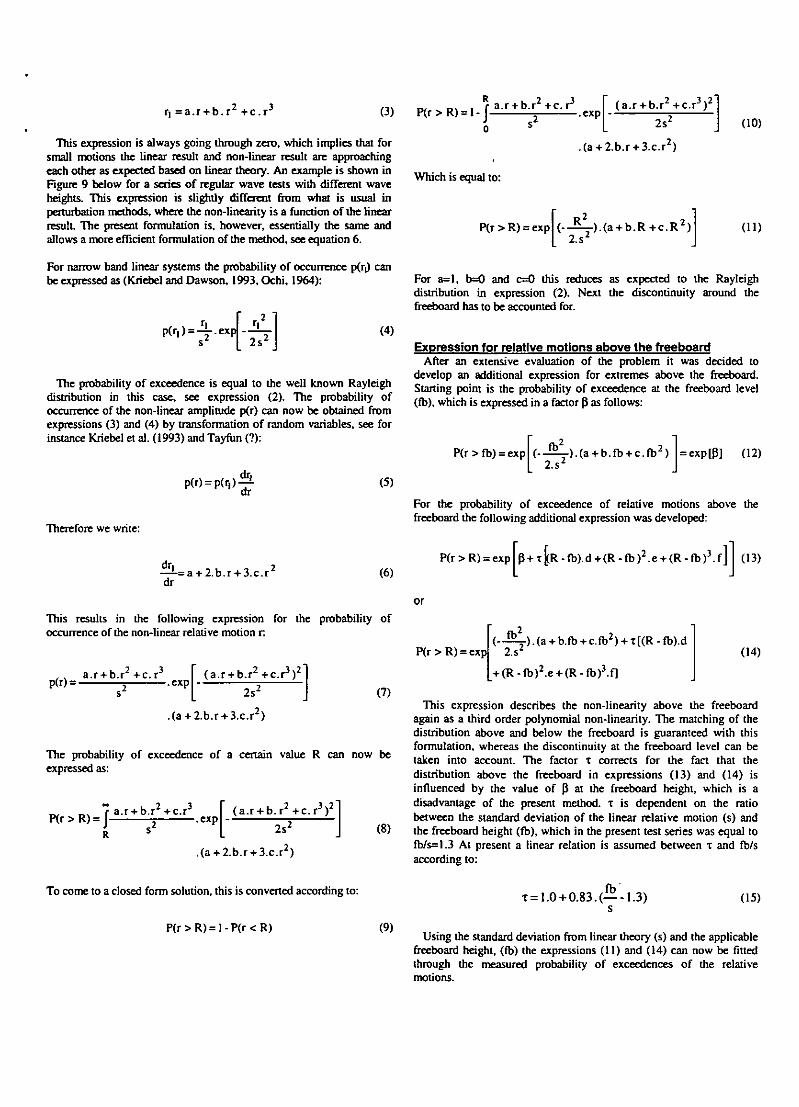
1995/1996) that the actual relative wave motions in large survival waves are highly non-linear. Figure 2 shows the probability of exceedence of the relative wave motions in front of the bow for a bow flare angle of 30 degrees for the different irregular waves (Peak periods Tp of 12, 14 and 16 s). In the figures both the measured probability of exceedence as well as the linear narrow banded Rayleigh distribution according to expression (2) are shown.
As can be seen from this Figure, the measured distribution deviates significantly from the Rayleigh distribution. The Rayleigh distribution underpredicts the probability of exceedence of small crests, but overpredicts the probability of exceedence of the larger crests. The difference between the Rayleigh and measured distributions is dependent on the wave period. In short waves the differences are larger than in long waves. A close study of the measured distributions shows that they all have a clear discontinuity at the freeboard height. This aspect is important in the new method that is developed in this study. The non-linearity is confirmed by the comparison between measured and calculated pitch and relative wave motion RAOs in Figure 3. The figure shows the calculated response as well as the measured response in regular waves of different amplitudes (50%-l 15% of a reference wave height of 100%). In general the measurements approach the calculations when the wave amplitude decreases, which confirms the validity of diffraction analysis for small wave heights.
The physical background of the observed non-linearities can be related to the effect of:
RELATIVE WAVE MOTIONS The relative wave motions around the bow are the input to the green
water problem. They should therefore be predicted accurately to obtain a reliable prediction of green water occurrence and loading.
The relative motions of the waves with respect to the ship are defined as the difference between the local vertical vessel motion z and the local wave motions C, according to:
r = ; - z (1)
FPSO motions and relative wave motions are nowadays generally calculated with linear diffraction analysis. Diffraction analysis is based on the main assumptions of small sinusoidal waves and vessel motions. The interaction between structure and fluid is limited to the part below the still wateriine, which implies that the bow shape above the wateriine is considered to be vertical ('wall sided', no bow flare).
The Response Amplitude Operators (RAOs) from diffraction theory can be used to determine the linear response in an irregular wave spectrum. Applying the assumptions of a narrow banded linear motion response to Gaussian distributed waves, Ochi (1964) developed the following expression for the probability of exceedence P of a certain value R of a peak of the relative wave motions:
- die water on deck on the ship motions - the above water hull shape at bow and stem - die non-linearities in the waves
The effect of the water on deck on the ship motions In (Buchner, 1995b) a study was carried out to investigate the
sensitivity of the pitch motions for water on the deck. The load of the water on the deck has a large moment arm with respect to the centre of gravity, resulting in a significant green water moment Mg. In this study it was found that the pitch motion changes significantly as a result of the green water in short waves, whereas the effect in the longer waves is small. This is due to the ratio between the wave exciting moment M6 and the moment due to the green water Mg. This ratio is large for the longer waves and small for the shorter waves. These results are supported by the results of the present study.
Based on the measurements of the water heights on the deck at three positions and the vertical acceleration of the deck at the related positions, the green water moment M ( was estimated for three regular waves with different ratios between wave length X and ship length L, In the Table 2 the maximum values of M ( and the linear wave moment Me are summarised. It will be clear from these numbers that the green water moment can have a large effect on the ship motions, especially in short waves. Its final effect is dependent on the phase of this moment compared to the ship motions and wave exciting moment (Buchner, 1995b).
p ( r>R) = exp 2sJ
(2)
The effect of the above water hull shape at bow and stern Another important aspect in the non-linearity of the relative wave
motions is the effect of the hull shape above the still wateriine in large waves. When the waves and ship motions are large, the bow and stem of the vessel are pushed into the water and the effect of the above water shape cannot be neglected any more. The additional buoyancy and wave loading result in an effect on the ship motions, such as pitch.
The above water bow flare also has a significant disturbance on the wave panem around the bow. Figure 4 shows die wave contours in front of the full elliptical bow with a bow flare of 30 degrees. This figure clearly shows the disturbance of the wave in a ripple dial is progressing away from the bow. This ripple is clearly due to the above water hull shape and has its effect on the relative motions. The flared wedge that is pushed in die water with a certain velocity results in a swell up around the bow.
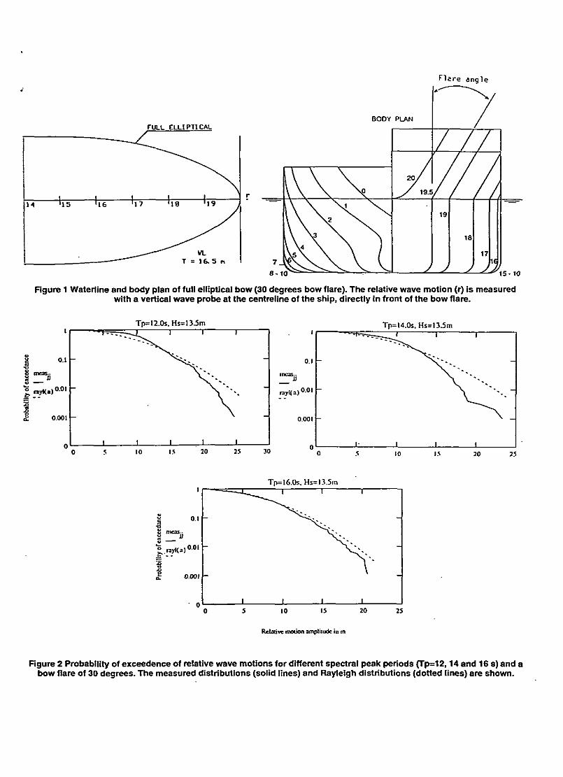
In Figure 5 the time traces are shown of die relative motion in front of the bow in regular wave tests on the full elliptical bow with flare angles of 10,30 and 50 degrees. It is clear from these time traces that the ripple on the relative wave signal is increasing with the flare angle. With hardly any flare (10 degrees) the time traces are almost sinusoidal, but going to 30 and 50 degrees the disturbance in the main signal is growing. It should be noted that the disturbance of the bow flare stops at die moment that the relative motion comes above me deck edge. After such a freeboard exceedence the ripple progresses away from the bow and does not effect the relative motions around die deck edge any more, see Figure 4. If we now consider the effect of this wave disturbance on me peaks in die relative motion time traces in Figure 6 for different wave heights (30 degrees bow flare), we see that the effect on the peak values for large freeboard exceedences is small. However, for smaller maxima in the relative motions, which do not come (high) above the deck edge, me effect of the bow flare is relatively large. We see that for the largest amplitude the bow flare disturbance is a ripple on the time trace, without an effect on the maximum amplitude. However, for the smaller relative wave motions in the other lime traces we see that the disturbance starts to effect the maximum amplitudes. In irregular wave spectra something similar happens, where the small maxima below die freeboard are increased by die above water flare angle, whereas the larger maxima are not affected. This is confirmed by the probability of exceedence plots of die relative motions in Figure 2.
The effect of die bow flare on the wave disturbance generally increases die relative wave motions. However, the effect of the buoyancy and wave loads on die bow flare tends to reduce the ship motions.
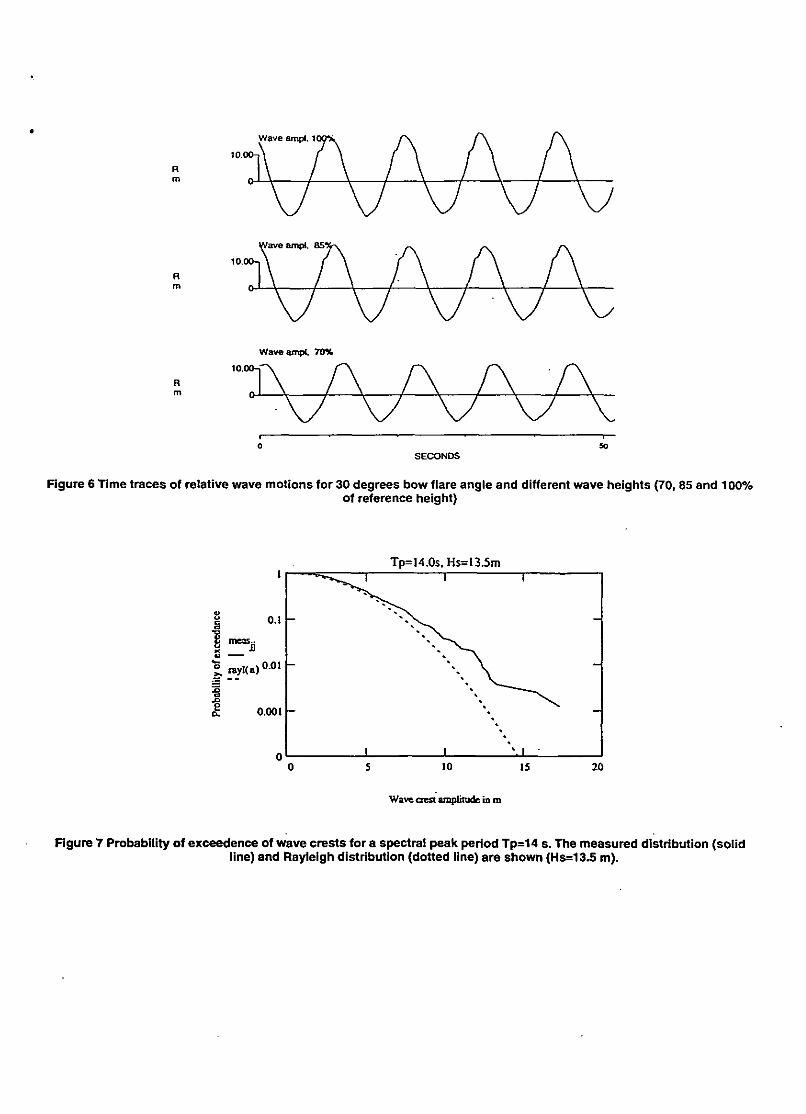
The effect of the non-llnearitv In the waves The incoming waves can, as the input to the green water problem, be
an important source of non-linearities in die relative wave motion result In Figure 7 the probability of exceedence is shown for a survival wave spectrum (Hs=13.5 m, Tp=14 s). Also the theoretical line based on the linear Rayleigh distribution is shown.
This Figure clearly shows dial for diis type of survival waves the wave crests do not follow the Rayleigh distribution (Kriebel and Dawson, 1993). In fact, me Rayleigh distribution underestimates die probability of exceedence of extreme wave crests significanüy, see Figure 7. This result is surprising because me measured relative wave motions wiui respect to the vessel are all overestimated by the Rayleigh distribution for large extremes, see Figure 2. This suggests that the water on deck and die above water hull shape have an opposite effect dian the non-linearities in the waves. The water on deck and the above
water hull shape decrease die relative wave motions in large waves, whereas die non-linearity in die waves increases me relative wave motions. This makes die description of the combined non-linearity even more complex.
DEVELOPMENT OF NEW METHOD The number of methods for die description of non-linearities in
literature is significant, but these metiiods are generally unable to describe phenomena that have a significant discontinuity as the present problem at die freeboard height. Therefore a new metiiod had to be developed. The following requirements were considered in the development of this method:
a The method should allow a fast, flexible and accurate evaluation of die relative wave motions to determine the required freeboard height for dry foredecks or to determine the maximum exceedence of the freeboard if water is allowed on die deck.
b The method should be able to include die effect of the main (underwater) hull shape, above water hull shape and freeboard height. The discontinuity at die freeboard level has a large effect on die distribution of the extreme relative motions.
c The probability of exceedence of die relative motions in die expression should continuously decrease with increasing relative motions.
Based on diese requirements die new metiiod was developed. A schematic overview of the steps die new method is given in Figure 8 and die summary below.
1. For die (underwater) hull shape of die ship tiiat has to be investigated, the Response Amplitude Operator (RAO) of the relative wave motion in front of die bow is calculated widi linear (3D) diffraction theory. In this method the ship motions are determined together with me incoming, reflected (diffracted) and radiated waves. Linear diffraction analysis is a reliable, validated and fast metiiod that is widely available in die offshore industry. The results presented in this study show differences in large survival waves between measurements and diffraction calculations, but still it is clear tiiat diffraction dieory predicts the main trends correctly. Especially die results in small waves confirm the validity of die mediod.
2. Based on the RAO from the linear diffraction calculations the linear relative motion response in die applicable wave spectrum is determined, with its standard deviation (s) and typical period (T).
3. Based on die linear standard deviation, die extreme relative wave motions are now calculated based on die new non-linear expression for the probability of exceedence, taking into account the above bow flare angle, wave period and freeboard height.
In this way the present mediod is based on a decomposition of the problem in the determination of die main ship and wave motions (with linear dieory) and die correction for non-linearities as a result of local flow effects and large waves.
Expression for relative motions below the freeboard Based on the observation mat linear dieory predicts die relative
motion very well in small waves, it was decided to develop for step 3 a modified Rayleigh distribution for die relative motions below die freeboard. We start with the assumption that die relation between die non-linear result r and die linear result rt can be expressed as die following third order polynomial function:
f] = a . r + b . r 2 + c . r 3 (3)
This expression is always going through zero, which implies that for small motions the linear result and non-linear result are approaching each other as expected based on linear theory. An example is shown in Figure 9 below for a scries of regular wave tests with different wave heights. This expression is slightly different from what is usual in perturbation methods, where the non-linearity is a function of the linear result. The present formulation is, however, essentially the same and allows a more efficient formulation of the method, see equation 6.
P ( r>R) = l - | a.r + b . r 2 +c. r 3
Which is equal to:
.exp (a . r + b . r 2 + c . r 3 ) 2
2s'
P(r > R) = exp
.(a+2.b.r + 3 .c . r )
(--*—).(a + b . R + c . R 2 ) 2.s2
(10)
(11)
For narrow band linear systems the probability of occurrence p(r,) can be expressed as (Kriebel and Dawson, 1993, Ochi, 1964):
p ( r i ) = - r e x P 2s '
(4)
The probability of exceedence is equal to the well known Rayleigh distribution in this case, see expression (2). The probability of occurrence of the non-linear amplitude p(r) can now be obtained from expressions (3) and (4) by transformation of random variables, see for instance Kriebel et al. (1993) and Tayfun (?):
dr, p(D = p(r,)-i-
dr (5)
Therefore we write:
—!-=a + 2.b.r + 3.c.r' dr
(6)
This results in the following expression for the probability of occurrence of the non-linear relative motion r.
P(r) = a.r + b.r + c.r
.exp (a.r + b . r 2 +c . r 3 ) 2
2sJ (7)
.(a + 2.b.T + 3.c.rl)
The probability of exceedence of a certain value R can now be expressed as:
P(r>R) = ] a.r + b.r + c.r .exp
(a . r + b . r 2 + c . r 3 ) 2
2sJ (8)
.(a + 2.b.T + 3.c.r*)
For a=l, b=0 and c=0 this reduces as expected to the Rayleigh distribution in expression (2). Next the discontinuity around the freeboard has to be accounted for.
Expression for relative motions above the freeboard After an extensive evaluation of the problem it was decided to
develop an additional expression for extremes above the freeboard. Starting point is the probability of exceedence at the freeboard level (fb), which is expressed in a factor P as follows:
P(r > fb) = exp ( - - ^ - ) . ( a + b.fb + c.fb2) 2.s2
= exp[P] (12)
For the probability of exceedence of relative motions above the freeboard the following additional expression was developed:
P(r > R) = exp p+TfcR-fb).d+(R-fb)2 .e + (R-fb) 3 . f ] (13)
or
P(r>R) = exp 2.s ( - ^ T ) . ( a + b.ib + c.fb2) + T[(R-fb).d
+ (R-fb)2.e + (R-fb)3.f]
(14)
This expression describes the non-linearity above the freeboard again as a third order polynomial non-linearity. The matching of the distribution above and below the freeboard is guaranteed with this formulation, whereas the discontinuity at the freeboard level can be taken into account. The factor x corrects for the fact that the distribution above the freeboard in expressions (13) and (14) is influenced by the value of p at the freeboard height, which is a disadvantage of the present method, T is dependent on the ratio between the standard deviation of the linear relative motion (s) and the freeboard height (fb), which in the present test series was equal to fb/s=1.3 At present a linear relation is assumed between T and fb/s according to:
To come to a closed form solution, this is converted according to:
P(r > R) = 1 - P(r < R) (9)
T=1.0 + 0.83.(—-1.3) s
(15)
Using the standard deviation from linear theory (s) and the applicable freeboard height, (fb) the expressions (11) and (14) can now be fitted through the measured probability of exceedences of the relative motions.

In this way the parameters a-f were determined for each bow flare angle (0, 10, 30 and 50 degrees) and peak period of the spectrum. In Figure 10 below an example is shown of a measured and fitted probability of exceedence for a bow flare angle of 30 degrees. This figure makes clear that the chosen expressions are able to describe successfully the observed non-linear distributions with their different behaviour above and below die freeboard.
Validation of developed expression Going back to the sequence in Figure 8, die developed method should
now be able to predict the non-linearity in other situations with other hull dimensions or underwater shapes, but with similar above water flare angles. For this validation two cases were used with a bow flare of 30 degrees (Tp=14.0s):
• Case 1 with a different stem but with a same bow and bow flare angle - Case 2 with an enlarged freeboard height
In Case 1 there is a significant variation in standard deviation s in the linear diffraction theory motions, from 8.03 m for the original (tanker type) stem to 7.17 m for the full (box type) stem. In Case 2 there was a significant variation in freeboard height (fb) from 10.5 to 15.5 m, with the same linear standard deviation (the situation below the still waterline is identical).
The predicted and measured distributions for Case 1 are shown in Figure 11, together with the Rayleigh distribution. It shows a good comparison between measurements and predictions. In Figure 12 a comparison is made between the original distribution (10.5 m freeboard) and die distribution with enlarged freeboard height from Case 2 (15.5 m freeboard). This Figure confirms a general observation in tests of FPSOs: if after a test with much green water on me deck an enlarged freeboard is applied to prevent green water, the relative motions seem the increase too. The enlarge freeboard height is not completely effective. This is due to the reduced amount of water on the deck, the reduced lowering of the wave height around the bow due to a reduced flow onto the deck and the increased swell up effect of the flare on the wave motions. In Figure 13 it is shown that the new method is able to predict this effect of the increased freeboard accurately. The comparisons in Case 1 and 2 make clear that the chosen expression is able to predict the non-linear distribution of extremes with a good accuracy.
Effect of current Current can have a significant increasing effect on the green water
on FPSOs (Buchner, 1995a). This is not due to the effect of the current velocity on the flow onto die deck, but a result of the increased relative wave motions in current (when it is collinear with the waves). This effect is mainly due to the increased pitch motions in current. These increased pitch motions are due to the increase in wave length if the same earth fixed wave frequency is used in current (Buchner, 1995a). Due to this increase in wave length, the wave exciting forces on the tanker increase, whereas the wave period comes closer to the pitch natural period of the F(P)SO. This combined effect, taking into account the influence of the current on added mass and damping, results in the increase of vessel motions. These effects can be calculated with linear theory, as was shown for instance by Huijsmans and Dallinga (1983) and Beck and Loken (1989).
Using the linear RAOs in current from mis method, the linear standard deviation was determined in a current speed of 2.0 knots. This standard deviation was included in expressions (11) and (14) for a bow flare angle of 30 degrees (determined without current). In
Figure 14 the predicted and measured probabilities of exceedence are shown for the 2.0 knots current situation. The predicted probability of exceedence shows a very good comparison widi the measurement. This confirms that the presently proposed method can be used to take into account the effect of current on die relative motions of the bow.
APPUCATION In die Joint Industry Project the expressions were determined for
bow flare angles of 0, 10, 30 and 50 degrees. Spectral peak periods of 12, 14 and 16 s were considered. As an example Figure 15 shows the probability of exceedence based on expressions (11) and (14) for all bow flare angles with a freeboard height of 10.5 m and a spectral peak period of 14.0 s. The related linear Rayleigh distribution is shown too.
With the new expressions for the probability of exceedence design values for the maximum relative wave motions can be determined, such as the Most Probable Maximum (MPM) value. The MPM value is the relative wave motion value for which the following relation applies:
PCr>RMPM> = 17 <16)
N is die total number of relative motion maxima in the total storm duration. Taking die situation in Figure 15 and assuming 100 wave oscillations (N=100, P=0.01) we find the overview of Most Probable Maximum relative motions and freeboard exceedences for this situation in Table 3, P(r>MPM=0.01). It can be concluded that the Rayleigh distribution in this case is conservative with respect to die measurements. The results also show the influence of the bow flare angle on the relative wave motions.
Widi die developed expressions it is possible to study the effect of design decisions with respect to die above water hull shape (bow flare angle and freeboard height) on the relative wave motions. It should be noted that die bow flare angle not only influences the relative wave motions. It also influences the relation between the exceedence of the freeboard and die water height on die deck, the water velocity over the deck and die impact loading on structures are influenced by the bow flare angle. This will be studied and presented in a future paper.
CONCLUSION Based on the results presented in this paper it can be concluded that
the developed meüiod is very useful for the prediction of the extreme relative wave motions. These can be used for the prediction of the required bow height for dry fore decks or to determine die maximum freeboard exceedence as input to the study of the green water behaviour on die deck. It allows a fast evaluation of the effect of the above water hull shape (bow flare angle and freeboard height) on the relative wave motions.
ACKNOWLEDGEMENTS The author wishes to thank the participants of the Joint Industry
Project 'F(P)SO Green Water Loading' for die cooperation in die project and the permission for publication of mis paper ABB Offshore Technology, Bluewater Engineering, BP, Chevron, Conoco, Exxon, FMC Sofec, Germanischer Lloyd, Health & Safety Executive (HSE), Maersk Contractors, Mobil, Samsung Heavy Industries, SBM, Gusto Engineering, Shell and Texaco. Gert van Ballegoyen of MARIN is acknowledged for his continuous support in die analysis of die results.

REFERENCES Beck, F.R. and Loken, A.E., 1989. 'Three-dimensional Effects in Ship Relative-Motion Problems," Journal of Ship Research, Volume 33, No. 4, pp. 261-268.
Buchner, B., 1995a, 'The Impact of Green Water on FPSO Design," OTC Paper 7698, OTC 1995, Houston.
Buchner, B., 1995b, "On the Impact of Green Water Loading on Ship and Offshore Unit Design," PRADS "95, Seoul.
Buchner, B., 1996, 'The Influence of the Bow Shape of FPSOs on Drift Forces and Green Water," OTC Paper 8073, OTC 1996, Houston.
Buchner, B. and Cozijn, J.L., 1997, "An Investigation into the Numerical Simulation of Green Water," Boss"97, Delft.
Huijsmans, R.H.M. and Dallinga, R.P., 1983, "Non-linear Ship Motions in Shallow Water," International Workshop on Ship and Platform Motions, Berkeley.
Kriebel, D.L. and Dawson, T. H., 1993, "Nonlinearity in Wave Crest Statistics," 2nd Intl. Symposium on Ocean Wave Measurement and Analysis, pp. 6175.
Ochi, M.K., 1964, "Extreme Behaviour of a Ship in Rough Seas Slamming and Shipping of Green Water," Annual Meeting SNAME.
Ortloff, C.R. and Krafft, M.J., 1997, "Numerical Test Tank: Simulation of Ocean Engineering Problems by Computational Fluid Dynamics," OTC 8269, OTC 1997. Houston.
Tayfun, M.A., "Narrow Banded Nonlinear Waves.' Geophysical Research, Vol. 85. No. C3, pp. 1548-1552.
Journal of
Table 1 Main particulars of ship
Length between perpendiculars 260.34 m Beam 47.09 m Draft (even keel) 16.50 m Freeboard at bow (including bulwark) 10.5 m Displacement 168870 t CoG above keel 14.14 m CoG forward of midships 5.69 m Longitudinal radius of gyration 69.80 m
Table 2 Estimated green water moment and linear wave moment as function of ratio wave length to ship length
Ratio wave length to ship length Estimated green water moment Mf in kNm
Linear wave moment Me in kNm
1.25 1.0
0.75
7.13.10" 6.44. 106
4.82. 106
2.82.10' 1.37.107
4.82.106
Table 3 Predicted most probable maximum relative wave motions and freeboard exceedences (fb=10.5m) with different bow flare angles for a spectral peak period of 14.0s
Rayleigh (linear)
Odeg. lOdeg. 30 deg. 50 deg.
MPM Relative wave motions
24.4 m 20.2 m 19.7 m 19.1 m 18.5 m
MPM Freeboard exceedence
13.9 m 9.7 m 9.2 m 8.6 m 8.0 m
Flare angle
FULL ELLIPTICAL
i I I i I | 14 >15 >16 ' l 7 '18 '19 j
""""^ VL T = 1 6 . 5 n
8-10
Rgure 1 Wateriine and body plan of full elliptical bow (30 degrees bow flare). The relative wave motion (r) is measured with a vertical wave probe at the centreline of the ship, directly in front of the bow flare.
£ tneas» 3 0
£, nyKa) o.oit-
o.ooi r-
Tp=l2.0s, Hs=13.5m T
rayKa)
' Tp=14.0s. Hs=13.5m
' " e r s ^ ^ - r — ' * 1
0.1 NT"*. "-.,
—
j 0.01 \ -,
0.001
1- 1 1 1
-
10 15 20 25
It
_. rayKa)
O . l H
o.oi H
0.001 r~
0
Tp=16.0s. Hs=l3.5m T
Relative motion amplitude in m
Rgure 2 Probability of exceedence of relative wave motions for different spectral peak periods (Tp=12,14 and 16 s) and a bow flare of 30 degrees. The measured distributions (solid lines) and Rayleigh distributions (dotted lines) are shown.

— Calculated CD Measured nSV. wave ampl. O Measured WOV. wave ampl. e. Measured 6S*A wave a m p i
Measured 70V. w a v e ampl Measured 50V. w a v e ampl
X,
0.S-
/S\.
/ I K
0.0 0 5 1.0
W a v e frequency in rad/s
1.5
Calculated Measured 115% wave ampl Measured ttOK wave empL Measured BSH wave «mpt.
Measured. 70% wave «mpL Measured 50% wave ampl
OS 1.0 Wave frequency h rad/s
Rgure 3 Pitch and relative wave motion Response Amplitude Operators (RAOs) calculated with linear diffraction theory (solid lines) and measured in different regular wave heights. For each wave frequency different wave heights were tested to investigate non-linearities. The wave height varied from 50 to 115 % of a reference wave height With 50 and 70% there
was no water on the deck.

5.0 m
Watcrlinc
Figure 4 Wave contours of green water flow onto the deck, visualised with a plate at the centreline of the deck. Water contours are shown with time steps of 0.31 s for a bow flare angle of 30 degrees.
FLARE 50 deg
SECONDS
Figure 5 Time traces of relative wave motions for bow flare angles of 10,30 and 50 degrees
Wave
Waveampl. 70%
- r -so
SECONDS
Figure 6 Time traces of relative wave motions for 30 degrees bow flare angle and different wave heights (70, 85 and 100% of reference height)
Tp=14.0s. Hs=13.5m
I "^jj
Hi»*.)0*1
0.0011-
Wave crest amplitude in m
Figure 7 Probability of exceedence of wave crests for a spectral peak period Tp=14 s. The measured distribution (solid line) and Rayleigh distribution (dotted line) are shown (Hs=13.5 m).

\
Underwater hull shape Wave spectrum Bow flare angle, freeboard
1 '
RAO
i '
s,T
*'
Linear RAO Motion response in wave spectrum
s,T Prediction non-linear extremes
' m i x Motion response in wave spectrum
w
Prediction non-linear extremes
Figure 8 Schematic overview of the proposed method with input and output
£ linear(0
§ 1'! f(r) 10 - '
Measured R value
Figure 9 Linear predicted relative wave motion versus measured relative wave motions for different regular wave heights. A linear relation is indicated (solid line) as well as a description of the non-linearity with a third order polynomial
(dotted line)
o.i -
o rayl(r) 0.01
3 polytot(r)
0.001 -
—-r — — * * * ! 1 1
- ^ v ^ ~*~ „ -
\ N ***-w
V x
I 1 1 1
10 15 20 25
Figure 10 The new expression for the probability of exceedence of relative wave motions (dashed line) fitted to the measurements (solid line) for the bow with 30 degrees bow flare and a spectral peak period of 14.0 seconds. Also the
Rayleigh distribution is shown (dotted line).

rayKr)
pred(r)
0.1 -
0.01 -
0.001 -
" " • ^ ^ ^
1
N ^ . ~ - .
\ \ „
VX
\ * \
1
X \
\ \
12.5
r 25
Figure 11 Comparison of predicted relative wave motion with new method (dashed line) with the measurements (solid line) for the situation with modified full stern. Also the Rayleigh distribution is shown (dotted line)
highj
low-
0.01 -
0.001 12.5
Relative motion in m
Rgure 12 Probability of exceedence of relative wave motions with original freeboard height (10.5m, low, dotted line) and extended freeboard height (15.5 m, high, solid line), both with 30 degrees bow flare angle
8 _
Relative wave motion in m
Figure 13 Prediction of relative wave motions with new method for situation with extended freeboard height (dashed line), compared to measurements (solid line). Also the Rayleigh distribution is shown (dotted line).

cwrl . .
Figure 14 Prediction of relative wave motions with new method for current speed of 2.0 knots (dashed line) compared to the measurements (solid line). Also the Raylelgh distribution is shown (dotted line)
prcdO(r)
predKXO
pred30(r)
predS0(r)
rayKO
0.1 -
0.01 -
0.001
• * .
' o -N N (/"""-•v. Rayleigh
\ v \ 0 \ N* \
N'V ^\\-NXV30
\ \ 5 0
10 IS 20 25
Figure 15 Effect of bow flare angle on the relative wave motions in a wave spectrum with peak period 14.0 s and significant height of 13.5 m (freeboard height 10.5 m). Bow flare angles of 0,10,30 and 50 degrees are shown, together
with the Rayleigh distribution