odyssey tta, twe-accu 6-25tr ahu 5-25tr
DESCRIPTION
TRANETRANSCRIPT

Split System Air Conditioners
Odyssey™ — TTA, TWE
Cooling Units — 6 - 25 Tons — 60 Hz Air Handlers — 5 - 25 Tons — 60 Hz
SS-PRC028-ENMarch 2012
Product Catalog

Introduction
Trane’s reputation for providing quality comfort solutions continues with the development of the next generation Light Commercial Odyssey Split Systems.
With wide network availability, flexible applications, installation ease, built-in reliability and easy servicing, Odyssey will meet any number of customer applications. Add to that Trane’s outstanding customer service and you have the formula to make Odyssey the clear choice for continued customer satisfaction.
Wide network availability
A broad distribution network provides owners, maintenance personnel, contractors, etc., the means to get their hands on equipment when they need it. Whether it’s an emergency replacement or a new construction project in its infancy stages, Trane’s Odyssey products meet an array of needs at the right time and right price.
Flexible applications
No matter what the application, Odyssey provides the solution. A broad array of models and tonnages are available with single or dual compressors, single or dual circuits and numerous accessories. Condensing units can be installed on the ground or on a rooftop along with extended piping runs, while air handlers can be free discharge on the ground or horizontally suspended with long duct runs from a ceiling. Should application challenges arise, Odyssey delivers.
Easy to install
Small footprints and low weights combined with factory installed components like TXVs, filter driers, etc., reduce installation time and cost. Colored and numbered wiring and factory tested units make Odyssey the right choice.
Trane and the Trane logo are trademarks of Trane in the United States and other countries. All trademarks referenced in this document are the trademarks of their respective owners.
© 2012 Trane All rights reserved SS-PRC028-EN

Introduction
Built-in reliability
Keeping in mind that productivity only occurs when equipment is operational, Trane has taken the steps to ensure that Odyssey is up and running. Early indicators such as phase/reversal monitors and loss of charge protection provide diagnostics which prevent failure and provide years of worry-free service and operation.
Easy to service
When preventive maintenance or service is required, technicians will find efficient access to both air handlers and condensers. Panels provide complete, easy access coupled with standardized cabinets in which all components are located in proximity. Odyssey’s improved design results in minimum service times and costs.
With these capabilities, Odyssey provides customers high efficiency and superior performance for the best all-around value in the market today.
SS-PRC028-EN 3

4 SS-PRC028-EN
Table of Contents
Features & Benefits . . . . . . . . . . . . . . . . . . . . . . . . . . . . . . . . . . . . . . . . . . . . . . . . . . . . . 5Options . . . . . . . . . . . . . . . . . . . . . . . . . . . . . . . . . . . . . . . . . . . . . . . . . . . . . . 5Other Benefits . . . . . . . . . . . . . . . . . . . . . . . . . . . . . . . . . . . . . . . . . . . . . . . . 6
Standard Features . . . . . . . . . . . . . . . . . . . . . . . . . . . . . . . . . . . . . . . . . . . . . . . . . 6
Variety of Options . . . . . . . . . . . . . . . . . . . . . . . . . . . . . . . . . . . . . . . . . . . . . . . . . . 8Factory Installed Options . . . . . . . . . . . . . . . . . . . . . . . . . . . . . . . . . . . . . . . 8Factory or Field Installed Options . . . . . . . . . . . . . . . . . . . . . . . . . . . . . . . . 9Field Installed Options . . . . . . . . . . . . . . . . . . . . . . . . . . . . . . . . . . . . . . . . . 9
Other Benefits . . . . . . . . . . . . . . . . . . . . . . . . . . . . . . . . . . . . . . . . . . . . . . . . . . . . 10
Accessories . . . . . . . . . . . . . . . . . . . . . . . . . . . . . . . . . . . . . . . . . . . . . . . . . . . . . . . . . . . 12TTA Accessories . . . . . . . . . . . . . . . . . . . . . . . . . . . . . . . . . . . . . . . . . . . . . 12TWE Accessories . . . . . . . . . . . . . . . . . . . . . . . . . . . . . . . . . . . . . . . . . . . . . 13Electric Heaters . . . . . . . . . . . . . . . . . . . . . . . . . . . . . . . . . . . . . . . . . . . . . . 16
Application Considerations . . . . . . . . . . . . . . . . . . . . . . . . . . . . . . . . . . . . . . . . . . . . . 17
Selection Procedure . . . . . . . . . . . . . . . . . . . . . . . . . . . . . . . . . . . . . . . . . . . . . . . . . . . 19
Model Number Descriptions . . . . . . . . . . . . . . . . . . . . . . . . . . . . . . . . . . . . . . . . . . . . 20
General Data . . . . . . . . . . . . . . . . . . . . . . . . . . . . . . . . . . . . . . . . . . . . . . . . . . . . . . . . . . 22
Performance Data . . . . . . . . . . . . . . . . . . . . . . . . . . . . . . . . . . . . . . . . . . . . . . . . . . . . . 26
Controls . . . . . . . . . . . . . . . . . . . . . . . . . . . . . . . . . . . . . . . . . . . . . . . . . . . . . . . . . . . . . . 87ReliaTel™ Controlled Units . . . . . . . . . . . . . . . . . . . . . . . . . . . . . . . . . . . . 87Electromechanical Controlled Units . . . . . . . . . . . . . . . . . . . . . . . . . . . . . 88
Electrical Data . . . . . . . . . . . . . . . . . . . . . . . . . . . . . . . . . . . . . . . . . . . . . . . . . . . . . . . . . 89Condenser Electrical Data . . . . . . . . . . . . . . . . . . . . . . . . . . . . . . . . . . . . . . 89Air Handler (Standard, SZVAV and 2-Speed VFD) Electrical Data . . . . . 91
Jobsite Connections . . . . . . . . . . . . . . . . . . . . . . . . . . . . . . . . . . . . . . . . . . . . . . . . . . 103For Electromechanical Controls . . . . . . . . . . . . . . . . . . . . . . . . . . . . . . . . 103For ReliaTel™ Controls . . . . . . . . . . . . . . . . . . . . . . . . . . . . . . . . . . . . . . . 104
Typical Wiring . . . . . . . . . . . . . . . . . . . . . . . . . . . . . . . . . . . . . . . . . . . . . . . . . . . . . . . . 106
Dimensional Data . . . . . . . . . . . . . . . . . . . . . . . . . . . . . . . . . . . . . . . . . . . . . . . . . . . . . 116
Weights . . . . . . . . . . . . . . . . . . . . . . . . . . . . . . . . . . . . . . . . . . . . . . . . . . . . . . . . . . . . . 138
Mechanical Specifications . . . . . . . . . . . . . . . . . . . . . . . . . . . . . . . . . . . . . . . . . . . . . 141
TTA Condensing Units . . . . . . . . . . . . . . . . . . . . . . . . . . . . . . . . . . . . . . . . . . . . 141Factory Installed Options . . . . . . . . . . . . . . . . . . . . . . . . . . . . . . . . . . . . . 142Field Installed Options . . . . . . . . . . . . . . . . . . . . . . . . . . . . . . . . . . . . . . . 143
TWE Air Handlers . . . . . . . . . . . . . . . . . . . . . . . . . . . . . . . . . . . . . . . . . . . . . . . . 144Factory Installed Options . . . . . . . . . . . . . . . . . . . . . . . . . . . . . . . . . . . . . 145Field Installed Options . . . . . . . . . . . . . . . . . . . . . . . . . . . . . . . . . . . . . . . 146

Features & Benefits
Standard Features
• 5-year Limited Compressor Warranty1
• 1-year Limited Parts Warranty• Anti-Short Cycle Timer• Colored and Numbered Wiring• Convertible Airflow• Crankcase Heaters• Easy Access Low Voltage Terminal Board (LTB)• Electromechanical or ReliaTel™ Microprocessor Controls• Filters are Standard on all Units• Foil-Faced and Edge Captured Insulation• High Pressure Control• IAQ Dual Sloped and Removable Drain Pans• Liquid Line Refrigerant Drier• Low Ambient Cooling to 0°F on Microprocessor Models2
• Low Ambient Cooling to 50°F on Electromechanical Models• Low Pressure Control• Belt Drive Motors• Phase Loss/Reversal Monitor• Quick Access Panels• Single Point Power• Single Side Service• Standardized Components• Thermal Expansion Valve• Scroll Compressors• FrostStat™ - Evaporator Defrost Control (EDC)• Low Voltage Circuit Protection• Compressor Discharge Temperature Limit (DTL)
Options
Note: Refer to Model Number Description for option availability.
Factory Installed Options
• ReliaTel Controls (Microprocessor)• Black Epoxy Pre-Coated Coils• Single Zone Variable Air Volume (SZVAV)• 2-Speed Variable Frequency Drive (VFD)
Factory or Field Installed Options
• LonTalk® Communications Interface (LCI)• Hail/Vandal Guards
Field Installed Options
• High Static Motor Kit3
• Low Static Motor Kit3
• Electric Heaters
1 Not available for 20 and 25 ton units.2 Modulating BAYLOAM recommended.3 Available on standard units only. See “Accessories,” p. 12.
SS-PRC028-EN 5

Features & Benefits
• Trane Communications Interface (TCI)• Vibration Isolators• Hot Gas Bypass1
• Zone Sensor• Wireless Zone Sensor• Thermostat• Low Ambient
Other Benefits
• Cabinet design ensures water integrity
• Ease of Service, Installation and Maintenance
• Mixed model build enables “fastest in the industry” ship cycle times
• Outstanding Airflow Distribution
• ReliaTel Controls
• Unmatched Product Support is one of our finest assets. Trane Sales Representatives are a Support Group that can assist you with:
• Product
• Application
• Service
• Training
• Special Applications
• Specifications
• Computer Programs and much more
Standard Features
Anti-Short Cycle Timer
Provides a 3 minute minimum “ON” time and 3 minute “OFF” time for compressors to enhance compressor reliability by assuring proper oil return.
1 Head Pressure Control recommended; modulating low ambient kit required.
Belt Drive Motors
For additional static requirements, Odyssey 5-25 ton units offer standard belt drive motors to meet and exceed a wide range of airflow needs.
Colored And Numbered Wiring
Save time and money tracing wires and diagnosing the unit.
6 SS-PRC028-EN

Features & Benefits
Controls – ReliaTel or Electromechanical
ReliaTel microprocessor controls provide unit control for heating, cooling and ventilating - utilizing input from sensors that measure indoor and outdoor temperature and other zone sensors. ReliaTel also provides outputs for building automation systems and expanded diagnostics. For a complete list of ReliaTel offerings, refer to the “Other Benefits” section within the Features and Benefits section of this catalog. For the simpler job that does not require a building automation system, or expanded diagnostics capabilities, Odyssey offers electromechanical controls. This 24-volt control includes the control transformer and contactor pressure lugs for power wiring.
Compressors
Odyssey contains the best compressor technology available to achieve the highest possible performance. Dual compressors perform very well under part load cooling conditions and system back-up applications. Dual compressors are available on 5-25 ton models and allow for efficient cooling utilizing 2-stages of compressor operation.
Convertible Units
The air handlers ship in a horizontal configuration. They can be easily converted to vertical by simply repositioning the drain pan. Units come complete with duct flanges so the contractor doesn’t have to field fabricate them. These duct flanges are a time and cost saver.
Crankcase Heaters
These band heaters provide improved compressor reliability by warming the oil to prevent migration during off-cycles or low ambient conditions.
Dual Sloped Drain Pans
Every Odyssey unit has a non-corrosive, removable, double sloped drain pan that’s easy to clean and reversible to allow installation of drain trap in two positions on either side of the unit.
Easy Access Low Voltage Terminal Board
Odyssey’s Low Voltage Terminal Board is external to the line voltage electrical cabinet. It is extremely easy to locate and attach the thermostat wire and test operation of all unit functions. This is another cost and time saving installation feature.
Foil-Faced Insulation
All internal air handler surfaces have cleanable foil-faced insulation. All edges are either captured or sealed to ensure insulation fibers do not get into the airstream.
Frostat™
This control utilizes a capillary bulb embedded in the face of the evaporator coil which monitors coil temperature to inhibit evaporator icing and protect
SS-PRC028-EN 7

Features & Benefits
the compressor. Recommended for applications with low leaving air temperatures, low airflow and/or high latent load applications.
High Pressure Control
All units include High Pressure Control as standard.
Low Ambient Cooling
All Odyssey microprocessor units have cooling capabilities down to 0°F as standard. Electromechanical models have cooling capabilities to 50°F as built, or to 0°F by adding an optional low ambient kit.
Phase Monitor/Reversal Protection
Phase monitor shall provide 100% protection for motors and compressors against problems caused by phase loss, phase imbalance, and phase reversal. Phase monitors are equipped with an LED that provides an ON or FAULT indicator.
Quick-Access Panels
Remove a few screws for access to the standardized internal components and wiring.
Single Point Power
A single electrical connection powers the unit.
Single Side Service
Single side service is standard on all units.
Standardized Components
Components are placed in the same location on all Odyssey units. Because of these standardized components throughout the Odyssey line, contractors/owners can stock fewer parts.
Thermal Expansion Valve with Bypass Check Valves
This feature is standard on all indoor units.
Variety of Options
Factory Installed Options
Note: Refer to Model Number Description or Mechanical Specifications for availability.
Black Epoxy Pre-Coated Condenser Coils
The pre-coated coils are an economical option for protection in mildly corrosive environments.
Single Zone Variable Air Volume (SZVAV)
A variable frequency drive is used in conjunction with the ReliaTel Options module to provide supply fan motor speed modulation. For SZ VAV control, the drive will accelerate or decelerate as required to meet the Zone Cooling demand. In order to maximize energy savings, the VFD will be held at minimum speed until the load in the zone requires the speed to increase. The supply fan speed will be reduced to a minimum of 58%1 during ventilation and part load cooling demands, and 80% (a) during full load cooling demands with the ability to fully modulate.
Low Voltage Connections
The wiring of the low voltage connections to the unit and the zone sensors is as simple as 1-1, 2-2, and 3-3. This simplified system makes it easy for the installer to wire.
8 SS-PRC028-EN

Features & Benefits
Units with SZ VAV control will utilize a potentiometer on the Options module to easily set the commissioning maximum airflow point by adjusting the 0-10 VDC output signal sent to the VFD.
2-Speed VFD
A variable frequency drive is used to reduce the supply fan motor speed to 66% of its full capacity during part load cooling conditions.
Factory or Field Installed Options
Note: Refer to Model Number Description for option availability.
Field Installed Options
Note: Refer to Model Number Description or Mechanical Specifications for availability.
BACnet Communication Interface (BCI)
The BACnet Communication Interface allows the unit to communicate directly with a generic open protocol BACnet MS/TP Network Building Automation Control System.
Trane Communication Interface (TCI)
This module, when applied with ReliaTel™, easily interfaces with Trane’s Integrated Comfort™ System.
Electric Heaters
Electric heat modules are available in a variety of voltages and capacities.
High/Low Static Motor
Available on many models, this high static motor accessory extends the capability of the standard unit.
Low Ambient
Provides ability to cool space when outdoor ambient is below 50°F. Choice of fan on/off or modulating control.
Zone Sensors/Thermostats
Available in wireless, programmable, automatic and manual styles.
1 64% for part load and 83% for full load if a max speed of less than 44.5 Hz is desired.
LonTalk® Communications Interface
The LonTalk communications interface allows the unit to communicate as a Tracer™LCI-V device or directly with generic LonTalk Network Building Automation System Controls.
Hail/Vandal Guards
These coil guards shall be either factory or field installed for condenser coil protection. This feature protects the condenser coil from vandalism and/or hail damage. When ordered factory installed, it also adds additional shipping protection.
SS-PRC028-EN 9

Features & Benefits
Other Benefits
Airflow Distribution
Airflow is outstanding. Odyssey can replace an older machine with old ductwork and, in many cases, improve the comfort through better air distribution.
ReliaTel™ Controls
ReliaTel controls provide these functions as an integral part of the unit. The contractor no longer has to purchase these controls as options and pay to install them.
The wiring of the low voltage connections to the unit and the zone sensors is as easy as 1-1, 2-2, and 3-3. This simplified system makes wiring easier for the installer.
ReliaTel Makes Testing Easy
ReliaTel requires no special tools to run the Odyssey unit through its paces. Simply place a jumper between Test 1 (T1) and Test 2 (T2) terminals on the Low Voltage Terminal Board and the unit will walk through its operational steps automatically.
The unit automatically returns control to the zone sensor after stepping through the test mode a single time, even if the jumper is left on the unit.
Easy to Install, Service and Maintain
Because today’s owners are very cost-conscious when it comes to service and maintenance, the Trane Odyssey was designed with direct input from service contractors. This valuable information helped to design a product that would get the service person off the job quicker and save the owner money. Odyssey offers outstanding standard features enhanced by a variety of factory and field installed options, multiple control options, rigorously tested proven designs and superior product and technical support.
Flexibility
Odyssey offers ultimate flexibility. Units are built to order in our standard “shortest in the industry” ship cycle time.
ReliaTel controls provide unit control for heating and cooling, utilizing input from sensors that measure outdoor and indoor temperature.
ReliaTel Control Logic Enhances Quality and
Reliability
– prevents the unit from short cycling, considerably improving compressor life.
– ensures that the compressor will run for a specific amount of time which allows oil to return for better lubrication, enhancing the reliability of the compressor.
Odyssey units with ReliaTel reduces the number of components required to operate the unit, thereby reducing possibilities for component failure.
ReliaTel Makes Installing and Servicing Easy
ReliaTel eliminates the need for field installed time delay relays.
10 SS-PRC028-EN

Features & Benefits
As long as the unit has power and the “system” LED is lit, ReliaTel is operational. The light indicates that the controls are functioning properly. ReliaTel features expanded diagnostic capabilities when utilized with Trane Integrated Comfort™Systems.Some zone sensor options have central control panel lights which indicate the mode the unit is in and possible diagnostic information.
Other ReliaTel Benefits
The ReliaTel built-in anti-short cycle timer, time delay relay and minimum “on” time control functions are factory tested to assure proper operation.
ReliaTel softens electrical “spikes” by staging on fans, compressors and heaters.
Intelligent Fallback is a benefit to the building occupant. If a component fails, the unit will continue to operate at predetermined temperature setpoint.
Intelligent Anticipation is a standard ReliaTel feature. It functions continuously as ReliaTel and zone sensor(s) work together in harmony to provide much tighter comfort control than conventional electromechanical thermostats.
The same ReliaTel Board fits all Split System Cooling and Heat Pump models. This provides standardization of parts for contractors. Less money is tied up in inventory with ReliaTel.
Unit Cabinet
The compact cabinet takes up less room and is less costly to ship.
Rigorous Testing
All of Odyssey’s designs are rigorously rain tested to ensure water integrity. Actual shipping tests are performed to determine packaging requirements. Units are test shipped around the country to determine the best packaging. Factory shake and drop tests are used as part of the package design process to help assure that the unit arrives at the job site in top condition.
Rigging tests include lifting a unit into the air and letting it drop one foot, assuring that the lifting lugs and rails hold up under stress. A 100% coil leak test is performed at the factory. The condenser coils are leak tested at 660 psig and evaporators to 450 psig.
All parts are inspected at the point of final assembly. Sub-standard parts are identified and rejected immediately. Every unit receives a 100% unit run test before leaving the production line to ensure it lives up to rigorous Trane requirements.
VariTrac® – Building Automation
System
When Trane’s changeover VAV System for light commercial applications is coupled with Odyssey, it provides the latest in technological advances for comfort management systems and can allow thermostat control in every zone served by VariTrac.
SS-PRC028-EN 11
Accessories
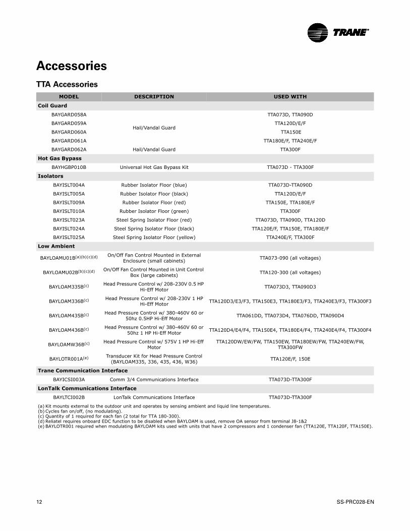
TTA Accessories
MODEL DESCRIPTION USED WITH
Coil Guard
BAYGARD058A
Hail/Vandal Guard
TTA073D, TTA090D
BAYGARD059A TTA120D/E/F
BAYGARD060A TTA150E
BAYGARD061A TTA180E/F, TTA240E/F
BAYGARD062A Hail/Vandal Guard TTA300F
Hot Gas Bypass
BAYHGBP010B Universal Hot Gas Bypass Kit TTA073D - TTA300F
Isolators
BAYISLT004A Rubber Isolator Floor (blue) TTA073D-TTA090D
BAYISLT005A Rubber Isolator Floor (black) TTA120D/E/F
BAYISLT009A Rubber Isolator Floor (red) TTA150E, TTA180E/F
BAYISLT010A Rubber Isolator Floor (green) TTA300F
BAYISLT023A Steel Spring Isolator Floor (red) TTA073D, TTA090D, TTA120D
BAYISLT024A Steel Spring Isolator Floor (black) TTA120E/F, TTA150E, TTA180E/F
BAYISLT025A Steel Spring Isolator Floor (yellow) TTA240E/F, TTA300F
Low Ambient
BAYLOAMU01B(a)(b)(c)(d)
(a) Kit mounts external to the outdoor unit and operates by sensing ambient and liquid line temperatures.(b) Cycles fan on/off, (no modulating).(c) Quantity of 1 required for each fan (2 total for TTA 180-300).(d) Reliatel requires onboard EDC function to be disabled when BAYLOAM is used, remove OA sensor from terminal J8-1&2
On/Off Fan Control Mounted in External Enclosure (small cabinets) TTA073-090 (all voltages)
BAYLOAMU02B(b)(c)(d) On/Off Fan Control Mounted in Unit Control Box (large cabinets) TTA120-300 (all voltages)
BAYLOAM335B(c) Head Pressure Control w/ 208-230V 0.5 HP Hi-Eff Motor TTA073D3, TTA090D3
BAYLOAM336B(c) Head Pressure Control w/ 208-230V 1 HP Hi-Eff Motor TTA120D3/E3/F3, TTA150E3, TTA180E3/F3, TTA240E3/F3, TTA300F3
BAYLOAM435B(c) Head Pressure Control w/ 380-460V 60 or 50hz 0.5HP Hi-Eff Motor TTA061DD, TTA073D4, TTA076DD, TTA090D4
BAYLOAM436B(c) Head Pressure Control w/ 380-460V 60 or 50hz 1 HP Hi-Eff Motor TTA120D4/E4/F4, TTA150E4, TTA180E4/F4, TTA240E4/F4, TTA300F4
BAYLOAMW36B(c) Head Pressure Control w/ 575V 1 HP Hi-Eff Motor
TTA120DW/EW/FW, TTA150EW, TTA180EW/FW, TTA240EW/FW, TTA300FW
BAYLOTR001A(e)
(e) BAYLOTR001 required when modulating BAYLOAM kits used with units that have 2 compressors and 1 condenser fan (TTA120E, TTA120F, TTA150E).
Transducer Kit for Head Pressure Control (BAYLOAM335, 336, 435, 436, W36) TTA120E/F, 150E
Trane Communication Interface
BAYICSI003A Comm 3/4 Communications Interface TTA073D-TTA300F
LonTalk Communications Interface
BAYLTCI002B LonTalk Communications Interface TTA073D-TTA300F
12 SS-PRC028-EN
Accessories
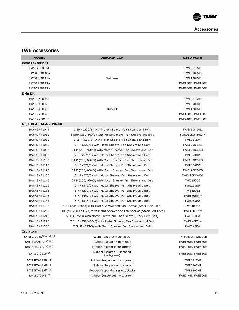
TWE Accessories
MODEL DESCRIPTION USED WITH
Base (Subbase)
BAYBASE009A
Subbase
TWE061D/E
BAYBASE0010A TWE090D/E
BAYBASE0011A TWE120D/E
BAYBASE0012A TWE150E, TWE180E
BAYBASE0013A TWE240E, TWE300E
Drip Kit
BAYDRKT006B
Drip Kit
TWE061D/E
BAYDRKT007B TWE090D/E
BAYDRKT008B TWE120D/E
BAYDRKT009B TWE150E, TWE180E
BAYDRKT010B TWE240E, TWE300E
High Static Motor Kits(a)
BAYHSMT104B 1.5HP (230/1) with Motor Sheave, Fan Sheave and Belt TWE061D1/E1
BAYHSMT105B 1.5HP (230-460/3) with Motor Sheave, Fan Sheave and Belt TWE061D3-4/E3-4
BAYHSMT106B 1.5HP (575/3) with Motor Sheave, Fan Sheave and Belt TWE061DW
BAYHSMT107B 2 HP (230/1) with Motor Sheave, Fan Sheave and Belt TWE090D1/E1
BAYHSMT108B 2 HP (230/460/3) with Motor Sheave, Fan Sheave and Belt TWE090D3/E3
BAYHSMT109B 2 HP (575/3) with Motor Sheave, Fan Sheave and Belt TWE090DW
BAYHSMT110B 3 HP (230/460/3) with Motor Sheave, Fan Sheave and Belt TWE090D3/E3
BAYHSMT111B 3 HP (575/3) with Motor Sheave, Fan Sheave and Belt TWE090DW
BAYHSMT112B 3 HP (230/460/3) with Motor Sheave, Fan Sheave and Belt TWE120D3/E3
BAYHSMT113B 3 HP (575/3) with Motor Sheave, Fan Sheave and Belt TWE120DW/EW
BAYHSMT114B 3 HP (230/460/3) with Motor Sheave, Fan Sheave and Belt TWE150E3
BAYHSMT115B 3 HP (575/3) with Motor Sheave, Fan Sheave and Belt TWE150EW
BAYHSMT116B 5 HP (230/3) with Motor Sheave, Fan Sheave and Belt TWE150E3
BAYHSMT117B 5 HP (460/3) with Motor Sheave, Fan Sheave and Belt TWE150E3(b)
BAYHSMT118B 5 HP (575/3) with Motor Sheave, Fan Sheave and Belt TWE150EW
BAYHSMT119B 5 HP (208-230/3) with Motor Sheave and Fan Sheave (Stock Belt used) TWE180E3
BAYHSMT120B 5 HP (460/380-415/3) with Motor Sheave and Fan Sheave (Stock Belt used) TWE180E3(b)
BAYHSMT121B 5 HP (575/3) with Motor Sheave and Fan Sheave (Stock Belt used) TWE180EW
BAYHSMT122B 7.5 HP (230/460/3) with Motor Sheave, Fan Sheave and Belt TWE240E3-4
BAYHSMT123B 7.5 HP (575/3) with Motor Sheave, Fan Sheave and Belt TWE240EW
Isolators
BAYISLT004A(b)(c)(d)(e) Rubber Isolator Floor (blue) TWE061D-TWE120E
BAYISLT009A(b)(c)(d) Rubber Isolator Floor (red) TWE150E, TWE180E
BAYISLT010A(b)(c)(d) Rubber Isolator Floor (green) TWE240E, TWE300E
BAYISLT012B(d) Rubber Isolator Suspended (red/green) TWE150E, TWE180E
BAYISLT013B(d)(e) Rubber Suspended (red/green) TWE061D/E
BAYISLT014A(d)(e) Rubber Suspended (green) TWE090D/E
BAYISLT015B(d)(e) Rubber Suspended (green/black) TWE120D/E
BAYISLT016B(d) Rubber Suspended (red/green) TWE240E, TWE300E
SS-PRC028-EN 13
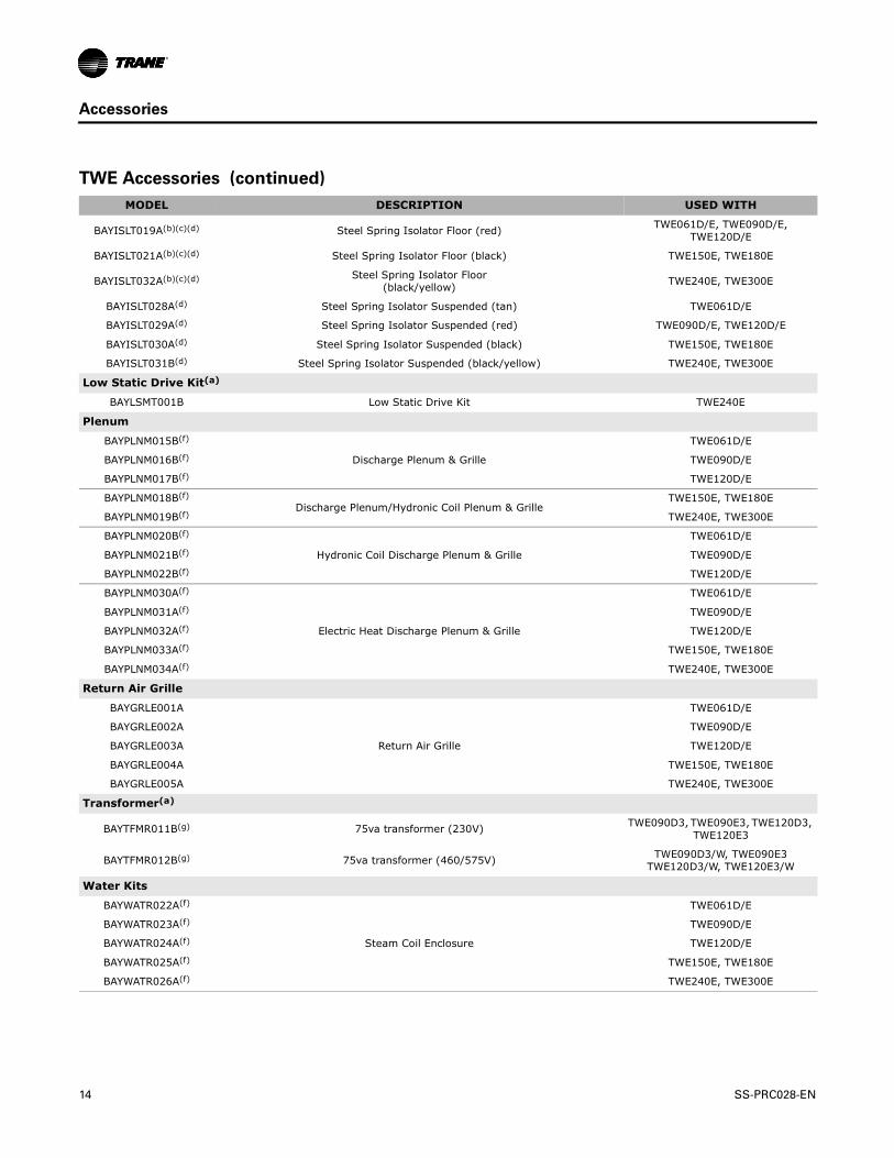
Accessories
BAYISLT019A(b)(c)(d) Steel Spring Isolator Floor (red) TWE061D/E, TWE090D/E, TWE120D/E
BAYISLT021A(b)(c)(d) Steel Spring Isolator Floor (black) TWE150E, TWE180E
BAYISLT032A(b)(c)(d) Steel Spring Isolator Floor (black/yellow) TWE240E, TWE300E
BAYISLT028A(d) Steel Spring Isolator Suspended (tan) TWE061D/E
BAYISLT029A(d) Steel Spring Isolator Suspended (red) TWE090D/E, TWE120D/E
BAYISLT030A(d) Steel Spring Isolator Suspended (black) TWE150E, TWE180E
BAYISLT031B(d) Steel Spring Isolator Suspended (black/yellow) TWE240E, TWE300E
Low Static Drive Kit(a)
BAYLSMT001B Low Static Drive Kit TWE240E
Plenum
BAYPLNM015B(f)
Discharge Plenum & Grille
TWE061D/E
BAYPLNM016B(f) TWE090D/E
BAYPLNM017B(f) TWE120D/E
BAYPLNM018B(f)Discharge Plenum/Hydronic Coil Plenum & Grille
TWE150E, TWE180E
BAYPLNM019B(f) TWE240E, TWE300E
BAYPLNM020B(f)
Hydronic Coil Discharge Plenum & Grille
TWE061D/E
BAYPLNM021B(f) TWE090D/E
BAYPLNM022B(f) TWE120D/E
BAYPLNM030A(f)
Electric Heat Discharge Plenum & Grille
TWE061D/E
BAYPLNM031A(f) TWE090D/E
BAYPLNM032A(f) TWE120D/E
BAYPLNM033A(f) TWE150E, TWE180E
BAYPLNM034A(f) TWE240E, TWE300E
Return Air Grille
BAYGRLE001A
Return Air Grille
TWE061D/E
BAYGRLE002A TWE090D/E
BAYGRLE003A TWE120D/E
BAYGRLE004A TWE150E, TWE180E
BAYGRLE005A TWE240E, TWE300E
Transformer(a)
BAYTFMR011B(g) 75va transformer (230V) TWE090D3, TWE090E3, TWE120D3, TWE120E3
BAYTFMR012B(g) 75va transformer (460/575V) TWE090D3/W, TWE090E3 TWE120D3/W, TWE120E3/W
Water Kits
BAYWATR022A(f)
Steam Coil Enclosure
TWE061D/E
BAYWATR023A(f) TWE090D/E
BAYWATR024A(f) TWE120D/E
BAYWATR025A(f) TWE150E, TWE180E
BAYWATR026A(f) TWE240E, TWE300E
TWE Accessories (continued)
MODEL DESCRIPTION USED WITH
14 SS-PRC028-EN

Accessories
BAYWATR027A(f)
Hot Water Coil Enclosure
TWE061D/E
BAYWATR028A(f) TWE090D/E
BAYWATR029A(f) TWE120D/E
BAYWATR030A(f) TWE150E, TWE180E
BAYWATR031A(f) TWE240E, TWE300E
Wire Kit(a)
BAYWRKT002B(h) 180° Blower Discharge Reversal Kit TWE061D-TWE120E
(a) Used on standard air handlers only.(b) When the air handler is in the vertical position and close proximity trapping of condensate is required, use of subbase is required.(c) Requires use of subbase accessory.(d) In units with steam or hot water coils applied vertically or horizontally, check IOM for proper Isolator Kit selection.(e) Do not use if blower will operate less than 600 RPM.(f) When installed horizontally, plenum/water coil must be self-supported.(g) Required when 6 -10 ton air handlers are matched with 3-6 ton condensing units.(h)Cannot be used on TWE150-300, due to motor mount location.
TWE Accessories (continued)
MODEL DESCRIPTION USED WITH
SS-PRC028-EN 15

Accessories
Electric Heaters
MODEL DESCRIPTION USED WITH
6-10 Ton Electric Heater Selection
BAYHTRL106A 4.33/5.76 KW Heater 208/240/1 Phase TWE061D1-TWE120E1
BAYHTRL112A 8.65/11.52 KW Heater 208/240/1 Phase TWE061D1-TWE120E1
BAYHTRL117A 12.98/17.28 KW Heater 208/240/1 Phase TWE061D1-TWE120E1
BAYHTRL123A 17.31/23.04 KW Heater 208/240/1 Phase TWE061D1-TWE120E1
BAYHTRL129A 21.63/28.80 KW Heater 208/240/1 Phase TWE061D1-TWE120E1
BAYHTRL305A 3.76/5.00 KW Heater 208/240/3 Phase TWE061D3-TWE120E3
BAYHTRL310A 7.48/9.96 KW Heater 208/240/3 Phase TWE061D3-TWE120E3
BAYHTRL315A 11.24/14.96 KW Heater 208/240/3 Phase TWE061D3-TWE120E3
BAYHTRL325A 18.72/24.92KW Heater 208/240/3 Phase TWE061D3-TWE120E3
BAYHTRL335A 26.20/34.88 KW Heater 208/240/3 Phase TWE061D3-TWE120E3
BAYHTRL405A 5.00 KW Heater 460/3 Phase TWE061D4-TWE120E4
BAYHTRL410A 9.96 KW Heater 460/3 Phase TWE061D4-TWE120E4
BAYHTRL415A 14.96 KW Heater 460/3 Phase TWE061D4-TWE120E4
BAYHTRL425A 24.92 KW Heater 460/3 Phase TWE061D4-TWE120E4
BAYHTRL435A 34.88 KW Heater 460/3 Phase TWE061D4-TWE120E4
BAYHTRLW05A 5 KW Heater 575/3 Phase TWE061DW-TWE120EW
BAYHTRLW10A 9.96 KW Heater 575/3 Phase TWE061DW-TWE120EW
BAYHTRLW15A 14.96 KW Heater 575/3 Phase TWE061DW-TWE120EW
BAYHTRLW25A 24.92 KW Heater 575/3 Phase TWE061DW-TWE120EW
BAYHTRLW35A 34.88 KW Heater 575/3 Phase TWE061DW-TWE120EW
12½ - 25 Ton Electric Heater Selection
BAYHTRM310A 7.51/10.0 KW Heater 208/230 3 Phase TWE150E3-TWE300E3
BAYHTRM320A 14.96/19.92 KW Heater 208/230 3 Phase TWE150E3-TWE2300E3
BAYHTRM330A 22.47/29.92 KW Heater 208/230 3 Phase TWE150E3-TWE300E3
BAYHTRM350A 37.44/49.84 KW Heater 208/230 3 Phase TWE150E3-TWE300E3
BAYHTRM410A 10.0 KW Heater 460/3 Phase TWE150E4-TWE300E4
BAYHTRM420A 19.92 KW Heater 460/3 Phase TWE150E4-TWE300E4
BAYHTRM430A 29.92 KW Heater 460/3 Phase TWE150E4-TWE300E4
BAYHTRM450A 49.84 KW Heater 460/3 Phase TWE150E4-TWE300E4
BAYHTRMW10A 10.0 KW Heater 575/3 Phase TWE150EW-TWE300EW
BAYHTRMW20A 19.92 KW Heater 575/3 Phase TWE150EW-TWE300EW
BAYHTRMW30A 29.92 KW Heater 575/3 Phase TWE150EW-TWE300EW
BAYHTRMW50A 49.84 KW Heater 575/3 Phase TWE150EW-TWE300EW
16 SS-PRC028-EN

Application Considerations
Application of this product should be within the cataloged airflow and performance considerations.
Clearance Requirements
The recommended clearances identified with unit dimensions should be maintained to assure adequate serviceability, maximum capacity and peak operating efficiency. Actual clearances which appear inadequate should be reviewed with the local Trane Representative.
180° Blower Rotation
The 5, 7½, and 10 ton air handler blower section can be rotated 180° to change the discharge pattern. This modification must be done in the field and requires an additional kit. See unit installer's guide.
Note: 2-speed VFD and SZVAV air handlers cannot be rotated.
Low Ambient Cooling
As manufactured, electromechanical units can operate to 50° F in the cooling mode of operation. An accessory head pressure control will allow operation to 0° F outdoor ambient. When using these units with control systems such as bypass changeover Variable Air Volume, make sure to consider the requirement for a head pressure control to allow low ambient cooling.
Figure 1. Typical Split System Application
Split Condensing
Unit
Air HandlingUnit
SS-PRC028-EN 17

Application Considerations
Figure 2. Typical Horizontal Air Handler Application
Figure 3. Typical Vertical Air Handler Application
Electric HeaterAssembly
Air Handler
Heating Coil & Enclosure Assembly
(Steam or Hot Water)
Isolator (4X)(Spring or Rubber)
Support Rods and AttachingHardware (by others)
Discharge Plenum &Grille Assembly
Heating Coil &Enclosure Assembly
Air Handler
Return-Air Grille
Subbase
Isolators(Spring or Rubber)
HorizontalDrain
VerticalDrain
18 SS-PRC028-EN

SS-PRC028-EN 19
Selection Procedure
Cooling Capacity
1. Calculate the building’s total and sensible cooling loads at design conditions. Use the Trane calculation form or any other standard accepted method.
2. Size the equipment using Table 7, p. 27 to Table 17, p. 37. Match the cooling loads at design conditions.
Example: The following are the building cooling requirements:
a. Electrical Characteristics: 460/60/3
b. Summer Design Conditions: Entering Evaporator Coil: 80°F DB/67°F WB, Outdoor Ambient: 95°F
c. Total Cooling Load: 86 MBh
d. Sensible Cooling Load: 60 MBh
e. Airflow: 3000 cfm External Static Pressure: 0.77 inches of water gauge
Table 7, p. 27 shows that TTA090D with TWE090D has a gross cooling capacity of 94.8 MBh and 72.7 MBh sensible capacity at 95°F DB ambient and 3000 cfm with 80°F DB/67° F WB air entering the evaporator.
To find the net cooling capacities, fan motor heat must be subtracted. Determine the total unit static pressure:
External Static: 0.77 in. Standard Filter: 0.10 in. Supplementary Electric Heat: 0.23 in. Total Static Pressure 1.10 in.
Note: The Evaporator Fan Performance Table has included the effect of a 1 in. filter already. Therefore, the actual Total Static Pressure is 1.10 - 0.10 = 1.00 in. With 3000 cfm and 1.00 inches, Table 39, p. 59 shows 1.97 Bhp (high static drive kit required).
Note: The formula below the table can be used to calculate Fan Motor Heat: 3.15 X Bhp = MBh 3.15 X 1.97 = 6.2 MBh Net Total Cooling Capacity = 94.8 MBh - 6.2 = 88.6 MBh Net Sensible Cooling Capacity = 72.7 MBh - 6.2 = 66.5 MBh
Heating Capacity
1. Calculate the building heating load using the Trane calculation form or any other standard accepted method.
2. Size the system heating capacity to match the calculated building heating load. The following are building heating requirements:
a. Total Heating Load: 97.0 MBh
b. 3000 cfm
c. Electric Supplementary Heaters
From Table 57, p. 77, the 34.88 kW heater has a capacity of 119,045 Btuh. From Table 67, p. 95, the 34.88 kW at 460v indicates the heater model number is BAYHTRL435A. This heater will adequately cover the building’s heating requirement.
Air Delivery Selection
External static pressure drop through the air distribution system has been calculated to be 0.77 inches of water gauge. From Table 56, p. 76 static pressure drop through the electric heater is 0.23 inches of water (0.77 + 0.23 = 1.00 in.). Enter Table 39, p. 59 for TWE090D at 3000 cfm and 1.00 static pressure. The high static motor at 1020 RPM will give the desired airflow.

Model Number Descriptions
T T A 2 4 0 F 3 0 0 * *1 2 3 4 5 6 7 8 9 10 11 12
All products are identified by a multiple-character model number that precisely identifies a particular type of unit. An explanation of the alphanumeric identification code is provided. Its use will enable the owner/operator, installing contractors, and service engineers to define the operation, specific components, and other options for any specific unit.
Note: When ordering replacement parts or requesting service, be sure to refer to the specific model number, serial number, and DL number (if applicable) stamped on the unit nameplate.
DIGITS 1 - 3: Product TypeTTA = Split System Cooling
DIGITS 4 - 6: Nominal Gross Cooling Capacity (MBh)073 = 6 Tons090 = 7½ Tons120 = 10 Tons150 = 12½ Tons180 = 15 Tons240 = 20 Tons300 = 25 Tons
DIGIT 7: Major Development SequenceD = Single CircuitE = Dual CircuitF = Manifold Scroll Compressors
DIGIT 8: Electrical Characteristics3 = 208-230/60/34 = 460/60/3W = 575/60/3K = 380/60/3
20
DIGITS 9 - 10: Factory Installed Options00 = Packed Stock0S = Black Epoxy Coated Coil0R = ReliaTel, no LCI Board0T = ReliaTel, no LCI Board with Black
Epoxy Coated Coil0U = ReliaTel, with LCI Board0W = ReliaTel, with LCI Board and Black
Epoxy Coated CoilH0 = Hail Guard with Packed StockHS = Hail Guard with Black Epoxy
Coated CoilHR = Hail Guard with ReliaTel,
no LCI BoardHT = Hail Guard with ReliaTel,
no LCI Board with Black Epoxy Coated Coil
HU = Hail Guard with ReliaTel, with LCI Board
HW= Hail Guard with ReliaTel, with LCI Board and Black Epoxy Coated Coil
DIGITS 11: Minor Design Sequence* = Current Design Sequence1
DIGITS 12: Service Digit* = Current Design Sequence1
1 * = sequential alpha character
SS-PRC028-EN

Model Number Descriptions
T W E 2 4 0 E 3 0 0 *
1 2 3 4 5 6 7 8 9 10 11 12
All products are identified by a multiple-character model number that precisely identifies a particular type of unit. An explanation of the alphanumeric identification code is provided. Its use will enable the owner/operator, installing contractors, and service engineers to define the operation, specific components, and other options for any specific unit.
Note: When ordering replacement parts or requesting service, be sure to refer to the specific model number, serial number, and DL number (if applicable) stamped on the unit nameplate.
DIGITS 1 - 3: Product TypeTWE = Split System Heat Pump/Cooling Air Handler
DIGITS 4 - 6: Nominal Gross Cooling Capacity (MBh)061 = 5Tons090 = 7½ Tons120 = 10 Tons150 = 12½ Tons180 = 15 Tons240 = 20 Tons300 = 25 Tons
DIGIT 7: Major Development SequenceD = Single CircuitE = Dual Circuit
DIGIT 8: Electrical Characteristics1 = 208-230/60/13 = 208-230/60/34 = 460/60/3W = 575/60/3K = 380/60/3
SS-PRC028-EN
DIGITS 9 - 10: Factory Installed Options00 = Packed Stock (Standard)03 = 2-Speed Variable Frequency Drive
(VFD) Standard Motor Electromechanical Condenser only
04 = 2-Speed Variable Frequency Drive (VFD) Oversized Motor Electromechanical Condenser only
R3 = Single Zone Variable Air Volume (VFD) Standard Motor - Reliatel Cond only
R4 = Single Zone Variable Air Volume (VFD) Oversized Motor - Reliatel Cond only
DIGITS 11: Minor Design Sequence* = Current Design Sequence1
DIGITS 12: Service Digit* = Current Design Sequence1
1 * = sequential alpha character
21

General Data
Gen
era
l D
ata
Tab
le 1
.G
en
era
l D
ata
— 6
-12½
To
n C
on
den
sin
g U
nit
s —
60
Hz
6 T
on
s7
½ T
on
s1
0 T
on
s1
2½
Ton
s
Sin
gle
Co
mp
ress
or
TTA
07
3D
3,
D4
,D
K,
DW
Sin
gle
Co
mp
ress
or
TTA
09
0D
3, D
4,
DK
, D
W
Sin
gle
Co
mp
ress
or
TTA
12
0D
3,
D4
, D
K,
DW
Du
al
Co
mp
ress
or
TTA
12
0E3
, E4
, E
K,
EW
Man
ifo
lded
C
om
pre
sso
r TT
A1
20
F3,
F4,
FW
Du
alC
omp
ress
or
TTA
15
0E3
, E4
, EK
, E
WC
ooli
ng
Per
form
ance
Gro
ss C
ooli
ng
Cap
acit
yM
atch
ed A
ir H
andl
er77
,000
94,0
0012
4,00
012
2,00
012
3,00
015
4,00
0C
onde
nsin
g U
nit
Onl
y74
,000
90,0
0011
2,00
011
0,00
011
4,00
014
4,00
0AR
I N
et C
oolin
g C
apac
ity75
,000
92,0
0012
0,00
011
9,00
012
0,00
015
0,00
0E
ffic
ien
cyM
atch
ed A
ir H
andl
er (
EER
)11
.211
.211
.211
.211
.211
.0Con
dens
ing
Uni
t O
nly
(EER
)12
.512
.412
.212
.212
.211
.7Sy
stem
Int
egra
ted
Part
Loa
d Va
lue
(IPL
V)
N/A
N/A
N/A
12.0
14.5
13.4
Syst
em (
IEER
)13
.012
.212
.211
.714
.513
.2C
onde
nsin
g U
nit
Onl
y (I
PLV)
N/A
N/A
N/A
15.9
17.2
15.9
Syst
em k
W/C
onde
nsin
g U
nit
kW6.
70/5
.92
8.22
/7.2
610
.72/
9.18
10.6
2/9.
0110
.72/
9.35
13.6
3/12
.31
Com
pre
sso
rTy
peScr
oll
Scr
oll
Scr
oll
Scr
oll
Man
ifold
ed S
crol
lsScr
oll
No.
/Ton
s1/
5.6
1/6.
91/
8.6
2/4.
22/
4.3
2/5.
6S
yste
m D
ata
No.
Ref
rige
rant
Cir
cuits
11
12
12
Suc
tion
Line
(in
.) O
D1
1/8
1 3/
81
3/8
1 1/
81
3/8
1 1/
8Li
quid
Lin
e (i
n.)
OD
1/2
5/8
1/2
1/2
1/2
1/2
Ou
tdo
or
Co
il -
Typ
eLa
nced
Lanc
edLa
nced
Lanc
edLa
nced
Lanc
edTu
be S
ize
(in.
) O
D0.
375
0.37
50.
375
0.37
50.
375
0.37
5Fa
ce A
rea
(sq
ft)
19.2
19.2
24.0
24.0
24.0
30.6
Row
s/FP
I2/
182/
182/
182/
182/
182/
18O
utd
oo
r Fa
n -
Typ
ePr
opel
ler
Prop
elle
rPr
opel
ler
Prop
elle
rPr
opel
ler
Prop
elle
rN
o. U
sed/
Dia
met
er (
in.)
1/26
1/26
1/28
1/28
1/28
1/28
Dri
ve T
ype/
No.
Spe
eds
Dir
ect/
1D
irec
t/1
Dir
ect/
1D
irec
t/1
Direc
t/1
Dir
ect/
1C
FM65
3065
3096
0096
0096
0098
00N
o. M
otor
/HP
1/0.
51/
0.5
1/1
1/1
1/1
1/1
Mot
or R
PM11
0011
0011
0011
0011
0011
00R
efri
ger
ant
Ch
arg
e
(Fie
ld S
up
pli
ed)
(lbs
of
R41
0A)
15.7
17.6
22.5
24.8
21.2
30.7
Sh
ipp
ing
Dim
ensi
on
s (H
xWxD
)43
.54”
x 4
3” x
36.
5”43
.54”
x 4
3” x
36.
5”43
.49”
x 5
3” x
40.
5”49
.48”
x 5
3.25
” x
41”
22 SS-PRC028-EN

General Data
Table 2
.G
en
era
l D
ata
— 1
5 -
25
To
n C
on
den
sin
g U
nit
s —
60
Hz
15
To
ns
20
To
ns
25
To
nD
ual
C
om
pre
sso
r T
TA
18
0E
3,
E4
, E
K,
EW
Man
ifo
lded
C
om
pre
ssor
T
TA1
80
F3,
F4,
FK,
FW
Du
al
Co
mp
ress
or
TTA
24
0E3
, E4
, EK
, E
W
Man
ifo
lded
C
om
pre
sso
r TT
A2
40
F3,
F4,
FK,
FW
Man
ifo
lded
C
om
pre
sso
r TT
A3
00
F3,
F4,
FK,
FWC
ooli
ng
Per
form
ance
Gro
ss C
ooli
ng
Cap
acit
yM
atch
ed A
ir H
andl
er18
5,00
018
6,00
026
3,00
025
4,00
030
7,00
0C
onde
nsin
g U
nit
Onl
y17
8,00
018
2,00
027
0,00
026
6,00
030
4,00
0AR
I N
et C
oolin
g C
apac
ity18
0,00
018
0,00
025
4,00
024
6,00
029
2,00
0E
ffic
ien
cyM
atch
ed A
ir H
andl
er (
EER
)11
.011
.010
.010
.010
.0C
onde
nsin
g U
nit
Onl
y (E
ER)
12.6
12.8
12.1
12.0
12.4
Syst
em I
nteg
rate
d Pa
rt L
oad
Valu
e (I
PLV)
13.2
13.4
11.2
12.0
Syst
em (
IEER
)12
.912
.510
.911
.911
.0C
onde
nsin
g U
nit
Onl
y (I
PLV)
17.3
15.9
15.9
16.0
Syst
em k
W/
Con
dens
ing
Uni
t (k
W)
16.3
6/14
.13
16.3
7/14
.22
25.4
0/22
.32
24.6
/22.
1729
.19/
24.4
9
Com
pre
sso
rTy
peScr
oll
Man
ifold
ed S
crol
lsScr
oll
Man
ifold
ed S
crol
lM
anifo
lded
Scr
oll
No.
/Ton
s2/
6.9
2/6.
92/
10.1
2/10
.12/
11.4
Sys
tem
Dat
aN
o. R
efri
gera
nt C
ircu
its2
12
11
Suc
tion
Line
(in
.) O
D1
3/8
1 5/
81
3/8
1 5/
82
1/8
Liqu
id L
ine
(in.
) O
D1/
25/
81/
25/
85/
8O
utd
oo
r C
oil
- T
ype
Lanc
edLa
nced
Lanc
edLa
nced
Lanc
edTu
be S
ize
(in.
) O
D0.
375
0.37
50.
375
0.37
50.
375
Face
Are
a (s
q ft
)52
.652
.652
.652
.657
.05
Row
s/FP
I2/
182/
182/
182/
183/
18O
utd
oo
r Fa
n -
Typ
ePr
opel
ler
Prop
elle
rPr
opel
ler
Prop
elle
rPr
opel
ler
No.
Use
d/D
iam
eter
(in
.)2/
282/
282/
282/
282/
28D
rive
Typ
e/N
o. S
peed
sD
irec
t/1
Direc
t/1
Dir
ect/
1D
irec
t/1
Dir
ect/
1C
FM19
500
1950
019
500
1950
019
500
No.
Mot
or/H
P2/
12/
12/
12/
12/
1M
otor
RPM
1100
1100
1100
1100
1100
Ref
rig
eran
t C
har
ge
(F
ield
Su
pp
lied
) (l
bs o
f R
410A
)39
37.6
43.8
41.3
62.5
Sh
ipp
ing
Dim
ensi
on
s (H
xWxD
)49
.48”
x 9
4.75
” x
47”
49.4
8” x
94.
75”
x 47
”55
.48"
x 9
4.75
" x
47"
SS-PRC028-EN 23
General Data
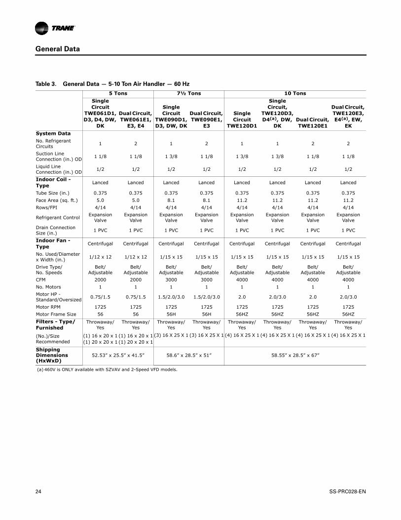
Table 3. General Data — 5-10 Ton Air Handler — 60 Hz
5 Tons 7½ Tons 10 TonsSingle Circuit
TWE061D1, D3, D4, DW,
DK
Dual Circuit, TWE061E1,
E3, E4
Single Circuit
TWE090D1, D3, DW, DK
Dual Circuit, TWE090E1,
E3
Single Circuit
TWE120D1
Single Circuit,
TWE120D3, D4(a), DW,
DKDual Circuit, TWE120E1
Dual Circuit, TWE120E3, E4(a), EW,
EKSystem DataNo. Refrigerant Circuits 1 2 1 2 1 1 2 2
Suction Line Connection (in.) OD 1 1/8 1 1/8 1 3/8 1 1/8 1 3/8 1 3/8 1 1/8 1 1/8
Liquid Line Connection (in.) OD 1/2 1/2 1/2 1/2 1/2 1/2 1/2 1/2
Indoor Coil - Type Lanced Lanced Lanced Lanced Lanced Lanced Lanced Lanced
Tube Size (in.) 0.375 0.375 0.375 0.375 0.375 0.375 0.375 0.375Face Area (sq. ft.) 5.0 5.0 8.1 8.1 11.2 11.2 11.2 11.2Rows/FPI 4/14 4/14 4/14 4/14 4/14 4/14 4/14 4/14
Refrigerant Control Expansion Valve
Expansion Valve
Expansion Valve
Expansion Valve
Expansion Valve
Expansion Valve
Expansion Valve
Expansion Valve
Drain Connection Size (in.) 1 PVC 1 PVC 1 PVC 1 PVC 1 PVC 1 PVC 1 PVC 1 PVC
Indoor Fan - Type Centrifugal Centrifugal Centrifugal Centrifugal Centrifugal Centrifugal Centrifugal Centrifugal
No. Used/Diameter x Width (in.) 1/12 x 12 1/12 x 12 1/15 x 15 1/15 x 15 1/15 x 15 1/15 x 15 1/15 x 15 1/15 x 15
Drive Type/ No. Speeds
Belt/Adjustable
Belt/Adjustable
Belt/Adjustable
Belt/Adjustable
Belt/Adjustable
Belt/Adjustable
Belt/Adjustable
Belt/Adjustable
CFM 2000 2000 3000 3000 4000 4000 4000 4000No. Motors 1 1 1 1 1 1 1 1Motor HP - Standard/Oversized 0.75/1.5 0.75/1.5 1.5/2.0/3.0 1.5/2.0/3.0 2.0 2.0/3.0 2.0 2.0/3.0
Motor RPM 1725 1725 1725 1725 1725 1725 1725 1725Motor Frame Size 56 56 56H 56H 56HZ 56HZ 56HZ 56HZFilters - Type/Furnished
Throwaway/Yes
Throwaway/Yes
Throwaway/Yes
Throwaway/Yes
Throwaway/Yes
Throwaway/Yes
Throwaway/Yes
Throwaway/Yes
(No.)/Size Recommended
(1) 16 x 20 x 1(1) 20 x 20 x 1
(1) 16 x 20 x 1(1) 20 x 20 x 1
(3) 16 X 25 X 1 (3) 16 X 25 X 1 (4) 16 X 25 X 1 (4) 16 X 25 X 1 (4) 16 X 25 X 1 (4) 16 X 25 X 1
Shipping Dimensions (HxWxD)
52.53” x 25.5” x 41.5” 58.6” x 28.5” x 51” 58.55” x 28.5” x 67”
(a) 460V is ONLY available with SZVAV and 2-Speed VFD models.
24 SS-PRC028-EN
General Data
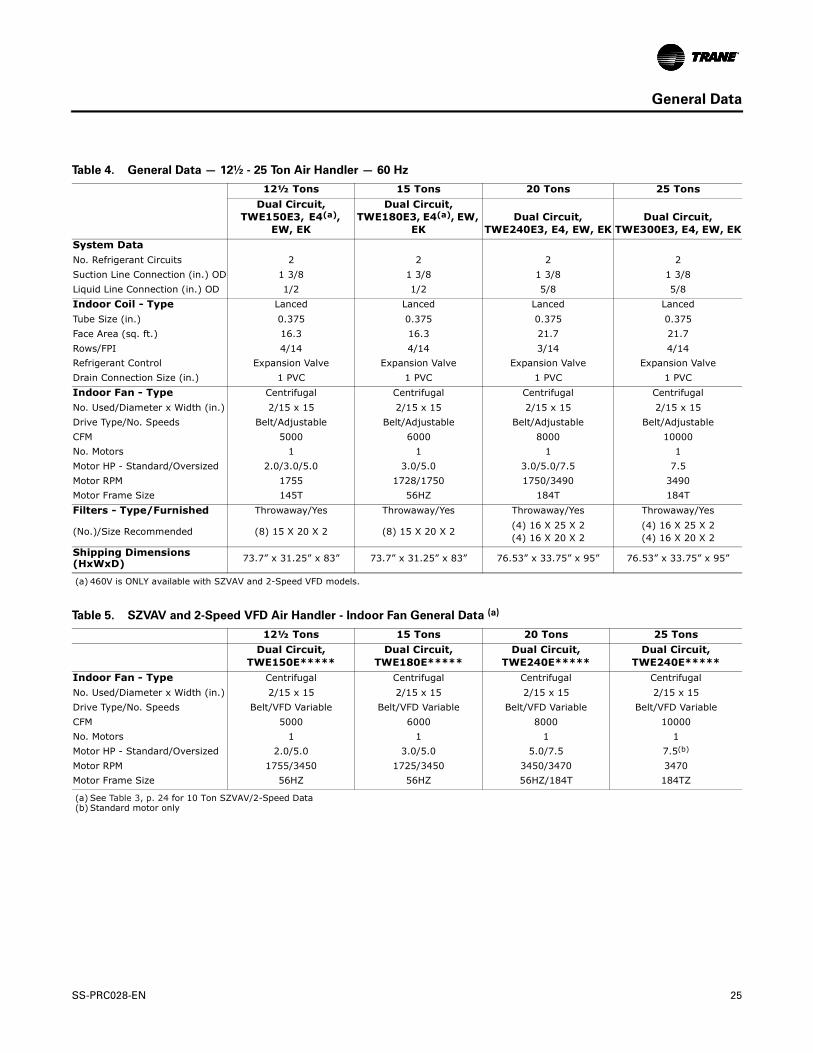
Table 4. General Data — 12½ - 25 Ton Air Handler — 60 Hz
12½ Tons 15 Tons 20 Tons 25 TonsDual Circuit,
TWE150E3, E4(a), EW, EK
Dual Circuit, TWE180E3, E4(a), EW,
EKDual Circuit,
TWE240E3, E4, EW, EKDual Circuit,
TWE300E3, E4, EW, EKSystem DataNo. Refrigerant Circuits 2 2 2 2Suction Line Connection (in.) OD 1 3/8 1 3/8 1 3/8 1 3/8Liquid Line Connection (in.) OD 1/2 1/2 5/8 5/8Indoor Coil - Type Lanced Lanced Lanced LancedTube Size (in.) 0.375 0.375 0.375 0.375Face Area (sq. ft.) 16.3 16.3 21.7 21.7Rows/FPI 4/14 4/14 3/14 4/14Refrigerant Control Expansion Valve Expansion Valve Expansion Valve Expansion ValveDrain Connection Size (in.) 1 PVC 1 PVC 1 PVC 1 PVCIndoor Fan - Type Centrifugal Centrifugal Centrifugal CentrifugalNo. Used/Diameter x Width (in.) 2/15 x 15 2/15 x 15 2/15 x 15 2/15 x 15Drive Type/No. Speeds Belt/Adjustable Belt/Adjustable Belt/Adjustable Belt/AdjustableCFM 5000 6000 8000 10000No. Motors 1 1 1 1Motor HP - Standard/Oversized 2.0/3.0/5.0 3.0/5.0 3.0/5.0/7.5 7.5Motor RPM 1755 1728/1750 1750/3490 3490Motor Frame Size 145T 56HZ 184T 184TFilters - Type/Furnished Throwaway/Yes Throwaway/Yes Throwaway/Yes Throwaway/Yes
(No.)/Size Recommended (8) 15 X 20 X 2 (8) 15 X 20 X 2 (4) 16 X 25 X 2(4) 16 X 20 X 2
(4) 16 X 25 X 2(4) 16 X 20 X 2
Shipping Dimensions (HxWxD) 73.7” x 31.25” x 83” 73.7” x 31.25” x 83” 76.53” x 33.75” x 95” 76.53” x 33.75” x 95”
(a) 460V is ONLY available with SZVAV and 2-Speed VFD models.
Table 5. SZVAV and 2-Speed VFD Air Handler - Indoor Fan General Data (a)
12½ Tons 15 Tons 20 Tons 25 TonsDual Circuit,
TWE150E*****Dual Circuit,
TWE180E*****Dual Circuit,
TWE240E*****Dual Circuit,
TWE240E*****Indoor Fan - Type Centrifugal Centrifugal Centrifugal CentrifugalNo. Used/Diameter x Width (in.) 2/15 x 15 2/15 x 15 2/15 x 15 2/15 x 15Drive Type/No. Speeds Belt/VFD Variable Belt/VFD Variable Belt/VFD Variable Belt/VFD VariableCFM 5000 6000 8000 10000No. Motors 1 1 1 1Motor HP - Standard/Oversized 2.0/5.0 3.0/5.0 5.0/7.5 7.5(b)
Motor RPM 1755/3450 1725/3450 3450/3470 3470Motor Frame Size 56HZ 56HZ 56HZ/184T 184TZ
(a) See Table 3, p. 24 for 10 Ton SZVAV/2-Speed Data(b) Standard motor only
SS-PRC028-EN 25

Performance Data
Table 6. Gross Cooling Capacities (MBH) 6 Tons TTA073D Condensing Unit with 7.5 Tons TWE090D Standard Air Handler (IP)
CFM
EntDB
(°F)
Ambient Temperature (°F)85 95 105
Entering Wet Bulb (°F)61 67 73 61 67 73 61 67 73
MBH SHC MBH SHC MBH SHC MBH SHC MBH SHC MBH SHC MBH SHC MBH SHC MBH SHC
2160
75 72.1 59.9 78.9 46.4 86.3 31.8 68.3 58.1 75.1 44.9 82.2 30.3 64.6 56.3 71.1 43.2 77.8 28.880 72.7 70.7 79.2 56.9 86.7 42.9 69.4 69.1 75.4 55.2 82.5 41.3 66.0 66.0 71.3 53.6 78.1 39.785 75.9 75.9 79.5 67.5 86.9 53.6 72.9 72.9 75.7 65.9 82.8 52.1 69.7 69.7 71.8 64.1 78.4 50.490 79.8 79.8 80.5 78.3 87.1 64.3 76.7 76.7 76.9 76.7 83.0 62.7 73.3 73.3 73.3 73.3 78.6 61.1
2400
75 73.4 63.0 80.1 48.5 87.4 32.3 69.5 61.2 76.3 46.9 83.1 30.8 65.8 59.4 72.1 45.3 78.7 29.380 74.3 74.3 80.4 59.8 87.9 44.4 71.2 71.2 76.5 58.1 83.6 42.9 68.0 68.0 72.4 56.5 79.1 41.385 78.3 78.3 80.9 71.3 88.2 56.2 75.1 75.1 77.1 69.7 83.9 54.7 71.7 71.7 73.0 68.0 79.4 53.090 82.3 82.3 82.3 82.3 88.4 68.0 79.0 79.0 79.0 79.0 84.1 66.1 75.5 75.5 75.5 75.5 79.6 64.4
2640
75 74.6 66.0 81.2 50.6 88.2 32.8 70.6 64.2 77.2 49.0 83.9 31.3 66.8 62.4 73.0 47.3 79.4 29.880 76.2 76.2 81.3 62.3 88.9 46.0 73.0 73.0 77.4 60.7 84.5 44.4 69.6 69.6 73.2 59.0 80.0 42.885 80.4 80.4 82.1 75.0 89.2 58.8 77.0 77.0 78.2 73.4 84.9 57.2 73.5 73.5 74.2 71.7 80.3 55.690 84.5 84.5 84.4 84.4 89.5 71.1 81.0 81.0 81.0 81.0 85.1 69.5 77.4 77.4 77.3 77.3 80.6 67.8
2880
75 75.6 68.9 82.0 52.6 89.0 33.3 71.5 67.1 78.0 51.0 84.6 31.8 67.7 65.3 73.7 49.3 80.0 30.380 77.9 77.9 82.3 64.9 89.7 47.4 74.6 74.6 78.2 63.3 85.3 45.9 71.1 71.1 74.0 61.5 80.7 44.285 82.1 82.1 83.3 78.7 90.1 61.3 78.7 78.7 79.4 77.1 85.7 59.7 75.1 75.1 75.0 75.0 80.9 57.790 86.4 86.4 86.4 86.4 90.5 74.4 82.8 82.8 82.7 82.7 86.1 72.8 79.0 79.0 79.0 79.0 81.5 71.1
Ambient Temperature (°F)115 125
Ent Entering Wet Bulb (°F)DB 61 67 73 61 67 73
CFM (°F) MBH SHC MBH SHC MBH SHC MBH SHC MBH SHC MBH SHC
2160
75 60.7 54.5 66.8 41.5 73.1 27.1 56.5 52.6 62.1 39.6 68.0 25.480 62.6 62.6 67.0 51.8 73.5 38.0 58.9 58.9 62.4 49.9 68.3 36.285 66.2 66.2 67.6 62.4 73.7 48.7 62.3 62.3 63.0 60.4 68.5 46.990 69.7 69.7 69.7 69.7 73.9 59.2 65.7 65.7 65.7 65.7 68.8 57.3
2400
75 61.8 57.6 67.7 43.5 73.9 27.6 57.5 55.6 62.9 41.7 68.7 25.980 64.4 64.4 67.9 54.5 74.4 39.6 60.5 60.5 63.2 52.5 69.1 37.785 68.1 68.1 68.8 66.2 74.6 51.3 64.0 64.0 64.0 64.0 69.3 49.590 71.7 71.7 71.7 71.7 74.9 62.7 67.5 67.5 67.5 67.5 69.7 60.7
2640
75 62.8 60.6 68.5 45.6 74.6 28.1 58.3 58.3 63.6 43.7 69.3 26.480 65.9 65.9 68.8 57.1 75.1 41.1 61.9 61.9 63.9 55.2 69.7 39.285 69.7 69.7 69.7 69.7 75.4 53.9 65.5 65.5 65.5 65.5 69.9 51.790 73.5 73.5 73.4 73.4 75.8 66.0 69.1 69.1 69.0 69.0 70.5 64.1 Notes:
1. All capacities shown are gross and have not considered indoor fan heat. To obtain net cooling, subtract indoor fan heat.
2. MBH = Total Gross Capacity 3. SHC = Sensible Heat Capacity
2880
75 63.7 63.5 69.1 47.6 75.2 28.6 59.5 59.5 64.1 45.7 69.8 26.880 67.3 67.3 69.5 59.7 75.7 42.5 63.2 63.2 64.6 57.7 70.3 40.785 71.1 71.1 71.1 71.1 75.9 55.9 66.8 66.8 66.8 66.8 70.5 54.090 74.9 74.9 75.0 75.0 76.6 69.3 70.4 70.4 70.4 70.4 71.3 67.4
26 SS-PRC028-EN

Performance Data
Table 7. Gross Cooling Capacities (MBH) 7.5 Tons TTA090D Condensing Unit with 7.5 Tons TWE090D Standard Air Handler (IP)
CFM
EntDB
(°F)
Ambient Temperature (°F)85 95 105
Entering Wet Bulb (°F)61 67 73 61 67 73 61 67 73
MBH SHC MBH SHC MBH SHC MBH SHC MBH SHC MBH SHC MBH SHC MBH SHC MBH SHC
2700
75 89.1 74.8 96.9 58.0 105.8 38.9 84.6 72.6 92.5 56.2 101.0 37.2 80.3 70.6 87.8 54.3 95.8 35.580 89.8 88.5 97.1 70.7 105.9 52.8 85.9 85.9 92.7 68.8 101.1 51.0 82.2 82.2 88.0 66.9 96.0 49.285 93.9 93.9 97.5 84.2 106.0 66.3 90.3 90.3 93.2 82.3 101.2 64.6 86.5 86.5 88.6 80.3 96.1 62.790 98.4 98.4 98.9 97.9 106.1 79.8 94.7 94.7 94.7 94.7 101.4 78.1 90.7 90.7 90.7 90.7 96.3 76.2
3000
75 90.6 78.7 98.3 60.6 107.1 39.6 85.9 76.4 93.8 58.8 102.1 37.9 81.6 74.4 88.9 56.9 96.9 36.180 91.8 91.8 98.5 74.2 107.2 54.7 88.2 88.2 94.8 72.7 102.3 52.9 84.4 84.4 89.1 70.4 97.1 51.085 96.5 96.5 99.1 88.9 107.3 69.5 92.8 92.8 95.5 87.4 102.4 67.7 88.8 88.8 90.0 85.0 97.2 65.990 101.2 101.2 101.1 101.1 107.5 84.3 97.3 97.3 97.3 97.3 102.7 82.5 93.2 93.2 93.1 93.1 97.5 80.4
3300
75 91.9 82.3 99.4 63.3 108.1 40.2 87.2 80.1 94.8 61.4 103.1 38.5 82.8 78.1 89.9 59.5 97.8 36.780 94.0 94.0 99.6 77.6 108.3 56.5 90.2 90.2 94.9 75.5 103.3 54.7 86.2 86.2 90.1 73.5 98.0 52.985 98.8 98.8 100.5 93.5 108.5 72.6 94.9 94.9 96.0 91.6 103.5 70.8 90.7 90.7 91.3 89.6 98.1 68.990 103.6 103.6 103.5 103.5 108.7 88.4 99.5 99.5 99.5 99.5 103.8 86.5 95.2 95.2 95.2 95.2 98.6 84.6
3600
75 93.1 85.9 100.4 65.8 109.0 40.9 88.3 83.7 95.7 64.0 103.9 39.2 83.8 81.6 90.7 62.1 98.5 37.480 95.9 95.9 100.6 80.6 109.2 58.3 92.0 92.0 95.9 78.7 104.2 56.5 87.8 87.8 91.0 76.7 98.8 54.685 100.8 100.8 101.8 97.9 109.4 75.6 96.8 96.8 97.3 96.1 104.3 73.8 92.5 92.5 92.4 92.4 98.9 71.990 105.7 105.7 105.6 105.6 109.8 92.5 101.5 101.5 101.5 101.5 104.8 90.6 97.1 97.1 97.1 97.1 99.5 88.6
Ambient Temperature (°F)115 125
Ent Entering Wet Bulb (°F)DB 61 67 73 61 67 73
CFM (°F) MBH SHC MBH SHC MBH SHC MBH SHC MBH SHC MBH SHC
2700
75 75.7 68.5 82.7 52.3 90.2 33.5 70.6 66.1 77.0 50.0 83.9 31.480 78.1 78.1 82.9 64.8 90.4 47.2 73.5 73.5 77.2 62.5 84.1 45.085 82.2 82.2 83.6 78.2 90.5 60.7 77.5 77.5 78.1 75.8 84.3 58.590 86.4 86.4 86.3 86.3 90.8 74.2 81.4 81.4 81.3 81.3 84.6 71.7
3000
75 76.9 72.2 83.7 54.9 91.2 34.2 71.8 69.8 77.9 52.6 84.7 32.080 80.1 80.1 83.9 68.1 91.4 49.0 75.3 75.3 78.1 65.7 85.0 46.885 84.4 84.4 85.0 82.9 91.5 63.8 79.4 79.4 79.3 79.3 85.1 61.690 88.6 88.6 88.5 88.5 91.9 78.3 83.4 83.4 83.4 83.4 85.6 75.9
3300
75 78.1 75.9 84.5 57.5 92.0 34.8 72.7 72.7 78.6 55.2 85.4 32.680 81.8 81.8 84.8 71.3 92.2 50.9 76.9 76.9 79.0 68.9 85.7 48.685 86.2 86.2 86.1 86.1 92.3 66.9 81.0 81.0 81.0 81.0 85.8 64.790 90.5 90.5 90.5 90.5 92.9 82.5 85.1 85.1 85.1 85.1 86.5 80.1 Notes:
1. All capacities shown are gross and have not considered indoor fan heat. To obtain net cooling, subtract indoor fan heat.
2. MBH = Total Gross Capacity 3. SHC = Sensible Heat Capacity
3600
75 78.9 78.9 85.2 60.1 92.6 35.4 74.0 74.0 79.2 57.8 86.0 33.280 83.3 83.3 85.7 74.5 92.9 52.6 78.2 78.2 79.7 72.1 86.3 50.485 87.8 87.8 87.7 87.7 93.0 69.9 82.4 82.4 82.4 82.4 86.4 67.390 92.2 92.2 92.2 92.2 93.8 86.5 86.6 86.6 86.6 86.6 87.4 84.1
SS-PRC028-EN 27

Performance Data
Table 8. Gross Cooling Capacities (MBH) 7.5 Tons TTA090D Condensing Unit with 10 Tons TWE120D Standard Air Handler (IP)
CFM
EntDB
(°F)
Ambient Temperature (°F)85 95 105
Entering Wet Bulb (°F)61 67 73 61 67 73 61 67 73
MBH SHC MBH SHC MBH SHC MBH SHC MBH SHC MBH SHC MBH SHC MBH SHC MBH SHC
3100
75 95.4 84.3 102.9 63.6 111.3 41.4 90.4 81.9 98.2 61.7 106.2 39.6 85.8 79.8 93.2 59.8 100.7 37.880 97.1 97.1 103.1 79.2 111.9 58.1 93.3 93.3 98.4 77.2 106.8 56.3 89.1 89.1 93.5 75.1 101.4 54.485 102.0 102.0 104.0 95.4 112.1 74.5 98.0 98.0 99.4 93.4 107.1 72.7 93.8 93.8 94.6 91.3 101.7 70.890 106.9 106.9 106.8 106.8 112.4 90.1 102.8 102.8 102.7 102.7 107.5 88.2 98.4 98.4 98.3 98.3 102.2 86.2
3400
75 96.7 88.3 104.0 66.3 112.3 42.0 91.6 85.9 99.2 64.4 107.1 40.3 87.0 83.8 94.1 62.4 102.9 38.880 99.3 99.3 104.3 82.8 112.9 60.2 95.3 95.3 100.6 81.3 107.8 58.4 91.0 91.0 94.5 78.7 102.3 56.585 104.4 104.4 105.5 100.5 113.2 78.0 100.2 100.2 100.8 98.5 108.0 75.6 95.8 95.8 95.8 95.8 102.5 73.690 109.3 109.3 109.2 109.2 113.6 94.7 105.1 105.1 105.0 105.0 108.6 92.8 100.5 100.5 100.5 100.5 103.2 90.8
3700
75 97.9 92.3 104.9 68.9 113.1 42.7 92.8 89.9 100.0 67.0 109.1 41.3 88.1 87.7 94.8 65.0 102.2 39.080 101.2 101.2 105.3 86.3 113.8 62.2 97.1 97.1 100.5 84.3 108.6 60.4 92.7 92.7 95.4 82.2 103.1 58.585 106.4 106.4 106.8 105.5 114.0 80.6 102.1 102.1 102.1 102.1 108.8 78.7 97.6 97.6 97.6 97.6 103.3 76.690 111.4 111.4 111.3 111.3 114.7 99.2 107.1 107.1 107.1 107.1 109.7 97.4 102.4 102.4 102.4 102.4 104.2 95.3
4000
75 99.1 96.2 105.7 71.5 115.1 43.7 93.9 93.7 100.8 69.6 108.5 41.5 89.3 89.3 95.4 66.6 102.8 39.780 102.9 102.9 106.3 89.8 114.6 64.2 98.7 98.7 101.4 87.7 109.3 62.4 94.2 94.2 96.2 85.6 103.7 60.585 108.2 108.2 108.1 108.1 114.8 83.7 103.8 103.8 103.8 103.8 109.6 81.8 99.1 99.1 99.1 99.1 104.0 79.790 113.2 113.2 113.2 113.2 115.6 103.7 108.8 108.8 108.8 108.8 110.6 101.8 104.0 104.0 104.0 104.0 105.1 99.7
Ambient Temperature (°F)115 125
Ent Entering Wet Bulb (°F)DB 61 67 73 61 67 73
CFM (°F) MBH SHC MBH SHC MBH SHC MBH SHC MBH SHC MBH SHC
3100
75 81.0 77.4 87.7 57.6 94.8 35.8 75.6 74.9 81.6 55.3 88.1 33.580 84.6 84.6 88.1 72.8 95.5 52.4 79.5 79.5 82.1 70.3 88.9 50.185 89.1 89.1 89.4 89.1 95.7 68.2 83.8 83.8 83.8 83.8 89.1 65.790 93.6 93.6 93.5 93.5 96.3 84.0 88.0 88.0 88.0 88.0 89.8 81.5
3400
75 82.1 81.4 88.5 60.3 95.5 36.4 76.8 76.8 82.3 57.9 88.8 34.280 86.4 86.4 89.0 76.4 96.3 54.4 81.2 81.2 82.9 73.8 89.6 52.285 91.0 91.0 91.0 91.0 96.5 71.3 85.5 85.5 85.5 85.5 89.9 68.890 95.5 95.5 95.5 95.5 97.4 88.5 89.8 89.8 89.8 89.8 90.8 86.0
3700
75 83.3 83.3 89.2 62.9 96.2 37.0 78.1 78.1 82.8 59.4 89.1 37.280 88.0 88.0 89.9 79.9 97.0 56.4 82.5 82.5 83.7 77.3 90.2 54.285 92.6 92.6 92.6 92.6 97.3 74.4 86.9 86.9 86.9 86.9 90.5 71.890 97.2 97.2 97.2 97.2 98.3 93.0 91.3 91.3 91.3 91.3 91.7 90.5 Notes:
1. All capacities shown are gross and have not considered indoor fan heat. To obtain net cooling, subtract indoor fan heat.
2. MBH = Total Gross Capacity 3. SHC = Sensible Heat Capacity
4000
75 84.5 84.5 89.7 64.3 96.7 37.6 79.2 79.2 83.3 61.6 89.6 35.480 89.3 89.3 90.6 83.3 99.0 58.9 83.7 83.7 84.4 80.7 90.6 56.385 94.0 94.0 94.0 94.0 98.0 77.4 88.2 88.2 88.2 88.2 91.1 74.890 98.7 98.7 98.7 98.7 99.2 97.4 92.7 92.7 92.7 92.7 92.6 92.6
28 SS-PRC028-EN

Performance Data
Table 9. Gross Cooling Capacities (MBH) 10 Tons TTA120D Condensing Unit with 10 Tons TWE120D Standard Air Handler (IP)
CFM
EntDB
(°F)
Ambient Temperature (°F)85 95 105
Entering Wet Bulb (°F)61 67 73 61 67 73 61 67 73
MBH SHC MBH SHC MBH SHC MBH SHC MBH SHC MBH SHC MBH SHC MBH SHC MBH SHC
3600
75 116.8 100.6 128.1 77.2 139.8 51.6 111.3 98.0 122.0 74.7 133.2 49.3 105.5 95.4 115.6 72.2 126.2 46.880 118.8 118.8 128.4 95.4 140.2 70.8 114.1 114.1 122.3 92.9 133.6 68.4 109.0 109.0 115.9 90.2 126.6 65.985 125.2 125.2 129.2 114.2 140.5 89.6 120.2 120.2 123.2 111.6 133.8 87.2 115.0 115.0 117.0 109.0 126.8 84.690 131.5 131.5 131.4 131.4 140.9 108.4 126.4 126.4 126.3 126.3 134.2 106.0 120.9 120.9 120.8 120.8 127.2 103.2
4000
75 118.8 106.0 129.9 80.7 141.4 52.5 113.2 103.5 123.6 78.3 134.7 50.1 107.3 100.8 117.1 75.7 127.6 47.780 122.2 122.2 130.2 100.5 141.9 73.5 117.3 117.3 124.0 97.9 135.1 71.1 111.9 111.9 117.4 95.1 128.0 68.585 128.8 128.8 131.4 120.9 142.3 94.2 123.6 123.6 125.3 118.4 135.4 91.7 118.1 118.1 119.0 115.8 128.2 89.190 135.3 135.3 135.2 135.2 142.7 114.4 129.9 129.9 129.8 129.8 135.9 111.9 124.1 124.1 124.0 124.0 128.9 109.3
4400
75 120.6 111.3 131.3 84.3 142.8 53.3 114.9 108.8 125.0 81.8 135.9 51.0 109.0 106.1 118.3 79.2 128.7 48.580 125.1 125.1 131.7 105.0 143.4 76.1 119.9 119.9 125.4 102.4 136.4 73.7 114.5 114.5 118.8 99.8 129.2 71.185 131.9 131.9 133.4 127.5 143.7 98.6 126.5 126.5 127.3 125.0 136.7 96.1 120.8 120.8 120.7 120.7 129.4 93.690 138.5 138.5 138.5 138.5 144.4 120.4 132.9 132.9 132.8 132.8 137.5 117.9 126.9 126.9 126.9 126.9 130.3 115.3
4800
75 122.2 116.5 132.6 87.8 143.9 54.2 116.5 114.0 126.1 85.3 136.9 51.8 110.2 110.2 119.3 82.7 129.6 49.480 127.7 127.7 133.1 109.6 144.6 78.7 122.3 122.3 126.7 107.0 137.5 76.2 116.7 116.7 120.0 104.4 130.1 73.785 134.6 134.6 135.2 134.0 144.9 103.0 129.0 129.0 128.9 128.9 137.8 100.5 123.1 123.1 123.0 123.0 130.4 97.590 141.4 141.4 141.3 141.3 145.8 126.2 135.5 135.5 135.5 135.5 138.9 123.8 129.4 129.4 129.3 129.3 131.6 121.2
Ambient Temperature (°F)115 125
Ent Entering Wet Bulb (°F)DB 61 67 73 61 67 73
CFM (°F) MBH SHC MBH SHC MBH SHC MBH SHC MBH SHC MBH SHC
3600
75 99.3 92.5 108.8 69.4 118.8 44.2 92.6 89.5 101.2 66.5 110.7 41.580 103.5 103.5 109.1 87.5 119.1 63.2 97.4 97.4 101.7 84.5 111.0 60.485 109.3 109.3 110.3 106.3 119.3 81.9 103.0 103.0 102.9 102.9 111.1 79.090 115.0 115.0 114.9 114.9 119.8 100.4 108.4 108.4 108.3 108.3 111.8 97.5
4000
75 101.1 98.0 110.1 73.0 120.0 45.1 94.1 94.1 102.4 70.0 111.7 42.380 106.2 106.2 110.5 92.3 120.4 65.9 99.9 99.9 102.9 89.2 112.0 63.085 112.1 112.1 112.1 112.1 120.6 86.4 105.5 105.5 105.5 105.5 112.3 83.690 117.9 117.9 117.9 117.9 121.4 106.6 111.1 111.1 111.1 111.1 113.2 103.7
4400
75 102.4 102.4 111.1 76.5 121.0 45.9 96.1 96.1 103.3 73.5 112.6 43.280 108.5 108.5 111.8 97.0 121.4 68.5 102.0 102.0 104.1 94.0 112.9 65.685 114.6 114.6 114.5 114.5 121.7 90.9 107.7 107.7 107.7 107.7 113.2 87.790 120.5 120.5 120.5 120.5 122.7 112.6 113.4 113.4 113.4 113.4 114.5 109.7 Notes:
1. All capacities shown are gross and have not considered indoor fan heat. To obtain net cooling, subtract indoor fan heat.
2. MBH = Total Gross Capacity 3. SHC = Sensible Heat Capacity
4800
75 104.3 104.3 112.0 79.9 121.8 46.8 97.8 97.8 104.1 76.9 113.3 44.080 110.6 110.6 112.9 101.6 122.3 71.0 103.8 103.8 105.1 98.6 113.7 68.185 116.7 116.7 116.6 116.6 122.6 94.7 109.6 109.6 109.5 109.5 114.1 91.790 122.7 122.7 122.7 122.7 124.0 118.5 115.4 115.4 115.3 115.3 115.7 115.6
SS-PRC028-EN 29

Performance Data
Table 10. Gross Cooling Capacities (MBH) 10 Tons TTA120E Condensing Unit with 10 Tons TWE120E Standard/SZVAV/2-Speed VFD Air Handler (IP)
CFM
EntDB
(°F)
Ambient Temperature (°F)85 95 105
Entering Wet Bulb (°F)61 67 73 61 67 73 61 67 73
MBH SHC MBH SHC MBH SHC MBH SHC MBH SHC MBH SHC MBH SHC MBH SHC MBH SHC
3600
75 116.0 99.6 127.4 77.3 139.2 51.3 110.2 96.9 121.0 74.8 132.2 48.9 104.1 94.0 114.2 72.1 124.9 46.380 118.2 116.8 127.6 94.3 139.4 70.1 112.8 112.8 121.2 91.6 132.3 67.5 107.4 107.4 114.4 88.9 125.0 64.985 124.0 124.0 128.2 113.0 139.5 88.6 118.8 118.8 121.8 110.3 132.4 85.9 113.3 113.3 115.2 107.5 125.1 83.390 130.2 130.2 130.6 129.2 139.8 107.1 124.8 124.8 124.7 124.7 132.7 104.5 119.0 119.0 119.0 119.0 125.4 101.7
4000
75 118.0 104.9 129.1 81.0 140.9 52.2 112.0 102.2 122.5 78.4 133.7 49.8 105.8 99.3 115.6 75.7 126.2 47.280 121.1 121.1 129.4 99.2 141.1 72.7 115.9 115.9 122.8 96.4 133.8 70.1 110.3 110.3 115.9 93.6 126.3 67.485 127.5 127.5 130.3 119.6 141.2 92.9 122.0 122.0 123.8 117.0 134.0 90.3 116.3 116.3 116.2 116.2 126.5 87.690 133.9 133.9 133.8 133.8 141.5 113.1 128.2 128.2 128.1 128.1 134.3 110.5 122.1 122.1 122.1 122.1 126.9 107.7
4400
75 119.7 110.1 130.6 84.6 142.3 53.1 113.7 107.4 123.8 81.9 134.9 50.6 106.5 106.5 116.8 79.2 127.3 48.180 124.0 124.0 130.9 103.8 142.5 75.2 118.5 118.5 124.2 101.1 135.1 72.6 112.7 112.7 117.1 98.2 127.5 69.985 130.6 130.6 132.2 126.1 142.6 97.1 124.9 124.9 124.8 124.8 135.3 94.5 118.9 118.9 119.2 117.6 127.6 91.890 137.0 137.0 137.0 137.0 143.0 118.9 131.1 131.1 131.1 131.1 135.8 116.3 124.9 124.9 124.8 124.8 128.3 113.6
4800
75 121.2 115.2 131.8 88.1 143.4 54.0 114.3 114.3 125.0 85.5 136.0 51.5 108.6 108.6 117.8 82.8 128.2 48.980 126.5 126.5 132.2 108.3 143.6 77.6 120.8 120.8 125.4 105.5 136.2 75.0 114.9 114.9 118.3 102.7 128.4 72.385 133.2 133.2 133.1 133.1 143.8 101.2 127.3 127.3 127.7 125.9 136.4 98.7 121.1 121.1 121.0 121.0 128.6 95.990 139.8 139.8 139.7 139.7 144.2 124.6 133.6 133.6 133.6 133.6 137.1 122.1 127.2 127.2 127.2 127.2 129.5 119.3
Ambient Temperature (°F)115 125
Ent Entering Wet Bulb (°F)DB 61 67 73 61 67 73
CFM (°F) MBH SHC MBH SHC MBH SHC MBH SHC MBH SHC MBH SHC
3600
75 97.6 91.0 107.0 69.2 117.1 43.7 90.6 87.9 99.2 66.2 108.7 40.880 101.7 101.7 107.2 86.0 117.2 62.1 95.3 95.3 99.5 82.8 108.8 59.185 107.3 107.3 108.3 104.7 117.3 80.5 100.8 100.8 101.1 99.7 108.9 77.590 112.9 112.9 112.8 112.8 117.6 98.9 106.1 106.1 106.0 106.0 109.4 95.8
4000
75 99.3 96.4 108.2 72.8 118.3 44.5 92.1 92.1 100.3 69.8 109.7 41.780 104.3 104.3 108.6 90.7 118.4 64.6 97.7 97.7 100.7 87.5 109.8 61.785 110.1 110.1 110.4 108.8 118.5 84.8 103.3 103.3 103.2 103.2 110.0 81.990 115.7 115.7 115.7 115.7 119.1 104.9 108.7 108.7 108.6 108.6 110.7 101.9
4400
75 100.6 100.6 109.3 76.4 119.3 45.4 94.0 94.0 101.2 73.3 110.6 42.680 106.5 106.5 109.7 95.3 119.4 67.1 99.7 99.7 101.8 92.1 110.7 64.185 112.4 112.4 112.3 112.3 119.5 89.0 105.4 105.4 105.3 105.3 110.9 85.990 118.2 118.2 118.1 118.1 120.4 110.8 110.9 110.9 110.9 110.9 112.0 107.8 Notes:
1. All capacities shown are gross and have not considered indoor fan heat. To obtain net cooling, subtract indoor fan heat.
2. MBH = Total Gross Capacity 3. SHC = Sensible Heat Capacity
4800
75 102.4 102.4 110.1 79.9 120.1 46.3 95.6 95.6 101.9 76.9 111.3 43.480 108.5 108.5 110.8 99.8 120.2 69.5 101.5 101.5 102.8 96.6 111.4 66.585 114.4 114.4 114.4 114.4 120.4 93.0 107.2 107.2 107.1 107.1 111.7 90.090 120.3 120.3 120.3 120.3 121.6 116.5 112.8 112.8 112.8 112.8 112.7 112.7
30 SS-PRC028-EN

Performance Data
Table 11. Gross Cooling Capacities (MBH) One Compressor - 10 Tons TTA120F Condensing Unit with 10 Tons TWE120D Standard/SZVAV/2-Speed VFD Air Handler (IP)
CFM
EntDB
(°F)
Ambient Temperature (°F)85 95 105
Entering Wet Bulb (°F)61 67 73 61 67 73 61 67 73
MBH SHC MBH SHC MBH SHC MBH SHC MBH SHC MBH SHC MBH SHC MBH SHC MBH SHC
3600
75 69.9 69.9 74.1 56.2 81.1 31.8 66.3 66.3 69.7 54.7 76.6 30.3 62.5 62.5 65.3 53.1 71.7 28.880 74.4 74.4 75.1 72.2 81.5 49.7 70.7 70.7 70.9 70.7 76.8 48.1 66.7 66.7 66.7 66.7 71.9 46.485 78.9 78.9 78.9 78.9 81.9 67.2 75.0 75.0 75.0 75.0 77.2 65.7 70.9 70.9 70.9 70.9 72.4 64.190 83.4 83.4 83.3 83.3 83.3 83.3 79.3 79.3 79.2 79.2 79.2 79.2 75.0 75.0 75.0 75.0 74.9 74.9
4000
75 71.3 71.3 74.7 59.5 81.7 32.7 67.6 67.6 70.3 58.0 77.1 31.2 63.7 63.7 65.8 56.5 72.2 29.680 75.9 75.9 75.9 75.9 82.1 51.8 72.1 72.1 72.0 72.0 77.4 50.5 68.0 68.0 68.0 68.0 72.4 48.885 80.5 80.5 80.5 80.5 82.6 71.1 76.4 76.4 76.4 76.4 77.9 69.6 72.2 72.2 72.2 72.2 73.1 68.190 85.0 85.0 85.0 85.0 85.0 85.0 80.8 80.8 80.7 80.7 80.7 80.7 76.3 76.3 76.3 76.3 76.2 76.2
4400
75 72.5 72.5 75.3 62.7 82.2 33.5 68.6 68.6 70.9 61.3 77.6 32.0 64.6 64.6 66.3 59.9 72.6 30.580 77.2 77.2 77.2 77.2 82.6 53.9 73.2 73.2 73.2 73.2 77.8 52.5 69.0 69.0 69.0 69.0 72.8 50.985 81.8 81.8 81.8 81.8 83.3 74.9 77.7 77.7 77.6 77.6 78.5 73.5 73.3 73.3 73.3 73.3 73.7 72.090 86.4 86.4 86.4 86.4 86.3 86.3 82.0 82.0 82.0 82.0 82.0 82.0 77.4 77.4 77.4 77.4 77.4 77.4
4800
75 73.5 73.5 75.8 66.0 82.6 33.7 69.6 69.6 71.3 64.6 77.9 32.9 65.5 65.5 66.7 63.2 72.9 31.380 78.3 78.3 78.2 78.2 83.0 56.0 74.2 74.2 74.2 74.2 78.2 54.5 69.9 69.9 69.9 69.9 73.1 53.085 83.0 83.0 82.9 82.9 83.9 78.6 78.7 78.7 78.7 78.7 79.1 77.2 74.2 74.2 74.2 74.2 74.2 74.290 87.6 87.6 87.6 87.6 87.5 87.5 83.1 83.1 83.1 83.1 83.1 83.1 78.4 78.4 78.4 78.4 78.4 78.4
Ambient Temperature (°F)115 125
Ent Entering Wet Bulb (°F)DB 61 67 73 61 67 73
CFM (°F) MBH SHC MBH SHC MBH SHC MBH SHC MBH SHC MBH SHC
3600
75 58.5 58.5 60.6 51.5 66.7 27.2 54.2 54.2 55.6 49.7 61.3 25.580 62.5 62.5 62.5 62.5 66.8 44.7 58.0 58.0 58.0 58.0 61.4 42.985 66.5 66.5 66.5 66.5 67.4 62.5 61.9 61.9 61.9 61.9 62.2 60.890 70.4 70.4 70.4 70.4 70.3 70.3 65.6 65.6 65.6 65.6 65.5 65.5
4000
75 59.5 59.5 61.1 54.9 67.1 28.0 55.1 55.1 56.1 53.2 61.6 26.380 63.7 63.7 63.6 63.6 67.2 47.1 59.0 59.0 59.0 59.0 61.8 45.285 67.7 67.7 67.7 67.7 68.1 66.5 62.9 62.9 62.9 62.9 62.9 62.990 71.6 71.6 71.6 71.6 71.5 71.5 66.6 66.6 66.6 66.6 66.6 66.6
4400
75 60.4 60.4 61.5 58.3 67.4 28.8 55.9 55.9 56.5 56.5 62.0 27.280 64.6 64.6 64.6 64.6 67.6 49.2 59.9 59.9 59.9 59.9 62.2 47.585 68.7 68.7 68.7 68.7 68.6 68.6 63.8 63.8 63.8 63.8 63.8 63.890 72.6 72.6 72.6 72.6 72.6 72.6 67.5 67.5 67.5 67.5 67.5 67.5 Notes:
1. All capacities shown are gross and have not considered indoor fan heat. To obtain net cooling, subtract indoor fan heat.
2. MBH = Total Gross Capacity 3. SHC = Sensible Heat Capacity
4800
75 61.2 61.2 61.9 61.7 67.7 29.7 56.5 56.5 56.9 55.2 62.2 28.080 65.4 65.4 65.4 65.4 67.9 51.4 60.6 60.6 60.6 60.6 62.4 49.685 69.5 69.5 69.5 69.5 69.5 69.5 64.6 64.6 64.6 64.6 64.5 64.590 73.5 73.5 73.5 73.5 73.5 73.5 68.2 68.2 68.2 68.2 68.2 68.2
SS-PRC028-EN 31

Performance Data
Table 12. Gross Cooling Capacities (MBH) Both Compressors - 10 Tons TTA120F Condensing Unit with 10 Tons TWE120D Standard/SZVAV/2-Speed VFD Air Handler (IP)
CFM
EntDB
(°F)
Ambient Temperature (°F)85 95 105
Entering Wet Bulb (°F)61 67 73 61 67 73 61 67 73
MBH SHC MBH SHC MBH SHC MBH SHC MBH SHC MBH SHC MBH SHC MBH SHC MBH SHC
3600
75 116.2 99.0 128.2 77.3 140.8 51.8 110.5 96.3 121.9 74.8 133.8 49.4 104.6 93.4 115.3 72.1 126.6 46.980 118.2 117.9 128.4 94.1 140.9 70.4 112.9 112.9 122.1 91.4 134.0 67.9 107.8 107.8 115.5 88.7 126.7 65.285 124.2 124.2 128.9 112.4 141.1 88.7 119.2 119.2 122.8 109.7 134.1 86.1 113.8 113.8 116.3 106.9 126.9 83.490 130.7 130.7 130.6 130.6 141.3 106.9 125.4 125.4 125.4 125.4 134.3 104.2 119.9 119.9 119.8 119.8 127.1 101.6
4000
75 118.2 104.1 130.1 81.0 142.6 52.8 112.5 101.4 123.6 78.4 135.5 50.3 106.4 98.6 116.8 75.7 128.0 47.880 121.2 121.2 130.3 98.8 142.7 73.0 116.1 116.1 123.8 96.2 135.6 70.4 110.7 110.7 117.0 93.4 128.2 67.785 127.9 127.9 131.2 118.8 142.9 92.9 122.6 122.6 124.9 116.1 135.8 90.3 117.0 117.0 118.3 113.3 128.4 87.690 134.5 134.5 134.5 134.5 143.2 112.8 129.0 129.0 129.0 129.0 136.1 110.2 123.2 123.2 123.1 123.1 128.7 107.3
4400
75 120.0 109.1 131.6 84.5 144.1 53.7 114.1 106.4 125.0 82.0 136.8 51.2 108.0 103.5 118.1 79.3 129.2 48.680 124.2 124.2 131.9 103.4 144.3 75.4 118.9 118.9 125.2 100.6 137.0 72.8 113.3 113.3 118.4 97.7 129.4 70.185 131.1 131.1 133.2 125.0 144.5 97.1 125.6 125.6 126.8 122.3 137.2 94.4 119.7 119.7 120.2 119.5 129.6 91.790 137.9 137.9 137.8 137.8 144.8 118.4 132.1 132.1 132.0 132.0 137.7 115.7 126.0 126.0 126.0 126.0 130.2 112.9
4800
75 121.6 113.9 133.0 88.1 145.4 54.5 115.7 111.2 126.2 85.5 138.0 52.1 109.5 108.4 119.1 82.8 130.2 49.580 126.8 126.8 133.2 107.6 145.6 77.8 121.4 121.4 126.6 104.9 138.2 75.2 115.5 115.5 119.6 102.0 130.5 72.585 133.9 133.9 135.0 131.1 145.8 101.1 128.1 128.1 128.6 128.4 138.4 98.4 122.1 122.1 122.0 122.0 130.7 95.790 140.8 140.8 140.7 140.7 146.3 123.9 134.8 134.8 134.7 134.7 139.1 121.2 128.5 128.5 128.5 128.5 131.5 118.4
Ambient Temperature (°F)115 125
Ent Entering Wet Bulb (°F)DB 61 67 73 61 67 73
CFM (°F) MBH SHC MBH SHC MBH SHC MBH SHC MBH SHC MBH SHC
3600
75 98.3 90.5 108.2 69.4 118.8 44.2 91.5 87.4 100.6 66.4 110.5 41.480 102.2 102.2 108.4 85.8 119.0 62.4 96.1 96.1 100.9 82.7 110.6 59.585 108.1 108.1 109.5 104.0 119.2 80.6 101.7 101.7 102.2 101.0 110.8 77.690 113.9 113.9 113.8 113.8 119.5 98.8 107.3 107.3 107.2 107.2 111.2 95.5
4000
75 100.0 95.6 109.6 72.9 120.1 45.1 93.2 92.5 101.8 69.9 111.6 42.380 104.9 104.9 109.8 90.3 120.3 64.9 98.6 98.6 102.1 87.2 111.8 62.085 111.0 111.0 111.5 110.4 120.5 84.8 104.3 104.3 104.3 104.3 111.9 81.890 116.9 116.9 116.8 116.8 121.0 104.4 110.0 110.0 110.0 110.0 112.7 101.3
4400
75 101.6 100.6 110.7 76.5 121.2 46.0 94.8 94.8 102.7 73.5 112.5 43.180 107.3 107.3 111.1 94.8 121.4 67.3 100.7 100.7 103.3 91.6 112.7 64.485 113.4 113.4 113.4 113.4 121.6 88.9 106.6 106.6 106.5 106.5 112.9 85.990 119.5 119.5 119.5 119.5 122.4 110.0 112.3 112.3 112.3 112.3 113.9 106.9 Notes:
1. All capacities shown are gross and have not considered indoor fan heat. To obtain net cooling, subtract indoor fan heat.
2. MBH = Total Gross Capacity 3. SHC = Sensible Heat Capacity
4800
75 103.0 103.0 111.7 80.0 122.1 46.8 96.5 96.5 103.6 77.0 113.3 44.080 109.3 109.3 112.2 99.0 122.3 69.7 102.6 102.6 104.3 95.9 113.5 66.785 115.6 115.6 115.5 115.5 122.5 92.9 108.5 108.5 108.4 108.4 113.7 89.690 121.8 121.8 121.7 121.7 123.6 115.5 114.3 114.3 114.3 114.3 115.1 112.4
32 SS-PRC028-EN
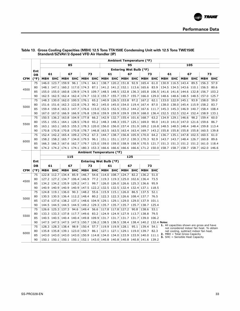
Performance Data
Table 13. Gross Cooling Capacities (MBH) 12.5 Tons TTA150E Condensing Unit with 12.5 Tons TWE150E Standard/SZVAV/2-Speed VFD Air Handler (IP)
CFM
EntDB
(°F)
Ambient Temperature (°F)85 95 105
Entering Wet Bulb (°F)61 67 73 61 67 73 61 67 73
MBH SHC MBH SHC MBH SHC MBH SHC MBH SHC MBH SHC MBH SHC MBH SHC MBH SHC
4500
75 146.0 123.7 159.9 96.1 174.1 64.1 138.7 120.2 151.8 92.9 165.4 61.0 130.9 116.5 143.4 89.5 156.3 57.980 148.1 147.1 160.2 117.0 174.3 87.1 141.2 141.2 152.1 113.6 165.6 83.9 134.5 134.5 143.6 110.1 156.5 80.685 155.0 155.0 160.8 139.9 174.5 109.7 148.5 148.5 152.8 136.3 165.8 106.5 141.6 141.6 144.6 132.8 156.7 103.290 162.5 162.5 162.4 162.4 174.7 132.3 155.7 155.7 155.7 155.7 166.0 129.0 148.6 148.6 148.5 148.5 157.0 125.7
5000
75 148.3 130.0 162.0 100.5 176.1 65.2 140.9 126.5 153.8 97.2 167.2 62.1 133.0 122.9 145.1 93.9 158.0 59.080 151.6 151.6 162.3 122.8 176.3 90.2 145.0 145.0 154.0 119.4 167.4 87.0 138.0 138.0 145.4 115.9 158.2 83.785 159.4 159.4 163.3 147.7 176.6 115.0 152.5 152.5 155.2 144.2 167.6 111.7 145.3 145.3 146.9 140.7 158.4 108.490 167.0 167.0 166.9 166.9 176.8 139.6 159.9 159.9 159.9 159.9 168.0 136.4 152.5 152.5 152.4 152.4 158.9 133.1
5500
75 150.5 136.2 163.8 104.9 177.8 66.2 142.9 132.7 155.4 101.6 168.7 63.2 134.9 129.1 146.6 98.2 159.4 60.080 155.1 155.1 164.1 128.5 178.0 93.2 148.3 148.3 155.7 125.1 169.0 90.0 141.0 141.0 147.0 121.6 159.6 86.785 163.1 163.1 165.5 155.3 178.3 120.0 156.0 156.0 157.4 151.9 169.2 116.8 148.5 148.5 148.4 148.4 159.8 113.490 170.8 170.8 170.8 170.8 178.7 146.8 163.5 163.5 163.4 163.4 169.7 143.2 155.8 155.8 155.8 155.8 160.5 139.8
6000
75 152.4 142.2 165.4 109.2 179.2 67.3 144.7 138.7 156.8 105.9 170.0 64.2 136.7 135.1 147.8 102.5 160.5 61.080 158.2 158.2 165.7 134.0 179.5 96.1 151.1 151.1 157.2 130.3 170.3 92.9 143.7 143.7 148.4 126.7 160.8 89.685 166.3 166.3 167.6 162.7 179.7 125.0 159.0 159.0 158.9 158.9 170.5 121.7 151.3 151.3 151.2 151.2 161.0 118.490 174.2 174.2 174.1 174.1 180.3 153.3 166.6 166.6 166.6 166.6 171.2 150.0 158.7 158.7 158.7 158.7 162.0 146.6
Ambient Temperature (°F)115 125
Ent Entering Wet Bulb (°F)DB 61 67 73 61 67 73
CFM (°F) MBH SHC MBH SHC MBH SHC MBH SHC MBH SHC MBH SHC
4500
75 122.8 112.7 134.4 85.9 146.7 54.6 114.0 108.7 124.7 82.2 136.2 51.080 127.2 127.2 134.7 106.4 146.9 77.2 119.3 119.3 125.0 102.6 136.4 73.585 134.2 134.2 135.9 129.2 147.1 99.7 126.0 126.0 126.6 125.3 136.6 95.990 140.9 140.9 140.9 140.9 147.5 122.2 132.5 132.5 132.4 132.4 137.1 118.5
5000
75 124.8 119.1 136.0 90.3 148.2 55.6 115.9 115.1 126.0 86.5 137.5 52.180 130.5 130.5 136.4 112.2 148.4 80.2 122.3 122.3 126.6 108.4 137.7 76.585 137.6 137.6 138.2 137.1 148.6 104.9 129.1 129.1 129.0 129.0 137.9 101.190 144.5 144.5 144.5 144.5 149.2 129.3 135.7 135.7 135.7 135.7 138.7 125.4
5500
75 126.6 125.3 137.3 94.6 149.4 56.6 117.8 117.8 127.2 90.8 138.6 53.180 133.3 133.3 137.8 117.7 149.6 83.2 124.9 124.9 127.9 113.7 138.8 79.585 140.5 140.5 140.4 140.4 149.8 109.9 131.7 131.7 131.7 131.7 139.0 106.290 147.5 147.5 147.5 147.5 150.7 136.2 138.5 138.5 138.4 138.4 140.2 132.4 Notes:
1. All capacities shown are gross and have not considered indoor fan heat. To obtain net cooling, subtract indoor fan heat.
2. MBH = Total Gross Capacity 3. SHC = Sensible Heat Capacity
6000
75 128.3 128.3 138.4 98.9 150.4 57.7 119.9 119.9 128.1 95.1 139.4 54.180 135.8 135.8 139.1 123.0 150.7 86.1 127.1 127.1 129.1 119.0 139.7 82.385 143.0 143.0 143.0 143.0 150.9 114.8 134.0 134.0 133.9 133.9 140.0 111.190 150.1 150.1 150.1 150.1 152.1 143.0 140.8 140.8 140.8 140.8 141.6 139.2
SS-PRC028-EN 33

Performance Data
Table 14. Gross Cooling Capacities (MBH) 15 Tons TTA180E Condensing Unit with 15 Tons TWE180E Standard/SZVAV/2-Speed VFD Air Handler (IP)
CFM
EntDB
(°F)
Ambient Temperature (°F)85 95 105
Entering Wet Bulb (°F)61 67 73 61 67 73 61 67 73
MBH SHC MBH SHC MBH SHC MBH SHC MBH SHC MBH SHC MBH SHC MBH SHC MBH SHC
5400
75 172.9 140.0 190.5 114.8 209.4 77.2 164.7 135.6 181.8 111.3 199.9 73.9 156.2 131.3 172.5 107.6 189.6 70.280 174.2 164.4 191.1 133.4 209.8 102.0 164.9 164.9 182.4 129.6 200.4 98.4 157.7 157.7 173.1 125.5 190.3 94.585 180.6 180.6 191.3 157.3 210.4 126.3 173.8 173.8 182.7 153.4 201.0 122.6 166.4 166.4 173.6 149.3 190.9 118.790 189.8 189.8 193.1 181.8 210.9 150.4 182.8 182.8 182.7 182.7 201.5 146.7 175.2 175.2 175.1 175.1 191.3 142.7
6000
75 175.6 145.8 193.5 120.3 212.3 78.7 167.5 141.8 184.6 116.7 202.6 75.2 158.8 137.5 175.0 113.0 192.0 71.480 176.5 176.5 194.2 139.2 212.9 105.2 169.6 169.6 185.3 135.4 203.3 101.5 162.7 159.3 175.7 131.3 192.8 97.685 185.9 185.9 194.6 165.1 213.6 131.5 178.8 178.8 185.9 161.2 203.9 127.8 171.1 171.1 176.5 157.0 193.5 123.990 195.5 195.5 195.3 195.3 214.1 157.7 188.1 188.1 188.0 188.0 204.5 153.9 180.2 180.2 180.9 177.3 194.0 149.9
6600
75 178.3 151.8 196.0 125.7 214.7 80.0 170.0 147.7 186.9 122.1 204.8 76.4 161.1 143.4 177.2 118.3 194.0 72.580 180.9 180.9 196.8 144.8 215.5 108.2 174.2 171.3 187.7 140.9 205.7 104.5 166.1 165.2 177.6 136.2 195.0 100.685 190.6 190.6 197.5 172.5 216.3 136.6 183.2 183.2 188.6 168.6 206.4 132.8 175.2 175.2 179.1 164.4 195.7 128.890 200.4 200.4 200.3 200.3 216.9 164.7 192.8 192.8 193.3 190.5 206.6 160.4 184.6 184.6 184.7 184.3 196.1 156.2
7200
75 180.6 157.5 198.3 131.0 216.8 81.0 172.2 153.4 189.0 127.4 206.7 77.1 163.2 149.1 179.0 123.6 195.8 73.180 185.1 182.7 199.1 150.1 217.7 111.1 177.4 177.0 189.4 145.7 207.7 107.4 169.3 169.3 179.5 141.2 196.9 103.485 194.7 194.7 200.1 179.6 218.6 141.4 187.1 187.1 191.1 175.7 208.5 137.6 178.8 178.8 181.6 171.6 197.7 133.690 204.8 204.8 205.2 203.1 218.9 170.8 197.0 197.0 196.9 196.9 208.9 166.8 188.5 188.5 188.4 188.4 198.2 162.6
Ambient Temperature (°F)115 125
Ent Entering Wet Bulb (°F)DB 61 67 73 61 67 73
CFM (°F) MBH SHC MBH SHC MBH SHC MBH SHC MBH SHC MBH SHC
5400
75 147.1 126.9 162.3 103.6 178.5 66.3 137.2 122.1 151.2 99.3 166.1 61.880 150.6 146.9 163.0 121.2 179.3 90.4 141.5 140.1 151.9 116.6 167.1 85.985 158.4 158.4 163.8 144.9 179.9 114.5 149.5 149.5 153.0 140.3 167.7 110.090 166.9 166.9 167.7 163.6 180.3 138.5 157.7 157.7 157.9 156.6 168.0 133.3
6000
75 149.5 133.0 164.6 109.0 180.5 67.3 139.4 128.2 153.2 104.6 168.0 62.680 154.2 153.0 165.0 126.4 181.6 93.4 145.0 145.0 153.7 121.4 169.1 88.985 162.7 162.7 166.5 152.6 182.3 119.6 153.4 153.4 153.3 153.3 169.8 115.190 171.6 171.6 171.7 170.8 182.5 145.1 161.9 161.9 161.8 161.8 170.3 140.3
6600
75 151.7 138.9 166.6 114.3 182.4 68.0 139.5 139.5 154.9 109.9 169.5 65.080 157.5 157.5 167.0 131.5 183.5 96.4 148.2 148.2 155.5 126.6 170.8 91.885 166.6 166.6 166.4 166.4 184.3 124.6 156.9 156.9 156.7 156.7 171.6 120.090 175.6 175.6 175.5 175.5 184.7 151.8 165.6 165.6 165.5 165.5 172.3 147.0 Notes:
1. All capacities shown are gross and have not considered indoor fan heat. To obtain net cooling, subtract indoor fan heat.
2. MBH = Total Gross Capacity 3. SHC = Sensible Heat Capacity
7200
75 153.7 144.6 168.2 119.6 183.9 70.5 142.1 142.1 156.4 113.8 170.8 66.380 160.6 160.6 168.8 136.6 185.2 99.2 151.0 151.0 157.2 131.6 172.3 94.685 169.9 169.9 169.8 169.8 186.0 129.3 159.9 159.9 160.8 155.6 172.7 123.990 179.2 179.2 179.1 179.1 186.7 158.2 168.8 168.8 168.7 168.7 174.1 153.4
34 SS-PRC028-EN

Performance Data
Table 15. Gross Cooling Capacities (MBH) 15 Tons TTA180E Condensing Unit with 20 Tons TWE240E Standard/SZVAV/2-Speed VFD Air Handler (IP)
CFM
EntDB
(°F)
Ambient Temperature (°F)85 95 105
Entering Wet Bulb (°F)61 67 73 61 67 73 61 67 73
MBH SHC MBH SHC MBH SHC MBH SHC MBH SHC MBH SHC MBH SHC MBH SHC MBH SHC
6400
75 185.4 161.3 203.8 127.6 223.7 82.9 176.7 157.2 194.2 123.9 213.4 79.4 167.5 152.8 184.0 119.9 202.2 75.480 189.9 186.9 204.3 153.2 224.1 113.8 181.9 181.1 194.7 149.2 213.8 110.0 173.5 173.5 184.4 144.6 202.7 106.085 199.5 199.5 205.5 183.8 224.7 144.4 191.7 191.7 196.2 179.8 214.3 140.5 183.4 183.4 186.4 175.7 203.2 136.590 209.9 209.9 210.6 207.7 225.2 174.9 201.9 201.9 202.1 201.9 214.7 170.7 193.3 193.3 193.2 193.2 203.8 166.5
6700
75 186.7 164.8 205.0 130.3 224.9 83.6 177.9 160.7 195.3 126.5 214.4 80.0 168.7 156.3 185.0 122.5 203.1 76.280 191.8 190.4 205.5 156.5 225.4 115.5 183.7 183.7 195.7 152.1 215.0 111.7 175.4 175.4 185.5 147.8 203.8 107.785 201.9 201.9 207.0 188.2 225.9 147.3 194.0 194.0 197.7 184.3 215.5 143.5 185.5 185.5 185.3 185.3 204.3 139.490 212.5 212.5 212.8 211.9 226.3 178.7 204.4 204.4 204.2 204.2 216.0 174.7 195.5 195.5 195.4 195.4 204.9 170.6
7000
75 187.9 168.3 206.1 133.0 226.0 84.3 179.1 164.1 196.4 129.2 215.4 80.5 169.9 159.8 185.9 125.2 204.0 76.980 193.5 193.5 206.5 159.4 226.5 117.3 185.7 185.7 196.8 155.2 216.0 113.4 177.3 177.3 186.5 150.9 204.7 109.485 204.2 204.2 208.5 192.5 227.1 150.2 196.1 196.1 199.1 188.6 216.6 146.3 187.5 187.5 187.3 187.3 205.2 142.290 214.9 214.9 214.8 214.8 227.6 182.6 206.6 206.6 206.5 206.5 217.2 178.7 197.6 197.6 197.5 197.5 206.1 174.5
7300
75 189.1 171.7 207.2 135.7 227.0 84.9 180.3 167.6 197.4 131.9 216.2 81.4 168.8 168.8 186.8 127.9 204.8 77.580 195.5 195.5 207.6 162.4 227.6 118.9 187.5 187.5 197.9 158.3 217.0 115.1 179.0 179.0 187.5 153.9 205.6 111.085 206.3 206.3 209.9 196.8 228.2 153.0 198.1 198.1 198.0 198.0 217.5 149.1 189.3 189.3 189.1 189.1 206.1 145.090 217.1 217.1 217.1 217.1 228.8 186.5 208.7 208.7 208.6 208.6 218.3 182.5 199.6 199.6 199.6 199.6 207.1 178.4
Ambient Temperature (°F)115 125
Ent Entering Wet Bulb (°F)DB 61 67 73 61 67 73
CFM (°F) MBH SHC MBH SHC MBH SHC MBH SHC MBH SHC MBH SHC
6400
75 157.7 148.3 172.9 115.6 190.0 71.5 145.8 145.8 160.8 111.0 176.7 67.180 164.7 164.7 173.5 140.1 190.7 101.7 154.9 154.9 161.5 135.2 177.5 97.085 174.3 174.3 174.1 174.1 191.2 132.2 164.2 164.2 165.2 159.6 178.0 127.590 183.9 183.9 183.8 183.8 192.0 162.1 173.4 173.4 173.3 173.3 179.1 157.4
6700
75 156.8 156.8 173.8 118.3 190.9 72.2 148.5 142.0 161.6 113.6 177.4 67.780 166.5 166.5 174.5 143.2 191.7 103.4 156.5 156.5 162.5 138.3 178.3 98.785 176.2 176.2 176.1 176.1 192.2 135.0 165.9 165.9 166.7 162.5 178.9 130.490 186.0 186.0 185.9 185.9 193.1 166.2 175.3 175.3 175.2 175.2 180.1 161.4
7000
75 158.4 158.4 174.7 120.9 191.7 72.8 149.7 144.3 162.3 116.3 178.1 68.480 168.2 168.2 175.4 146.3 192.5 105.1 158.0 158.0 163.3 141.3 179.1 100.485 178.1 178.0 179.2 174.4 193.0 137.9 167.6 167.6 168.0 165.4 179.4 132.690 187.9 187.9 187.8 187.8 194.1 170.1 177.1 177.1 177.0 177.0 181.2 165.3 Notes:
1. All capacities shown are gross and have not considered indoor fan heat. To obtain net cooling, subtract indoor fan heat.
2. MBH = Total Gross Capacity 3. SHC = Sensible Heat Capacity
7300
75 159.9 159.9 175.4 123.6 192.5 73.5 150.8 146.5 163.0 118.9 178.8 69.080 169.8 169.8 176.3 149.3 193.3 106.7 159.5 159.5 164.1 144.4 179.8 102.085 179.8 179.8 180.6 176.1 193.9 140.7 169.1 169.1 169.3 168.3 180.2 135.390 189.8 189.8 189.6 189.6 195.2 174.0 178.7 178.7 178.7 178.7 182.2 169.3
SS-PRC028-EN 35

Performance Data
Table 16. Gross Cooling Capacities (MBH) One Compressor - 15 Tons TTA180F Condensing Unit with 15 Tons TWE180E Standard/SZVAV/2-Speed VFD Air Handler (IP)
CFM
EntDB
(°F)
Ambient Temperature (°F)85 95 105
Entering Wet Bulb (°F)61 67 73 61 67 73 61 67 73
MBH SHC MBH SHC MBH SHC MBH SHC MBH SHC MBH SHC MBH SHC MBH SHC MBH SHC
5400
75 106.4 106.4 113.7 84.8 123.5 48.4 101.7 101.7 108.0 82.8 117.6 46.4 96.6 96.6 101.9 75.4 110.6 43.280 112.8 112.8 114.6 105.2 124.1 73.4 107.8 107.8 109.0 103.1 117.6 71.1 102.5 102.5 103.0 100.8 110.7 63.685 119.1 119.1 119.1 119.1 124.1 97.8 113.5 113.5 113.5 113.5 117.7 95.7 107.7 107.7 107.7 107.7 111.7 87.390 124.8 124.8 124.7 124.7 125.4 122.9 120.1 120.1 120.1 120.1 120.1 120.1 114.8 114.8 114.8 114.8 114.8 114.8
6000
75 108.4 108.4 114.7 89.6 124.3 49.7 103.6 103.6 108.9 87.7 118.4 46.6 99.5 99.5 102.7 78.9 111.3 44.280 114.9 114.9 115.9 111.0 124.9 76.6 109.9 109.9 110.3 108.9 118.4 74.3 104.0 104.0 104.0 104.0 111.4 63.685 121.0 121.0 121.0 121.0 125.1 103.0 115.5 115.5 115.5 115.5 119.9 101.3 109.5 109.5 108.8 108.8 114.4 110.290 127.4 127.4 127.4 127.4 127.3 127.3 122.4 122.4 122.4 122.4 122.3 122.3 116.9 116.9 116.9 116.9 116.9 116.9
6600
75 110.2 110.2 115.5 94.4 125.0 49.6 107.4 107.4 109.6 92.5 119.1 47.5 99.8 99.8 103.3 82.3 112.0 45.180 116.8 116.8 117.1 116.7 126.0 78.9 111.6 111.6 111.6 111.6 119.1 76.6 105.4 105.4 105.4 105.4 113.0 75.085 122.8 122.8 122.8 122.8 126.0 108.0 117.2 117.2 117.2 117.2 120.8 106.3 111.9 111.9 110.2 110.2 114.8 100.090 129.5 129.5 129.5 129.5 129.4 129.4 124.3 124.3 124.3 124.3 124.2 124.2 118.6 118.6 118.6 118.6 118.6 118.6
7200
75 111.4 111.4 116.3 99.1 125.6 52.2 106.6 106.6 110.3 97.3 119.6 48.4 101.0 101.0 103.9 85.6 113.0 48.180 118.6 118.6 118.5 118.5 126.5 81.5 112.9 112.9 112.9 112.9 119.6 79.3 106.6 106.6 106.6 106.6 114.1 76.085 125.5 125.5 125.4 125.4 126.8 112.8 119.9 119.9 119.8 119.8 121.6 105.0 112.7 112.7 112.1 112.1 115.8 100.590 131.8 131.8 131.8 131.8 131.2 131.2 125.9 125.9 125.9 125.9 125.9 125.9 120.1 120.1 120.1 120.1 120.1 120.1
Ambient Temperature (°F)115 125
Ent Entering Wet Bulb (°F)DB 61 67 73 61 67 73
CFM (°F) MBH SHC MBH SHC MBH SHC MBH SHC MBH SHC MBH SHC
5400
75 91.0 91.0 95.2 72.8 103.0 35.6 84.9 84.9 87.2 69.8 95.5 29.080 96.1 96.1 96.1 96.1 104.0 55.0 89.5 89.5 88.0 76.0 97.0 48.085 102.7 102.7 101.6 101.6 106.5 79.0 95.0 95.0 92.0 86.0 100.0 72.090 110.9 110.9 110.8 110.8 110.8 110.8 101.0 101.0 99.0 95.0 106.0 106.0
6000
75 92.6 92.6 95.5 76.2 103.6 36.1 85.2 85.2 87.7 73.3 87.8 70.080 97.6 97.6 97.6 97.6 104.0 60.9 89.1 89.1 89.8 89.8 90.4 80.785 103.7 103.7 102.5 102.5 106.0 85.8 95.3 95.3 94.4 94.4 95.0 91.490 110.7 110.7 110.6 110.6 110.6 110.6 103.0 103.0 101.9 101.9 102.1 102.1
6600
75 93.9 93.9 96.0 79.6 106.0 39.9 87.4 87.4 89.0 76.4 99.8 35.080 100.0 100.0 98.6 98.6 107.1 69.8 93.6 93.6 92.7 92.7 101.0 65.185 106.1 106.1 104.0 104.0 108.9 93.7 99.8 99.8 97.3 97.3 102.9 88.290 112.2 112.2 112.2 112.2 112.2 112.2 106.0 106.0 105.0 105.0 106.1 106.1 Notes:
1. All capacities shown are gross and have not considered indoor fan heat. To obtain net cooling, subtract indoor fan heat.
2. MBH = Total Gross Capacity 3. SHC = Sensible Heat Capacity
7200
75 95.0 95.0 96.5 82.8 105.9 41.0 87.0 87.0 89.8 79.1 98.4 33.980 101.3 101.3 99.3 99.3 107.3 67.4 93.9 93.9 92.5 92.5 99.4 59.885 107.7 107.7 105.1 105.1 108.8 93.1 100.5 100.5 97.6 97.6 101.3 85.490 113.5 113.5 113.5 113.5 113.5 113.5 106.2 106.2 106.5 106.5 105.2 107.0
36 SS-PRC028-EN

Performance Data
Table 17. Gross Cooling Capacities (MBH) Both Compressors - 15 Tons TTA180F Condensing Unit with 15 Tons TWE180E Standard/SZVAV/2-Speed VFD Air Handler (IP)
CFM
EntDB
(°F)
Ambient Temperature (°F)85 95 105
Entering Wet Bulb (°F)61 67 73 61 67 73 61 67 73
MBH SHC MBH SHC MBH SHC MBH SHC MBH SHC MBH SHC MBH SHC MBH SHC MBH SHC
5400
75 174.2 141.0 190.9 115.5 208.8 77.2 166.3 136.8 182.6 112.1 199.6 73.9 158.1 132.6 173.5 108.5 189.6 70.580 175.4 164.8 191.7 134.1 209.4 102.1 168.2 161.1 183.4 130.4 200.3 98.6 160.4 157.1 174.4 126.5 190.4 94.885 181.7 181.7 192.0 157.9 210.2 126.6 175.0 175.0 183.7 154.1 201.1 123.0 167.8 167.8 174.7 150.0 191.2 119.290 190.6 190.6 193.8 181.9 210.9 150.9 183.8 183.8 185.8 178.2 201.7 147.3 176.4 176.4 177.3 174.2 191.8 143.5
6000
75 176.8 146.7 193.8 121.0 211.5 78.6 169.0 142.7 185.2 117.6 202.0 75.3 160.5 138.5 176.0 113.9 191.8 71.680 179.1 173.2 194.7 139.9 212.4 105.3 171.7 169.4 186.1 136.2 203.0 101.8 163.7 163.7 176.8 132.3 192.8 98.085 186.8 186.8 195.1 165.4 213.3 131.8 179.9 179.9 186.5 161.5 203.9 128.2 172.4 172.4 177.5 157.4 193.7 124.490 196.1 196.1 197.7 191.7 214.0 158.2 188.9 188.9 189.7 187.9 204.6 154.6 181.1 181.1 181.0 181.0 194.4 150.7
6600
75 179.3 152.4 196.3 126.4 213.8 80.0 171.3 148.4 187.5 123.0 204.1 76.4 162.7 144.2 178.0 119.3 193.6 72.780 182.4 181.1 197.3 145.5 214.9 108.3 174.9 174.9 188.4 141.7 205.3 104.7 167.4 167.4 178.6 136.9 194.9 100.985 191.3 191.3 197.8 172.5 215.9 136.9 184.2 184.2 189.2 168.7 206.2 133.2 176.4 176.4 180.0 164.5 195.9 129.490 200.8 200.8 201.4 201.1 216.6 165.2 193.4 193.4 193.3 193.3 206.6 160.5 185.3 185.3 185.2 185.2 196.2 156.3
7200
75 181.5 157.8 198.4 131.8 215.6 81.0 173.3 153.8 189.5 128.3 205.7 77.4 164.7 149.6 179.8 124.6 195.0 74.480 185.5 185.5 199.0 150.0 217.1 111.2 178.4 178.4 190.1 146.0 207.3 107.6 170.6 170.6 180.5 141.7 196.7 103.885 195.3 195.3 200.3 179.4 218.1 141.7 187.9 187.9 191.6 175.5 208.3 138.0 179.8 179.8 182.3 171.4 197.7 134.190 205.1 205.1 205.0 205.0 218.5 170.6 197.4 197.4 197.3 197.3 208.7 166.7 189.0 189.0 188.9 188.9 198.2 162.5
Ambient Temperature (°F)115 125
Ent Entering Wet Bulb (°F)DB 61 67 73 61 67 73
CFM (°F) MBH SHC MBH SHC MBH SHC MBH SHC MBH SHC MBH SHC
5400
75 149.2 128.2 163.8 104.6 178.8 66.6 139.5 123.4 153.0 100.5 166.8 62.480 151.9 151.9 164.6 122.4 179.7 90.9 143.4 143.4 153.8 117.9 167.9 86.585 160.1 160.1 165.1 145.6 180.5 115.2 151.3 151.3 154.7 140.9 168.7 110.890 168.2 168.2 168.1 168.1 181.1 139.4 159.1 159.1 159.1 159.1 169.0 134.0
6000
75 151.5 134.1 166.0 110.0 180.7 67.7 141.7 129.3 155.0 105.8 168.3 64.080 155.8 155.8 166.8 128.1 181.9 93.9 147.0 147.0 155.5 122.5 169.8 89.685 164.2 164.2 167.8 153.0 182.8 120.3 155.0 155.0 157.2 148.2 170.7 115.990 172.6 172.6 172.6 172.6 183.1 145.5 163.1 163.1 163.1 163.1 171.1 140.6
6600
75 153.6 139.7 167.8 115.4 182.1 69.4 143.6 134.8 156.6 111.1 169.7 65.380 159.2 159.2 168.4 132.4 183.8 96.9 150.0 150.0 157.2 127.5 171.5 92.585 167.8 167.8 170.2 160.1 184.7 125.3 158.3 158.3 159.4 155.2 172.4 120.890 176.5 176.5 176.4 176.4 185.1 151.8 166.6 166.6 166.5 166.5 172.9 147.0 Notes:
1. All capacities shown are gross and have not considered indoor fan heat. To obtain net cooling, subtract indoor fan heat.
2. MBH = Total Gross Capacity 3. SHC = Sensible Heat Capacity
7200
75 155.5 145.1 169.4 120.7 183.6 70.7 145.4 140.2 158.0 116.4 171.0 66.680 162.1 162.1 170.1 137.2 185.3 99.7 152.7 152.7 158.7 132.2 172.8 95.285 171.0 171.0 172.4 166.9 186.3 130.0 161.2 161.2 161.1 161.1 173.4 124.390 179.9 179.9 179.8 179.8 186.8 158.0 169.7 169.7 169.7 169.7 174.6 153.1
SS-PRC028-EN 37
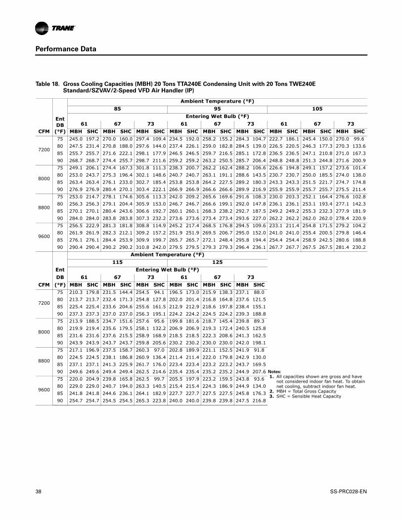
Performance Data
Table 18. Gross Cooling Capacities (MBH) 20 Tons TTA240E Condensing Unit with 20 Tons TWE240E Standard/SZVAV/2-Speed VFD Air Handler (IP)
CFM
EntDB
(°F)
Ambient Temperature (°F)85 95 105
Entering Wet Bulb (°F)61 67 73 61 67 73 61 67 73
MBH SHC MBH SHC MBH SHC MBH SHC MBH SHC MBH SHC MBH SHC MBH SHC MBH SHC
7200
75 245.0 197.2 270.0 160.0 297.4 109.4 234.5 192.0 258.2 155.2 284.3 104.7 222.7 186.1 245.4 150.0 270.0 99.680 247.5 231.4 270.8 188.0 297.6 144.0 237.4 226.1 259.0 182.8 284.5 139.0 226.5 220.5 246.3 177.3 270.3 133.685 255.7 255.7 271.6 222.1 298.1 177.9 246.5 246.5 259.7 216.5 285.1 172.8 236.5 236.5 247.1 210.8 271.0 167.390 268.7 268.7 274.4 255.7 298.7 211.6 259.2 259.2 263.2 250.5 285.7 206.4 248.8 248.8 251.3 244.8 271.6 200.9
8000
75 249.1 206.1 274.4 167.3 301.8 111.3 238.3 200.7 262.2 162.4 288.2 106.6 226.6 194.8 249.1 157.2 273.6 101.480 253.0 243.7 275.3 196.4 302.1 148.6 240.7 240.7 263.1 191.1 288.6 143.5 230.7 230.7 250.0 185.5 274.0 138.085 263.4 263.4 276.1 233.0 302.7 185.4 253.8 253.8 264.2 227.5 289.2 180.3 243.3 243.3 251.5 221.7 274.7 174.890 276.9 276.9 280.4 270.1 303.4 222.1 266.9 266.9 266.6 266.6 289.9 216.9 255.9 255.9 255.7 255.7 275.5 211.4
8800
75 253.0 214.7 278.1 174.6 305.6 113.3 242.0 209.2 265.6 169.6 291.6 108.3 230.0 203.3 252.1 164.4 276.6 102.880 256.3 256.3 279.1 204.4 305.9 153.0 246.7 246.7 266.6 199.1 292.0 147.8 236.1 236.1 253.1 193.4 277.1 142.385 270.1 270.1 280.4 243.6 306.6 192.7 260.1 260.1 268.3 238.2 292.7 187.5 249.2 249.2 255.3 232.3 277.9 181.990 284.0 284.0 283.8 283.8 307.3 232.2 273.6 273.6 273.4 273.4 293.6 227.0 262.2 262.2 262.0 262.0 278.4 220.9
9600
75 256.5 222.9 281.3 181.8 308.8 114.9 245.2 217.4 268.5 176.8 294.5 109.6 233.1 211.4 254.8 171.5 279.2 104.280 261.9 261.9 282.3 212.1 309.2 157.2 251.9 251.9 269.5 206.7 295.0 152.0 241.0 241.0 255.4 200.5 279.8 146.485 276.1 276.1 284.4 253.9 309.9 199.7 265.7 265.7 272.1 248.4 295.8 194.4 254.4 254.4 258.9 242.5 280.6 188.890 290.4 290.4 290.2 290.2 310.8 242.0 279.5 279.5 279.3 279.3 296.4 236.1 267.7 267.7 267.5 267.5 281.4 230.2
Ambient Temperature (°F)115 125
Ent Entering Wet Bulb (°F)DB 61 67 73 61 67 73
CFM (°F) MBH SHC MBH SHC MBH SHC MBH SHC MBH SHC MBH SHC
7200
75 210.3 179.8 231.5 144.4 254.5 94.1 196.5 173.0 215.9 138.3 237.1 88.080 213.7 213.7 232.4 171.3 254.8 127.8 202.0 201.4 216.8 164.8 237.6 121.585 225.4 225.4 233.6 204.6 255.6 161.5 212.9 212.9 218.6 197.8 238.4 155.190 237.3 237.3 237.0 237.0 256.3 195.1 224.2 224.2 224.5 224.2 239.3 188.8
8000
75 213.9 188.5 234.7 151.6 257.6 95.6 199.8 181.6 218.7 145.4 239.8 89.380 219.9 219.4 235.6 179.5 258.1 132.2 206.9 206.9 219.3 172.4 240.5 125.885 231.6 231.6 237.6 215.5 258.9 168.9 218.5 218.5 222.3 208.6 241.3 162.590 243.9 243.9 243.7 243.7 259.8 205.6 230.2 230.2 230.0 230.0 242.0 198.1
8800
75 217.1 196.9 237.5 158.7 260.3 97.0 202.8 189.9 221.1 152.5 241.9 91.880 224.5 224.5 238.1 186.8 260.9 136.4 211.4 211.4 222.0 179.8 242.9 130.085 237.1 237.1 241.3 225.9 261.7 176.0 223.4 223.4 223.2 223.2 243.7 169.590 249.6 249.6 249.4 249.4 262.5 214.6 235.4 235.4 235.2 235.2 244.9 207.6 Notes:
1. All capacities shown are gross and have not considered indoor fan heat. To obtain net cooling, subtract indoor fan heat.
2. MBH = Total Gross Capacity 3. SHC = Sensible Heat Capacity
9600
75 220.0 204.9 239.8 165.8 262.5 99.7 205.5 197.9 223.2 159.5 243.8 93.680 229.0 229.0 240.7 194.0 263.3 140.5 215.4 215.4 224.3 186.9 244.9 134.085 241.8 241.8 244.6 236.1 264.1 182.9 227.7 227.7 227.5 227.5 245.8 176.390 254.7 254.7 254.5 254.5 265.3 223.8 240.0 240.0 239.8 239.8 247.5 216.8
38 SS-PRC028-EN

Performance Data
Table 19. Gross Cooling Capacities (MBH) One Compressor - 20 Tons TTA240F Condensing Unit with 20 Tons TWE240E Standard/SZVAV/2-Speed VFD Air Handler (IP)
CFM
EntDB
(°F)
Ambient Temperature (°F)85 95 105
Entering Wet Bulb (°F)61 67 73 61 67 73 61 67 73
MBH SHC MBH SHC MBH SHC MBH SHC MBH SHC MBH SHC MBH SHC MBH SHC MBH SHC
7200
75 143.7 136.8 158.0 116.7 173.8 67.2 137.4 133.9 150.6 113.9 165.4 64.5 130.5 130.5 142.5 109.8 156.3 61.680 151.0 151.0 158.2 129.6 173.9 93.8 145.0 145.0 150.8 126.6 165.6 90.9 138.4 138.4 142.7 123.2 156.5 87.785 159.6 159.6 160.0 158.0 174.2 122.2 153.3 153.3 153.2 153.2 165.8 119.3 146.3 146.3 146.2 146.2 156.7 116.190 168.2 168.2 168.1 168.1 174.3 149.8 161.6 161.6 161.5 161.5 166.0 146.7 154.2 154.2 154.2 154.2 157.1 143.4
8000
75 145.9 143.5 159.7 122.5 175.4 69.0 139.6 139.6 152.1 119.7 166.9 66.3 133.1 133.1 143.8 116.6 157.6 63.480 154.3 154.3 160.0 135.6 175.7 97.2 148.1 148.1 152.4 132.4 167.1 94.2 141.2 141.2 144.1 129.1 157.8 91.085 163.1 163.1 163.0 163.0 175.9 127.8 156.6 156.6 156.5 156.5 167.3 124.5 149.3 149.3 149.2 149.2 158.0 121.190 172.0 172.0 171.9 171.9 176.2 157.4 165.1 165.1 165.0 165.0 167.9 154.3 157.4 157.4 157.3 157.3 158.9 151.0
8800
75 148.2 148.2 161.2 129.3 176.8 70.8 142.1 142.1 153.4 126.5 168.1 68.0 135.4 135.4 145.0 123.4 158.7 65.180 157.2 157.2 161.4 141.2 177.1 100.3 150.7 150.7 153.7 138.1 168.4 97.3 143.6 143.6 145.5 134.7 159.0 94.185 166.2 166.2 166.1 166.1 177.3 132.7 159.4 159.4 159.3 159.3 168.6 129.6 151.9 151.9 151.8 151.8 159.1 126.190 175.3 175.3 175.2 175.2 178.0 164.7 168.1 168.1 168.0 168.0 169.6 161.6 160.1 160.1 160.0 160.0 160.6 158.2
9600
75 150.5 150.5 162.4 136.1 178.0 72.5 144.2 144.2 154.6 133.3 169.2 69.8 137.3 137.3 145.9 129.7 159.6 66.880 159.7 159.7 162.8 146.6 178.4 103.4 153.1 153.1 155.1 143.5 169.5 100.3 145.7 145.7 146.8 140.1 159.9 97.185 168.9 168.9 168.8 168.8 178.6 137.6 161.9 161.9 161.8 161.8 169.7 134.4 154.1 154.1 154.1 154.1 160.1 131.090 178.2 178.2 178.1 178.1 179.7 171.7 170.7 170.7 170.6 170.6 171.2 168.6 162.1 162.1 162.1 162.1 162.0 162.0
Ambient Temperature (°F)115 125
Ent Entering Wet Bulb (°F)DB 61 67 73 61 67 73
CFM (°F) MBH SHC MBH SHC MBH SHC MBH SHC MBH SHC MBH SHC
7200
75 123.6 123.6 133.7 106.5 146.4 58.5 115.8 115.8 124.0 103.0 135.6 55.180 131.1 131.1 133.9 119.6 146.7 84.3 122.9 122.9 124.5 115.8 135.9 80.785 138.6 138.6 138.5 138.5 146.8 112.2 130.0 130.0 129.9 129.9 136.1 108.490 146.1 146.1 146.1 146.1 147.6 139.9 137.0 137.0 137.0 137.0 137.4 136.0
8000
75 125.9 125.9 134.8 113.3 147.5 60.2 117.9 117.9 124.9 109.3 136.6 56.880 133.6 133.6 135.3 125.5 147.8 87.6 125.2 125.2 125.9 121.6 136.9 83.985 141.3 141.3 141.2 141.2 148.0 117.5 132.4 132.4 132.3 132.3 137.1 113.690 148.9 148.9 148.9 148.9 149.4 147.4 139.5 139.5 139.5 139.5 139.4 139.4
8800
75 127.9 127.9 135.8 119.6 148.5 61.9 119.7 119.7 125.8 115.8 137.4 58.580 135.8 135.8 136.7 131.1 148.8 90.7 127.1 127.1 127.0 127.0 137.7 87.085 143.6 143.6 143.5 143.5 149.0 122.5 134.4 134.4 134.4 134.4 137.9 118.590 151.4 151.4 151.3 151.3 151.2 151.2 141.6 141.6 141.6 141.6 141.5 141.5 Notes:
1. All capacities shown are gross and have not considered indoor fan heat. To obtain net cooling, subtract indoor fan heat.
2. MBH = Total Gross Capacity 3. SHC = Sensible Heat Capacity
9600
75 129.7 129.7 136.7 126.1 149.3 63.6 121.3 121.3 126.6 98.1 138.1 60.280 137.7 137.7 138.0 136.5 149.7 93.6 128.8 128.8 128.7 128.7 138.5 89.985 145.6 145.6 145.6 145.6 149.9 127.3 136.2 136.2 136.1 136.1 138.7 123.390 152.7 152.7 152.7 152.7 152.7 152.7 143.5 143.5 143.4 143.4 143.3 143.3
SS-PRC028-EN 39

Performance Data
Table 20. Gross Cooling Capacities (MBH) Both Compressors - 20 Tons TTA240F Condensing Unit with 20 Tons TWE240E Standard/SZVAV/2-Speed VFD Air Handler (IP)
CFM
EntDB
(°F)
Ambient Temperature (°F)85 95 105
Entering Wet Bulb (°F)61 67 73 61 67 73 61 67 73
MBH SHC MBH SHC MBH SHC MBH SHC MBH SHC MBH SHC MBH SHC MBH SHC MBH SHC
7200
75 237.0 189.3 261.7 156.2 288.4 106.0 226.8 184.2 250.2 151.6 275.6 101.5 215.5 178.8 237.7 146.6 261.6 96.680 238.8 221.9 262.0 180.5 288.4 139.0 229.0 216.9 250.6 175.5 275.6 134.0 218.4 211.6 238.1 170.2 261.7 128.885 246.3 246.3 262.4 212.6 288.5 170.9 237.5 237.5 250.9 207.6 275.7 165.9 227.8 227.8 238.6 202.2 261.9 160.790 258.6 258.6 264.4 244.8 288.8 202.7 249.5 249.5 253.6 239.8 276.0 197.7 239.4 239.4 241.9 234.5 262.2 192.4
8000
75 241.2 197.7 265.9 163.6 292.9 108.1 230.5 192.6 254.1 158.8 279.6 103.4 218.9 187.2 241.2 153.8 265.2 98.580 244.0 233.2 266.4 188.2 292.8 143.2 234.0 228.2 254.5 183.2 279.6 138.2 223.2 222.9 241.7 177.7 265.3 132.985 253.6 253.6 266.7 223.0 293.0 177.9 244.4 244.4 255.1 218.0 279.7 172.8 234.2 234.2 242.4 212.3 265.5 167.590 266.4 266.4 270.1 258.1 293.3 212.4 256.7 256.7 259.0 253.0 280.0 207.3 246.2 246.2 246.0 246.0 265.8 201.9
8800
75 244.7 205.8 269.5 170.8 296.4 110.0 233.8 200.7 257.3 166.0 282.9 104.9 222.0 194.9 244.1 160.9 268.2 99.680 248.7 244.1 270.0 195.6 296.5 147.2 237.7 237.7 257.9 190.5 282.9 142.2 227.5 227.5 244.7 185.0 268.3 136.885 260.0 260.0 270.7 233.1 296.7 184.5 250.4 250.4 258.8 227.6 283.1 179.4 239.8 239.8 246.1 222.1 268.5 174.090 273.2 273.2 275.2 270.8 297.0 221.6 263.1 263.1 263.0 263.0 283.5 216.5 252.1 252.1 252.0 252.0 268.9 211.0
9600
75 247.7 213.2 272.6 178.0 299.7 111.3 236.8 208.0 260.2 173.1 285.7 106.2 225.0 202.4 246.7 168.0 270.7 100.980 252.3 252.3 273.2 202.6 299.7 151.1 242.7 242.7 260.7 197.4 285.7 146.0 232.1 232.1 247.3 191.9 270.8 140.685 265.7 265.7 274.3 242.3 299.9 190.9 255.7 255.7 262.3 237.1 286.0 185.7 244.7 244.7 249.4 231.5 271.1 180.390 279.3 279.3 279.1 279.1 300.3 230.4 268.8 268.8 268.6 268.6 286.4 225.3 257.3 257.3 257.2 257.2 271.5 219.8
Ambient Temperature (°F)115 125
Ent Entering Wet Bulb (°F)DB 61 67 73 61 67 73
CFM (°F) MBH SHC MBH SHC MBH SHC MBH SHC MBH SHC MBH SHC
7200
75 203.2 173.0 224.0 141.1 246.4 91.3 189.6 166.5 208.8 135.1 229.5 85.580 206.9 205.9 224.5 164.4 246.5 123.1 194.3 194.3 209.3 158.0 229.6 116.985 217.1 217.1 225.3 196.5 246.7 155.0 204.9 204.9 210.4 189.8 229.9 148.890 228.2 228.2 229.3 228.7 247.1 186.7 215.6 215.6 215.4 215.4 230.2 180.4
8000
75 206.4 181.1 227.1 148.3 249.5 92.6 192.8 174.5 211.5 142.2 232.1 87.380 211.5 211.5 227.6 171.9 249.7 127.2 199.3 199.3 212.0 165.5 232.3 120.985 222.9 222.9 228.9 206.4 249.9 161.8 210.2 210.2 213.9 199.9 232.6 155.590 234.4 234.4 234.3 234.3 250.2 196.1 221.1 221.1 221.0 221.0 233.0 189.8
8800
75 209.5 188.9 229.7 155.4 252.2 93.9 195.6 182.3 213.7 149.3 234.3 89.180 216.3 216.3 230.3 179.1 252.3 131.1 203.6 203.6 214.3 172.6 234.5 124.885 228.1 228.1 232.3 216.1 252.6 168.2 214.8 214.8 217.1 209.5 234.9 161.990 239.9 239.9 239.7 239.7 252.9 205.2 226.0 226.0 225.9 225.9 235.6 199.0 Notes:
1. All capacities shown are gross and have not considered indoor fan heat. To obtain net cooling, subtract indoor fan heat.
2. MBH = Total Gross Capacity 3. SHC = Sensible Heat Capacity
9600
75 212.2 196.3 232.0 162.4 254.3 96.8 198.1 189.7 215.7 156.3 236.2 90.980 220.5 220.5 232.6 185.9 254.5 134.8 207.4 207.4 216.3 179.4 236.5 128.585 232.6 232.6 235.4 225.4 254.9 174.5 218.8 218.8 220.0 218.8 236.9 168.190 244.6 244.6 244.5 244.5 255.5 214.1 230.3 230.3 230.2 230.2 237.8 207.0
40 SS-PRC028-EN

Performance Data
Table 21. Gross Cooling Capacities (MBH) One Compressor - 25 Tons TTA300F Condensing Unit with 25 Tons TWE300E Air Handler (IP)
CFM
EntDB
(°F)
Ambient Temperature (°F)85 95 105
Entering Wet Bulb (°F)61 67 73 61 67 73 61 67 73
MBH SHC MBH SHC MBH SHC MBH SHC MBH SHC MBH SHC MBH SHC MBH SHC MBH SHC
9000
75 179.9 179.9 192.5 140.7 207.7 81.1 171.8 171.8 182.6 136.7 196.8 77.0 163.1 163.1 172.3 132.5 185.4 73.280 190.8 190.8 194.7 175.0 210.3 122.3 182.2 182.2 184.9 170.9 199.3 118.0 173.1 173.1 174.7 166.6 188.0 113.785 201.8 201.8 201.8 201.8 212.4 163.5 192.8 192.8 192.7 192.7 201.3 159.4 183.2 183.2 183.2 183.2 189.9 155.190 212.9 212.9 212.9 212.9 215.2 205.4 203.4 203.4 203.4 203.4 204.5 201.2 193.4 193.4 193.3 193.3 193.3 193.3
10000
75 183.4 183.4 194.3 138.4 209.0 82.3 175.0 175.0 184.2 134.2 197.8 78.5 166.1 166.1 173.7 129.8 186.2 74.780 194.6 194.6 196.9 184.4 212.1 126.7 185.7 185.7 187.0 180.2 200.9 122.4 176.3 176.3 176.8 175.9 189.4 118.085 206.0 206.0 205.9 205.9 214.3 171.9 196.6 196.6 196.5 196.5 203.1 167.7 186.7 186.7 186.6 186.6 191.6 163.490 217.4 217.4 217.4 217.4 218.1 217.6 207.5 207.5 207.5 207.5 207.3 207.3 197.1 197.1 197.0 197.0 196.9 196.9
11000
75 186.4 186.4 195.8 143.6 209.8 83.8 177.7 177.7 185.5 139.3 198.5 80.0 168.5 168.5 174.8 134.9 186.7 76.180 197.8 197.8 199.0 193.4 213.6 130.9 188.6 188.6 188.5 188.5 202.3 126.6 179.0 179.0 178.9 178.9 190.6 122.085 209.4 209.4 209.4 209.4 216.1 180.0 199.7 199.7 199.7 199.7 204.7 175.8 189.5 189.5 189.5 189.5 193.0 171.490 221.2 221.2 221.1 221.1 221.0 221.0 210.9 210.9 210.9 210.9 210.7 210.7 200.1 200.1 200.1 200.1 200.0 200.0
12000
75 188.9 188.9 197.1 148.5 210.4 85.2 180.0 180.0 186.6 144.2 198.9 81.4 170.6 170.6 175.9 139.8 187.7 77.680 200.6 200.6 200.5 200.5 214.9 134.9 191.1 191.1 191.1 191.1 203.4 130.5 181.2 181.2 181.1 181.1 191.6 125.985 212.4 212.4 212.4 212.4 217.6 187.8 202.4 202.4 202.4 202.4 206.2 183.5 192.0 192.0 191.9 191.9 194.4 179.090 224.4 224.4 224.4 224.4 224.2 224.2 213.8 213.8 213.8 213.8 213.8 213.8 202.7 202.7 202.7 202.7 202.7 202.7
Ambient Temperature (°F)115 125
Ent Entering Wet Bulb (°F)DB 61 67 73 61 67 73
CFM (°F) MBH SHC MBH SHC MBH SHC MBH SHC MBH SHC MBH SHC
9000
75 154.0 154.0 161.4 128.1 173.3 69.7 144.0 144.0 149.8 123.4 160.6 67.180 163.5 163.5 164.1 162.1 176.1 109.1 153.0 153.0 153.0 153.0 163.3 104.185 173.1 173.1 173.1 173.1 178.0 150.6 162.0 162.0 162.0 162.0 165.3 145.890 182.7 182.7 182.7 182.7 182.6 182.6 171.0 171.0 171.0 171.0 171.0 171.0
10000
75 156.6 156.6 162.6 125.2 174.0 71.4 146.3 146.3 150.8 120.3 161.0 67.380 166.4 166.4 166.3 166.3 177.3 113.3 155.5 155.5 155.4 155.4 164.4 108.285 176.1 176.1 176.1 176.1 179.5 158.8 164.7 164.7 164.6 164.6 166.6 153.990 185.9 185.9 185.9 185.9 185.9 185.9 173.8 173.8 173.8 173.8 173.8 173.8
11000
75 158.8 158.8 163.7 130.3 174.4 73.1 148.2 148.2 151.8 125.2 161.5 67.980 168.7 168.7 168.6 168.6 178.4 117.3 157.5 157.5 157.5 157.5 165.1 113.185 178.7 178.7 178.7 178.7 180.9 166.7 166.9 166.9 166.8 166.8 167.9 161.790 188.7 188.7 188.6 188.6 188.6 188.6 176.2 176.2 176.1 176.1 176.1 176.1 Notes:
1. All capacities shown are gross and have not considered indoor fan heat. To obtain net cooling, subtract indoor fan heat.
2. MBH = Total Gross Capacity 3. SHC = Sensible Heat Capacity
12000
75 160.6 160.6 164.6 135.1 174.9 73.5 149.8 149.8 152.6 130.0 161.7 68.380 170.7 170.7 170.7 170.7 179.2 121.1 159.3 159.3 159.3 159.3 165.7 117.985 180.9 180.9 180.8 180.8 182.1 174.3 168.8 168.8 168.8 168.8 169.1 169.090 191.0 191.0 191.0 191.0 190.9 190.9 178.2 178.2 178.2 178.2 178.2 178.2
SS-PRC028-EN 41
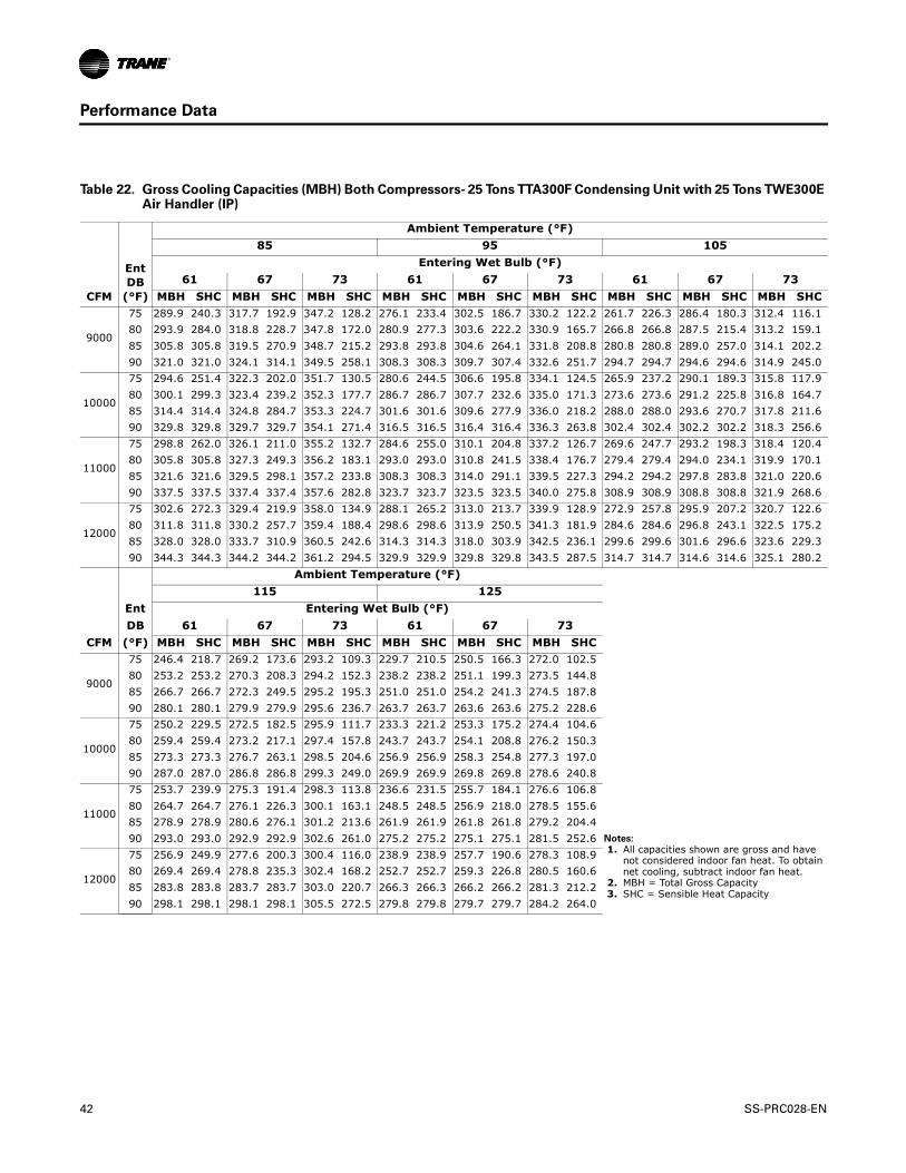
Performance Data
Table 22. Gross Cooling Capacities (MBH) Both Compressors- 25 Tons TTA300F Condensing Unit with 25 Tons TWE300E Air Handler (IP)
CFM
EntDB
(°F)
Ambient Temperature (°F)85 95 105
Entering Wet Bulb (°F)61 67 73 61 67 73 61 67 73
MBH SHC MBH SHC MBH SHC MBH SHC MBH SHC MBH SHC MBH SHC MBH SHC MBH SHC
9000
75 289.9 240.3 317.7 192.9 347.2 128.2 276.1 233.4 302.5 186.7 330.2 122.2 261.7 226.3 286.4 180.3 312.4 116.180 293.9 284.0 318.8 228.7 347.8 172.0 280.9 277.3 303.6 222.2 330.9 165.7 266.8 266.8 287.5 215.4 313.2 159.185 305.8 305.8 319.5 270.9 348.7 215.2 293.8 293.8 304.6 264.1 331.8 208.8 280.8 280.8 289.0 257.0 314.1 202.290 321.0 321.0 324.1 314.1 349.5 258.1 308.3 308.3 309.7 307.4 332.6 251.7 294.7 294.7 294.6 294.6 314.9 245.0
10000
75 294.6 251.4 322.3 202.0 351.7 130.5 280.6 244.5 306.6 195.8 334.1 124.5 265.9 237.2 290.1 189.3 315.8 117.980 300.1 299.3 323.4 239.2 352.3 177.7 286.7 286.7 307.7 232.6 335.0 171.3 273.6 273.6 291.2 225.8 316.8 164.785 314.4 314.4 324.8 284.7 353.3 224.7 301.6 301.6 309.6 277.9 336.0 218.2 288.0 288.0 293.6 270.7 317.8 211.690 329.8 329.8 329.7 329.7 354.1 271.4 316.5 316.5 316.4 316.4 336.3 263.8 302.4 302.4 302.2 302.2 318.3 256.6
11000
75 298.8 262.0 326.1 211.0 355.2 132.7 284.6 255.0 310.1 204.8 337.2 126.7 269.6 247.7 293.2 198.3 318.4 120.480 305.8 305.8 327.3 249.3 356.2 183.1 293.0 293.0 310.8 241.5 338.4 176.7 279.4 279.4 294.0 234.1 319.9 170.185 321.6 321.6 329.5 298.1 357.2 233.8 308.3 308.3 314.0 291.1 339.5 227.3 294.2 294.2 297.8 283.8 321.0 220.690 337.5 337.5 337.4 337.4 357.6 282.8 323.7 323.7 323.5 323.5 340.0 275.8 308.9 308.9 308.8 308.8 321.9 268.6
12000
75 302.6 272.3 329.4 219.9 358.0 134.9 288.1 265.2 313.0 213.7 339.9 128.9 272.9 257.8 295.9 207.2 320.7 122.680 311.8 311.8 330.2 257.7 359.4 188.4 298.6 298.6 313.9 250.5 341.3 181.9 284.6 284.6 296.8 243.1 322.5 175.285 328.0 328.0 333.7 310.9 360.5 242.6 314.3 314.3 318.0 303.9 342.5 236.1 299.6 299.6 301.6 296.6 323.6 229.390 344.3 344.3 344.2 344.2 361.2 294.5 329.9 329.9 329.8 329.8 343.5 287.5 314.7 314.7 314.6 314.6 325.1 280.2
Ambient Temperature (°F)115 125
Ent Entering Wet Bulb (°F)DB 61 67 73 61 67 73
CFM (°F) MBH SHC MBH SHC MBH SHC MBH SHC MBH SHC MBH SHC
9000
75 246.4 218.7 269.2 173.6 293.2 109.3 229.7 210.5 250.5 166.3 272.0 102.580 253.2 253.2 270.3 208.3 294.2 152.3 238.2 238.2 251.1 199.3 273.5 144.885 266.7 266.7 272.3 249.5 295.2 195.3 251.0 251.0 254.2 241.3 274.5 187.890 280.1 280.1 279.9 279.9 295.6 236.7 263.7 263.7 263.6 263.6 275.2 228.6
10000
75 250.2 229.5 272.5 182.5 295.9 111.7 233.3 221.2 253.3 175.2 274.4 104.680 259.4 259.4 273.2 217.1 297.4 157.8 243.7 243.7 254.1 208.8 276.2 150.385 273.3 273.3 276.7 263.1 298.5 204.6 256.9 256.9 258.3 254.8 277.3 197.090 287.0 287.0 286.8 286.8 299.3 249.0 269.9 269.9 269.8 269.8 278.6 240.8
11000
75 253.7 239.9 275.3 191.4 298.3 113.8 236.6 231.5 255.7 184.1 276.6 106.880 264.7 264.7 276.1 226.3 300.1 163.1 248.5 248.5 256.9 218.0 278.5 155.685 278.9 278.9 280.6 276.1 301.2 213.6 261.9 261.9 261.8 261.8 279.2 204.490 293.0 293.0 292.9 292.9 302.6 261.0 275.2 275.2 275.1 275.1 281.5 252.6 Notes:
1. All capacities shown are gross and have not considered indoor fan heat. To obtain net cooling, subtract indoor fan heat.
2. MBH = Total Gross Capacity 3. SHC = Sensible Heat Capacity
12000
75 256.9 249.9 277.6 200.3 300.4 116.0 238.9 238.9 257.7 190.6 278.3 108.980 269.4 269.4 278.8 235.3 302.4 168.2 252.7 252.7 259.3 226.8 280.5 160.685 283.8 283.8 283.7 283.7 303.0 220.7 266.3 266.3 266.2 266.2 281.3 212.290 298.1 298.1 298.1 298.1 305.5 272.5 279.8 279.8 279.7 279.7 284.2 264.0
42 SS-PRC028-EN

Performance Data
Table 23. Gross Cooling Capacities (MBH) 6 Tons TTA073D Condensing Unit Only (IP)
Outdoor Temp (°F)
Suction Temperature (°F)30 35 40 45 50 55
65Head Press (psig) 248.4 262.2 269.4 276.9 284.7 292.9
Capacity (Btuh/1000) 66.4 73.5 81.0 88.7 96.7 105.0Unit Power (kW) 4.4 4.4 4.4 4.5 4.5 4.6
75Head Press (psig) 292.6 299.8 307.3 315.0 323.1 331.5
Capacity (Btuh/1000) 62.6 69.4 76.4 83.8 91.3 99.1Unit Power (kW) 4.7 4.8 4.8 4.9 5.0 5.0
85Head Press (psig) 333.3 340.8 348.6 356.7 365.1 373.7
Capacity (Btuh/1000) 58.5 65.0 71.7 78.7 85.8 93.1Unit Power (kW) 5.2 5.3 5.3 5.4 5.5 5.5
95Head Press (psig) 377.5 385.4 393.5 401.9 410.6 419.4
Capacity (Btuh/1000) 54.2 60.4 66.8 73.4 80.1 87.0Unit Power (kW) 5.7 5.8 5.9 5.9 6.0 6.1
105Head Press (psig) 425.2 433.5 442.1 450.9 459.8 469.0
Capacity (Btuh/1000) 49.7 55.6 61.7 67.9 74.3 80.8Unit Power (kW) 6.4 6.4 6.5 6.5 6.6 6.7
115Head Press (psig) 476.7 485.5 494.4 503.5 512.7 522.1
Capacity (Btuh/1000) 45.0 50.6 56.3 62.3 68.3 74.4Unit Power (kW) 7.0 7.1 7.1 7.2 7.3 7.3
125Head Press (psig) 531.8 541.1 550.3 559.6 569.0 578.4
Capacity (Btuh/1000) 40.0 45.3 50.7 56.3 61.9 67.5Unit Power (kW) 7.8 7.8 7.9 7.9 8.0 8.0
Note: Performance data calculated at 15°F subcooling and 15°F superheat and does not include capacity loss due to refrigerant lines.
Figure 4. TTA073D Capacity Curve
Capacity Curves - Condensing Unit Only
35
45
55
65
75
85
95
105
115
125
135
25 30 35 40 45 50 55 60 65 70 75
Saturated Suction Temperature (F)
Gro
ss C
oolin
g Ca
paci
ty (M
BH
)
65758595105115125
COM
PRES
SOR
HIG
H S
UC
TIO
N L
IMIT
IND
OO
R CO
IL F
ROST
LIM
IT
SS-PRC028-EN 43
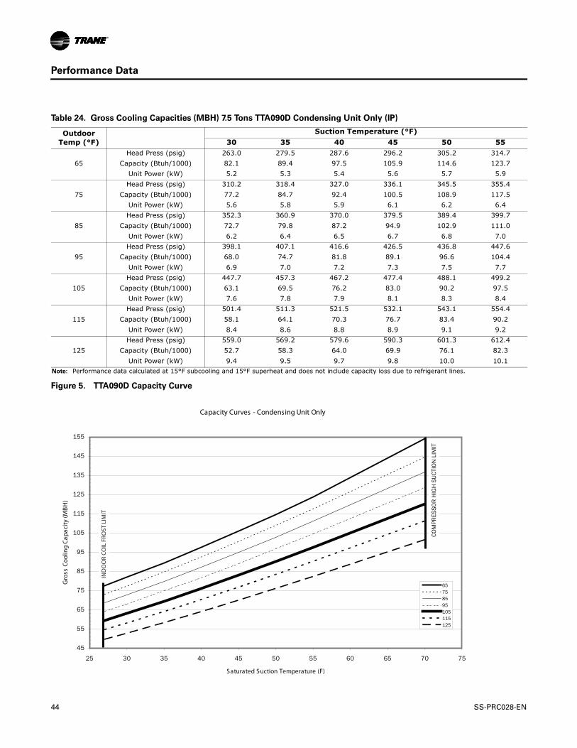
Performance Data
Table 24. Gross Cooling Capacities (MBH) 7.5 Tons TTA090D Condensing Unit Only (IP)
Outdoor Temp (°F)
Suction Temperature (°F)30 35 40 45 50 55
65Head Press (psig) 263.0 279.5 287.6 296.2 305.2 314.7
Capacity (Btuh/1000) 82.1 89.4 97.5 105.9 114.6 123.7Unit Power (kW) 5.2 5.3 5.4 5.6 5.7 5.9
75Head Press (psig) 310.2 318.4 327.0 336.1 345.5 355.4
Capacity (Btuh/1000) 77.2 84.7 92.4 100.5 108.9 117.5Unit Power (kW) 5.6 5.8 5.9 6.1 6.2 6.4
85Head Press (psig) 352.3 360.9 370.0 379.5 389.4 399.7
Capacity (Btuh/1000) 72.7 79.8 87.2 94.9 102.9 111.0Unit Power (kW) 6.2 6.4 6.5 6.7 6.8 7.0
95Head Press (psig) 398.1 407.1 416.6 426.5 436.8 447.6
Capacity (Btuh/1000) 68.0 74.7 81.8 89.1 96.6 104.4Unit Power (kW) 6.9 7.0 7.2 7.3 7.5 7.7
105Head Press (psig) 447.7 457.3 467.2 477.4 488.1 499.2
Capacity (Btuh/1000) 63.1 69.5 76.2 83.0 90.2 97.5Unit Power (kW) 7.6 7.8 7.9 8.1 8.3 8.4
115Head Press (psig) 501.4 511.3 521.5 532.1 543.1 554.4
Capacity (Btuh/1000) 58.1 64.1 70.3 76.7 83.4 90.2Unit Power (kW) 8.4 8.6 8.8 8.9 9.1 9.2
125Head Press (psig) 559.0 569.2 579.6 590.3 601.3 612.4
Capacity (Btuh/1000) 52.7 58.3 64.0 69.9 76.1 82.3Unit Power (kW) 9.4 9.5 9.7 9.8 10.0 10.1
Note: Performance data calculated at 15°F subcooling and 15°F superheat and does not include capacity loss due to refrigerant lines.
Figure 5. TTA090D Capacity Curve
Capacity Curves - Condensing Unit Only
45
55
65
75
85
95
105
115
125
135
145
155
25 30 35 40 45 50 55 60 65 70 75
Saturated Suction Temperature (F)
Gro
ss C
oolin
g Ca
paci
ty (M
BH
)
65758595105115125
COM
PRES
SOR
HIG
H S
UCT
ION
LIM
IT
IND
OO
R CO
IL F
ROST
LIM
IT
44 SS-PRC028-EN

Performance Data
Table 25. Gross Cooling Capacities (MBH) 10 Tons TTA120D Condensing Unit Only (IP)
Outdoor Temp (°F)
Suction Temperature (°F)30 35 40 45 50 55
65Head Press (psig) 256.3 263.3 270.7 278.4 286.5 295.0
Capacity (Btuh/1000) 99.2 110.4 122.0 134.0 146.4 159.2Unit Power (kW) 6.6 6.7 6.9 7.1 7.2 7.4
75Head Press (psig) 293.3 300.6 308.2 316.1 324.4 333.0
Capacity (Btuh/1000) 94.0 104.6 115.6 126.9 138.7 150.7Unit Power (kW) 7.2 7.3 7.5 7.7 7.8 8.0
85Head Press (psig) 333.8 341.3 349.2 357.4 365.8 374.5
Capacity (Btuh/1000) 88.5 98.4 108.9 119.6 130.7 142.0Unit Power (kW) 7.9 8.0 8.2 8.4 8.5 8.7
95Head Press (psig) 377.9 385.8 393.9 402.3 410.9 419.7
Capacity (Btuh/1000) 82.6 92.0 101.9 112.1 122.5 133.1Unit Power (kW) 8.7 8.9 9.0 9.2 9.3 9.5
105Head Press (psig) 425.8 434.0 442.4 451.1 459.9 469.0
Capacity (Btuh/1000) 76.4 85.3 94.6 104.2 114.1 124.0Unit Power (kW) 9.6 9.8 9.9 10.1 10.2 10.4
115Head Press (psig) 477.7 486.3 495.0 504.0 513.0 522.2
Capacity (Btuh/1000) 69.9 78.3 87.0 96.1 105.3 114.6Unit Power (kW) 10.7 10.8 11.0 11.1 11.2 11.4
125Head Press (psig) 533.7 542.8 551.9 561.1 570.2 579.5
Capacity (Btuh/1000) 63.0 70.9 79.1 87.5 96.1 104.7Unit Power (kW) 11.8 12.0 12.1 12.2 12.3 12.4
Note: Performance data calculated at 15°F subcooling and 15°F superheat and does not include capacity loss due to refrigerant lines.
Figure 6. TTA120D Capacity Curve
Capacity Curves - Condensing Unit Only
55
65
75
85
95
105
115
125
135
145
155
165
175
185
195
205
25 30 35 40 45 50 55 60 65 70 75
Saturated Suction Temperature (F)
Gro
ss C
oolin
g Ca
paci
ty (M
BH
)
65758595105115125
COM
PRES
SOR
HIG
H S
UCT
ION
LIM
IT
IND
OO
R C
OIL
FR
OST
LIM
IT
SS-PRC028-EN 45

Performance Data
Table 26. Gross Cooling Capacities (MBH) 10 Tons TTA120E Condensing Unit Only (IP)
Outdoor Temp (°F)
Suction Temperature (°F)30 35 40 45 50 55
65Head Press (psig) 253.8 260.4 267.5 274.9 282.6 290.7
Capacity (Btuh/1000) 99.4 110.4 121.8 133.7 145.9 158.5Unit Power (kW) 6.4 6.5 6.6 6.7 6.8 6.9
75Head Press (psig) 290.3 297.2 304.4 312.0 319.9 328.1
Capacity (Btuh/1000) 93.7 104.0 114.8 126.0 137.5 149.3Unit Power (kW) 7.0 7.1 7.2 7.3 7.4 7.6
85Head Press (psig) 330.4 337.5 345.0 352.8 360.8 369.2
Capacity (Btuh/1000) 87.6 97.4 107.6 118.1 129.0 140.0Unit Power (kW) 7.7 7.8 8.0 8.1 8.2 8.4
95Head Press (psig) 374.2 381.5 389.2 397.2 405.4 413.9
Capacity (Btuh/1000) 81.3 90.4 100.0 110.0 120.2 130.6Unit Power (kW) 8.6 8.7 8.9 9.0 9.2 9.3
105Head Press (psig) 421.7 429.3 437.3 445.5 453.9 462.6
Capacity (Btuh/1000) 74.7 83.3 92.3 101.7 111.2 121.0Unit Power (kW) 9.7 9.8 9.9 10.0 10.2 10.3
115Head Press (psig) 473.3 481.3 489.5 498.0 506.5 515.3
Capacity (Btuh/1000) 67.7 75.9 84.3 93.1 102.1 111.2Unit Power (kW) 10.8 11.0 11.1 11.2 11.3 11.4
125Head Press (psig) 529.1 537.5 546.0 554.6 563.4 572.3
Capacity (Btuh/1000) 60.5 68.2 76.0 84.2 92.6 101.0Unit Power (kW) 12.1 12.3 12.4 12.5 12.6 12.7
Note: Performance data calculated at 15°F subcooling and 15°F superheat and does not include capacity loss due to refrigerant lines.
Figure 7. TTA120E Capacity Curve
Capacity Curves - Condensing Unit Only
50
60
70
80
90
100
110
120
130
140
150
160
170
180
190
200
25 30 35 40 45 50 55 60 65 70 75
Saturated Suction Temperature (F)
Gro
ss C
oolin
g Ca
paci
ty (M
BH
)
65758595105115125
COM
PRES
SOR
HIG
H S
UCT
ION
LIM
IT
IND
OO
R CO
IL F
ROST
LIM
IT
46 SS-PRC028-EN
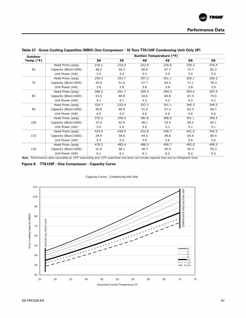
Performance Data
Table 27. Gross Cooling Capacities (MBH) One Compressor - 10 Tons TTA120F Condensing Unit Only (IP)
Outdoor Temp (°F)
Suction Temperature (°F)30 35 40 45 50 55
65Head Press (psig) 216.1 219.4 222.9 226.6 230.3 234.4
Capacity (Btuh/1000) 48.2 54.2 60.8 67.7 74.7 82.3Unit Power (kW) 3.5 3.5 3.5 3.5 3.5 3.5
75Head Press (psig) 250.3 253.7 257.3 261.1 265.1 269.2
Capacity (Btuh/1000) 45.9 51.6 57.7 64.3 71.1 78.3Unit Power (kW) 3.8 3.8 3.8 3.8 3.8 3.9
85Head Press (psig) 288.2 291.7 295.4 299.3 303.4 307.5
Capacity (Btuh/1000) 43.4 48.9 54.6 60.8 67.3 74.0Unit Power (kW) 4.1 4.1 4.2 4.2 4.2 4.2
95Head Press (psig) 329.7 333.4 337.2 341.1 345.3 349.5
Capacity (Btuh/1000) 40.8 46.0 51.4 57.2 63.3 69.7Unit Power (kW) 4.5 4.5 4.6 4.6 4.6 4.6
105Head Press (psig) 375.2 378.9 382.8 386.9 391.1 395.5
Capacity (Btuh/1000) 37.9 42.9 48.1 53.5 59.2 65.1Unit Power (kW) 5.0 5.0 5.0 5.1 5.1 5.1
115Head Press (psig) 424.6 428.5 432.6 436.7 441.0 445.5
Capacity (Btuh/1000) 34.9 39.6 44.5 49.6 54.9 60.4Unit Power (kW) 5.5 5.5 5.6 5.6 5.6 5.6
125Head Press (psig) 478.3 482.4 486.5 490.7 495.0 499.3
Capacity (Btuh/1000) 31.6 36.1 40.7 45.4 50.3 55.3Unit Power (kW) 6.1 6.1 6.1 6.2 6.2 6.2
Note: Performance data calculated at 15°F subcooling and 15°F superheat and does not include capacity loss due to refrigerant lines.
Figure 8. TTA120F - One Compressor - Capacity Curve
Capacity Curves - Condensing Unit Only
20
30
40
50
60
70
80
90
100
110
25 30 35 40 45 50 55 60 65 70 75
Saturated Suction Temperature (F)
Gro
ss C
oolin
g Ca
paci
ty (M
BH
)
65758595105115125
COM
PRES
SOR
HIG
H S
UCT
ION
LIM
IT
IND
OO
R CO
IL F
ROST
LIM
IT
SS-PRC028-EN 47

Performance Data
Table 28. Gross Cooling Capacities (MBH) Both Compressors - 10 Tons TTA120F Condensing Unit Only (IP)
Outdoor Temp (°F)
Suction Temperature (°F)30 35 40 45 50 55
65Head Press (psig) 255.3 262.3 269.6 277.3 285.3 293.7
Capacity (Btuh/1000) 100.9 112.0 123.6 135.8 148.3 161.3Unit Power (kW) 6.5 6.6 6.7 6.8 7.0 7.1
75Head Press (psig) 291.9 299.1 306.6 314.5 322.7 331.3
Capacity (Btuh/1000) 95.7 106.2 117.3 128.7 140.6 152.9Unit Power (kW) 7.2 7.3 7.4 7.6 7.7 7.9
85Head Press (psig) 331.9 339.4 347.2 355.3 363.7 372.5
Capacity (Btuh/1000) 90.2 100.2 110.6 121.5 132.8 144.3Unit Power (kW) 8.0 8.1 8.3 8.4 8.6 8.7
95Head Press (psig) 375.4 383.2 391.3 399.6 408.3 417.2
Capacity (Btuh/1000) 84.4 93.9 103.8 114.1 124.7 135.5Unit Power (kW) 9.0 9.1 9.2 9.4 9.5 9.6
105Head Press (psig) 422.5 430.6 439.0 447.6 456.5 465.6
Capacity (Btuh/1000) 78.2 87.3 96.6 106.3 116.3 126.5Unit Power (kW) 10.0 10.1 10.3 10.4 10.5 10.7
115Head Press (psig) 473.4 481.9 490.6 499.4 508.5 517.7
Capacity (Btuh/1000) 71.8 80.4 89.2 98.4 107.7 117.2Unit Power (kW) 11.2 11.3 11.4 11.5 11.6 11.8
125Head Press (psig) 527.9 536.8 545.8 554.9 564.1 573.3
Capacity (Btuh/1000) 65.0 73.1 81.4 89.9 98.6 107.4Unit Power (kW) 12.4 12.5 12.6 12.7 12.8 12.9
Note: Performance data calculated at 15°F subcooling and 15°F superheat and does not include capacity loss due to refrigerant lines.
Figure 9. TTA120F - Both Compressors - Capacity Curve
Capacity Curves - Condensing Unit Only
50
60
70
80
90
100
110
120
130
140
150
160
170
180
190
200
210
25 30 35 40 45 50 55 60 65 70 75
Saturated Suction Temperature (F)
Gro
ss C
oolin
g Ca
paci
ty (M
BH
)
65758595105115125
IND
OO
R C
OIL
FR
OST
COM
PRES
SOR
HIG
H S
UCT
ION
LIM
IT
48 SS-PRC028-EN

Performance Data
Table 29. Gross Cooling Capacities (MBH) 12.5 Tons TTA150E Condensing Unit Only (IP)
Outdoor Temp (°F)
Suction Temperature (°F)30 35 40 45 50 55
65Head Press (psig) 271.8 279.9 288.4 297.2 306.4 316.1
Capacity (Btuh/1000) 131.3 145.2 159.6 174.5 189.8 205.4Unit Power (kW) 9.0 9.1 9.2 9.3 9.5 9.6
75Head Press (psig) 309.7 318.0 326.8 335.9 345.4 355.2
Capacity (Btuh/1000) 123.8 137.0 150.6 164.7 179.1 193.7Unit Power (kW) 9.8 9.9 10.1 10.2 10.4 10.5
85Head Press (psig) 350.9 359.6 368.6 378.0 387.8 397.8
Capacity (Btuh/1000) 115.8 128.3 141.2 154.5 168.1 181.9Unit Power (kW) 10.7 10.9 11.0 11.2 11.4 11.6
95Head Press (psig) 395.5 404.6 414.0 423.6 433.6 443.9
Capacity (Btuh/1000) 107.3 119.2 131.5 144.0 156.9 169.9Unit Power (kW) 11.8 12.0 12.1 12.3 12.5 12.6
105Head Press (psig) 443.7 453.3 463.1 473.2 483.5 494.0
Capacity (Btuh/1000) 98.3 109.7 121.4 133.3 145.4 157.7Unit Power (kW) 13.1 13.2 13.4 13.5 13.7 13.8
115Head Press (psig) 495.8 505.8 516.0 526.5 537.2 547.9
Capacity (Btuh/1000) 89.0 99.8 110.9 122.2 133.6 145.1Unit Power (kW) 14.4 14.6 14.7 14.9 15.0 15.1
125Head Press (psig) 551.8 562.5 573.2 583.8 594.7 605.6
Capacity (Btuh/1000) 79.2 89.4 99.9 110.5 121.2 131.9Unit Power (kW) 15.9 16.0 16.2 16.3 16.4 16.5
Note: Performance data calculated at 15°F subcooling and 15°F superheat and does not include capacity loss due to refrigerant lines.
Figure 10. TTA150E Capacity Curve
Capacity Curves - Condensing Unit Only
70
80
90
100
110
120
130
140
150
160
170
180
190
200
210
220
230
240
250
260
25 30 35 40 45 50 55 60 65 70 75
Saturated Suction Temperature (F)
Gro
ss C
oolin
g Ca
paci
ty (M
BH
)
65758595105115125
COM
PRES
SOR
HIG
H S
UCT
ION
LIM
IT
IND
OO
R CO
IL F
ROST
LIM
IT
SS-PRC028-EN 49

Performance Data
Table 30. Gross Cooling Capacities (MBH) 15 Tons TTA180E Condensing Unit Only (IP)
Outdoor Temp (°F)
Suction Temperature (°F)30 35 40 45 50 55
65Head Press (psig) 239.0 243.9 249.0 254.5 260.2 266.2
Capacity (Btuh/1000) 160.0 176.7 194.3 212.8 231.8 252.0Unit Power (kW) 10.6 10.8 11.0 11.2 11.4 11.6
75Head Press (psig) 274.6 279.8 285.2 290.9 296.9 303.2
Capacity (Btuh/1000) 150.8 166.9 183.9 201.7 220.2 239.4Unit Power (kW) 11.4 11.6 11.8 12.0 12.2 12.5
85Head Press (psig) 313.9 319.3 325.0 330.9 337.2 343.6
Capacity (Btuh/1000) 141.5 156.7 173.0 190.1 207.8 226.2Unit Power (kW) 12.3 12.5 12.8 13.0 13.2 13.5
95Head Press (psig) 356.8 362.5 368.4 374.6 381.0 387.7
Capacity (Btuh/1000) 131.8 146.3 161.7 178.0 194.9 212.4Unit Power (kW) 13.5 13.7 13.9 14.1 14.4 14.6
105Head Press (psig) 403.5 409.4 415.4 421.8 428.4 435.3
Capacity (Btuh/1000) 121.7 135.4 149.9 165.3 181.3 197.9Unit Power (kW) 14.8 15.0 15.2 15.4 15.7 15.9
115Head Press (psig) 454.2 460.3 466.5 472.9 479.7 486.7
Capacity (Btuh/1000) 111.2 124.1 137.6 152.0 167.0 182.5Unit Power (kW) 16.3 16.5 16.7 16.9 17.1 17.3
125Head Press (psig) 508.9 515.0 521.3 527.8 534.5 541.5
Capacity (Btuh/1000) 100.1 112.0 124.6 137.7 151.7 166.1Unit Power (kW) 18.0 18.1 18.3 18.5 18.7 18.9
Note: Performance data calculated at 15°F subcooling and 15°F superheat and does not include capacity loss due to refrigerant lines.
Figure 11. TTA180E Capacity Curve
Capacity Curves - Condensing Unit Only
90100110120130140150160170180190200210220230240250260270280290300310320
25 30 35 40 45 50 55 60 65 70 75
Saturated Suction Temperature (F)
Gro
ss C
oolin
g Ca
paci
ty (M
BH
)
65758595105115125
COM
PRES
SOR
HIG
H S
UCT
ION
LIM
IT
IND
OO
R CO
IL F
ROST
LIM
IT
50 SS-PRC028-EN

Performance Data
Table 31. Gross Cooling Capacities (MBH) One Compressor - 15 Tons TTA180F Condensing Unit Only (IP)
Outdoor Temp (°F)
Suction Temperature (°F)30 35 40 45 50 55
65Head Press (psig) 209.0 211.2 213.6 216.1 218.6 221.4
Capacity (Btuh/1000) 80.6 89.0 98.0 107.4 117.1 127.6Unit Power (kW) 6.2 6.2 6.3 6.4 6.5 6.5
75Head Press (psig) 243.0 245.3 247.8 250.4 253.2 256.1
Capacity (Btuh/1000) 76.5 84.7 93.4 102.5 112.0 122.0Unit Power (kW) 6.5 6.5 6.6 6.7 6.8 6.9
85Head Press (psig) 280.7 283.2 285.8 288.6 291.5 294.5
Capacity (Btuh/1000) 72.4 80.2 88.6 97.3 106.6 116.2Unit Power (kW) 6.9 6.9 7.0 7.1 7.2 7.2
95Head Press (psig) 322.4 325.0 327.8 330.6 333.7 336.8
Capacity (Btuh/1000) 68.0 75.5 83.5 91.9 100.8 110.0Unit Power (kW) 7.4 7.4 7.5 7.6 7.7 7.7
105Head Press (psig) 368.2 370.9 373.7 376.7 379.8 383.1
Capacity (Btuh/1000) 63.5 70.6 78.2 86.2 94.6 103.4Unit Power (kW) 8.0 8.0 8.1 8.2 8.2 8.3
115Head Press (psig) 418.2 421.1 423.9 427.0 430.2 433.5
Capacity (Btuh/1000) 58.8 65.5 72.5 80.1 88.0 96.3Unit Power (kW) 8.7 8.7 8.8 8.9 8.9 9.0
125Head Press (psig) 472.9 475.8 478.7 481.7 485.0 488.3
Capacity (Btuh/1000) 53.7 59.9 66.5 73.5 80.9 88.6Unit Power (kW) 9.5 9.5 9.6 9.6 9.7 9.7
Note: Performance data calculated at 15°F subcooling and 15°F superheat and does not include capacity loss due to refrigerant lines.
Figure 12. TTA180F - One Compressor - Capacity Curve
Capacity Curves - Condensing Unit Only
40
50
60
70
80
90
100
110
120
130
140
150
160
170
25 30 35 40 45 50 55 60 65 70 75
Saturated Suction Temperature (F)
Gro
ss C
oolin
g Ca
paci
ty (M
BH
)
65758595105115125
COM
PRES
SOR
HIG
H S
UCT
ION
LIM
IT
IND
OO
R CO
IL F
ROST
LIM
IT
SS-PRC028-EN 51
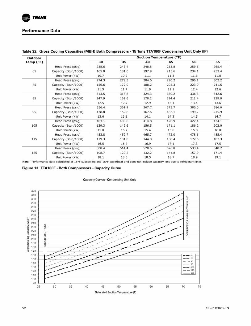
Performance Data
Table 32. Gross Cooling Capacities (MBH) Both Compressors - 15 Tons TTA180F Condensing Unit Only (IP)
Outdoor Temp (°F)
Suction Temperature (°F)30 35 40 45 50 55
65Head Press (psig) 238.6 243.4 248.5 253.8 259.5 265.4
Capacity (Btuh/1000) 165.0 181.0 197.9 215.6 234.1 253.4Unit Power (kW) 10.7 10.9 11.1 11.3 11.6 11.8
75Head Press (psig) 274.3 279.3 284.6 290.2 296.1 302.2
Capacity (Btuh/1000) 156.6 172.0 188.2 205.3 223.0 241.5Unit Power (kW) 11.5 11.7 11.9 12.1 12.4 12.6
85Head Press (psig) 313.5 318.8 324.3 330.2 336.3 342.6
Capacity (Btuh/1000) 147.9 162.6 178.2 194.4 211.4 229.0Unit Power (kW) 12.5 12.7 12.9 13.1 13.4 13.6
95Head Press (psig) 356.4 361.9 367.7 373.7 380.0 386.6
Capacity (Btuh/1000) 138.8 152.8 167.6 183.1 199.2 215.9Unit Power (kW) 13.6 13.8 14.1 14.3 14.5 14.7
105Head Press (psig) 403.1 408.8 414.8 420.9 427.4 434.1
Capacity (Btuh/1000) 129.3 142.6 156.5 171.1 186.2 202.0Unit Power (kW) 15.0 15.2 15.4 15.6 15.8 16.0
115Head Press (psig) 453.8 459.7 465.7 472.0 478.6 485.4
Capacity (Btuh/1000) 119.3 131.8 144.8 158.4 172.6 187.3Unit Power (kW) 16.5 16.7 16.9 17.1 17.3 17.5
125Head Press (psig) 508.4 514.4 520.5 526.8 533.4 540.2
Capacity (Btuh/1000) 108.7 120.2 132.2 144.8 157.9 171.4Unit Power (kW) 18.1 18.3 18.5 18.7 18.9 19.1
Note: Performance data calculated at 15°F subcooling and 15°F superheat and does not include capacity loss due to refrigerant lines.
Figure 13. TTA180F - Both Compressors - Capacity Curve
90100110120130140150160170180190200210220230240250260270280290300310320
25 30 35 40 45 50 55 60 65 70 75
GGro
ss C
oolin
g C
apac
ity (M
BH
)
SSaturated Suction Temperature (F)
CCapacity Curves -- CCondensing Unit Only
65
75
85
95
105
115
125
IND
OO
R C
OIL
FR
OST
CO
MPR
ESSO
R H
IGH
SU
CTI
ON
LIM
IT
52 SS-PRC028-EN

Performance Data
Table 33. Gross Cooling Capacities (MBH) 20 Tons TTA240E Condensing Unit Only (IP)
Outdoor Temp (°F)
Suction Temperature (°F)30 35 40 45 50 55
65Head Press (psig) 270.6 278.9 287.7 297.0 306.7 316.8
Capacity (Btuh/1000) 240.3 265.6 292.1 319.9 348.8 378.7Unit Power (kW) 16.3 16.8 17.3 17.8 18.3 18.9
75Head Press (psig) 308.8 317.5 326.6 336.2 346.1 356.5
Capacity (Btuh/1000) 228.7 252.7 277.8 304.1 331.4 359.6Unit Power (kW) 17.6 18.0 18.6 19.1 19.7 20.2
85Head Press (psig) 350.6 359.6 369.0 378.8 389.0 399.6
Capacity (Btuh/1000) 216.3 238.9 262.7 287.5 313.2 339.7Unit Power (kW) 19.0 19.5 20.1 20.6 21.2 21.8
95Head Press (psig) 396.0 405.2 414.9 424.9 435.4 446.2
Capacity (Btuh/1000) 203.1 224.4 246.7 270.0 294.1 319.0Unit Power (kW) 20.7 21.2 21.8 22.3 22.9 23.5
105Head Press (psig) 445.1 454.7 464.7 475.0 485.7 496.7
Capacity (Btuh/1000) 189.1 209.1 230.0 251.8 274.3 297.5Unit Power (kW) 22.7 23.2 23.7 24.2 24.8 25.3
115Head Press (psig) 498.3 508.2 518.4 528.9 539.7 550.8
Capacity (Btuh/1000) 174.3 192.9 212.4 232.6 253.5 274.9Unit Power (kW) 24.8 25.3 25.8 26.3 26.9 27.4
125Head Press (psig) 555.5 565.7 576.0 586.6 597.4 608.4
Capacity (Btuh/1000) 158.5 175.7 193.6 212.1 231.2 250.6Unit Power (kW) 27.1 27.6 28.1 28.6 29.1 29.6
Note: Performance data calculated at 15°F subcooling and 15°F superheat and does not include capacity loss due to refrigerant lines.
Figure 14. TTA240E Capacity Curve
Capacity Curves - Condensing Unit Only
140
160
180
200
220
240
260
280
300
320
340
360
380
400
420
25 30 35 40 45 50 55 60
Saturated Suction Temperature (F)
Gro
ss C
oolin
g Ca
paci
ty (M
BH
)
65758595105115125
COM
PRES
SOR
HIG
H S
UCT
ION
LIM
IT
IND
OO
R CO
IL F
ROST
LIM
IT
SS-PRC028-EN 53
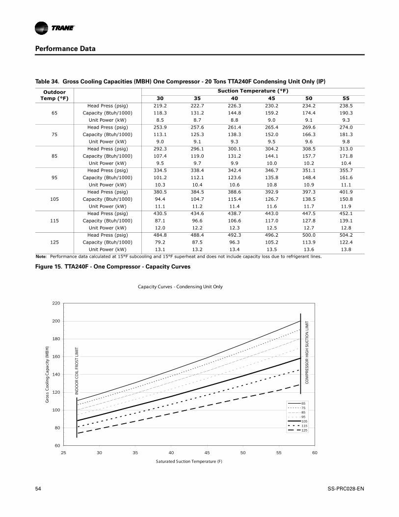
Performance Data
Table 34. Gross Cooling Capacities (MBH) One Compressor - 20 Tons TTA240F Condensing Unit Only (IP)
Outdoor Temp (°F)
Suction Temperature (°F)30 35 40 45 50 55
65Head Press (psig) 219.2 222.7 226.3 230.2 234.2 238.5
Capacity (Btuh/1000) 118.3 131.2 144.8 159.2 174.4 190.3Unit Power (kW) 8.5 8.7 8.8 9.0 9.1 9.3
75Head Press (psig) 253.9 257.6 261.4 265.4 269.6 274.0
Capacity (Btuh/1000) 113.1 125.3 138.3 152.0 166.3 181.3Unit Power (kW) 9.0 9.1 9.3 9.5 9.6 9.8
85Head Press (psig) 292.3 296.1 300.1 304.2 308.5 313.0
Capacity (Btuh/1000) 107.4 119.0 131.2 144.1 157.7 171.8Unit Power (kW) 9.5 9.7 9.9 10.0 10.2 10.4
95Head Press (psig) 334.5 338.4 342.4 346.7 351.1 355.7
Capacity (Btuh/1000) 101.2 112.1 123.6 135.8 148.4 161.6Unit Power (kW) 10.3 10.4 10.6 10.8 10.9 11.1
105Head Press (psig) 380.5 384.5 388.6 392.9 397.3 401.9
Capacity (Btuh/1000) 94.4 104.7 115.4 126.7 138.5 150.8Unit Power (kW) 11.1 11.2 11.4 11.6 11.7 11.9
115Head Press (psig) 430.5 434.6 438.7 443.0 447.5 452.1
Capacity (Btuh/1000) 87.1 96.6 106.6 117.0 127.8 139.1Unit Power (kW) 12.0 12.2 12.3 12.5 12.7 12.8
125Head Press (psig) 484.8 488.4 492.3 496.2 500.0 504.2
Capacity (Btuh/1000) 79.2 87.5 96.3 105.2 113.9 122.4Unit Power (kW) 13.1 13.2 13.4 13.5 13.6 13.8
Note: Performance data calculated at 15°F subcooling and 15°F superheat and does not include capacity loss due to refrigerant lines.
Figure 15. TTA240F - One Compressor - Capacity Curves
Capacity Curves - Condensing Unit Only
60
80
100
120
140
160
180
200
220
25 30 35 40 45 50 55 60
Saturated Suction Temperature (F)
Gro
ss C
oolin
g Ca
paci
ty (M
BH
)
65758595105115125
COM
PRES
SOR
HIG
H S
UCT
ION
LIM
IT
IND
OO
R CO
IL F
ROST
LIM
IT
54 SS-PRC028-EN

Performance Data
Table 35. Gross Cooling Capacities (MBH) Both Compressors - 20 Tons TTA240F Condensing Unit Only (IP)
Outdoor Temp (°F)
Suction Temperature (°F)30 35 40 45 50 55
65Head Press (psig) 269.0 277.3 286.1 295.4 305.1 315.3
Capacity (Btuh/1000) 238.4 263.5 289.8 317.2 345.7 375.2Unit Power (kW) 16.3 16.7 17.2 17.8 18.3 18.9
75Head Press (psig) 306.5 315.0 324.0 333.5 343.5 353.8
Capacity (Btuh/1000) 226.5 250.2 275.1 301.0 327.9 355.5Unit Power (kW) 17.5 18.0 18.5 19.0 19.6 20.2
85Head Press (psig) 347.3 356.1 365.3 375.0 385.1 395.6
Capacity (Btuh/1000) 213.8 236.2 259.6 283.9 309.1 335.1Unit Power (kW) 18.9 19.4 20.0 20.5 21.1 21.7
95Head Press (psig) 391.6 400.6 410.0 419.8 430.0 440.6
Capacity (Btuh/1000) 200.2 221.3 243.2 266.0 289.5 313.7Unit Power (kW) 20.6 21.1 21.6 22.2 22.7 23.3
105Head Press (psig) 439.4 448.6 458.3 468.3 478.6 489.3
Capacity (Btuh/1000) 185.9 205.6 226.1 247.3 269.2 291.6Unit Power (kW) 22.5 23.0 23.5 24.0 24.6 25.1
115Head Press (psig) 491.0 500.4 510.1 520.2 530.6 541.4
Capacity (Btuh/1000) 170.8 189.1 208.0 227.7 247.9 268.5Unit Power (kW) 24.6 25.0 25.5 26.0 26.6 27.1
125Head Press (psig) 546.2 555.7 565.5 575.6 586.0 596.5
Capacity (Btuh/1000) 154.7 171.5 188.8 206.8 225.2 243.9Unit Power (kW) 26.8 27.3 27.7 28.2 28.7 29.2
Note: Performance data calculated at 15°F subcooling and 15°F superheat and does not include capacity loss due to refrigerant lines.
Figure 16. TTA240F - Both Compressors - Capacity Curves
Capacity Curves - Condensing Unit Only
140
160
180
200
220
240
260
280
300
320
340
360
380
400
25 30 35 40 45 50 55 60
Saturated Suction Temperature (F)
Gro
ss C
oolin
g Ca
paci
ty (M
BH
)
65758595105115125
COM
PRES
SOR
HIG
H S
UCT
ION
LIM
IT
IND
OO
R CO
IL F
ROST
LIM
IT
SS-PRC028-EN 55

Performance Data
Table 36. Gross Cooling Capacities (MBH) One Compressor - 25 Tons TTA300F Condensing Unit Only (IP)
Outdoor Temp (°F)
Suction Temperature (°F)30 35 40 45 50 55
65Head Press (psig) 225.1 228.9 232.9 237.1 241.5 246.1
Capacity (Btuh/1000) 141.2 155.9 171.5 187.8 204.8 222.7Unit Power (kW) 9.1 9.3 9.4 9.6 9.7 9.9
75Head Press (psig) 260.4 264.3 268.5 272.8 277.4 282.1
Capacity (Btuh/1000) 134.7 148.5 163.1 178.5 194.6 211.3Unit Power (kW) 9.8 9.9 10.0 10.2 10.4 10.5
85Head Press (psig) 299.3 303.4 307.7 312.2 316.9 321.7
Capacity (Btuh/1000) 127.6 140.7 154.5 169.0 184.2 200.0Unit Power (kW) 10.5 10.7 10.8 11.0 11.1 11.3
95Head Press (psig) 341.9 346.2 350.6 355.3 360.1 365.0
Capacity (Btuh/1000) 120.1 132.6 145.7 159.4 173.6 188.5Unit Power (kW) 11.5 11.6 11.8 11.9 12.1 12.2
105Head Press (psig) 388.4 392.9 397.4 402.2 407.1 412.1
Capacity (Btuh/1000) 112.2 124.0 136.4 149.4 162.8 176.7Unit Power (kW) 12.6 12.7 12.8 13.0 13.1 13.3
115Head Press (psig) 438.9 443.6 448.3 453.1 458.1 463.2
Capacity (Btuh/1000) 103.8 115.1 126.8 139.0 151.6 164.6Unit Power (kW) 13.8 13.9 14.0 14.2 14.3 14.5
125Head Press (psig) 493.6 498.5 503.3 508.2 513.2 518.2
Capacity (Btuh/1000) 94.9 105.6 116.6 128.0 139.8 151.8Unit Power (kW) 15.2 15.3 15.4 15.5 15.7 15.8
Note: Performance data calculated at 15°F subcooling and 20°F superheat and does not include capacity loss due to refrigerant lines.
Figure 17. TTA300F - One Compressor - Capacity Curves
80
100
120
140
160
180
200
220
240
25 30 35 40 45 50 55 60
GGro
ss C
oolin
g C
apac
ity (M
BH
)
SSaturated Suction Temperature (F)
CCapacity Curves -- CCondensing Unit Only
65
75
85
95
105
115
125
IND
OO
R C
OIL
FR
OST
LIM
IT
CO
MPR
ESSO
R H
IGH
SU
CTI
ON
LIM
IT
56 SS-PRC028-EN
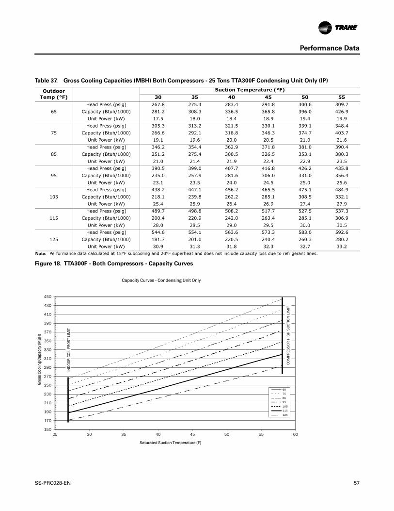
Performance Data
Table 37. Gross Cooling Capacities (MBH) Both Compressors - 25 Tons TTA300F Condensing Unit Only (IP)
Outdoor Temp (°F)
Suction Temperature (°F)30 35 40 45 50 55
65Head Press (psig) 267.8 275.4 283.4 291.8 300.6 309.7
Capacity (Btuh/1000) 281.2 308.3 336.5 365.8 396.0 426.9Unit Power (kW) 17.5 18.0 18.4 18.9 19.4 19.9
75Head Press (psig) 305.3 313.2 321.5 330.1 339.1 348.4
Capacity (Btuh/1000) 266.6 292.1 318.8 346.3 374.7 403.7Unit Power (kW) 19.1 19.6 20.0 20.5 21.0 21.6
85Head Press (psig) 346.2 354.4 362.9 371.8 381.0 390.4
Capacity (Btuh/1000) 251.2 275.4 300.5 326.5 353.1 380.3Unit Power (kW) 21.0 21.4 21.9 22.4 22.9 23.5
95Head Press (psig) 390.5 399.0 407.7 416.8 426.2 435.8
Capacity (Btuh/1000) 235.0 257.9 281.6 306.0 331.0 356.4Unit Power (kW) 23.1 23.5 24.0 24.5 25.0 25.6
105Head Press (psig) 438.2 447.1 456.2 465.5 475.1 484.9
Capacity (Btuh/1000) 218.1 239.8 262.2 285.1 308.5 332.1Unit Power (kW) 25.4 25.9 26.4 26.9 27.4 27.9
115Head Press (psig) 489.7 498.8 508.2 517.7 527.5 537.3
Capacity (Btuh/1000) 200.4 220.9 242.0 263.4 285.1 306.9Unit Power (kW) 28.0 28.5 29.0 29.5 30.0 30.5
125Head Press (psig) 544.6 554.1 563.6 573.3 583.0 592.6
Capacity (Btuh/1000) 181.7 201.0 220.5 240.4 260.3 280.2Unit Power (kW) 30.9 31.3 31.8 32.3 32.7 33.2
Note: Performance data calculated at 15°F subcooling and 20°F superheat and does not include capacity loss due to refrigerant lines.
Figure 18. TTA300F - Both Compressors - Capacity Curves
150
170
190
210
230
250
270
290
310
330
350
370
390
410
430
450
25 30 35 40 45 50 55 60
Gro
ss C
oolin
g Ca
paci
ty (M
BH
)
Saturated Suction Temperature (F)
Capacity Curves - Condensing Unit Only
65
75
85
95
105
115
125
IND
OO
R C
OIL
FR
OST
LIM
IT
COM
PRES
SOR
HIG
H S
UCT
ION
LIM
IT
SS-PRC028-EN 57

Performance Data
Table 38. Evaporator Fan Performance —TWE061 — Standard Air Handler
External Static Pressure (Inches of Water Gauge)
CFM.10" .20" .30" .40" .50" .60" .70" .80" .90" 1.00"
RPM BHP RPM BHP RPM BHP RPM BHP RPM BHP RPM BHP RPM BHP RPM BHP RPM BHP RPM BHP3/4 HP Standard Motor
1600 — — 738 0.33 790 0.38 840 0.44 888 0.50 936 0.56 980 0.62 1025 0.69 1070 0.76 1111 0.831700 719 0.33 771 0.38 821 0.44 869 0.50 914 0.56 959 0.62 1003 0.68 1047 0.75 1089 0.82 1129 0.901800 756 0.39 804 0.44 853 0.50 898 0.56 942 0.62 985 0.69 1028 0.75 1068 0.82 1109 0.89 1149 0.971900 792 0.45 838 0.51 884 0.57 928 0.63 971 0.69 1012 0.76 1052 0.83 1092 0.90 1131 0.97 1170 1.052000 829 0.52 873 0.58 917 0.64 959 0.71 1000 0.77 1040 0.84 1079 0.91 1117 0.98 1155 1.06 1192 1.142100 866 0.60 908 0.66 950 0.72 991 0.79 1030 0.86 1069 0.93 1106 1.00 1144 1.08 1179 1.15 1215 1.232200 903 0.68 944 0.74 983 0.81 1023 0.88 1061 0.95 1099 1.02 1134 1.10 1170 1.18 1206 1.26 1241 1.342300 940 0.78 979 0.84 1017 0.90 1055 0.97 1093 1.05 1129 1.13 1164 1.21 1198 1.28 1232 1.37 1266 1.452400 978 0.88 1015 0.94 1052 1.01 1089 1.08 1125 1.16 1160 1.24 1194 1.32 1227 1.40 1259 1.48 1292 1.57
1.5 HP High Static Motor
CFM
External Static Pressure (Inches of Water Gauge)
1.10" 1.20" 1.30" 1.40"RPM BHP RPM BHP RPM BHP RPM BHP
1.5 HP High Static Motor1600 1152 0.91 1191 0.99 1229 1.07 1264 1.141700 1170 0.98 1208 1.06 1246 1.14 1281 1.221800 1187 1.05 1226 1.13 1263 1.22 1300 1.301900 1207 1.13 1245 1.21 1281 1.30 1317 1.392000 1227 1.21 1265 1.30 1300 1.39 1335 1.482100 1250 1.31 1285 1.39 1319 1.48 — —2200 1274 1.42 1308 1.50 — — — —2300 1299 1.53 — — — — — —2400 — — — — — — — —
Notes:
1. Data includes pressure drop due to wet coil and 1" filter. 2. Fan motor heat (MBh) = 3.15 x BHP. 3. Trane’s factory supplied motors, in commercial equipment, are definite purpose motors, specifically designed and tested to operate reliably and
continuously at all cataloged conditions. Using the full horsepower range of our fan motors as shown in our tabular data will not result in nuisance tripping or premature motor failure. Our product’s warranty will not be affected.
4. For TWE061 Standard Motor use Table 51, p. 72, for High Static Motor use Table 52, p. 73.
58 SS-PRC028-EN

Performance Data
Table 39. Evaporator Fan Performance —TWE090 — Standard Air Handler
External Static Pressure (Inches of Water Gauge).10" .20" .30" .40" .50" .60" .70" .80" .90" 1.00"
CFM RPM BHP RPM BHP RPM BHP RPM BHP RPM BHP RPM BHP RPM BHP RPM BHP RPM BHP RPM BHP1.5 HP Standard Motor 2 HP High Static Motor
2400 — — 572 0.52 634 0.62 691 0.74 744 0.85 795 0.96 844 1.08 892 1.21 939 1.35 982 1.492550 — — 592 0.59 652 0.70 707 0.82 759 0.95 809 1.06 856 1.18 902 1.31 947 1.45 990 1.592700 — — 612 0.67 670 0.79 724 0.91 774 1.05 822 1.18 868 1.29 913 1.42 957 1.56 999 1.712850 575 0.68 633 0.73 689 0.89 741 1.01 790 1.15 837 1.29 882 1.42 925 1.55 967 1.68 1008 1.833000 599 0.76 654 0.82 709 0.99 760 1.13 807 1.26 853 1.41 896 1.56 939 1.69 980 1.82 1020 1.973150 623 0.85 675 0.93 729 1.11 778 1.25 825 1.39 869 1.54 911 1.70 953 1.85 992 1.98 1031 2.123300 647 0.95 697 1.09 749 1.22 797 1.38 842 1.52 886 1.67 927 1.83 967 2.00 1007 2.15 1045 2.303450 673 1.08 724 1.26 770 1.32 816 1.52 861 1.67 903 1.82 943 1.98 983 2.16 1020 2.33 1058 2.483600 698 1.21 746 1.43 790 1.43 836 1.67 880 1.83 922 1.98 961 2.14 999 2.32 1037 2.51 1073 2.68
3 HP Ultra High Static MotorExternal Static Pressure (Inches of Water Gauge)
1.10" 1.20" 1.30" 1.40" 1.50" 1.60" 1.70" 1.80" 1.90 2.00CFM RPM BHP RPM BHP RPM BHP RPM BHP RPM BHP RPM BHP RPM BHP RPM BHP RPM BHP RPM BHP
2 HP High Static Motor 3 HP Ultra High Static Motor2400 1023 1.62 1062 1.75 1101 1.89 1137 2.03 1172 2.16 1207 2.30 1241 2.44 1273 2.58 1303 2.71 1334 2.852550 1032 1.74 1071 1.88 1109 2.03 1145 2.17 1181 2.32 1215 2.46 1248 2.61 1281 2.75 1311 2.89 1341 3.042700 1040 1.86 1079 2.01 1117 2.17 1154 2.32 1189 2.47 1223 2.62 1255 2.77 1288 2.93 — — — —2850 1048 1.99 1087 2.14 1126 2.31 1161 2.47 1198 2.63 1232 2.79 1264 2.95 — — — — — —3000 1058 2.12 1096 2.29 1135 2.46 1171 2.63 1206 2.80 1239 2.96 — — — — — — — —3150 1069 2.27 1105 2.43 1142 2.60 1179 2.79 1214 2.96 — — — — — — — — — —3300 1082 2.45 1118 2.61 1154 2.78 1187 2.95 — — — — — — — — — — — —3450 1094 2.63 1130 2.79 1164 2.96 — — — — — — — — — — — — — —3600 1107 2.84 1144 3.00 — — — — — — — — — — — — — — — —
Notes:
1. Data includes pressure drop due to wet coil and 1" filter. 2. Fan motor heat (MBh) = 3.15 x BHP. 3. Trane’s factory supplied motors, in commercial equipment, are definite purpose motors, specifically designed and tested to operate reliably and
continuously at all cataloged conditions. Using the full horsepower range of our fan motors as shown in our tabular data will not result in nuisance tripping or premature motor failure. Our product’s warranty will not be affected.
4. For TWE090 Standard Motor use Table 51, p. 72, for High Static Motor use Table 52, p. 73, for Ultra High Static Motor use Table 53, p. 74.
SS-PRC028-EN 59
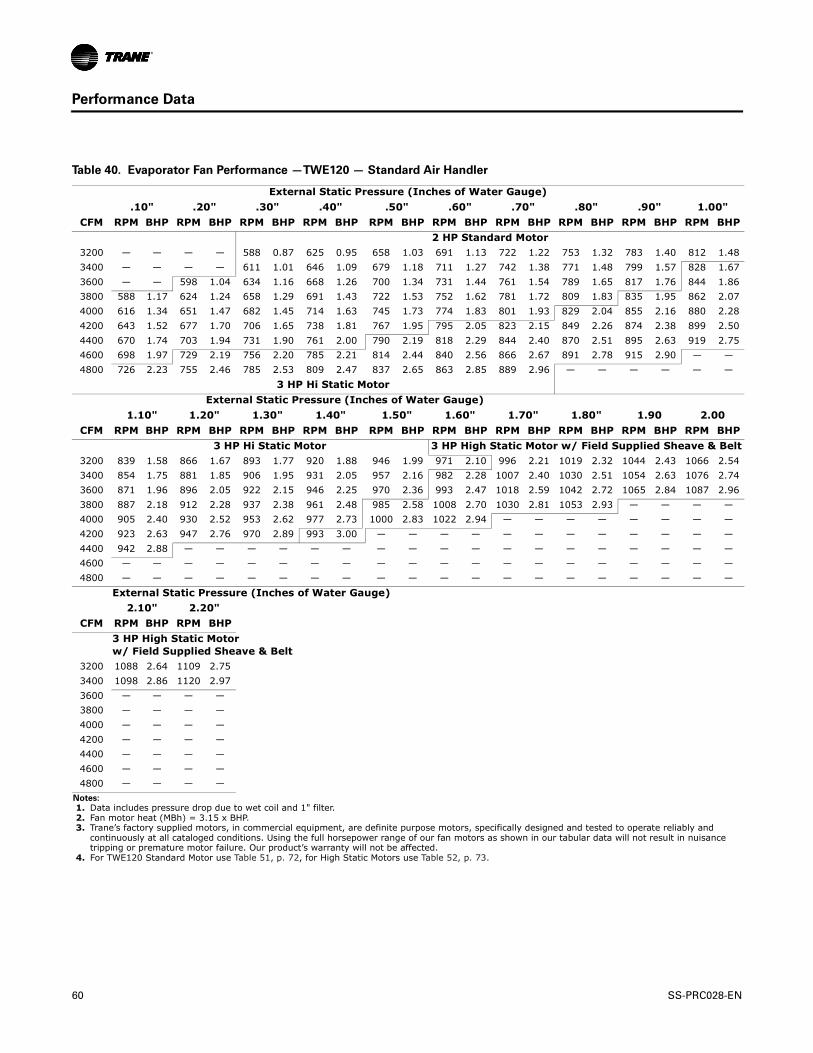
Performance Data
Table 40. Evaporator Fan Performance —TWE120 — Standard Air Handler
External Static Pressure (Inches of Water Gauge).10" .20" .30" .40" .50" .60" .70" .80" .90" 1.00"
CFM RPM BHP RPM BHP RPM BHP RPM BHP RPM BHP RPM BHP RPM BHP RPM BHP RPM BHP RPM BHP2 HP Standard Motor
3200 — — — — 588 0.87 625 0.95 658 1.03 691 1.13 722 1.22 753 1.32 783 1.40 812 1.483400 — — — — 611 1.01 646 1.09 679 1.18 711 1.27 742 1.38 771 1.48 799 1.57 828 1.673600 — — 598 1.04 634 1.16 668 1.26 700 1.34 731 1.44 761 1.54 789 1.65 817 1.76 844 1.863800 588 1.17 624 1.24 658 1.29 691 1.43 722 1.53 752 1.62 781 1.72 809 1.83 835 1.95 862 2.074000 616 1.34 651 1.47 682 1.45 714 1.63 745 1.73 774 1.83 801 1.93 829 2.04 855 2.16 880 2.284200 643 1.52 677 1.70 706 1.65 738 1.81 767 1.95 795 2.05 823 2.15 849 2.26 874 2.38 899 2.504400 670 1.74 703 1.94 731 1.90 761 2.00 790 2.19 818 2.29 844 2.40 870 2.51 895 2.63 919 2.754600 698 1.97 729 2.19 756 2.20 785 2.21 814 2.44 840 2.56 866 2.67 891 2.78 915 2.90 — —4800 726 2.23 755 2.46 785 2.53 809 2.47 837 2.65 863 2.85 889 2.96 — — — — — —
3 HP Hi Static MotorExternal Static Pressure (Inches of Water Gauge)
1.10" 1.20" 1.30" 1.40" 1.50" 1.60" 1.70" 1.80" 1.90 2.00CFM RPM BHP RPM BHP RPM BHP RPM BHP RPM BHP RPM BHP RPM BHP RPM BHP RPM BHP RPM BHP
3 HP Hi Static Motor 3 HP High Static Motor w/ Field Supplied Sheave & Belt3200 839 1.58 866 1.67 893 1.77 920 1.88 946 1.99 971 2.10 996 2.21 1019 2.32 1044 2.43 1066 2.543400 854 1.75 881 1.85 906 1.95 931 2.05 957 2.16 982 2.28 1007 2.40 1030 2.51 1054 2.63 1076 2.743600 871 1.96 896 2.05 922 2.15 946 2.25 970 2.36 993 2.47 1018 2.59 1042 2.72 1065 2.84 1087 2.963800 887 2.18 912 2.28 937 2.38 961 2.48 985 2.58 1008 2.70 1030 2.81 1053 2.93 — — — —4000 905 2.40 930 2.52 953 2.62 977 2.73 1000 2.83 1022 2.94 — — — — — — — —4200 923 2.63 947 2.76 970 2.89 993 3.00 — — — — — — — — — — — —4400 942 2.88 — — — — — — — — — — — — — — — — — —4600 — — — — — — — — — — — — — — — — — — — —4800 — — — — — — — — — — — — — — — — — — — —
CFM
External Static Pressure (Inches of Water Gauge)2.10" 2.20"
RPM BHP RPM BHP3 HP High Static Motor w/ Field Supplied Sheave & Belt
3200 1088 2.64 1109 2.753400 1098 2.86 1120 2.973600 — — — —3800 — — — —4000 — — — —4200 — — — —4400 — — — —4600 — — — —4800 — — — —
Notes:
1. Data includes pressure drop due to wet coil and 1" filter. 2. Fan motor heat (MBh) = 3.15 x BHP. 3. Trane’s factory supplied motors, in commercial equipment, are definite purpose motors, specifically designed and tested to operate reliably and
continuously at all cataloged conditions. Using the full horsepower range of our fan motors as shown in our tabular data will not result in nuisance tripping or premature motor failure. Our product’s warranty will not be affected.
4. For TWE120 Standard Motor use Table 51, p. 72, for High Static Motors use Table 52, p. 73.
60 SS-PRC028-EN

Performance Data
Table 4
1.
Evap
ora
tor
Fa
n P
erf
orm
an
ce -
TW
E12
0**
**
(4.)
- 2
-Sp
eed
VFD
, S
ZV
AV
Air
Ha
nd
ler
CFM
.10
.20
.30
.40
.50
.60
.70
.80
.90
1.0
0R
PM
HZ
BH
PR
PM
HZ
BH
PR
PM
HZ
BH
PR
PM
HZ
BH
PR
PM
HZ
BH
PR
PM
HZ
BH
PR
PM
HZ
BH
PR
PM
HZ
BH
PR
PM
HZ
BH
PR
PM
HZ
BH
P2
HP
Sta
nd
ard
Dri
ve32
0058
838
0.87
625
410.
9565
843
1.03
691
451.
1372
247
1.22
753
491.
3278
351
1.40
812
531.
4834
0061
140
1.01
646
421.
0967
944
1.18
711
471.
2774
249
1.38
771
501.
4879
952
1.57
828
441.
6736
0059
839
1.04
634
411.
1666
844
1.26
700
461.
3473
148
1.44
761
501.
5478
952
1.65
817
531.
7684
445
1.86
3800
588
381.
1762
441
1.24
658
431.
2969
145
1.43
722
471.
5375
249
1.62
781
511.
7280
953
1.83
835
441.
9586
246
2.07
4000
616
401.
3465
143
1.47
682
451.
4571
447
1.63
745
491.
7377
451
1.83
801
521.
9382
944
2.04
855
452.
1688
047
2.28
4200
643
421.
5267
744
1.70
706
461.
6573
848
1.81
767
501.
9579
542
2.05
823
442.
1584
945
2.26
874
462.
3889
948
2.50
4400
670
441.
7470
346
1.94
731
481.
9076
150
2.00
790
422.
1981
843
2.29
844
452.
4087
046
2.51
895
472.
6391
949
2.75
4600
698
461.
9772
939
2.19
756
402.
2078
542
2.21
814
432.
4484
044
2.56
866
462.
6789
147
2.78
915
482.
9048
0072
638
2.23
755
402.
4678
542
2.53
809
432.
4783
744
2.65
863
462.
8588
947
2.96
3 H
P H
igh
Sta
tic
Dri
veE
xter
nal
Sta
tic
Pre
ssu
re (
Inch
es o
f W
ater
Gau
ge)
CFM
1.1
01
.20
1.3
01
.40
1.5
01
.60
1.7
01
.80
1.9
02
.00
RP
MH
ZB
HP
RP
MH
ZB
HP
RP
MH
ZB
HP
RP
MH
ZB
HP
RP
MH
ZB
HP
RP
MH
ZB
HP
RP
MH
ZB
HP
RP
MH
ZB
HP
RP
MH
ZB
HP
RP
MH
ZB
HP
3 H
P H
igh
Sta
tic
Dri
ve32
0083
944
1.58
866
461.
6789
347
1.77
920
491.
8894
650
1.99
971
512.
1099
653
2.21
1019
542.
3210
4455
2.43
1066
562.
5434
0085
445
1.75
881
471.
8590
648
1.95
931
492.
0595
751
2.16
982
522.
2810
0753
2.40
1030
542.
5110
5456
2.63
1076
572.
7436
0087
146
1.96
896
472.
0592
249
2.15
946
502.
2597
051
2.36
993
532.
4710
1854
2.59
1042
552.
7210
6556
2.84
1087
582.
9638
0088
747
2.18
912
482.
2893
750
2.38
961
512.
4898
552
2.58
1008
532.
7010
3054
2.81
1053
562.
9340
0090
548
2.40
930
492.
5295
350
2.62
977
522.
7310
0053
2.83
1022
542.
9442
0092
349
2.63
947
502.
7697
051
2.89
993
533.
0044
0094
250
2.88
4600
4800
Ext
ern
al S
tati
c P
ress
ure
(In
ches
of
Wat
er G
aug
e)
CFM
2.1
02
.20
RP
MH
ZB
HP
RP
MH
ZB
HP
3 H
P H
igh
Sta
tic
Dri
ve32
0010
8858
2.64
1109
592.
7534
0010
9858
2.86
1120
592.
97
3600
3800
4000
4200
4400
4600
4800
No
tes:
1.
Gra
y ar
ea d
enot
es d
isal
low
ed f
or S
ingl
e Zo
ne V
AV S
tatic
Pre
ssur
e Con
trol
Poi
nt.
2.
Hz
data
is V
aria
ble
Freq
uenc
y D
rive
fre
quen
cy.
3.
Sin
gle
Zone
VAV
Sta
tic P
ress
ure
Con
trol
Poi
nt o
pera
tion
disa
llow
ed a
t le
ss t
han
340
CFM
/ton
. 4
.TW
E120
D30
3, T
WE1
20D
304,
TW
E120
D3R
3, T
WE1
20D
3R4,
TW
E120
D40
3, T
WE1
20D
404,
TW
E120
D4R
3, T
WE1
20D
4R4,
TW
E120
DW
03,
TWE1
20D
W04
, TW
E120
DW
R3,
TW
E120
DW
R4,
TW
E120
E303
, TW
E120
E304
, TW
E120
E3R3,
TW
E120
E3R4,
TW
E120
E403
, TW
E120
E404
, TW
E120
E4R3,
TW
E120
E4R4,
TW
E120
EW03
, TW
E120
EW04
, TW
E120
EWR3,
TW
E120
EWR4
SS-PRC028-EN 61

Performance Data
Table 42. Evaporator Fan Performance —TWE150 — Standard Air Handler
External Static Pressure (Inches of Water Gauge)
CFM.10" .20" .30" .40" .50" .60" .70" .80" .90" 1.00"
RPM BHP RPM BHP RPM BHP RPM BHP RPM BHP RPM BHP RPM BHP RPM BHP RPM BHP RPM BHP2 HP Standard Motor 2 HP Standard Motor w/ Field Supplied Sheave & Belt
4000 — — — — — — 614 0.85 658 0.98 698 1.12 728 1.22 756 1.32 786 1.43 817 1.564200 — — — — 581 0.80 627 0.93 669 1.05 710 1.21 744 1.34 772 1.44 799 1.55 827 1.664400 — — — — 595 0.88 640 1.02 682 1.15 722 1.29 758 1.45 789 1.58 814 1.68 840 1.794600 — — 563 0.82 609 0.96 653 1.11 695 1.25 732 1.38 771 1.55 804 1.71 831 1.83 856 1.944800 — — 579 0.90 624 1.05 667 1.20 707 1.35 745 1.50 783 1.66 817 1.83 847 1.98 872 2.105000 — — 595 0.99 639 1.15 681 1.31 721 1.47 759 1.62 794 1.77 828 1.94 861 2.12 888 2.275200 568 0.95 612 1.09 655 1.25 695 1.42 735 1.58 771 1.74 806 1.90 840 2.06 873 2.25 903 2.435400 587 1.05 628 1.20 670 1.36 710 1.53 748 1.71 784 1.88 819 2.04 852 2.20 885 2.38 915 2.585600 605 1.16 645 1.31 686 1.48 724 1.66 762 1.83 798 2.01 832 2.19 864 2.35 896 2.52 928 2.735800 624 1.28 662 1.43 702 1.60 740 1.79 777 1.97 812 2.15 845 2.34 877 2.51 908 2.68 938 2.876000 643 1.40 679 1.56 719 1.74 755 1.92 791 2.12 826 2.30 858 2.49 891 2.68 920 2.86 950 3.03
3 HP High Static MotorExternal Static Pressure (Inches of Water Gauge)
CFM1.10" 1.20" 1.30" 1.40" 1.50" 1.60" 1.70" 1.80" 1.90 2.00
RPM BHP RPM BHP RPM BHP RPM BHP RPM BHP RPM BHP RPM BHP RPM BHP RPM BHP RPM BHP2 HP Standard Motor w/ Field Supplied Sheave & Belt 3 HP High Static Motor
4000 849 1.70 882 1.85 915 2.02 947 2.19 976 2.36 1002 2.52 1028 2.69 1053 2.86 1078 3.03 1101 3.204200 858 1.80 888 1.95 919 2.11 950 2.28 980 2.45 1010 2.64 1036 2.81 1061 2.98 1085 3.15 1109 3.334400 867 1.92 896 2.06 925 2.21 955 2.38 985 2.55 1013 2.73 1044 2.93 1070 3.11 1094 3.30 1117 3.474600 880 2.05 906 2.19 934 2.33 961 2.49 989 2.66 1018 2.84 1045 3.02 1074 3.22 1101 3.43 1125 3.614800 896 2.22 918 2.33 944 2.47 970 2.63 996 2.79 1023 2.96 1051 3.15 1078 3.34 1105 3.55 1131 3.745000 911 2.39 934 2.51 956 2.64 980 2.78 1005 2.93 1031 3.11 1057 3.28 1083 3.48 1109 3.67 1135 3.875200 927 2.57 950 2.71 972 2.83 993 2.95 1016 3.11 1040 3.27 1064 3.43 1090 3.62 1115 3.82 1139 4.015400 943 2.76 966 2.90 989 3.04 1008 3.17 1029 3.30 1051 3.45 1075 3.62 1098 3.79 1122 3.98 1146 4.175600 956 2.92 982 3.11 1004 3.25 1025 3.39 1045 3.52 1065 3.66 1085 3.81 1108 3.98 1130 4.16 1153 4.355800 969 3.09 996 3.29 1020 3.47 1041 3.62 1062 3.77 1081 3.91 1099 4.04 1120 4.20 1141 4.37 1162 4.556000 980 3.25 1008 3.46 1034 3.67 1057 3.86 1077 4.01 1097 4.16 1115 4.30 1134 4.45 1153 4.60 1174 4.78
5 HP Ultra High Static Motor
CFM
External Static Pressure (Inches of Water Gauge)2.10" 2.20" 2.30” 2.40”
RPM BHP RPM BHP RPM BHP RPM BHP5 HP Ultra High Static Motor
4000 1126 3.38 1148 3.54 1170 3.73 1191 3.894200 1132 3.51 1155 3.69 1179 3.88 1200 4.064400 1141 3.66 1163 3.84 1186 4.03 1208 4.234600 1150 3.81 1172 4.00 1193 4.18 1215 4.374800 1157 3.96 1179 4.15 1202 4.36 — —5000 1161 4.09 1186 4.30 1210 4.52 — —5200 1164 4.21 1189 4.44 1214 4.66 — —5400 1170 4.38 1193 4.58 1218 4.81 — —5600 1176 4.55 1198 4.74 1222 4.97 — —5800 1184 4.74 1206 4.94 — — — —6000 1194 4.96 — — — — — —
Notes:
1. Data includes pressure drop due to wet coil and 1" filter. 2. Fan motor heat (MBh) = 3.15 x BHP. 3. Trane’s factory supplied motors, in commercial equipment, are definite purpose motors, specifically designed and tested to operate reliably and
continuously at all cataloged conditions. Using the full horsepower range of our fan motors as shown in our tabular data will not result in nuisance tripping or premature motor failure. Our product’s warranty will not be affected.
4. For TWE150 Standard Motor use Table 51, p. 72, for High Static Motor use Table 52, p. 73, for Ultra High Static Motor (3 HP) use Table 53, p. 74.
62 SS-PRC028-EN

Performance Data
Table 4
3.
E
va
po
rato
r Fan
Perf
orm
an
ce
- T
WE
15
0*
***
(4.)
- 2
-Sp
ee
d V
FD
, S
ZV
AV
Air
Han
dle
r
CFM
.10
.20
.30
.40
.50
.60
.70
.80
.90
1.0
0R
PM
HZ
BH
PR
PM
HZ
BH
PR
PM
HZ
BH
PR
PM
HZ
BH
PR
PM
HZ
BH
PR
PM
HZ
BH
PR
PM
HZ
BH
PR
PM
HZ
BH
PR
PM
HZ
BH
PR
PM
HZ
BH
P2
HP
Sta
nd
ard
Dri
ve40
0061
440
0.85
658
430.
9869
846
1.12
728
481.
2275
649
1.32
786
511.
4381
753
1.56
4200
581
380.
8062
741
0.93
669
441.
0571
046
1.21
744
491.
3477
251
1.44
799
521.
5582
754
1.66
4400
595
390.
8864
042
1.02
682
451.
1572
247
1.29
758
501.
4578
952
1.58
814
531.
6884
055
1.79
4600
609
400.
9665
343
1.11
695
451.
2573
248
1.38
771
501.
5580
453
1.71
831
541.
8385
656
1.94
4800
579
380.
9062
441
1.05
667
441.
2070
746
1.35
745
491.
5078
351
1.66
817
531.
8384
755
1.98
872
572.
1050
0059
539
0.99
639
421.
1568
145
1.31
721
471.
4775
950
1.62
794
521.
7782
854
1.94
861
562.
1288
845
2.27
5200
612
401.
0965
543
1.25
695
451.
4273
548
1.58
771
501.
7480
653
1.90
840
552.
0687
344
2.25
903
452.
4354
0058
738
1.05
628
411.
2067
044
1.36
710
461.
5374
849
1.71
784
511.
8881
954
2.04
852
432.
2088
545
2.38
915
462.
5856
0060
540
1.16
645
421.
3168
645
1.48
724
471.
6676
250
1.83
798
522.
0183
242
2.19
864
442.
3589
645
2.52
928
472.
7358
0062
441
1.28
662
431.
4370
246
1.60
740
481.
7977
751
1.97
812
532.
1584
543
2.34
877
442.
5190
846
2.68
938
472.
8760
0064
342
1.40
679
441.
5671
947
1.74
755
491.
9279
152
2.12
826
422.
3085
843
2.49
891
452.
6892
046
2.86
950
483.
03
5 H
P H
igh
Sta
tic
Dri
veE
xter
nal
Sta
tic
Pre
ssu
re (
Inch
es o
f W
ater
Gau
ge)
CFM
1.1
01
.20
1.3
01
.40
1.5
01
.60
1.7
01
.80
1.9
02
.00
RP
MH
ZB
HP
RP
MH
ZB
HP
RP
MH
ZB
HP
RP
MH
ZB
HP
RP
MH
ZB
HP
RP
MH
ZB
HP
RP
MH
ZB
HP
RP
MH
ZB
HP
RP
MH
ZB
HP
RP
MH
ZB
HP
5 H
P H
igh
Sta
tic
Dri
ve40
0084
943
1.70
882
441.
8591
546
2.02
947
482.
1997
649
2.36
1002
502.
5210
2852
2.69
1053
532.
8610
7854
3.03
1101
553.
2042
0085
843
1.80
888
451.
9591
946
2.11
950
482.
2898
049
2.45
1010
512.
6410
3652
2.81
1061
532.
9810
8555
3.15
1109
563.
3344
0086
744
1.92
896
452.
0692
547
2.21
955
482.
3898
550
2.55
1013
512.
7310
4453
2.93
1070
543.
1110
9455
3.30
1117
563.
4746
0088
044
2.05
906
462.
1993
447
2.33
961
482.
4998
950
2.66
1018
512.
8410
4553
3.02
1074
543.
2211
0155
3.43
1125
573.
6148
0089
645
2.22
918
462.
3394
448
2.47
970
492.
6399
650
2.79
1023
522.
9610
5153
3.15
1078
543.
3411
0556
3.55
1131
573.
7450
0091
146
2.39
934
472.
5195
648
2.64
980
492.
7810
0551
2.93
1031
523.
1110
5753
3.28
1083
553.
4811
0956
3.67
1135
573.
8752
0092
747
2.57
950
482.
7197
249
2.83
993
502.
9510
1651
3.11
1040
523.
2710
6454
3.43
1090
553.
6211
1556
3.82
1139
574.
0154
0094
348
2.76
966
492.
9098
950
3.04
1008
513.
1710
2952
3.30
1051
533.
4510
7554
3.62
1098
553.
7911
2257
3.98
1146
584.
1756
0095
648
2.92
982
493.
1110
0451
3.25
1025
523.
3910
4553
3.52
1065
543.
6610
8555
3.81
1108
563.
9811
3057
4.16
1153
584.
3558
0096
949
3.09
996
503.
2910
2051
3.47
1041
523.
6210
6254
3.77
1081
543.
9110
9955
4.04
1120
564.
2011
4157
4.37
1162
594.
5560
0098
049
3.25
1008
513.
4610
3452
3.67
1057
533.
8610
7754
4.01
1097
554.
1611
1556
4.30
1134
574.
4511
5358
4.60
1174
594.
78co
nti
nu
ed o
n n
ext
pag
e
Ext
ern
al S
tati
c P
ress
ure
(In
ches
of
Wat
er G
aug
e)
SS-PRC028-EN 63

Performance Data
CFM2
.10
2.2
02
.30
2.4
0R
PM
HZ
BH
PR
PM
HZ
BH
PR
PM
HZ
BH
PR
PM
HZ
BH
P5
HP
Hig
h S
tati
c D
rive
4000
1126
573.
3811
4858
3.54
1170
593.
7311
9160
3.89
4200
1132
573.
5111
5558
3.69
1179
593.
8812
0060
4.06
4400
1141
573.
6611
6359
3.84
1186
604.
03
4600
1150
583.
8111
7259
4.00
1193
604.
1848
0011
5758
3.96
1179
594.
15
5000
1161
584.
0911
8660
4.30
5200
1164
594.
2111
8960
4.44
5400
1170
594.
3811
9360
4.58
5600
1176
594.
5511
9860
4.74
5800
1184
604.
7460
0011
9460
4.96
No
tes:
1.
Gra
y ar
ea d
enot
es d
isal
low
ed f
or S
ingl
e Zo
ne V
AV S
tatic
Pre
ssur
e Con
trol
Poi
nt.
2.
Hz
data
is V
aria
ble
Freq
uenc
y D
rive
fre
quen
cy.
3.
Sin
gle
Zone
VAV
Sta
tic P
ress
ure
Con
trol
Poi
nt o
pera
tion
disa
llow
ed a
t le
ss t
han
340
CFM
/ton
. 4
.TW
E150
E303
, TW
E150
E304
, TW
E150
E3R3,
TW
E150
E3R4,
TW
E150
E403
, TW
E150
E404
, TW
E150
E4R3,
TW
E150
E4R4,
TW
E150
EW03
, TW
E150
EW04
, TW
E150
EWR3,
TW
E150
EWR4
Tab
le 4
3.
(co
nti
nu
ed
) E
va
po
rato
r Fa
n P
erf
orm
an
ce
- T
WE
150
***
*(4
.) - 2
-Sp
ee
d V
FD
, S
ZV
AV
Air
Ha
nd
ler
64 SS-PRC028-EN

Performance Data
Table 44. Evaporator Fan Performance —TWE180 — Standard Air Handler
External Static Pressure (Inches of Water Gauge)
CFM.10" .20" .30" .40" .50" .60" .70" .80" .90" 1.00"
RPM BHP RPM BHP RPM BHP RPM BHP RPM BHP RPM BHP RPM BHP RPM BHP RPM BHP RPM BHP3 HP Standard Motor w/ Field Supplied Sheave & Belt 3 HP Standard Motor
4800 492 0.80 539 0.94 583 1.08 624 1.21 663 1.34 701 1.49 738 1.66 774 1.82 807 1.98 839 2.145100 517 0.95 562 1.08 604 1.24 644 1.38 681 1.52 718 1.67 753 1.83 788 2.00 821 2.18 853 2.355400 542 1.11 585 1.25 625 1.41 663 1.57 700 1.71 735 1.86 769 2.02 802 2.20 835 2.38 866 2.575700 567 1.29 609 1.43 647 1.60 684 1.78 719 1.93 753 2.08 786 2.24 818 2.41 849 2.60 881 2.806000 593 1.48 632 1.64 669 1.80 705 1.99 739 2.16 773 2.32 804 2.48 835 2.66 865 2.84 895 3.046300 619 1.70 656 1.86 692 2.03 726 2.22 760 2.42 792 2.59 823 2.75 853 2.93 882 3.12 910 3.316600 644 1.94 681 2.11 715 2.28 748 2.48 781 2.69 811 2.87 841 3.04 871 3.22 899 3.40 927 3.606900 670 2.20 705 2.37 739 2.55 771 2.75 802 2.97 832 3.18 861 3.36 890 3.54 917 3.72 944 3.927200 696 2.49 730 2.66 763 2.85 794 3.05 824 3.27 853 3.49 881 3.70 909 3.89 936 4.08 963 4.28
5 HP High Static MotorExternal Static Pressure (Inches of Water Gauge)
CFM1.10" 1.20" 1.30" 1.40" 1.50" 1.60" 1.70" 1.80" 1.90 2.00
RPM BHP RPM BHP RPM BHP RPM BHP RPM BHP RPM BHP RPM BHP RPM BHP RPM BHP RPM BHP5 HP High Static Motor 5 HP High Static Motor w/ Field Supplied Sheave & Belt
4800 869 2.30 897 2.46 926 2.62 953 2.77 979 2.93 1004 3.08 1029 3.24 1051 3.38 1075 3.54 1097 3.695100 883 2.52 911 2.69 940 2.86 965 3.02 992 3.19 1017 3.36 1042 3.52 1065 3.68 1088 3.84 1111 4.025400 897 2.75 925 2.93 953 3.11 980 3.29 1005 3.47 1031 3.65 1055 3.82 1078 3.99 1102 4.17 1123 4.345700 910 2.99 940 3.19 966 3.38 993 3.57 1019 3.75 1044 3.94 1068 4.13 1092 4.32 1114 4.50 1137 4.696000 924 3.25 953 3.45 980 3.65 1008 3.86 1033 4.06 1057 4.26 1081 4.45 1105 4.66 1129 4.86 1150 5.056300 939 3.52 967 3.73 995 3.95 1022 4.17 1046 4.37 1071 4.59 1095 4.79 1119 5.01 — — — —6600 954 3.81 981 4.02 1009 4.25 1035 4.48 1061 4.71 1085 4.93 — — — — — — — —6900 971 4.13 998 4.35 1022 4.57 1049 4.81 1074 5.04 — — — — — — — — — —7200 988 4.48 1014 4.70 1039 4.93 1063 5.15 — — — — — — — — — — — —
CFM
External Static Pressure (Inches of Water Gauge)2.10" 2.20" 2.30” 2.40”
RPM BHP RPM BHP RPM BHP RPM BHP5 HP High Static Motor
w/ Field Supplied Sheave & Belt4800 1120 3.84 1141 3.99 1162 4.14 1183 4.305100 1132 4.17 1154 4.33 1175 4.49 1196 4.665400 1146 4.52 1167 4.69 1188 4.86 1209 5.045700 1159 4.87 1180 5.06 — — — —6000 — — — — — — — —6300 — — — — — — — —6600 — — — — — — — —6900 — — — — — — — —7200 — — — — — — — —
Notes:
1. Data includes pressure drop due to wet coil and 1" filter. 2. Fan motor heat (MBh) = 3.15 x BHP. 3. Trane’s factory supplied motors, in commercial equipment, are definite purpose motors, specifically designed and tested to operate reliably and
continuously at all cataloged conditions. Using the full horsepower range of our fan motors as shown in our tabular data will not result in nuisance tripping or premature motor failure. Our product’s warranty will not be affected.
4. For TWE180 Low Static Motor use Table 50, p. 71, for Standard Motor use Table 51, p. 72, for High Static Motor use Table 52, p. 73.
SS-PRC028-EN 65

Performance Data
Table 4
5.
E
va
po
rato
r Fan
Perf
orm
an
ce
- T
WE
180
***
*(4
.) -
2-S
pe
ed
VF
D, S
ZV
AV
Air
Ha
nd
ler
CFM
.10
.20
.30
.40
.50
.60
.70
.80
.90
1.0
0R
PM
HZ
BH
PR
PM
HZ
BH
PR
PM
HZ
BH
PR
PM
HZ
BH
PR
PM
HZ
BH
PR
PM
HZ
BH
PR
PM
HZ
BH
PR
PM
HZ
BH
PR
PM
HZ
BH
PR
PM
HZ
BH
P3
HP
Sta
nd
ard
Dri
ve48
0053
938
0.94
583
411.
0862
444
1.21
663
471.
3470
149
1.49
738
521.
6677
454
1.82
807
571.
9883
959
2.14
5100
562
391.
0860
442
1.24
644
451.
3868
148
1.52
718
501.
6775
353
1.83
788
552.
0082
158
2.18
853
602.
3554
0054
238
1.11
585
411.
2562
544
1.41
663
471.
5770
049
1.71
735
521.
8676
954
2.02
802
562.
2083
559
2.38
866
442.
5757
0056
740
1.29
609
431.
4364
745
1.60
684
481.
7871
951
1.93
753
532.
0878
655
2.24
818
572.
4184
960
2.60
881
442.
8060
0059
342
1.48
632
441.
6466
947
1.80
705
501.
9973
952
2.16
773
542.
3280
456
2.48
835
592.
6686
544
2.84
895
453.
0463
0061
943
1.70
656
461.
8669
249
2.03
726
512.
2276
053
2.42
792
562.
5982
358
2.75
853
602.
9388
244
3.12
910
463.
3166
0064
445
1.94
681
482.
1171
550
2.28
748
532.
4878
155
2.69
811
572.
8784
159
3.04
871
443.
2289
945
3.40
927
473.
6069
0067
047
2.20
705
502.
3773
952
2.55
771
542.
7580
256
2.97
832
423.
1886
143
3.36
890
453.
5491
746
3.72
944
483.
9272
0069
649
2.49
730
512.
6676
354
2.85
794
563.
0582
442
3.27
853
433.
4988
144
3.70
909
463.
8993
647
4.08
963
494.
285
HP
Hig
h S
tati
c D
rive
Ext
ern
al S
tati
c P
ress
ure
(In
ches
of
Wat
er G
aug
e)
CFM
1.1
01
.20
1.3
01
.40
1.5
01
.60
1.7
01
.80
1.9
02
.00
RP
MH
ZB
HP
RP
MH
ZB
HP
RP
MH
ZB
HP
RP
MH
ZB
HP
RP
MH
ZB
HP
RP
MH
ZB
HP
RP
MH
ZB
HP
RP
MH
ZB
HP
RP
MH
ZB
HP
RP
MH
ZB
HP
5 H
P H
igh
Sta
tic
Dri
ve48
0086
944
2.30
897
452.
4692
647
2.62
953
482.
7797
949
2.93
1004
513.
0810
2952
3.24
1051
533.
3810
7554
3.54
1097
553.
6951
0088
344
2.52
911
462.
6994
047
2.86
965
493.
0299
250
3.19
1017
513.
3610
4252
3.52
1065
543.
6810
8855
3.84
1111
564.
0254
0089
745
2.75
925
472.
9395
348
3.11
980
493.
2910
0551
3.47
1031
523.
6510
5553
3.82
1078
543.
9911
0256
4.17
1123
574.
3457
0091
046
2.99
940
473.
1996
649
3.38
993
503.
5710
1951
3.75
1044
533.
9410
6854
4.13
1092
554.
3211
1456
4.50
1137
574.
6960
0092
447
3.25
953
483.
4598
049
3.65
1008
513.
8610
3352
4.06
1057
534.
2610
8154
4.45
1105
564.
6611
2957
4.86
1150
585.
0563
0093
947
3.52
967
493.
7399
550
3.95
1022
514.
1710
4653
4.37
1071
544.
5910
9555
4.79
1119
565.
0166
0095
448
3.81
981
494.
0210
0951
4.25
1035
524.
4810
6153
4.71
1085
554.
9369
0097
149
4.13
998
504.
3510
2251
4.57
1049
534.
8110
7454
5.04
7200
988
504.
4810
1451
4.70
1039
524.
9310
6354
5.15
Ext
ern
al S
tati
c P
ress
ure
(In
ches
of
Wat
er G
aug
e)
CFM
2.1
02
.20
2.3
02
.40
RP
MH
ZB
HP
RP
MH
ZB
HP
RP
MH
ZB
HP
RP
MH
ZB
HP
5 H
P H
igh
Sta
tic
Dri
ve48
0011
2056
3.84
1141
573.
9911
6259
4.14
1183
604.
3051
0011
3257
4.17
1154
584.
3311
7559
4.49
1196
604.
6654
0011
4658
4.52
1167
594.
6911
8860
4.86
5700
1159
584.
8711
8059
5.06
6000
6300
6600
6900
7200
No
tes:
1.
Gra
y ar
ea d
enot
es d
isal
low
ed f
or S
ingl
e Zo
ne V
AV S
tatic
Pre
ssur
e Con
trol
Poi
nt.
2.
Hz
data
is V
aria
ble
Freq
uenc
y D
rive
fre
quen
cy.
3.
Sin
gle
Zone
VAV
Sta
tic P
ress
ure
Con
trol
Poi
nt o
pera
tion
disa
llow
ed a
t le
ss t
han
340
CFM
/ton
. 4
.TW
E180
E303
, TW
E180
E304
, TW
E180
E3R3,
TW
E180
E3R4,
TW
E180
E403
, TW
E180
E404
, TW
E180
E4R3,
TW
E180
E4R4,
TW
E180
EW03
, TW
E180
EW04
, TW
E180
EWR3,
TW
E180
EWR4
66 SS-PRC028-EN

Performance Data
Table 46. Evaporator Fan Performance — TWE240 — Standard Air Handler
External Static Pressure (Inches of Water Gauge)
CFM.10" .20" .30" .40" .50" .60" .70" .80" .90" 1.00"
RPM BHP RPM BHP RPM BHP RPM BHP RPM BHP RPM BHP RPM BHP RPM BHP RPM BHP RPM BHP3 HP Low Static Motor 5 HP Standard Motor
6400 — — — — 652 1.55 693 1.70 732 1.86 769 2.02 802 2.17 833 2.33 867 2.53 901 2.756800 — — — — 677 1.79 717 1.96 754 2.12 791 2.29 824 2.46 855 2.62 885 2.79 916 3.007200 — — 661 1.87 703 2.05 742 2.24 778 2.42 812 2.59 846 2.77 878 2.95 906 3.11 934 3.297600 647 1.98 688 2.15 729 2.34 766 2.55 802 2.74 835 2.92 868 3.10 900 3.29 929 3.48 956 3.668000 677 2.29 716 2.47 755 2.67 791 2.88 826 3.09 858 3.28 889 3.47 921 3.67 951 3.87 979 4.068400 707 2.63 744 2.82 781 3.02 817 3.24 851 3.46 883 3.68 913 3.87 942 4.07 972 4.28 1000 4.498800 737 3.01 773 3.21 808 3.41 843 3.63 876 3.87 907 4.10 937 4.31 965 4.52 994 4.73 1022 4.959200 767 3.41 802 3.63 836 3.84 869 4.06 901 4.30 932 4.55 961 4.79 989 5.00 1016 5.21 1044 5.449600 797 3.86 831 4.08 863 4.30 896 4.53 927 4.78 957 5.03 986 5.29 1013 5.52 1040 5.75 1065 5.97
7.5 HP Ultra Hi Static Motor 5 HP Hi Standard Motor w/ Field Supplied Sheaves
External Static Pressure (Inches of Water Gauge)
CFM1.10" 1.20" 1.30" 1.40" 1.50" 1.60" 1.70" 1.80" 1.90 2.00
RPM BHP RPM BHP RPM BHP RPM BHP RPM BHP RPM BHP RPM BHP RPM BHP RPM BHP RPM BHP5 HP Standard Motor 5 HP Standard Motor w/ Field Supplied Sheaves
6400 934 2.95 965 3.16 996 3.37 1028 3.58 1059 3.81 1091 4.03 1120 4.25 1148 4.46 1177 4.69 1204 4.906800 948 3.22 979 3.45 1008 3.66 1039 3.89 1069 4.12 1099 4.35 1128 4.58 1156 4.81 1185 5.05 1212 5.287200 964 3.51 994 3.75 1024 3.99 1052 4.22 1079 4.45 1108 4.69 1136 4.93 1166 5.19 1193 5.43 1219 5.677600 982 3.85 1011 4.07 1039 4.31 1066 4.56 1095 4.82 1121 5.06 1148 5.31 1174 5.56 1202 5.82 1228 6.078000 1004 4.25 1029 4.45 1055 4.67 1082 4.92 1109 5.19 1136 5.46 1161 5.71 1186 5.97 1213 6.24 1236 6.488400 1027 4.70 1051 4.90 1075 5.10 1100 5.33 1125 5.58 1151 5.85 1177 6.14 1202 6.42 1225 6.68 1250 6.968800 1049 5.17 1074 5.39 1097 5.59 1120 5.81 1144 6.03 1168 6.30 1192 6.57 1216 6.85 1241 7.16 1264 7.449200 1071 5.68 1096 5.90 1120 6.13 1143 6.34 1164 6.56 1186 6.79 1209 7.05 1233 7.35 — — — —9600 1092 6.21 1117 6.45 1142 6.69 1166 6.93 1187 7.15 1208 7.38 — — — — — — — —
7.5 HP Ultra High Static Motor 7.5 HP Ultra High Static Motor w/ Field Supplied Fan Sheave & Belt
CFM
External Static Pressure (Inches of Water Gauge)2.10" 2.20" 2.30” 2.40”
RPM BHP RPM BHP RPM BHP RPM BHP7.5 HP Ultra High Static Motor w/ Field Supplied
Fan Sheave & Belt6400 1230 5.11 1257 5.33 1282 5.54 1308 5.776800 1239 5.52 1265 5.75 1290 5.98 1315 6.207200 1246 5.92 1272 6.17 1298 6.41 1323 6.667600 1255 6.35 1282 6.61 1306 6.86 — —8000 1262 6.76 1289 7.04 1313 7.31 — —8400 1273 7.22 — — — — — —8800 — — — — — — — —9200 — — — — — — — —9600 — — — — — — — —
Notes:
1. Data includes pressure drop due to wet coil and 1" filter. 2. Fan motor heat (MBh) = 3.15 x BHP. 3. Trane’s factory supplied motors, in commercial equipment, are definite purpose motors, specifically designed and tested to operate reliably and
continuously at all cataloged conditions. Using the full horsepower range of our fan motors as shown in our tabular data will not result in nuisance tripping or premature motor failure. Our product’s warranty will not be affected.
4. For TWE240 Low Static Motor use Table 50, p. 71, for Standard Motor use Table 51, p. 72, for High Static Motors (5 HP and 7½ HP) use Table 52, p. 73.
SS-PRC028-EN 67
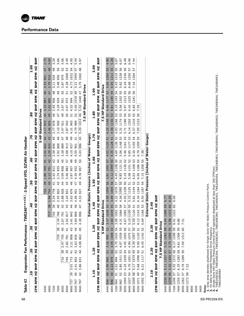
Performance Data
Table 4
7.
Eva
po
rato
r Fan
Perf
orm
an
ce
- T
WE
24
0*
***
(4.)
- 2
-Sp
ee
d V
FD
, S
ZV
AV
Air
Han
dle
r
CFM
.10
.20
.30
.40
.50
.60
.70
.80
.90
1.0
0R
PM
HZ
BH
PR
PM
HZ
BH
PR
PM
HZ
BH
PR
PM
HZ
BH
PR
PM
HZ
BH
PR
PM
HZ
BH
PR
PM
HZ
BH
PR
PM
HZ
BH
PR
PM
HZ
BH
PR
PM
HZ
BH
P5
HP
Sta
nd
ard
Dri
ve64
0073
239
1.86
769
412.
0280
242
2.17
833
442.
3386
746
2.53
901
472.
7568
0071
738
1.96
754
402.
1279
142
2.29
824
432.
4685
545
2.62
885
472.
7991
648
3.00
7200
742
392.
2477
841
2.42
812
432.
5984
645
2.77
878
462.
9590
648
3.11
934
493.
2976
0072
938
2.34
766
402.
5580
242
2.74
835
442.
9286
846
3.10
900
473.
2992
949
3.48
956
503.
6680
0071
638
2.47
755
402.
6779
142
2.88
826
443.
0985
845
3.28
889
473.
4792
149
3.67
951
503.
8797
952
4.06
8400
744
392.
8278
141
3.02
817
433.
2485
145
3.46
883
473.
6891
348
3.87
942
504.
0797
251
4.28
1000
534.
4988
0073
739
3.01
773
413.
2180
843
3.41
843
443.
6387
646
3.87
907
484.
1093
749
4.31
965
514.
5299
452
4.73
1022
544.
9592
0076
740
3.41
802
423.
6383
644
3.84
869
464.
0690
147
4.30
932
494.
5596
151
4.79
989
525.
0010
1646
5.21
1044
475.
4496
0079
742
3.86
831
444.
0886
345
4.30
896
474.
5392
749
4.78
957
505.
0398
645
5.29
1013
465.
5210
4047
5.75
1065
485.
977
.5 H
P S
tan
dar
d D
rive
Ext
ern
al S
tati
c P
ress
ure
(In
ches
of
Wat
er G
aug
e)
CFM
1.1
01
.20
1.3
01
.40
1.5
01
.60
1.7
01
.80
1.9
02
.00
RP
MH
ZB
HP
RP
MH
ZB
HP
RP
MH
ZB
HP
RP
MH
ZB
HP
RP
MH
ZB
HP
RP
MH
ZB
HP
RP
MH
ZB
HP
RP
MH
ZB
HP
RP
MH
ZB
HP
RP
MH
ZB
HP
5 H
P S
tan
dar
d D
rive
7.5
HP
Sta
nd
ard
Dri
ve64
0093
449
2.95
965
513.
1699
652
3.37
1028
543.
5810
5956
3.81
1091
574.
0311
2051
4.25
1148
524.
4611
7753
4.69
1204
554.
9068
0094
850
3.22
979
523.
4510
0853
3.66
1039
553.
8910
6956
4.12
1099
504.
3511
2851
4.58
1156
534.
8111
8554
5.05
1212
555.
2872
0096
451
3.51
994
523.
7510
2454
3.99
1052
554.
2210
7957
4.45
1108
504.
6911
3652
4.93
1166
535.
1911
9354
5.43
1219
555.
6776
0098
252
3.85
1011
534.
0710
3955
4.31
1066
564.
5610
9550
4.82
1121
515.
0611
4852
5.31
1174
535.
5612
0255
5.82
1228
566.
0780
0010
0453
4.25
1029
544.
4510
5556
4.67
1082
574.
9211
0950
5.19
1136
525.
4611
6153
5.71
1186
545.
9712
1355
6.24
1236
566.
4884
0010
2754
4.70
1051
554.
9010
7557
5.10
1100
505.
3311
2551
5.58
1151
525.
8511
7753
6.14
1202
556.
4212
2556
6.68
1250
576.
9688
0010
4948
5.17
1074
495.
3910
9750
5.59
1120
515.
8111
4452
6.03
1168
536.
3011
9254
6.57
1216
556.
8512
4156
7.16
1264
577.
4492
0010
7149
5.68
1096
505.
9011
2051
6.13
1143
526.
3411
6453
6.56
1186
546.
7912
0955
7.05
1233
567.
3596
0010
9250
6.21
1117
516.
4511
4252
6.69
1166
536.
9311
8754
7.15
1208
557.
38E
xter
nal
Sta
tic
Pre
ssu
re (
Inch
es o
f W
ater
Gau
ge)
CFM
2.1
02
.20
2.3
02
.40
RP
MH
ZB
HP
RP
MH
ZB
HP
RP
MH
ZB
HP
RP
MH
ZB
HP
7.5
HP
Sta
nd
ard
Dri
ve64
0012
3056
5.11
1257
575.
3312
8258
5.54
1308
595.
7768
0012
3956
5.52
1265
575.
7512
9059
5.98
1315
606.
2072
0012
4657
5.92
1272
586.
1712
9859
6.41
1323
606.
6676
0012
5557
6.35
1282
586.
6113
0659
6.86
8000
1262
576.
7612
8959
7.04
1313
607.
3184
0012
7358
7.22
8800
9200
9600
No
tes:
1.
Gra
y ar
ea d
enot
es d
isal
low
ed f
or S
ingl
e Zo
ne V
AV S
tatic
Pre
ssur
e Con
trol
Poi
nt.
2.
Hz
data
is V
aria
ble
Freq
uenc
y D
rive
fre
quen
cy.
3.
Sin
gle
Zone
VAV
Sta
tic P
ress
ure
Con
trol
Poi
nt o
pera
tion
disa
llow
ed a
t le
ss t
han
340
CFM
/ton
. 4
.TW
E240
E303
, TW
E240
E304
, TW
E240
E3R3,
TW
E240
E3R4,
TW
E240
E403
, TW
E240
E404
, TW
E240
E4R3,
TW
E240
E4R4,
TW
E240
EW03
, TW
E240
EW04
, TW
E240
EWR3,
TW
E240
EWR4
68 SS-PRC028-EN

Performance Data
Table 48. Evaporator Fan Performance —TWE300 — Standard Air Handler
External Static Pressure (Inches of Water Gauge)
CFM.10" .20" .30" .40" .50" .60" .70" .80" .90" 1.00"
RPM BHP RPM BHP RPM BHP RPM BHP RPM BHP RPM BHP RPM BHP RPM BHP RPM BHP RPM BHP7.5 HP Standard Motor & Low Static Drive Field Installed Sheaves 7.5 HP Standard Motor & Drive
8000 — — — — 702 2.23 734 2.42 765 2.60 796 2.80 826 3.02 852 3.16 877 3.29 904 3.498500 — — — — 733 2.58 765 2.80 794 2.99 824 3.19 853 3.41 881 3.64 905 3.79 928 3.929000 — — 730 2.74 764 2.98 796 3.21 825 3.43 852 3.63 879 3.85 908 4.09 933 4.33 956 4.499500 727 2.89 763 3.16 796 3.42 826 3.67 855 3.91 881 4.12 907 4.34 934 4.58 960 4.83 984 5.0810000 761 3.34 796 3.62 828 3.90 857 4.17 886 4.42 912 4.67 936 4.88 961 5.12 986 5.37 1011 5.6410500 796 3.83 829 4.14 860 4.43 889 4.71 916 4.98 942 5.25 966 5.49 990 5.72 1013 5.97 1038 6.2511000 831 4.37 863 4.69 893 5.00 921 5.30 947 5.59 973 5.88 997 6.15 1019 6.39 1042 6.64 1064 6.9011500 866 4.96 896 5.30 925 5.63 953 5.94 979 6.25 1004 6.55 1028 6.84 1050 7.11 1071 7.36 1093 7.6312000 900 5.61 930 5.96 958 6.30 985 6.64 1010 6.96 1035 7.28 1058 7.59 1081 7.89 1101 8.16 1122 8.42
7.5 HP Standard Motor & High Static Drive Field Installed SheavesExternal Static Pressure (Inches of Water Gauge)
CFM1.10" 1.20" 1.30" 1.40" 1.50" 1.60" 1.70" 1.80" 1.90 2.00
RPM BHP RPM BHP RPM BHP RPM BHP RPM BHP RPM BHP RPM BHP RPM BHP RPM BHP RPM BHP7.5 HP Standard Motor & Drive 7.5 HP Standard Motor & High Static Drive Field Installed Sheaves
8000 932 3.74 964 4.07 992 4.35 1016 4.58 1040 4.81 1063 5.03 1085 5.25 1106 5.47 1127 5.69 1148 5.918500 953 4.12 980 4.38 1008 4.69 1036 5.02 1062 5.31 1084 5.55 1106 5.78 1127 6.01 1149 6.25 1169 6.489000 977 4.61 1001 4.81 1025 5.05 1052 5.37 1079 5.73 1104 6.06 1128 6.34 1149 6.59 1170 6.85 1190 7.099500 1006 5.26 1026 5.39 1048 5.57 1070 5.80 1095 6.11 1121 6.47 1147 6.84 1171 7.20 1191 7.47 1212 7.7410000 1034 5.91 1056 6.11 1075 6.25 1095 6.41 1116 6.65 1138 6.91 1162 7.26 1186 7.64 1211 8.05 1233 8.4110500 1061 6.52 1083 6.81 1104 7.04 1122 7.18 1141 7.33 1161 7.55 1181 7.81 1203 8.13 1226 8.50 — —11000 1087 7.18 1110 7.48 1132 7.78 1152 8.04 1170 8.21 1187 8.35 1205 8.55 — — — — — —11500 1114 7.90 1136 8.21 1158 8.51 — — — — — — — — — — — — — —12000 — — — — — — — — — — — — — — — — — — — —
CFM
External Static Pressure (Inches of Water Gauge)2.10" 2.20" 2.30” 2.40”
RPM BHP RPM BHP RPM BHP RPM BHP7.5 HP Standard Motor & High Static Drive
Field Installed Sheaves8000 1168 6.13 1188 6.35 1208 6.57 1226 6.788500 1189 6.71 1209 6.96 1228 7.19 1248 7.439000 1211 7.35 1230 7.59 1249 7.85 1268 8.109500 1231 8.00 1251 8.27 1270 8.53 — —10000 — — — — — — — —10500 — — — — — — — —11000 — — — — — — — —11500 — — — — — — — —12000 — — — — — — — —
Notes:
1. Data includes pressure drop due to wet coil and 1" filter. 2. Fan motor heat (MBh) = 3.15 x BHP. 3. Trane’s factory supplied motors, in commercial equipment, are definite purpose motors, specifically designed and tested to operate reliably and
continuously at all cataloged conditions. Using the full horsepower range of our fan motors as shown in our tabular data will not result in nuisance tripping or premature motor failure. Our product’s warranty will not be affected.
4. For TWE300 Standard Motor, use Table 50, p. 71, Table 51, p. 72 and Table 52, p. 73.
SS-PRC028-EN 69
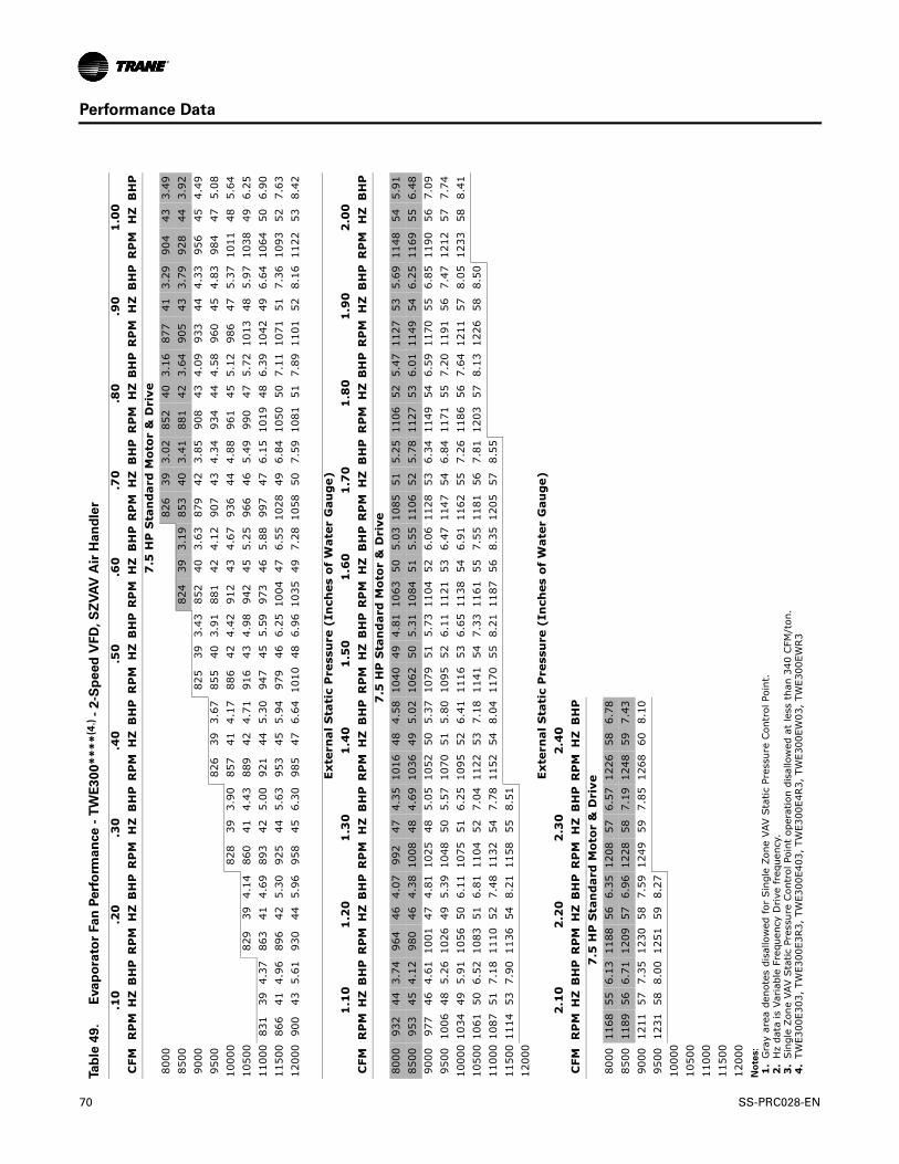
Performance Data
Table 4
9.
E
va
po
rato
r Fan
Perf
orm
an
ce
- T
WE
30
0*
**
*(4
.) -
2-S
pe
ed
VF
D, S
ZV
AV
Air
Ha
nd
ler
CFM
.10
.20
.30
.40
.50
.60
.70
.80
.90
1.0
0R
PM
HZ
BH
PR
PM
HZ
BH
PR
PM
HZ
BH
PR
PM
HZ
BH
PR
PM
HZ
BH
PR
PM
HZ
BH
PR
PM
HZ
BH
PR
PM
HZ
BH
PR
PM
HZ
BH
PR
PM
HZ
BH
P7
.5 H
P S
tan
dar
d M
oto
r &
Dri
ve80
0082
639
3.02
852
403.
1687
741
3.29
904
433.
4985
0082
439
3.19
853
403.
4188
142
3.64
905
433.
7992
844
3.92
9000
825
393.
4385
240
3.63
879
423.
8590
843
4.09
933
444.
3395
645
4.49
9500
826
393.
6785
540
3.91
881
424.
1290
743
4.34
934
444.
5896
045
4.83
984
475.
0810
000
828
393.
9085
741
4.17
886
424.
4291
243
4.67
936
444.
8896
145
5.12
986
475.
3710
1148
5.64
1050
082
939
4.14
860
414.
4388
942
4.71
916
434.
9894
245
5.25
966
465.
4999
047
5.72
1013
485.
9710
3849
6.25
1100
083
139
4.37
863
414.
6989
342
5.00
921
445.
3094
745
5.59
973
465.
8899
747
6.15
1019
486.
3910
4249
6.64
1064
506.
9011
500
866
414.
9689
642
5.30
925
445.
6395
345
5.94
979
466.
2510
0447
6.55
1028
496.
8410
5050
7.11
1071
517.
3610
9352
7.63
1200
090
043
5.61
930
445.
9695
845
6.30
985
476.
6410
1048
6.96
1035
497.
2810
5850
7.59
1081
517.
8911
0152
8.16
1122
538.
42
Ext
ern
al S
tati
c P
ress
ure
(In
ches
of
Wat
er G
aug
e)
CFM
1.1
01
.20
1.3
01
.40
1.5
01
.60
1.7
01
.80
1.9
02
.00
RP
MH
ZB
HP
RP
MH
ZB
HP
RP
MH
ZB
HP
RP
MH
ZB
HP
RP
MH
ZB
HP
RP
MH
ZB
HP
RP
MH
ZB
HP
RP
MH
ZB
HP
RP
MH
ZB
HP
RP
MH
ZB
HP
7.5
HP
Sta
nd
ard
Mo
tor
& D
rive
8000
932
443.
7496
446
4.07
992
474.
3510
1648
4.58
1040
494.
8110
6350
5.03
1085
515.
2511
0652
5.47
1127
535.
6911
4854
5.91
8500
953
454.
1298
046
4.38
1008
484.
6910
3649
5.02
1062
505.
3110
8451
5.55
1106
525.
7811
2753
6.01
1149
546.
2511
6955
6.48
9000
977
464.
6110
0147
4.81
1025
485.
0510
5250
5.37
1079
515.
7311
0452
6.06
1128
536.
3411
4954
6.59
1170
556.
8511
9056
7.09
9500
1006
485.
2610
2649
5.39
1048
505.
5710
7051
5.80
1095
526.
1111
2153
6.47
1147
546.
8411
7155
7.20
1191
567.
4712
1257
7.74
1000
010
3449
5.91
1056
506.
1110
7551
6.25
1095
526.
4111
1653
6.65
1138
546.
9111
6255
7.26
1186
567.
6412
1157
8.05
1233
588.
4110
500
1061
506.
5210
8351
6.81
1104
527.
0411
2253
7.18
1141
547.
3311
6155
7.55
1181
567.
8112
0357
8.13
1226
588.
5011
000
1087
517.
1811
1052
7.48
1132
547.
7811
5254
8.04
1170
558.
2111
8756
8.35
1205
578.
5511
500
1114
537.
9011
3654
8.21
1158
558.
5112
000
Ext
ern
al S
tati
c P
ress
ure
(In
ches
of
Wat
er G
aug
e)
CFM
2.1
02
.20
2.3
02
.40
RP
MH
ZB
HP
RP
MH
ZB
HP
RP
MH
ZB
HP
RP
MH
ZB
HP
7.5
HP
Sta
nd
ard
Mo
tor
& D
rive
8000
1168
556.
1311
8856
6.35
1208
576.
5712
2658
6.78
8500
1189
566.
7112
0957
6.96
1228
587.
1912
4859
7.43
9000
1211
577.
3512
3058
7.59
1249
597.
8512
6860
8.10
9500
1231
588.
0012
5159
8.27
1000
010
500
1100
011
500
1200
0N
ote
s:
1.
Gra
y ar
ea d
enot
es d
isal
low
ed f
or S
ingl
e Zo
ne V
AV S
tatic
Pre
ssur
e Con
trol
Poi
nt.
2.
Hz
data
is V
aria
ble
Freq
uenc
y D
rive
fre
quen
cy.
3.
Sin
gle
Zone
VAV
Sta
tic P
ress
ure
Con
trol
Poi
nt o
pera
tion
disa
llow
ed a
t le
ss t
han
340
CFM
/ton
. 4
.TW
E300
E303
, TW
E300
E3R3,
TW
E300
E403
, TW
E300
E4R3,
TW
E300
EW03
, TW
E300
EWR3
70 SS-PRC028-EN

Performance Data
Table 50. Low Static Fan Motors - Standard Air Handlers
15 Ton — TWE180 — Standard Motor with Field Supplied Sheave & Belt (3 HP)(a)
20 Ton — TWE240Low Static Motor (3 HP)
Motor Sheave Turns Open Nominal RPM Motor Sheave Turns Open Nominal RPM0 649 0 8551 613 1 8122 557 2 7693 500 3 7264 444 4 6835 469 5 640
25 Ton — TWE300 — Standard Motor (7½ HP)(b)
Motor Sheave Turns Open Nominal RPM1 9292 8843 8394 7935 7486 703
(a)TWE180 3HP Standard motor w/ field installed belt and sheavesField Supplied Components Required:Motor Sheave: Variable Pitch (2.4 - 3.4 Inch Pitch Diameter), 0.875 Inch Bore, Single Groove, Browning 1VL40Blower Sheave: Fixed Pitch (9.5 Inch Pitch Diameter), 1.4375 Inch Bore, Single Groove, Browning AX59
(b) TWE300 7½ HP Standard motor w/ field installed belt and sheavesField Supplied Components Required:Motor Sheave: (3.1 - 4.1 Inch Pitch Diameter), 1.125 Inch Bore, Single Groove, Browning 1VL44Blower Sheave: Fixed Pitch (15.4 Inch Pitch Diameter), 1.4375 Inch Bore, Single Groove, Browning BK160Belt: Browning BX70
SS-PRC028-EN 71

Performance Data
Table 51. Standard Fan Motors - Standard Air Handlers
5 Ton — TWE061 — Standard Motor (3/4 HP) 7½ Ton — TWE090 — Standard Motor (1.5 HP)
Motor Sheave Turns Open Nominal RPM Motor Sheave Turns Open Nominal RPM
0 1071 0 847
1 1000 1 791
2 928 2 734
3 857 3 678
4 785 4 621
5 714 5 565
10 Ton — TWE120 — Standard Motor (2 HP) 12½ Ton — TWE150 — Standard Motor (2 HP)
Motor Sheave Turns Open Nominal RPM Motor Sheave Turns Open Nominal RPM
0 818 0 768
1 773 1 725
2 727 2 683
3 682 3 640
4 636 4 598
5 591 5 555
15 Ton — TWE180 — Standard Motor (3 HP) 20 Ton — TWE240 — Standard Motor (5 HP)
Motor Sheave Turns Open Nominal RPM Motor Sheave Turns Open Nominal RPM
0 845 0 966
1 812 1 932
2 728 2 899
3 745 3 865
4 711 4 831
5 678 5 798
6 644 6 764
25 Ton — TWE300 — Standard Motor (7½ HP)
Motor Sheave Turns Open Nominal RPM
1 1068
2 1016
3 964
4 912
5 859
6 807
72 SS-PRC028-EN

Performance Data
Table 52. High Static Fan Motors - Standard Air Handlers
5 Ton — TWE061 — High Static Motor (1½ HP) 7½ Ton — TWE090 — High Static Motor (2 HP)Motor Sheave Turns Open Nominal RPM Motor Sheave Turns Open Nominal RPM
0 1346 0 10941 1279 1 10392 1212 2 9843 1144 3 9304 1077 4 8755 1010 5 820
10 Ton — TWE120High Static Motor (3 HP)
10 Ton — TWE120 — High Static Motor with Field Supplied Sheave & Belt (3 HP)(a)
Motor Sheave Turns Open Nominal RPM Motor Sheave Turns Open Nominal RPM0 972 0 11291 923 1 10732 875 2 10163 826 3 9604 778 4 9035 729 5 847
12½ Ton — TWE150High Static Motor (3 HP)
12½ Ton — TWE150 — High Static Motorwith Field Supplied Sheave & Belt (2 HP)(b)
Motor Sheave Turns Open Nominal RPM Motor Sheave Turns Open Nominal RPM0 913 0 10941 862 1 10392 806 2 9913 749 3 9424 693 4 8935 659 5 820
15 Ton — TWE180High Static Motor (5 HP)
15 Ton — TWE180 — High Static Motorwith Field Supplied Sheave & Belt (5 HP)(c)
Motor Sheave Turns Open Nominal RPM Motor Sheave Turns Open Nominal RPM0 1024 0 12171 989 1 11752 953 2 11183 918 3 10624 882 4 10065 847 5 9646 811 6 964
20 Ton — TWE240 — Standard Motor with Field Supplied Sheave & Belt (5 HP)(d)
25 Ton — TWE300 — Standard Drive with Field Supplied Sheave & Belt (7½ HP)(e)
Motor Sheave Turns Open Nominal RPM Motor Sheave Turns Open Nominal RPM0 1091 0 N/A1 1053 1 13132 1015 2 12493 978 3 11854 940 4 11215 902 5 10576 864 6 993
See next page for notes on required field supplied components
SS-PRC028-EN 73

Performance Data
(a) TWE120 3 HP Hi-Static motor w/ field installed belt and sheavesField Supplied Components Required:Motor Sheave: Variable Pitch (2.8 - 3.8 Inch Pitch Diameter), 0.875 Inch Bore, Single Groove, Browning 1VP44Blower Sheave: Fixed Pitch (6.0 Inch Pitch Diameter), 1.0 Inch Bore, Single Groove, Browning AK64Belt: Browning A50
(b)TWE150 2 HP Hi-Static motor w/ field installed belt and sheavesField Supplied Components Required:Motor Sheave: Variable Pitch (2.4 - 3.4 Inch Pitch Diameter), 0.875 Inch Bore, Single Groove, Browning 1VL40Blower Sheave: Fixed Pitch (6.7 Inch Pitch Diameter), 1.4375 Inch Bore, Single Groove, Browning AK71Belt: Browning A55
(c)TWE180 5 HP Hi-Static motor w/ field installed belt and sheavesField Supplied Components Required:Motor Sheave: Variable Pitch (3.4 - 4.4 Inch Pitch Diameter), 1.125 Inch Bore, Single Groove, Browning 1VP50Blower Sheave: Fixed Pitch (6.6 Inch Pitch Diameter), 1.4375 Inch Bore, Single Groove, Browning BK72Belt: Browning BX58
(d) TWE240 5 HP Standard motor w/ field installed belt and sheavesField Supplied Components Required:Motor Sheave: Variable Pitch (3.4 - 4.4 Inch Pitch Diameter), 1.125 Inch Bore, Single Groove, Browning 1VP50Blower Sheave: Fixed Pitch (7.4 Inch Pitch Diameter), 1.4375 Inch Bore, Single Groove, Browning BK115Belt: Browning BX57
(e) TWE300 7½ HP Standard motor w/ field installed belt and sheavesField Supplied Components Required:Motor Sheave: Variable Pitch (3.1 - 4.1 Inch Pitch Diameter), 1.125 Inch Bore, Single Groove, Browning 1VP50Blower Sheave: Fixed Pitch (10.9 Inch Pitch Diameter), 1.4375 Inch Bore, Single Groove, Browning BK115Belt: Browning BX63
Table 53. Ultra High Static Fan Motors - Standard Air Handlers
7½ Ton — TWE090Ultra High Static Motor (3 HP)
12½ Ton — TWE150 Ultra High Static Motor (5 HP)
Motor Sheave Turns Open Nominal RPM Motor Sheave Turns Open Nominal RPM0 1346 0 12171 1241 1 11752 1136 2 11333 1030 3 10914 925 4 10485 820 5 1006— — 6 964
20 Ton — TWE240 — Ultra High Static Motor (7.5 HP)
20 Ton — TWE240 — Ultra High Static Motor with Field Supplied Sheave & Belt (7.5 HP)(a)
Motor Sheave Turns Open Nominal RPM Motor Sheave Turns Open Nominal RPM0 1294 0 13151 1243 1 12812 1191 2 12433 1140 3 12054 1089 4 11685 1037 5 11006 986 6 1111
(a)TWE240 7½ HP Ultra Hi-Static motor w/ field installed belt and sheavesField Supplied Components Required:Motor Sheave: Variable Pitch (2.8 - 3.8 Inch Pitch Diameter), 1.125 Inch Bore, Single Groove, Browning 1VP44Blower Sheave: Fixed Pitch (10.4 Inch Pitch Diameter), 1.4375 Inch Bore, Single Groove, Browning BK110Belt: Browning BX62
74 SS-PRC028-EN
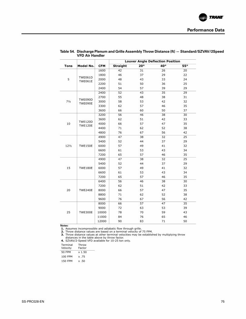
Performance Data
Table 54. Discharge Plenum and Grille Assembly Throw Distance (ft) — Standard/SZVAV/2Speed VFD Air Handler
Tons Model No.Louver Angle Deflection Position
CFM Straight 20° 40° 55°
5TWE061DTWE061E
1600 42 31 26 201800 46 37 29 222000 48 43 33 242200 51 50 36 252400 54 57 39 29
7½ TWE090DTWE090E
2400 52 43 35 292700 55 48 38 313000 58 53 42 323300 62 57 46 353600 66 60 50 37
10TWE120DTWE120E
3200 56 46 38 303600 62 51 42 334000 66 57 47 354400 71 62 52 384800 76 67 56 42
12½ TWE150E
4900 47 38 32 255400 52 44 37 296000 57 49 41 326600 61 53 43 347200 65 57 46 35
15 TWE180E
4900 47 38 32 255400 52 44 37 296000 57 49 41 326600 61 53 43 347200 65 57 46 35
20 TWE240E
6400 56 46 38 307200 62 51 42 338000 66 57 47 358800 71 62 52 389600 76 67 56 42
25 TWE300E
8000 66 57 47 359000 72 63 53 3910000 78 70 59 4311000 84 76 65 4612000 90 83 71 50
Notes:
1. Assumes incompressible and adiabatic flow through grille. 2. Throw distance values are based on a terminal velocity of 75 FPM. 3. Throw distance values at other terminal velocities may be established by multiplying throw
distances in the table above by throw factor. 4. SZVAV/2-Speed VFD available for 10-25 ton only.Terminal Velocity
Throw Factor
50 FPM x 1.50
100 FPM x .75
150 FPM x .50
SS-PRC028-EN 75

Performance Data
Table 55. Electric Heat Discharge Plenum and Grille Airflow (CFM) - Standard/SZVAV/2-Speed VFD(a) Air Handler
(a) SZVAV/2-Speed VFD available for 10-25 ton only.
Tons Unit Model No.Electric Heater
Model No.Airflow (CFM)
Minimum Maximum
5TWE061D1, E1TWE061D3, E3TWE061D4, E4
BAYHTRL117A 2000 2400BAYHTRL315A 2000 2400BAYHTRL415A 2000 2400
7½TWE090D1, E1TWE090D3, E3
TWE090D3, E3(b)
BAYHTRL117A 3000 3600BAYHTRL123A 3375 3600BAYHTRL315A 2625 3600BAYHTRL325A 3000 3600BAYHTRL415A 2625 3600BAYHTRL425A 2625 3600
10
TWE120D1, E1TWE120D3, E3
TWE120D3, E3(b)
TWE120D4, E4
(b)Standard Air Handler wired for 460 volt, use with BAYHTR*4** only. See “Electric Heaters,” p. 16.
BAYHTRL117A 3500 4800BAYHTRL123A 4000 4800BAYHTRL315A 4000 4800BAYHTRL325A 3500 4800BAYHTRL415A 3500 4800BAYHTRL425A 3500 4800
12½ TWE150E3TWE150E3(b), TWE150E4
BAYHTRM330A 5250 6000BAYHTRM430A 5250 6000
15TWE180E3
TWE180E3(b), TWE180E4BAYHTRM330A 5250 7200BAYHTRM430A 5250 7200
20TWE240E3TWE240E4
BAYHTRM330A 7000 9600BAYHTRM430A 7000 9600
25 TWE300E3TWE300E4
BAYHTRM330A 8750 12000BAYHTRM430A 8750 12000
Table 56. Static Pressure Drop Through Accessories (inches of water column)(a) — Standard/SZVAV/2-Speed VFD(b) Air Handler
Tons Unit Model No. CFMReturn Grille
Discharge Plenum and
Grille(c)
Electric Heaters (kW) Hydronic Coils
5-10 15-20 25-30 35-50 Steam Hot Water
TWE061DTWE061E
1600 0.12 0.21 0.08 0.08 0.14 — 0.44 0.315 2000 0.18 0.33 0.13 0.13 0.19 — 0.62 0.44
2400 0.28 0.47 0.19 0.19 0.37 — 0.80 0.59
TWE090DTWE090E
2400 0.08 0.27 0.03 0.06 0.08 0.12 0.38 0.237½ 3000 0.13 0.4 0.06 0.12 0.17 0.23 0.50 0.33
3600 0.18 0.58 0.08 0.16 0.24 0.32 0.66 0.44
TWE120DTWE120E
3200 0.07 0.43 0.06 0.13 0.19 0.26 0.42 0.4010 4000 0.11 0.66 0.10 0.20 0.30 0.40 0.59 0.56
4800 0.15 0.95 0.14 0.28 0.42 0.57 0.76 0.75
12½ TWE150E4000 0.06 0.16 0.02 0.02 0.04 0.08 0.28 0.245000 0.10 0.25 0.03 0.03 0.08 0.12 0.44 0.386000 0.14 0.36 0.04 0.05 0.12 0.17 0.64 0.544800 0.09 0.23 0.03 0.03 0.06 0.08 0.46 0.38
15 TWE180E 6000 0.15 0.34 0.06 0.06 0.12 0.17 0.64 0.547200 0.2 0.49 0.08 0.08 0.16 0.24 0.82 0.72
76 SS-PRC028-EN

Performance Data
6400 0.11 0.43 0.06 0.06 0.13 0.19 0.50 0.4120 TWE240E 8000 0.17 0.66 0.10 0.10 0.20 0.30 0.70 0.58
9600 0.23 0.95 0.14 0.14 0.28 0.42 0.89 0.78
25 TWE300E8000 0.17 0.66 0.10 0.10 0.20 0.30 0.70 0.5810000 0.25 1.03 0.15 0.15 0.30 0.45 0.94 0.8312000 0.32 1.49 0.20 0.20 0.42 0.62 1.16 1.14
(a) Return air filter ESP included in Fan Performance Table data.(b) SZVAV/2-Speed VFD available for 10-25 ton only.(c) At louver opening angle of 42 degrees. For ESP at other angle openings, see accessory installation instructions.
Table 56. Static Pressure Drop Through Accessories (inches of water column)(a) — Standard/SZVAV/2-Speed VFD(b) Air Handler
Tons Unit Model No. CFMReturn Grille
Discharge Plenum and
Grille(c)
Electric Heaters (kW) Hydronic Coils
5-10 15-20 25-30 35-50 Steam Hot Water
Table 57. Auxiliary Electric Heat Capacity - Standard/SZVAV/2-Speed(a) Air Handler
Unit Model No.Total kW
No. of Stages
Stage 1 Stage 2 Total
kW InputBTUH
Output kW InputBTUH
Output kW InputBTUH
Output
TWE061D3, TWE061D4, TWE061DW, TWE061E3,
TWE061E4
5.00 1 5.00 17,065 - - 5.00 17,0659.96 1 9.96 33,993 - - 9.96 33,99314.96 1 14.96 51,058 - - 14.96 51,05824.92 2 14.96 51,058 9.96 33,993 24.92 85,051
TWE090D3(b),TWE120D3(b),TWE120DW, TWE090E3(b),
TWE120D4, TWE120E4,TWE120E3(b), TWE120EW
5.00 1 5.00 17,065 - - 5.00 17,0659.96 1 9.96 33,993 - - 9.96 33,99314.96 1 14.96 51,058 - - 14.96 51,05824.92 2 14.96 51,058 9.96 33,993 24.92 85,051
TWE061D1,TWE090D1,TWE120D1, TWE061E1,TWE090E1, TWE120E1
5.76 1 5.76 19,659 - - 5.76 19,65911.52 1 11.52 39,318 - - 11.52 39,31817.28 1 17.28 58,977 - - 17.28 58,97723.04 2 11.52 39,318 11.52 39,318 23.04 78,636
TWE090D1,TWE120D1, TWE090D3(b), TWE120E1, TWE120D3(b), TWE120D4, TWE120DW, TWE120E3(b),
TWE120E4, TWE120EW
28.8 2 17.28 58,977 11.52 39,318 28.8 98,29534.88 2 19.92 67,987 14.96 51,058 34.88 119,045
10.00 1 10.00 34,130 - - 10.00 34,130
TWE150E, TWE180E, TWE240E, TWE300E
10.00 1 10.00 34,130 - - 10.00 34,13019.92 1 19.92 67,987 - - 19.92 67,98729.92 2 19.92 67,987 10.00 34,130 29.92 102,11749.84 2 29.92 102,117 19.92 67,987 49.84 170,104
Note: Heaters are rated at 240V, 480V and 600V. For other than rated voltage capacity = (Voltage/Related Voltage)2 x Rated Capacity.
(a) SZVAV/2-Speed VFD available for 10-25 ton only.(b) Standard Air Handler field converted to 460V.
SS-PRC028-EN 77

Performance Data
Table 58. Steam Heating Coil Capacity - Standard/SZVAV/2-Speed VFD(a) Air Handlers Steam Pressure (PSIG)
Unit Model No.
Airflow(CFM)
EAT(°F)
Steam Pressure (PSIG)
2 PSI 5 PSI 10 PSI 15 PSI 25 PSI
LAT(b)
MBh(c)
Cond.lb/
hr(d)LAT(b)
MBh(c)
Cond.lb/
hr(d)LAT(b)
MBh(c)
Cond.lb/
hr(d)LAT(b)
MBh(c)
Cond.lb/
hr(d)LAT(b)
MBh(c)
Cond.lb/
hr(d)
TWE061DTWE061E
1600
40 97 99 103 100 104 108 104 111 117 108 117 124 113 127 136
60 111 88 91 114 93 97 118 100 105 121 106 112 127 116 124
80 125 77 80 127 82 85 131 89 94 135 95 101 140 105 112
2000
40 90 108 112 93 114 118 96 122 128 99 129 136 104 139 149
60 104 96 100 107 102 106 111 110 115 114 116 123 119 127 136
80 119 84 87 121 90 93 125 98 102 128 104 110 133 115 123
2400
40 85 116 120 87 123 127 90 131 137 93 138 146 98 150 160
60 100 104 107 102 110 114 105 118 124 108 125 132 113 137 146
80 115 91 94 117 97 100 120 105 110 123 112 118 127 123 132
TWE090DTWE090E
2400
40 102 162 168 106 171 177 110 182 191 114 192 203 120 208 222
60 115 144 149 119 152 158 123 164 172 127 174 184 133 190 203
80 129 126 130 132 134 140 136 146 153 140 155 164 146 171 183
3000
40 95 178 183 97 187 194 101 200 209 105 210 222 110 228 244
60 109 158 163 111 167 174 115 180 188 119 190 201 124 208 222
80 122 138 143 125 147 153 129 160 168 132 170 180 138 188 201
3600
40 89 191 197 91 201 208 95 215 225 97 226 239 103 245 262
60 103 170 175 106 180 187 110 193 203 112 205 216 117 224 239
80 118 149 154 121 158 164 124 172 180 127 183 194 132 202 216
TWE120DTWE120E
3200
40 99 203 210 102 214 222 106 229 240 109 241 254 115 261 279
60 112 181 187 115 191 199 119 206 216 123 218 230 129 238 255
80 126 158 164 129 169 175 133 183 192 136 195 206 142 215 230
4000
40 91 222 229 94 234 243 98 250 262 101 264 278 106 286 306
60 106 198 204 108 209 217 112 225 236 115 239 252 120 261 279
80 120 173 179 123 184 192 126 200 210 129 214 226 134 236 252
4800
40 86 239 246 88 251 261 92 269 282 94 284 299 99 307 329
60 101 212 219 103 225 233 107 242 254 109 257 271 114 280 300
80 116 186 192 118 198 206 121 215 226 124 230 243 129 253 271
TWE150E
4000
40 103 274 283 106 288 299 111 308 323 115 325 343 121 352 376
60 116 244 252 119 258 268 124 277 291 128 294 310 134 321 343
80 129 213 220 132 227 236 137 247 259 141 263 278 147 290 310
5000
40 95 300 309 98 316 328 102 337 354 106 356 346 111 286 412
60 109 267 275 112 282 293 116 304 318 119 322 340 125 352 376
80 123 234 241 126 249 259 130 270 283 133 288 305 139 318 340
6000
40 90 322 332 92 339 352 96 363 380 99 383 404 104 415 444
60 104 287 296 107 303 315 110 327 342 113 347 366 118 379 405
80 119 251 259 121 268 278 125 291 305 128 310 328 133 342 366
Continued on next page
78 SS-PRC028-EN

Performance Data
TWE180E
4800
40 97 295 304 100 310 322 104 332 348 107 350 369 113 379 406
60 110 262 271 113 278 288 117 299 313 121 317 334 126 346 370
80 124 230 237 127 245 254 131 266 279 134 284 299 140 313 334
6000
40 90 322 332 92 339 352 96 363 380 99 383 404 104 415 444
60 104 287 296 107 303 315 110 327 343 113 347 366 118 379 405
80 119 251 259 121 268 278 125 291 305 128 310 328 133 342 366
7200
40 84 346 356 87 364 378 90 390 408 93 411 434 97 446 477
60 99 308 318 102 326 338 105 351 368 108 373 393 112 407 435
80 115 270 278 117 287 299 120 313 327 123 334 352 127 368 394
TWE240E
6400
40 95 379 391 97 399 414 102 427 447 105 450 475 110 488 522
60 109 337 348 111 357 371 115 384 403 119 408 430 124 445 476
80 123 295 305 125 315 327 129 342 358 133 365 385 138 402 430
8000
40 88 414 426 90 436 452 94 467 488 97 492 519 102 534 571
60 102 368 380 105 390 405 108 420 440 111 446 470 116 487 521
80 117 322 333 120 344 357 123 374 392 126 399 421 131 440 471
9600
40 83 443 457 85 468 485 88 501 524 91 529 558 95 574 613
60 98 395 407 100 418 434 103 451 473 106 479 505 110 524 560
80 113 346 357 115 369 383 119 402 421 121 429 453 125 473 506
TWE300E
8000
40 88 414 426 90 436 452 94 467 488 97 492 519 102 534 571
60 102 368 380 105 390 405 108 420 440 111 446 470 116 487 521
80 117 322 333 120 344 357 123 374 392 126 399 421 131 440 471
10000
40 82 450 464 84 475 492 87 509 533 90 537 567 94 583 623
60 97 401 413 99 425 441 102 459 480 105 487 513 109 532 569
80 112 352 363 115 375 389 118 408 427 120 436 460 124 481 514
12000
40 77 479 493 79 509 527 82 546 571 84 577 608 88 627 669
60 93 430 443 95 456 473 98 492 515 100 523 551 104 572 611
80 109 377 389 111 402 418 114 438 459 116 468 494 120 517 553
Notes: Type NS Coil, 1 Row, 1" OD, SF Fins, 132 Fins per Foot.
(a)SZVAV/2-Speed VFD available for 10-25 ton only.(b)LAT - Leaving Air Temperature (°F)(c)MBh Capacity: BTU/HR/1000(d)Cond. Lb/Hr - Condensate pound per hour
Table 58. (continued) Steam Heating Coil Capacity - Standard/SZVAV/2-Speed VFD(a) Air Handlers Steam Pressure
Unit Model No.
Airflow(CFM)
EAT(°F)
Steam Pressure (PSIG)
2 PSI 5 PSI 10 PSI 15 PSI 25 PSI
LAT(b)
MBh(c)
Cond.lb/
hr(d)LAT(b)
MBh(c)
Cond.lb/
hr(d)LAT(b)
MBh(c)
Cond.lb/
hr(d)LAT(b)
MBh(c)
Cond.lb/
hr(d)LAT(b)
MBh(c)
Cond.lb/
hr(d)
SS-PRC028-EN 79

Performance Data
Table 5
9.
Ho
t W
ate
r H
ea
tin
g C
oil
Ca
pacit
y -
Sta
nd
ard
/SZ
VA
V/2
-Sp
eed
VF
D(a
) A
ir H
an
dle
r
Ton
sU
nit
Mo
del
N
o.A
irfl
ow
(C
FM)
Ente
rin
g A
ir
Tem
p.
(°F)
En
teri
ng
Wat
er T
emp
erat
ure
(°F
)1
80
Wat
er T
emp
erat
ure
Dro
p (
°F)
20
.03
0.0
40
.0G
PM
(b)
MB
h(c
)LA
T(d
)G
PM
(b)
MB
h(c
)LA
T(d
)G
PM
(b)
MB
h(c
)LA
T(d
)
5
4010
.910
6.1
101.
06.
696
.596
.04.
587
.490
.016
0060
9.0
88.3
111.
05.
479
.110
6.0
3.6
70.3
100.
080
7.2
70.6
121.
04.
261
.811
6.0
2.7
53.4
111.
0TW
E061
D,
4012
.311
9.8
95.0
7.4
108.
690
.05.
097
.985
1.0
TWE0
61E
2000
6010
.299
.610
6.0
6.1
88.8
101.
04.
078
.696
.080
8.1
79.5
117.
04.
769
.211
2.0
3.0
59.6
107.
040
13.5
132.
091
.08.
111
9.2
86.0
5.5
107.
181
1.0
2400
6011
.210
9.6
102.
06.
697
.497
.04.
485
.993
1.0
809.
087
.411
4.0
5.2
75.7
109.
03.
364
.910
5.0
7½
4017
.016
5.9
104.
010
.415
2.3
98.0
7.1
139.
293
.024
0060
14.2
138.
411
3.0
8.5
125.
210
8.0
5.7
112.
510
3.0
8011
.411
1.1
123.
06.
798
.311
8.0
4.4
86.1
113.
0TW
E090
D,
4019
.318
7.9
9811
.717
1.9
938.
015
6.5
88TW
E090
E30
0060
16.1
156.
710
8.0
9.6
141.
110
3.0
6.4
126.
399
1.0
8012
.912
5.5
119.
07.
511
0.6
114.
04.
996
.511
0.0
4021
.220
7.3
93.0
12.9
189.
188
.08.
817
1.6
84.0
3600
6017
.717
2.7
104.
010
.615
5.0
100.
07.
113
8.3
95.0
8014
.213
8.2
115.
08.
312
1.2
111.
05.
410
5.4
107.
0
10
4024
.523
9.1
109.
014
.321
0.0
100.
09.
117
8.7
91.0
3200
6020
.219
7.3
117.
011
.516
8.4
108.
06.
913
4.8
99.0
8015
.915
5.6
125.
08.
612
6.1
116.
04.
078
.710
3.0
TWE1
20D
,40
27.8
271.
710
3.0
16.2
237.
595
.010
.320
1.9
86.0
TWE1
20E
4000
6022
.922
3.8
112.
013
.019
0.3
104.
07.
815
3.3
95.0
8018
.117
6.2
121.
09.
714
2.6
113.
05.
097
.310
2.0
4030
.730
0.0
98.0
17.8
261.
390
.011
.322
1.7
82.0
4800
6025
.324
6.9
107.
014
.320
9.1
100.
08.
616
8.9
92.0
8019
.919
4.0
117.
010
.715
6.7
110.
05.
611
0.2
101.
0
12½
TWE1
50E
4031
.731
8.0
113.
319
.228
7.7
106.
312
.825
6.5
99.1
4000
6026
.426
4.4
120.
915
.623
4.4
114.
010
.220
3.2
106.
980
21.1
210.
912
8.6
12.1
181.
112
1.7
7.4
148.
911
4.3
4036
.036
0.6
106.
521
.732
5.2
100.
014
.428
8.8
93.3
5000
6029
.929
9.6
115.
317
.626
4.5
108.
811
.422
8.3
102.
180
23.8
238.
712
4.0
13.6
203.
811
7.6
8.4
167.
511
0.9
4039
.739
7.0
101.
023
.835
7.0
94.9
15.8
316.
188
.660
0060
32.9
329.
611
0.7
19.3
290.
010
4.6
12.5
249.
598
.380
26.2
262.
312
0.3
14.9
223.
111
4.3
9.1
182.
810
8.1
con
tin
ued
on
nex
t p
age
80 SS-PRC028-EN

Performance Data
Ton
sU
nit
Mo
del
N
o.A
irfl
ow
(C
FM)
Ente
rin
g A
ir
Tem
p.
(°F)
En
teri
ng
Wat
er T
emp
erat
ure
(°F
)1
80
Wat
er T
emp
erat
ure
Dro
p (
°F)
20
.03
0.0
40
.0G
PM
(b)
MB
h(c
)LA
T(d
)G
PM
(b)
MB
h(c
)LA
T(d
)G
PM
(b)
MB
h(c
)LA
T(d
)
15
4035
.234
3.9
106.
021
.231
0.3
100.
014
.127
6.3
93.0
4800
6029
.328
5.7
115
17.2
252.
710
8.0
11.2
218.
510
2.0
8023
.322
7.7
124.
013
.319
5.0
117.
08.
215
9.9
111.
040
40.0
390.
310
0.0
23.9
350.
894
.015
.931
1.4
884.
0TW
E180
E60
0060
33.3
323.
911
0.0
19.5
285.
310
4.0
12.6
246.
298
.080
26.4
257.
712
0.0
15.0
219.
911
4.0
9.2
180.
510
8.0
4044
.243
1.3
95.0
26.4
386.
589
.017
.534
2.1
84.0
7200
6036
.635
7.6
106.
021
.431
3.9
100.
013
.827
0.6
95.0
8029
.128
4.2
116.
016
.524
1.6
111.
010
.119
8.3
105.
0
20
4046
.845
6.2
106.
028
.441
6.5
100.
019
.337
6.7
94.0
6400
6039
.038
0.2
115.
023
.334
1.2
109.
015
.430
1.7
103.
080
31.2
304.
512
4.0
18.2
266.
011
8.0
11.6
227.
011
3.0
4053
.051
7.5
100.
032
.147
0.9
94.0
21.7
424.
589
.0TW
E240
E80
0060
44.2
430.
911
0.0
26.3
385.
210
4.0
17.4
339.
699
.080
35.3
344.
612
0.0
20.5
299.
811
5.0
13.0
255.
210
9.0
4058
.657
2.0
94.0
35.4
519.
190
.023
.946
6.8
85.0
9600
6048
.847
5.9
106.
028
.942
4.2
101.
019
.137
3.3
96.0
8039
.038
0.2
116.
022
.532
9.6
112.
014
.328
0.0
107.
0
25
4052
.052
0.2
100.
031
.647
4.4
94.7
21.4
427.
689
.380
0060
43.3
433.
611
0.0
25.9
388.
210
4.7
17.1
341.
699
.480
34.7
347.
012
0.0
20.1
301.
911
4.8
12.8
255.
310
9.4
4057
.957
9.4
93.4
35.1
526.
988
.623
.747
3.6
83.7
TWE3
00E
1000
060
48.2
482.
510
4.5
28.7
430.
699
.718
.937
7.7
94.8
8038
.538
5.7
115.
622
.333
4.3
110.
814
.128
1.6
106.
040
62.8
628.
688
.338
.057
0.5
83.8
25.6
511.
779
.312
000
6052
.352
3.2
100.
231
.046
5.8
95.8
20.4
407.
591
.380
41.7
417.
911
2.2
24.1
361.
210
7.8
15.2
303.
310
3.3
con
tin
ued
on
nex
t p
age
Tab
le 5
9.
Ho
t W
ate
r H
ea
tin
g C
oil
Ca
pacit
y -
Sta
nd
ard
/SZ
VA
V/2
-Sp
eed
VF
D(a
) A
ir H
an
dle
r (c
on
tin
ued
)
SS-PRC028-EN 81

Performance Data
Ton
sU
nit
Mo
del
N
o.A
irfl
ow
(C
FM)
Ente
rin
g A
ir
Tem
p.
(°F)
En
teri
ng
Wat
er T
emp
erat
ure
(°F
)2
00
.0W
ater
Tem
per
atu
re D
rop
(°F
)2
0.0
30
.04
0.0
GP
M(b
)M
Bh
(c)
LAT
(d)
GP
M(b
)M
Bh
(c)
LAT
(d)
GP
M(b
)M
Bh
(c)
LAT
(d)
5TW
E061
D,
TWE0
61E
1600
4012
.912
4.9
112.
07.
911
5.4
106.
05.
510
6.3
101.
060
11.0
107.
012
2.0
6.7
97.8
116.
04.
688
.911
1.0
809.
289
.113
1.0
5.5
80.2
126.
03.
771
.712
1.0
2000
404.
514
1.3
105.
08.
913
0.1
100.
06.
111
9.4
95.0
6012
.412
0.9
116.
07.
511
0.1
111.
05.
199
.710
6.0
8010
.410
0.6
126.
06.
290
.212
2.0
4.1
80.3
117.
0
2400
406.
015
5.8
100.
09.
814
3.1
95.0
6.7
131.
090
.060
3.7
133.
311
1.0
8.3
120.
910
6.0
5.6
109.
210
2.0
8011
.411
0.8
123.
06.
898
.911
8.0
4.5
87.8
114.
0
7½TW
E090
D,
TWE0
90E
2400
4020
.019
4.8
115.
012
.418
1.2
110.
08.
616
8.2
105.
060
17.2
167.
112
4.0
10.6
153.
911
9.0
7.2
141.
211
4.0
8014
.413
9.6
134.
08.
712
6.8
129.
05.
911
4.3
124.
0
3000
4022
.722
0.9
108
14.0
204.
910
3.0
9.7
189.
698
.060
9.5
189.
411
8.0
11.9
173.
911
3.0
8.2
159.
010
9.0
8016
.315
8.1
129.
09.
814
3.0
124.
06.
612
8.5
119.
0
3600
4025
.124
4.0
102.
015
.522
5.7
981.
00.
720
8.4
93.0
6021
.520
9.1
113.
013
.119
1.4
109.
09.
017
4.4
105.
080
17.9
174.
312
5.0
10.8
157.
112
0.0
7.2
140.
911
6.0
10TW
E120
D,
TWE1
20E
3200
4029
.328
4.7
122.
017
.625
6.8
114.
011
.722
8.6
106.
060
25.0
242.
613
0.0
14.7
215.
212
2.0
9.6
186.
911
4.0
8020
.620
0.6
138.
011
.917
3.6
130.
07.
414
4.3
122.
0
4000
4033
.432
4.1
115.
019
.929
1.0
107.
013
.325
8.2
99.0
6028
.427
5.8
124.
016
.724
3.6
116.
010
.821
1.0
109.
080
23.4
227.
713
2.0
13.4
196.
212
5.0
8.4
163.
211
8.0
4800
4036
.935
8.3
109.
022
.032
0.7
102.
014
.628
3.7
94.0
6031
.430
4.7
118.
018
.426
8.1
111.
011
.923
1.6
104.
080
25.9
251.
312
8.0
14.8
215.
612
1.0
9.2
179.
411
4.0
12½
TWE1
50E
4037
.337
4.5
126.
323
.034
5.9
119.
715
.831
6.5
113.
040
0060
32.0
320.
913
4.0
19.4
292.
512
7.4
13.1
263.
112
0.7
8026
.626
7.4
141.
615
.929
3.1
135.
110
.520
9.7
128.
340
42.4
425.
411
8.5
26.0
391.
711
2.2
17.8
357.
210
5.9
5000
6036
.336
4.3
127.
222
.033
0.8
121.
014
.829
6.5
114.
780
30.2
303.
213
5.9
17.9
269.
912
9.8
11.8
235.
812
3.5
4046
.746
8.8
112.
028
.643
0.6
106.
219
.539
1.7
100.
260
0060
40.0
401.
212
1.7
24.2
363.
311
5.8
16.2
324.
810
9.9
8033
.233
3.6
131.
319
.729
6.1
125.
512
.925
7.8
119.
6co
nti
nu
ed o
n n
ext
pag
e
Tab
le 5
9.
Ho
t W
ate
r H
ea
tin
g C
oil
Ca
pacit
y -
Sta
nd
ard
/SZ
VA
V/2
-Sp
eed
VF
D(a
) A
ir H
an
dle
r (c
on
tin
ued
)
82 SS-PRC028-EN

Performance Data
15TW
E180
E
4800
4041
.840
6.0
118.
025
.637
3.4
112.
017
.534
1.0
105.
060
35.8
347.
512
7.0
21.6
315.
412
1.0
14.6
283.
411
4.0
8029
.828
9.1
135.
017
.725
7.6
129.
011
.622
5.7
123.
0
6000
407.
546
1.4
111.
029
.042
3.0
105.
019
.838
5.0
99.0
6040
.639
4.6
121.
024
.535
6.9
115.
016
.431
9.6
109.
080
33.8
327.
913
0.0
19.9
291.
012
5.0
13.1
254.
311
9.0
7200
4052
.551
0.4
105.
032
.046
6.7
100.
021
.842
3.8
94.0
6044
.943
6.3
116.
027
.039
3.5
110.
018
.035
1.4
105.
080
37.3
362.
212
6.0
22.0
320.
512
1.0
14.3
279.
511
6.0
20
6400
4055
.253
6.5
117.
034
.149
7.8
112.
023
.645
9.4
106.
060
47.4
460.
212
6.0
28.9
422.
112
1.0
19.7
384.
211
5.0
8039
.538
4.0
135.
023
.834
6.5
130.
015
.930
8.9
124.
0
8000
4062
.760
9.2
110.
038
.656
3.8
105.
026
.651
8.8
100.
0TW
E240
E60
53.8
522.
212
0.0
32.7
477.
611
5.0
22.2
433.
311
0.0
8044
.843
5.4
130.
026
.839
1.5
125.
017
.934
7.9
120.
0
9600
4069
.467
3.9
105.
042
.762
2.3
100.
029
.357
1.5
95.0
6059
.457
7.4
115.
036
.152
6.8
111.
024
.547
6.7
106.
080
49.5
481.
012
6.0
29.6
431.
412
1.0
19.6
382.
611
7.0
25
4060
.961
1.5
110.
537
.756
7.6
105.
426
.152
3.0
100.
380
0060
52.3
524.
612
0.5
32.0
481.
111
5.5
21.8
436.
711
0.3
8043
.643
7.8
130.
526
.239
4.6
125.
517
.535
0.3
120.
440
67.9
681.
610
2.9
42.0
631.
298
.228
.958
0.2
93.5
TWE3
00E
1000
060
58.2
584.
411
3.9
35.5
534.
510
9.3
24.1
483.
910
4.6
8048
.648
7.4
124.
929
.143
7.9
120.
419
.338
7.5
115.
740
73.7
740.
096
.945
.568
4.0
92.6
31.3
627.
788
.212
000
6063
.263
4.2
108.
738
.557
8.9
104.
526
.152
3.0
100.
280
52.7
528.
612
0.6
31.5
473.
811
6.4
20.9
418.
311
2.1
con
tin
ued
on
nex
t p
age
Tab
le 5
9.
Ho
t W
ate
r H
ea
tin
g C
oil
Ca
pacit
y -
Sta
nd
ard
/SZ
VA
V/2
-Sp
eed
VF
D(a
) A
ir H
an
dle
r (c
on
tin
ued
)
SS-PRC028-EN 83

Performance Data
Ton
sU
nit
Mo
del
N
o.A
irfl
ow
(C
FM)
Ente
rin
g A
ir
Tem
p.
(°F)
En
teri
ng
Wat
er T
emp
erat
ure
(°F
)2
10
.0W
ater
Tem
per
atu
re D
rop
(°F
)2
0.0
30
.04
0.0
GP
M(b
)M
Bh
(c)
LAT
(d)
GP
M(b
)M
Bh
(c)
LAT
(d)
GP
M(b
)M
Bh
(c)
LAT
(d)
5
1600
4013
.913
4.3
117.
08.
612
4.8
112.
06.
011
5.8
107.
060
12.0
116.
312
7.0
7.4
107.
112
2.0
5.1
98.3
117.
080
10.2
98.4
137.
06.
189
.513
2.0
4.2
80.9
127.
0TW
E061
D,
2000
4015
.715
2.0
110.
09.
714
0.9
105.
06.
713
0.2
100.
0TW
E061
E60
13.6
131.
612
1.0
8.3
120.
711
6.0
5.7
110.
511
1.0
8011
.511
1.2
131.
06.
910
0.7
126.
04.
790
.712
2.0
2400
4017
.316
7.7
104.
010
.615
5.0
99.0
7.4
142.
995
.060
15.0
145.
111
6.0
9.1
132.
811
1.0
6.2
121.
010
6.0
8012
.612
2.6
127.
07.
611
0.6
122.
05.
199
.311
8.0
7½
2400
4021
.620
9.2
120.
013
.419
5.7
115.
09.
418
2.7
110.
060
18.7
181.
513
0.0
11.6
168.
312
5.0
8.0
155.
612
0.0
8015
.915
3.9
139.
09.
714
1.0
134.
06.
628
.612
9.0
TWE0
90D
,30
0040
24.5
237.
411
3.0
15.2
221.
510
8.0
10.6
206.
210
3.0
TWE0
90E
6021
.220
5.8
123.
013
.119
0.3
118.
09.
017
5.4
114.
080
18.0
174.
413
4.0
10.9
159.
212
9.0
7.4
144.
712
4.0
3600
4027
.126
2.3
107.
016
.824
4.1
102.
011
.722
6.8
98.0
6023
.422
7.3
118.
014
.420
9.6
114.
09.
919
2.6
109.
080
19.8
192.
412
9.0
12.0
175.
212
5.0
8.2
158.
712
1.0
10
3200
4031
.730
7.4
129.
019
.227
9.9
121.
013
.025
2.6
113.
060
27.4
265.
113
6.0
16.4
238.
212
9.0
10.9
211.
012
1.0
8023
.022
3.0
144.
013
.519
6.5
137.
08.
716
9.1
129.
0TW
E120
D,
4000
4036
.135
0.2
121.
021
.831
7.6
113.
014
.728
5.5
106.
0TW
E120
E60
31.1
301.
713
0.0
18.5
269.
912
2.0
12.3
238.
211
5.0
8026
.125
3.4
138.
015
.322
2.3
131.
09.
819
0.8
124.
0
4800
4040
.038
7.4
114.
024
.135
0.3
107.
016
.231
3.9
100.
060
34.4
333.
612
4.0
20.4
297.
311
7.0
13.5
261.
711
0.0
8028
.927
9.9
134.
016
.824
4.6
127.
010
.820
9.5
120.
0
12½
TWE1
50E
4040
.140
2.7
132.
824
.937
4.7
126.
417
.234
6.1
119.
840
0060
34.7
349.
114
0.5
21.3
321.
313
4.1
14.6
292.
712
7.5
8029
.429
5.5
148.
117
.826
7.8
141.
711
.923
9.2
135.
140
45.5
457.
612
4.4
28.2
424.
611
8.3
19.5
391.
011
2.1
5000
6039
.439
6.4
133.
124
.136
3.7
127.
116
.533
0.2
120.
980
33.4
335.
314
1.8
20.1
302.
713
5.8
13.4
269.
412
9.7
4050
.250
4.5
117.
531
.046
7.1
111.
821
.442
9.1
105.
960
0060
43.5
436.
812
7.1
26.5
399.
712
1.4
18.0
362.
011
5.6
8036
.736
9.2
136.
722
.133
2.4
131.
114
.729
4.9
125.
3co
nti
nu
ed o
n n
ext
pag
e
Tab
le 5
9.
Ho
t W
ate
r H
ea
tin
g C
oil
Ca
pacit
y -
Sta
nd
ard
/SZ
VA
V/2
-Sp
eed
VF
D(a
) A
ir H
an
dle
r (c
on
tin
ued
)
84 SS-PRC028-EN

Performance Data
15
4800
4045
.143
7.0
124.
027
.840
4.7
118.
019
.237
2.9
112.
060
39.0
378.
313
3.0
23.8
346.
612
7.0
16.2
315.
212
0.0
8033
.031
9.8
141.
019
.828
8.6
135.
013
.325
7.5
129.
0
6000
4051
.349
6.8
116.
031
.545
8.9
110.
021
.742
1.5
105.
0TW
E180
E60
44.4
429.
912
6.0
27.0
392.
612
0.0
18.3
355.
811
5.0
8037
.536
3.0
136.
022
.432
6.5
130.
014
.929
0.3
125.
0
8000
4056
.754
9.8
110.
034
.850
6.7
105.
023
.946
4.3
99.0
6049
.147
5.5
121.
029
.843
3.1
115.
020
.239
1.5
110.
080
41.4
401.
313
1.0
24.7
359.
812
6.0
16.4
319.
012
1.0
20TW
E240
E
6400
4059
.557
6.5
123.
037
.053
8.3
118.
025
.850
0.5
112.
060
51.6
500.
013
2.0
31.8
462.
412
7.0
21.9
425.
012
1.0
8043
.742
3.7
141.
026
.638
6.6
136.
018
.034
9.7
130.
0
8000
4067
.665
4.9
115.
041
.961
0.0
110.
029
.156
5.7
105.
060
58.6
567.
812
5.0
36.0
523.
612
0.0
24.7
479.
911
5.0
8049
.648
0.7
135.
030
.043
7.3
130.
020
.339
4.2
125.
0
9600
4074
.872
4.6
110.
046
.367
3.8
105.
032
.162
3.6
100.
060
64.8
628.
012
0.0
39.7
578.
011
5.0
27.2
528.
411
1.0
8054
.853
1.4
131.
033
.148
2.2
126.
022
.343
3.5
122.
0
25TW
E300
E
4065
.465
6.9
115.
740
.761
3.8
110.
828
.457
0.1
105.
780
0060
56.7
569.
912
5.7
35.0
527.
212
0.8
24.1
483.
811
5.8
8048
.148
3.1
135.
729
.344
0.6
130.
819
.839
7.3
125.
840
72.9
732.
510
7.5
45.3
683.
010
3.0
31.5
633.
098
.410
000
6063
.263
5.2
118.
638
.958
6.2
114.
126
.753
6.5
109.
580
53.5
538.
012
9.6
32.5
489.
412
5.1
21.9
440.
012
0.6
4079
.279
5.5
101.
149
.274
0.5
96.9
34.1
685.
192
.712
000
6068
.668
9.5
113.
042
.263
5.1
108.
828
.958
0.3
104.
680
58.1
583.
712
4.9
35.2
529.
912
0.7
23.7
475.
411
6.5
(a)S
ZVAV/2
-Spe
ed V
FD a
vaila
ble
for
10-2
5 to
n on
ly.
(b)G
PM -
Gal
lons
Per
Min
ute
(c)
MBh
Cap
acity:
BTU
/HR/1
000
(d)L
AT
- Le
avin
g Air T
empe
ratu
re (
°F)
Tab
le 5
9.
Ho
t W
ate
r H
ea
tin
g C
oil
Ca
pacit
y -
Sta
nd
ard
/SZ
VA
V/2
-Sp
eed
VF
D(a
) A
ir H
an
dle
r (c
on
tin
ued
)
SS-PRC028-EN 85

Performance Data
Table 60. Hot Water Heating Coil - Water Side Pressure Drop @ 180°F Entering Water Temperature - Standard/SZVAV/2-Speed VFD(a) Air Handler
Gallons Per Minute (GPM)
TonsUnit Model
No.
2 4 6 8 10 12 14 16 18 20 22 24 26 28 30 32 34 36 38
Pressure Drop (Ft. of Water)
5 TWE061D,E .02 .07 .15 .26 .40 .56 .75 .97 1.22 1.49 1.78 - - - - - - - -
7½ TWE090D,E - - .06 .11 .16 .23 .30 .39 .48 .58 .70 .82 .95 1.09 1.24 1.40 1.57 - -
10 TWE120D,E - - - .06 .09 .13 .17 .22 .27 .33 .39 .46 .54 .62 .70 .79 .89 .99 1.10
12½ TWE150E - - - - .11 .15 .20 .26 .32 .39 .47 .55 .64 .73 .83 .94 1.05 1.17 1.29
15 TWE180E - - - - .11 .15 .20 .26 .32 .39 .47 .55 .64 .73 .83 .94 1.05 1.17 1.29
20 TWE240E - - - - - .17 .23 .30 .37 .45 .53 .63 .72 .83 .94 1.06 1.19 1.32 1.46
25 TWE300E - - - - - .17 .23 .30 .37 .45 .53 .63 .72 .83 .94 1.06 1.19 1.32 1.46
Continued
TonsUnit Model
No.
Gallons Per Minute (GPM)
40 42 44 46 48 50 52 54 56 58 60 62 64 66 68 70 72 74 76
Pressure Drop (Ft. of Water)
5 TWE061D,E - - - - - - - - - - - - - - - - - - -
7½ TWE090D,E - - - - - - - - - - - - - - - - - - -
10 TWE120D,E 1.21 1.32 1.44 1.57 1.70 1.84 - - - - - - - - - - - - -
12½ TWE150E 1.42 1.56 1.70 1.85 2.00 2.16 2.33 2.50 2.67 2.86 3.04 3.24 3.44 3.64 3.85 4.07 - - -
15 TWE180E 1.42 1.56 1.70 1.85 2.00 2.16 2.33 2.50 2.67 2.86 3.04 3.24 3.44 3.64 3.85 4.07 - - -
20 TWE240E 1.61 1.76 1.92 2.09 2.26 2.44 2.63 2.82 3.02 3.22 3.43 3.65 3.87 4.10 4.34 4.58 4.83 5.08 5.34
25 TWE300E 1.61 1.76 1.92 2.09 2.26 2.44 2.63 2.82 3.02 3.22 3.43 3.65 3.87 4.10 4.34 4.58 4.83 5.08 5.34
(a) SZVAV/2-Speed VFD available for 10-25 ton only.
86 SS-PRC028-EN

Controls
ReliaTel™ Controlled Units
Zone Sensors are the building occupant’s comfort control devices. Zone sensors are required for SZVAV applications. The following zone sensor options are available for Odyssey units with ReliaTel control:
RA Remote Sensor
BAYSTAT170*
Return Air Remote Sensor which can be mounted in the return air duct to report return air temperature.
Manual Changeover
BAYSENS106* X1379083901 SEN01515
Manual/Automatic Changeover
BAYSENS108* X1379083701 SEN01513
Manual/Automatic Changeover
BAYSENS110* X1379084601 SEN01522
Heat, Cool or Off System Switch. Fan Auto or Off Switch. One temperature setpoint lever.
Auto, Heat, Cool or Off System Switch. Fan Auto or Off Switch. Two temperature setpoint levers.
Auto, Heat, Cool or Off System Switch. Fan Auto or Off Switch. Two temperature setpoint levers. Status Indication LED lights, System On, Heat, Cool, or Service.
Integrated Comfort™ System
BAYSENS074* X1351152701 SEN01447
Remote Sensor
BAYSENS077* X1351152801 SEN01448
Wireless Zone Sensor
BAYSENS050* X1379082401 SEN01430
Programmable Night Setback
BAYSENS119* X1379088401 SEN01577
Sensor(s) available with optional temperature adjustment and override buttons to provide central control through a Trane Integrated Comfort™ system.
Sensor(s) available for all zone sensors to provide remote sensing capabilities.
LCD display that provides heat, cool, auto or off. Includes two temperature setpoints and a lockable setting with °F or °C indicators.
Auto or manual changeover with seven-day programming. Keyboard selection of Heat, Cool, Fan, Auto, EM Heat or On. All sensors have System On, Heat, Cool, Service LED/indicators as standard. Night Setback Sensors have one (1) Occupied, one (1) Un-occupied, and one (1) Override program per day.
SS-PRC028-EN 87
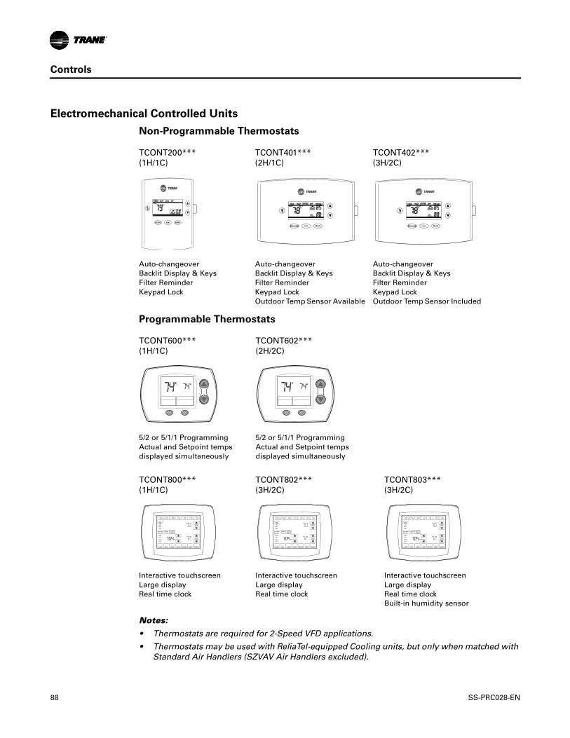
Controls
Electromechanical Controlled Units
Non-Programmable Thermostats
Programmable Thermostats
Notes:
• Thermostats are required for 2-Speed VFD applications.
• Thermostats may be used with ReliaTel-equipped Cooling units, but only when matched with Standard Air Handlers (SZVAV Air Handlers excluded).
TCONT200*** (1H/1C)
TCONT401*** (2H/1C)
TCONT402*** (3H/2C)
Auto-changeover Backlit Display & Keys Filter Reminder Keypad Lock
Auto-changeover Backlit Display & Keys Filter Reminder Keypad Lock Outdoor Temp Sensor Available
Auto-changeover Backlit Display & Keys Filter Reminder Keypad Lock Outdoor Temp Sensor Included
TCONT600*** (1H/1C)
TCONT602*** (2H/2C)
5/2 or 5/1/1 Programming Actual and Setpoint temps displayed simultaneously
5/2 or 5/1/1 Programming Actual and Setpoint temps displayed simultaneously
TCONT800*** (1H/1C)
TCONT802*** (3H/2C)
TCONT803*** (3H/2C)
Interactive touchscreen Large display Real time clock
Interactive touchscreen Large display Real time clock
Interactive touchscreen Large display Real time clock Built-in humidity sensor
$
FAN MODEFILTER
Fan ModeFilter/OD
$
Fan ModeFilter/OD
$
DONE WAKE LEAVE RETURN SLEEPEDIT CANCEL
MON TUE WED THU FRI SAT SUN
PM
FANON
AUTOCIRC
SYSTEMEM HEAT
HEATOFF
COOLAUTO
RESET
HEAT
COOL
DEHUMIDIFIERCANCELPERIOD
DONE WAKE LEAVE RETURN SLEEPEDIT CANCEL
MON TUE WED THU FRI SAT SUN
PM
FANON
AUTOCIRC
SYSTEMEM HEAT
HEATOFF
COOLAUTO
RESET
HEAT
COOL
DEHUMIDIFIERCANCELPERIOD
DONE WAKE LEAVE RETURN SLEEPEDIT CANCEL
MON TUE WED THU FRI SAT SUN
PM
FANON
AUTOCIRC
SYSTEMEM HEAT
HEATOFF
COOLAUTO
RESET
HEAT
COOL
DEHUMIDIFIERCANCELPERIOD
88 SS-PRC028-EN

Electrical Data
Condenser Electrical Data
Table 61. Electrical Characteristics — Compressor and Condenser Fan Motors —60 Hz
TonsUnit
Model No.
Compressor Motor Condenser Fan Motor
No. Volts Phase
Amps
No. Volts Phase
Amps
RLA LRA FLA LRA
(Ea.) (Ea.) (Ea.) (Ea.)
6
TTA073D3 1 208-230 3 22.4 149 1 208-230 1 3.1 8.1
TTA073D4 1 460 3 10.6 75 1 460 1 1.6 3.8
TTA073DK 1 380 3 11.3 88 1 380 1 2.7 7
TTA073DW 1 575 3 7.9 54 1 575 1 1.2 3
7½
TTA090D3 1 208-230 3 25 164 1 208-230 1 3.1 8.1
TTA090D4 1 460 3 12.9 100 1 460 1 1.6 3.8
TTA090DK 1 380 3 14.3 94.3 1 380 1 2.7 7
TTA090DW 1 575 3 10.6 78 1 575 1 1.2 3
10
TTA120D3 1 208-230 3 30.1 225 1 208-230 1 5 14.4
TTA120D4 1 460 3 16.7 114 1 460 1 2.5 5.8
TTA120DK 1 380 3 19.8 140 1 380 1 3.4 7.8
TTA120DW 1 575 3 12.4 80 1 575 1 2 5.1
TTA120E3 2 208-230 3 16 110 1 208-230 1 5 14.4
TTA120E4 2 460 3 7.8 52 1 460 1 2.5 5.8
TTA120EK 2 380 3 10.4 65.6 1 380 1 3.4 7.8
TTA120EW 2 575 3 6 38.9 1 575 1 2 5.1
TTA120F3 2 208-230 3 17.6 123 1 208-230 1 5 14.4
TTA120F4 2 460 3 9.6 62 1 460 1 2.5 5.8
TTA120FW 2 575 3 6.1 40 1 575 1 2 5.1
12½
TTA150E3 2 208-230 3 22.4 149 1 208-230 1 5 14.4
TTA150E4 2 460 3 10.6 75 1 460 1 2.5 5.8
TTA150EK 2 380 3 11.3 88 1 380 1 3.4 7.8
TTA150EW 2 575 3 8.6 54 1 575 1 2 5.1
15
TTA180E3 2 208-230 3 25 164 2 208-230 1 5 14.4
TTA180E4 2 460 3 12.2 100 2 460 1 2.5 5.8
TTA180EK 2 380 3 14.3 94.3 2 380 1 3.4 7.8
TTA180EW 2 575 3 9.6 78 2 575 1 2 5.1
TTA180F3 2 208-230 3 25 164 2 208-230 1 5 14.4
TTA180F4 2 460 3 12.2 100 2 460 1 2.5 5.8
TTA180FK 2 380 3 14.3 94.3 2 380 1 3.4 7.8
TTA180FW 2 575 3 9.9 78 2 575 1 2 5.1
Continued on next page
SS-PRC028-EN 89

Electrical Data
20
TTA240E3 2 208-230 3 39.1 267 2 208-230 1 5 14.4
TTA240E4 2 460 3 18.6 142 2 460 1 2.5 5.8
TTA240EK 2 380 3 23.1 160 2 380 1 3.4 7.8
TTA240EW 2 575 3 15.4 103 2 575 1 2 5.1
TTA240F3 2 208-230 3 39.1 267 2 208-230 1 5 14.4
TTA240F4 2 460 3 19.8 142 2 460 1 2.5 5.8
TTA240FK 2 380 3 23.1 160 2 380 1 3.4 7.8
TTA240FW 2 575 3 15.8 103 2 575 1 2 5.1
25
TTA300F3 2 208-230 3 53.6 245 2 208-230 1 5 14.4
TTA300F4 2 460 3 20.7 125 2 460 1 2.5 5.8
TTA300FK 2 380 3 26.4 145 2 380 1 3.4 7.8
TTA300FW 2 575 3 16.4 100 2 575 1 2 5.1
Note: Electrical characteristics reflect nameplate values and are calculated in accordance with cULus and ARI specifications.
Table 61. Electrical Characteristics — Compressor and Condenser Fan Motors —60 Hz (continued)
TonsUnit
Model No.
Compressor Motor Condenser Fan Motor
No. Volts Phase
Amps
No. Volts Phase
Amps
RLA LRA FLA LRA
(Ea.) (Ea.) (Ea.) (Ea.)
Table 62. Unit Wiring — Condensing Units — 60 Hz
Tons Unit Model NumberUnit Operating Voltage Range
Minimum Circuit Ampacity
Maximum Fuse or HACR Circuit Breaker
Size(a)
6
TTA073D3 187-253 31.1 40
TTA073D4 414-506 14.9 20
TTA073DK 342-418 16.8 20
TTA073DW 518-632 11.1 15
7½
TTA090D3 187-253 34.4 45
TTA090D4 414-506 17.7 25
TTA090DK 342-418 20.6 25
TTA090DW 518-632 14.5 20
10
TTA120D3 187-253 42.6 60
TTA120D4 414-506 23.4 30
TTA120DK 342-418 28.2 35
TTA120DW 518-632 17.5 25
TTA120E3 187-253 41.0 45
TTA120E4 414-506 20.1 25
TTA120EK 342-418 26.9 30
TTA120EW 518-632 15.5 20
TTA120F3 187-253 44.6 50
TTA120F4 414-506 24.1 30
TTA120FW 518-632 15.7 20
12½
TTA150E3 187-253 55.4 70
TTA150E4 414-506 26.4 30
TTA150EK 342-418 28.8 35
TTA150EW 518-632 21.4 25
Continued on next page
90 SS-PRC028-EN
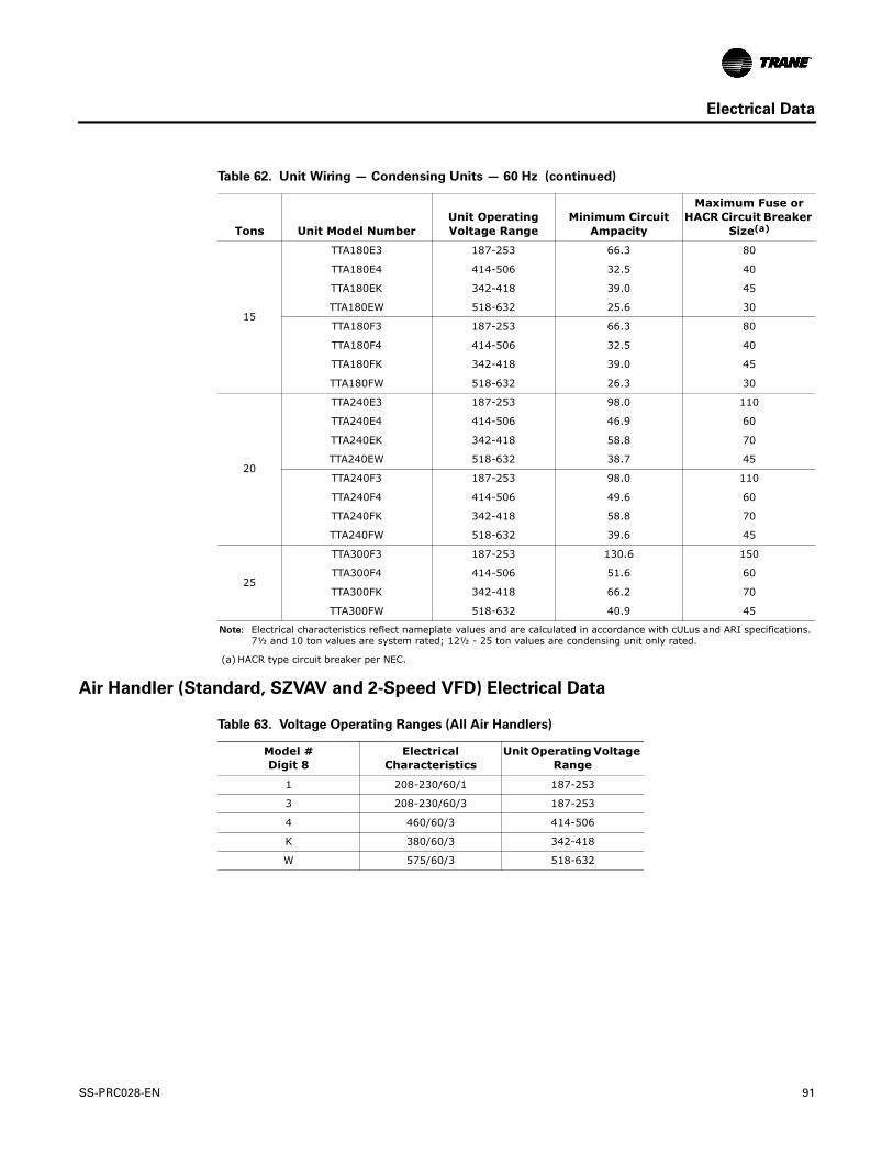
Electrical Data
Air Handler (Standard, SZVAV and 2-Speed VFD) Electrical Data
15
TTA180E3 187-253 66.3 80
TTA180E4 414-506 32.5 40
TTA180EK 342-418 39.0 45
TTA180EW 518-632 25.6 30
TTA180F3 187-253 66.3 80
TTA180F4 414-506 32.5 40
TTA180FK 342-418 39.0 45
TTA180FW 518-632 26.3 30
20
TTA240E3 187-253 98.0 110
TTA240E4 414-506 46.9 60
TTA240EK 342-418 58.8 70
TTA240EW 518-632 38.7 45
TTA240F3 187-253 98.0 110
TTA240F4 414-506 49.6 60
TTA240FK 342-418 58.8 70
TTA240FW 518-632 39.6 45
25
TTA300F3 187-253 130.6 150
TTA300F4 414-506 51.6 60
TTA300FK 342-418 66.2 70
TTA300FW 518-632 40.9 45
Note: Electrical characteristics reflect nameplate values and are calculated in accordance with cULus and ARI specifications. 7½ and 10 ton values are system rated; 12½ - 25 ton values are condensing unit only rated.
(a) HACR type circuit breaker per NEC.
Table 62. Unit Wiring — Condensing Units — 60 Hz (continued)
Tons Unit Model NumberUnit Operating Voltage Range
Minimum Circuit Ampacity
Maximum Fuse or HACR Circuit Breaker
Size(a)
Table 63. Voltage Operating Ranges (All Air Handlers)
Model # Digit 8
Electrical Characteristics
Unit Operating Voltage Range
1 208-230/60/1 187-253
3 208-230/60/3 187-253
4 460/60/3 414-506
K 380/60/3 342-418
W 575/60/3 518-632
SS-PRC028-EN 91

Electrical Data
Table 64. Electrical Characteristics — Standard and Low Static Motors — 60 Hz Standard Air Handler(a)
Tons Unit Model Number
Standard Evaporator Fan Motor Low Static Evaporator Fan Motor
No. Volts Phase Hp
Amps
MCA MFS No. Volts Phase Hp
Amps
MCA MFSFLA LRA FLA LRA
5
TWE061D1, E1 1 208 1 0.75 6.0 41.0 7.5 15 N/A N/A N/A N/A N/A N/A N/A N/A
TWE061D1, E1 1 230 1 0.75 5.9 45.0 7.4 15 N/A N/A N/A N/A N/A N/A N/A N/A
TWE061D3, E3 1 208 3 0.75 2.5 16.4 3.1 15 N/A N/A N/A N/A N/A N/A N/A N/A
TWE061D3, E3 1 230 3 0.75 2.4 16.4 3.0 15 N/A N/A N/A N/A N/A N/A N/A N/A
TWE061D4, E4 1 460 3 0.75 1.2 8.2 1.5 15 N/A N/A N/A N/A N/A N/A N/A N/A
TWE061DW 1 575 3 0.75 1.3 6.1 1.6 15 N/A N/A N/A N/A N/A N/A N/A N/A
7½
TWE090D1, E1 1 208 1 1.50 6.8 31.5 8.5 20 N/A N/A N/A N/A N/A N/A N/A N/A
TWE090D1, E1 1 230 1 1.50 6.2 31.5 7.8 15 N/A N/A N/A N/A N/A N/A N/A N/A
TWE090D3, E3 1 208 3 1.50 5.3 34.3 6.6 15 N/A N/A N/A N/A N/A N/A N/A N/A
TWE090D3, E3 1 230 3 1.50 5.0 34.3 6.3 15 N/A N/A N/A N/A N/A N/A N/A N/A
TWE090D3, E3(b) 1 460 3 1.50 2.5 17.0 3.1 15 N/A N/A N/A N/A N/A N/A N/A N/A
TWE090DW 1 575 3 1.50 1.8 13.6 2.3 15 N/A N/A N/A N/A N/A N/A N/A N/A
10
TWE120D1, E1 1 208 1 2.00 8.5 57.4 10.6 20 N/A N/A N/A N/A N/A N/A N/A N/A
TWE120D1, E1 1 230 1 2.00 7.7 57.4 9.6 20 N/A N/A N/A N/A N/A N/A N/A N/A
TWE120D3, E3 1 208 3 2.00 7.0 33.9 7.8 15 N/A N/A N/A N/A N/A N/A N/A N/A
TWE120D3, E3 1 230 3 2.00 6.6 33.9 7.3 15 N/A N/A N/A N/A N/A N/A N/A N/A
TWE120D3, E3(b) 1 460 3 2.00 3.3 19.0 3.6 15 N/A N/A N/A N/A N/A N/A N/A N/A
TWE120DW, EW 1 575 3 2.00 2.3 15.6 4.0 15 N/A N/A N/A N/A N/A N/A N/A N/A
12½
TWE150E3 1 208 3 2.00 5.95 23.0 7.4 15 N/A N/A N/A N/A N/A N/A N/A N/A
TWE150E3 1 230 3 2.00 5.5 23.0 6.9 15 N/A N/A N/A N/A N/A N/A N/A N/A
TWE150E3(b) 1 460 3 2.00 2.75 23.0 3.4 15 N/A N/A N/A N/A N/A N/A N/A N/A
TWE150EW 1 575 3 2.00 2.2 18.0 2.8 15 N/A N/A N/A N/A N/A N/A N/A N/A
15
TWE180E3 1 208 3 3.00 9.4 74.9 11.8 25 N/A N/A N/A N/A N/A N/A N/A N/A
TWE180E3 1 230 3 3.00 9.2 74.9 11.5 25 N/A N/A N/A N/A N/A N/A N/A N/A
TWE180E3(b) 1 460 3 3.00 4.6 39.3 5.8 15 N/A N/A N/A N/A N/A N/A N/A N/A
TWE180EW 1 575 3 3.00 3.4 24.6 4.3 15 N/A N/A N/A N/A N/A N/A N/A N/A
20
TWE240E3 1 208 3 5.00 14.0 90.8 17.5 25 1 208 3 3.00 9.4 74.9 11.8 25
TWE240E3 1 230 3 5.00 13.6 103.0 17.0 25 1 230 3 3.00 9.2 74.9 11.5 25
TWE240E4 1 460 3 5.00 6.6 44.8 9.0 15 1 460 3 3.00 4.6 39.3 5.8 15
TWE240EW 1 575 3 5.00 5.3 36.2 6.6 15 1 575 3 3.00 3.4 24.6 4.3 15
25
TWE300E3 1 208 3 7.50 19.6 150 25 40 N/A N/A N/A N/A N/A N/A N/A N/A
TWE300E3 1 230 3 7.50 17.8 150 25 40 N/A N/A N/A N/A N/A N/A N/A N/A
TWE300E4 1 460 3 7.50 8.9 75 12 20 N/A N/A N/A N/A N/A N/A N/A N/A
TWE300EW 1 575 3 7.50 7.1 60 9 15 N/A N/A N/A N/A N/A N/A N/A N/A
(a) For additional information contact product support.(b) Field wired for 460V.
92 SS-PRC028-EN

Electrical Data
Table 65. Electrical Characteristics — Standard and Oversized Motors — 60 Hz SZVAV and 2-Speed VFD Air Handler(a)
TonsUnit Model
Number
Standard Evaporator Fan Motor Oversized Evaporator Fan Motor
Amps Amps
No Volts Phase HP FLA LRA MCA MFS No Volts Phase HP FLA LRA MCA MFS
10
TWE120D3, E3 1 208 3 2 6.2 43.4 8 15 1 208 3 3 9.4 71 12 20
TWE120D3, E3 1 230 3 2 5.8 48 8 15 1 230 3 3 9.2 64 12 20
TWE120D4, E4 1 460 3 2 2.9 24 4 15 1 460 3 3 4.6 35.5 6 15
TWE120DW, EW 1 575 3 2 2.2 20.6 3 15 1 575 3 3 3.7 28.4 5 15
12½
TWE150E3 1 208 3 2 6.2 43.4 8 15 1 208 3 5 13.4 99.5 17 30
TWE150E3 1 230 3 2 5.8 48 8 15 1 230 3 5 12.6 110 17 30
TWE150E4 1 460 3 2 2.9 24 4 15 1 460 3 5 6.3 55 8 15
TWE150EW 1 575 3 2 2.2 20.6 3 15 1 575 3 5 5.1 44 7 15
15
TWE180E3 1 208 3 3 9.4 71 12 20 1 208 3 5 13.4 99.5 17 30
TWE180E3 1 230 3 3 9.2 64 12 20 1 230 3 5 12.6 110 17 30
TWE180E4 1 460 3 3 4.6 35.5 6 15 1 460 3 5 6.3 55 8 15
TWE180EW 1 575 3 3 3.7 28.4 5 15 1 575 3 5 5.1 44 7 15
20
TWE240E3 1 208 3 5 13.4 99.5 17 30 1 208 3 7.5 20 113.4 25 45
TWE240E3 1 230 3 5 12.6 110 17 30 1 230 3 7.5 17.6 124 25 45
TWE240E4 1 460 3 5 6.3 55 8 15 1 460 3 7.5 8.8 63 11 15
TWE240EW 1 575 3 5 5.1 44 7 15 1 575 3 7.5 7.1 50.4 9 15
25
TWE300E3 1 208 3 7.5 20 113.4 25 45 N/A N/A N/A N/A N/A N/A N/A N/A
TWE300E3 1 230 3 7.5 17.6 124 25 45 N/A N/A N/A N/A N/A N/A N/A N/A
TWE300E4 1 460 3 7.5 8.8 63 12 20 N/A N/A N/A N/A N/A N/A N/A N/A
TWE300EW 1 575 3 7.5 7.1 50.4 9 15 N/A N/A N/A N/A N/A N/A N/A N/A
(a) For additional information contact product support.
SS-PRC028-EN 93

Electrical Data
Table 66. Electrical Characteristics — High and Ultra-High Static Motors — 60 Hz Standard Air Handler(a)
Tons Unit Model Number
High Static Evaporator Fan Motor Ultra-High Static Evaporator Fan Motor
No. Volts Phase Hp
Amps
MCA MFS No. Volts Phase Hp
Amps
MCA MFSFLA LRA FLA LRA
5
TWE061D1, E1 1 208 1 1.50 6.8 31.5 8.5 20 N/A N/A N/A N/A N/A N/A N/A N/A
TWE061D1, E1 1 230 1 1.50 6.2 31.5 7.8 15 N/A N/A N/A N/A N/A N/A N/A N/A
TWE061D3, E3 1 208 3 1.50 5.3 34.3 6.6 15 N/A N/A N/A N/A N/A N/A N/A N/A
TWE061D3, E3 1 230 3 1.50 5.0 34.3 6.3 15 N/A N/A N/A N/A N/A N/A N/A N/A
TWE061D4, E4 1 460 3 1.50 2.5 17.0 3.1 15 N/A N/A N/A N/A N/A N/A N/A N/A
TWE061DW 1 575 3 1.50 1.8 13.6 2.3 15 N/A N/A N/A N/A N/A N/A N/A N/A
7½
TWE090D1, E1 1 208 1 2.00 8.5 57.4 10.6 20 N/A N/A N/A N/A N/A N/A N/A N/A
TWE090D1, E1 1 230 1 2.00 7.7 57.4 9.6 20 N/A N/A N/A N/A N/A N/A N/A N/A
TWE090D3, E3 1 208 3 2.00 7.0 33.9 7.8 15 1 208 3 3.00 9.4 74.9 11.8 25
TWE090D3, E3 1 230 3 2.00 6.6 33.9 7.3 15 1 230 3 3.00 9.2 74.9 11.5 25
TWE090D3, E3(b) 1 460 3 2.00 3.3 19.0 3.6 15 1 460 3 3.00 4.6 39.3 5.8 15
TWE090DW 1 575 3 2.00 2.3 15.6 4.0 15 1 575 3 3.00 3.4 24.6 4.3 15
10
TWE120D1, E1 N/A N/A N/A N/A N/A N/A N/A N/A N/A N/A N/A N/A N/A N/A N/A N/A
TWE120D1, E1 N/A N/A N/A N/A N/A N/A N/A N/A N/A N/A N/A N/A N/A N/A N/A N/A
TWE120D3, E3 1 208 3 3.00 9.4 74.9 11.8 25 N/A N/A N/A N/A N/A N/A N/A N/A
TWE120D3, E3 1 230 3 3.00 9.2 74.9 11.5 25 N/A N/A N/A N/A N/A N/A N/A N/A
TWE120D3, E3(b) 1 460 3 3.00 4.6 39.3 5.8 15 N/A N/A N/A N/A N/A N/A N/A N/A
TWE120DW, EW 1 575 3 3.00 3.4 24.6 4.3 15 N/A N/A N/A N/A N/A N/A N/A N/A
12½
TWE150E3 1 208 3 3.00 9.4 74.9 11.8 25 1 208 3 5.00 14.0 98.0 17.5 35
TWE150E3 1 230 3 3.00 9.2 74.9 11.5 25 1 230 3 5.00 13.6 103.0 17 35
TWE150E3(b) 1 460 3 3.00 4.6 39.3 5.8 15 1 460 3 5.00 6.6 44.8 8.3 20
TWE150EW 1 575 3 3.00 3.4 24.6 4.3 15 1 575 3 5.00 5.2 36.2 6.5 15
15
TWE180E3 1 208 3 5.00 14.0 98.0 17.5 35 N/A N/A N/A N/A N/A N/A N/A N/A
TWE180E3 1 230 3 5.00 13.6 103.0 17 35 N/A N/A N/A N/A N/A N/A N/A N/A
TWE180E3(b) 1 460 3 5.00 6.6 44.8 8.3 15 N/A N/A N/A N/A N/A N/A N/A N/A
TWE180EW 1 575 3 5.00 5.2 36.2 6.5 15 N/A N/A N/A N/A N/A N/A N/A N/A
20
TWE240E3 N/A N/A N/A N/A N/A N/A N/A N/A 1 208 3 7.50 20 114.0 25.0 45
TWE240E3 N/A N/A N/A N/A N/A N/A N/A N/A 1 230 3 7.50 17.6 126.0 22.0 40
TWE240E4 N/A N/A N/A N/A N/A N/A N/A N/A 1 460 3 7.50 9.0 61.4 11.3 25
TWE240EW N/A N/A N/A N/A N/A N/A N/A N/A 1 575 3 7.50 7.2 49.8 9.0 20
25
TWE300E3 N/A N/A N/A N/A N/A N/A N/A N/A N/A N/A N/A N/A N/A N/A N/A N/A
TWE300E3 N/A N/A N/A N/A N/A N/A N/A N/A N/A N/A N/A N/A N/A N/A N/A N/A
TWE300E4 N/A N/A N/A N/A N/A N/A N/A N/A N/A N/A N/A N/A N/A N/A N/A N/A
TWE300EW N/A N/A N/A N/A N/A N/A N/A N/A N/A N/A N/A N/A N/A N/A N/A N/A
(a) For additional information contact product support.(b) Field wired for 460V.
94 SS-PRC028-EN

Electrical Data
Table 67. Unit Wiring with Electric Heat (Single Point Connection) — 5-10 Ton Standard Air Handlers — 60 Hz
Tons Used With Heater Model
No. Heater KW Rating(a)
Unit Power Supply Control Stages
Minimum Circuit
Ampacity(b)
Maximum Fuse or HACR
Circuit Breaker Size(b)(c)
5 TWE061D1 TWE061E1
BAYHTRL106A 4.33/5.76
208-230/1/60
1 33.5/37.4 35/40
BAYHTRL112A 8.65/11.52 1 59.5/67.4 60/70
BAYHTRL117A 12.98/17.28 1 85.5/97.4 90/100
BAYHTRL123A 17.31/23.04 2 111.5/127.4(d) 125/150
7½ TWE090D1 TWE090E1
BAYHTRL106A 4.33/5.76 1 34.5/37.8 40/40
BAYHTRL112A 8.65/11.52 1 60.5/67.8(d) 70/70
BAYHTRL117A 12.98/17.28 1 86.5/97.8 90/100
BAYHTRL123A 17.31/23.04 2 112.5/127.8(d) 125/150
BAYHTRL129A 21.63/28.80 2 138.6/157.8(d) 150/175
10TWE120D1 TWE120E1
BAYHTRL106A 4.33/5.76 1 36.6/39.6 40/45
BAYHTRL112A 8.65/11.52 1 62.6/69.6(d) 70/70
BAYHTRL117A 12.98/17.28 1 88.6/99.6 90/100
BAYHTRL123A 17.31/23.04 2 114.6/129.6(d) 125/150
BAYHTRL129A 21.63/28.80 2 140.7/159.6(d) 150/175
5 TWE061D3 TWE061E3
BAYHTRL305A 3.76/5.00
208-230/3/60
1 16.1/18 20/20
BAYHTRL310A 7.48/9.96 1 29/33 30/35
BAYHTRL315A 11.24/14.96 1 42.2/48 45/50
BAYHTRL325A 18.72/24.92 2 68/77.9(d) 70/80
7½ TWE090D3 TWE090E3
BAYHTRL305A 3.76/5.00 1 19.6/21.3 25/25
BAYHTRL310A 7.48/9.96 1 32.5/36.2 35/40
BAYHTRL315A 11.24/14.96 1 45.7/51.2 50/60
BAYHTRL325A 18.72/24.92 2 71.5/82(d) 80/90
BAYHTRL335A 26.20/34.88 2 98.7/112(e) 100/125
10 TWE120D3 TWE120E3
BAYHTRL305A 3.76/5.00 1 21/23 25/30
BAYHTRL310A 7.48/9.96 1 34/38 35/40
BAYHTRL315A 11.24/14.96 1 47/53 50/60
BAYHTRL325A 18.72/24.92 2 73/83(d) 80/90
BAYHTRL335A 26.20/34.88 2 98.7/113(e) 100/125
continued on next page
SS-PRC028-EN 95

Electrical Data
5 TWE061D4 TWE061E4
BAYHTRL405A 5
460/3/60
1 10 15
BAYHTRL410A 9.96 1 17 20
BAYHTRL415A 14.96 1 25 25
BAYHTRL425A 24.92 2 40 40
7½ TWE090D3(f) TWE090E3(f)
BAYHTRL405A 5 1 11 15
BAYHTRL410A 9.96 1 19 20
BAYHTRL415A 14.96 1 26 30
BAYHTRL425A 24.92 2 41 45
BAYHTRL435A 34.88 2 56 60
10 TWE120D3(f) TWE120E3(f)
BAYHTRL405A 5 1 12 15
BAYHTRL410A 9.96 1 20 20
BAYHTRL415A 14.96 1 27 30
BAYHTRL425A 24.92 2 42 45
BAYHTRL435A 34.88 2 57 60
5 TWE061DW
BAYHTRLW05A 5
575/3/60
1 8 15
BAYHTRLW10A 9.96 1 15 15
BAYHTRLW15A 14.96 1 21 20
BAYHTRLW25A 24.92 2 33 35
7½ TWE090DW
BAYHTRLW05A 5 1 11 15
BAYHTRLW10A 9.96 1 17 15
BAYHTRLW15A 14.96 1 23 25
BAYHTRLW25A 24.92 2 36 35
BAYHTRLW35A 34.88 2 48 45
10 TWE120DW TWE120EW
BAYHTRLW05A 5 1 10 15
BAYHTRLW10A 9.96 1 16 15
BAYHTRLW15A 14.96 1 22 25
BAYHTRLW25A 24.92 2 35 35
BAYHTRLW35A 34.88 2 47 45
(a) kW ratings are at: 208/240V for 208-230V air handlers.480V for 460V air handlers600V for 575V air handlersFor other than rated voltage, capacity = (Voltage/Rated Voltage)2 x Rated Capacity.
(b) Any power supply and circuits must be wired and protected in accordance with local codes.(c) The HACR circuit breaker is for U.S.A. installations only.(d) Field wire must be rated at least 75°C.(e) Field wire must be rated at least 90°C.(f) With motor field converted to 460V.
Table 67. Unit Wiring with Electric Heat (Single Point Connection) — 5-10 Ton Standard Air Handlers — 60 Hz (continued)
Tons Used With Heater Model
No. Heater KW Rating(a)
Unit Power Supply Control Stages
Minimum Circuit
Ampacity(b)
Maximum Fuse or HACR
Circuit Breaker Size(b)(c)
96 SS-PRC028-EN

Electrical Data
Table 68. Unit Wiring with Electric Heat (Single Point Connection) — 10 Ton SZVAV and 2-Speed VFD Air Handlers — 60 Hz
Tons Used WithHeater
Model No.Heater KW Rating(a)
Unit Power Supply
Control Stages
Minimum Circuit
Ampacity(b)
Maximum Fuse or HACR
Circuit Breaker Size(b)(c)
10
TWE120D3*3, E3*3
BAYHTRL305A 3.76/5.00
208-230/3/60
1 21/23 25/25
BAYHTRL310A 7.48/9.96 1 34/38 35/40
BAYHTRL315A 11.24/14.96 1 47/53 50/60
BAYHTRL325A 18.72/24.92 2 73/83 80/90
BAYHTRL335A 26.20/34.88 2 99/113 100/125
TWE120D3*4, E3*4
BAYHTRL305A 3.76/5.00 1 25/27 30/30
BAYHTRL310A 7.48/9.96 1 38/42 40/45
BAYHTRL315A 11.24/14.96 1 38/57 40/60
BAYHTRL325A 18.72/24.92 2 77/87 80/90
BAYHTRL335A 26.20/34.88 2 103/117 110/125
TWE120D4*3, E4*3
BAYHTRL405A 5
460/3/60
1 12 15
BAYHTRL410A 9.96 1 19 20
BAYHTRL415A 14.96 1 27 30
BAYHTRL425A 24.92 2 42 45
BAYHTRL435A 34.88 2 57 60
TWE120D4*4, E4*4
BAYHTRL405A 5 1 14 15
BAYHTRL410A 9.96 1 21 25
BAYHTRL415A 14.96 1 29 30
BAYHTRL425A 24.92 2 44 45
BAYHTRL435A 34.88 2 59 60
TWE120DW*3, EW*3
BAYHTRLW05A 5
575/3/60
1 9 15
BAYHTRLW10A 9.96 1 16 20
BAYHTRLW15A 14.96 1 22 25
BAYHTRLW25A 24.92 2 34 35
BAYHTRLW35A 34.88 2 47 50
TWE120DW*4, EW*4
BAYHTRLW05A 5 1 11 15
BAYHTRLW10A 9.96 1 18 20
BAYHTRLW15A 14.96 1 24 25
BAYHTRLW25A 24.92 2 36 40
BAYHTRLW35A 34.88 2 49 50
(a) kW ratings are at: 208/240V for 208-230V air handlers.480V for 460V air handlers600V for 575V air handlersFor other than rated voltage, capacity = (Voltage/Rated Voltage)2 x Rated Capacity.
(b) Any power supply and circuits must be wired and protected in accordance with local codes.(c) The HACR circuit breaker is for U.S.A. installations only.
SS-PRC028-EN 97

Electrical Data
Table 69. Unit Wiring with Electric Heat (Single Point Connection) — 12½ - 25 Ton Standard Air Handlers
Tons Used WithHeater
Model No.Heater KW Rating(a)
Unit Power Supply
Control Stages
Minimum Circuit Ampacity(b)
Maximum Fuse or HACR Circuit
Breaker Size(b)(c)
12½ TWE150E3
BAYHTRM310A 7.51/10.00
208-230/3/60
1 33.5/36.9 35/40
BAYHTRM320A 14.96/19.92 1 59.3/66.8 60/70
BAYHTRM330A 22.47/29.92 2 85.5/96.8 90/100
BAYHTRM350A 37.44/49.84 2 137.3/156.7 150/175
15 TWE180E3
BAYHTRM310A 7.51/10.00 1 37.8/41.6 45/45
BAYHTRM320A 14.96/19.92 1 63.7/71.4 70/80
BAYHTRM330A 22.47/29.92 2 89.8/101.5 90/110
BAYHTRM350A 37.44/49.84 2 141.6/161.4(d) 150/175
20 TWE240E3
BAYHTRM310A 7.51/10.00 1 44.1/49 60/60
BAYHTRM320A 14.96/19.92 1 71/79 80/90
BAYHTRM330A 22.47/29.92 2 97/109 100/110
BAYHTRM350A 37.44/49.84 2 149/169(d) 150/175
25 TWE300E3
BAYHTRM310A 7.51/10 1 51/53 60/90
BAYHTRM320A 14.96/19.92 1 77/83 85/90
BAYHTRM330A 22.47/29.92 2 103/113 110/125
BAYHTRM350A 37.44/49.84 2 155/173 175/175
12½ TWE150E3(e)
BAYHTRM410A 10
460/3/60
1 19 20
BAYHTRM420A 19.92 1 34 35
BAYHTRM430A 29.92 2 49 50
BAYHTRM450A 49.84 2 79 80
15 TWE180E3(e)
BAYHTRM410A 10 1 21 25
BAYHTRM420A 19.92 1 36 40
BAYHTRM430A 29.92 2 51 60
BAYHTRM450A 49.84 2 81 90
20 TWE240E4
BAYHTRM410A 10 1 24 30
BAYHTRM420A 19.92 1 39 40
BAYHTRM430A 29.92 2 54 60
BAYHTRM450A 49.84 2 84 90
25 TWE300E4
BAYHTRM410A 10 1 27 30
BAYHTRM420A 19.92 1 42 45
BAYHTRM430A 29.92 2 57 60
BAYHTRM450A 49.84 2 87 90
98 SS-PRC028-EN

Electrical Data
12½ TWE150EW
BAYHTRMW10A 10
575/3/60
1 15 15
BAYHTRMW20A 19.92 1 27 30
BAYHTRMW30A 29.92 2 39 40
BAYHTRMW50A 49.84 2 63 70
15 TWE180EW
BAYHTRMW10A 10 1 17 20
BAYHTRMW20A 19.92 1 30 30
BAYHTRMW30A 29.92 2 42 45
BAYHTRMW50A 49.84 2 67 70
20 TWE240EW
BAYHTRMW10A 10 1 20 25
BAYHTRMW20A 19.92 1 32 35
BAYHTRMW30A 29.92 2 45 45
BAYHTRMW50A 49.84 2 70 70
25 TWE300EW
BAYHTRMW10A 10 1 22 25
BAYHTRMW20A 19.92 1 34 35
BAYHTRMW30A 29.92 2 47 50
BAYHTRMW50A 49.84 2 72 80
(a) kW ratings are at: 208/240V for 208-230V air handlers.480V for 460V air handlers600V for 575V air handlersFor other than rated voltage, capacity = (Voltage/Rated Voltage)2 x Rated Capacity.
(b) Any power supply and circuits must be wired and protected in accordance with local codes.(c) The HACR circuit breaker is for U.S.A. installations only.(d) Field wire must be rated at least 90°C.(e) With motor field wired for 460V.
Table 69. Unit Wiring with Electric Heat (Single Point Connection) — 12½ - 25 Ton Standard Air Handlers
SS-PRC028-EN 99

Electrical Data
Table 70. Unit Wiring with Electric Heat (Single Point Connection) — 12½ - 25 Ton SZVAV and 2-Speed VFD Air Handlers
Tons Used WithHeater
Model No.Heater KW Rating(a)
Unit Power Supply
Control Stages
Minimum Circuit
Ampacity(b)
Maximum Fuse or HACR Circuit
Breaker Size(b)(c)
12½
TWE150E3*3
BAYHTRM310A 7.51/10.00
208-230/3/60
1 34/38 35/40
BAYHTRM320A 14.96/19.92 1 60/68 60/70
BAYHTRM330A 22.47/29.92 2 86/98 90/100
BAYHTRM350A 37.44/49.84 2 138/158 150/175
TWE150E3*4
BAYHTRM310A 7.51/10.00 1 43/47 45/50
BAYHTRM320A 14.96/19.92 1 69/77 70/80
BAYHTRM330A 22.47/29.92 2 95/107 100/110
BAYHTRM350A 37.44/49.84 2 147/167 150/175
TWE150E4*3
BAYHTRM410A 10
460/3/60
1 19 20
BAYHTRM420A 19.92 1 34 35
BAYHTRM430A 29.92 2 49 50
BAYHTRM450A 49.84 2 79 80
TWE150E4*4
BAYHTRM410A 10 1 23 25
BAYHTRM420A 19.92 1 38 40
BAYHTRM430A 29.92 2 53 60
BAYHTRM450A 49.84 2 83 90
TWE150EW*3
BAYHTRMW10A 10
575/3/60
1 16 20
BAYHTRMW20A 19.92 1 28 30
BAYHTRMW30A 29.92 2 41 45
BAYHTRMW50A 49.84 2 66 70
TWE150EW*4
BAYHTRMW10A 10 1 19 20
BAYHTRMW20A 19.92 1 32 35
BAYHTRMW30A 29.92 2 44 45
BAYHTRMW50A 49.84 2 69 70
continued on next page
100 SS-PRC028-EN

Electrical Data
15
TWE180E3*3
BAYHTRM310A 7.51/10.00
208-230/3/60
1 38/42 40/45
BAYHTRM320A 14.96/19.92 1 64/72 70/80
BAYHTRM330A 22.47/29.92 2 90/102 90/110
BAYHTRM350A 37.44/49.84 2 142/162 150/175
TWE180E3*4
BAYHTRM310A 7.51/10.00 1 43/47 45/50
BAYHTRM320A 14.96/19.92 1 69/77 70/80
BAYHTRM330A 22.47/29.92 2 95/107 100/110
BAYHTRM350A 37.44/49.84 2 147/167 150/175
TWE180E4*3
BAYHTRM410A 10
460/3/60
1 21 25
BAYHTRM420A 19.92 1 36 40
BAYHTRM430A 29.92 2 51 60
BAYHTRM450A 49.84 2 81 90
TWE180E4*4
BAYHTRM410A 10 1 23 25
BAYHTRM420A 19.92 1 38 40
BAYHTRM430A 29.92 2 53 60
BAYHTRM450A 49.84 2 83 90
TWE180EW*3
BAYHTRMW10A 10
575/3/60
1 18 20
BAYHTRMW20A 19.92 1 30 30
BAYHTRMW30A 29.92 2 43 45
BAYHTRMW50A 49.84 2 68 70
TWE180EW*4
BAYHTRMW10A 10 1 19 20
BAYHTRMW20A 19.92 1 32 35
BAYHTRMW30A 29.92 2 44 45
BAYHTRMW50A 49.84 2 69 70
continued on next page
Table 70. Unit Wiring with Electric Heat (Single Point Connection) — 12½ - 25 Ton SZVAV and 2-Speed VFD Air Handlers
Tons Used WithHeater
Model No.Heater KW Rating(a)
Unit Power Supply
Control Stages
Minimum Circuit
Ampacity(b)
Maximum Fuse or HACR Circuit
Breaker Size(b)(c)
SS-PRC028-EN 101

Electrical Data
20
TWE240E3*3
BAYHTRM310A 7.51/10.00
208-230/3/60
1 43/47 45/50
BAYHTRM320A 14.96/19.92 1 69/77 70/80
BAYHTRM330A 22.47/29.92 2 95/107 100/110
BAYHTRM350A 37.44/49.84 2 147/167 150/175
TWE240E3*4
BAYHTRM310A 7.51/10.00 1 51/55 60/60
BAYHTRM320A 14.96/19.92 1 77/85 80/90
BAYHTRM330A 22.47/29.92 2 103/115 110/125
BAYHTRM350A 37.44/49.84 2 155/175 175/175
TWE240E4*3
BAYHTRM410A 10
460/3/60
1 23 25
BAYHTRM420A 19.92 1 38 40
BAYHTRM430A 29.92 2 53 60
BAYHTRM450A 49.84 2 83 90
TWE240E4*4
BAYHTRM410A 10 1 26 30
BAYHTRM420A 19.92 1 41 45
BAYHTRM430A 29.92 2 56 60
BAYHTRM450A 49.84 2 86 90
TWE240EW*3
BAYHTRMW10A 10
575/3/60
1 19 20
BAYHTRMW20A 19.92 1 32 35
BAYHTRMW30A 29.92 2 44 45
BAYHTRMW50A 49.84 2 69 70
TWE240EW*4
BAYHTRMW10A 10 1 22 25
BAYHTRMW20A 19.92 1 34 35
BAYHTRMW30A 29.92 2 47 50
BAYHTRMW50A 49.84 2 72 80
25
TWE300E3*3
BAYHTRM310A 7.51/10.00
208-230/3/60
1 51/55 60/60
BAYHTRM320A 14.96/19.92 1 77/85 80/90
BAYHTRM330A 22.47/29.92 2 103/115 110/125
BAYHTRM350A 37.44/49.84 2 155/175 175/175
TWE300E4*3
BAYHTRM410A 10
460/3/60
1 26 30
BAYHTRM420A 19.92 1 41 45
BAYHTRM430A 29.92 2 56 60
BAYHTRM450A 49.84 2 86 90
TWE300EW*3
BAYHTRMW10A 10
575/3/60
1 22 25
BAYHTRMW20A 19.92 1 34 35
BAYHTRMW30A 29.92 2 47 50
BAYHTRMW50A 49.84 2 72 80
(a) kW ratings are at: 208/240V for 208-230V air handlers.480V for 460V air handlers600V for 575V air handlersFor other than rated voltage, capacity = (Voltage/Rated Voltage)2 x Rated Capacity.
(b) Any power supply and circuits must be wired and protected in accordance with local codes.(c) The HACR circuit breaker is for U.S.A. installations only.
Table 70. Unit Wiring with Electric Heat (Single Point Connection) — 12½ - 25 Ton SZVAV and 2-Speed VFD Air Handlers
Tons Used WithHeater
Model No.Heater KW Rating(a)
Unit Power Supply
Control Stages
Minimum Circuit
Ampacity(b)
Maximum Fuse or HACR Circuit
Breaker Size(b)(c)
102 SS-PRC028-EN

Jobsite Connections
For Electromechanical Controls
Wiring shown with dashed lines is to be furnished and installed by the customer. All customer-supplied wiring must be copper only and must conform to NEC and local electrical codes. Codes may require line of sight between disconnect switch and unit.
Notes:
1. When electric heater accessory is used, single point power entry or dual point power entry is field optional. Single point power entry option is through electric heater only.
2. Dual or manifolded compressor Cooling units are paired with Standard, SZVAV or 2-Speed VFD air handlers. See table below.
Field Wiring:
A. 3 power wires. Line voltage for 3 phase (2 wires for single phase)
B. 3 power wires. Line voltage for 3 phase (2 wires for single phase)
C. Cooling only thermostat: 3 to 7 wires depending on stages of electric heat
D. 3 to 7 wires depending on type of outdoor unit(s)
TTA073D/TWE090D TTA120F/TWE120D TTA240E/TWE240ETTA090D/TWE090D TTA150E/TWE150E TTA240F/TWE240E(a)
TTA090D/TWE120D TTA180E/TWE180E TTA300F/TWE300E(a)
TTA120D/TWE120D TTA180F/TWE180E(a)
(a) Need to manifold the dual circuit indoor unit when connecting to a Manifolded outdoor unit.
TTA120E/TWE120E TTA180E/TWE240E
SS-PRC028-EN 103

Jobsite Connections
For ReliaTel™ Controls
Wiring shown with dashed lines is to be furnished and installed by the customer. All customer-supplied wiring must be copper only and must conform to NEC and local electrical codes. Codes may require line of sight between disconnect switch and unit.
Notes:
1. When electric heater accessory is used, single point power entry or dual point power entry is field optional. Single point power entry option is through electric heater only.
2. ***Choose only one of the following; Thermostat, Zone Sensor, or NSB Panel.
3. Cooling units are paired with Standard or SZVAV air handlers. See table below.
Field Wiring:
A. 3 power wires, line voltage for 3 phase, (2 power wires for single phase)
B. 3 power wires, line voltage for 3 phase, (2 power wires for single phase)
C. Cooling only thermostat: 3 to 7 wires depending on stages of electric heat
D. 3 to 7 wires depending on type of outdoor unit(s)
For SZVAV air handlers: 4 additional wires are required (2 of which require twisted pair or shielded wire) in order to make connections between ReliaTel boards in the condenser and air handler.
E. Zone Sensor: 4 to 10 wires depending on zone sensor model 1
F. Night Setback Panel: 7 wires
TTA073D/TWE090D TTA120F/TWE120D TTA240E/TWE240ETTA090D/TWE090D TTA150E/TWE150E TTA240F/TWE240E(a)
TTA090D/TWE120D TTA180E/TWE180E TTA300F/TWE300E(a)
TTA120D/TWE120D TTA180F/TWE180E(a)
(a) Need to manifold the dual circuit indoor unit when connecting to a manifolded outdoor unit.
TTA120E/TWE120E TTA180E/TWE240E
1 See Zone Sensor wiring instructions for wiring information (ReliaTel Controls only).
NSB PanelZone Sensor
T’stat
Air Handler
Disconnect Switch(By Others)
Disconnect Switch(By Others) Note 2
ElectricHeat Accessory
Disconnect Switch(By Others)
Note 2
B
A
B
D
FEC
104 SS-PRC028-EN

Jobsite Connections
This page intentionally left blank.
SS-PRC028-EN 105

Typical Wiring
Figure 19. Typical Single & Dual Compressor - Electromechanical Connection Diagram
106 SS-PRC028-EN

Typical Wiring
Figure 19. (continued from previous page) Typical Single & Dual Compressor - Electromechanical Connection Diagram
SS-PRC028-EN 107

Typical Wiring
Figure 20. Typical Single Compressor - Connection Diagram
108 SS-PRC028-EN

Typical Wiring
Figure 20. (continued from previous page) Typical Single Compressor - Connection Diagram
SS-PRC028-EN 109

Typical Wiring
Figure 21. Typical Dual Compressor - Connection Diagram
110 SS-PRC028-EN

Typical Wiring
Figure 21. (continued from previous page) Typical Dual Compressor - Connection Diagram
SS-PRC028-EN 111

Typical Wiring
Figure 22. Typical Power/Control Diagram (Single and Dual Compressor)
112 SS-PRC028-EN

Typical Wiring
Figure 22. (continued from previous page) Typical Power/Control Diagram (Single and Dual Compressor)
SS-PRC028-EN 113

Typical Wiring
Figure 23. Typical Standard Air Handler Power/Control and Connection Diagram
114 SS-PRC028-EN

Typical Wiring
Figure 23. (continued from previous page) Typical Air Handler Power/Control and Connection Diagram
SS-PRC028-EN 115

Dimensional Data
Figure 24. 6-7 1/2 Ton Condensing Unit, Single Compressor
BOTTOMOF UNIT
7 15/16"
16 7/16"
29 13/16"34 1/8"
14 3/8"
26 15/16"
39 3/16"
2 7/8"
1 7/8"
33 13/16"
1/16"
6"
21 11/16"
6"
34 3/4"40 3/4"
3"
1 13/16" 27 11/16" 2 5/16"
4 3/16"
33 7/8"
35 15/16"
40 15/16"
41 15/16"
NOTES:1. ACCESS OPENING IS FOR FIELD INSTALLED BAYLOAM ACCESSORY.2. MINIMUM CLEARANCE FOR PROPER OPERATION IS 36" FROM WALLS, SHRUBBERY, PRIVACY FENCES ETC. MINIMUM CLEARANCE BETWEEN ADJACENT UNITS IS 72". RECOMMENDED SERVICE CLEARANCE 48"3. TOP DISCHARGE AREA SHOULD BE UNRESTRICTED FOR 100" MINIMUM. UNIT SHOULD BE PLACED SO ROOF RUN-OFF WATER DOES NOT POUR DIRECTLY ON UNIT4. OUTDOOR AIR TEMPERATURE SENSOR OPENING (DO NOT BLOCK OPENING)
SERVICE CLEARANCE 48" (SEE NOTE 2FOR CLEARANCE) SEE NOTE 1
REFRIGERANT ACCESS
HAIL GUARD (OPTIONAL)
SUCTION LINE
LIQUID LINE
CONTROL WIRING
LINE VOLTAGE
SERVICE PANEL
HAIL GUARD (OPTIONAL)
SERVICE PANEL
7/16" DIA. ISOLATOR MOUNTING HOLES (OUTSIDE HOLES - 4 PLACES)
SEE NOTE 3
SERVICE PANEL SIDE
SEE NOTE 4
WITH HAIL GUARD
WITH HAIL GUARD
116 SS-PRC028-EN
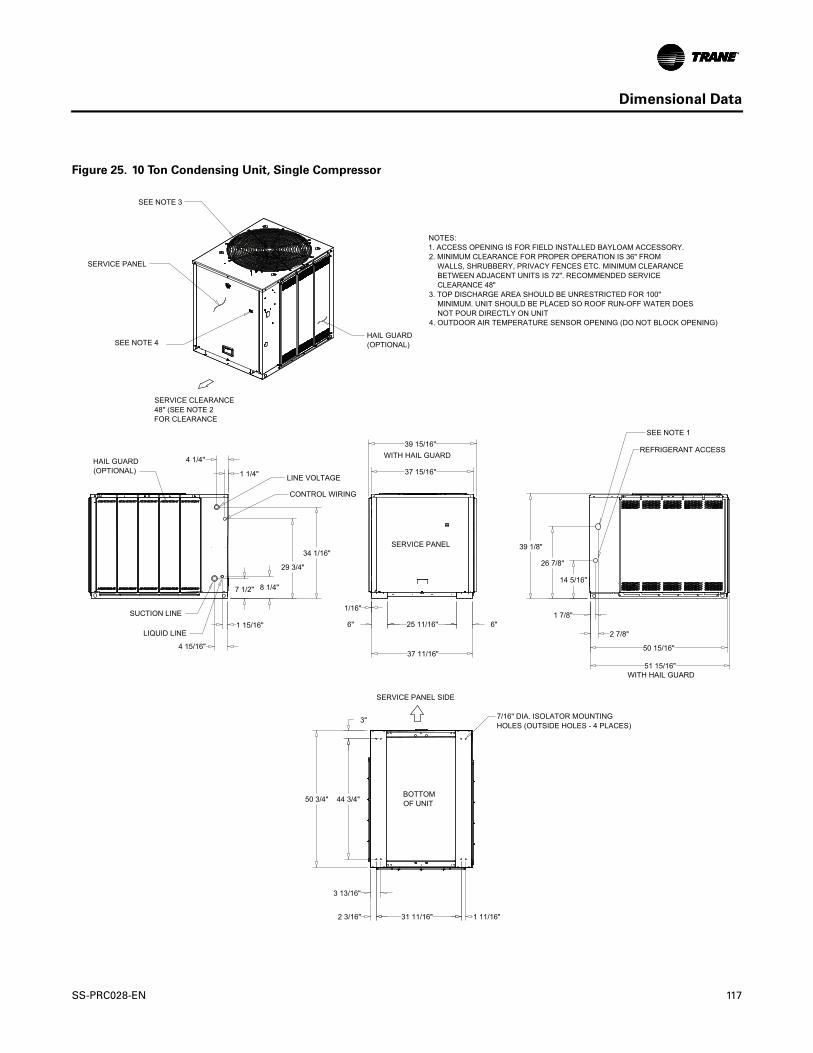
Dimensional Data
Figure 25. 10 Ton Condensing Unit, Single Compressor
BOTTOMOF UNIT
14 5/16"
26 7/8"
39 1/8"
2 7/8"
1 7/8"
34 1/16"
7 1/2" 8 1/4"
29 3/4"
4 15/16"
1 15/16"
4 1/4"
1 1/4"
37 11/16"
1/16"
6" 6"25 11/16"
37 15/16"
3"
50 3/4" 44 3/4"
1 11/16"31 11/16"
3 13/16"
2 3/16"
39 15/16"
50 15/16"
51 15/16"
LIQUID LINE
SUCTION LINE
SERVICE PANEL SIDE
SERVICE CLEARANCE 48" (SEE NOTE 2FOR CLEARANCE
HAIL GUARD (OPTIONAL)
SERVICE PANEL
SEE NOTE 3
HAIL GUARD (OPTIONAL)
SERVICE PANEL
CONTROL WIRING
LINE VOLTAGE
REFRIGERANT ACCESS
SEE NOTE 1
SEE NOTE 4
WITH HAIL GUARD
7/16" DIA. ISOLATOR MOUNTING HOLES (OUTSIDE HOLES - 4 PLACES)
NOTES:1. ACCESS OPENING IS FOR FIELD INSTALLED BAYLOAM ACCESSORY.2. MINIMUM CLEARANCE FOR PROPER OPERATION IS 36" FROM WALLS, SHRUBBERY, PRIVACY FENCES ETC. MINIMUM CLEARANCE BETWEEN ADJACENT UNITS IS 72". RECOMMENDED SERVICE CLEARANCE 48"3. TOP DISCHARGE AREA SHOULD BE UNRESTRICTED FOR 100" MINIMUM. UNIT SHOULD BE PLACED SO ROOF RUN-OFF WATER DOES NOT POUR DIRECTLY ON UNIT4. OUTDOOR AIR TEMPERATURE SENSOR OPENING (DO NOT BLOCK OPENING)
WITH HAIL GUARD
SS-PRC028-EN 117

Dimensional Data
Figure 26. 10 Ton Condensing Unit, Dual Compressor
BOTTOMOF UNIT
14 5/16"
26 7/8"
39 1/8"
2 7/8"
1 7/8"
37 11/16"
1/16"
6" 6"25 11/16"
37 15/16"
3"
50 3/4" 44 3/4"
1 11/16"31 11/16"
3 13/16"
2 3/16"
4 1/4"
1 1/4"
10 3/8"
34 1/16"29 3/4"
2 1/2"
5 1/16"
7 7/8" 9 1/4"6 3/8"
3 15/16"
39 15/16"
50 15/16"
51 15/16"
SUCTION LINE
LIQUID LINE
SERVICE PANEL SIDE
SERVICE CLEARANCE 48" (SEE NOTE 2FOR CLEARANCE)
HAIL GUARD (OPTIONAL)
SERVICE PANEL
SEE NOTE 3
HAIL GUARD (OPTIONAL)
SERVICE PANEL
CONTROL WIRING
LINE VOLTAGEREFRIGERANT ACCESS
SEE NOTE 1
SEE NOTE 4
WITH HAIL GUARD
7/16" DIA. ISOLATOR MOUNTING HOLES (OUTSIDE HOLES - 4 PLACES)
NOTES:1. ACCESS OPENING IS FOR FIELD INSTALLED BAYLOAM ACCESSORY.2. MINIMUM CLEARANCE FOR PROPER OPERATION IS 36" FROM WALLS, SHRUBBERY, PRIVACY FENCES ETC. MINIMUM CLEARANCE BETWEEN ADJACENT UNITS IS 72". RECOMMENDED SERVICE CLEARANCE 48"3. TOP DISCHARGE AREA SHOULD BE UNRESTRICTED FOR 100" MINIMUM. UNIT SHOULD BE PLACED SO ROOF RUN-OFF WATER DOES NOT POUR DIRECTLY ON UNIT4. OUTDOOR AIR TEMPERATURE SENSOR OPENING (DO NOT BLOCK OPENING).
WITH HAIL GUARD
118 SS-PRC028-EN

Dimensional Data
Figure 27. 10 Ton Condensing Unit, Manifolded Compressor
BOTTOMOF UNIT
14 5/16"
26 7/8"
39 1/8"
2 7/8"
1 7/8"
37 11/16"
1/16"
6" 6"25 11/16"
37 15/16"
3"
50 3/4" 44 3/4"
1 11/16"31 11/16"
3 13/16"
2 3/16"
4 1/4"
1 1/4"
8 5/16"
34 1/16"29 3/4"
4 15/16"
1 15/16"
39 15/16"
50 15/16"
51 15/16"
7/16" DIA. ISOLATOR MOUNTING HOLES (OUTSIDE HOLES - 4 PLACES)
NOTES:1. ACCESS OPENING IS FOR FIELD INSTALLED BAYLOAM ACCESSORY.2. MINIMUM CLEARANCE FOR PROPER OPERATION IS 36" FROM WALLS, SHRUBBERY, PRIVACY FENCES ETC. MINIMUM CLEARANCE BETWEEN ADJACENT UNITS IS 72". RECOMMENDED SERVICE CLEARANCE 48"3. TOP DISCHARGE AREA SHOULD BE UNRESTRICTED FOR 100" MINIMUM. UNIT SHOULD BE PLACED SO ROOF RUN-OFF WATER DOES NOT POUR DIRECTLY ON UNIT4. OUTDOOR AIR TEMPERATURE SENSOR OPENING (DO NOT BLOCK OPENING)
LIQUID LINE
SUCTION LINE
SERVICE PANEL SIDE
SERVICE CLEARANCE 48" (SEE NOTE 2FOR CLEARANCE)
HAIL GUARD (OPTIONAL)
SERVICE PANEL
SEE NOTE 3
HAIL GUARD (OPTIONAL)
SERVICE PANEL
CONTROL WIRING
LINE VOLTAGE REFRIGERANT ACCESS
SEE NOTE 1
SEE NOTE 4
WITH HAIL GUARD
WITH HAIL GUARD
SS-PRC028-EN 119

Dimensional Data
Figure 28. 12½ Ton Condensing Unit, Dual Compressor
BOTTOMOF UNIT
51 15/16"
50 15/16"
1/16"
35 3/4"
42 5/16"
11 3/8"
3 3/16"
6 3/8" 7 7/8" 9 5/16"
5 1/16"
1 1/4"
4 1/4"
2 7/8"
32 7/8"44 3/4"
25 11/16"6" 6" 1 13/16"
14 5/16"
37 11/16"
44 3/4"50 3/4"
3"
31 11/16"
3 13/16"
2 3/16" 1 11/16"
37 15/16"
39 15/16"
SUCTION LINE
LIQUID LINE
SERVICE PANEL SIDE
SERVICE CLEARANCE 48" (SEE NOTE 2FOR CLEARANCE
HAIL GUARD (OPTIONAL)
SERVICE PANEL
SEE NOTE 3
HAIL GUARD (OPTIONAL)
SERVICE PANEL
CONTROL WIRING
LINE VOLTAGEREFRIGERANT ACCESS
SEE NOTE 1
SEE NOTE 4
WITH HAIL GUARD
7/16" DIA. ISOLATOR MOUNTING HOLES (OUTSIDE HOLES - 4 PLACES)
NOTES:1. ACCESS OPENING IS FOR FIELD INSTALLED BAYLOAM ACCESSORY.2. MINIMUM CLEARANCE FOR PROPER OPERATION IS 36" FROM WALLS, SHRUBBERY, PRIVACY FENCES ETC. MINIMUM CLEARANCE BETWEEN ADJACENT UNITS IS 72". RECOMMENDED SERVICE CLEARANCE 48"3. TOP DISCHARGE AREA SHOULD BE UNRESTRICTED FOR 100" MINIMUM. UNIT SHOULD BE PLACED SO ROOF RUN-OFF WATER DOES NOT POUR DIRECTLY ON UNIT4. OUTDOOR AIR TEMPERATURE SENSOR OPENING (DO NOT BLOCK OPENING).
WITH HAIL GUARD
120 SS-PRC028-EN

Dimensional Data
Figure 29. 15-20 Ton Condensing Unit, Dual Compressor
BOTTOM OF UNIT
1/16"
9" 9"25 11/16"
3/16"
45 1/8"
41 5/8"39 7/8"
4 3/8"
5 9/16"12 9/16"14 5/8"18 3/4"
6 13/16"
1 3/16"
15/16"
9 1/4"
3 3/8"6 5/8"
3 11/16"
6 5/16"
44"
93"
87"
41 1/2"
2 3/16"3" 6 13/16"
36 7/8"
41 3/8"
41 7/16"
93 5/16"
95 7/16"46"
LINE VOLTAGE
SUCTION LINE
REFRIGERANT ACCESS
LIQUID LINES
SUCTION LINE
NOTES:1. MINIMUM CLEARANCE FOR PROPER OPERATION IS 36" FROM WALLS, SHRUBBERY, PRIVACY FENCES ETC. MINIMUM CLEARANCE BETWEEN ADJACENT UNITS IS 72". RECOMMENDED SERVICE CLEARANCE 48"2. TOP DISCHARGE AREA SHOULD BE UNRESTRICTED FOR 100" MINIMUM. UNIT SHOULD BE PLACED SO ROOF RUN-OFF WATER DOES NOT POUR DIRECTLY ON UNIT3. OUTDOOR AIR TEMPERATURE SENSOR OPENING (DO NOT BLOCK OPENING)
7/16" DIA. ISOLATOR MOUNTING HOLES (OUTSIDE HOLES - 4 PLACES)
SERVICE PANEL SIDE
SERVICE CLEARANCE 48" (SEE NOTE 1FOR CLEARANCE)
HAIL GUARD (OPTIONAL)
HAIL GUARD (OPTIONAL)
SERVICEPANEL
DIMENSIONAL DETAIL
FRONT DETAIL A
SEE NOTE 2
HAIL GUARD (OPTIONAL)
DETAIL ASERVICE PANEL
CONTROLWIRING
WITH HAIL GUARDWITH HAIL GUARD
SEE NOTE 3
SS-PRC028-EN 121

Dimensional Data
Figure 30. 15-20 Ton Condensing Unit, Manifolded Compressor
BOTTOM OF UNIT
1/16"
9" 9"25 11/16"
44"
93"
87"
41 1/2"
2 3/16"3" 6 13/16"
36 7/8"
41 5/8"39 7/8"
9 1/4"
6 5/16"
3 3/8"
15/16"
1 3/16"
6 13/16"
20 1/16"
93 5/16"
41 1/4"
45 1/8"
3/16"
14 5/8"
4 1/8"
46"95 7/16"
CONTROL WIRING
REFRIGERANT ACCESS
LIQUID LINE
SUCTION LINE
NOTES:1. MINIMUM CLEARANCE FOR PROPER OPERATION IS 36" FROM WALLS, SHRUBBERY, PRIVACY FENCES ETC. MINIMUM CLEARANCE BETWEEN ADJACENT UNITS IS 72". RECOMMENDED SERVICE CLEARANCE 48"2. TOP DISCHARGE AREA SHOULD BE UNRESTRICTED FOR 100" MINIMUM. UNIT SHOULD BE PLACED SO ROOF RUN-OFF WATER DOES NOT POUR DIRECTLY ON UNIT3. OUTDOOR AIR TEMPERATURE SENSOR OPENING (DO NOT BLOCK OPENING)
7/16" DIA. ISOLATOR MOUNTING HOLES (OUTSIDE HOLES - 4 PLACES)
SERVICE PANEL SIDE
SERVICE CLEARANCE 48" (SEE NOTE 1FOR CLEARANCE)
HAIL GUARD (OPTIONAL)
HAIL GUARD (OPTIONAL)
SERVICEPANEL
DIMENSIONAL DETAIL
FRONT DETAIL A
SEE NOTE 2
HAIL GUARD (OPTIONAL)
DETAIL ASERVICE PANEL
WITH HAIL GUARDWITH HAIL GUARD
LINE VOLTAGE
SEE NOTE 3
122 SS-PRC028-EN

Dimensional Data
Figure 31. 25 Ton Condensing Unit, Manifolded Compressor
2 3/16"
4 1/4"
BOTTOM OF UNIT
SCALE 1.00 0
41 1/2"36 7/8"
6 13/16"
46"
44 3/16"
25 11/16" 9"9"
.9"
93"
87"
3"
47 3/4"40 5/8"
14 5/8"
8 1/4"
5 13/16"
1 11/16"
1 5/16"
47 1/4"41 7/16"
15 7/16"13 11/16"
38 7/8"
93 5/16"
7 13/16"
6 7/16"
6 13/16"
8 5/16"
SCALE 1.000
41 3/8"
25 TON HEAT PUMP CONDENSERDIMENSIONAL DRAWING
LIQUID LINES
NOTES:1. MINIMUM CLEARANCE FOR PROPER OPERATION IS 36" FROM
WALLS, SHRUBBERY, PRIVACY FENCES ETC. MINIMUM CLEARANCEBETWEEN ADJACENT UNITS IS 72". RECOMMENDED SERVICECLEARANCE 48"
2. TOP DISCHARGE AREA SHOULD BE UNRESTRICTED FOR 100"MINIMUM. UNIT SHOULD BE PLACED SO ROOF RUN-OFF WATER DOESNOT POUR DIRECTLY ON UNIT
3. OUTDOOR AIR TEMPERATURE SENSOR OPENING (DO NOT BLOCK OPENING).
7/16" DIA. ISOLATORMOUNTING HOLES(OUTSIDE HOLES - 4 PLACES)
SERVICE PANEL SIDE
SERVICE CLEARANCE48" (SEE NOTE 1FOR CLEARANCE)
HAIL GUARD(OPTIONAL)
SERVICE PANEL
DIMENSIONAL DETAIL
FRONT DETAIL A
SEE NOTE 2
DETAIL A
SEE NOTE 3
CONTROL WIRINGLINE VOLTAGE
SUCTION LINES
REFRIGERANT ACCESS
CONTROL WIRING
LINE VOLTAGE
HAIL GUARD(OPTIONAL)
WITH OUT HAIL GUARD(UNIT COIL)
SUCTIONLINES
LIQUID LINES
DIMENSIONAL DETAIL
OPIONAL REAR ACCESS
50 3/4"
.38"
SS-PRC028-EN 123

Dimensional Data
Figure 32. 5 Ton Air Handler, Single Circuit
3" (76.2)
48 1/16"(1220.8)
10 7/16"(265.1)
34 9/16"(877.9)
35 5/8"(904.9)
1 1/8"(28.6)
12"(304.8)
13 9/16" (344.5)
20 1/16"(509.6)
1 11/16"(42.9)
5 15/16"(150.8) 13 3/16" (335)
12"(304.8)
13 9/16"(344.5)
13 5/16"(338.14)
1 3/4"(44.45)
2 3/4"(69.9)
DRAIN CONNECTIONFOR HORIZONTAL(SEE NOTE 2,3,5)
32 1/2"(825.5)
12 7/16"(315.9)
1 3/8"(34.9)
.99" (25.15).99" (25.15)
1 3/8" (34.9)
3 3/16" (81)
3 7/16" (87.3)
22 5/8"(574.7)
22 5/8"(574.7)
16 1/4"(412.8)
.77" (19.6)
.50" (12.7)
3 9/16"(90.5)
7 9/16"(192.1)
37 15/16"(963.6)
24 1/16"(611.2)
2 5/16"(58.7)6 7/8"
(174.6)
6 15/16" (176.2)
BOTTOM RETURNSIDE RETURN
CONTROL BOXACCESS PANEL
NOTES:1. PANEL DEPTH 1/2" (12.7) (TYP. ALL PANELS).2. REMOVABLE DRAIN PAN AND ATTACHED DRAIN CONNECTION MAY BE INSTALLED ON END OF UNIT IN EITHER THE VERTICAL OR HORIZONTAL CONFIGURATION, PLASTIC DRAIN PAN ACCESS PLATE ON THE END OF UNIT OPPOSITE DRAIN CONNECTION MUST BE REMOVED TO SLIDE DRAIN PAN OUT OF UNIT FOR CLEANING. ACCESS PLATE MUST BE RE-INSTALLED AFTER SLIDING DRAIN PAN BACK INTO UNIT.3. IF PERIODIC DRAIN PAN CLEANING IS REQUIRED, ALLOW ROOM FOR PARTIAL REMOVAL OF DRAIN PAN CONNECTION AT END OF UNIT.4. 1" (25.4) FEMALE SCHED. 40 (10.2) PVC PIPE DRAIN CONNECTION VERTICAL CONFIGURATION.5. 1" (25.4) FEMALE SCHED. 40 (10.2) PVC PIPE DRAIN CONNECTION HORIZONTAL CONFIGURATION.
SEE NOTES 2,3,4
SEE NOTES 2,3,4
(4) - HOLE FOR HORIZONTALSUSPENSION
COPPER LIQUID LINEFIELD CONNECTION
COPPER SUCTION LINEFIELD CONNECTION
LIQUID LINES
1 3/8" (34.9) O.D. SUCTION LINE
REMOTE BULB TXV
FILTER ACCESS PANEL22" (558.8) MIN. DISTANCEBOTH SIDE
FILTER
SUPPLY OPENING
BOTTOM RETURN
SIDE RETURNBOTTOM RETURN
SUPPLY VERTICAL -RETURN HORIZONTAL /RETURN VERTICAL
SUPPLY HORIZONTAL -RETURN VERTICAL /RETURN HORIZONTAL
(4) - HOLE FOR HORIZONTALSUSPENSION
SIDE RETURN
CONTROL WIRING
LINE VOLTAGE
DUCT FLANGE1" (25.4) HEIGHT
SUPPLYOPEN
HEATERVENTILATION
HEATER CONTROLAND SINGLE POWERENTRY WIRES
32 1/2"(825.5)
2 3/4"(69.9)
124 SS-PRC028-EN

Dimensional Data
Figure 33. 5 Ton Air Handler, Dual Circuit
3" (76.2)
48 1/16"(1220.8)
10 7/16"(265.1)
34 9/16" (877.9)
35 5/8"(904.9)
1 1/8"(28.6)
12"(304.8)
13 9/16"(344.5)
20 1/16"(509.6)
1 11/16"(42.9)
5 15/16"(150.8) 13 3/16" (335)
16 1/8"(409.6)
17 5/16"(439.7)
17 7/8"(454)
12"(304.8)
13 9/16"(344.5)
16 1/8"(409.6)
17 5/16"(439.7)
13 5/16"(338.14)
1 3/4"(44.45)
2 3/4"(69.8)
32 1/2"(825.5)
DRAIN CONNECTIONFOR HORIZONTAL(SEE NOTE 2,3,5)
12 7/16"(315.9)
3 11/16" (93.7)
1 11/16" (42.9)
1 3/8" (34.9)
.99" (25.15).99" (25.15)
1 3/8" (34.9)
1 11/16" (42.9)
3 3/16" (81)
3 11/16" (93.7)
3 7/16" (87.3)
22 5/8"(574.7)
1 13/16"(46.04)
22 5/8"(574.7)
16 1/4"(412.8)
.77" (19.6)
.50" (12.7)
3 9/16"(90.5)
7 9/16"(192.1)
37 15/16"(963.6)
24 1/16"(611.2)
2 5/16"(58.7)
6 7/8"(174.6)
6 15/16"(176.2)
BOTTOM RETURNSIDE RETURN
DUCT FLANGE1" (25.4) HEIGHT
SUPPLYOPEN
CONTROL WIRING
LINE VOLTAGE
CONTROL BOXACCESS PANEL
NOTES:1. PANEL DEPTH 1/2" (12.7) (TYP. ALL PANELS).2. REMOVABLE DRAIN PAN AND ATTACHED DRAIN CONNECTION MAY BE INSTALLED ON END OF UNIT IN EITHER THE VERTICAL OR HORIZONTAL CONFIGURATION, PLASTIC DRAIN PAN ACCESS PLATE ON THE END OF UNIT OPPOSITE DRAIN CONNECTION MUST BE REMOVED TO SLIDE DRAIN PAN OUT OF UNIT FOR CLEANING. ACCESS PLATE MUST BE RE-INSTALLED AFTER SLIDING DRAIN PAN BACK INTO UNIT.3. IF PERIODIC DRAIN PAN CLEANING IS REQUIRED, ALLOW ROOM FOR PARTIAL REMOVAL OF DRAIN CONNECTION AT END OF UNIT.4. 1" (25.4) FEMALE SCHED. 40 (10.2) PVC PIPE DRAIN CONNECTION VERTICAL CONFIGURATION.5. 1" (25.4) FEMALE SCHED. 40 (10.2) PVC PIPE DRAIN CONNECTION HORIZONTAL CONFIGURATION.
SEE NOTES 2,3,4
SEE NOTES 2,3,4
SUPPLY VERTICAL -RETURN HORIZONTAL /RETURN VERTICAL
SUPPLY HORIZONTAL -RETURN VERTICAL /RETURN HORIZONTAL
(4) - HOLE FOR HORIZONTALSUSPENSION
COPPER LIQUID LINEFIELD CONNECTION
COPPER SUCTION LINEFIELD CONNECTION
LIQUID LINES
(2) REMOTE BULB TXV
FILTER ACCESS PANEL22" (558.8) MIN. DISTANCEBOTH SIDE
SIDE RETURN
SIDE RETURNBOTTOM RETURN
BOTTOM RETURN
SUPPLY OPENING
FILTER
(4) HOLE FORHORIZONTALSUSPENSION
DRAIN CONNECTION
SUCTION LINE
COPPER LIQUID LINEFIELD CONNECTION
HEATERVENTILATION
HEATER CONTROLAND SINGLE POWERENTRY WIRES
32 1/2"(825.5)
2 3/4"(69.8)
SS-PRC028-EN 125
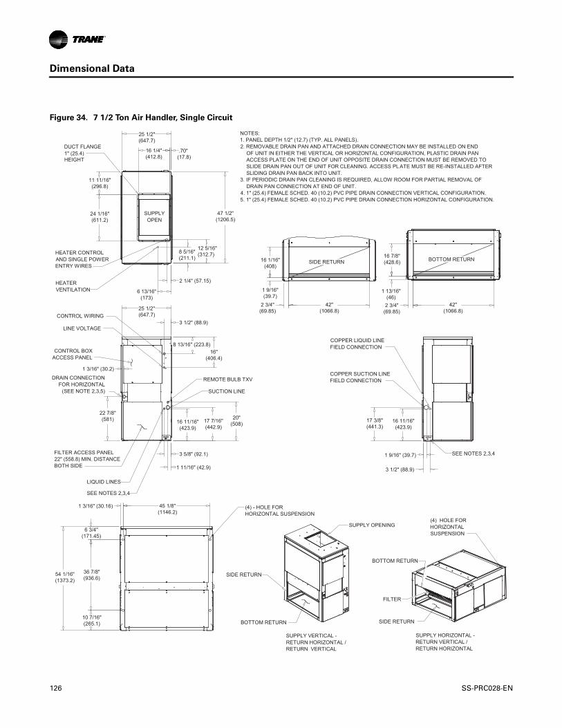
Dimensional Data
Figure 34. 7 1/2 Ton Air Handler, Single Circuit
16 7/8"(428.6)
1 13/16"(46)2 3/4"
(69.85)42"
(1066.8)
1 9/16"(39.7)
16 1/16"(408)
16"(406.4)
8 13/16" (223.8)
3 1/2" (88.9)
1 3/16" (30.2)
22 7/8"(581)
45 1/8"(1146.2)
6 3/4"(171.45)
36 7/8"(936.6)
10 7/16"(265.1)
54 1/16"(1373.2)
1 3/16" (30.16)
16 11/16"(423.9)
17 7/16"(442.9)
20"(508)
3 5/8" (92.1)
1 11/16" (42.9)
16 11/16"(423.9)
17 3/8"(441.3)
1 9/16" (39.7)
3 1/2" (88.9)
25 1/2"(647.7)
16 1/4"(412.8)
.70" (17.8)
25 1/2"(647.7)
24 1/16"(611.2)
11 11/16"(296.8)
47 1/2"(1206.5)
8 5/16"(211.1)
12 5/16"(312.7)
2 1/4" (57.15)
6 13/16"(173)
BOTTOM RETURNSIDE RETURN
CONTROL BOXACCESS PANEL
NOTES:1. PANEL DEPTH 1/2" (12.7) (TYP. ALL PANELS).2. REMOVABLE DRAIN PAN AND ATTACHED DRAIN CONNECTION MAY BE INSTALLED ON END OF UNIT IN EITHER THE VERTICAL OR HORIZONTAL CONFIGURATION, PLASTIC DRAIN PAN ACCESS PLATE ON THE END OF UNIT OPPOSITE DRAIN CONNECTION MUST BE REMOVED TO SLIDE DRAIN PAN OUT OF UNIT FOR CLEANING. ACCESS PLATE MUST BE RE-INSTALLED AFTER SLIDING DRAIN PAN BACK INTO UNIT.3. IF PERIODIC DRAIN PAN CLEANING IS REQUIRED, ALLOW ROOM FOR PARTIAL REMOVAL OF DRAIN PAN CONNECTION AT END OF UNIT.4. 1" (25.4) FEMALE SCHED. 40 (10.2) PVC PIPE DRAIN CONNECTION VERTICAL CONFIGURATION.5. 1" (25.4) FEMALE SCHED. 40 (10.2) PVC PIPE DRAIN CONNECTION HORIZONTAL CONFIGURATION.
SEE NOTES 2,3,4
SEE NOTES 2,3,4
(4) - HOLE FORHORIZONTAL SUSPENSION
COPPER LIQUID LINEFIELD CONNECTION
COPPER SUCTION LINEFIELD CONNECTION
LIQUID LINES
SUCTION LINE
REMOTE BULB TXV
FILTER ACCESS PANEL22" (558.8) MIN. DISTANCEBOTH SIDE
DRAIN CONNECTIONFOR HORIZONTAL
(SEE NOTE 2,3,5)
FILTER
BOTTOM RETURN
SUPPLY VERTICAL -RETURN HORIZONTAL /RETURN VERTICAL
SUPPLY HORIZONTAL -RETURN VERTICAL /RETURN HORIZONTAL
(4) HOLE FORHORIZONTALSUSPENSION
SIDE RETURN
BOTTOM RETURN SIDE RETURN
SUPPLY OPENING
CONTROL WIRING
LINE VOLTAGE
DUCT FLANGE1" (25.4) HEIGHT
SUPPLYOPEN
HEATERVENTILATION
HEATER CONTROLAND SINGLE POWERENTRY WIRES
42"(1066.8)
2 3/4"(69.85)
126 SS-PRC028-EN

Dimensional Data
Figure 35. 7 1/2 Ton Air Handler, Dual Circuit
16 7/8"(406.4)
1 13/16"(46)2 3/4"(69.9)
42"(1066.8)
1 9/16"(39.7)
16 1/16"(408)
20 1/16"(509.6) 16 3/4"
(425.5)16 1/4"(412.8)
13 3/4"(349.3)
3 5/8" (92.1)
1 5/8" (41.3)
1 5/16" (33.3)
11 1/16"(281)
13 3/4"(349.2)
16 1/4"(412.8)
16 3/4"(425.5)
19 1/16"(484.2)
20 1/16"(509.6)
3 5/8" (92.1)
1 5/8" (41.3)
1 5/16" (33.3)
16"(406.4)
8 13/16" (223.8)
3 1/2" (88.9)
1 3/16" (30.2)
22 7/8"(581)
45 1/8"(1146.2)
6 3/4"(171.5)
36 7/8"(936.6)
10 7/16"(265.1)
54 1/16"(1373.2)
1 3/16" (30.2)
25 1/2"(647.7)
16 1/4"(412.8)
.70"(17.78)
25 1/2"(647.7)
24 1/16"(611.2)
11 11/16"(296.9)
47 1/2"(1206.5)
8 5/16"(211.1)
12 5/16"(312.7)
2 1/4" (57.15)
6 13/16" (173)
BOTTOM RETURNSIDE RETURN
CONTROL WIRING
LINE VOLTAGE
CONTROL BOXACCESS PANEL
NOTES:1. PANEL DEPTH 1/2" (12.7) (TYP. ALL PANELS).2. REMOVABLE DRAIN PAN AND ATTACHED DRAIN CONNECTION MAY BE INSTALLED ON END OF UNIT IN EITHER THE VERTICAL OR HORIZONTAL CONFIGURATION, PLASTIC DRAIN PAN ACCESS PLATE ON THE END OF UNIT OPPOSITE DRAIN CONNECTION MUST BE REMOVED TO SLIDE DRAIN PAN OUT OF UNIT FOR CLEANING. ACCESS PLATE MUST BE RE-INSTALLED AFTER SLIDING DRAIN PAN BACK INTO UNIT.3. IF PERIODIC DRAIN PAN CLEANING IS REQUIRED, ALLOW ROOM FOR PARTIAL REMOVAL OF DRAIN PAN CONNECTION AT END OF UNIT.4. 1" (25.4) FEMALE SCHED. 40 (10.2) PVC PIPE DRAIN CONNECTION VERTICAL CONFIGURATION.5. 1" (25.4) FEMALE SCHED. 40 (10.2) PVC PIPE DRAIN CONNECTION HORIZONTAL CONFIGURATION.
SEE NOTES 2,3,4
SEE NOTES 2,3,4(4) - HOLE FOR HORIZONTALSUSPENSION
COPPER LIQUID LINEFIELD CONNECTION
COPPER SUCTION LINEFIELD CONNECTION
LIQUID LINES
SUCTION LINE
(2) REMOTE BULB TXV
FILTER ACCESS PANEL22" (559) MIN. DISTANCEBOTH SIDE
DRAIN CONNECTIONFOR HORIZONTAL
(SEE NOTE 2,3,5)
FILTER
SUPPLY OPENING
BOTTOM RETURN
SIDE RETURN
BOTTOM RETURN
SUPPLY VERTICAL -RETURN HORIZONTAL /RETURN VERTICAL
SUPPLY HORIZONTAL -RETURN VERTICAL /RETURN HORIZONTAL
(4) HOLE FORHORIZONTALSUSPENSION
SIDE RETURN
DUCT FLANGE1" (25.4) HEIGHT
SUPPLYOPEN
HEATERVENTILATION
HEATER CONTROLAND SINGLE POWERENTRY WIRES
42"(1066.8)
2 3/4"(69.9)
SS-PRC028-EN 127

Dimensional Data
Figure 36. 10 Ton Air Handler, Single Circuit
3 1/2" (89)
8 7/8"(225.4) 16 1/16"
(408)
1 3/16"(30.2)22 7/8"
(581)
61 1/8"(1552.6)
6 3/4"(171.45)
36 7/8"(936.63)
10 7/16" (265.1)
54 1/16"(1373.2)
58"(1473.2)
2 3/4"(69.8)
1 13/16"(46)
16 7/8"(428.6)
15 15/16"(404.8)
1 11/16"(42.9)
16 11/16"(423.9)
17 3/8"(441.4)
20"(508)
1 11/16" (42.9)
3 5/8" (92.1)
16 11/16"(423.9)
17 3/8"(441.3)
1 11/16" (42.9)
3 5/8" (92.1)
63 1/2"(1613)
1 3/16" (30.2)
16 1/4"(412.8)
.70" (17.8)
25 1/2"(647.7)
19 11/16"(500.1)
24 1/16"(611.2)
63 1/2"(1612.9)
20 5/16"(515.9)16 5/16"
(414.3)
2 1/4" (57.2)
6 13/16" (173)
BOTTOM RETURNSIDE RETURN
CONTROL BOXACCESS PANEL
NOTES:1. PANEL DEPTH 1/2" (12.7) (TYP. ALL PANELS).2. REMOVABLE DRAIN PAN AND ATTACHED DRAIN CONNECTION MAY BE INSTALLED ON END OF UNIT IN EITHER THE VERTICAL OR HORIZONTAL CONFIGURATION, PLASTIC DRAIN PAN ACCESS PLATE ON THE END OF UNIT OPPOSITE DRAIN CONNECTION MUST BE REMOVED TO SLIDE DRAIN PAN OUT OF UNIT FOR CLEANING. ACCESS PLATE MUST BE RE-INSTALLED AFTER SLIDING DRAIN PAN BACK INTO UNIT.3. IF PERIODIC DRAIN PAN CLEANING IS REQUIRED, ALLOW ROOM FOR PARTIAL REMOVAL OF DRAIN PAN CONNECTION AT END OF UNIT.4. 1" (25.4) FEMALE SCHED. 40 (10.2) PVC PIPE DRAIN CONNECTION VERTICAL CONFIGURATION.5. 1" (25.4) FEMALE SCHED. 40 (10.2) PVC PIPE DRAIN CONNECTION HORIZONTAL CONFIGURATION.
SEE NOTES2,3,4
SEE NOTES 2,3,4
COPPER LIQUID LINEFIELD CONNECTION
COPPER SUCTION LINEFIELD CONNECTION
LIQUID LINES
SUCTION LINE
REMOTE BULB TXV
FILTER ACCESS PANEL22" (559) MIN. DISTANCEBOTH SIDE
DRAIN CONNECTIONFOR HORIZONTAL
(SEE NOTE 2,3,5)
BOTTOM RETURN
SUPPLY VERTICAL -RETURN HORIZONTAL /RETURN VERTICAL
SUPPLY OPENING
SIDE RETURN
(4) - HOLE FORHORIZONTALSUSPENSION
CONTROL WIRING
LINE VOLTAGE
DUCT FLANGE1" (25.4)HEIGHT
SUPPLYOPEN
HEATERVENTILATION
HEATER CONTROLAND SINGLE POWERENTRY WIRES
25 1/2"(647.7)
58"(1473.2)
2 3/4"(69.8)
BOTTOM RETURN
SIDE RETURN
(4) HOLE FORHORIZONTALSUSPENSION
FILTER
SUPPLY HORIZONTAL -RETURN VERTICAL /RETURN HORIZONTAL
128 SS-PRC028-EN

Dimensional Data
Figure 37. 10 Ton Air Handler, Dual Circuit
3 1/2" (89)
8 7/8"(225.4) 16 1/16"
(408)
1 3/16"(30.2)22 7/8"
(581)
61 1/8"(1552.6)
6 3/4"(171.45)
36 7/8"(936.6)
10 7/16" (265.1)
54 1/16"(1373.2)
11" (279.4)13 11/16"(347.7)
16 1/4"(412.8)
16 11/16"(423.9)
19"(482.6)
20"(508)
1 5/16" (33.4)
1 5/8" (41.3)
3 5/8" (92.1) 3 5/8" (92.1)
1 5/8" (41.3)
1 5/16" (33.3)
13 3/4"(349.3)
16 1/4"(412.8)
16 3/4"(425.5)
20 1/16"(509.6)
58"(1473.2)
2 3/4"(69.8)
1 13/16"(46)
16 7/8"(428.6)
15 15/16"(404.8)
1 11/16"(42.9)
1 3/16"(30.2)
25 1/2"(647.7)
16 1/4"(412.7)
.70" (17.8)
25 1/2"(647.7)
19 11/16"(500.1)
24 1/16"(611.2)
63 1/2"(1613)
20 5/16"(515.9)16 5/16"
(414.3)
2 1/4" (57.15)
6 13/16" (173)
BOTTOM RETURNSIDE RETURN
CONTROL BOXACCESS PANEL
NOTES:1. PANEL DEPTH 1/2" (12.7) (TYP. ALL PANELS).2. REMOVABLE DRAIN PAN AND ATTACHED DRAIN CONNECTION MAY BE INSTALLED ON END OF UNIT IN EITHER THE VERTICAL OR HORIZONTAL CONFIGURATION, PLASTIC DRAIN PAN ACCESS PLATE ON THE END OF UNIT OPPOSITE DRAIN CONNECTION MUST BE REMOVED TO SLIDE DRAIN PAN OUT OF UNIT FOR CLEANING. ACCESS PLATE MUST BE RE-INSTALLED AFTER SLIDING DRAIN PAN BACK INTO UNIT.3. IF PERIODIC DRAIN PAN CLEANING IS REQUIRED, ALLOW ROOM FOR PARTIAL REMOVAL OF DRAIN PAN CONNECTION AT END OF UNIT.4. 1" (25.4) FEMALE SCHED. 40 (10.2) PVC PIPE DRAIN CONNECTION VERTICAL CONFIGURATION.5. 1" (25.4) FEMALE SCHED. 40 (10.2) PVC PIPE DRAIN CONNECTION HORIZONTAL CONFIGURATION.
SEE NOTES2,3,4
SEE NOTES 2,3,4
(4) - HOLE FOR HORIZONTALSUSPENSION
COPPER LIQUID LINEFIELD CONNECTION
COPPER SUCTION LINEFIELD CONNECTIONSUCTION LINE
(2) REMOTE BULB TXV
FILTER ACCESS PANEL22" (558.8) MIN. DISTANCEBOTH SIDE
DRAIN CONNECTIONFOR HORIZONTAL
(SEE NOTE 2,3,5)
LIQUID LINES
FILTER
BOTTOM RETURN
SIDE RETURNBOTTOM RETURN
SUPPLY VERTICAL -RETURN HORIZONTAL /RETURN VERTICAL
SUPPLY HORIZONTAL -RETURN VERTICAL /RETURN HORIZONTAL
SIDE RETURN
SUPPLY OPENING
(4) HOLE FORHORIZONTALSUSPENSION
CONTROL WIRING
LINE VOLTAGE
DUCT FLANGE1" (25.4) HEIGHT
SUPPLYOPEN
HEATERVENTILATION
HEATER CONTROLAND SINGLE POWERENTRY WIRES
58"(1473.2)
2 3/4"(69.8)
SS-PRC028-EN 129
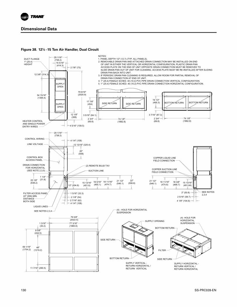
Dimensional Data
Figure 38. 12½ -15 Ton Air Handler, Dual Circuit
19 1/2" (495.3)
74 1/8"(1882.8)
3 7/16" (87.3)
2 3/4"(69.8)
17 7/8"(454)
3 5/16" (84.1)
4 1/4" (108)
20"(508)
12 13/16" (325.4)
22"(558.8)
21 1/2"(546.1)
18 11/16"(474.7)
18 5/16"(465.1)
15 13/16"(401.6)12" (304.8)
21 1/2"(546.1)
1 5/16" (33.3)
2 1/8" (54)2 7/16" (62)4 1/4" (108)
25 1/8"(638.2) 18 11/16"
(474.6)18 3/8"(466.7)
15 13/16"(401.64)
4 1/8" (104.8)
2 5/16" (58.7)
2" (50.8)
9 5/8"(244.5)
48"(1219.2)
11 7/16" (290.5)
1 3/16"(30.2)
69 1/16"(1754.2)
79 5/8"(2022.5)
1 1/4"(31.8)
77 3/16"(1960.6)
29 1/16"(738.2)
2 7/8" (73)
16 5/16"(414.3)
29 1/16"(738.2)
4 5/16" (109.5)
12 1/8"(308)
79 9/16"(2020.9)54 15/16"
(1395.4)
12 3/8" (314.3)
BOTTOM RETURNSIDE RETURN
CONTROL BOXACCESS PANEL
NOTES:1. PANEL DEPTH 1/2" (12.7) (TYP. ALL PANELS).2. REMOVABLE DRAIN PAN AND ATTACHED DRAIN CONNECTION MAY BE INSTALLED ON END OF UNIT IN EITHER THE VERTICAL OR HORIZONTAL CONFIGURATION, PLASTIC DRAIN PAN ACCESS PLATE ON THE END OF UNIT OPPOSITE DRAIN CONNECTION MUST BE REMOVED TO SLIDE DRAIN PAN OUT OF UNIT FOR CLEANING. ACCESS PLATE MUST BE RE-INSTALLED AFTER SLIDING DRAIN PAN BACK INTO UNIT.3. IF PERIODIC DRAIN PAN CLEANING IS REQUIRED, ALLOW ROOM FOR PARTIAL REMOVAL OF DRAIN PAN CONNECTION AT END OF UNIT.4. 1" (25.4) FEMALE SCHED. 40 (10.2) PVC PIPE DRAIN CONNECTION VERTICAL CONFIGURATION.5. 1" (25.4) FEMALE SCHED. 40 (10.2) PVC PIPE DRAIN CONNECTION HORIZONTAL CONFIGURATION.
SEE NOTES2,3,4
SEE NOTES 2,3,4 (4) - HOLE FOR HORIZONTALSUSPENSION
COPPER LIQUID LINEFIELD CONNECTION
COPPER SUCTION LINEFIELD CONNECTION
LIQUID LINES
SUCTION LINE
(2) REMOTE BULB TXV
FILTER ACCESS PANEL22" (559) MIN. DISTANCEBOTH SIDE
DRAIN CONNECTIONFOR HORIZONTAL
(SEE NOTE 2,3,5)
SIDE RETURN BOTTOM RETURN
FILTER
SUPPLY OPENING
BOTTOM RETURN
SIDE RETURN
BOTTOM RETURN
SUPPLY VERTICAL -RETURN HORIZONTAL /RETURN VERTICAL
SUPPLY HORIZONTAL -RETURN VERTICAL /RETURN HORIZONTAL
(4) HOLE FORHORIZONTALSUSPENSION
SIDE RETURN
CONTROL WIRING
LINE VOLTAGE
DUCT FLANGE1" (25.4)HEIGHT
SUPPLYOPEN
HEATER CONTROLAND SINGLE POWERENTRY WIRES
74 1/8"(1882.8)
2 3/4"(69.8)
SUPPLYOPEN
130 SS-PRC028-EN

Dimensional Data
Figure 39. 20-25 Ton Air Handler, Dual Circuit
20 15/16"(531.8)
2 15/16"(74.6)
4 3/4"(120.6)
83 1/8"(2111.4)
3"(76.2)
20 15/16"(531.8)
20" (508)
12 13/16" (325.4)
25 1/2"(647.7)21 13/16"
(554)21 3/8"(542.9)
19 1/8"(485.8)
18 3/8"(466.7)
15 7/8"(403.2)
12 7/8"(327)
25 1/2"(647.7)
11 7/16"(290.5)
50 13/16"(1290.6)
9 5/8"(244.5)
71 7/8"(1825.6)
1 11/16" (42.9) 89 3/16"
(2265.4)
92 9/16"(2351.1)
4" (101.6)
3 3/8" (85.7)
1 15/16" (49.2)
1 11/16" (42.9)
3 7/8" (98.4)
3 1/4" (82.5)
1 7/8" (47.6)
1 9/16" (39.7)
28 1/2"(724)
1 3/16"(30.2)
31 1/8"(790.6)
4 1/4" (108)
16 5/16"(414.3)
31 1/8"(790.6)
4 15/16" (125.4)
92 9/16"(2351.1)
18 5/8"(473.1)
6 7/16" (163.5)
18 7/8"(479.4)
54 15/16"(1395.4)
BOTTOM RETURNSIDE RETURN
CONTROL BOXACCESS PANEL
NOTES:1. PANEL DEPTH 1/2" (12.7) (TYP. ALL PANELS).2. REMOVABLE DRAIN PAN AND ATTACHED DRAIN CONNECTION MAY BE INSTALLED ON END OF UNIT IN EITHER THE VERTICAL OR HORIZONTAL CONFIGURATION, PLASTIC DRAIN PAN ACCESS PLATE ON THE END OF UNIT OPPOSITE DRAIN CONNECTION MUST BE REMOVED TO SLIDE DRAIN PAN OUT OF UNIT CLEANING. ACCESS PLATE MUST BE RE-INSTALLED AFTER SLIDING DRAIN PAN BACK INTO UNIT.3. IF PERIODIC DRAIN PAN CLEANING IS REQUIRED, ALLOW ROOM FOR PARTIAL REMOVAL OF DRAIN PAN CONNECTION AT END OF UNIT.4. 1" (25.4) FEMALE SCHED .40 (10.2) PVC PIPE DRAIN CONNECTION VERTICAL CONFIGURATION.5. 1" (25.4) FEMALE SCHED .40 (10.2) PVC PIPE DRAIN CONNECTION HORIZONTAL CONFIGURATION.
SEE NOTES2,3,4
SEE NOTES 2,3,4(4) - HOLE FOR HORIZONTALSUSPENSION
COPPER LIQUID LINEFIELD CONNECTION
COPPER SUCTION LINEFIELD CONNECTIONSUCTION LINE
REMOTE BULB TXV
FILTER ACCESS PANEL22" (559) MIN. DISTANCEBOTH SIDE
DRAIN CONNECTIONFOR HORIZONTAL
(SEE NOTE 2,3,5)
SIDE RETURN BOTTOM RETURN
LIQUID LINES
(4) HOLE FORHORIZONTALSUSPENSION
SUPPLY HORIZONTAL -RETURN VERTICAL /RETURN HORIZONTAL
SUPPLY VERTICAL -RETURN HORIZONTAL /RETURN VERTICAL
BOTTOM RETURN
SIDE RETURN
FILTER
SUPPLY OPENING
BOTTOM RETURN
SIDE RETURN
CONTROL WIRING
LINE VOLTAGE
DUCT FLANGE1" (25.4) HEIGHT
SUPPLYOPEN
HEATER CONTROLAND SINGLE POWERENTRY WIRES
21 13/16"(554) 19 1/8"
(485.8)18 3/8"(466.7)
15 7/8"(403.2)
83 1/8"(2111.4)
4 3/4"(120.6)
SS-PRC028-EN 131
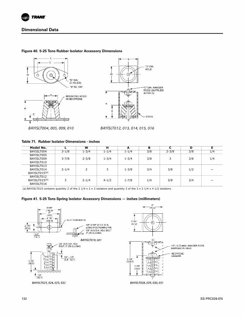
Dimensional Data
Figure 40. 5-25 Tons Rubber Isolator Accessory Dimensions
Table 71. Rubber Isolator Dimensions - inches
Model No. L W H A B C D EBAYISLT004 3-1/8 1-3/4 1-1/4 1-1/4 3/8 2-3/8 3/8 1/4 BAYISLT005
3-7/8 2-3/8 1-3/4 1-3/4 3/8 3 3/8 1/4 BAYISLT009BAYISLT010BAYISLT013
2-1/4 2 3 1-3/8 3/4 3/8 1/2 —BAYISLT014BAYISLT015(a)
BAYISLT0123 2-1/4 4-1/2 1-7/8 1/4 5/8 3/4 —BAYISLT015(a)
BAYISLT016
(a) BAYISLT015 contains quantity 2 of the 2 1/4 x 2 x 3 isolators and quantity 3 of the 3 x 2 1/4 x 4 1/2 isolators.
Figure 41. 5-25 Tons Spring Isolator Accessory Dimensions — inches (millimeters)
132 SS-PRC028-EN

Dimensional Data
Figure 42. Electric Heater Accessory for 5-10 Ton Air Handlers. All dimensions are in inches.
Figure 43. Electric Heater Accessory for 12½-25 Ton Air Handlers. All dimensions are in inches.
SS-PRC028-EN 133

Dimensional Data
Figure 44. Hot Water Coil Accessory. All dimensions are in inches (millimeters).
Table 72. Hot Water Coil Dimensions - inches
Tons Model No. A B C D E F G H J K L M N P Q(a)
5 BAYWATR027 38.14 22.74 13.74 5 9 13.65 16 26 12 6 4.94 7.79 2.88 10.24 2 NPT
7½ BAYWATR028 47.74 25.74 15.95 5 10.84 17.17 16 30 18 8.88 8.45 10.27 2.88 7.77 2.5 NPTI
10 BAYWATR029 63.84 25.74 15.95 6 11.84 17.16 18 36 18 13.88 8.45 10.03 2.88 7.58 2.5 NPTI
12½-15 BAYWATR030 79.74 29.18 14.36 8 10.85 19.67 22 51 18 14.25 6.86 9.91 1.88 7.41 2.5 NPTI
20-25 BAYWATR031 92.74 31.24 16.48 8 10.85 19.67 22 64 18 14.25 8.98 9.88 3.75 7.38 2.5 NPTI
(a) Note internal vs. external pipe threads
134 SS-PRC028-EN

Dimensional Data
Figure 45. Steam Coil Accessory. All dimensions are in inches.
Table 73. Air Handler Dimensions - inches
Tons Model No. A B C D E F G H J K L M N P Q R
5 BAYWATR022 38.14 22.74 14.32 5 9 13.67 16 10.88 11.17 2 1.5 26 12 6 2.87 9.95
7½ BAYWATR023 47.74 25.74 20.14 5 10.84 17.17 16 10.88 11.17 2 2 30 18 8.87 2.87 9.95
10 BAYWATR024 63.84 25.74 20.14 6 11.87 17.16 18 13.70 10.57 2.5 2 36 18 13.87 2.87 9.13
12½-15 BAYWATR025 79.74 29.18 18.55 8 10.85 19.67 22 12.11 10.05 2.5 2 51 18 14.12 1.87 8.61
20-25 BAYWATR026 92.74 31.24 20.67 8 10.85 19.67 22 14.23 10.01 2.5 2 64 18 14.12 3.75 8.58
SS-PRC028-EN 135

Dimensional Data
Figure 46. Discharge Plenum and Grille Accessory
Table 74. Discharge Plenum and Grille Dimensions — No Heat - inches
Tons Model No. A B C
5 BAYPLNM015 37.94 21.94 28
7½ BAYPLNM016 47.5 24.99 28
10 BAYPLNM017 63.5 24.99 28
Table 75. Hydronic Discharge Plenum and Grille Dimensions - inches
Tons Model No. A B C
5 BAYPLNM020 37.87 21.91 14.75
7½ BAYPLNM021 47.5 24.99 14.75
10 BAYPLNM022 63.5 24.99 14.75
12½-15 BAYPLNM018(a)
(a) For use with hydronic heat or no heat.
79.5 27.63 22
20-25 BAYPLNM019(a) 92.5 30.43 24
B A
C
136 SS-PRC028-EN

Dimensional Data
Figure 47. Discharge Plenum and Grille Accessory
Table 76. Discharge Plenum and Grille Dimensions - inches. For use with Electric Heat.
Tons Model No. A B C5 BAYPLNM030 38.07 22.69 29.05
7½ BAYPLNM031 47.86 25.69 29.05 10 BAYPLNM032 63.86 25.69 29.05
12½-15 BAYPLNM033 80.14 29.10 35.11 20-25 BAYPLNM034 92.96 31.10 35.05
Figure 48. Subbase Accessory
Table 77. Subbase Dimensions - inches
Tons Model No. A B5 BAYBASE009 38 22.63
7½ BAYBASE010 47.5 25.5110 BAYBASE011 63.5 25.52
12½-15 BAYBASE012 79.5 29.0420-25 BAYBASE013 92.5 31.14
B
A
C
SS-PRC028-EN 137

Weights
Table 78. TTA Unit and Corner Weights — lbs (60 Hz)
Tons Model No.Shipping Max (lbs) Net Max (lbs)
Corner Weights
1 2 3 4
6 TTA073D 365 300 85 90 44 81
7½ TTA090D 363 298 84 89 44 81
10
TTA120D 467 395 133 103 70 89
TTA120E 510 438 137 127 88 86
TTA120F 509 438 129 140 83 86
12½ TTA150E 543 468 130 151 79 108
15TTA180E 850 723 207 204 151 161
TTA180F 852 725 196 208 153 168
20TTA240E 970 837 262 240 164 171
TTA240F 966 835 257 249 153 176
25 TTA300F 1168 1037 338 266 241 194
Figure 49. TTA073, 090, 120, 150 Figure 50. TTA180, 240, 300
138 SS-PRC028-EN

Weights
Table 79. Standard Air Handler (TWE) — Unit and Corner Weights - lbs (60 Hz)
Tons Model No. Shipping Max (lbs) Net Max (lbs)
Corner Weights - Vertical Corner Weights - Horizontal
1 2 3 4 A B C D
5 TWE061D/E 263 232 55 71 51 55 54 67 50 61
7½ TWE090D/E 360 323 67 99 75 82 56 92 87 88
10 TWE120D/E 429 393 77 121 110 85 79 118 77 119
12½ TWE150E 730 676 168 192 181 135 196 164 145 171
15 TWE180E 729 675 167 192 181 135 196 163 145 171
20 TWE240E 891 818 258 168 161 231 256 181 146 235
25 TWE300E 972 899 211 229 184 275 272 176 228 223
Table 80. SZVAV and 2-Speed VFD (TWE) — Unit and Corner Weights - lbs (60 Hz)
Tons Model No. Shipping Max (lbs) Net Max (lbs)
Corner Weights - Vertical Corner Weights - Horizontal
1 2 3 4 A B C D
10 TWE120D/E 429 393 77 121 110 85 79 118 77 119
12½ TWE150E 730 676 168 192 181 135 196 164 145 171
15 TWE180E 729 675 167 192 181 135 196 163 145 171
20 TWE240E 891 818 258 168 161 231 256 181 146 235
25 TWE300E 972 899 211 229 184 275 272 176 228 223
Figure 51. Vertical - TWE061, 090, 120 Figure 52. Vertical - TWE150, 180, 240, 300
Top View
Control Box Access
Top View
Control Box Access
SS-PRC028-EN 139
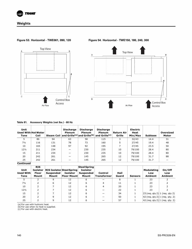
Weights
Figure 53. Horizontal - TWE061, 090, 120 Figure 54. Horizontal - TWE150, 180, 240, 300
Top View
Control BoxAccess
Top View
Control BoxAccess
Table 81. Accessory Weights (net lbs.) - 60 Hz
Unit Used With
TonsHot Water
Coil Steam Coil
Discharge Plenum
and Grille(a)
Discharge Plenum
and Grille(b)
Discharge Plenum
and Grille(c)Return Air
Grille
Electric Heat
Min/Max SubbaseOversized
Motor5 86 94 63 58 115 3 32/43 14.4 31
7½ 116 131 78 73 160 5 27/45 19.4 4810 165 148 97 92 195 7 27/45 23.5 50
12½ 211 234 — 230 235 10 79/100 28.4 8015 211 234 — 230 235 10 79/100 28.4 8020 242 261 — 145 265 12 79/100 31.7 8825 242 261 — 145 265 12 79/100 31.7 —
Continued
Unit Used With
Tons
RIS Isolator
Floor Mount
RIS IsolatorSuspended
Mount
Steel Spring Isolator
Floor Mount
Steel Spring Isolator
Suspended Mount
Control Transformer
Hail Guard Sensors
Modulating Low
Ambient
On/Off Low
Ambient5 2 9 12 6 — 8 1 23 2
7½ 2 6 12 6 4 11 1 23 210 2 7 12 6 4 20 1 23 2
12½ 2 7 12 6 — 22 1 23 215 2 7 12 6 — 34 1 23 (req. qty 2) 1 (req. qty 2)20 2 9 12 6 — 50 1 42 (req. qty 2) 1 (req. qty. 2)25 2 9 12 6 — 57 1 42 (req. qty 2) 1 (req. qty. 2)
(a) For use with hydronic heat.(b) For use when no heat is supplied.(c) For use with electric heat.
140 SS-PRC028-EN

Mechanical Specifications
TTA Condensing Units
General
• Weatherproofed Steel Mounting/Lifting Rails• Hermetic Scroll Compressors• Plate Fin Condenser Coils• Fans and Motors• Standard Operating Range 50-125°F (Min. 0°F with Low Ambient Accy)• Nitrogen Holding Charge• Certified and Rated in Accordance with AHRI and DOE Standards• Certified to UL 1995
Casing
• Zinc Coated, Heavy Gauge, Galvanized Steel• Weather Resistant Baked Enamel Finish• Meets ASTM B117, 672 hour Salt Spray Test• Removable Single Side Maintenance Access Panels• Lifting Handles in Maintenance Access Panels• Unit Base Provisions for Forklift and/or Crane Lifting
Refrigeration System - Single Compressor (TTA073D, TTA090D, TTA120D)
• Single Refrigeration Circuit with Integral Subcooling Circuit• Single Direct Drive Hermetic Scroll Compressor• Suction Gas-Cooled Motor w/ ± 10% Voltage Utilization Range of Unit Nameplate Voltage• Crankcase Heater• Internal Temperature and Current Sensitive Motor Overloads • No Compressor Suction and/or Discharge Valves (Reduced Vibration/Sound)• Factory Installed Liquid Line Filter Drier• Phase Loss/Reverse Rotation Monitor• Liquid Line Service Valve (with gauge port)• Suction Line Service Valve (with gauge port)• External High Pressure Cutout Device• External Low Pressure Cutout Device• Evaporator Defrost Control • Loss of Charge Protection (Discharge Temperature Limit)
Refrigeration System - Dual Compressor (TTA120E, TTA150E, TTA180E,
TTA240E)
• Two (2) Separate and Independent Refrigerant Circuits • Each Refrigeration Circuit Equipped with Integral Subcooling Circuit• Two (2) Direct Drive Hermetic Scroll Compressor• Suction Gas-Cooled Motors w/ ± 10% Voltage Utilization Range of Unit Nameplate Voltage• Crankcase Heaters• Internal Temperature and Current Sensitive Motor Overloads • Factory Installed Liquid Line Filter Driers• Phase Loss/Reverse Rotation Monitor• Liquid Line Service Valves (with gauge port)• Suction Line Service Valves (with gauge port)• No Compressor Suction and/or Discharge Valves (Reduced Vibration/Sound)• External High Pressure Cutout Devices
SS-PRC028-EN 141

Mechanical Specifications
• External Low Pressure Cutout Devices• Evaporator Defrost Control • Loss of Charge Protection (Discharge Temperature Limit)
Refrigeration System - Dual Manifolded Compressors (TTA120F, TTA180F,
TTA240F, TTA300F)
• Single Refrigerant Circuit with Integral Subcooling Circuit.• Two (2) Direct Drive Hermetic Scroll Compressor• Suction Gas-Cooled Motors w/ ± 10% Voltage Utilization Range of Unit Nameplate Voltage• Crankcase Heaters• Internal Temperature and Current Sensitive Motor Overloads • No Compressor Suction and/or Discharge Valves (Reduced Vibration/Sound)• Factory Installed Liquid Line Filter Drier• Phase Loss/Reverse Rotation Monitor• Liquid Line Service Valve (with gauge port)• Suction Line Service Valve (with gauge port)• External High Pressure Cutout Devices• External Low Pressure Cutout Devices• Evaporator Defrost Control • Loss of Charge Protection (Discharge Line Thermostats)• Front or Rear Refrigerant Line Connections (TTA300F only)
Condenser Coil
• 3/8” Internally Enhanced Copper Tube Mechanically Bonded to Lanced Aluminum Plate Fins• Factory Pressure and Leak Tested to 660 psig.• Perforated Steel Hail Guards Available (Factory Installed Option or Field Installed Accessory)
Condenser Fan
• 26" or 28" Propeller Fan(s)• Direct Drive• Statically and Dynamically Balanced
Condenser Motor(s)
• Permanently Lubricated Totally Enclosed or Open Construction• Built-In Current and Thermal Overloads• Ball or Sleeve Bearing Type
Controls
• Choice of Electro-mechanical or Microprocessor• Completely Internally Wired• Numbered and Colored Wires • Contactor Pressure Lugs or Terminal Block• Unit External Mounting Location for Disconnect Device• Single Point Power Entry • Front or rear electrical connections (TTA300F only)
Factory Installed Options
Hail Guards
• Condenser Coil Protection from Hail, Vandals, etc.• Perforated, Painted Galvanized Steel • Factory or Field Installed
142 SS-PRC028-EN

Mechanical Specifications
Black Epoxy Coated Condenser Coil
• Thermoset Vinyl Coating • Bonded to Aluminum Fin Stock (Prior to Fin-Stamping Process)• Economical Protectant in Mildly Corrosive Environments
Lon Talk® Communication Interface
• Factory or Field Installed • Communications Board• Allows Unit Communication as a Tracer™ LCI-R Device• Allows Unit Communication with Generic LonTalk Network Building Automation Controls
Controls: Electro-Mechanical
• 24V Control Circuit• Control Transformer• Thermostat Compatible • Anti-Short Cycle Timer
Controls: Microprocessor
• Centralized Processor • Indoor and Outdoor Temperature Sensors Drive Algorithms Making Decisions for All Heating,
Cooling, and Ventilation• Integrated Anti-Short Cycle Timer• Integrated Time Delay Between Compressors
Field Installed Options
Low Ambient (Fan ON/OFF)
• Provides Unit Cooling Operation to Outdoor Ambient of 0°F • Low Cost Solution • Liquid Line Temperature Controls Condenser Fan Operation• 1 Kit Per Condenser Fan Required
Low Ambient (Modulating)
• Provides Unit Cooling Operation to Outdoor Ambient of 0°F • “Wave-Chopper” • Discharge Line Pressure Controls Condenser Fan Operation• 1 Kit Per Condenser Fan Required
Vibration Isolators
• Neoprene-In-Shear or Spring Flex Choice• Reduce Vibration Transmission to Building Structures, Equipment, and Adjacent Spaces• Reduce Noise Transmission to Building Structures, Equipment, and Adjacent Spaces
Hot Gas Bypass
• Provides Capacity Modulation Solution
Zone Sensor
• Interfaces with Microprocessor Units• Manual or Automatic Programmable• System Malfunction Lights • Remote Sensor Options • Wireless Option
SS-PRC028-EN 143

Mechanical Specifications
Thermostat
• 1H/1C Available • 2H/1C Available• Manual or Automatic Changeover Available• Programmable and Non-Programmable Solutions Available
Lon Talk® Communication Interface
• Factory or Field Installed • Communications Board• Allows Unit Communication as a Tracer™ LCI-R Device• Allows Unit Communication with Generic LonTalk Network Building Automation Controls
BACnet Communication Interface
• Communicates directly with a generic open protocol BACnet MS/TP Network Building Automation System Control
TWE Air Handlers
General
• Completely Factory Assembled• Convertible for Horizontal or Vertical Configuration• Convertible for Cooling Only or Heat Pump Application• Convertible for Left or Right External Connections (Refrigerant and/or Electrical)• Convertible for Front or Bottom Air Return• Nitrogen Holding Charge• Certified to UL 1995 for Indoor Blower Coil Units
Casing
• Zinc Coated, Heavy Gauge, Galvanized Steel• Weather Resistant Baked Enamel Finish• Access Panels with Captive Screws• Completely Insulated with Foil Faced, Cleanable, Fire Retardant, Permanent,
Odorless Glass Fiber Material• Captured or Sealed Insulation Edges• Electrical Connection Bushings or Plugs• Refrigerant Connection Bushings or Plugs• Withstand Elevated Internal Static Pressure
Refrigeration System
• Single or Dual Circuit • Distributor(s)• Thermal Expansion Valves (TXVs)
Evaporator Coil
• 3/8” Internally Enhanced Copper Tube Mechanically Bonded to Lanced Aluminum Plate Fins• Factory Pressure and Leak Tested to 449 psig.• Draw-Through Airflow• Dual Circuits Are Interlaced/Intertwined • Double Sloped, Removable, Cleanable, Composite Drain Pan• Four Drain Pan Positions
144 SS-PRC028-EN

Mechanical Specifications
Indoor Fan
• Double Inlet, Double Width, Forward Curved, Centrifugal Type Fan• Dual Fans On 12.5-25 Ton Air Handlers • Adjustable Belt Drive• Permanently Lubricated Bearings
Indoor Motor
• Adjustable Motor Sheaves (Standard Units)• Fixed Motors Sheaves (SZVAV and 2-Speed VFD)• Thermal Overload Protection• Permanently Lubricated Bearings• Meet Energy Policy of 1992 (EPACT)• Optional Over Sized Motors for High Static Applications
Controls
• Completely Internally Wired• Numbered and Colored Wires• Magnetic Indoor Fan Contactor• Low Voltage Terminal Strip• Single Point Power Entry • Evaporator Defrost Control
Filters
• Access From Side Coil Panels• Filters Slide on Rack• One Inch (1"), Throw-Away Filters on 5-10 Ton Units• Filter Rack Convertible to Two Inch (2") Capability on 5-10 Ton Units• Two Inch (2"), Throw-Away Filters on 12.5-25 Ton Units
Factory Installed Options
• Motor Soft Start - avoids startup belt noise and increases belt life
2-Speed VFD Control
• Variable Frequency Drive (VFD)• Motor Soft Start avoids start up belt noise and increases belt life• Programmable Keypad accessible outside of airstream• VFD rated motor• Factory Installed High Static Motor available
Single Zone Variable Air Volume
• Variable Frequency Drive (VFD)• Motor Soft Start avoids start up belt noise and increases belt life• Programmable Keypad accessible outside of airstream• Airflow adjustment via potentiometer• Discharge air sensor• ReliaTel options module• VFD rated motor• Factory Installed High Static Motor available
SS-PRC028-EN 145

Mechanical Specifications
Field Installed Options
Electric Heaters
• Heavy Duty Nickel Chromium Elements• ETL Approved• Installs Directly On Fan Discharge• One or Two Stage Control (Dependent Upon Capacity)• Single Point Power Entry• Terminal Strip Connections• 460V Heaters
• Internally Wye Connected• Automatic Line Break High Limit Controls
• 230V Heaters• Internally Delta Connected• Automatic Reset of High Limit Controls Through Pilot Duty with Secondary Backup Fuse
Links
Hydronic Heat Coils
• One Row Steam• Two Row Hot Water• Installs Directly On Fan Discharge• Heavy Gauge Sheet Metal Casing Matches Air Handler• Convertible for Horizontal or Vertical Configurations
Discharge Plenums and Grilles
• Vertical, Free Discharge Applications• Heavy Gauge Sheet Metal Casing Matches Air Handler• Satin Finished, 4-Way Adjustable Louver Grilles
Return Air Grilles
• Vertical, Free Discharge Applications• Satin Finished, Non-Adjustable Louver Grilles• Replaces Front Lower Access Panel
Mounting Sub-Base
• Vertical Floor Mount Configuration Requirement • Heavy Gauge Sheet Metal Casing Matches Air Handler• Provides Additional Clearance for Condensate Drain Trapping• Required When Isolators Are Used
Vibration Isolators
• Neoprene-In-Shear or Spring Flex Choice• Floor or Suspended Applications• Reduce Vibration Transmission to Building Structures, Equipment, and Adjacent Spaces• Reduce Noise Transmission to Building Structures, Equipment, and Adjacent Spaces
Over Size Motors
• High Static Applications• Motor, Sheaves, Belt Included
146 SS-PRC028-EN

Trane optimizes the performance of homes and buildings around the world. A business of Ingersoll Rand, the leader in creating and sustaining safe, comfortable and energy efficient environments, Trane offers a broad portfolio of advanced controls and HVAC systems, comprehensive building services, and parts. For more information, visit www.Trane.com. Trane has a policy of continuous product and product data improvement and reserves the right to change design and specifications without notice.
© 2012 Trane All rights reserved
SS-PRC028-EN 01 Mar 2012
Supersedes SS-PRC028-EN (02 Dec 2011)
We are committed to using environmentally
conscious print practices that reduce waste.