o-ring design guide - hi-tech sealshitechseals.com/includes/pdf/o-ring brochure.pdf · 4...
TRANSCRIPT

O-Ring Design Guide

Introduction
Introduction ISO 9001 Registered QMS
Seal Kits
After Hours Service
In 1990, Hi-Tech Seals was founded in Edmonton, Alberta. Since then, our company expanded to six locations across Canada and one location in the United States.
We are an industrial seal, gasket, rubber and plastic component distributor and manufacturer. We focus on providing superior value to our customers. We continually invest in new and inno-vative products, services, and equipment with the intention of helping our customers grow and prosper in an ever-changing world economy.
We offer a personal solution to the business world, tailoring our business relationship to reflect the needs of our clients. We work alongside a variety of industries, while maintaining a high-quality standard in all our products. Our diverse supply chain allows our customers to be confident we will provide a solution that exceeds their needs.
Hi-Tech Seals kit creation program provides customers with an easy to use reordering system for various types of seal kits. Whether its for maintenance or manufactured equipment our sales staff will identify the sealing components and create a kit in our system. The kit can include custom labels with company name and logos, part numbers, and application information. When placing an order, simply provide us with the kit number and receive the parts in one bag.
We are committed to our Quality Management System (QMS). Hi-Tech Seals registered our first branch under an ISO QMS in 1996. Now, all our locations and divisions are registered under the ISO QMS. The four main goals of our policy include:
• Hi-Tech Seals shall distribute and/or manufacture a quality product that will meet our customers' requirements and expectations.
• Hi-Tech Seals shall strive to continually improve the effectiveness of the Quality Management System.
• Hi-Tech Seals' Quality Policy shall be communicated and understood at all levels of the organization.
• Hi-Tech Seals' Quality Policy and Quality Objectives will be reviewed for effectiveness and accuracy during the Annual Management Review.
We have a sales representative available 24 hours a day, 7 days a week. An after-hours sales representative can be reached by contacting your local branch.
2 HITECHSEALS.COM
O-Ring Design Guide

3HITECHSEALS.COM
Compound Specification Guide
Prefix Material Duro.
Temperature
Range Description
N70 Nitrile 70 ± 5-40°C to 120°C -40°F to 248°F
A general service nitrile compound for a wide range of applications including petroleum based fluids. Nitrile compounds also have excellent resistance to compression set, tear and abrasion resistance.
N90 Nitrile 90 ±5-40°C to 120°C-40°F to 248°F
Generally used for higher pressures than the 70 durometer materials, while having comparable media resistance.
LTN Nitrile 70 ±5-54°C to 120°C-65°F to 248°F
A low temperature nitrile compound for use in applications where sealability at lower temperatures is important. Due to the lower acrylonitrile content, this compound will show slightly less resistance to petroleum products.
HS7Hydrogenated
Nitrile70 ± 5
-40°C to 160°C-40°F to 320°F
Hydrogenated nitrile provides an improved resistance to heat, ozone and aging. Similar applications to nitrile but with improved mechanical properties and media resistance. Excellent for many oilfield and automotive applications. H2S resistance up to 10%.
HS8Hydrogenated
Nitrile80 ± 5
-40°C to 160°C-40°F to 320°F
Generally used for higher pressures than the 70 durometer materials while having comparable media resistance.
HS9Hydrogenated
Nitrile90 ± 5
-40°C to 160°C-40°F to 320°F
Generally used for higher pressures than the 80 durometer materials while having comparable media resistance. Improved ED resistance.
V75 Viton™ 75 ± 5-26°C to 204°C-15°F to 400°F
Viton™ compounds have excellent resistance to ozone, weather, oxygen, mineral oil, fuels, hydraulic fluids, aromatics, petroleum fluids, many organic solvents and chemicals. Viton™ is also used in high temperature applications.Viton™ Extreme™ ETP compounds is also available. ETP- Provides the excellent thermal resistance of Viton™ along with significantly advanced chemical resistance.
V90 Viton™ 90 ± 5-26°C to 204°C-15°F to 400°F
Viton™ is generally used for higher pressure than the 75 durometer materials while having comparable media resistance.
LTV Viton™ GLT 75 ±5-40°C to 204°C-40°F to 400°F
Viton™ GLT is used for lower temperature applications than the 75 durometer materials while having comparable media resistance.
PF7 Perfluoroelastomer 75± 5-15°C to 310°C
5°F to 590°FPerfluroelastomer materials have the best heat and chemical resistance performance compared to other elastomer materials.
PF9 Perfluoroelastomer 90 ±5-15°C to 310°C
5°F to 590°FGenerally used for higher pressures than the 75 durometer materials while having comparable media resistance.
A80 Aflas® FEPM 80 ±5-9 °C to 232°C16°F to 450°F
Tetrafluoroethylene-Propylene materials exhibit exceptional thermal and chemical resistance including hot water, steam, acids, alkaline solutions, ammonia, amines, brake fluids, petroleum fluids and sour gas. Low temperature may restrict sealing abilities.
NEO Neoprene 70 ±5-40°C to 121°C-40°F to 250°F
Neoprene is a general purpose material for refrigerants, ozone and weather.
E70 Ethylene- Propylene 70 ± 5-54°C to 150°C-65°F to 302°F
Ethylene-Propylene materials exhibit excellent resistance to water, steam, brake fluids and ozone.
E80 Ethylene- Propylene 80± 5-54°C to 150°C-65°F to 302°F
Generally used for higher pressures than 70 durometer EPDM compounds while having comparable media resistance.
S70 Silicone 70 ± 5-65°C to 232°C-85°F to 446°F
Silicone compounds offer the widest elastomer temperature range but typically cannot be used in dynamic applications or petroleum based fluids.
FS7 Fluorosilicone 70 ±5-56°C to 204°C-69°F to 400°F
Fluorosilicone has improved chemical resistance over silicone including oils, greases, & steam
TEVPTFE Encapsulated
Viton™-60°C to 205°C-76°F to 401°F
TESPTFE Encapsulated
Silicone -60°C to 205°C-76°F to 401°F
F.D.A., NSF and UL listed or approved materials available upon request. We also offer a complete range of coloured or internally lubed compounds as required. Some materials are available in durometers that range from 40 to 95 shore A. Most compounds available in metric sizing. Hi-Tech Seals Inc. also offers a complete range of back-up rings, anti-extrusion devices as well as X-rings and square cut rings. These products are available in a variety of sizes and materials, please contact your sales office for more information.
O-Ring Design Guide
°
4 HITECHSEALS.COM
O-Ring Design GuideMachining Specifications
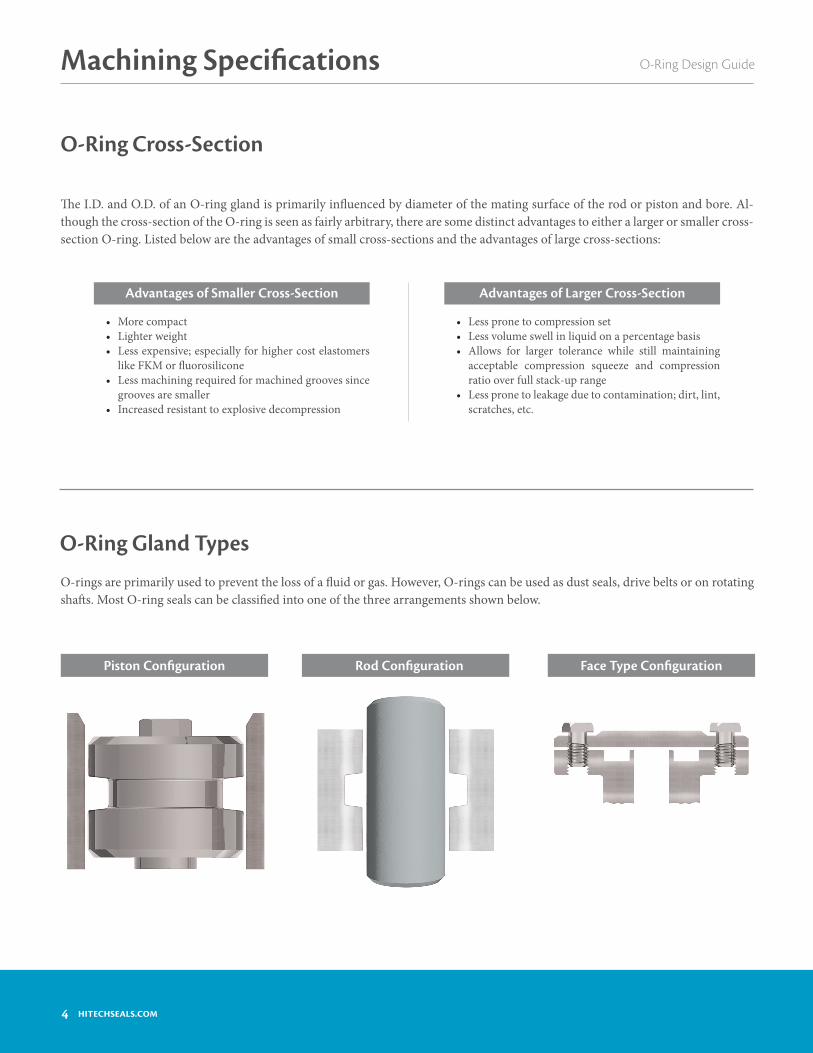
O-Ring Gland Types
O-rings are primarily used to prevent the loss of a fluid or gas. However, O-rings can be used as dust seals, drive belts or on rotating shafts. Most O-ring seals can be classified into one of the three arrangements shown below.
O-Ring Cross-Section
Advantages of Larger Cross-SectionAdvantages of Smaller Cross-Section
• More compact• Lighter weight• Less expensive; especially for higher cost elastomers
like FKM or fluorosilicone• Less machining required for machined grooves since
grooves are smaller• Increased resistant to explosive decompression
• Less prone to compression set• Less volume swell in liquid on a percentage basis• Allows for larger tolerance while still maintaining
acceptable compression squeeze and compression ratio over full stack-up range
• Less prone to leakage due to contamination; dirt, lint, scratches, etc.
Piston Configuration Rod Configuration Face Type Configuration
The I.D. and O.D. of an O-ring gland is primarily influenced by diameter of the mating surface of the rod or piston and bore. Al-though the cross-section of the O-ring is seen as fairly arbitrary, there are some distinct advantages to either a larger or smaller cross-section O-ring. Listed below are the advantages of small cross-sections and the advantages of large cross-sections:

5HITECHSEALS.COM
O-Ring Design Guide Machining Specifications
I.D. Stretch/O.D. Interference
I.D.O.D.
C/S
O-Ring Rod
Gland ØGland Ø
Piston
For hydraulic and pneumatic piston sealing applicationsThe O-ring I.D. should be stretched between 2% and 5% for dynamic applications and 2% and 8% for static applications. For O-rings with an I.D. smaller than 20 mm, this is not always possible which can result in a wider range of stretch. To minimize this range and the maximum stretch, it is necessary to minimize the tolerance of the piston gland diameter, and have a less stringent requirement for the minimum O-ring stretch. In dynamic applications, it is important to keep the maximum stretch to 5% or less to avoid detri-mental effects on sealing performance.
For hydraulic and pneumatic rod sealing applicationsThe O-ring O.D. should be equal to or larger than the rod gland diameter to give interference on the O-ring O.D. The O-ring O.D. should not exceed 3% of the rod gland diameter for O-rings with an I.D. greater than 250 mm, or 5% for O-rings with an I.D. smaller than 250 mm. For O-rings with an I.D. smaller than 20 mm, this is not always possible due to tolerance issues, which can result in a greater O-ring O.D. interference.

6 HITECHSEALS.COM
O-Ring Design Guide
If the I.D. of the O-ring is stretched, the cross-section of the O-ring will decrease. The following table gives the O-ring cross-sections that result from various percentages of I.D. stretch.
Compression
Compression squeeze is the difference between the original O-ring cross-section and the final O-ring cross-section once installed.
For recommended O-ring C/S squeeze (%) values please refer to page 11-12.
Reduction in Cross-Section
O-Ring Selection
Machining Specifications
O-RingSeries
Original O-Ring C/S Reduced O-Ring C/S at % ID Stretch (Inch/mm)
Inch mm 1% 2% 3% 4% 5%000 0.070 1.78 0.069/1.76 0.069/1.74 0.068/1.73 0.068/1.71 0.068/1.69
100 0.103 2.62 0.102/2.59 0.101/2.57 0.100/2.54 0.100/2.52 0.100/2.49
200 0.139 3.53 0.138/3.49 0.137/3.46 0.136/3.42 0.135/3.39 0.134/3.35
300 0.210 5.33 0.208/5.28 0.206/5.22 0.205/5.17 0.204/5.12 0.203/5.06
400 0.275 6.99 0.272/6.92 0.270/6.85 0.268/6.78 0.267/6.71 0.266/6.64
Compression Squeeze
Compression Squeeze = C/S - DDC/S
This can usually be expressed as a percentage: O-ring C/S Squeeze (%) = Compression Squeeze x 100
C/S
7HITECHSEALS.COM
O-Ring Design Guide
O-Ring Selection
Machining Specifications
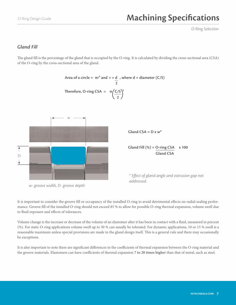
( )
The gland fill is the percentage of the gland that is occupied by the O-ring. It is calculated by dividing the cross-sectional area (CSA) of the O-ring by the cross-sectional area of the gland.
Gland CSA = D x w*
* Effect of gland angle and extrusion gap not addressed.
w
Gland Fill (%) = O-ring CSA x 100
It is important to consider the groove fill or occupancy of the installed O-ring to avoid detrimental effects on radial sealing perfor-mance. Groove fill of the installed O-ring should not exceed 85 % to allow for possible O-ring thermal expansion, volume swell due to fluid exposure and effects of tolerances.
Volume change is the increase or decrease of the volume of an elastomer after it has been in contact with a fluid, measured in percent (%). For static O-ring applications volume swell up to 30 % can usually be tolerated. For dynamic applications, 10 or 15 % swell is a reasonable maximum unless special provisions are made in the gland design itself. This is a general rule and there may occasionally be exceptions.
It is also important to note there are significant differences in the coefficients of thermal expansion between the O-ring material and the groove materials. Elastomers can have coefficients of thermal expansion 7 to 20 times higher than that of metal, such as steel.
w- groove width, D- groove depth
Gland Fill
Therefore, O-ring CSA = π C/S 2
Area of a circle = πr2 and r = d , where d = diameter (C/S)2
2
Gland CSAD

8 HITECHSEALS.COM
Extrusion Gap
Extrusion is a concern for radial seals where there is gap between the piston and the bore for a piston type seal or between the rod and the bore for a rod type seal. It is not typically a concern for face type seals where the metal parts to be sealed are in contact line-to-line. The issue is that at higher pressures and especially for softer O-ring elastomers, the O-ring can be forced by the pressure into the small gap between the piston (or rod) and the bore. Unless the bore and the piston (or rod) are ensured to remain concentric by the hardware, we have to assume that entire possible gap can shift to one side (see diagram below).
Limits for Extrusion
Machining Specifications
There are different methods to counter O-ring extrusion. One of these methods is to increase the durometer rating of the O-ring. However, as the durometer is increased, the O-ring can become less malleable. Another option would be the use of anti-extrusion devices. These are thin rings made of hard plastic materials such as PTFE, nylon, and PEEK. Once in place these rings will provide essentially zero clearance.
Reduce the clearance shown by 60% when using silicone or fluoro-silicone elastomers.
O-Ring Design Guide
AA
Radial Gap (A)
Piston Type SealRadial Extrusion Gap = Bore Ø- Piston Ø
2
Rod Type sealRadial Extrusion Gap = Bore Ø- Rod Ø
2
B
Diametrical Gap (B)Maximum Possible Extrusion Gap
Extrusion
High Pressure
ExtrusionGap
LIMITS FOR EXTRUSION
Total Diametrical Clearance
DUROMETER(HARDNESS SHORE A) –90–70 –80
mmIn.
0 .3 .5 .8 1.0
0 .010 .020 .030 .040
690.0552.0414.0
276.0
207.0
138.0
69.055.2
41.4
27.6
20.7
13.8
6.9
1000080006000
4000
3000
2000
1000800
600
400
300
200
100
EXTRUSION
NOEXTRUSION
Fluid Pressure (psi)Flui
d Pr
essu
re (B
ar)

9HITECHSEALS.COM
Static Axial (Face) Applications
O-RingC/S
DGroove Depth +0.004/-0.000
Squeeze C Groove Width +0.008/-0.000 RGroove Radius% Hydraulic Pneumatic/Vacuum
0.070 0.051 21 - 36 0.126 0.114 0.008 - 0.016
0.103 0.079 19 - 30 0.157 0.142 0.008 - 0.016
0.139 0.106 17 - 26 0.209 0.189 0.016 - 0.031
0.210 0.165 15 - 23 0.299 0.276 0.016 - 0.031
0.275 0.224 13 - 20 0.354 0.335 0.031 - 0.047
Machining Specifications
O-RingC/S
D
Groove Depth
Squeeze E
Diametrical Clearance
Max.
CGroove Width +0.010/-0.000 R
GrooveRadius
NoBack- Up Ring
OneBack- Up Ring
Two Back- Up RingsInches %
0.070 0.049 - 0.057 0.010 - 0.025 14 - 35 0.004 0.110 0.165 0.220 0.008 - 0.016
0.103 0.075 - 0.087 0.013 - 0.031 13 - 30 0.005 0.150 0.205 0.260 0.008 - 0.016
0.139 0.101 - 0.117 0.018 - 0.042 13 - 30 0.006 0.197 0.252 0.307 0.016 - 0.031
0.210 0.156 - 0.180 0.025 - 0.059 12 - 28 0.006 0.283 0.354 0.429 0.016 - 0.031
0.275 0.212 - 0.242 0.028 - 0.069 10 - 25 0.007 0.374 0.484 0.594 0.031 - 0.047
Pneumatic applications typically do not use a back-up ring. Information is based on ISO 3601
Groove Dimensions - ISO 3601Static Radial Applications
O-Ring Design Guide
D
C
E/2
C
D
R
Information is based on ISO 3601
Imperial
R

10 HITECHSEALS.COM
Reciprocating Applications
Imperial
Machining Specifications O-Ring Design Guide
Note: For piston applications groove width (w) values do not apply for 001-003 and 400-424 series O-rings. For rod applications groove width (w)values do not apply for 001-003, 028-050, 135-178, 232-284, 350-395, 400-424 and 430-475.
Information is based on ISO 3601 * Pneumatic applications typically do not use a back-up ring.
DD
E/2 CC
R
R
E/2
O-RingC/S
DSqueeze
E CGroove Width +0.010/-0.000
R
Groove depth Hydraulic Pneumatic Diametrical Clearance
Max.
NoBack- Up
Ring
OneBack- Up
Ring
Two Back- Up
RingsGrooveRadiusHydraulic Pneumatic Inches % Inches %
0.070 0.054 - 0.058 0.056 - 0.0600.009
- 0.01913 - 27
0.007 - 0.017
10 - 24 0.004 0.110 0.165 0.2200.008
- 0.016
0.103 0.081 - 0.088 0.083 - 0.0920.012
- 0.02512 - 24
0.008 - 0.023
8 - 22 0.005 0.150 0.205 0.2600.008
- 0.016
0.139 0.112 - 0.120 0.115 - 0.1250.015
- 0.03111 - 22
0.010 - 0.028
7 - 20 0.006 0.197 0.252 0.3070.016
- 0.031
0.210 0.173 - 0.182 0.177 - 0.1900.023
- 0.04211 - 20
0.015 - 0.038
7 - 18 0.006 0.283 0.354 0.4290.016
- 0.031
0.275 0.229 - 0.244 0.234 - 0.2530.025
- 0.052 9 - 19
0.017 - 0.047
6 - 17 0.007 0.374 0.484 0.5940.031
- 0.047

11HITECHSEALS.COM
Machining Specifications
Groove DetailsPiston & Rod Appliations
O-Ring Design Guide
The surface roughness of the O-ring gland and any mating part has a significant impact on the life and sealing performance of the O-ring. The following are general fluid sealing surface roughness values in microinches (µinch):
For a static mating surface: Ra 16-32 µinchFor a dynamic mating surface: Ra 8-16 µinch
b
ae
c
d
b
c
ad
e
O-Ring Series
O-Ring C/S Wall Angle Break Edge
Radius Chamfer Lenght (e)
c d at 15° d at 20°
Inch mm a b Inch mm Inch mm Inch mm0 0.070 1.78 0.008 - 0.016 0.20 - 0.40 0.043 1.10 0.035 0.90
100 0.103 2.62 0.008 - 0.016 0.20 - 0.40 0.059 1.50 0.043 1.10
200 0.139 3.53 0-5° 0.016 - 0.031 0.40 - 0.80 0.071 1.80 0.055 1.40
300 0.210 5.33 0.016 - 0.031 0.40 - 0.80 0.106 2.70 0.083 2.10
400 0.275 6.99 0.031 - 0.047 0.80 - 1.20 0.142 3.60 0.110 2.80
0.004 - 0.012Inch
0.10 - 0.30mm
Piston Application Rod Application
Surface Finish
Metric

12 HITECHSEALS.COM
Tolerances for Non-Standard O-Rings
Machining Specifications O-Ring Design Guide
Metric
Inside Diameter (I.D) mm Tolerance mm0.68 to 1.53 ± 0.10
1.54 to 11.69 ± 0.13
11.70 to 13.46 ± 0.15
13.47 to 17.53 ± 0.18
17.54 to 20.57 ± 0.20
20.58 to 23.88 ± 0.23
23.89 to 28.70 ± 0.25
28.71 to 35.56 ± 0.30
35.57 to 43.18 ± 0.36
43.19 to 50.80 ± 0.41
50.81 to 58.42 ± 0.46
58.43 to 66.55 ± 0.51
66.56 to 74.93 ± 0.56
74.94 to 83.57 ± 0.61
83.58 to 92.20 ± 0.66
92.21 to 101.60 ± 0.71
101.61 to 117.35 ± 0.76
117.36 to 141.22 ± 0.89
141.23 to 166.37 ± 1.02
166.38 to 192.02 ± 1.14
192.03 to 218.69 ± 1.27
218.70 to 253.37 ± 1.40
253.38 to 289.56 ± 1.52
289.57 to 347.98 ± 1.78
347.99 to 408.94 ± 2.03
408.95 to 472.44 ± 2.29
472.45 to 571.50 ± 2.54
571.51 to 711.20 ± 3.05
711.21 to 855.98 ± 3.56
855.99 to 1005.84 ± 4.06
1005.85 to 1163.32 ± 4.57
1163.33 to 1320.80 ± 5.08
Information based on ISO 3601 Non-Standard Class A O-Rings.
Cross Section (C/S) Tolerance mm0.80 < C/S ≤ 3.15 ± 0.08
3.15 < C/S ≤ 4.50 ± 0.10
4.50 < C/S ≤ 6.30 ± 0.13
6.30 < C/S ≤ 8.40 ± 0.15
*9.00 ≤ C/S ≤ 20.00 ± 0.20
*Based on DIN 3771.
I.D.C/S
Machining information and tolerances for various standards are available through Hi-Tech Seals.
Information provided in this catalogue is meant to aid with seal selec-tion process. Contact us for assistance in designing an application.

13HITECHSEALS.COM
Static Radial Applications
Machining SpecificationsO-Ring Design Guide
Groove Dimensions - Din. 3771
Metric
Information is based on DIN. 3771.
O-ring C/S ±
D
Gland Depth ±
EDiametrical Clearance
CGroove Width
+0.13/-0.00
RGroove Radius
Max. Eccentricity
1.00 0.08 0.72 0.02 0.10 1.35 0.2 0.05
1.20 0.08 0.87 0.02 0.10 1.60 0.2 0.05
1.50 0.08 1.09 0.02 0.10 2.00 0.2 0.05
1.60 0.08 1.16 0.03 0.10 2.10 0.2 0.05
1.78 - 1.80 0.08 1.29 0.03 0.10 2.35 0.2 0.05
1.90 0.08 1.38 0.03 0.10 2.50 0.2 0.05
2.00 0.08 1.45 0.04 0.10 2.65 0.2 0.05
2.40 0.08 1.90 0.04 0.10 3.25 0.2 0.05
2.50 0.08 1.98 0.04 0.10 3.40 0.2 0.05
2.62 0.08 2.07 0.04 0.10 3.55 0.2 0.05
3.00 0.08 2.40 0.04 0.15 4.05 0.5 0.07
3.50 - 3.53 0.10 2.82 0.05 0.15 4.75 0.5 0.07
3.60 0.10 2.88 0.05 0.15 4.85 0.5 0.07
4.00 0.10 3.20 0.06 0.15 5.40 0.5 0.07
4.50 0.10 3.64 0.06 0.15 6.00 0.5 0.07
5.00 0.13 4.04 0.06 0.15 6.70 0.7 0.10
5.33- 5.34 0.13 4.31 0.08 0.15 7.15 0.7 0.10
5.50 0.13 4.45 0.08 0.15 7.35 0.7 0.10
5.70 0.13 4.61 0.08 0.15 7.65 0.7 0.10
6.00 0.13 4.91 0.08 0.18 8.15 0.7 0.13
6.99 0.15 5.72 0.10 0.18 9.50 0.7 0.13
7.00 0.15 5.73 0.10 0.18 9.55 0.7 0.13
7.50 0.15 6.14 0.10 0.18 10.20 1.0 0.13
8.00 0.18 6.55 0.10 0.18 10.90 1.0 0.13
8.40 0.18 6.87 0.15 0.18 11.45 1.0 0.13
9.00 0.2 7.65 0.15 0.18 11.85 1.0 0.13
10.0 0.2 8.50 0.15 0.18 13.20 1.0 0.13
11.0 0.2 9.35 0.15 0.18 14.50 1.0 0.13
12.0 0.2 10.20 0.15 0.18 15.85 1.5 0.13
13.0 0.2 11.05 0.15 0.18 17.15 1.5 0.13
14.0 0.2 11.90 0.3 0.18 18.45 1.5 0.13
16.0 0.2 13.60 0.3 0.18 21.10 1.5 0.13
18.0 0.2 15.30 0.3 0.18 23.75 1.5 0.13
20.0 0.2 17.00 0.3 0.18 26.40 1.5 0.13
C
D
RE/2

14 HITECHSEALS.COM
O-Ring Design Guide
Static Axial (Face) Applications
Groove Dimensions - Din. 3771
Machining SpecificationsMetric
D CGroove Width
O-RingC/S ± Gland Depth ±
Hydraulic+0.13/-0.00
Pneumatic ± 0.13
1.00 0.08 0.75 0.02 1.45 1.20
1.20 0.08 0.90 0.02 1.75 1.45
1.50 0.08 1.13 0.02 2.20 1.80
1.60 0.08 1.20 0.03 2.35 1.90
1.78 - 1.80 0.08 1.34 0.03 2.60 2.15
1.90 0.08 1.43 0.03 2.75 2.30
2.00 0.08 1.51 0.04 2.90 2.40
2.40 0.08 1.82 0.04 3.20 2.80
2.50 0.08 1.90 0.04 3.30 2.90
2.62 0.08 1.99 0.04 3.50 3.05
3.00 0.08 2.27 0.04 3.90 3.45
3.50 - 3.53 0.10 2.67 0.05 4.60 4.05
3.60 0.10 2.72 0.05 4.70 4.10
4.00 0.10 3.03 0.06 5.25 4.60
4.50 0.10 3.60 0.06 6.10 5.10
5.00 0.13 4.00 0.06 6.80 5.70
5.33 0.13 4.26 0.08 7.25 6.05
5.50 0.13 4.40 0.08 7.45 6.25
5.70 0.13 4.56 0.08 7.75 6.50
6.00 0.13 4.98 0.08 8.00 6.75
6.99 0.15 5.80 0.10 9.05 7.85
7.00 0.15 5.81 0.10 9.05 7.90
7.50 0.15 6.23 0.10 9.70 8.40
8.00 0.15 6.64 0.10 10.35 9.00
8.40 0.15 6.97 0.15 10.90 9.45
Information is based on DIN. 3771.
C
D

15HITECHSEALS.COM
O-Ring Design Guide
Reciprocating Applications
Groove Dimensions - Din. 3771
Machining Specifications
D E C
O-RingC/S ± Gland Depth ±
Diametrical Clearance
Groove Width+0.13/-0.00
Max. Eccentricity
1.00 0.08 0.80 0.02 0.10 1.35 0.05
1.20 0.08 0.96 0.02 0.10 1.60 0.05
1.50 0.08 1.20 0.02 0.10 2.00 0.05
1.60 0.08 1.28 0.03 0.10 2.10 0.05
1.78 - 1.80 0.08 1.42 0.03 0.10 2.40 0.05
1.90 0.08 1.52 0.03 0.10 2.50 0.05
2.00 0.08 1.60 0.04 0.10 2.65 0.05
2.40 0.08 2.06 0.04 0.10 3.25 0.05
2.50 0.08 2.15 0.04 0.10 3.40 0.05
2.62 0.08 2.25 0.04 0.10 3.55 0.05
3.00 0.08 2.61 0.04 0.15 4.05 0.07
3.50 - 3.53 0.10 3.07 0.05 0.15 4.75 0.07
3.60 0.10 3.13 0.05 0.15 4.85 0.07
4.00 0.10 3.48 0.05 0.15 5.40 0.07
4.50 0.10 3.99 0.05 0.15 6.00 0.07
5.00 0.13 4.44 0.05 0.15 6.70 0.10
5.33- 5.34 0.13 4.73 0.05 0.15 7.15 0.10
5.50 0.13 4.88 0.05 0.15 7.40 0.10
5.70 0.13 5.06 0.05 0.15 7.60 0.10
6.00 0.13 5.19 0.05 0.18 8.15 0.13
6.99 0.15 6.05 0.05 0.18 9.50 0.13
7.00 0.15 6.06 0.05 0.18 9.55 0.13
7.50 0.15 6.49 0.05 0.18 10.20 0.13
8.00 0.18 6.92 0.05 0.18 10.90 0.13
8.40 0.18 7.27 0.05 0.18 11.45 0.13
9.00 0.20 7.92 0.05 0.18 12.10 0.13
10.00 0.20 8.80 0.05 0.18 13.40 0.13
Information is based on DIN. 3771.
DD
E/2CC
E/2
16 HITECHSEALS.COM
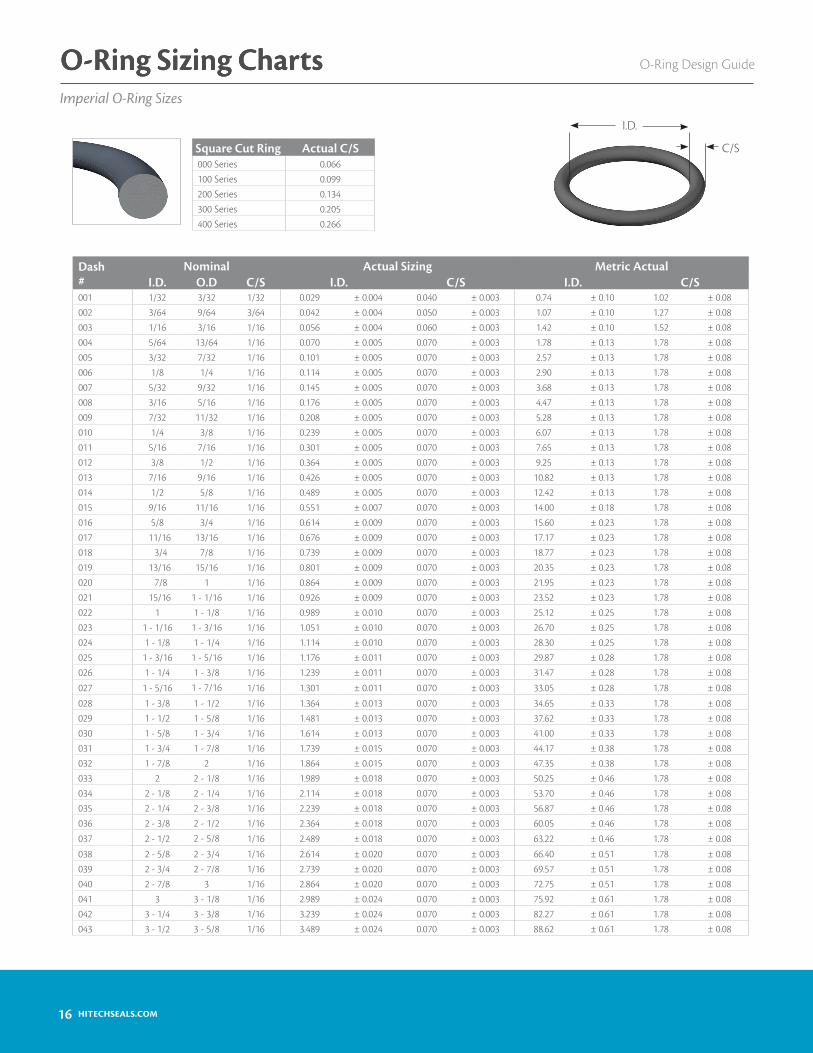
O-Ring Design GuideO-Ring Sizing ChartsImperial O-Ring Sizes
O-Ring Sizing Charts
Dash #
Nominal Actual Sizing Metric ActualI.D. O.D C/S I.D. C/S I.D. C/S
001 1/32 3/32 1/32 0.029 ± 0.004 0.040 ± 0.003 0.74 ± 0.10 1.02 ± 0.08002 3/64 9/64 3/64 0.042 ± 0.004 0.050 ± 0.003 1.07 ± 0.10 1.27 ± 0.08003 1/16 3/16 1/16 0.056 ± 0.004 0.060 ± 0.003 1.42 ± 0.10 1.52 ± 0.08004 5/64 13/64 1/16 0.070 ± 0.005 0.070 ± 0.003 1.78 ± 0.13 1.78 ± 0.08005 3/32 7/32 1/16 0.101 ± 0.005 0.070 ± 0.003 2.57 ± 0.13 1.78 ± 0.08006 1/8 1/4 1/16 0.114 ± 0.005 0.070 ± 0.003 2.90 ± 0.13 1.78 ± 0.08007 5/32 9/32 1/16 0.145 ± 0.005 0.070 ± 0.003 3.68 ± 0.13 1.78 ± 0.08008 3/16 5/16 1/16 0.176 ± 0.005 0.070 ± 0.003 4.47 ± 0.13 1.78 ± 0.08009 7/32 11/32 1/16 0.208 ± 0.005 0.070 ± 0.003 5.28 ± 0.13 1.78 ± 0.08010 1/4 3/8 1/16 0.239 ± 0.005 0.070 ± 0.003 6.07 ± 0.13 1.78 ± 0.08011 5/16 7/16 1/16 0.301 ± 0.005 0.070 ± 0.003 7.65 ± 0.13 1.78 ± 0.08012 3/8 1/2 1/16 0.364 ± 0.005 0.070 ± 0.003 9.25 ± 0.13 1.78 ± 0.08013 7/16 9/16 1/16 0.426 ± 0.005 0.070 ± 0.003 10.82 ± 0.13 1.78 ± 0.08014 1/2 5/8 1/16 0.489 ± 0.005 0.070 ± 0.003 12.42 ± 0.13 1.78 ± 0.08015 9/16 11/16 1/16 0.551 ± 0.007 0.070 ± 0.003 14.00 ± 0.18 1.78 ± 0.08016 5/8 3/4 1/16 0.614 ± 0.009 0.070 ± 0.003 15.60 ± 0.23 1.78 ± 0.08017 11/16 13/16 1/16 0.676 ± 0.009 0.070 ± 0.003 17.17 ± 0.23 1.78 ± 0.08018 3/4 7/8 1/16 0.739 ± 0.009 0.070 ± 0.003 18.77 ± 0.23 1.78 ± 0.08019 13/16 15/16 1/16 0.801 ± 0.009 0.070 ± 0.003 20.35 ± 0.23 1.78 ± 0.08020 7/8 1 1/16 0.864 ± 0.009 0.070 ± 0.003 21.95 ± 0.23 1.78 ± 0.08021 15/16 1 - 1/16 1/16 0.926 ± 0.009 0.070 ± 0.003 23.52 ± 0.23 1.78 ± 0.08022 1 1 - 1/8 1/16 0.989 ± 0.010 0.070 ± 0.003 25.12 ± 0.25 1.78 ± 0.08023 1 - 1/16 1 - 3/16 1/16 1.051 ± 0.010 0.070 ± 0.003 26.70 ± 0.25 1.78 ± 0.08024 1 - 1/8 1 - 1/4 1/16 1.114 ± 0.010 0.070 ± 0.003 28.30 ± 0.25 1.78 ± 0.08025 1 - 3/16 1 - 5/16 1/16 1.176 ± 0.011 0.070 ± 0.003 29.87 ± 0.28 1.78 ± 0.08026 1 - 1/4 1 - 3/8 1/16 1.239 ± 0.011 0.070 ± 0.003 31.47 ± 0.28 1.78 ± 0.08
027 1 - 5/16 1 - 7/16 1/16 1.301 ± 0.011 0.070 ± 0.003 33.05 ± 0.28 1.78 ± 0.08
028 1 - 3/8 1 - 1/2 1/16 1.364 ± 0.013 0.070 ± 0.003 34.65 ± 0.33 1.78 ± 0.08029 1 - 1/2 1 - 5/8 1/16 1.481 ± 0.013 0.070 ± 0.003 37.62 ± 0.33 1.78 ± 0.08030 1 - 5/8 1 - 3/4 1/16 1.614 ± 0.013 0.070 ± 0.003 41.00 ± 0.33 1.78 ± 0.08031 1 - 3/4 1 - 7/8 1/16 1.739 ± 0.015 0.070 ± 0.003 44.17 ± 0.38 1.78 ± 0.08032 1 - 7/8 2 1/16 1.864 ± 0.015 0.070 ± 0.003 47.35 ± 0.38 1.78 ± 0.08033 2 2 - 1/8 1/16 1.989 ± 0.018 0.070 ± 0.003 50.25 ± 0.46 1.78 ± 0.08034 2 - 1/8 2 - 1/4 1/16 2.114 ± 0.018 0.070 ± 0.003 53.70 ± 0.46 1.78 ± 0.08035 2 - 1/4 2 - 3/8 1/16 2.239 ± 0.018 0.070 ± 0.003 56.87 ± 0.46 1.78 ± 0.08036 2 - 3/8 2 - 1/2 1/16 2.364 ± 0.018 0.070 ± 0.003 60.05 ± 0.46 1.78 ± 0.08
037 2 - 1/2 2 - 5/8 1/16 2.489 ± 0.018 0.070 ± 0.003 63.22 ± 0.46 1.78 ± 0.08
038 2 - 5/8 2 - 3/4 1/16 2.614 ± 0.020 0.070 ± 0.003 66.40 ± 0.51 1.78 ± 0.08039 2 - 3/4 2 - 7/8 1/16 2.739 ± 0.020 0.070 ± 0.003 69.57 ± 0.51 1.78 ± 0.08040 2 - 7/8 3 1/16 2.864 ± 0.020 0.070 ± 0.003 72.75 ± 0.51 1.78 ± 0.08041 3 3 - 1/8 1/16 2.989 ± 0.024 0.070 ± 0.003 75.92 ± 0.61 1.78 ± 0.08042 3 - 1/4 3 - 3/8 1/16 3.239 ± 0.024 0.070 ± 0.003 82.27 ± 0.61 1.78 ± 0.08043 3 - 1/2 3 - 5/8 1/16 3.489 ± 0.024 0.070 ± 0.003 88.62 ± 0.61 1.78 ± 0.08
I.D.
C/SSquare Cut Ring Actual C/S000 Series 0.066100 Series 0.099200 Series 0.134300 Series 0.205400 Series 0.266

17HITECHSEALS.COM
O-Ring Design Guide O-Ring Sizing ChartsImperial O-Ring Sizes
O-Ring Sizing Charts
Dash #
Nominal Imperial Actual Metric ActualI.D. O.D. C/S I.D. C/S I.D. C/S
044 3 - 3/4 3 - 7/8 1/16 3.739 ± 0.027 0.070 ± 0.003 94.97 ± 0.69 1.78 ± 0.08045 4 4 - 1/8 1/16 3.989 ± 0.027 0.070 ± 0.003 101.32 ± 0.69 1.78 ± 0.08046 4 - 1/4 4 - 3/8 1/16 4.239 ± 0.030 0.070 ± 0.003 107.67 ± 0.76 1.78 ± 0.08047 4 - 1/2 4 - 5/8 1/16 4.489 ± 0.030 0.070 ± 0.003 114.02 ± 0.76 1.78 ± 0.08048 4 - 3/4 4 - 7/8 1/16 4.739 ± 0.030 0.070 ± 0.003 120.37 ± 0.76 1.78 ± 0.08049 5 5 - 1/8 1/16 4.989 ± 0.037 0.070 ± 0.003 126.72 ± 0.94 1.78 ± 0.08050 5 - 1/4 5 - 3/8 1/16 5.239 ± 0.037 0.070 ± 0.003 133.07 ± 0.94 1.78 ± 0.08
102 1/16 1/4 3/32 0.049 ± 0.005 0.103 ± 0.003 1.24 ± 0.13 2.62 ± 0.08
103 3/32 9/32 3/32 0.081 ± 0.005 0.103 ± 0.003 2.06 ± 0.13 2.62 ± 0.08104 1/8 5/16 3/32 0.112 ± 0.005 0.103 ± 0.003 2.84 ± 0.13 2.62 ± 0.08105 5/32 11/32 3/32 0.143 ± 0.005 0.103 ± 0.003 3.63 ± 0.13 2.62 ± 0.08106 3/16 3/8 3/32 0.174 ± 0.005 0.103 ± 0.003 4.42 ± 0.13 2.62 ± 0.08107 7/32 13/32 3/32 0.206 ± 0.005 0.103 ± 0.003 5.23 ± 0.13 2.62 ± 0.08108 1/4 7/16 3/32 0.237 ± 0.005 0.103 ± 0.003 6.02 ± 0.13 2.62 ± 0.08109 5/16 1/2 3/32 0.299 ± 0.005 0.103 ± 0.003 7.59 ± 0.13 2.62 ± 0.08110 3/8 9/16 3/32 0.362 ± 0.005 0.103 ± 0.003 9.19 ± 0.13 2.62 ± 0.08111 7/16 5/8 3/32 0.424 ± 0.005 0.103 ± 0.003 10.77 ± 0.13 2.62 ± 0.08112 1/2 11/16 3/32 0.487 ± 0.005 0.103 ± 0.003 12.37 ± 0.13 2.62 ± 0.08113 9/16 3/4 3/32 0.549 ± 0.007 0.103 ± 0.003 13.94 ± 0.18 2.62 ± 0.08114 5/8 13/16 3/32 0.612 ± 0.009 0.103 ± 0.003 15.54 ± 0.23 2.62 ± 0.08115 11/16 7/8 3/32 0.674 ± 0.009 0.103 ± 0.003 17.12 ± 0.23 2.62 ± 0.08116 3/4 15/16 3/32 0.737 ± 0.009 0.103 ± 0.003 18.72 ± 0.23 2.62 ± 0.08117 13/16 1 3/32 0.799 ± 0.010 0.103 ± 0.003 20.29 ± 0.25 2.62 ± 0.08118 7/8 1 - 1/16 3/32 0.862 ± 0.010 0.103 ± 0.003 21.89 ± 0.25 2.62 ± 0.08119 15/16 1 - 1/8 3/32 0.924 ± 0.010 0.103 ± 0.003 23.47 ± 0.25 2.62 ± 0.08
120 1 1 - 3/16 3/32 0.987 ± 0.010 0.103 ± 0.003 25.07 ± 0.25 2.62 ± 0.08
121 1 - 1/16 1 - 1/4 3/32 1.049 ± 0.010 0.103 ± 0.003 26.64 ± 0.25 2.62 ± 0.08122 1 - 1/8 1 - 5/16 3/32 1.112 ± 0.010 0.103 ± 0.003 28.24 ± 0.25 2.62 ± 0.08123 1 - 3/16 1 - 3/8 3/32 1.174 ± 0.012 0.103 ± 0.003 29.82 ± 0.30 2.62 ± 0.08124 1 - 1/4 1 - 7/16 3/32 1.237 ± 0.012 0.103 ± 0.003 31.42 ± 0.30 2.62 ± 0.08125 1 - 5/16 1 - 1/2 3/32 1.299 ± 0.012 0.103 ± 0.003 32.99 ± 0.30 2.62 ± 0.08126 1 - 3/8 1 - 9/16 3/32 1.362 ± 0.012 0.103 ± 0.003 34.59 ± 0.30 2.62 ± 0.08127 1 - 7/16 1 - 5/8 3/32 1.424 ± 0.012 0.103 ± 0.003 36.17 ± 0.30 2.62 ± 0.08128 1 - 1/2 1 - 11/16 3/32 1.487 ± 0.012 0.103 ± 0.003 37.77 ± 0.30 2.62 ± 0.08129 1 - 9/16 1 - 3/4 3/32 1.549 ± 0.015 0.103 ± 0.003 39.34 ± 0.38 2.62 ± 0.08130 1 - 5/8 1 - 13/16 3/32 1.612 ± 0.015 0.103 ± 0.003 40.94 ± 0.38 2.62 ± 0.08131 1 - 11/16 1 - 7/8 3/32 1.674 ± 0.015 0.103 ± 0.003 42.52 ± 0.38 2.62 ± 0.08132 1 - 3/4 1 - 15/16 3/32 1.737 ± 0.015 0.103 ± 0.003 44.12 ± 0.38 2.62 ± 0.08133 1 - 13/16 2 3/32 1.799 ± 0.015 0.103 ± 0.003 45.69 ± 0.38 2.62 ± 0.08134 1 - 7/8 2 - 1/16 3/32 1.862 ± 0.015 0.103 ± 0.003 47.29 ± 0.38 2.62 ± 0.08135 1 - 15/16 2 - 1/8 3/32 1.925 ± 0.017 0.103 ± 0.003 48.90 ± 0.43 2.62 ± 0.08136 2 2 - 3/16 3/32 1.987 ± 0.017 0.103 ± 0.003 50.47 ± 0.43 2.62 ± 0.08

18 HITECHSEALS.COM
O-Ring Design GuideO-Ring Sizing ChartsImperial O-Ring Sizes
O-Ring Sizing Charts
Dash #
Nominal Imperial Actual Metric ActualI.D. O.D. C/S I.D. C/S I.D. C/S
137 2 - 1/16 2 - 1/4 3/32 2.050 ± 0.017 0.103 ± 0.003 52.07 ± 0.43 2.62 ± 0.08138 2 - 1/8 2 - 5/16 3/32 2.112 ± 0.017 0.103 ± 0.003 53.64 ± 0.43 2.62 ± 0.08139 2 - 3/16 2 - 3/8 3/32 2.175 ± 0.017 0.103 ± 0.003 55.25 ± 0.43 2.62 ± 0.08140 2 - 1/4 2 - 7/16 3/32 2.237 ± 0.017 0.103 ± 0.003 56.82 ± 0.43 2.62 ± 0.08141 2 - 5/16 2 - 1/2 3/32 2.300 ± 0.020 0.103 ± 0.003 58.42 ± 0.51 2.62 ± 0.08142 2 - 3/8 2 - 9/16 3/32 2.362 ± 0.020 0.103 ± 0.003 59.99 ± 0.51 2.62 ± 0.08143 2 - 7/16 2 - 5/8 3/32 2.425 ± 0.020 0.103 ± 0.003 61.60 ± 0.51 2.62 ± 0.08144 2 - 1/2 2 - 11/16 3/32 2.487 ± 0.020 0.103 ± 0.003 63.17 ± 0.51 2.62 ± 0.08145 2 - 9/16 2 - 3/4 3/32 2.550 ± 0.020 0.103 ± 0.003 64.77 ± 0.51 2.62 ± 0.08146 2 - 5/8 2 - 13/16 3/32 2.612 ± 0.020 0.103 ± 0.003 66.34 ± 0.51 2.62 ± 0.08147 2 - 11/16 2 - 7/8 3/32 2.675 ± 0.022 0.103 ± 0.003 67.95 ± 0.56 2.62 ± 0.08148 2 - 3/4 2 - 15/16 3/32 2.737 ± 0.022 0.103 ± 0.003 69.52 ± 0.56 2.62 ± 0.08149 2 - 13/16 3 3/32 2.800 ± 0.022 0.103 ± 0.003 71.12 ± 0.56 2.62 ± 0.08150 2 - 7/8 3 - 1/16 3/32 2.862 ± 0.022 0.103 ± 0.003 72.69 ± 0.56 2.62 ± 0.08151 3 3 - 3/16 3/32 2.987 ± 0.024 0.103 ± 0.003 75.87 ± 0.61 2.62 ± 0.08152 3 - 1/4 3 - 7/16 3/32 3.237 ± 0.024 0.103 ± 0.003 82.22 ± 0.61 2.62 ± 0.08153 3 - 1/2 3 - 11/16 3/32 3.487 ± 0.024 0.103 ± 0.003 88.57 ± 0.61 2.62 ± 0.08154 3 - 3/4 2 - 15/16 3/32 3.737 ± 0.028 0.103 ± 0.003 94.92 ± 0.71 2.62 ± 0.08155 4 4 - 3/16 3/32 3.987 ± 0.028 0.103 ± 0.003 101.27 ± 0.71 2.62 ± 0.08156 4 - 1/4 4 - 7/16 3/32 4.237 ± 0.030 0.103 ± 0.003 107.62 ± 0.76 2.62 ± 0.08157 4 - 1/2 4 -11/16 3/32 4.487 ± 0.030 0.103 ± 0.003 113.97 ± 0.76 2.62 ± 0.08158 4 - 3/4 4 - 15/16 3/32 4.737 ± 0.030 0.103 ± 0.003 120.32 ± 0.76 2.62 ± 0.08159 5 5 - 3/16 3/32 4.987 ± 0.035 0.103 ± 0.003 126.67 ± 0.89 2.62 ± 0.08160 5 - 1/4 5 - 7/16 3/32 5.237 ± 0.035 0.103 ± 0.003 133.02 ± 0.89 2.62 ± 0.08161 5 - 1/2 5 - 11/16 3/32 5.487 ± 0.035 0.103 ± 0.003 139.37 ± 0.89 2.62 ± 0.08162 5 - 3/4 5 - 15/16 3/32 5.737 ± 0.035 0.103 ± 0.003 145.72 ± 0.89 2.62 ± 0.08
163 6 6 - 3/16 3/32 5.987 ± 0.035 0.103 ± 0.003 152.07 ± 0.89 2.62 ± 0.08
164 6 - 1/4 6 - 7/16 3/32 6.237 ± 0.040 0.103 ± 0.003 158.42 ± 1.02 2.62 ± 0.08
165 6 - 1/2 6 - 11/16 3/32 6.487 ± 0.040 0.103 ± 0.003 164.77 ± 1.02 2.62 ± 0.08166 6 - 3/4 6 - 15/16 3/32 6.737 ± 0.040 0.103 ± 0.003 171.12 ± 1.02 2.62 ± 0.08167 7 7 - 3/16 3/32 6.987 ± 0.040 0.103 ± 0.003 177.47 ± 1.02 2.62 ± 0.08168 7 - 1/4 7 - 7/16 3/32 7.237 ± 0.045 0.103 ± 0.003 183.82 ± 1.14 2.62 ± 0.08169 7 - 1/2 7 - 11/16 3/32 7.487 ± 0.045 0.103 ± 0.003 190.17 ± 1.14 2.62 ± 0.08170 7 - 3/4 7 - 15/16 3/32 7.737 ± 0.045 0.103 ± 0.003 196.52 ± 1.14 2.62 ± 0.08171 8 8 - 3/16 3/32 7.987 ± 0.045 0.103 ± 0.003 202.87 ± 1.14 2.62 ± 0.08172 8 - 1/4 8 - 7/16 3/32 8.237 ± 0.050 0.103 ± 0.003 209.22 ± 1.27 2.62 ± 0.08173 8 - 1/2 8 - 11/16 3/32 8.487 ± 0.050 0.103 ± 0.003 215.57 ± 1.27 2.62 ± 0.08174 8 - 3/4 8 - 15/16 3/32 8.737 ± 0.050 0.103 ± 0.003 221.92 ± 1.27 2.62 ± 0.08175 9 9 - 3/16 3/32 8.987 ± 0.050 0.103 ± 0.003 228.27 ± 1.27 2.62 ± 0.08176 9 - 1/4 9 - 7/16 3/32 9.237 ± 0.055 0.103 ± 0.003 234.62 ± 1.40 2.62 ± 0.08177 9 - 1/2 9 - 11/16 3/32 9.487 ± 0.055 0.103 ± 0.003 240.97 ± 1.40 2.62 ± 0.08178 9 - 3/4 9 - 15/16 3/32 9.737 ± 0.055 0.103 ± 0.003 247.32 ± 1.40 2.62 ± 0.08
201 3/16 7/16 1/8 0.171 ± 0.005 0.139 ± 0.004 4.34 ± 0.13 3.53 ± 0.10202 1/4 1/2 1/8 0.234 ± 0.005 0.139 ± 0.004 5.94 ± 0.13 3.53 ± 0.10203 5/16 9/16 1/8 0.296 ± 0.005 0.139 ± 0.004 7.52 ± 0.13 3.53 ± 0.10204 3/8 5/8 1/8 0.359 ± 0.005 0.139 ± 0.004 9.12 ± 0.13 3.53 ± 0.10205 7/16 11/16 1/8 0.421 ± 0.005 0.139 ± 0.004 10.69 ± 0.13 3.53 ± 0.10206 1/2 3/4 1/8 0.484 ± 0.005 0.139 ± 0.004 12.29 ± 0.13 3.53 ± 0.10207 9/16 13/16 1/8 0.546 ± 0.007 0.139 ± 0.004 13.87 ± 0.18 3.53 ± 0.10

19HITECHSEALS.COM
O-Ring Design Guide O-Ring Sizing ChartsImperial O-Ring Sizes
Dash #
Nominal Imperial Actual Metric ActualI.D. O.D. C/S I.D. C/S I.D. C/S
208 5/8 7/8 1/8 0.609 ± 0.009 0.139 ± 0.004 15.47 ± 0.23 3.53 ± 0.10209 11/16 15/16 1/8 0.671 ± 0.009 0.139 ± 0.004 17.04 ± 0.23 3.53 ± 0.10210 3/4 1 1/8 0.734 ± 0.010 0.139 ± 0.004 18.64 ± 0.25 3.53 ± 0.10211 13/16 1 - 1/16 1/8 0.796 ± 0.010 0.139 ± 0.004 20.22 ± 0.25 3.53 ± 0.10212 7/8 1 - 1/8 1/8 0.859 ± 0.010 0.139 ± 0.004 21.82 ± 0.25 3.53 ± 0.10213 15/16 1 - 3/16 1/8 0.921 ± 0.010 0.139 ± 0.004 23.39 ± 0.25 3.53 ± 0.10214 1 1 - 1/4 1/8 0.984 ± 0.010 0.139 ± 0.004 24.99 ± 0.25 3.53 ± 0.10215 1 - 1/16 1 - 5/16 1/8 1.046 ± 0.010 0.139 ± 0.004 26.57 ± 0.25 3.53 ± 0.10216 1 - 1/8 1 - 3/8 1/8 1.109 ± 0.012 0.139 ± 0.004 28.17 ± 0.30 3.53 ± 0.10217 1 - 3/16 1 - 7/16 1/8 1.171 ± 0.012 0.139 ± 0.004 29.74 ± 0.30 3.53 ± 0.10218 1 - 1/4 1 - 1/2 1/8 1.234 ± 0.012 0.139 ± 0.004 31.34 ± 0.30 3.53 ± 0.10219 1 - 5/16 1 - 9/16 1/8 1.296 ± 0.012 0.139 ± 0.004 32.92 ± 0.30 3.53 ± 0.10220 1 - 3/8 1 - 5/8 1/8 1.359 ± 0.012 0.139 ± 0.004 34.52 ± 0.30 3.53 ± 0.10221 1 - 7/16 1 - 11/16 1/8 1.421 ± 0.012 0.139 ± 0.004 36.09 ± 0.30 3.53 ± 0.10222 1 - 1/2 1 - 3/4 1/8 1.484 ± 0.015 0.139 ± 0.004 37.69 ± 0.38 3.53 ± 0.10223 1 - 5/8 1 - 7/8 1/8 1.609 ± 0.015 0.139 ± 0.004 40.87 ± 0.38 3.53 ± 0.10224 1 - 3/4 2 1/8 1.734 ± 0.015 0.139 ± 0.004 44.04 ± 0.38 3.53 ± 0.10225 1 - 7/8 2 - 1/8 1/8 1.859 ± 0.018 0.139 ± 0.004 47.22 ± 0.46 3.53 ± 0.10226 2 2 - 1/4 1/8 1.984 ± 0.018 0.139 ± 0.004 50.39 ± 0.46 3.53 ± 0.10227 2 - 1/8 2 - 3/8 1/8 2.109 ± 0.018 0.139 ± 0.004 53.57 ± 0.46 3.53 ± 0.10228 2 - 1/4 2 - 1/2 1/8 2.234 ± 0.020 0.139 ± 0.004 56.74 ± 0.51 3.53 ± 0.10229 2 - 3/8 2 - 5/8 1/8 2.359 ± 0.020 0.139 ± 0.004 59.92 ± 0.51 3.53 ± 0.10230 2 - 1/2 2 - 3/4 1/8 2.484 ± 0.020 0.139 ± 0.004 63.09 ± 0.51 3.53 ± 0.10231 2 - 5/8 2 - 7/8 1/8 2.609 ± 0.020 0.139 ± 0.004 66.27 ± 0.51 3.53 ± 0.10232 2 - 3/4 3 1/8 2.734 ± 0.024 0.139 ± 0.004 69.44 ± 0.61 3.53 ± 0.10233 2 - 7/8 3 - 1/8 1/8 2.859 ± 0.024 0.139 ± 0.004 72.62 ± 0.61 3.53 ± 0.10
234 3 3 - 1/4 1/8 2.984 ± 0.024 0.139 ± 0.004 75.79 ± 0.61 3.53 ± 0.10
235 3 - 1/8 3 - 3/8 1/8 3.109 ± 0.024 0.139 ± 0.004 78.97 ± 0.61 3.53 ± 0.10236 3 - 1/4 3 - 1/2 1/8 3.234 ± 0.024 0.139 ± 0.004 82.14 ± 0.61 3.53 ± 0.10237 3 - 3/8 3 - 5/8 1/8 3.359 ± 0.024 0.139 ± 0.004 85.32 ± 0.61 3.53 ± 0.10238 3 - 1/2 3 - 3/4 1/8 3.484 ± 0.024 0.139 ± 0.004 88.49 ± 0.61 3.53 ± 0.10239 3 - 5/8 3 - 7/8 1/8 3.609 ± 0.028 0.139 ± 0.004 91.67 ± 0.71 3.53 ± 0.10240 3 - 3/4 4 1/8 3.734 ± 0.028 0.139 ± 0.004 94.84 ± 0.71 3.53 ± 0.10241 3 - 7/8 4 - 1/8 1/8 3.859 ± 0.028 0.139 ± 0.004 98.02 ± 0.71 3.53 ± 0.10242 4 4 - 1/4 1/8 3.984 ± 0.028 0.139 ± 0.004 101.19 ± 0.71 3.53 ± 0.10243 4 - 1/8 4 - 3/8 1/8 4.109 ± 0.028 0.139 ± 0.004 104.37 ± 0.71 3.53 ± 0.10244 4 - 1/4 4 - 1/2 1/8 4.234 ± 0.030 0.139 ± 0.004 107.54 ± 0.76 3.53 ± 0.10245 4 - 3/8 4 - 5/8 1/8 4.359 ± 0.030 0.139 ± 0.004 110.72 ± 0.76 3.53 ± 0.10246 4 - 1/2 4 - 3/4 1/8 4.484 ± 0.030 0.139 ± 0.004 113.89 ± 0.76 3.53 ± 0.10247 4 - 5/8 4 - 7/8 1/8 4.609 ± 0.030 0.139 ± 0.004 117.07 ± 0.76 3.53 ± 0.10248 4 - 3/4 5 1/8 4.734 ± 0.030 0.139 ± 0.004 120.24 ± 0.76 3.53 ± 0.10249 4 - 7/8 5 - 1/8 1/8 4.859 ± 0.035 0.139 ± 0.004 123.42 ± 0.89 3.53 ± 0.10250 5 5 - 1/4 1/8 4.984 ± 0.035 0.139 ± 0.004 126.59 ± 0.89 3.53 ± 0.10251 5 - 1/8 5 - 3/8 1/8 5.109 ± 0.035 0.139 ± 0.004 129.77 ± 0.89 3.53 ± 0.10252 5 - 1/4 5 - 1/2 1/8 5.234 ± 0.035 0.139 ± 0.004 132.94 ± 0.89 3.53 ± 0.10253 5 - 3/8 5 - 5/8 1/8 5.359 ± 0.035 0.139 ± 0.004 136.12 ± 0.89 3.53 ± 0.10254 5 - 1/2 5 - 3/4 1/8 5.484 ± 0.035 0.139 ± 0.004 139.29 ± 0.89 3.53 ± 0.10255 5 - 5/8 5 - 7/8 1/8 5.609 ± 0.035 0.139 ± 0.004 142.47 ± 0.89 3.53 ± 0.10256 5 - 3/4 6 1/8 5.734 ± 0.035 0.139 ± 0.004 145.64 ± 0.89 3.53 ± 0.10257 5 - 7/8 6 - 1/8 1/8 5.859 ± 0.035 0.139 ± 0.004 148.82 ± 0.89 3.53 ± 0.10

O-Ring Design Guide O-Ring Design Guide
20 HITECHSEALS.COM
Dash #
Nominal Imperial Actual Metric ActualI.D. O.D. C/S I.D. C/S I.D. C/S
258 6 6 - 1/4 1/8 5.984 ± 0.035 0.139 ± 0.004 151.99 ± 0.89 3.53 ± 0.10259 6 - 1/4 6 - 1/2 1/8 6.234 ± 0.040 0.139 ± 0.004 158.34 ± 1.02 3.53 ± 0.10260 6 - 1/2 6 - 3/4 1/8 6.484 ± 0.040 0.139 ± 0.004 164.69 ± 1.02 3.53 ± 0.10261 6 - 3/4 7 1/8 6.734 ± 0.040 0.139 ± 0.004 171.04 ± 1.02 3.53 ± 0.10262 7 7 - 1/4 1/8 6.984 ± 0.040 0.139 ± 0.004 177.39 ± 1.02 3.53 ± 0.10263 7 - 1/4 7 - 1/2 1/8 7.234 ± 0.045 0.139 ± 0.004 183.74 ± 1.14 3.53 ± 0.10264 7 - 1/2 7 - 3/4 1/8 7.484 ± 0.045 0.139 ± 0.004 190.09 ± 1.14 3.53 ± 0.10265 7 - 3/4 8 1/8 7.734 ± 0.045 0.139 ± 0.004 196.44 ± 1.14 3.53 ± 0.10266 8 8 - 1/4 1/8 7.984 ± 0.045 0.139 ± 0.004 202.79 ± 1.14 3.53 ± 0.10267 8 - 1/4 8 - 1/2 1/8 8.234 ± 0.050 0.139 ± 0.004 209.14 ± 1.27 3.53 ± 0.10268 8 - 1/2 8 - 3/4 1/8 8.484 ± 0.050 0.139 ± 0.004 215.49 ± 1.27 3.53 ± 0.10269 8 - 3/4 9 1/8 8.734 ± 0.050 0.139 ± 0.004 221.84 ± 1.27 3.53 ± 0.10270 9 9 - 1/4 1/8 8.984 ± 0.050 0.139 ± 0.004 228.19 ± 1.27 3.53 ± 0.10271 9 - 1/4 9 - 1/2 1/8 9.234 ± 0.055 0.139 ± 0.004 234.54 ± 1.40 3.53 ± 0.10272 9 - 1/2 9 - 3/4 1/8 9.484 ± 0.055 0.139 ± 0.004 240.89 ± 1.40 3.53 ± 0.10273 9 - 3/4 10 1/8 9.734 ± 0.055 0.139 ± 0.004 247.24 ± 1.40 3.53 ± 0.10274 10 10 - 1/4 1/8 9.984 ± 0.055 0.139 ± 0.004 253.59 ± 1.40 3.53 ± 0.10275 10 - 1/2 10 - 3/4 1/8 10.484 ± 0.055 0.139 ± 0.004 266.29 ± 1.40 3.53 ± 0.10276 11 11 - 1/4 1/8 10.984 ± 0.065 0.139 ± 0.004 278.99 ± 1.65 3.53 ± 0.10277 11 - 1/2 11 - 3/4 1/8 11.484 ± 0.065 0.139 ± 0.004 291.69 ± 1.65 3.53 ± 0.10278 12 12 - 1/4 1/8 11.984 ± 0.065 0.139 ± 0.004 304.39 ± 1.65 3.53 ± 0.10279 13 13 - 1/4 1/8 12.984 ± 0.065 0.139 ± 0.004 329.79 ± 1.65 3.53 ± 0.10280 14 14 - 1/4 1/8 13.984 ± 0.065 0.139 ± 0.004 355.19 ± 1.65 3.53 ± 0.10281 15 15 - 1/4 1/8 14.984 ± 0.065 0.139 ± 0.004 380.59 ± 1.65 3.53 ± 0.10282 16 16 - 1/4 1/8 15.955 ± 0.075 0.139 ± 0.004 405.26 ± 1.91 3.53 ± 0.10283 17 17 - 1/4 1/8 16.956 ± 0.080 0.139 ± 0.004 430.68 ± 2.03 3.53 ± 0.10284 18 18 - 1/4 1/8 17.955 ± 0.085 0.139 ± 0.004 456.06 ± 2.16 3.53 ± 0.10
309 7/16 13/16 3/16 0.412 ± 0.005 0.210 ± 0.005 10.46 ± 0.13 5.33 ± 0.13310 1/2 7/8 3/16 0.475 ± 0.005 0.210 ± 0.005 12.07 ± 0.13 5.33 ± 0.13311 9/16 15/16 3/16 0.537 ± 0.007 0.210 ± 0.005 13.64 ± 0.18 5.33 ± 0.13312 5/8 1 3/16 0.600 ± 0.009 0.210 ± 0.005 15.24 ± 0.23 5.33 ± 0.13313 11/16 1 - 1/16 3/16 0.662 ± 0.009 0.210 ± 0.005 16.81 ± 0.23 5.33 ± 0.13314 3/4 1 - 1/8 3/16 0.725 ± 0.010 0.210 ± 0.005 18.42 ± 0.25 5.33 ± 0.13315 13/16 1 - 3/16 3/16 0.787 ± 0.010 0.210 ± 0.005 19.99 ± 0.25 5.33 ± 0.13316 7/8 1 - 1/4 3/16 0.850 ± 0.010 0.210 ± 0.005 21.59 ± 0.25 5.33 ± 0.13317 15/16 1 - 5/16 3/16 0.912 ± 0.010 0.210 ± 0.005 23.16 ± 0.25 5.33 ± 0.13318 1 1 - 3/8 3/16 0.975 ± 0.010 0.210 ± 0.005 24.77 ± 0.25 5.33 ± 0.13319 1 - 1/16 1 - 7/16 3/16 1.037 ± 0.010 0.210 ± 0.005 26.34 ± 0.25 5.33 ± 0.13320 1 - 1/8 1 - 1/2 3/16 1.100 ± 0.012 0.210 ± 0.005 27.94 ± 0.30 5.33 ± 0.13321 1 - 3/16 1 - 9/16 3/16 1.162 ± 0.012 0.210 ± 0.005 29.51 ± 0.30 5.33 ± 0.13322 1 - 1/4 1 - 5/8 3/16 1.225 ± 0.012 0.210 ± 0.005 31.12 ± 0.30 5.33 ± 0.13323 1 - 5/16 1 - 11/16 3/16 1.287 ± 0.012 0.210 ± 0.005 32.69 ± 0.30 5.33 ± 0.13324 1 - 3/8 1 - 3/4 3/16 1.350 ± 0.012 0.210 ± 0.005 34.29 ± 0.38 5.33 ± 0.13325 1 - 1/2 1 - 7/8 3/16 1.475 ± 0.015 0.210 ± 0.005 37.47 ± 0.38 5.33 ± 0.13326 1 - 5/8 2 3/16 1.600 ± 0.015 0.210 ± 0.005 40.64 ± 0.38 5.33 ± 0.13327 1 - 3/4 2 - 1/8 3/16 1.725 ± 0.015 0.210 ± 0.005 43.82 ± 0.38 5.33 ± 0.13328 1 - 7/8 2 - 1/4 3/16 1.850 ± 0.015 0.210 ± 0.005 46.99 ± 0.38 5.33 ± 0.13329 2 2 - 3/8 3/16 1.975 ± 0.018 0.210 ± 0.005 50.17 ± 0.46 5.33 ± 0.13330 2 - 1/8 2 - 1/2 3/16 2.100 ± 0.018 0.210 ± 0.005 53.34 ± 0.46 5.33 ± 0.13
Imperial O-Ring Sizes

O-Ring Design Guide
21HITECHSEALS.COM 21HITECHSEALS.COM
Dash #
Nominal Imperial Actual Metric ActualI.D. O.D. C/S I.D. C/S I.D. C/S
331 2 - 1/4 2 - 5/8 3/16 2.225 ± 0.018 0.210 ± 0.005 56.52 ± 0.46 5.33 ± 0.13332 2 - 3/8 2 - 3/4 3/16 2.350 ± 0.018 0.210 ± 0.005 59.69 ± 0.46 5.33 ± 0.13333 2 - 1/2 2 - 7/8 3/16 2.475 ± 0.020 0.210 ± 0.005 62.87 ± 0.51 5.33 ± 0.13334 2 - 5/8 3 3/16 2.600 ± 0.020 0.210 ± 0.005 66.04 ± 0.51 5.33 ± 0.13335 2 - 3/4 3 - 1/8 3/16 2.725 ± 0.020 0.210 ± 0.005 69.22 ± 0.51 5.33 ± 0.13336 2 - 7/8 3 - 1/4 3/16 2.850 ± 0.020 0.210 ± 0.005 72.39 ± 0.51 5.33 ± 0.13337 3 3 - 3/8 3/16 2.975 ± 0.024 0.210 ± 0.005 75.57 ± 0.61 5.33 ± 0.13338 3 - 1/8 3 - 1/2 3/16 3.100 ± 0.024 0.210 ± 0.005 78.74 ± 0.61 5.33 ± 0.13339 3 - 1/4 3 - 5/8 3/16 3.225 ± 0.024 0.210 ± 0.005 81.92 ± 0.61 5.33 ± 0.13340 3 - 3/8 3 - 3/4 3/16 3.350 ± 0.024 0.210 ± 0.005 85.09 ± 0.61 5.33 ± 0.13341 3 - 1/2 3 - 7/8 3/16 3.475 ± 0.024 0.210 ± 0.005 88.27 ± 0.61 5.33 ± 0.13342 3 - 5/8 4 3/16 3.600 ± 0.028 0.210 ± 0.005 91.44 ± 0.71 5.33 ± 0.13343 3 - 3/4 4 - 1/8 3/16 3.725 ± 0.028 0.210 ± 0.005 94.62 ± 0.71 5.33 ± 0.13344 3 - 7/8 4 - 1/4 3/16 3.850 ± 0.028 0.210 ± 0.005 97.79 ± 0.71 5.33 ± 0.13345 4 4 - 3/8 3/16 3.975 ± 0.028 0.210 ± 0.005 100.97 ± 0.71 5.33 ± 0.13346 4 - 1/8 4 - 1/2 3/16 4.100 ± 0.028 0.210 ± 0.005 104.14 ± 0.71 5.33 ± 0.13347 4 - 1/4 4 - 5/8 3/16 4.225 ± 0.030 0.210 ± 0.005 107.32 ± 0.76 5.33 ± 0.13348 4 - 3/8 4 - 3/4 3/16 4.350 ± 0.030 0.210 ± 0.005 110.49 ± 0.76 5.33 ± 0.13349 4 - 1/2 4 - 7/8 3/16 4.475 ± 0.030 0.210 ± 0.005 113.67 ± 0.76 5.33 ± 0.13350 4 - 5/8 5 3/16 4.600 ± 0.030 0.210 ± 0.005 116.84 ± 0.76 5.33 ± 0.13351 4 - 3/4 5 - 1/8 3/16 4.725 ± 0.030 0.210 ± 0.005 120.02 ± 0.76 5.33 ± 0.13352 4 - 7/8 5 - 1/4 3/16 4.850 ± 0.030 0.210 ± 0.005 123.19 ± 0.76 5.33 ± 0.13353 5 5 - 3/8 3/16 4.975 ± 0.037 0.210 ± 0.005 126.37 ± 0.94 5.33 ± 0.13354 5 - 1/8 5 - 1/2 3/16 5.100 ± 0.037 0.210 ± 0.005 129.54 ± 0.94 5.33 ± 0.13355 5 - 1/4 5 - 5/8 3/16 5.225 ± 0.037 0.210 ± 0.005 132.72 ± 0.94 5.33 ± 0.13356 5 - 3/8 5 - 3/4 3/16 5.350 ± 0.037 0.210 ± 0.005 135.89 ± 0.94 5.33 ± 0.13357 5 - 1/2 5 - 7/8 3/16 5.475 ± 0.037 0.210 ± 0.005 139.07 ± 0.94 5.33 ± 0.13
358 5 - 5/8 6 3/16 5.600 ± 0.037 0.210 ± 0.005 142.24 ± 0.94 5.33 ± 0.13359 5 - 3/4 6 - 1/8 3/16 5.725 ± 0.037 0.210 ± 0.005 145.42 ± 0.94 5.33 ± 0.13360 5 - 7/8 6 - 1/4 3/16 5.850 ± 0.037 0.210 ± 0.005 148.59 ± 0.94 5.33 ± 0.13361 6 6 - 3/8 3/16 5.975 ± 0.037 0.210 ± 0.005 151.77 ± 0.94 5.33 ± 0.13362 6 - 1/4 6 - 5/8 3/16 6.225 ± 0.040 0.210 ± 0.005 158.12 ± 1.02 5.33 ± 0.13363 6 - 1/2 6 - 7/8 3/16 6.475 ± 0.040 0.210 ± 0.005 164.47 ± 1.02 5.33 ± 0.13364 6 - 3/4 7 - 1/8 3/16 6.725 ± 0.040 0.210 ± 0.005 170.82 ± 1.02 5.33 ± 0.13365 7 7 - 3/8 3/16 6.975 ± 0.040 0.210 ± 0.005 177.17 ± 1.02 5.33 ± 0.13366 7 - 1/4 7 - 5/8 3/16 7.225 ± 0.045 0.210 ± 0.005 183.52 ± 1.14 5.33 ± 0.13367 7 - 1/2 7 - 7/8 3/16 7.475 ± 0.045 0.210 ± 0.005 189.87 ± 1.14 5.33 ± 0.13368 7 - 3/4 8 - 1/8 3/16 7.725 ± 0.045 0.210 ± 0.005 196.22 ± 1.14 5.33 ± 0.13369 8 8 - 3/8 3/16 7.975 ± 0.045 0.210 ± 0.005 202.57 ± 1.14 5.33 ± 0.13370 8 - 1/4 8 - 5/8 3/16 8.225 ± 0.050 0.210 ± 0.005 208.92 ± 1.27 5.33 ± 0.13371 8 - 1/2 8 - 7/8 3/16 8.475 ± 0.050 0.210 ± 0.005 215.27 ± 1.27 5.33 ± 0.13372 8 - 3/4 9 - 1/8 3/16 8.725 ± 0.050 0.210 ± 0.005 221.62 ± 1.27 5.33 ± 0.13373 9 9 - 3/8 3/16 8.975 ± 0.050 0.210 ± 0.005 227.97 ± 1.27 5.33 ± 0.13374 9 - 1/4 9 - 5/8 3/16 9.225 ± 0.055 0.210 ± 0.005 234.32 ± 1.40 5.33 ± 0.13375 9 - 1/2 9 - 7/8 3/16 9.475 ± 0.055 0.210 ± 0.005 240.67 ± 1.40 5.33 ± 0.13376 9 - 3/4 10 - 1/8 3/16 9.725 ± 0.055 0.210 ± 0.005 247.02 ± 1.40 5.33 ± 0.13377 10 10 - 3/8 3/16 9.975 ± 0.055 0.210 ± 0.005 253.37 ± 1.40 5.33 ± 0.13378 10 - 1/2 10 - 7/8 3/16 10.475 ± 0.060 0.210 ± 0.005 266.07 ± 1.52 5.33 ± 0.13379 11 11 - 3/8 3/16 10.975 ± 0.060 0.210 ± 0.005 278.77 ± 1.52 5.33 ± 0.13380 11 - 1/2 11 - 7/8 3/16 11.475 ± 0.065 0.210 ± 0.005 291.47 ± 1.65 5.33 ± 0.13
Imperial O-Ring Sizes
O-Ring Design Guide
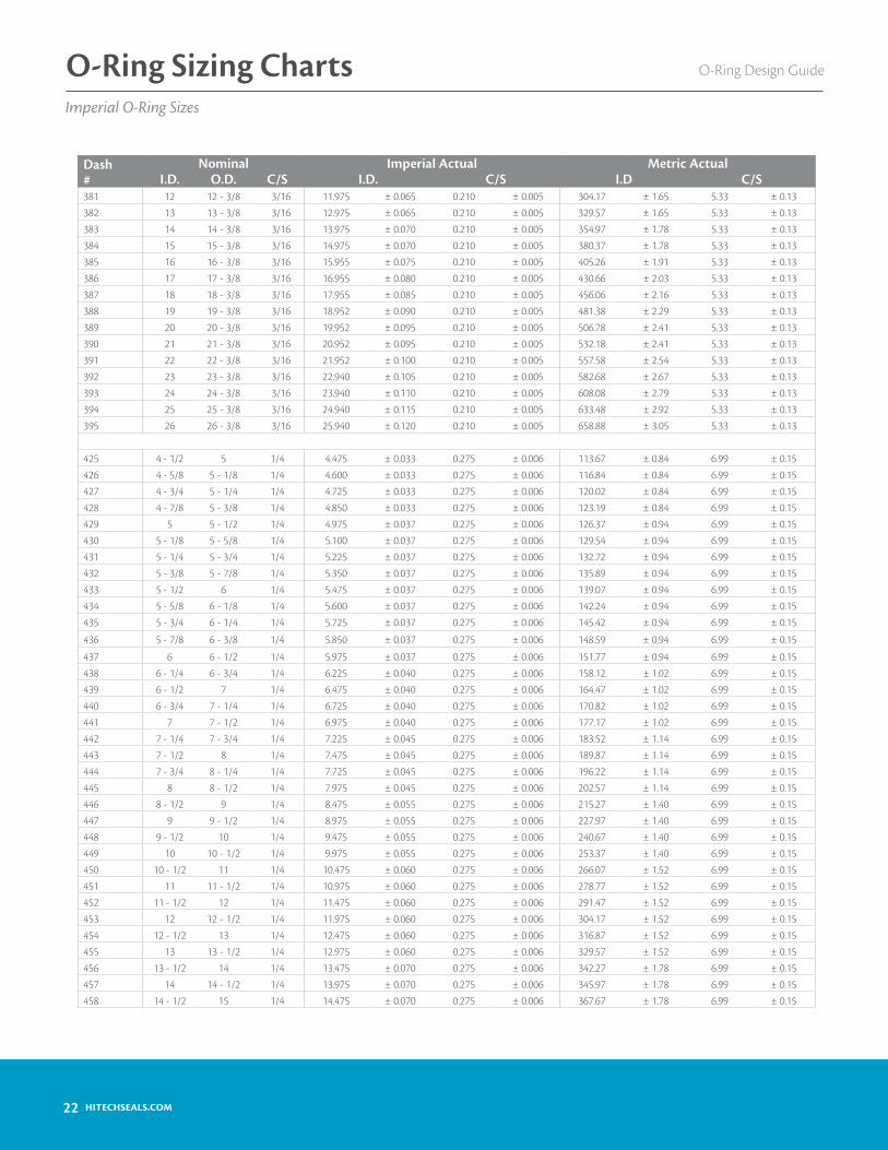
22 HITECHSEALS.COM
Dash #
Nominal Imperial Actual Metric ActualI.D. O.D. C/S I.D. C/S I.D C/S
381 12 12 - 3/8 3/16 11.975 ± 0.065 0.210 ± 0.005 304.17 ± 1.65 5.33 ± 0.13382 13 13 - 3/8 3/16 12.975 ± 0.065 0.210 ± 0.005 329.57 ± 1.65 5.33 ± 0.13383 14 14 - 3/8 3/16 13.975 ± 0.070 0.210 ± 0.005 354.97 ± 1.78 5.33 ± 0.13384 15 15 - 3/8 3/16 14.975 ± 0.070 0.210 ± 0.005 380.37 ± 1.78 5.33 ± 0.13385 16 16 - 3/8 3/16 15.955 ± 0.075 0.210 ± 0.005 405.26 ± 1.91 5.33 ± 0.13386 17 17 - 3/8 3/16 16.955 ± 0.080 0.210 ± 0.005 430.66 ± 2.03 5.33 ± 0.13387 18 18 - 3/8 3/16 17.955 ± 0.085 0.210 ± 0.005 456.06 ± 2.16 5.33 ± 0.13388 19 19 - 3/8 3/16 18.952 ± 0.090 0.210 ± 0.005 481.38 ± 2.29 5.33 ± 0.13389 20 20 - 3/8 3/16 19.952 ± 0.095 0.210 ± 0.005 506.78 ± 2.41 5.33 ± 0.13390 21 21 - 3/8 3/16 20.952 ± 0.095 0.210 ± 0.005 532.18 ± 2.41 5.33 ± 0.13391 22 22 - 3/8 3/16 21.952 ± 0.100 0.210 ± 0.005 557.58 ± 2.54 5.33 ± 0.13392 23 23 - 3/8 3/16 22.940 ± 0.105 0.210 ± 0.005 582.68 ± 2.67 5.33 ± 0.13393 24 24 - 3/8 3/16 23.940 ± 0.110 0.210 ± 0.005 608.08 ± 2.79 5.33 ± 0.13394 25 25 - 3/8 3/16 24.940 ± 0.115 0.210 ± 0.005 633.48 ± 2.92 5.33 ± 0.13395 26 26 - 3/8 3/16 25.940 ± 0.120 0.210 ± 0.005 658.88 ± 3.05 5.33 ± 0.13
425 4 - 1/2 5 1/4 4.475 ± 0.033 0.275 ± 0.006 113.67 ± 0.84 6.99 ± 0.15426 4 - 5/8 5 - 1/8 1/4 4.600 ± 0.033 0.275 ± 0.006 116.84 ± 0.84 6.99 ± 0.15427 4 - 3/4 5 - 1/4 1/4 4.725 ± 0.033 0.275 ± 0.006 120.02 ± 0.84 6.99 ± 0.15428 4 - 7/8 5 - 3/8 1/4 4.850 ± 0.033 0.275 ± 0.006 123.19 ± 0.84 6.99 ± 0.15429 5 5 - 1/2 1/4 4.975 ± 0.037 0.275 ± 0.006 126.37 ± 0.94 6.99 ± 0.15430 5 - 1/8 5 - 5/8 1/4 5.100 ± 0.037 0.275 ± 0.006 129.54 ± 0.94 6.99 ± 0.15431 5 - 1/4 5 - 3/4 1/4 5.225 ± 0.037 0.275 ± 0.006 132.72 ± 0.94 6.99 ± 0.15432 5 - 3/8 5 - 7/8 1/4 5.350 ± 0.037 0.275 ± 0.006 135.89 ± 0.94 6.99 ± 0.15433 5 - 1/2 6 1/4 5.475 ± 0.037 0.275 ± 0.006 139.07 ± 0.94 6.99 ± 0.15434 5 - 5/8 6 - 1/8 1/4 5.600 ± 0.037 0.275 ± 0.006 142.24 ± 0.94 6.99 ± 0.15435 5 - 3/4 6 - 1/4 1/4 5.725 ± 0.037 0.275 ± 0.006 145.42 ± 0.94 6.99 ± 0.15
436 5 - 7/8 6 - 3/8 1/4 5.850 ± 0.037 0.275 ± 0.006 148.59 ± 0.94 6.99 ± 0.15
437 6 6 - 1/2 1/4 5.975 ± 0.037 0.275 ± 0.006 151.77 ± 0.94 6.99 ± 0.15438 6 - 1/4 6 - 3/4 1/4 6.225 ± 0.040 0.275 ± 0.006 158.12 ± 1.02 6.99 ± 0.15439 6 - 1/2 7 1/4 6.475 ± 0.040 0.275 ± 0.006 164.47 ± 1.02 6.99 ± 0.15440 6 - 3/4 7 - 1/4 1/4 6.725 ± 0.040 0.275 ± 0.006 170.82 ± 1.02 6.99 ± 0.15441 7 7 - 1/2 1/4 6.975 ± 0.040 0.275 ± 0.006 177.17 ± 1.02 6.99 ± 0.15442 7 - 1/4 7 - 3/4 1/4 7.225 ± 0.045 0.275 ± 0.006 183.52 ± 1.14 6.99 ± 0.15443 7 - 1/2 8 1/4 7.475 ± 0.045 0.275 ± 0.006 189.87 ± 1.14 6.99 ± 0.15444 7 - 3/4 8 - 1/4 1/4 7.725 ± 0.045 0.275 ± 0.006 196.22 ± 1.14 6.99 ± 0.15445 8 8 - 1/2 1/4 7.975 ± 0.045 0.275 ± 0.006 202.57 ± 1.14 6.99 ± 0.15446 8 - 1/2 9 1/4 8.475 ± 0.055 0.275 ± 0.006 215.27 ± 1.40 6.99 ± 0.15447 9 9 - 1/2 1/4 8.975 ± 0.055 0.275 ± 0.006 227.97 ± 1.40 6.99 ± 0.15448 9 - 1/2 10 1/4 9.475 ± 0.055 0.275 ± 0.006 240.67 ± 1.40 6.99 ± 0.15449 10 10 - 1/2 1/4 9.975 ± 0.055 0.275 ± 0.006 253.37 ± 1.40 6.99 ± 0.15450 10 - 1/2 11 1/4 10.475 ± 0.060 0.275 ± 0.006 266.07 ± 1.52 6.99 ± 0.15451 11 11 - 1/2 1/4 10.975 ± 0.060 0.275 ± 0.006 278.77 ± 1.52 6.99 ± 0.15452 11 - 1/2 12 1/4 11.475 ± 0.060 0.275 ± 0.006 291.47 ± 1.52 6.99 ± 0.15453 12 12 - 1/2 1/4 11.975 ± 0.060 0.275 ± 0.006 304.17 ± 1.52 6.99 ± 0.15454 12 - 1/2 13 1/4 12.475 ± 0.060 0.275 ± 0.006 316.87 ± 1.52 6.99 ± 0.15455 13 13 - 1/2 1/4 12.975 ± 0.060 0.275 ± 0.006 329.57 ± 1.52 6.99 ± 0.15456 13 - 1/2 14 1/4 13.475 ± 0.070 0.275 ± 0.006 342.27 ± 1.78 6.99 ± 0.15457 14 14 - 1/2 1/4 13.975 ± 0.070 0.275 ± 0.006 345.97 ± 1.78 6.99 ± 0.15458 14 - 1/2 15 1/4 14.475 ± 0.070 0.275 ± 0.006 367.67 ± 1.78 6.99 ± 0.15
O-Ring Design GuideO-Ring Sizing ChartsImperial O-Ring Sizes

23HITECHSEALS.COM
O-Ring for Tube Fitting Bosses
Dash #
Nominal Actual Sizing Metric ActualI.D. O.D. C/S I.D. C/S I.D. C/S
459 15 15 - 1/2 1/4 14.975 ± 0.070 0.275 ± 0.006 380.37 ± 1.78 6.99 ± 0.15460 15 - 1/2 16 1/4 15.475 ± 0.070 0.275 ± 0.006 393.07 ± 1.78 6.99 ± 0.15461 16 16 - 1/2 1/4 15.955 ± 0.075 0.275 ± 0.006 405.26 ± 1.91 6.99 ± 0.15462 16 - 1/2 17 1/4 16.455 ± 0.075 0.275 ± 0.006 417.96 ± 1.91 6.99 ± 0.15463 17 17 - 1/2 1/4 16.955 ± 0.080 0.275 ± 0.006 430.66 ± 2.03 6.99 ± 0.15464 17 - 1/2 18 1/4 17.455 ± 0.085 0.275 ± 0.006 443.36 ± 2.16 6.99 ± 0.15465 18 18 - 1/2 1/4 17.955 ± 0.085 0.275 ± 0.006 456.06 ± 2.16 6.99 ± 0.15466 18 - 1/2 19 1/4 18.455 ± 0.085 0.275 ± 0.006 468.76 ± 2.16 6.99 ± 0.15467 19 19 - 1/2 1/4 18.955 ± 0.090 0.275 ± 0.006 481.46 ± 2.29 6.99 ± 0.15468 19 - 1/2 20 1/4 19.455 ± 0.090 0.275 ± 0.006 494.16 ± 2.29 6.99 ± 0.15469 20 20 - 1/2 1/4 19.955 ± 0.095 0.275 ± 0.006 506.86 ± 2.41 6.99 ± 0.15470 21 21 - 1/2 1/4 20.955 ± 0.095 0.275 ± 0.006 532.26 ± 2.41 6.99 ± 0.15471 22 22 - 1/2 1/4 21.955 ± 0.100 0.275 ± 0.006 557.66 ± 2.54 6.99 ± 0.15472 23 23 - 1/2 1/4 22.940 ± 0.105 0.275 ± 0.006 582.68 ± 2.67 6.99 ± 0.15473 24 24 - 1/2 1/4 23.940 ± 0.110 0.275 ± 0.006 608.08 ± 2.79 6.99 ± 0.15474 25 25 - 1/2 1/4 24.940 ± 0.115 0.275 ± 0.006 633.48 ± 2.92 6.99 ± 0.15475 26 26 - 1/2 1/4 25.940 ± 0.120 0.275 ± 0.006 658.88 ± 3.05 6.99 ± 0.15
Dash #
Tube SizeOD Inch
Hydraulic MIL-P-5570
MS28778
Actual Sizing Metric Actual
I.D. C/S I.D. C/S
901 3/32 0.185 ± 0.005 0.056 ± 0.003 4.70 ± 0.13 1.42 ± 0.08902 1/8 2 0.239 ± 0.005 0.064 ± 0.003 6.07 ± 0.13 1.63 ± 0.08903 3/16 3 0.301 ± 0.005 0.064 ± 0.003 7.65 ± 0.13 1.63 ± 0.08904 1/4 4 0.351 ± 0.005 0.072 ± 0.003 8.92 ± 0.13 1.83 ± 0.08905 5/16 5 0.414 ± 0.005 0.072 ± 0.003 10.52 ± 0.13 1.83 ± 0.08906 3/8 6 0.468 ± 0.005 0.078 ± 0.003 11.89 ± 0.13 1.98 ± 0.08907 7/16 0.530 ± 0.005 0.082 ± 0.003 13.46 ± 0.13 2.08 ± 0.08908 1/2 8 0.644 ± 0.009 0.087 ± 0.003 16.36 ± 0.23 2.21 ± 0.08909 9/16 0.706 ± 0.009 0.097 ± 0.003 17.93 ± 0.23 2.46 ± 0.08910 5/8 10 0.755 ± 0.009 0.097 ± 0.003 19.18 ± 0.23 2.46 ± 0.08911 11/16 0.863 ± 0.009 0.116 ± 0.004 21.92 ± 0.23 2.95 ± 0.10912 3/4 12 0.924 ± 0.009 0.116 ± 0.004 23.47 ± 0.23 2.95 ± 0.10
913 13/16 0.986 ± 0.010 0.116 ± 0.004 25.04 ± 0.25 2.95 ± 0.10
914 7/8 14 1.048 ± 0.010 0.116 ± 0.004 26.62 ± 0.25 2.95 ± 0.10916 1 16 1.171 ± 0.010 0.116 ± 0.004 29.74 ± 0.25 2.95 ± 0.10918 1-1/8 1.355 ± 0.012 0.116 ± 0.004 34.42 ± 0.30 2.95 ± 0.10920 1-1/4 20 1.475 ± 0.014 0.118 ± 0.004 37.47 ± 0.36 3.00 ± 0.10924 1-1/2 24 1.720 ± 0.014 0.118 ± 0.004 43.69 ± 0.36 3.00 ± 0.10
928 1-3/4 28 2.090 ± 0.018 0.118 ± 0.004 53.09 ± 0.36 3.00 ± 0.10
932 2 32 2.337 ± 0.018 0.118 ± 0.004 59.36 ± 0.36 3.00 ± 0.10
We offer O-rings in sizes ranging from 400-424. These O-ring size dimensions and tolerances are unassigned under ISO 3601. In addi-tion, Hi-Tech Seals stocks specific non-standard cross-section O-rings such as 3/8”, 1/2” and 3/4”.
O-Ring Design Guide O-Ring Sizing ChartsImperial O-Ring Sizes

24 HITECHSEALS.COM
O-Ring Design GuideO-Ring Sizing ChartsMetric O-Ring Sizes
PartNumber C/S I.D.
Cross Ref. #
1000115 1.00 1.151000125 1.00 1.25100015 1.00 1.50100018 1.00 1.8010002 1.00 2.00100025 1.00 2.50100027 1.00 2.7010003 1.00 3.00100033 1.00 3.30100035 1.00 3.5010004 1.00 4.00100045 1.00 4.5010005 1.00 5.00100055 1.00 5.5010006 1.00 6.00100065 1.00 6.5010007 1.00 7.00100072 1.00 7.20100075 1.00 7.5010008 1.00 8.00100085 1.00 8.5010009 1.00 9.00100095 1.00 9.5010010 1.00 10.00100105 1.00 10.5010011 1.00 11.00100115 1.00 11.5010012 1.00 12.00100125 1.00 12.5010013 1.00 13.00100135 1.00 13.5010014 1.00 14.00100145 1.00 14.5010015 1.00 15.00100155 1.00 15.5010016 1.00 16.00100165 1.00 16.5010017 1.00 17.0010018 1.00 18.00100185 1.00 18.5010019 1.00 19.00100195 1.00 19.50
10020 1.00 20.00
PartNumber C/S I.D.
Cross Ref. #
100205 1.00 20.5010021 1.00 21.00100215 1.00 21.5010022 1.00 22.00100225 1.00 22.5010023 1.00 23.00100235 1.00 23.5010024 1.00 24.00100245 1.00 24.5010025 1.00 25.0010028 1.00 28.00100294 1.00 29.40100299 1.00 29.90100305 1.00 30.50100318 1.00 31.8010032 1.00 32.0010039 1.00 39.0010042 1.00 42.0010060 1.00 60.00-001 1.02 0.74 -001120025 1.20 2.50120026 1.20 2.60120035 1.20 3.5012005 1.20 5.0012024 1.20 24.0012026 1.20 26.0012028 1.20 28.0012035 1.20 35.0012040 1.20 40.00120535 1.20 53.5012098 1.20 98.00-002 1.27 1.07 -002150018 1.50 1.801500185 1.50 1.8515002 1.50 2.00150025 1.50 2.50 S 3150028 1.50 2.8015003 1.50 3.00150035 1.50 3.50 S 415004 1.50 4.00150045 1.50 4.50 S 515005 1.50 5.00150055 1.50 5.50 S 6
PartNumber C/S I.D.
Cross Ref. #
15006 1.50 6.00150065 1.50 6.50 S 715007 1.50 7.00150075 1.50 7.50 S 815008 1.50 8.00150085 1.50 8.50 S 915009 1.50 9.00150095 1.50 9.50 S 1015010 1.50 10.00150105 1.50 10.50150107 1.50 10.70 S 11.215011 1.50 11.00150115 1.50 11.50 S 1215012 1.50 12.00 S 12.5150125 1.50 12.5015013 1.50 13.001501325 1.50 13.25150135 1.50 13.50 S 1415014 1.50 14.0015015 1.50 15.00150155 1.50 15.50 S 1615016 1.50 16.00150165 1.50 16.5015017 1.50 17.00150175 1.50 17.50 S 1815018 1.50 18.00150185 1.50 18.5015019 1.50 19.00150195 1.50 19.50 S 2015020 1.50 20.00150205 1.50 20.5015021 1.50 21.00150215 1.50 21.5 S 2215022 1.50 22.00150225 1.50 22.5015023 1.50 23.00150235 1.50 23.5015024 1.50 24.00150245 1.50 24.5015025 1.50 25.00150255 1.50 25.5015026 1.50 26.00150265 1.50 26.50
I.D.
C/S

25HITECHSEALS.COM
O-Ring Design Guide O-Ring Sizing ChartsMetric O-Ring Sizes
PartNumber C/S I.D.
Cross Ref. #
15027 1.50 27.00150275 1.50 27.5015028 1.50 28.00150285 1.50 28.5015029 1.50 29.00150295 1.50 29.5015030 1.50 30.00150305 1.50 30.5015031 1.50 31.00150315 1.50 31.5015032 1.50 32.00150325 1.50 32.5015033 1.50 33.00150335 1.50 33.5015034 1.50 34.00150345 1.50 34.5015035 1.50 35.00150355 1.50 35.5015036 1.50 36.00150365 1.50 36.5015037 1.50 37.00150375 1.50 37.5015038 1.50 38.00150385 1.50 38.5015039 1.50 39.00150395 1.50 39.5015040 1.50 40.0015041 1.50 41.0015042 1.50 42.0015043 1.50 43.0015044 1.50 44.0015045 1.50 45.0015046 1.50 46.0015047 1.50 47.0015048 1.50 48.0015049 1.50 49.0015050 1.50 50.0015051 1.50 51.0015052 1.50 52.0015053 1.50 53.0015054 1.50 54.0015055 1.50 55.0015056 1.50 56.0015057 1.50 57.0015058 1.50 58.0015059 1.50 59.0015060 1.50 60.0015061 1.50 61.0015062 1.50 62.0015063 1.50 63.0015064 1.50 64.00
PartNumber C/S I.D.
Cross Ref. #
15065 1.50 65.0015066 1.50 66.0015067 1.50 67.0015068 1.50 68.0015069 1.50 69.0015070 1.50 70.0015071 1.50 71.0015072 1.50 72.0015073 1.50 73.0015074 1.50 74.0015075 1.50 75.0015076 1.50 76.0015077 1.50 77.0015078 1.50 78.0015079 1.50 79.0015080 1.50 80.0015081 1.50 81.0015082 1.50 82.0015083 1.50 83.0015084 1.50 84.0015085 1.50 85.0015086 1.50 86.0015087 1.50 87.0015088 1.50 88.0015089 1.50 89.0015090 1.50 90.0015091 1.50 91.0015092 1.50 92.0015093 1.50 93.0015094 1.50 94.0015095 1.50 95.0015096 1.50 96.0015097 1.50 97.0015098 1.50 98.0015099 1.50 99.0015100 1.50 100.0015105 1.50 105.0015145 1.50 145.00-003 1.52 1.42 -003160022 1.60 2.201600275 1.60 2.75160028 1.60 2.80160031 1.60 3.10160032 1.60 3.20160037 1.60 3.70160041 1.60 4.10160047 1.60 4.70160050 1.60 5.00160051 1.60 5.10160061 1.60 6.10160068 1.60 6.80
PartNumber C/S I.D.
Cross Ref. #
160071 1.60 7.10160081 1.60 8.10160091 1.60 9.10160101 1.60 10.10160111 1.60 11.10160121 1.60 12.10160131 1.60 13.10160141 1.60 14.10160151 1.60 15.10160161 1.60 16.10160171 1.60 17.10160181 1.60 18.10160191 1.60 19.10160203 1.60 20.30160211 1.60 21.10160221 1.60 22.10160251 1.60 25.10160271 1.60 27.10160291 1.60 29.10160321 1.60 32.10160351 1.60 35.10160371 1.60 37.10160511 1.60 51.10160860 1.60 86.00160966 1.60 96.6016115 1.60 115.00-004 1.78 1.78 -004-005 1.78 2.57 -005-006 1.78 2.90 -006-007 1.78 3.68 -007-008 1.78 4.47 -008-009 1.78 5.28 -009-010 1.78 6.07 -010-011 1.78 7.65 -011-012 1.78 9.25 -012-013 1.78 10.82 -013-014 1.78 12.42 -014-015 1.78 14.00 -015-016 1.78 15.60 -016-017 1.78 17.17 -017-018 1.78 18.77 -018-019 1.78 20.35 -019-020 1.78 21.95 -020-021 1.78 23.52 -021-022 1.78 25.12 -022-023 1.78 26.70 -023-024 1.78 28.30 -024-025 1.78 29.87 -025-026 1.78 31.47 -026-027 1.78 33.05 -027-028 1.78 34.65 -028

26 HITECHSEALS.COM
O-Ring Design GuideO-Ring Sizing ChartsMetric O-Ring Sizes
PartNumber C/S I.D.
Cross Ref. #
-029 1.78 37.82 -029-030 1.78 41.00 -030-031 1.78 44.17 -031-032 1.78 47.35 -032-033 1.78 50.52 -033-034 1.78 53.70 -034-035 1.78 56.87 -035-036 1.78 60.05 -036-037 1.78 63.22 -037-038 1.78 66.40 -038-039 1.78 69.57 -039-040 1.78 72.75 -040-041 1.78 75.92 -041-042 1.78 82.27 -042-043 1.78 88.62 -043-044 1.78 94.97 -044-045 1.78 101.32 -045-046 1.78 107.67 -046-047 1.78 114.02 -047-048 1.78 120.37 -048-049 1.78 126.72 -049-050 1.78 133.07 -050180018 1.80 1.8018002 1.80 2.001800224 1.80 2.24180025 1.80 2.50180028 1.80 2.801800315 1.80 3.151800355 1.80 3.551800375 1.80 3.7518004 1.80 4.00180045 1.80 4.501800487 1.80 4.8718005 1.80 5.001800515 1.80 5.15180053 1.80 5.30180056 1.80 5.6018006 1.80 6.00180063 1.80 6.30180067 1.80 6.70180069 1.80 6.90180071 1.80 7.10180075 1.80 7.5018008 1.80 8.00180085 1.80 8.501800876 1.80 8.7618009 1.80 9.00180095 1.80 9.5018010 1.80 10.00180106 1.80 10.60180112 1.80 11.20
PartNumber C/S I.D.
Cross Ref. #
180118 1.80 11.80180125 1.80 12.50180132 1.80 13.2018014 1.80 14.0018015 1.80 15.0018016 1.80 16.0018017 1.80 17.00190024 1.90 2.40190026 1.90 2.60190028 1.90 2.80 P 3190034 1.90 3.40190037 1.90 3.70190038 1.90 3.80 P 4190042 1.90 4.20190048 1.90 4.80 P 5190049 1.90 4.90190057 1.90 5.70190058 1.90 5.80 P 6190064 1.90 6.40190068 1.90 6.80 P 7190072 1.90 7.20190078 1.90 7.80 P 819008 1.90 8.00190088 1.90 8.80 P 9190089 1.90 8.90190098 1.90 9.80 P 1020002 2.00 2.00200025 2.00 2.50200026 2.00 2.6020003 2.00 3.00200035 2.00 3.5020004 2.00 4.00200045 2.00 4.50200046 2.00 4.6020005 2.00 5.00200055 2.00 5.5020006 2.00 6.00200065 2.00 6.5020007 2.00 7.00200075 2.00 7.5020008 2.00 8.00200085 2.00 8.5020009 2.00 9.00200094 2.00 9.4020010 2.00 10.00200105 2.00 10.5020011 2.00 11.00200115 2.00 11.5020012 2.00 12.00200125 2.00 12.5020013 2.00 13.00
PartNumber C/S I.D.
Cross Ref. #
200135 2.00 13.5020014 2.00 14.00200145 2.00 14.5020015 2.00 15.00200155 2.00 15.5020016 2.00 16.00200165 2.00 16.5020017 2.00 17.00200175 2.00 17.5020018 2.00 18.00200185 2.00 18.5020019 2.00 19.00200195 2.00 19.5020020 2.00 20.00200205 2.00 20.5020021 2.00 21.00200215 2.00 21.50200219 2.00 21.90 S 22.420022 2.00 22.00200225 2.00 22.5020023 2.00 23.00200235 2.00 23.50 S 2420024 2.00 24.00200245 2.00 24.50 S 2520025 2.00 25.00200255 2.00 25.50 S 2620026 2.00 26.00200265 2.00 26.5020027 2.00 27.00200275 2.00 27.50 S 2820028 2.00 28.00200285 2.00 28.50 S 2920029 2.00 29.00200295 2.00 29.50 S 3020030 2.00 30.00200305 2.00 30.5020031 2.00 31.00 S 31.5200315 2.00 31.50 S 3220032 2.00 32.00200325 2.00 32.5020033 2.00 33.00200335 2.00 33.50 S 3420034 2.00 34.00200345 2.00 34.50 S 3520035 2.00 35.00 S 35.5200355 2.00 35.50 S 3620036 2.00 36.00200365 2.00 36.5020037 2.00 37.00200375 2.00 37.50 S 3820038 2.00 38.00
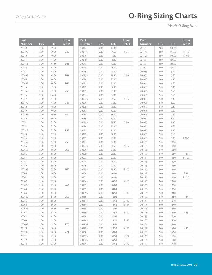
27HITECHSEALS.COM
O-Ring Design Guide O-Ring Sizing ChartsMetric O-Ring Sizes
PartNumber C/S I.D.
Cross Ref. #
20039 2.00 39.00200395 2.00 39.50 S 4020040 2.00 40.0020041 2.00 41.00200415 2.00 41.50 S 4220042 2.00 42.0020043 2.00 43.00200435 2.00 43.50 S 4420044 2.00 44.00200445 2.00 44.50 S 4520045 2.00 45.00200455 2.00 45.50 S 4620046 2.00 46.0020047 2.00 47.00200475 2.00 47.50 S 4820048 2.00 48.0020049 2.00 49.00200495 2.00 49.50 S 5020050 2.00 50.0020051 2.00 51.0020052 2.00 52.00200525 2.00 52.50 S 5320053 2.00 53.0020054 2.00 54.00200545 2.00 54.50 S 5520055 2.00 55.00200555 2.00 55.50 S 5620056 2.00 56.0020057 2.00 57.0020058 2.00 58.0020059 2.00 59.00200595 2.00 59.50 S 6020060 2.00 60.0020061 2.00 61.0020062 2.00 62.00200625 2.00 62.50 S 6320063 2.00 63.0020064 2.00 64.00200645 2.00 64.50 S 6520065 2.00 65.0020066 2.00 66.00200665 2.00 66.50 S 6720067 2.00 67.0020068 2.00 68.0020069 2.00 69.00200695 2.00 69.50 S 7020070 2.00 70.00200705 2.00 70.50 S 7120071 2.00 71.0020072 2.00 72.0020073 2.00 73.00
PartNumber C/S I.D.
Cross Ref. #
20074 2.00 74.00200745 2.00 74.50 S 7520075 2.00 75.0020076 2.00 76.0020077 2.00 77.0020078 2.00 78.0020079 2.00 79.00200795 2.00 79.50 S 8020080 2.00 80.0020081 2.00 81.0020082 2.00 82.0020083 2.00 83.0020084 2.00 84.00200845 2.00 84.50 S 8520085 2.00 85.0020086 2.00 86.0020087 2.00 87.0020088 2.00 88.0020089 2.00 89.00200895 2.00 89.50 S 9020090 2.00 90.0020091 2.00 91.0020092 2.00 92.0020093 2.00 93.0020094 2.00 94.00200945 2.00 94.50 S 9520095 2.00 95.0020096 2.00 96.0020097 2.00 97.0020098 2.00 98.0020099 2.00 99.00200995 2.00 99.50 S 10020100 2.00 100.0020102 2.00 102.00201045 2.00 104.50 S 10520105 2.00 105.0020109 2.00 109.00201095 2.00 109.50 S 11020110 2.00 110.00201115 2.00 111.50 S 112201145 2.00 114.50 S 11520115 2.00 115.00201195 2.00 119.50 S 12020120 2.00 120.00201245 2.00 124.50 S 125201256 2.00 125.60201295 2.00 129.50 S 13020130 2.00 130.00201315 2.00 131.50 S 132201345 2.00 134.50 S 135201395 2.00 139.50 S 140
PartNumber C/S I.D.
Cross Ref. #
20140 2.00 140.00201445 2.00 144.50 S 145201495 2.00 149.50 S 15020165 2.00 165.0020180 2.00 180.0020194 2.00 194.00240033 2.40 3.30240036 2.40 3.60240043 2.40 4.30240046 2.40 4.60240053 2.40 5.30240055 2.40 5.50240056 2.40 5.60240063 2.40 6.30240066 2.40 6.60240073 2.40 7.30240075 2.40 7.50240076 2.40 7.6024008 2.40 8.00240083 2.40 8.30240086 2.40 8.60240093 2.40 9.30240096 2.40 9.60240098 2.40 9.80 P 10A240103 2.40 10.30240105 2.40 10.50240106 2.40 10.60240108 2.40 10.80 P 1124011 2.40 11.00 P 11.2240113 2.40 11.30240115 2.40 11.50240116 2.40 11.60240118 2.40 11.80 P 12240123 2.40 12.30 P 12.5240126 2.40 12.60240133 2.40 13.30240135 2.40 13.50240136 2.40 13.60240138 2.40 13.80 P 14240143 2.40 14.30240145 2.40 14.50240146 2.40 14.60240148 2.40 14.80 P 15240153 2.40 15.30240155 2.40 15.50240156 2.40 15.60240158 2.40 15.80 P 16240159 2.40 15.90240163 2.40 16.30240166 2.40 16.60240173 2.40 17.30

28 HITECHSEALS.COM
O-Ring Design GuideO-Ring Sizing ChartsMetric O-Ring Sizes
PartNumber C/S I.D.
Cross Ref. #
240175 2.40 17.50240176 2.40 17.60240178 2.40 17.80 P 18240183 2.40 18.30240186 2.40 18.60240193 2.40 19.30240196 2.40 19.60240198 2.40 19.80 P 20240203 2.40 20.30240205 2.40 20.50240208 2.40 20.80 P 21240213 2.40 21.30240215 2.40 21.50240216 2.40 21.60240218 2.40 21.80 P 22240223 2.40 22.30240226 2.40 22.60240233 2.40 23.30240235 2.40 23.50240236 2.40 23.60240243 2.40 24.30240245 2.40 24.50240246 2.40 24.6024025 2.40 25.00240253 2.40 25.30240256 2.40 25.60240273 2.40 27.30240275 2.40 27.50240276 2.40 27.60240296 2.40 29.60240303 2.40 30.30240316 2.40 31.60240333 2.40 33.30240346 2.40 34.60240365 2.40 36.50240376 2.40 37.60240396 2.40 39.60240416 2.40 41.60240446 2.40 44.60240476 2.40 47.60240496 2.40 49.60240516 2.40 51.60240546 2.40 54.60240576 2.40 57.60240596 2.40 59.60240616 2.40 61.60240646 2.40 64.60240676 2.40 67.60240696 2.40 69.6025004 2.50 4.00250046 2.50 4.60
PartNumber C/S I.D.
Cross Ref. #
25005 2.50 5.00250055 2.50 5.5025006 2.50 6.00250065 2.50 6.5025007 2.50 7.00250075 2.50 7.5025008 2.50 8.00250085 2.50 8.5025009 2.50 9.00250095 2.50 9.5025010 2.50 10.00250105 2.50 10.5025011 2.50 11.00250115 2.50 11.5025012 2.50 12.00250125 2.50 12.5025013 2.50 13.00250135 2.50 13.5025014 2.50 14.00250145 2.50 14.5025015 2.50 15.00250155 2.50 15.5025016 2.50 16.00250165 2.50 16.5025017 2.50 17.00250175 2.50 17.5025018 2.50 18.00250185 2.50 18.5025019 2.50 19.00250195 2.50 19.5025020 2.50 20.00250205 2.50 20.5025021 2.50 21.00250215 2.50 21.5025022 2.50 22.00250225 2.50 22.5025023 2.50 23.00250235 2.50 23.5025024 2.50 24.00250245 2.50 24.5025025 2.50 25.00250255 2.50 25.5025026 2.50 26.00250265 2.50 26.5025027 2.50 27.00250275 2.50 27.5025028 2.50 28.00250285 2.50 28.5025029 2.50 29.00250295 2.50 29.5025030 2.50 30.00
PartNumber C/S I.D.
Cross Ref. #
250305 2.50 30.5025031 2.50 31.00250315 2.50 31.5025032 2.50 32.00250325 2.50 32.5025033 2.50 33.00250335 2.50 33.5025034 2.50 34.00250345 2.50 34.5025035 2.50 35.00250355 2.50 35.5025036 2.50 36.00250365 2.50 36.5025037 2.50 37.00250375 2.50 37.5025038 2.50 38.00250385 2.50 38.5025039 2.50 39.00250395 2.50 39.5025040 2.50 40.0025041 2.50 41.0025042 2.50 42.0025043 2.50 43.0025044 2.50 44.0025045 2.50 45.0025046 2.50 46.0025047 2.50 47.0025048 2.50 48.0025049 2.50 49.0025050 2.50 50.0025051 2.50 51.0025052 2.50 52.0025053 2.50 53.0025054 2.50 54.0025055 2.50 55.0025056 2.50 56.0025057 2.50 57.0025058 2.50 58.0025059 2.50 59.0025060 2.50 60.0025061 2.50 61.0025062 2.50 62.0025063 2.50 63.0025064 2.50 64.0025065 2.50 65.0025066 2.50 66.0025067 2.50 67.0025068 2.50 68.0025069 2.50 69.0025070 2.50 70.0025071 2.50 71.00

29HITECHSEALS.COM
O-Ring Design Guide O-Ring Sizing ChartsMetric O-Ring Sizes
PartNumber C/S I.D.
Cross Ref. #
25072 2.50 72.0025073 2.50 73.0025074 2.50 74.0025075 2.50 75.0025076 2.50 76.0025077 2.50 77.0025078 2.50 78.0025079 2.50 79.0025080 2.50 80.0025081 2.50 81.0025082 2.50 82.0025083 2.50 83.0025084 2.50 84.0025085 2.50 85.0025086 2.50 86.0025087 2.50 87.0025088 2.50 88.0025089 2.50 89.0025090 2.50 90.0025091 2.50 91.0025092 2.50 92.0025093 2.50 93.0025094 2.50 94.0025095 2.50 95.0025096 2.50 96.0025097 2.50 97.0025098 2.50 98.0025099 2.50 99.0025100 2.50 100.0025101 2.50 101.0025102 2.50 102.0025103 2.50 103.0025104 2.50 104.0025105 2.50 105.0025106 2.50 106.0025107 2.50 107.0025108 2.50 108.0025109 2.50 109.0025110 2.50 110.0025111 2.50 111.0025112 2.50 112.0025113 2.50 113.0025114 2.50 114.0025115 2.50 115.0025116 2.50 116.0025117 2.50 117.0025118 2.50 118.0025119 2.50 119.0025120 2.50 120.0025121 2.50 121.0025122 2.50 122.00
PartNumber C/S I.D.
Cross Ref. #
25123 2.50 123.0025124 2.50 124.0025125 2.50 125.0025126 2.50 126.0025127 2.50 127.0025128 2.50 128.0025129 2.50 129.0025130 2.50 130.0025131 2.50 131.0025132 2.50 132.0025133 2.50 133.0025134 2.50 134.0025135 2.50 135.0025136 2.50 136.0025137 2.50 137.0025138 2.50 138.0025139 2.50 139.0025140 2.50 140.0025141 2.50 141.0025142 2.50 142.0025143 2.50 143.0025144 2.50 144.0025145 2.50 145.0025146 2.50 146.0025147 2.50 147.0025148 2.50 148.0025149 2.50 149.0025150 2.50 150.00-102 2.62 1.24 -102-103 2.62 2.06 -103-104 2.62 2.84 -104-105 2.62 3.63 -105-106 2.62 4.42 -106-107 2.62 5.23 -107-108 2.62 6.02 -108-109 2.62 7.59 -109-110 2.62 9.19 -110-111 2.62 10.77 -111-112 2.62 12.37 -112-113 2.62 13.94 -113-114 2.62 15.54 -114-115 2.62 17.12 -115-116 2.62 18.72 -116-117 2.62 20.30 -117-118 2.62 21.89 -118-119 2.62 23.47 -119-120 2.62 25.07 -120-121 2.62 26.64 -121-122 2.62 28.24 -122-123 2.62 29.82 -123-124 2.62 31.42 -124
PartNumber C/S I.D.
Cross Ref. #
-125 2.62 32.99 -125-126 2.62 34.59 -126-127 2.62 36.17 -127-128 2.62 37.77 -128-129 2.62 39.34 -129-130 2.62 40.94 -130-131 2.62 42.52 -131-132 2.62 44.12 -132-133 2.62 45.69 -133-134 2.62 47.29 -134-135 2.62 48.90 -135-136 2.62 50.47 -136-137 2.62 52.07 -137-138 2.62 53.64 -138-139 2.62 55.25 -139-140 2.62 56.82 -140-141 2.62 58.42 -141-142 2.62 59.99 -142-143 2.62 61.60 -143-144 2.62 63.17 -144-145 2.62 64.77 -145-146 2.62 66.34 -146-147 2.62 67.95 -147-148 2.62 69.52 -148-149 2.62 71.12 -149-150 2.62 72.69 -150-151 2.62 75.87 -151-152 2.62 82.22 -152-153 2.62 88.57 -153-154 2.62 94.92 -154-155 2.62 101.27 -155-156 2.62 107.62 -156-157 2.62 113.97 -157-158 2.62 120.32 -158-159 2.62 126.67 -159-160 2.62 133.02 -160-161 2.62 139.37 -161-162 2.62 145.72 -162-163 2.62 152.07 -163-164 2.62 158.42 -164-165 2.62 164.77 -165-166 2.62 171.12 -166-167 2.62 177.47 -167-168 2.62 183.82 -168-169 2.62 190.17 -169-170 2.62 196.52 -170-171 2.62 202.87 -171-172 2.62 209.22 -172-173 2.62 215.57 -173-174 2.62 221.92 -174-175 2.62 228.27 -175
30 HITECHSEALS.COM
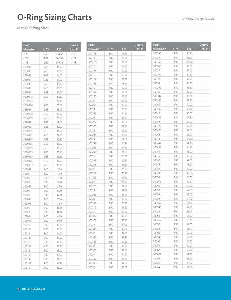
O-Ring Design GuideO-Ring Sizing ChartsMetric O-Ring Sizes
PartNumber C/S I.D.
Cross Ref. #
-176 2.62 234.62 -176-177 2.62 240.97 -177-178 2.62 247.32 -178265014 2.65 14.00265015 2.65 15.00265016 2.65 16.00265017 2.65 17.00265018 2.65 18.00265019 2.65 19.00265020 2.65 20.002650212 2.65 21.202650224 2.65 22.402650236 2.65 23.60265025 2.65 25.002650258 2.65 25.802650265 2.65 26.50265028 2.65 28.00265030 2.65 30.002650315 2.65 31.50265032 2.65 32.002650325 2.65 32.502650335 2.65 33.502650345 2.65 34.502650355 2.65 35.502650365 2.65 36.502650375 2.65 37.502650387 2.65 38.70300035 3.00 3.5030004 3.00 4.00300045 3.00 4.5030005 3.00 5.00300055 3.00 5.5030006 3.00 6.00300065 3.00 6.5030007 3.00 7.00300075 3.00 7.5030008 3.00 8.00300085 3.00 8.5030009 3.00 9.00300095 3.00 9.5030010 3.00 10.00300105 3.00 10.5030011 3.00 11.00300115 3.00 11.5030012 3.00 12.00300125 3.00 12.5030013 3.00 13.00300135 3.00 13.5030014 3.00 14.00300145 3.00 14.5030015 3.00 15.00
PartNumber C/S I.D.
Cross Ref. #
300155 3.00 15.5030016 3.00 16.00300165 3.00 16.5030017 3.00 17.00300175 3.00 17.5030018 3.00 18.00300182 3.00 18.20300185 3.00 18.5030019 3.00 19.00300192 3.00 19.20300195 3.00 19.5030020 3.00 20.00300205 3.00 20.5030021 3.00 21.00300215 3.00 21.5030022 3.00 22.00300222 3.00 22.20300225 3.00 22.5030023 3.00 23.00300235 3.00 23.5030024 3.00 24.00300242 3.00 24.20300245 3.00 24.50300246 3.00 24.6030025 3.00 25.00300252 3.00 25.20300255 3.00 25.5030026 3.00 26.00300262 3.00 26.20300265 3.00 26.5030027 3.00 27.00300275 3.00 27.5030028 3.00 28.00300285 3.00 28.5030029 3.00 29.00300292 3.00 29.20300295 3.00 29.5030030 3.00 30.00300302 3.00 30.20300305 3.00 30.5030031 3.00 31.00300315 3.00 31.5030032 3.00 32.00300322 3.00 32.20300325 3.00 32.5030033 3.00 33.00300335 3.00 33.5030034 3.00 34.00300342 3.00 34.20300345 3.00 34.5030035 3.00 35.00
PartNumber C/S I.D.
Cross Ref. #
300355 3.00 35.5030036 3.00 36.00300362 3.00 36.20300365 3.00 36.5030037 3.00 37.00300372 3.00 37.20300375 3.00 37.5030038 3.00 38.00300385 3.00 38.5030039 3.00 39.00300392 3.00 39.20300395 3.00 39.5030040 3.00 40.00300402 3.00 40.2030041 3.00 41.00300415 3.00 41.5030042 3.00 42.00300422 3.00 42.20300425 3.00 42.5030043 3.00 43.0030044 3.00 44.00300442 3.00 44.20300445 3.00 44.5030045 3.00 45.0030046 3.00 46.0030047 3.00 47.0030048 3.00 48.0030049 3.00 49.00300495 3.00 49.5030050 3.00 50.00300505 3.00 50.5030051 3.00 51.0030052 3.00 52.0030053 3.00 53.0030054 3.00 54.00300542 3.00 54.20300545 3.00 54.5030055 3.00 55.0030056 3.00 56.00300562 3.00 56.2030057 3.00 57.0030058 3.00 58.0030059 3.00 59.00300595 3.00 59.5030060 3.00 60.0030061 3.00 61.0030062 3.00 62.00300622 3.00 62.2030063 3.00 63.0030064 3.00 64.00300645 3.00 64.50

31HITECHSEALS.COM
O-Ring Design Guide O-Ring Sizing ChartsMetric O-Ring Sizes
PartNumber C/S I.D.
Cross Ref. #
30065 3.00 65.0030066 3.00 66.0030067 3.00 67.0030068 3.00 68.0030069 3.00 69.0030070 3.00 70.0030071 3.00 71.0030072 3.00 72.0030073 3.00 73.0030074 3.00 74.0030075 3.00 75.0030076 3.00 76.0030077 3.00 77.0030078 3.00 78.0030079 3.00 79.0030080 3.00 80.0030081 3.00 81.0030082 3.00 82.0030083 3.00 83.0030084 3.00 84.00300845 3.00 84.5030085 3.00 85.0030086 3.00 86.0030087 3.00 87.0030088 3.00 88.0030089 3.00 89.00300895 3.00 89.5030090 3.00 90.0030091 3.00 91.0030092 3.00 92.0030093 3.00 93.0030094 3.00 94.00300945 3.00 94.5030095 3.00 95.0030096 3.00 96.0030097 3.00 97.0030098 3.00 98.0030099 3.00 99.00300995 3.00 99.5030100 3.00 100.0030101 3.00 101.0030102 3.00 102.0030103 3.00 103.0030104 3.00 104.00301045 3.00 104.5030105 3.00 105.0030106 3.00 106.0030107 3.00 107.0030108 3.00 108.0030109 3.00 109.00301095 3.00 109.50
PartNumber C/S I.D.
Cross Ref. #
30110 3.00 110.0030111 3.00 111.0030112 3.00 112.0030113 3.00 113.0030114 3.00 114.00301145 3.00 114.5030115 3.00 115.0030116 3.00 116.0030117 3.00 117.0030118 3.00 118.0030119 3.00 119.00301195 3.00 119.5030120 3.00 120.0030121 3.00 121.0030122 3.00 122.0030123 3.00 123.0030124 3.00 124.00301245 3.00 124.5030125 3.00 125.0030126 3.00 126.00301265 3.00 126.5030127 3.00 127.0030128 3.00 128.0030129 3.00 129.00301295 3.00 129.5030130 3.00 130.0030131 3.00 131.0030132 3.00 132.0030133 3.00 133.0030134 3.00 134.00301345 3.00 134.5030135 3.00 135.0030136 3.00 136.0030137 3.00 137.0030138 3.00 138.0030139 3.00 139.00301395 3.00 139.5030140 3.00 140.0030141 3.00 141.0030142 3.00 142.0030143 3.00 143.0030144 3.00 144.00301445 3.00 144.5030145 3.00 145.0030146 3.00 146.0030147 3.00 147.0030148 3.00 148.0030149 3.00 149.00301495 3.00 149.5030150 3.00 150.0030151 3.00 151.00
PartNumber C/S I.D.
Cross Ref. #
30152 3.00 152.0030153 3.00 153.0030154 3.00 154.00301545 3.00 154.5030155 3.00 155.0030156 3.00 156.0030157 3.00 157.0030158 3.00 158.0030159 3.00 159.00301595 3.00 159.5030160 3.00 160.0030161 3.00 161.0030162 3.00 162.0030163 3.00 163.0030164 3.00 164.00301645 3.00 164.5030165 3.00 165.0030166 3.00 166.0030167 3.00 167.0030168 3.00 168.0030169 3.00 169.00301695 3.00 169.5030170 3.00 170.0030171 3.00 171.0030172 3.00 172.0030173 3.00 173.0030174 3.00 174.00301745 3.00 174.5030175 3.00 175.0030176 3.00 176.0030177 3.00 177.0030178 3.00 178.0030179 3.00 179.00301795 3.00 179.5030180 3.00 180.0030181 3.00 181.0030182 3.00 182.0030183 3.00 183.00301835 3.00 183.5030184 3.00 184.00301845 3.00 184.5030185 3.00 185.0030186 3.00 186.0030187 3.00 187.0030188 3.00 188.0030189 3.00 189.00301895 3.00 189.5030190 3.00 190.0030191 3.00 191.0030192 3.00 192.0030193 3.00 193.00

32 HITECHSEALS.COM
O-Ring Design GuideO-Ring Sizing ChartsMetric O-Ring Sizes
PartNumber C/S I.D.
Cross Ref. #
30194 3.00 194.00301945 3.00 194.5030195 3.00 195.0030196 3.00 196.0030197 3.00 197.0030198 3.00 198.0030199 3.00 199.00301995 3.00 199.5030200 3.00 200.00310244 3.10 24.40 G 25310294 3.10 29.40 G 30310344 3.10 34.40 G 35310394 3.10 39.40 G 40310444 3.10 44.40 G 45310494 3.10 49.40 G 50310544 3.10 54.40 G 55310594 3.10 59.40 G 60310644 3.10 64.40 G 65310694 3.10 69.40 G 70310744 3.10 74.40 G 75310794 3.10 79.40 G 80310844 3.10 84.40 G 85310894 3.10 89.40 G 90310944 3.10 94.40 G 95310994 3.10 99.40 G 100311044 3.10 104.40 G 105311094 3.10 109.40 G 110311144 3.10 114.40 G 115311194 3.10 119.40 G 120311244 3.10 124.40 G 125311294 3.10 129.40 G 130311344 3.10 134.40 G 135311394 3.10 139.40 G 140311444 3.10 144.40 G 14535005 3.50 5.0035008 3.50 8.0035009 3.50 9.00350092 3.50 9.2035010 3.50 10.0035011 3.50 11.0035012 3.50 12.0035013 3.50 13.0035014 3.50 14.0035015 3.50 15.0035016 3.50 16.0035017 3.50 17.00350175 3.50 17.5035018 3.50 18.0035019 3.50 19.0035020 3.50 20.0035021 3.50 21.00
PartNumber C/S I.D.
Cross Ref. #
350217 3.50 21.70 P 22A35022 3.50 22.00350221 3.50 22.10 P 22.435023 3.50 23.00350237 3.50 23.70 P 2435024 3.50 24.00350247 3.50 24.70 P 2535025 3.50 25.00350252 3.50 25.20 P 25.5350257 3.50 25.70 P 2635026 3.50 26.0035027 3.50 27.00350277 3.50 27.70 P 2835028 3.50 28.00350287 3.50 28.70 P 2935029 3.50 29.00350292 3.50 29.20 P 29.5350297 3.50 29.70 P 3035030 3.50 30.00350305 3.50 30.50350307 3.50 30.70 P 3135031 3.50 31.00350312 3.50 31.20 P 31.5350317 3.50 31.70 P 3235032 3.50 32.0035033 3.50 33.00350337 3.50 33.70 P 3435034 3.50 34.00350347 3.50 34.70 P 3535035 3.50 35.00350352 3.50 35.20 P 35.5350357 3.50 35.70 P 3635036 3.50 36.0035037 3.50 37.00350377 3.50 37.70 P 3835038 3.50 38.00350387 3.50 38.70 P 3935039 3.50 39.00350397 3.50 39.70 P 4035040 3.50 40.00350407 3.50 40.70 P 4135041 3.50 41.00350417 3.50 41.70 P 4235042 3.50 42.0035043 3.50 43.00350437 3.50 43.70 P 4435044 3.50 44.00350447 3.50 44.70 P 4535045 3.50 45.00350457 3.50 45.70 P 4635046 3.50 46.00
PartNumber C/S I.D.
Cross Ref. #
35047 3.50 47.00350477 3.50 47.70 P 4835048 3.50 48.00350487 3.50 48.70 P 4935049 3.50 49.00350497 3.50 49.70 P 5035050 3.50 50.0035051 3.50 51.0035052 3.50 52.0035053 3.50 53.0035054 3.50 54.0035055 3.50 55.0035056 3.50 56.0035057 3.50 57.0035058 3.50 58.0035059 3.50 59.0035060 3.50 60.0035061 3.50 61.0035062 3.50 62.0035063 3.50 63.0035064 3.50 64.0035065 3.50 65.0035066 3.50 66.0035067 3.50 67.0035068 3.50 68.0035069 3.50 69.0035070 3.50 70.0035071 3.50 71.0035072 3.50 72.0035073 3.50 73.0035074 3.50 74.0035075 3.50 75.0035076 3.50 76.0035077 3.50 77.0035078 3.50 78.0035079 3.50 79.0035080 3.50 80.0035081 3.50 81.0035082 3.50 82.0035083 3.50 83.0035084 3.50 84.0035085 3.50 85.0035086 3.50 86.0035087 3.50 87.0035088 3.50 88.0035089 3.50 89.0035090 3.50 90.0035091 3.50 91.0035092 3.50 92.0035093 3.50 93.0035094 3.50 94.00

33HITECHSEALS.COM
O-Ring Design Guide O-Ring Sizing ChartsMetric O-Ring Sizes
PartNumber C/S I.D.
Cross Ref. #
35095 3.50 95.0035096 3.50 96.0035097 3.50 97.0035098 3.50 98.0035099 3.50 99.0035100 3.50 100.0035101 3.50 101.0035102 3.50 102.0035103 3.50 103.0035104 3.50 104.0035105 3.50 105.0035106 3.50 106.0035107 3.50 107.0035108 3.50 108.0035109 3.50 109.0035110 3.50 110.0035111 3.50 111.0035112 3.50 112.0035113 3.50 113.0035114 3.50 114.0035115 3.50 115.0035116 3.50 116.0035117 3.50 117.0035118 3.50 118.0035119 3.50 119.0035120 3.50 120.0035121 3.50 121.0035122 3.50 122.0035123 3.50 123.0035124 3.50 124.0035125 3.50 125.0035126 3.50 126.0035127 3.50 127.0035128 3.50 128.0035129 3.50 129.0035130 3.50 130.0035131 3.50 131.0035132 3.50 132.0035133 3.50 133.0035134 3.50 134.0035135 3.50 135.0035136 3.50 136.0035137 3.50 137.0035138 3.50 138.0035139 3.50 139.0035140 3.50 140.0035141 3.50 141.0035142 3.50 142.0035143 3.50 143.0035144 3.50 144.0035145 3.50 145.00
PartNumber C/S I.D.
Cross Ref. #
35146 3.50 146.0035147 3.50 147.0035148 3.50 148.0035149 3.50 149.0035150 3.50 150.0035151 3.50 151.0035152 3.50 152.0035153 3.50 153.0035154 3.50 154.0035155 3.50 155.0035156 3.50 156.0035157 3.50 157.0035158 3.50 158.0035159 3.50 159.0035160 3.50 160.0035161 3.50 161.0035162 3.50 162.0035163 3.50 163.0035164 3.50 164.0035165 3.50 165.0035166 3.50 166.0035167 3.50 167.0035168 3.50 168.0035169 3.50 169.0035170 3.50 170.0035171 3.50 171.0035172 3.50 172.0035173 3.50 173.0035174 3.50 174.0035175 3.50 175.0035176 3.50 176.0035177 3.50 177.0035178 3.50 178.0035179 3.50 179.0035180 3.50 180.0035181 3.50 181.0035182 3.50 182.0035183 3.50 183.0035184 3.50 184.0035185 3.50 185.0035186 3.50 186.0035187 3.50 187.0035188 3.50 188.0035189 3.50 189.0035190 3.50 190.0035191 3.50 191.0035192 3.50 192.0035193 3.50 193.0035194 3.50 194.0035195 3.50 195.0035196 3.50 196.00
PartNumber C/S I.D.
Cross Ref. #
35197 3.50 197.0035198 3.50 198.0035199 3.50 199.0035200 3.50 200.00-201 3.53 4.34 -201-202 3.53 5.94 -202-203 3.53 7.52 -203-204 3.53 9.12 -204-205 3.53 10.69 -205-206 3.53 12.29 -206-207 3.53 13.87 -207-208 3.53 15.47 -208-209 3.53 17.04 -209-210 3.53 18.64 -210-211 3.53 20.22 -211-212 3.53 21.82 -212-213 3.53 23.39 -213-214 3.53 24.99 -214-215 3.53 26.57 -215-216 3.53 28.17 -216-217 3.53 29.74 -217-218 3.53 31.34 -218-219 3.53 32.92 -219-220 3.53 34.52 -220-221 3.53 36.09 -221-222 3.53 37.69 -222-223 3.53 40.87 -223-224 3.53 44.04 -224-225 3.53 47.22 -225-226 3.53 50.39 -226-227 3.53 53.57 -227-228 3.53 56.74 -228-229 3.53 59.92 -229-230 3.53 63.09 -230-231 3.53 66.27 -231-232 3.53 69.44 -232-233 3.53 72.62 -233-234 3.53 75.79 -234-235 3.53 78.97 -235-236 3.53 82.14 -236-237 3.53 85.32 -237-238 3.53 88.49 -238-239 3.53 91.67 -239-240 3.53 94.84 -240-241 3.53 98.02 -241-242 3.53 101.19 -242-243 3.53 104.37 -243-244 3.53 107.54 -244-245 3.53 110.72 -245-246 3.53 113.89 -246-247 3.53 117.07 -247

34 HITECHSEALS.COM
O-Ring Design GuideO-Ring Sizing ChartsMetric O-Ring Sizes
PartNumber C/S I.D.
Cross Ref. #
-248 3.53 120.24 -248-249 3.53 123.42 -249-250 3.53 126.59 -250-251 3.53 129.77 -251-252 3.53 132.94 -252-253 3.53 136.12 -253-254 3.53 139.29 -254-255 3.53 142.47 -255-256 3.53 145.64 -256-257 3.53 148.82 -257-258 3.53 151.99 -258-259 3.53 158.34 -259-260 3.53 164.69 -260-261 3.53 171.04 -261-262 3.53 177.39 -262-263 3.53 183.74 -263-264 3.53 190.09 -264-265 3.53 196.44 -265-266 3.53 202.79 -266-267 3.53 209.14 -267-268 3.53 215.49 -268-269 3.53 221.84 -269-270 3.53 228.19 -270-271 3.53 234.54 -271-272 3.53 240.89 -272-273 3.53 247.24 -273-274 3.53 253.59 -274-275 3.53 266.29 -275-276 3.53 278.99 -276-277 3.53 291.69 -277-278 3.53 304.39 -278-279 3.53 329.79 -279-280 3.53 355.19 -280-281 3.53 380.59 -281-282 3.53 405.26 -282-283 3.53 430.68 -283-284 3.53 456.06 -284360183 3.60 18.30360198 3.60 19.80360213 3.60 21.3036023 3.60 23.00360246 3.60 24.60360262 3.60 26.20360278 3.60 27.80360293 3.60 29.30360308 3.60 30.80360325 3.60 32.50360341 3.60 34.10360356 3.60 35.60360373 3.60 37.30360434 3.60 43.40
PartNumber C/S I.D.
Cross Ref. #
40004 4.00 4.0040005 4.00 5.0040006 4.00 6.0040007 4.00 7.0040008 4.00 8.0040009 4.00 9.0040010 4.00 10.0040011 4.00 11.0040012 4.00 12.0040013 4.00 13.0040014 4.00 14.00400145 4.00 14.50 V 1540015 4.00 15.0040016 4.00 16.0040017 4.00 17.0040018 4.00 18.0040019 4.00 19.0040020 4.00 20.0040021 4.00 21.0040022 4.00 22.0040023 4.00 23.00400235 4.00 23.50 V 2440024 4.00 24.0040025 4.00 25.0040026 4.00 26.0040027 4.00 27.0040028 4.00 28.0040029 4.00 29.0040030 4.00 30.0040031 4.00 31.0040032 4.00 32.0040033 4.00 33.00400335 4.00 33.50 V 3440034 4.00 34.0040035 4.00 35.00400355 4.00 35.50 V 3640036 4.00 36.0040037 4.00 37.0040038 4.00 38.0040039 4.00 39.00400395 4.00 39.50 V 4040040 4.00 40.0040041 4.00 41.0040042 4.00 42.0040043 4.00 43.0040044 4.00 44.0040045 4.00 45.0040046 4.00 46.0040047 4.00 47.0040048 4.00 48.0040049 4.00 49.00
PartNumber C/S I.D.
Cross Ref. #
40050 4.00 50.0040051 4.00 51.0040052 4.00 52.0040053 4.00 53.0040054 4.00 54.00400545 4.00 54.50 V 5540055 4.00 55.0040056 4.00 56.0040057 4.00 57.0040058 4.00 58.0040059 4.00 59.0040060 4.00 60.0040061 4.00 61.0040062 4.00 62.0040063 4.00 63.0040064 4.00 64.0040065 4.00 65.0040066 4.00 66.0040067 4.00 67.0040068 4.00 68.0040069 4.00 69.00 V 7040070 4.00 70.0040071 4.00 71.0040072 4.00 72.0040073 4.00 73.0040074 4.00 74.0040075 4.00 75.0040076 4.00 76.0040077 4.00 77.0040078 4.00 78.0040079 4.00 79.0040080 4.00 80.0040081 4.00 81.0040082 4.00 82.0040083 4.00 83.0040084 4.00 84.00 V 8540085 4.00 85.0040086 4.00 86.0040087 4.00 87.0040088 4.00 88.0040089 4.00 89.0040090 4.00 90.0040091 4.00 91.0040092 4.00 92.0040093 4.00 93.0040094 4.00 94.0040109 4.00 109.0040110 4.00 110.0040111 4.00 111.0040112 4.00 112.0040113 4.00 113.00

35HITECHSEALS.COM
O-Ring Design Guide O-Ring Sizing ChartsMetric O-Ring Sizes
PartNumber C/S I.D.
Cross Ref. #
40114 4.00 114.0040115 4.00 115.0040116 4.00 116.0040117 4.00 117.0040118 4.00 118.0040119 4.00 119.00 V 12040120 4.00 120.0040121 4.00 121.0040122 4.00 122.0040123 4.00 123.0040124 4.00 124.0040125 4.00 125.0040126 4.00 126.0040127 4.00 127.0040128 4.00 128.0040129 4.00 129.0040130 4.00 130.0040131 4.00 131.0040132 4.00 132.0040133 4.00 133.0040134 4.00 134.0040135 4.00 135.0040136 4.00 136.0040137 4.00 137.0040138 4.00 138.0040139 4.00 139.0040140 4.00 140.0040141 4.00 141.0040142 4.00 142.0040143 4.00 143.0040144 4.00 144.0040145 4.00 145.0040146 4.00 146.0040147 4.00 147.0040148 4.00 148.00401485 4.00 148.50 V 15040149 4.00 149.0040150 4.00 150.0040151 4.00 151.0040152 4.00 152.0040153 4.00 153.0040154 4.00 154.0040155 4.00 155.0040156 4.00 156.0040157 4.00 157.0040158 4.00 158.0040159 4.00 159.0040160 4.00 160.0040161 4.00 161.0040162 4.00 162.0040163 4.00 163.00
PartNumber C/S I.D.
Cross Ref. #
40164 4.00 164.0040165 4.00 165.0040166 4.00 166.0040167 4.00 167.0040168 4.00 168.0040169 4.00 169.0040170 4.00 170.0040171 4.00 171.0040172 4.00 172.0040173 4.00 173.00 V17540174 4.00 174.0040175 4.00 175.0040176 4.00 176.0040177 4.00 177.0040178 4.00 178.0040179 4.00 179.0040180 4.00 180.0040181 4.00 181.0040182 4.00 182.0040183 4.00 183.0040184 4.00 184.0040185 4.00 185.0040186 4.00 186.0040187 4.00 187.0040188 4.00 188.0040189 4.00 189.0040190 4.00 190.0040191 4.00 191.0040192 4.00 192.0040193 4.00 193.0040194 4.00 194.0040195 4.00 195.0040196 4.00 196.0040197 4.00 197.0040198 4.00 198.0040199 4.00 199.0040200 4.00 200.0040201 4.00 201.0040202 4.00 202.0040203 4.00 203.0040204 4.00 204.0040205 4.00 205.0040206 4.00 206.0040207 4.00 207.0040208 4.00 208.0040209 4.00 209.0040210 4.00 210.0045006 4.50 6.0045008 4.50 8.0045009 4.50 9.0045010 4.50 10.00
PartNumber C/S I.D.
Cross Ref. #
45011 4.50 11.0045012 4.50 12.0045013 4.50 13.0045015 4.50 15.0045016 4.50 16.0045017 4.50 17.0045018 4.50 18.0045019 4.50 19.0045020 4.50 20.0045021 4.50 21.0045022 4.50 22.0045023 4.50 23.0045024 4.50 24.0045025 4.50 25.0045026 4.50 26.0045028 4.50 28.0045029 4.50 29.0045030 4.50 30.0045031 4.50 31.0045032 4.50 32.0045033 4.50 33.0045034 4.50 34.0045035 4.50 35.0045036 4.50 36.0045037 4.50 37.0045038 4.50 38.0045039 4.50 39.0045040 4.50 40.0045041 4.50 41.0045042 4.50 42.0045043 4.50 43.0045044 4.50 44.0045045 4.50 45.0045046 4.50 46.0045047 4.50 47.0045048 4.50 48.0045049 4.50 49.0045050 4.50 50.0045051 4.50 51.0045053 4.50 53.0045056 4.50 56.0045057 4.50 57.0045060 4.50 60.0045061 4.50 61.0045062 4.50 62.0045063 4.50 63.0045064 4.50 64.0045065 4.50 65.0045066 4.50 66.0045068 4.50 68.0045069 4.50 69.00

36 HITECHSEALS.COM
O-Ring Design GuideO-Ring Sizing ChartsMetric O-Ring Sizes
PartNumber C/S I.D.
Cross Ref. #
45070 4.50 70.0045071 4.50 71.0045073 4.50 73.0045074 4.50 74.0045075 4.50 75.0045076 4.50 76.0045080 4.50 80.0045081 4.50 81.0045083 4.50 83.0045085 4.50 85.0045086 4.50 86.0045089 4.50 89.0045090 4.50 90.0045092 4.50 92.0045095 4.50 95.0045098 4.50 98.0045100 4.50 100.0045101 4.50 101.0045105 4.50 105.0045106 4.50 106.0045110 4.50 110.0045115 4.50 115.0045118 4.50 118.0045120 4.50 120.0045122 4.50 122.0045124 4.50 124.0045126 4.50 126.0045128 4.50 128.0045130 4.50 130.0045137 4.50 137.0045140 4.50 140.0045150 4.50 150.0045153 4.50 153.0045155 4.50 155.0045157 4.50 157.0045160 4.50 160.0045165 4.50 165.0050004 5.00 4.0050005 5.00 5.0050006 5.00 6.0050007 5.00 7.0050008 5.00 8.0050009 5.00 9.0050010 5.00 10.0050011 5.00 11.0050012 5.00 12.0050013 5.00 13.0050014 5.00 14.0050015 5.00 15.0050016 5.00 16.0050017 5.00 17.00
PartNumber C/S I.D.
Cross Ref. #
50018 5.00 18.0050019 5.00 19.0050020 5.00 20.0050021 5.00 21.0050022 5.00 22.0050023 5.00 23.0050024 5.00 24.0050025 5.00 25.0050026 5.00 26.0050027 5.00 27.0050028 5.00 28.0050029 5.00 29.0050030 5.00 30.0050031 5.00 31.0050032 5.00 32.0050033 5.00 33.0050034 5.00 34.0050035 5.00 35.0050036 5.00 36.0050037 5.00 37.0050038 5.00 38.0050039 5.00 39.0050040 5.00 40.0050041 5.00 41.0050042 5.00 42.0050043 5.00 43.0050044 5.00 44.0050045 5.00 45.0050046 5.00 46.0050047 5.00 47.0050048 5.00 48.0050049 5.00 49.0050050 5.00 50.0050051 5.00 51.0050052 5.00 52.0050053 5.00 53.0050054 5.00 54.0050055 5.00 55.0050056 5.00 56.0050057 5.00 57.0050058 5.00 58.0050059 5.00 59.0050060 5.00 60.0050061 5.00 61.0050062 5.00 62.0050063 5.00 63.0050064 5.00 64.0050065 5.00 65.0050066 5.00 66.0050067 5.00 67.0050068 5.00 68.00
PartNumber C/S I.D.
Cross Ref. #
50069 5.00 69.0050070 5.00 70.0050071 5.00 71.0050072 5.00 72.0050073 5.00 73.0050074 5.00 74.0050075 5.00 75.0050076 5.00 76.0050077 5.00 77.0050078 5.00 78.0050079 5.00 79.0050080 5.00 80.0050081 5.00 81.0050082 5.00 82.0050083 5.00 83.0050084 5.00 84.0050085 5.00 85.0050086 5.00 86.0050087 5.00 87.0050088 5.00 88.0050089 5.00 89.0050090 5.00 90.0050091 5.00 91.0050092 5.00 92.0050093 5.00 93.0050094 5.00 94.0050095 5.00 95.0050096 5.00 96.0050097 5.00 97.0050098 5.00 98.0050099 5.00 99.0050100 5.00 100.0050101 5.00 101.0050102 5.00 102.0050103 5.00 103.0050104 5.00 104.0050105 5.00 105.0050106 5.00 106.0050107 5.00 107.0050108 5.00 108.0050109 5.00 109.0050110 5.00 110.0050111 5.00 111.0050112 5.00 112.0050113 5.00 113.0050114 5.00 114.0050115 5.00 115.0050116 5.00 116.0050117 5.00 117.0050118 5.00 118.0050119 5.00 119.00

37HITECHSEALS.COM
O-Ring Design Guide O-Ring Sizing ChartsMetric O-Ring Sizes
PartNumber C/S I.D.
Cross Ref. #
50120 5.00 120.0050121 5.00 121.0050122 5.00 122.0050123 5.00 123.0050124 5.00 124.0050125 5.00 125.0050126 5.00 126.0050127 5.00 127.0050128 5.00 128.0050129 5.00 129.0050130 5.00 130.0050131 5.00 131.0050132 5.00 132.0050133 5.00 133.0050134 5.00 134.0050135 5.00 135.0050136 5.00 136.0050137 5.00 137.0050138 5.00 138.0050139 5.00 139.0050140 5.00 140.0050141 5.00 141.0050142 5.00 142.0050143 5.00 143.0050144 5.00 144.0050145 5.00 145.0050146 5.00 146.0050147 5.00 147.0050148 5.00 148.0050149 5.00 149.0050150 5.00 150.0050151 5.00 151.0050152 5.00 152.0050153 5.00 153.0050154 5.00 154.0050155 5.00 155.0050156 5.00 156.0050157 5.00 157.0050158 5.00 158.0050159 5.00 159.0050160 5.00 160.0050161 5.00 161.0050162 5.00 162.0050163 5.00 163.0050164 5.00 164.0050165 5.00 165.0050166 5.00 166.0050167 5.00 167.0050168 5.00 168.0050169 5.00 169.0050170 5.00 170.00
PartNumber C/S I.D.
Cross Ref. #
50171 5.00 171.0050172 5.00 172.0050173 5.00 173.0050174 5.00 174.0050175 5.00 175.0050176 5.00 176.0050177 5.00 177.0050178 5.00 178.0050179 5.00 179.0050180 5.00 180.0050181 5.00 181.0050182 5.00 182.0050183 5.00 183.0050184 5.00 184.0050185 5.00 185.0050186 5.00 186.0050187 5.00 187.0050188 5.00 188.0050189 5.00 189.0050190 5.00 190.0050191 5.00 191.0050192 5.00 192.0050193 5.00 193.0050194 5.00 194.0050195 5.00 195.0050196 5.00 196.0050197 5.00 197.0050198 5.00 198.0050199 5.00 199.0050200 5.00 200.0050201 5.00 201.0050202 5.00 202.0050203 5.00 203.0050204 5.00 204.0050205 5.00 205.0050206 5.00 206.0050207 5.00 207.0050208 5.00 208.0050209 5.00 209.0050210 5.00 210.0050211 5.00 211.0050212 5.00 212.0050213 5.00 213.0050214 5.00 214.0050215 5.00 215.0050216 5.00 216.0050217 5.00 217.0050218 5.00 218.0050219 5.00 219.0050220 5.00 220.0050221 5.00 221.00
PartNumber C/S I.D.
Cross Ref. #
50222 5.00 222.0050223 5.00 223.0050224 5.00 224.0050225 5.00 225.0050226 5.00 226.0050227 5.00 227.0050228 5.00 228.0050229 5.00 229.0050230 5.00 230.0050231 5.00 231.0050232 5.00 232.0050233 5.00 233.0050234 5.00 234.0050235 5.00 235.0050236 5.00 236.0050237 5.00 237.0050238 5.00 238.0050239 5.00 239.0050240 5.00 240.0050241 5.00 241.0050242 5.00 242.0050243 5.00 243.0050244 5.00 244.0050245 5.00 245.0050246 5.00 246.0050247 5.00 247.0050248 5.00 248.0050249 5.00 249.0050250 5.00 250.0053040 5.30 40.00530412 5.30 41.20530414 5.30 41.40530425 5.30 42.50530437 5.30 43.7053045 5.30 45.00530462 5.30 46.20530475 5.30 47.50530487 5.30 48.7053050 5.30 50.00530515 5.30 51.5053053 5.30 53.00530544 5.30 54.40530545 5.30 54.5053056 5.30 56.0053058 5.30 58.0053060 5.30 60.00530615 5.30 61.5053063 5.30 63.0053065 5.30 65.0053067 5.30 67.0053069 5.30 69.00

38 HITECHSEALS.COM
O-Ring Design GuideO-Ring Sizing ChartsMetric O-Ring Sizes
PartNumber C/S I.D.
Cross Ref. #
53071 5.30 71.0053073 5.30 73.0053075 5.30 75.00530775 5.30 77.5053080 5.30 80.00530825 5.30 82.5053085 5.30 85.00530875 5.30 87.5053090 5.30 90.00530925 5.30 92.5053095 5.30 95.00530975 5.30 97.5053100 5.30 100.0053103 5.30 103.0053106 5.30 106.0053109 5.30 109.0053112 5.30 112.0053115 5.30 115.0053118 5.30 118.0053122 5.30 122.0053125 5.30 125.0053128 5.30 128.0053132 5.30 132.0053136 5.30 136.0053140 5.30 140.0053145 5.30 145.0053150 5.30 150.0053155 5.30 155.0053160 5.30 160.0053165 5.30 165.0053170 5.30 170.0053175 5.30 175.0053180 5.30 180.0053185 5.30 185.0053190 5.30 190.0053195 5.30 195.0053200 5.30 200.00-309 5.33 10.46 -309-310 5.33 12.07 -310-311 5.33 13.64 -311-312 5.33 15.24 -312-313 5.33 16.81 -313-314 5.33 18.42 -314-315 5.33 19.99 -315-316 5.33 21.59 -316-317 5.33 23.16 -317-318 5.33 24.77 -318-319 5.33 26.34 -319-320 5.33 27.94 -320-321 5.33 29.51 -321-322 5.33 31.12 -322
PartNumber C/S I.D.
Cross Ref. #
-323 5.33 32.69 -323-324 5.33 34.29 -324-325 5.33 37.47 -325-326 5.33 40.64 -326-327 5.33 43.82 -327-328 5.33 46.99 -328-329 5.33 50.17 -329-330 5.33 53.34 -330-331 5.33 56.52 -331-332 5.33 59.69 -332-333 5.33 62.87 -333-334 5.33 66.04 -334-335 5.33 69.22 -335-336 5.33 72.39 -336-337 5.33 75.57 -337-338 5.33 78.74 -338-339 5.33 81.92 -339-340 5.33 85.09 -340-341 5.33 88.27 -341-342 5.33 91.44 -342-343 5.33 94.62 -343-344 5.33 97.79 -344-345 5.33 100.97 -345-346 5.33 104.14 -346-347 5.33 107.32 -347-348 5.33 110.49 -348-349 5.33 113.67 -349-350 5.33 116.84 -350-351 5.33 120.02 -351-352 5.33 123.19 -352-353 5.33 126.37 -353-354 5.33 129.54 -354-355 5.33 132.72 -355-356 5.33 135.89 -356-357 5.33 139.07 -357-358 5.33 142.24 -358-359 5.33 145.42 -359-360 5.33 148.59 -360-361 5.33 151.77 -361-362 5.33 158.12 -362-363 5.33 164.47 -363-364 5.33 170.82 -364-365 5.33 177.17 -365-366 5.33 183.52 -366-367 5.33 189.87 -367-368 5.33 196.22 -368-369 5.33 202.57 -369-370 5.33 208.92 -370-371 5.33 215.27 -371-372 5.33 221.62 -372-373 5.33 227.97 -373
PartNumber C/S I.D.
Cross Ref. #
-374 5.33 234.32 -374-375 5.33 240.67 -375-376 5.33 2 47.02 -376-377 5.33 253.37 -377-378 5.33 266.07 -378-379 5.33 278.77 -379-380 5.33 291.47 -380-381 5.33 304.17 -381-382 5.33 329.57 -382-383 5.33 354.97 -383-384 5.33 380.37 -384-385 5.33 405.26 -385-386 5.33 430.66 -386-387 5.33 456.06 -387-388 5.33 481.38 -388-389 5.33 506.78 -389-390 5.33 532.18 -390-391 5.33 557.58 -391-392 5.33 582.68 -392-393 5.33 608.08 -393-394 5.33 633.48 -394-395 5.33 658.88 -395570242 5.70 24.20570352 5.70 35.20570362 5.70 36.20570372 5.70 37.20570392 5.70 39.20570412 5.70 41.20570442 5.70 44.20570443 5.70 44.30570452 5.70 45.20570453 5.70 45.30570472 5.70 47.20570476 5.70 47.60 P 48A570492 5.70 49.20570493 5.70 49.30570496 5.70 49.60 P 50A570512 5.70 51.20570516 5.70 51.60 P 52570522 5.70 52.20570523 5.70 52.30570525 5.70 52.50570526 5.70 52.60 P 53570530 5.70 53.00570542 5.70 54.20570543 5.70 54.30570546 5.70 54.60 P 55570552 5.70 55.20570553 5.70 55.30570556 5.70 55.60 P 56570572 5.70 57.20

39HITECHSEALS.COM
O-Ring Design Guide O-Ring Sizing ChartsMetric O-Ring Sizes
PartNumber C/S I.D.
Cross Ref. #
570576 5.70 57.60 P 58570592 5.70 59.20570593 5.70 59.30570596 5.70 59.60 P 60570597 5.70 59.70570612 5.70 61.20570616 5.70 61.60 P 6257062 5.70 62.00570622 5.70 62.20570623 5.70 62.30570626 5.70 62.60 P 6357064 5.70 64.00570642 5.70 64.20570643 5.70 64.30570646 5.70 64.60 P 65570666 5.70 66.60 P 67570672 5.70 67.2057069 5.70 69.00570692 5.70 69.20570693 5.70 69.30570696 5.70 69.60 P 70570702 5.70 70.20570706 5.70 70.60 P 71570712 5.70 71.20570722 5.70 72.20570723 5.70 72.3057074 5.70 74.00570742 5.70 74.20570743 5.70 74.30570746 5.70 74.60 P 75570772 5.70 77.2057079 5.70 79.00570792 5.70 79.20570793 5.70 79.30570796 5.70 79.60 P 80570812 5.70 81.20570822 5.70 82.20570842 5.70 84.20570846 5.70 84.60 P 85570872 5.70 87.20570891 5.70 89.10570892 5.70 89.20570893 5.70 89.30570896 5.70 89.60 P 90570922 5.70 92.20570942 5.70 94.20570946 5.70 94.60 P 95570966 5.70 96.60570992 5.70 99.20570996 5.70 99.60 P 100571016 5.70 101.60 P 102
PartNumber C/S I.D.
Cross Ref. #
571046 5.70 104.60 P 105571092 5.70 109.20571093 5.70 109.30571096 5.70 109.60 P 110571116 5.70 111.60 P 112571142 5.70 114.20571143 5.70 114.30571146 5.70 114.60 P 115571192 5.70 119.20571196 5.70 119.60 P 120571246 5.70 124.60 P 125571292 5.70 129.20571296 5.70 129.60 P 130571316 5.70 131.60 P 132571342 5.70 134.20571346 5.70 134.60 P 135571392 5.70 139.20571393 5.70 139.30571396 5.70 139.60 P 140571442 5.70 144.20571446 5.70 144.60 P 145571492 5.70 149.20571493 5.70 149.30 G 150571496 5.70 149.60 P 150571543 5.70 154.30 G 155571593 5.70 159.30 G 160571642 5.70 164.20571643 5.70 164.30 G 165571693 5.70 169.30 G 170571742 5.70 174.20571743 5.70 174.30 G 175571793 5.70 179.30 G 180571843 5.70 184.30 G 185571892 5.70 189.20571893 5.70 189.30 G 190571942 5.70 194.20571943 5.70 194.30 G 195571992 5.70 199.20571993 5.70 199.30 G 200572042 5.70 204.20572092 5.70 209.20572093 5.70 209.30 G 210572193 5.70 219.30 G 220572293 5.70 229.30 G 230572343 5.70 234.30572393 5.70 239.30 G 240572493 5.70 249.30 G 250572593 5.70 259.30 G 260572693 5.70 269.30 G 270572793 5.70 279.30 G 280572893 5.70 289.30 G 290
PartNumber C/S I.D.
Cross Ref. #
572993 5.70 299.30 G 300573193 5.70 319.30573393 5.70 339.30573493 5.70 349.30573593 5.70 359.30573793 5.70 379.30573993 5.70 399.3060012 6.00 12.0060018 6.00 18.0060020 6.00 20.0060023 6.00 23.0060024 6.00 24.0060025 6.00 25.0060026 6.00 26.0060032 6.00 32.0060034 6.00 34.0060035 6.00 35.0060036 6.00 36.0060037 6.00 37.0060038 6.00 38.0060040 6.00 40.0060041 6.00 41.0060042 6.00 42.0060044 6.00 44.0060045 6.00 45.0060046 6.00 46.0060048 6.00 48.0060050 6.00 50.0060052 6.00 52.0060056 6.00 56.0060058 6.00 58.0060059 6.00 59.0060060 6.00 60.0060062 6.00 62.0060064 6.00 64.0060065 6.00 65.0060067 6.00 67.0060069 6.00 69.0060070 6.00 70.0060072 6.00 72.0060073 6.00 73.0060074 6.00 74.0060075 6.00 75.0060076 6.00 76.0060079 6.00 79.0060080 6.00 80.0060085 6.00 85.0060086 6.00 86.0060088 6.00 88.0060090 6.00 90.0060092 6.00 92.00

40 HITECHSEALS.COM
O-Ring Design GuideO-Ring Sizing ChartsMetric O-Ring Sizes
PartNumber C/S I.D.
Cross Ref. #
60095 6.00 95.0060098 6.00 98.0060100 6.00 100.0060103 6.00 103.0060105 6.00 105.0060110 6.00 110.0060112 6.00 112.0060114 6.00 114.0060115 6.00 115.0060118 6.00 118.0060120 6.00 120.0060122 6.00 122.0060124 6.00 124.0060125 6.00 125.0060128 6.00 128.0060130 6.00 130.0060134 6.00 134.0060135 6.00 135.0060138 6.00 138.0060140 6.00 140.0060142 6.00 142.0060145 6.00 145.0060146 6.00 146.0060148 6.00 148.0060150 6.00 150.0060160 6.00 160.0060165 6.00 165.0060166 6.00 166.0060169 6.00 169.0060170 6.00 170.0060172 6.00 172.0060175 6.00 175.0060180 6.00 180.0060185 6.00 185.0060190 6.00 190.0060195 6.00 195.0060200 6.00 200.0060208 6.00 208.0060210 6.00 210.0060215 6.00 215.0060220 6.00 220.00602225 6.00 222.50 V 22560230 6.00 230.0060242 6.00 242.0060250 6.00 250.0060262 6.00 262.0060266 6.00 266.0060270 6.00 270.0060272 6.00 272.00 V 27560290 6.00 290.0060295 6.00 295.00
PartNumber C/S I.D.
Cross Ref. #
60300 6.00 300.0060320 6.00 320.00603215 6.00 321.50 V 32560330 6.00 330.0060355 6.00 355.0060365 6.00 365.0060370 6.00 370.0060376 6.00 376.00603765 6.00 376.50 V 38060380 6.00 380.0060385 6.00 385.0060392 6.00 392.0060394 6.00 394.00604255 6.00 425.50 V 43060429 6.00 429.0060445 6.00 445.0060478 6.00 478.0060480 6.00 480.0060500 6.00 500.0060504 6.00 504.0060525 6.00 525.0060575 6.00 575.00-425 6.99 113.67 -425-426 6.99 116.84 -426-427 6.99 120.02 -427-428 6.99 123.19 -428-429 6.99 126.37 -429-430 6.99 129.54 -430-431 6.99 132.72 -431-432 6.99 135.89 -432-433 6.99 139.07 -433-434 6.99 142.24 -434-435 6.99 145.42 -435-436 6.99 148.59 -436-437 6.99 151.77 -437-438 6.99 158.12 -438-439 6.99 164.47 -439-440 6.99 170.82 -440-441 6.99 177.17 -441-442 6.99 183.52 -442-443 6.99 189.87 -443-444 6.99 196.22 -444-445 6.99 202.57 -445-446 6.99 215.27 -446-447 6.99 227.97 -447-448 6.99 240.67 -448-449 6.99 253.37 -449-450 6.99 266.07 -450-451 6.99 278.77 -451-452 6.99 291.47 -452-453 6.99 304.17 -453
PartNumber C/S I.D.
Cross Ref. #
-454 6.99 316.87 -454-455 6.99 329.57 -455-456 6.99 342.27 -456-457 6.99 354.97 -457-458 6.99 367.67 -458-459 6.99 380.37 -459-460 6.99 393.07 -460-461 6.99 405.26 -461-462 6.99 417.96 -462-463 6.99 430.66 -463-464 6.99 443.36 -464-465 6.99 456.06 -465-466 6.99 468.76 -466-467 6.99 481.46 -467-468 6.99 494.16 -468-469 6.99 506.86 -469-470 6.99 532.26 -470-471 6.99 557.66 -471-472 6.99 582.68 -472-473 6.99 608.08 -473-474 6.99 633.48 -474-475 6.99 658.88 -47570011 7.00 11.0070015 7.00 15.0070023 7.00 23.0070034 7.00 34.0070035 7.00 35.0070040 7.00 40.0070058 7.00 58.0070059 7.00 59.0070060 7.00 60.0070068 7.00 68.0070079 7.00 79.0070083 7.00 83.0070094 7.00 94.0070096 7.00 96.0070106 7.00 106.0070107 7.00 107.0070110 7.00 110.0070111 7.00 111.00701147 7.00 114.7070115 7.00 115.0070120 7.00 120.0070128 7.00 128.0070150 7.00 150.00701595 7.00 159.5070160 7.00 160.00701667 7.00 166.70701746 7.00 174.6070181 7.00 181.00701873 7.00 187.30

41HITECHSEALS.COM
O-Ring Design Guide O-Ring Sizing ChartsMetric O-Ring Sizes
PartNumber C/S I.D.
Cross Ref. #
70200 7.00 200.00702089 7.00 208.9070212 7.00 212.0070215 7.00 215.0070217 7.00 217.0070220 7.00 220.0070230 7.00 230.0070234 7.00 234.00702343 7.00 234.3070235 7.00 235.0070236 7.00 236.0070240 7.00 240.0070247 7.00 247.0070250 7.00 250.00702597 7.00 259.7070266 7.00 266.00702851 7.00 285.10702978 7.00 297.8070300 7.00 300.0070310 7.00 310.0070325 7.00 325.0070329 7.00 329.0070338 7.00 338.0070348 7.00 348.0070388 7.00 388.0070400 7.00 400.0070416 7.00 416.0070430 7.00 430.0070431 7.00 431.0070437 7.00 437.0070448 7.00 448.0070515 7.00 515.0070540 7.00 540.0070558 7.00 558.0070625 7.00 625.0080016 8.00 16.0080025 8.00 25.0080033 8.00 33.0080050 8.00 50.0080054 8.00 54.0080055 8.00 55.0080060 8.00 60.0080065 8.00 65.0080067 8.00 67.0080070 8.00 70.0080075 8.00 75.0080090 8.00 90.0080092 8.00 92.0080110 8.00 110.0080112 8.00 112.0080125 8.00 125.00
PartNumber C/S I.D.
Cross Ref. #
80140 8.00 140.0080144 8.00 144.0080145 8.00 145.0080160 8.00 160.0080175 8.00 175.0080184 8.00 184.0080185 8.00 185.0080188 8.00 188.0080200 8.00 200.0080205 8.00 205.0080210 8.00 210.0080230 8.00 230.0080235 8.00 235.0080245 8.00 245.0080278 8.00 278.0080290 8.00 290.0080300 8.00 300.0080308 8.00 308.0080320 8.00 320.0080326 8.00 326.0080330 8.00 330.0080425 8.00 425.0080440 8.00 440.0080470 8.00 470.0080475 8.00 475.0080480 8.00 480.0080490 8.00 490.0080500 8.00 500.0080565 8.00 565.00841441 8.40 144.10841495 8.40 149.50 P 150A841541 8.40 154.10841545 8.40 154.50 P 155841591 8.40 159.10841595 8.40 159.50 P 160841641 8.40 164.10841645 8.40 164.50 P 165841695 8.40 169.50 P 170841741 8.40 174.10841745 8.40 174.50 P 175841795 8.40 179.50 P 180841845 8.40 184.50 P 185841895 8.40 189.50 P 190841941 8.40 194.10841945 8.40 194.50 P 195841991 8.40 199.10841995 8.40 199.50 P 200842041 8.40 204.10842045 8.40 204.50 P 205842085 8.40 208.50 P 209842091 8.40 209.10
PartNumber C/S I.D.
Cross Ref. #
842095 8.40 209.50 P 210842145 8.40 214.50 P 215842191 8.40 219.10842195 8.40 219.50 P 220842245 8.40 224.50 P 225842295 8.40 229.50 P 230842345 8.40 234.50 P 235842391 8.40 239.10842395 8.40 239.50 P 240842445 8.40 244.50 P 245842495 8.40 249.50 P 250842545 8.40 254.50 P 255842595 8.40 259.50 P 260842645 8.40 264.50 P 265842695 8.40 269.50 P 270842745 8.40 274.50 P 27584319 8.40 319.00843345 8.40 334.50844191 8.40 419.1010X475 10.00 475.00 V 48010X5245 10.00 524.50 V 53010X579 10.00 579.00 V 58510X6335 10.00 633.50 V 64010X683 10.00 683.00 V 69010X7325 10.00 732.50 V 74010X782 10.00 782.00 V 79010X8365 10.00 836.50 V 84510X1044 10.00 1044.00 V 1055

42 HITECHSEALS.COM
O-Ring Design GuideCommon O-Ring Failures
Description: The seal exhibits parallel flat surfaces (corresponding to the contact areas) and may develop circumferential splits within the flattened surfaces.
Contributing Factors: Improper design-failure to account for thermal or chemical volume changes, or excessive compression.
Suggested solutions: Gland design should take into account material responses to chemical and thermal environments.
Over-Compression
Description: The seal exhibits cuts or marks which spiral around its circumference.
Contributing Factors: Difficult or tight installation (static), slow reciprocating speed, low-modulus/hardness elastomer, irregular O-ring surface finish, (including excessive parting line), excessive gland width, irregular or rough gland surface finish, inadequate lubrication.
Suggested Solutions: Correct installation procedures, higher-modulus elastomers, internally lubed elastomers, proper gland design, gland surface finish of 8-16 microinch RMS, possible use of polymer backup rings.
Spiral Failure
Description: The seal develops ragged edges, generally on the low-pressure side, which appear tattered.
Contributing Factors: Excessive clearances, excessive pressure, low modulus/hardness elastomer, excessive gland fill, irregular clearance gaps, sharp gland edges, improper sizing.
Suggested Solutions: Decrease clearances, higher-modulus/hardness elastomer, proper gland design, use of polymer backup rings.
Extrusion (Nibbling)

43HITECHSEALS.COM
O-Ring Design Guide
Description: The seal exhibits a flat-sided cross-section, the flat side corresponds to the mating seal surfaces.
Contributing Factors: Excessive compression, excessive temperature, incompletely cured elastomer, elastomer with high compression set, excessive volume swell in chemical.
Suggested Solutions: Low compression set elastomer, proper gland design for the specific elastomer, confirm material compatibility.
Compression Set
Description: The seal or parts of the seal may exhibit small cuts, nicks, or gashes.
Contributing Factors: Sharp edges on the glands or components, improper sizing of elastomer, low-modulus/hardness elastomer, elastomer surface contamination.
Suggested Solutions: Remove all sharp edges. Proper gland design, proper elastomer sizing, higher-modulus/hardness elastomer.
Installation Damage
Description: The seal may exhibit a decrease in cross-sectional size. The failure is often very difficult to detect from examination of the seal.
Contributing Factors: Improper or improperly cured elastomer, high vacuum levels, low hardness/plasticized elastomer.
Suggested Solutions: Avoid plasticized elastomers, ensure all seals are properly post-cured to minimize outgassing.
Outgassing/Extraction
Common O-Ring Failures

44 HITECHSEALS.COM
O-Ring Design Guide
Description: The seal may exhibit radial cracks located on the highest temperature surfaces. In addition, certain elastomers may exhibit signs of softening-a shiny surface as a result of excessive temperatures.
Contributing Factors: Elastomer thermal properties, excessive temperature excursions or cycling.
Suggested Solutions: Selection of an elastomer with improved thermal stability, evaluation of the possibility of cooling sealing surfaces.
Thermal Degradation
Description: The seal exhibits blisters, pits or pocks on its surface. Absorption of gas at high pressure and the subsequent rapid decrease in pressure. The absorbed gas blisters and ruptures the elastomer surface as the pressure is rapidly removed.
Contributing Factors: Rapid pressure changes, low-modulus hardness elastomer.
Suggested Solutions: Higher-modulus/hardness elastomer, slower decom-pression (release of pressure).
Explosive Decompression
Description: The seal may exhibit many signs of degradation including blisters, cracking, voids or discoloration. In some cases, the degradation is observable only by measurement of physical properties.
Contributing Factors: Incompatibility with the chemical and/or thermal environment.
Suggested Solutions: Selection of a more chemically resistant elastomer.
Chemical Degradation
Common O-Ring Failures

45HITECHSEALS.COM
O-Ring Design Guide
Description: The seal or parts of the seal exhibit a flat surface parallel to the direction or motion. Loose particles and scrapes may be found on the seal surface.
Contributing Factors: Rough sealing surfaces, excessive temperature, process environment containing abrasive particles, dynamic motion, poor elastomer surface finish.
Suggested Solutions: Use recommended gland surface finishes, consider internally lubed elastomers, eliminate abrasive components.
Abrasion
Description: The seal often exhibits discolouration, as well as powdered residue on the surface and possible erosion of the elastomer in the exposed area.
Contributing Factors: Chemical reactivity of the plasma, ion bombardment (sputtering), electron bombardment (heating), improper gland design, incompatible seal material.
Suggested Solutions: Plasma-compatible elastomer and compound, minimize exposed area, examine gland design.
Plasma Degradation
Description: The seal exhibits foreign materials on the surface and/or within the O-ring.
Contributing Factors: Process environment deposition, reactions or degradation of the elastomer, non-semiconductor-grade elastomer.
Suggested Solutions: Specify contamination level including manufacturing and packaging of the seals.
Contamination
Common O-Ring Failures

46 HITECHSEALS.COM
Material Guide O-Ring Design Guide
Fluorosilicone (FVMQ, FMQ)-56°C to 204°C -69°F to 400°F
• Wide temperature range• Excellent resistance to hydrocarbon fuels, petroleum oils,
and silicone oils• Relatively low tear strength, abrasion resistance, and tensile
strength• Generally not suited for dynamic applications
Hydrogenated Nitrile (HNBR)-40°C to 160°C -40°F to 320°F
• A nitrile based compound with improved chemical resistance
• Wider temperature range than standard nitrile• High strength material that resists extrusion, abrasion, and
wear• Water and steam resistance to +149°C/+300°F• H2S resistance up to 10%• Commonly used with petroleum oils and CO2• Not to be used with chlorinated hydrocarbons, polar
solvents, or strong acids
Nitrile (NBR)-40°C to 120°C -40°F to 248°F
• Presently the most widely used elastomer in the seal industry
• Provides an exceptional balance of good mechanical properties, wear properties and chemical resistance
• Resistant to most mineral oils and greases• Do not use with glycol-based brake fluids and strong acids• Low temperature nitrile compound available with a
minimum temperature of -54°C/65°F
Polyetheretherketone (PEEK) (Ketron® - Mitsubishi Chemical Advanced Materials)-70°C to 260°C / -94°F to 500°F
• High strength• Able to retain its mechanical properties at high temperatures• Commonly used for anti-extrusion purposes• Do not use with hydrochloric, nitric, or sulphuric acids
Chloroprene (CR) (Neoprene - DowDuPont™)-40°C to 121°C -40°F to 250°F
• Has exceptional ozone, weather, and good chemical resistance
• Good mechanical properties are retained over a wide temperature range
• Exhibits good resistance to refrigerants (R12)• Commonly used with ammonia• Poor resistance to aeromatic hydrocarbons, polar solvents,
and toulene
Ethylene Propylene (EPDM, EPR) -54°C to 150°C -65°F to 302°F
• Excellent resistance to ozone, hot water, steam, and aging• Commonly used with brake fluids and refrigerants• Poor resistance to petroleum fluids and mineral oils
Fluorocarbon (FKM, FPM) (Viton™ - Chemours) -26°C to 204°C -15°F to 400°F
• Excellent resistance to higher temperatures, petroleum oils, and gasoline
• Wide range of chemical resistance• Very good ozone, weather, and aging resistance• Poor compatibility with H2S over 2%, amines, acetone, hot
water, and steam• Poor low temperature characteristics • Low temperature fluorocarbons are available with a
minimum temperature of -40°C/-40°F
Viton™ Extreme™ (FEPM,FKM) (Viton™ - Chemours)-20°C to 204°C -4°F to 400°F
• Viton™ Extreme™ is a fluorocarbon compound that exhibits significantly improved performance over regular Viton™
• Provides the excellent thermal resistance along with significantly advanced chemical resistance

47HITECHSEALS.COM
Material GuideO-Ring Design Guide
Perfluoroelastomer (FFKM) (Kalrez® - DuPont) -15°C to 310°C +5°F to 590°F
• Broadest chemical resistance of any elastomeric material• Combines the sealing integrity of elastomers with chemical
resistance approaching that of PTFE• Not suitable with liquid sodium and potassium, fluorinated
solvents, and refrigerants• High temperature compounds available up to 325°C/617°F• Kalrez® 4079 - A low compression set 75 durometer
compound with excellent chemical resistance, good mechanical properties and outstanding hot air aging properties.
• Kalrez® Spectrum™ 6380 - An 80 durometer compound specifically developed for chemical processes involving hot, aggressive amines; in addition it has excellent overall chemical resistance.
• Kalrez® Spectrum™ 7090 - A 90 durometer compound that is specifically targeted for use in applications requiring high hardness/higher modulus properties. This compound has excellent mechanical properties including compression set resistance and explosive decompression resistance.
Polyurethane (AU, EU) -54°C to 105°C -65°F to 220°F
• Thermoplastic elastomer with higher tensile strength, toughness, and wear resistance
• Good combination of hardness and elasticity• Good low temperature flexibility• Used in high pressure hydraulic systems where parts are
subject to wear
Polytetrafluoroethylene (PTFE) (Teflon™ - Chemours)-268°C to 232°C / -450°F to 450°F
• Virtually universal chemical resistance• Very low coefficient of friction• Fillers such as bronze, moly, glass, and carbon are commonly
added to alter mechanical properties
Silicone (VMQ)-65°C to 232°C -85°F to 450°F
• Excellent resistance to oxidation and ozone degradation• Wide temperature range• Most commonly used in static applications due to its poor
tensile strength and wear resistance• Popular for food and medical applications
FEPM (TFE/P) (Aflas® FEPM - Asahi Glass Co.)-9°C to 232°C 16°F to 450°F
• Good high temperature capability• Resistant to strong acids and bases, amines, solvents and
hot water• Found in numerous applications in the oilfield industry• Poor low temperature performance and low resilience
Hytrel® (TPC- ET)(DuPont™)-54°C to 149°C -65°F to 300°F
• A thermoplastic elastomer able to handle high temperatures and hostile fluids
• Has excellent strength and toughness properties• Demonstrates high resilience and flexibility which permits
easier installation than PTFE materials• Not suitable with water and phosphate fluids above
+80°C/+176°F
* Material information provided is based on multiple reference sources that are accepted by industry and is intended to serve as a general guideline. Testing material in the application environment is highly recommended.

www.hitechseals.com
03/1
8
HITECHSEALS.COMISO 9001REGISTERED QMS
ISD
Can-Tech Elastomers Inc. :
Carrakeel Drive | Maydown Industrial State | Londonderry | Northern Ireland | BT47 6UQ | UK | Ph: +44.2871.861685
Head Office | 9211 - 41 Ave NW | Edmonton, AB | T6E 6R5 | Ph: 780.438.6055 | Fax: 780.434.5866
Manufacturing Centre | 9504 - 41 Ave NW | Edmonton, AB | T6E 6G9 | Ph: 780.439.4894 | Fax: 780.436.9502
Calgary | Bay #3, 5940 - 30 St. SE | Calgary, AB | T2C 1X8 | Ph: 403.720.2856 | Fax: 403.279.2662
Winnipeg | 445 Egesz St. | Winnipeg, MB | R2R 2V5 | Ph: 204.775.7881 | Fax: 204.775.7954
Toronto | 1180 Kerrisdale Blvd; Unit #8 | Newmarket, ON | L3Y 8Z9 | Ph: 905.953.9666 | Fax: 905.953.8739
Montreal | 2101 Rue Léonard-De Vinci | Ste-Julie, QC | J3E 1Z2 | Ph: 450.655.7325 | Fax: 450.655.7359
Conroe | 12064 FM 3083 | Conroe, TX | United States | 77301 | Ph: 936.206.3124 | Fax: 936.756.0538
Broussard | 226 Jared Drive | Broussard, LA | United States | 70518 | Ph: 337.347.8870 | Fax: 337.347.887
Hi-Tech Seals Branches: