o plus dry™ bushings installation and maintenance guide
TRANSCRIPT
O Plus Dry™ bushingsInstallation and maintenance guide
Transformer Components
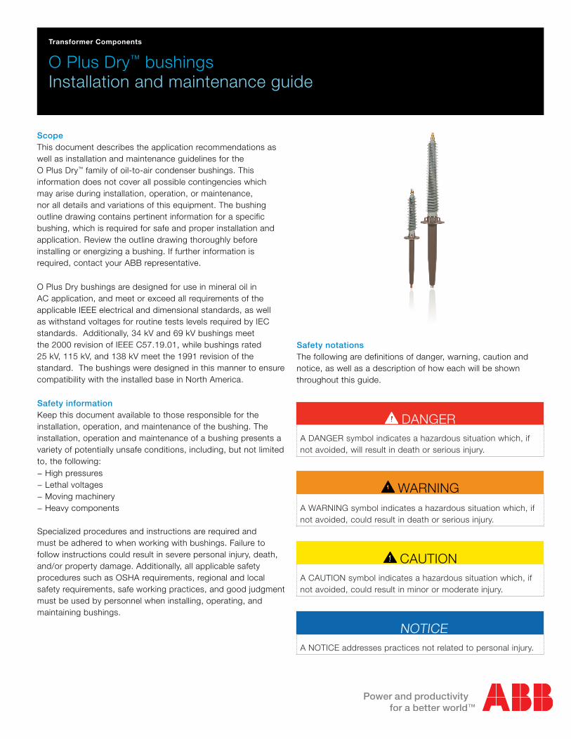
ScopeThis document describes the application recommendations as well as installation and maintenance guidelines for the O Plus Dry™ family of oil-to-air condenser bushings. This information does not cover all possible contingencies which may arise during installation, operation, or maintenance, nor all details and variations of this equipment. The bushing outline drawing contains pertinent information for a specific bushing, which is required for safe and proper installation and application. Review the outline drawing thoroughly before installing or energizing a bushing. If further information is required, contact your ABB representative.
O Plus Dry bushings are designed for use in mineral oil in AC application, and meet or exceed all requirements of the applicable IEEE electrical and dimensional standards, as well as withstand voltages for routine tests levels required by IEC standards. Additionally, 34 kV and 69 kV bushings meet the 2000 revision of IEEE C57.19.01, while bushings rated 25 kV, 115 kV, and 138 kV meet the 1991 revision of the standard. The bushings were designed in this manner to ensure compatibility with the installed base in North America.
Safety informationKeep this document available to those responsible for the installation, operation, and maintenance of the bushing. The installation, operation and maintenance of a bushing presents a variety of potentially unsafe conditions, including, but not limited to, the following:
− High pressures − Lethal voltages − Moving machinery − Heavy components
Specialized procedures and instructions are required and must be adhered to when working with bushings. Failure to follow instructions could result in severe personal injury, death, and/or property damage. Additionally, all applicable safety procedures such as OSHA requirements, regional and local safety requirements, safe working practices, and good judgment must be used by personnel when installing, operating, and maintaining bushings.
CAUTIONA CAUTION symbol indicates a hazardous situation which, if not avoided, could result in minor or moderate injury.
Safety notationsThe following are definitions of danger, warning, caution and notice, as well as a description of how each will be shown throughout this guide.
WARNINGA WARNING symbol indicates a hazardous situation which, if not avoided, could result in death or serious injury.
DANGERA DANGER symbol indicates a hazardous situation which, if not avoided, will result in death or serious injury.
NOTICEA NOTICE addresses practices not related to personal injury.

2 O Plus Dry bushings guide
Shipping methodsO Plus Dry bushings are shipped from the factory with the flange and top terminal stud supported. ABB recommends that these bushings be shipped or stored in their original packaging. If the original packaging is not available, the bushing must be supported in a way that prevents the weather sheds from being damaged. Additionally, the packaging must protect the bushing from exposure to ultra-violet light and water.
WARNING
Failure to follow these guidelines may result in damage to the bushing and cause an electrical failure. Failure to follow these guidelines will also void the warranty of the bushing.
HandlingWhen a bushing is received, examine it for any damage incurred during shipment. Inspect the surface of the epoxy lower end for scratches or cracks. Inspect the silicone weather sheds for any nicks or tears. If damage or rough handling is evident, file a claim with the transportation company and immediately notify ABB.
Before lifting the bushing, remove any banding iron, clamps or mounting flange screws holding the bushing in the packaging.
Top terminal stud
Weather sheds
Test or voltagetap
Mounting flange
Corona ring
Lifting lug
Figure 1 - O Plus Dry bushing overview
Lower end
Air-side
Oil-sideGasket surface
NOTICE
An exposed blade should not be used to remove packaging from the bushing as damage to the sheds or epoxy could occur. Additionally, to re-ship or store the bushing, some packaging will need to be re-used.
O Plus Dry bushings are significantly lighter and easier to handle than comparable oil-filled bushings. However, due to the weight and dimensions of bushings, lifting can be hazardous and should only be attempted by properly trained professionals using properly rated equipment and components. Please refer to the outline drawing to determine a bushing’s weight. Also, be mindful of the center of gravity while lifting as some bushings may rotate towards the air-side.
Bushings rated 69 kV and below have two tapped holes (0.5 – 13 UNC) in the flange that swivel hoist rings should be completely threaded into for lifting. Bushings rated above 69 kV have tapped holes as well as lifting lugs cast into the flange.

O Plus Dry bushings guide 3
CAUTION
Team-lifting should only be attempted by physically fit individuals in accordance with safe working practices, OSHA requirements, and both regional and local safety requirements.
Figure 4 - Small O Plus Dry bushing team-lift
Figure 3 - Small O Plus Dry bushing crane-lift
Figure 2 - Incorrect lifting arrangement
Lifting bushings rated 69 kV and belowCrane lifting
Team lifting
NOTICEDepending on the length of the bolt on the swivel hoist ring, it may protrude through the bottom of the flange. When this occurs during installation, the hoist rings must be removed before tightening the mounting nuts. When removing a bushing, the mounting nuts should be loosened before fully tightening the swivel hoist ring.
WARNING
Avoid contact to the weather sheds with chains or cables, as they could damage or abrade the bushing. Only textile-covered lifting slings should be used where the sling may contact the weather sheds or the epoxy body. Additionally, do not lift by or allow lifting devices to put excessive pressure on the weather sheds of O Plus Dry bushings.
Alternatively, for smaller bushings it is possible to move and install by means of a team-lift. To team-lift the bushing, place a person at each end of the bushing. The individual on the air-side can lift the bushing by the conductor, but should avoid handling the weather sheds. The individual on the oil-side can lift by the conductor and epoxy bushing body.
It is important to note that these smaller bushings have a lower center of mass, causing the bushings to naturally try to upright themselves while lifting.
For lifting bushings rated at or below 69 kV from a horizontal crate, ABB recommends using one crane hook and a person to guide the bushing using the following process.
− Remove any hardware affixing the bushing to the crate. − Completely thread the swivel hoist rings into the dedicated tapped holes (0.5 – 13 UNC) on the flange.
− Attach a sling to each of the swivel hoist rings. − Without crossing the slings, attach these slings to the crane hook.
− Slowly raise the hook while someone steadies the bushing. − Continue to raise the bushing, gradually rotating the bushing into the vertical position. Be sure that the slings do not cross or apply excessive pressure to the weather sheds.

4 O Plus Dry bushings guide
Lifting bushings rated above 69 kV
For lifting bushings rated above 69 kV from a horizontal crate, ABB recommends utilizing a lifting beam along with two cranes or a single crane and a chain hoist.
Lifting is dependent on the connection methods a bushing was designed to accommodate. However, for both convertible and bottom-connected bushings the same process can be used to secure slings to the flange.
− Remove any hardware affixing the bushing to the crate. − For vertical installation of the bushing, use swivel hoist rings threaded into the dedicated tapped holes on the flange (holes are 0.5-13UNC).
− For non-vertical installation of the bushing, the lifting lugs on the flange may be used.
− Attach a sling to each lifting lug or swivel hoist ring. − Attach the two slings to a lifting beam. − Slightly raise the crane attached to the lifting beam to lift the bushing. This will aid in attaching the devices described in the appropriate air-side connection section.
Flange connection
Air-side connection for bottom-connected bushingsUpper support for the bushing is required since the center of gravity is above the flange. For bottom-connected bushings, the top terminal stud may be used for support and the following process is recommended. Please note, this method may not be used for convertible bushings that are being bottom-connected. Instead use the lifting method for convertible bushings described in the next section.
− Affix a swivel hoist ring to the top terminal stud via the mounting hole (0.5-13UNC; 0.75 in. max length).
− Attach a sling to the swivel hoist ring and connect it to an additional crane hook. If an additional crane hook is not available, a chain hoist may be used instead.
− Raise the bushing slowly by simultaneously raising both the crane hook attached to the lifting beam and the second crane hook or chain hoist. Be sure to steady the bushing while doing so.
− Continue to raise the bushing. Gradually rotate the bushing into the vertical position by raising the crane hook or chain hoist attached to the top terminal stud. Be sure that the slings do not cross or apply excessive pressure to the weather sheds.
Figure 5 - Lifting with two crane hooks and top terminal stud support
Figure 6 - Lifting with a single crane hook and top terminal stud support

O Plus Dry bushings guide 5
Air-side connection for convertible bushings
Figure 9 - Preparing the sandwich sling
Figure 7 - Threading the air-side support sling
Figure 8 - Lifting with a single crane hook and sandwich sling support
1 - Sling, single loop 2 - 180° twist 3 - Fold in half 4 - Sling on bushing 5 - Twist sides
BushingBushing
Upper support for the bushing is required since the center of gravity is above the flange. For draw-lead connected bushings, the top terminal stud will not be present during lifting. The following process is recommended:
− Using a 3 foot sling, twist the sling once and fold in half at the cross point to make a double loop (see figure 9).
− Slide the double loop over the air-side of the bushing and stop at approximately 3 or 4 sets of weather sheds from the top.
− Position the sling such that each loop of the double loop sandwiches the smaller, inner weather shed.
− Twist each side of the sling (see figures 7 and 9). − Be sure that one of the looped sides of the sandwich sling sits between two large weather sheds.
− On the other looped side, the sling should sandwich one large weather shed and the twist should be made in the same direction as the contour of the helix. In other words the twist of the sling should not cut across the shed profile, but rather the gap in the apex of the twist should align with the shed profile leaving room for the shed.
− The sandwich sling should be as close to the bushing body as possible without putting undue stress on the weather sheds. Usually twists of 180° are sufficient but if the sandwich sling is too loose more twists can be used.
− Connect two additional slings to the flange via the lifting lugs or swivel hoist rings.
− Thread each newly connected sling through the outer loops created on the sandwich sling. Each of the loops created should be large enough so as not to restrict movement of the threaded slings (see figure 7).
− Without crossing the slings, connect the threaded slings to an additional crane hook. If an additional crane hook is not available, a chain hoist may be used instead (see figure 8).
− Raise the bushing slowly by simultaneously raising both the crane hook attached to the lifting beam and the second crane hook or chain hoist. Be sure to steady the bushing while doing so.
− Continue to raise the bushing. Gradually rotate the bushing into the vertical position by raising the crane hook or chain hoist attached to the slings threaded through the sandwich sling. Be sure that the slings do not cross or apply excessive pressure to the weather sheds.

6 O Plus Dry bushings guide
StorageO Plus Dry bushings can be stored in the original packaging in most environments for up to two years. During storage, suitable protection must be provided for terminals and mounting hardware as well as against rodents. For long term storage, the terminal contact surfaces and the gasket surface on the underside of the flange must be coated with grease. Greasing these surfaces will help prevent oxidation.
If the original packaging is not available or for long-term storage, the bushings should be stored indoors with the lower end protected from ultraviolet light, water, contamination, and rodents. It is critical that the bushing is not supported by the silicone rubber weather sheds.
InstallationPrior to installation, wipe the bushing clean of all dust or particles of packing materials using a clean dry cloth and concentrated isopropyl alcohol. Clean the inside of the conductor tube (if open at the oil end) with an isopropyl alcohol soaked swab to remove any contaminants that may have entered the tube during shipping or storage.
WARNING
The installation of a bushing involves the use of heavy equipment as well as high voltages. Do not attempt to move or install a bushing unless qualified to do so and the instructions in this document have been fully read and understood.
NOTICE
Immediately clean up any oil that may get on the weather sheds during installation. Use a clean dry rag to mop up any excess oil and then isopropyl alcohol to clean away any residual oil.
NOTICE
Many products contain isopropyl alcohol. Care must be taken to ensure that alcohol for cleaning is fragrance and dye free. Only (anhydrous) isopropyl alcohol (containing only isopropyl alcohol and water) should be used for cleaning O Plus Dry bushings.
The capacitance and power factor of O Plus Dry bushings should be measured in accordance with the sections titled Field measurements and Measurement guidelines prior to energizing.
Always allow the bushing to equalize to the temperature of the equipment on which it is being installed prior to energizing.
BoltingTighten the mounting bolts a fraction of a turn at a time, working in a crisscross or star pattern until all bolts are uniformly tight. Tighten sufficiently to seal the bushing to the equipment. Normally, the torque values listed below will provide adequate gasket compression for sealing and fastening to the equipment. Please note, that in some cases the indicated torque values may require grade 5 or higher mounting hardware.
Bolt diameter
(inches)
Threads per
inch
Torque (lbf·ft | N·m)
69 kV and below Above 69 kV
1/2 13 25 | 34 50 | 68
5/8 11 30 | 41 62 | 84
3/4 10 35 | 48 75 | 102
1 8 N/A 100 |136DANGERWhen installing bushings, be sure that all equipment is properly de-energized and grounded.
When re-shipping, O Plus Dry bushings should be secured in the original packaging (Please see the Shipping methods section). For draw-lead connected bushings, ensure that the top terminal stud is stored securely with the bushing during shipment.
Repackaging for subsequent shipment

O Plus Dry bushings guide 7
Figure 10 - Retaining pin in draw-lead stud
Top terminal stud tightnessAll bushings leave the factory with a threaded top terminal stud in place that is tightened to the proper torque. Generally, the top terminal stud on bottom-connected bushings is not removable and should not need tightened. If a loose top terminal stud is suspected on a bottom-connected bushing contact ABB for further assistance.
For draw-lead connected bushings, the top terminal stud is removable and must be torqued to 85 lbf·ft (115 N·m) for bushings rated at or below 69 kV, and 125 lbf·ft (170 N·m) for bushings rated above 69 kV. Before assembling the top terminal stud, make sure that the threads on the mating parts are clean. If not, clean the threads with a wire brush. Additionally, confirm that the O-rings are present in the top terminal stud. The contact and O-ring sealing surfaces between the top terminal stud and the conductor also need a thin film of grease (see figure 11). Then, screw the top terminal stud onto the draw-lead stud and tighten to the recommended torque.
Internal electrical connectionsThe method used to make connections between a bushing and the equipment on which it is mounted will depend on the type of connection used during the manufacture of the equipment.
Bottom-connected bushingsBushings rated 1200 amperes and higher carry the current through the center conductor. There are a variety of lower end options to coordinate with IEEE Std. C57.19.01-2001. Please refer to the specific outline drawing for details.
O Plus Dry bushings rated 115 kV and above that can be converted from either draw-lead to bottom-connected come with a corona ring attached. In order to bottom-connect these bushings, a separate shield and terminal kit must be ordered and installed. Additionally, the corona ring must first be removed by loosening the set screw and unscrewing the corona ring from the lower support of the bushing. When bottom-connected, there is no need to convert the top terminal stud.
Draw-lead connected bushingsDraw-lead bushings have a hollow conductor through which a current-carrying cable can be passed and attached to the draw-lead stud of a bushing. Please note, the cable is part of the equipment on which the bushing is being installed and is not supplied with the bushing. O Plus Dry bushings with a current rating at or below 1200 A are generally designed with this type of hollow conductor. Many of these bushings are convertible from draw-lead to bottom-connected. To determine if a particular style is convertible please refer to the outline drawing or contact your ABB representative.
To install a draw-lead connected O Plus Dry bushing, remove the top terminal stud, the retaining pin, and the draw-lead stud. The draw-lead stud must be lowered through the conductor tube to be removed. Next, pass a cable or cord through the bushing center conductor. Attach it to the hole at the top end of the draw-lead stud connected to the equipment manufacturer’s flexible cable. Lower the bushing into the mounting hole while simultaneously pulling the cable up through the center conductor of the bushing. Secure the draw-lead connected stud to the draw-lead adapter by inserting the retaining pin. The top terminal stud will need to be installed next. Refer to the section titled Top terminal stud tightness for assembly and tightening of the top terminal stud.
Figure 11 - Draw-lead lubrication points
NOTICE
Only clean grease with a composition that is free of metal and sulfur should be used on bushings.
O-rings
Contact surface
O-ring sealing surface

E
B
A
C
D
8 O Plus Dry bushings guide
Draw-lead studThe draw-lead stud (see figure 14) is a crimp-type design similar to other studs used throughout the industry for many years. Reference dimensions of the stud furnished with the bushing are included in the table below. Replacement, as well as crimp-type studs with other dimensions, are available for purchase.
Rated 69 kV and
below
Above 69 kV
A (in | mm) 0.70 | 17.8 1.15 | 29.3
B (in | mm) 1.63 | 41.5 1.65 | 42.0
C (in | mm) 1.22 | 31.0 1.77 | 45.0
D (in | mm) 4.41 | 112 .0 5.00 | 127.0
E (in | mm) 0.20 | 5.2 0.20 | 5.2
WARNING
Before applying vacuum to a transformer, be certain there is sufficient slack in the line connections to the bushing allowing for bushing movement caused by flexing of the transformer cover and/or walls. Failure to relieve this stress at the bushing connection may break the bushing body.
Internal and external electrical connectionsThe connections to the bushing must be either sufficiently supported or flexible enough to avoid putting an excessive mechanical strain on the bushing. Allowable cantilever loads are presented in the table below:
Tap connectionsO Plus Dry bushings have a small housing containing either a test tap or voltage tap as part of the mounting flange. Bushings rated 69 kV and below have a test tap while bushings with a rating greater than 69 kV have a voltage tap (see figures 12 and 13). Both taps provide a convenient means for making power factor and capacitance measurements by the ungrounded specimen test (UST) method.
In order to connect to the test tap on bushings rated 69 kV and below, remove the threaded cover and connect the UST lead of the power factor measuring equipment to the terminal spring. After testing has been completed, replacing the test tap cover will ground the test tap for service operation of the bushing. Tighten the tap cover to a torque of 10 lbf·ft (13.6 N·m).
CAUTION
Do not apply voltage to the bushing with the test or voltage tap cover removed, except when measuring power factor. If the tap connection is not grounded, the tap voltage will exceed the insulation dielectric strength, resulting in a flashover. The voltage on a voltage tap must not exceed 2 kV when measuring power factor. The voltage on the test tap must be limited to 1 kV for reverse UST tests.
Figure 14 - Draw-lead stud
External terminal connectors, eg NEMA terminals, should be selected of the appropriate size and material to keep the connectors below 70 °C at rated current. Additional conditions, such as overloads, should be considered during the selection of the terminal connector. This will minimize the risk of overheating and possible damage to the bushing.
Voltage
rating
(kV)
Current
rating
(A)
Top terminal stud Lower terminal
Continuous
(lbf | N)
Short-term
(lbf | N)
Continuous
(lbf | N)
Short-term
(lbf | N)
25 1200 150 | 667 255 | 1134 100 | 445 170 | 756
2000 225 | 1000 382 | 1700 100 | 445 170 | 756
3000 354 | 1575 601 | 2677 150 | 667 255 | 1134
34 1200 150 | 667 255 | 1134 100 | 445 170 | 756
2000 225 | 1000 382 | 1700 100 | 445 170 | 756
3000 354 | 1575 601 | 2677 150 | 667 255 | 1134
69 1200 150 | 667 255 | 1134 100 | 445 170 | 756
2000 225 | 1000 382 | 1700 100 | 445 170 | 756
3000 450 | 2000 764 | 3399 150 | 667 255 | 1134
115 1200 354 | 1575 602 | 2678 350 | 1557 595 | 2647
2000 350 | 1557 595 | 2647 350 | 1557 595 | 2647
3000 450 | 2000 765 | 3400 350 | 1557 595 | 2647
138 1200 354 | 1575 602 | 2676 350 | 1557 595 | 2647
2000 350 | 1557 595 | 2647 350 | 1557 595 | 2647
3000 450 | 2000 765 | 3400 350 | 1557 595 | 2647
Figure 12 - Test tap Figure 13 - Voltage tap
A
5
A B B B C
10 15 20 25 30Years
Service level
O Plus Dry bushings guide 9
Bushings with a voltage tap, rated above 69 kV, can also be tested as previously described. After testing has been completed, replacing the tap cover will ground the voltage tap for service operation by means of a spring clip in the cover. A layer of grease should be applied to the sealing gasket. Tighten the tap cover to a torque of 15 lbf·ft (20 N·m).
The voltage tap on bushings rated above 69 kV may also be used for monitoring purposes. Because of the typically low operating voltage of monitoring equipment, it is not necessary to add any insulating filler to the voltage tap for this application.
Additionally, a bushing potential device may be connected to a voltage tap. If applying a bushing potential device, the voltage tap must be filled with transformer oil prior to energizing. To do this, remove the fill plug and fill the chamber with clean, dry transformer oil. To avoid overfilling the chamber, leave an expansion space of approximately 1/4 inch (6 mm) air space at the top of the chamber. Finally, replace the plug and ensure that the plug is tightened to 40 lbf·in (4.5 N·m).
WARNING
Do not remove the voltage tap fill plug when the bushing is at an elevated temperature, because the oil inside the bushing may be very hot and under high pressure. Make sure the bushing temperature is in the 15 °C to 35 °C range. Failure to follow these guidelines could result in severe personal injury.
Nameplate dataNameplate data is of special importance in answering questions about bushings. All requests will be expedited if the factory is furnished with the serial number, the functional style number, version number, and the year of manufacture as indicated on the bushing nameplate. At a minimum, the factory should be provided with the serial number of the bushing in question.
Cleaning of the weather shedsMost O Plus Dry bushings will be self-cleaning and will not require cleaning throughout their lifetime. Occasionally the surface may appear dirty, but in most cases this will not affect the bushing performance. However, if taking a transformer out of service, cleaning the weather sheds can be done as preventive maintenance.
Bushings exposed to salt spray, cement dust, coal dust or other abnormal deposits are subject to special contamination related hazards and may occasionally need cleaned to prevent flashover and corrosion of parts. ABB recommends extra heavy creep for these types of environments.
A clean silicone weather shed is hydrophobic in nature. This property can be noted by the beading of water droplets. Sheds are adequately clean when less than 90 percent of the surface exhibits water runs or film. It is ABB’s recommendation to schedule cleaning should 50 percent of the shed surface present conditions of water runs or film. Any shed exhibiting runs or film over 90 percent of its surface should be cleaned immediately. For more information on how to determine if an insulator meets these conditions, please refer to IEC standard 62073.
The sheds should be cleaned using a lint-free cotton cloth and isopropyl alcohol.
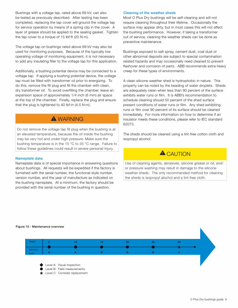
Figure 15 - Maintenance overview
Level A: Visual inspectionLevel B: Field measurementsLevel C: Consider replacement
CAUTION
Use of cleaning agents, abrasives, silicone grease or oil, and/or pressure washing may result in damage to the silicone weather sheds. The only recommended method for cleaning the sheds is isopropyl alochol and a lint-free cloth.

10 O Plus Dry bushings guide
Measurement guidelinesThough not required on O Plus Dry bushings, trend analysis of the power factor and capacitance can readily show a bushing that is deteriorating in service and should be considered for replacement. If annual measurements are not available, these guidelines provide a means for determining if a bushing has deteriorated to the point where it should be considered for replacement.
For all O Plus Dry bushings, the C1 capacitance is always controlled by the bushing’s construction and is not significantly influenced by installed conditions. The C2 capacitance in bushings rated 69 kV and below is not well controlled by the nature of its construction. Field measurements will be influenced by the proximity of other objects and the environmental conditions at or near the bushing. The C2 capacitance in bushings rated above 69 kV is controlled by its construction and is not significantly influenced by environmental conditions.
For bushings rated at or below 69 kV, consider replacement if: − The measured C1 capacitance differs by 10 percent from the nameplate value
− The measured C1 power factor is 2-times the nameplate value
Because the C2 capacitance in bushings rated 69 kV and below is not a controlled capacitance, field measurements should be compared to the installed reference value. The reference value is established when the bushing is first installed on the transformer by measuring both the C2 capacitance and power factor. Consider bushing replacement if:
− The measured C2 capacitance differs by 10 percent from the reference value
− The measured C2 power factor is 2-times the reference value
For bushings rated above 69 kV, the C2 capacitance is controlled by the nature of its construction. As such, measured values when compared to nameplate values provide an accurate assessment of a bushing’s condition. Consider replacement if:
− The measured C1 or C2 capacitance differs by 10 percent from the nameplate value
− The measured C1 or C2 power factor is 2-times the nameplate value
Field measurementsMeasure and record the power factor and capacitance at the time of installation. Field measurements of power factor and capacitance can differ from measurements made under the controlled conditions in the factory. Therefore, the power factor and capacitance measured at the time of installation should be used as a baseline to compare with future measurements as indicated in the section titled Measurement guidelines.
Use the following guidelines to minimize the effect of contamination and high humidity during power factor and capacitance measurements in the field:
− Clean the bushing thoroughly with isopropyl alcohol to remove any contaminants that may have deposited on the bushing during shipping or storage.
− After cleaning, wipe the surface dry to avoid moisture condensation.
− Clean and dry the voltage or test tap insulator to remove any contamination or condensation.
− Avoid taking power factor measurements in wooden crates to minimize the effect of surface leakage due to moist wood.
− Avoid taking measurements below 10 °C. − Provide sufficient clearance between the bushing and other objects to minimize the effects of stray capacitance.
If you obtain unsatisfactory readings, repeat the cleaning process and re-measure. If the measurement improves but is still not in the satisfactory range, clean and measure again. Repeat this process as long as the measured values keep improving.
For information on ground connections and other guidelines, please refer to the test equipment manufacturer‘s instruction manual.
MaintenanceO Plus Dry bushings require no maintenance aside from visual inspection for the first 15 years of service. In year 15 and every 5th year afterwards, field measurements should be recorded and analyzed. If operating O Plus Dry bushings in a harsh environment, more frequent testing maybe warranted. The following sections should be considered at a minimum when planning for testing and maintenance.

O Plus Dry bushings guide 11
Field repairsO Plus Dry bushings are robust in nature and likely will never need service. Repairs that can be performed on O Plus Dry bushings in the field are limited. However, if the weather shed has a small, simple tear of 0.5 inches (12.7 mm) or less it can be repaired with room temperature vulcanizing (RTV) rubber. To perform the repair, clean the two surfaces with concentrated isopropyl alcohol. Apply the RTV rubber to the two surfaces to be bonded, minimizing any overrun. Allow the repair to dry.
For all other issues, please contact ABB.
Top terminal connector inspectionFor satisfactory operation of a bushing, it is important that the top terminal connector is tight at all times. If any of the parts are loose, overheating of the current-carrying joint can take place and result in damaged terminal joints.
The preferred method for inspection is to perform an infrared scan of the top terminal connector. Another method of inspection is to observe the bushing for discoloration of the top terminal stud, external terminal connector, and bolts. Additionally, the casual observer can look for steam rising from the terminal during rain. Any of these conditions could be signs of a loose terminal or connection and require a more rigorous examination.
Inspect the terminal for signs of overheating and check the power factor and capacitance (see the sections titled Field measurements and Measurement guidelines). If any signs of overheating are present, take the bushing out of service. If the top end parts are discolored and the bushing has been installed using the draw-lead method, remove the top terminal stud and examine for any damage. If the top terminal stud cannot be removed, it has most likely suffered overheating damage.
For specific recommendations, please contact ABB.
Field correction of measurementsAs O Plus Dry bushings are new to the industry, the test equipment used for power factor and capacitance measurements may not have preset temperature correction factors. If this is the case, use the following information and equations to manually adjust for temperature corrections:
The first step is to calculate the bushing body temperature. First, measure the transformer oil temperature and the air temperature. Then, use the following equation to determine the O Plus Dry bushing temperature (Tbody):
0.6
0.7
0.8
0.9
1
1.1
1.2
1.3
1.4
1.5
0 10 20 30 40 50 60 70 80 90
Tbody (C°)
Pow
er f
acto
r co
rrec
tion
ƒ c
0 10 20 30 40 50 60 70 80 900.6
0.7
0.8
0.9
1.0
1.1
1.2
1.3
1.4
1.5
Power factor correction for O Plus Dry bushings
Based on the O Plus Dry bushing temperature calculated above, identify the corresponding power factor correction value (ƒc) in the following table.
The next step is to calculate the corrected power factor. To do this, measure the power factor in accordance with the sections titled Field measurements and Measurement guidelines. With both the correction factor and the measured power factor (PFmeasured) now determined, the corrected power factor (PF20 °C) can be calculated. The corrected power factor is representative of what the measured power factor would be if tested under controlled conditions at the factory. For more information on factory testing conditions, please refer to IEEE C57.19.00-2004.
With the temperature difference determined, the next step is to calculate the corrected C1 capacitance. To do this, measure the capacitance in accordance with the sections titled Field measurements and Measurement guidelines. Then use the measured C1 capacitance in the following formula:����� =
2���� + ����3
����°� = ����������
��
∆� = �����[℃] − 20℃
�1��� = �1��������
1 + 0.0003∆�
PF correction
(ƒc)
Tbody [°C]
1.430
1.1910
1.0020
0.8430
0.7540
0.7050
0.6960
0.7270
0.7880
0.9290
To correct the capacitance, the difference between the actual temperature of the bushing (Tbody) and the temperature of the bushing when tested at the factory must first be calculated.

1ZU
A27
51-2
61,
rev.
1ABB Inc.1133 South Cavalier DriveAlamo, Tennessee 38001, USAPhone: +1 800 955 8399 +1 731 696 5561Fax: +1 731 696 5377
www.abb.com/electricalcomponents
Contact us
Note:
The information contained in this document is for general information purposes only. While ABB strives to keep the information up to date and correct, it makes no representations or warranties of any kind, express or implied, about the completeness, accuracy, reliability, suitability or availability with respect to the information, products, services, or related graphics contained in the document for any purpose. Any reliance placed on such information is therefore strictly at your own risk. ABB reserves the right to discontinue any product or service at any time.
© Copyright 2015 ABB. All rights reserved.