dry system technical manual for operation, maintenance...
TRANSCRIPT
Dry System
Technical Manual for Operation, Maintenance and Troubleshooting
February, 2010 Form No. F_010608
Page II
TECHNICAL DATA
The Viking Corporation, 210 N Industrial Park Drive, Hastings MI 49058Telephone: 269-945-9501 Technical Services: 877-384-5464 Fax: 269-818-1680 Email: [email protected]
February 12, 2010
DRY PIPE SPRINkLER SYSTEM
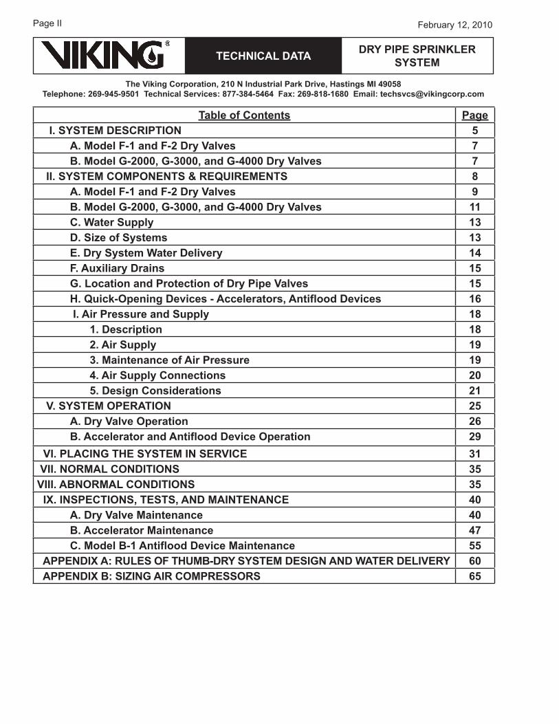
Table of Contents Page I. SYSTEM DESCRIPTION 5
A. Model F-1 and F-2 Dry Valves 7B. Model G-2000, G-3000, and G-4000 Dry Valves 7
II. SYSTEM COMPONENTS & REquIREMENTS 8A. Model F-1 and F-2 Dry Valves 9B. Model G-2000, G-3000, and G-4000 Dry Valves 11C. Water Supply 13D. Size of Systems 13E. Dry System Water Delivery 14F. Auxiliary Drains 15G. Location and Protection of Dry Pipe Valves 15H. quick-Opening Devices - Accelerators, Antiflood Devices 16 I. Air Pressure and Supply 18
1. Description 182. Air Supply 193. Maintenance of Air Pressure 194. Air Supply Connections 205. Design Considerations 21
V. SYSTEM OPERATION 25A. Dry Valve Operation 26B. Accelerator and Antiflood Device Operation 29
VI. PLACING THE SYSTEM IN SERVICE 31 VII. NORMAL CONDITIONS 35VIII. ABNORMAL CONDITIONS 35 Ix. INSPECTIONS, TESTS, AND MAINTENANCE 40
A. Dry Valve Maintenance 40B. Accelerator Maintenance 47C. Model B-1 Antiflood Device Maintenance 55
APPENDIx A: RuLES OF THuMB-DRY SYSTEM DESIGN AND WATER DELIVERY 60 APPENDIx B: SIzING AIR COMPRESSORS 65
TECHNICAL DATA
The Viking Corporation, 210 N Industrial Park Drive, Hastings MI 49058Telephone: 269-945-9501 Technical Services: 877-384-5464 Fax: 269-818-1680 Email: [email protected]
DRY PIPE SPRINkLER SYSTEM
Page �February 12, 2010
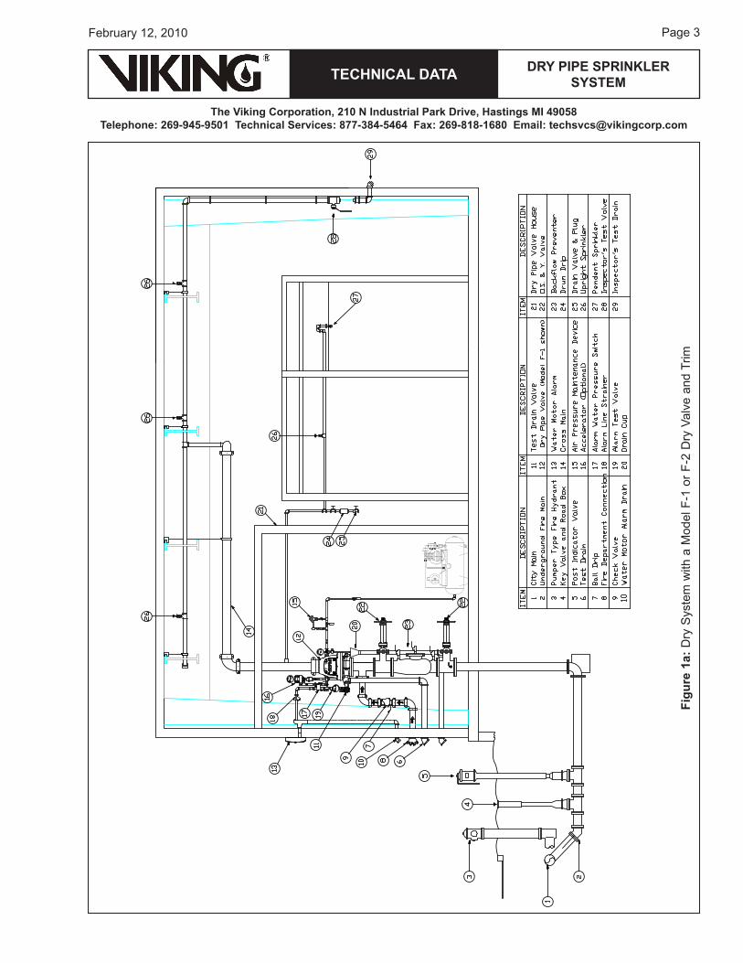
Figu
re 1
a: D
ry S
yste
m w
ith a
Mod
el F
-1 o
r F-2
Dry
Val
ve a
nd T
rim
Page �
TECHNICAL DATA
The Viking Corporation, 210 N Industrial Park Drive, Hastings MI 49058Telephone: 269-945-9501 Technical Services: 877-384-5464 Fax: 269-818-1680 Email: [email protected]
February 12, 2010
DRY PIPE SPRINkLER SYSTEM
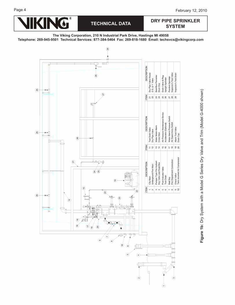
Figu
re 1
b: D
ry S
yste
m w
ith a
Mod
el G
Ser
ies
Dry
Val
ve a
nd T
rim (M
odel
G-�
000
show
n)
TECHNICAL DATA
The Viking Corporation, 210 N Industrial Park Drive, Hastings MI 49058Telephone: 269-945-9501 Technical Services: 877-384-5464 Fax: 269-818-1680 Email: [email protected]
DRY PIPE SPRINkLER SYSTEM
Page �February 12, 2010
I. SYSTEM DESCRIPTIONThe Dry Pipe Sprinkler System is a fire-protection system that utilizes water as an extinguishing agent, while the system piping from the Dry Pipe Valve to the automatic fusible sprinklers is filled with pressurized air or nitrogen. Dry pipe systems should be installed only where heat is not adequate to prevent freezing of water in all parts of, or in sections of, the system. Air pressure must be lost from the system to trip the valve. Then water must travel through the piping network to the sprinklers (refer to Figures 1a and 1b).
Dry pipe systems require frequent inspections, testing, and maintenance in accordance with NFPA 2�. The following must be considered:
• System air pressure• Low point drainage• Dry pipe valve operation• Accelerator operation• Valve room temperature
NOTE: SPrINkLer SySTeMS Are eNGINeereD To MeeT The STANDArDS oF NFPA 1�, FM GLobAL, LoSS PreVeNTIoN CouNCIL (FoC), ASSeMbLee PLeNIere, VerbAND Der SAChVerSICher-er (VDS) or oTher SIMILAr orGANIzATIoNS, AND wILL ALSo NeeD To CoMPLy wITh The ProVISIoNS oF GoVerNMeNTAL CoDeS, orDINANCeS, AND STANDArDS where APPLICAbLe. The SySTeM MuST be DeSIGNeD by quALIFIeD DeSIGN ProFeSSIoNALS IN CoNjuNCTIoN wITh INSurING boDIeS. The uSer IS reSPoNSIbLe For The DeSIGN AND CoNFIGurATIoN oF The SySTeM, ITS APProPrIATeNeSS For The uSe INTeNDeD AND ITS CoMPLIANCe wITh ALL STANDArDS, CoDeS AND orDINANCeS. VIkING CorPorATIoN DoeS NoT DeSIGN SySTeMS For SPeCIFIC INSTALLATIoNS AND MAkeS No rePreSeNTATIoN or wArrANTy CoNCerNING wheTher ANy SPeCIFIC SySTeM INSTALLATIoN wILL be SuFFICIeNT For The INTeNDeD uSe or wILL CoMPLy wITh ANy STANDArD, CoDe, or orDINANCe. ANy SySTeM DePICTeD IN ThIS MANuAL IS ShowN For ILLuSTrATIVe PurPoSeS oNLy.
Figure 2
Page 6
TECHNICAL DATA
The Viking Corporation, 210 N Industrial Park Drive, Hastings MI 49058Telephone: 269-945-9501 Technical Services: 877-384-5464 Fax: 269-818-1680 Email: [email protected]
February 12, 2010
DRY PIPE SPRINkLER SYSTEM
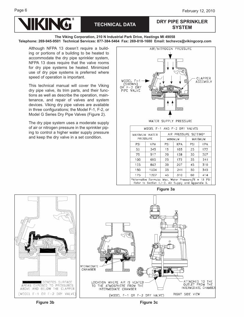
Although NFPA 1� doesn’t require a build-ing or portions of a building to be heated to accommodate the dry pipe sprinkler system, NFPA 1� does require that the valve rooms for dry pipe systems be heated. Minimized use of dry pipe systems is preferred where speed of operation is important.
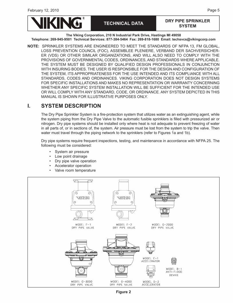
This technical manual will cover the Viking dry pipe valve, its trim parts, and their func-tions as well as describe the operation, main-tenance, and repair of valves and system devices. Viking dry pipe valves are available in three configurations; the Model F-1, F-2, or Model G Series Dry Pipe Valves (Figure 2).
The dry pipe system uses a moderate supply of air or nitrogen pressure in the sprinkler pip-ing to control a higher water supply pressure and keep the dry valve in a set condition.
Figure 3a
Figure 3cFigure 3b
TECHNICAL DATA
The Viking Corporation, 210 N Industrial Park Drive, Hastings MI 49058Telephone: 269-945-9501 Technical Services: 877-384-5464 Fax: 269-818-1680 Email: [email protected]
DRY PIPE SPRINkLER SYSTEM
Page �February 12, 2010
A. Model F-1 and F-2 Dry Valvesrated to 1�� PSI (12.1 bar) water working Pressure
A lower air pressure is able to keep the valve closed against the higher water pressure due to a dif-ference in the surface area of the clapper, on which the respective pressures are applied (Figure �a). The differential is created through the clapper assembly of the dry valve itself. The clapper is latched, creating a positive mechanical seal.
The area exposed to pressure above the clapper is considerably larger than the area exposed to pressure below the clapper when the clapper is in the set position (Figure �b). The area in between, the intermediate chamber (see Figure �c), is vented to atmosphere. It’s important that air is constantly vented to the atmosphere because any pressure buildup in the intermediate chamber will act to over-come the differential (Figure �c).
CAuTION: Do not perform hydrostatic test with the dry valve closed!
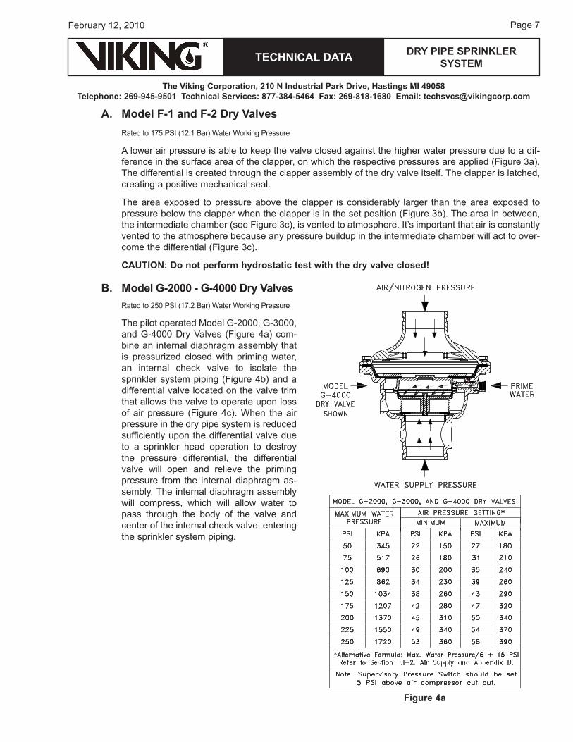
B. Model G-2000 - G-4000 Dry Valvesrated to 2�0 PSI (1�.2 bar) water working Pressure
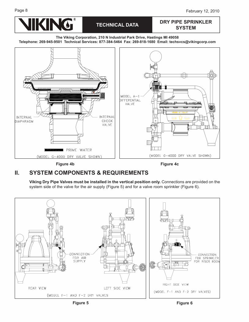
The pilot operated Model G-2000, G-�000, and G-�000 Dry Valves (Figure �a) com-bine an internal diaphragm assembly that is pressurized closed with priming water, an internal check valve to isolate the sprinkler system piping (Figure �b) and a differential valve located on the valve trim that allows the valve to operate upon loss of air pressure (Figure �c). when the air pressure in the dry pipe system is reduced sufficiently upon the differential valve due to a sprinkler head operation to destroy the pressure differential, the differential valve will open and relieve the priming pressure from the internal diaphragm as-sembly. The internal diaphragm assembly will compress, which will allow water to pass through the body of the valve and center of the internal check valve, entering the sprinkler system piping.
Figure 4a
Page 8
TECHNICAL DATA
The Viking Corporation, 210 N Industrial Park Drive, Hastings MI 49058Telephone: 269-945-9501 Technical Services: 877-384-5464 Fax: 269-818-1680 Email: [email protected]
February 12, 2010
DRY PIPE SPRINkLER SYSTEM
II. SYSTEM COMPONENTS & REquIREMENTSViking Dry Pipe Valves must be installed in the vertical position only. Connections are provided on the system side of the valve for the air supply (Figure �) and for a valve room sprinkler (Figure 6).
Figure 4b
Figure 5 Figure 6
Figure 4c
TECHNICAL DATA
The Viking Corporation, 210 N Industrial Park Drive, Hastings MI 49058Telephone: 269-945-9501 Technical Services: 877-384-5464 Fax: 269-818-1680 Email: [email protected]
DRY PIPE SPRINkLER SYSTEM
Page �February 12, 2010
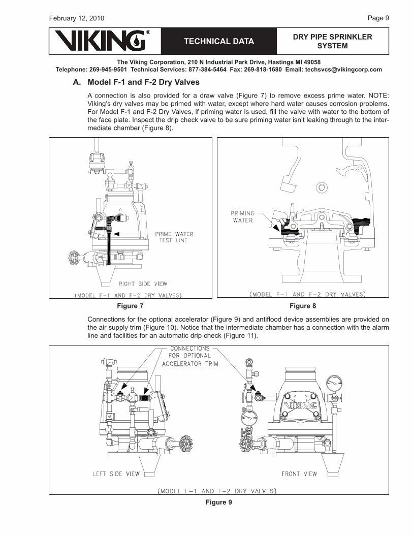
A. Model F-1 and F-2 Dry ValvesA connection is also provided for a draw valve (Figure �) to remove excess prime water. NoTe: Viking’s dry valves may be primed with water, except where hard water causes corrosion problems. For Model F-1 and F-2 Dry Valves, if priming water is used, fill the valve with water to the bottom of the face plate. Inspect the drip check valve to be sure priming water isn’t leaking through to the inter-mediate chamber (Figure 8).
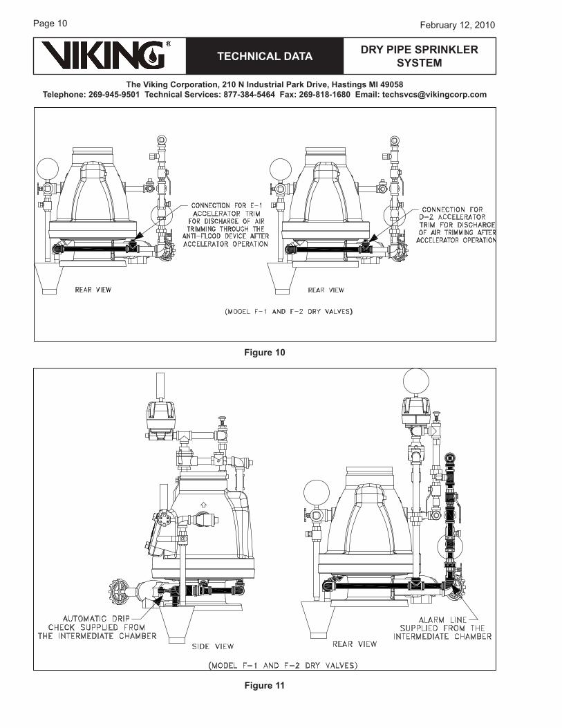
Connections for the optional accelerator (Figure �) and antiflood device assemblies are provided on the air supply trim (Figure 10). Notice that the intermediate chamber has a connection with the alarm line and facilities for an automatic drip check (Figure 11).
Figure 7 Figure 8
Figure 9
Page 10
TECHNICAL DATA
The Viking Corporation, 210 N Industrial Park Drive, Hastings MI 49058Telephone: 269-945-9501 Technical Services: 877-384-5464 Fax: 269-818-1680 Email: [email protected]
February 12, 2010
DRY PIPE SPRINkLER SYSTEM
Figure 10
Figure 11
TECHNICAL DATA
The Viking Corporation, 210 N Industrial Park Drive, Hastings MI 49058Telephone: 269-945-9501 Technical Services: 877-384-5464 Fax: 269-818-1680 Email: [email protected]
DRY PIPE SPRINkLER SYSTEM
Page 11February 12, 2010
The automatic drip feature plays an important role by allowing small amounts of water or air to escape past the clapper and to remove it from the valve without developing pressure in the intermediate chamber by depressing the plunger. Such pressure would disrupt the valve differential ratio, which might cause the valve to trip. There is also a connection between the intermediate chamber and the optional accelerator and the antiflood device.
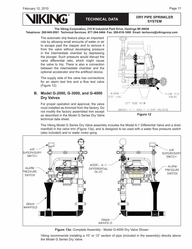
The supply side of the valve has connections for an alarm test line and a flow test valve (Figure 12).
B. Model G-2000, G-3000, and G-4000 Dry ValvesFor proper operation and approval, the valve must installed as trimmed from the factory. Do not modify the factory assembled trim except as described in the Model G Series Dry Valve technical data sheet.
The Viking Model G Series Dry Valve assembly includes the Model A-1 Differential Valve and a drain manifold in the valve trim (Figure 1�a), and is designed to be used with a water flow pressure switch (also included) and or water motor gong.
Viking recommends installing a 10” or 12” section of pipe (included in the assembly) directly above the Model G Series Dry Valve.
Figure 12
Figure 13a: Complete Assembly - Model G-�000 Dry Valve Shown
Page 12
TECHNICAL DATA
The Viking Corporation, 210 N Industrial Park Drive, Hastings MI 49058Telephone: 269-945-9501 Technical Services: 877-384-5464 Fax: 269-818-1680 Email: [email protected]
February 12, 2010
DRY PIPE SPRINkLER SYSTEM
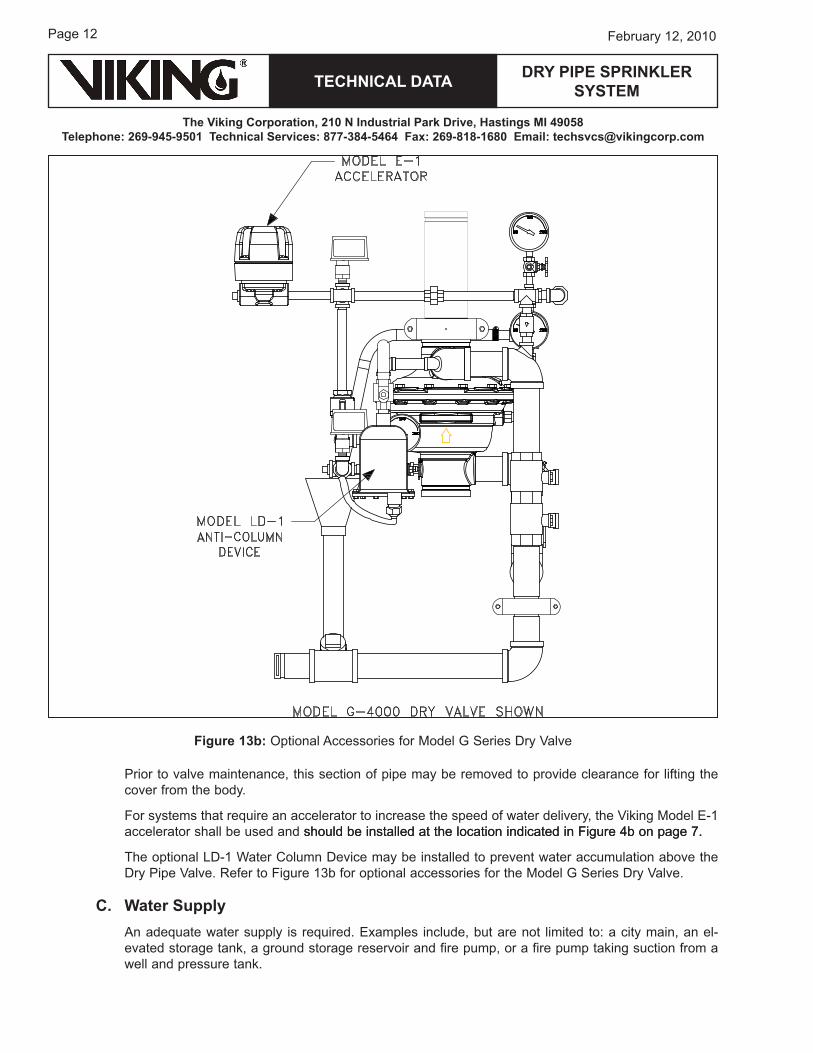
Prior to valve maintenance, this section of pipe may be removed to provide clearance for lifting the cover from the body.
For systems that require an accelerator to increase the speed of water delivery, the Viking Model e-1 accelerator shall be used and should be installed at the location indicated in Figure �b on page �.should be installed at the location indicated in Figure �b on page �..
The optional LD-1 water Column Device may be installed to prevent water accumulation above the Dry Pipe Valve. refer to Figure 1�b for optional accessories for the Model G Series Dry Valve.
C. Water SupplyAn adequate water supply is required. examples include, but are not limited to: a city main, an el-evated storage tank, a ground storage reservoir and fire pump, or a fire pump taking suction from a well and pressure tank.
Figure 13b: optional Accessories for Model G Series Dry Valve
TECHNICAL DATA
The Viking Corporation, 210 N Industrial Park Drive, Hastings MI 49058Telephone: 269-945-9501 Technical Services: 877-384-5464 Fax: 269-818-1680 Email: [email protected]
DRY PIPE SPRINkLER SYSTEM
Page 1�February 12, 2010
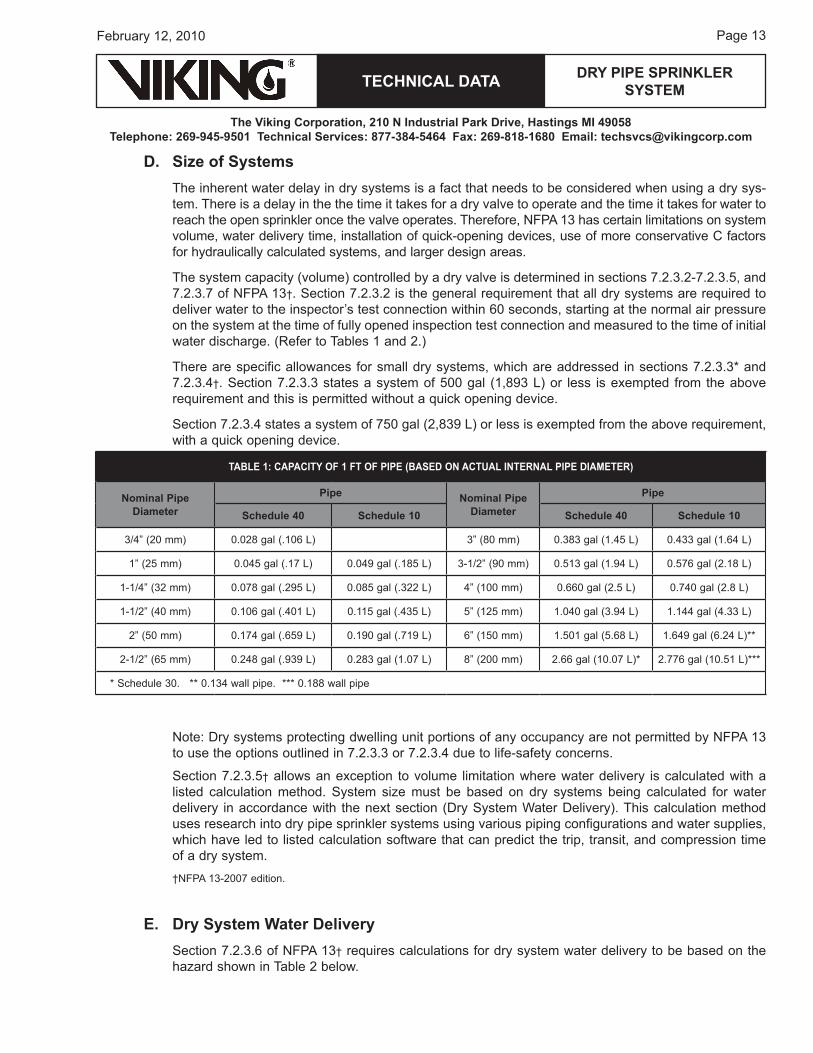
D. Size of SystemsThe inherent water delay in dry systems is a fact that needs to be considered when using a dry sys-tem. There is a delay in the the time it takes for a dry valve to operate and the time it takes for water to reach the open sprinkler once the valve operates. Therefore, NFPA 1� has certain limitations on system volume, water delivery time, installation of quick-opening devices, use of more conservative C factors for hydraulically calculated systems, and larger design areas.
The system capacity (volume) controlled by a dry valve is determined in sections �.2.�.2-�.2.�.�, and �.2.�.� of NFPA 1�†. Section �.2.�.2 is the general requirement that all dry systems are required to deliver water to the inspector’s test connection within 60 seconds, starting at the normal air pressure on the system at the time of fully opened inspection test connection and measured to the time of initial water discharge. (refer to Tables 1 and 2.)
There are specific allowances for small dry systems, which are addressed in sections �.2.�.�* and �.2.�.�†. Section �.2.�.� states a system of �00 gal (1,8�� L) or less is exempted from the above requirement and this is permitted without a quick opening device.
Section �.2.�.� states a system of ��0 gal (2,8�� L) or less is exempted from the above requirement, with a quick opening device.
Note: Dry systems protecting dwelling unit portions of any occupancy are not permitted by NFPA 1� to use the options outlined in �.2.�.� or �.2.�.� due to life-safety concerns.
Section �.2.�.�† allows an exception to volume limitation where water delivery is calculated with a listed calculation method. System size must be based on dry systems being calculated for water delivery in accordance with the next section (Dry System water Delivery). This calculation method uses research into dry pipe sprinkler systems using various piping configurations and water supplies, which have led to listed calculation software that can predict the trip, transit, and compression time of a dry system. †NFPA 1�-200� edition.
E. Dry System Water DeliverySection �.2.�.6 of NFPA 1�† requires calculations for dry system water delivery to be based on the hazard shown in Table 2 below.
TABLE 1: CAPACITY OF 1 FT OF PIPE (BASED ON ACTuAL INTERNAL PIPE DIAMETER)
Nominal Pipe Diameter
Pipe Nominal Pipe Diameter
Pipe
Schedule 40 Schedule 10 Schedule 40 Schedule 10
�/�” (20 mm) 0.028 gal (.106 L) �” (80 mm) 0.�8� gal (1.�� L) 0.��� gal (1.6� L)
1” (2� mm) 0.0�� gal (.1� L) 0.0�� gal (.18� L) �-1/2” (�0 mm) 0.�1� gal (1.�� L) 0.��6 gal (2.18 L)
1-1/�” (�2 mm) 0.0�8 gal (.2�� L) 0.08� gal (.�22 L) �” (100 mm) 0.660 gal (2.� L) 0.��0 gal (2.8 L)
1-1/2” (�0 mm) 0.106 gal (.�01 L) 0.11� gal (.��� L) �” (12� mm) 1.0�0 gal (�.�� L) 1.1�� gal (�.�� L)
2” (�0 mm) 0.1�� gal (.6�� L) 0.1�0 gal (.�1� L) 6” (1�0 mm) 1.�01 gal (�.68 L) 1.6�� gal (6.2� L)**
2-1/2” (6� mm) 0.2�8 gal (.��� L) 0.28� gal (1.0� L) 8” (200 mm) 2.66 gal (10.0� L)* 2.��6 gal (10.�1 L)***
* Schedule �0. ** 0.1�� wall pipe. *** 0.188 wall pipe
Page 1�
TECHNICAL DATA
The Viking Corporation, 210 N Industrial Park Drive, Hastings MI 49058Telephone: 269-945-9501 Technical Services: 877-384-5464 Fax: 269-818-1680 Email: [email protected]
February 12, 2010
DRY PIPE SPRINkLER SYSTEM
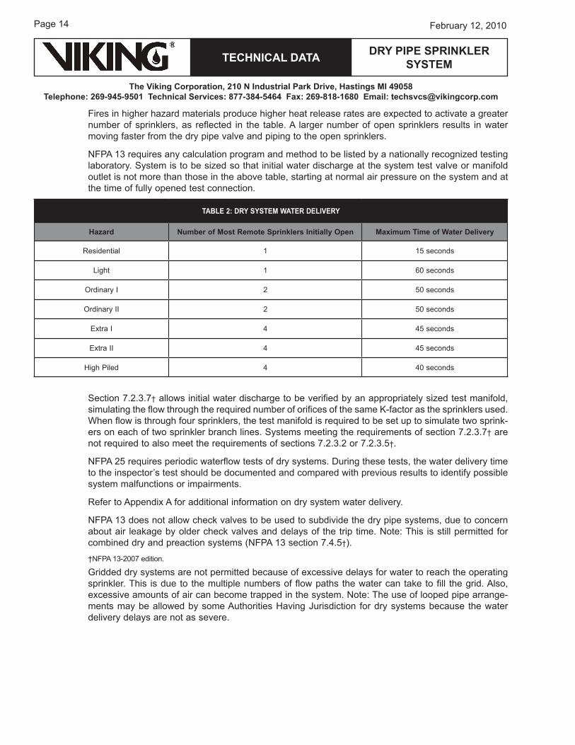
Fires in higher hazard materials produce higher heat release rates are expected to activate a greater number of sprinklers, as reflected in the table. A larger number of open sprinklers results in water moving faster from the dry pipe valve and piping to the open sprinklers.
NFPA 1� requires any calculation program and method to be listed by a nationally recognized testing laboratory. System is to be sized so that initial water discharge at the system test valve or manifold outlet is not more than those in the above table, starting at normal air pressure on the system and at the time of fully opened test connection.
Section �.2.�.�† allows initial water discharge to be verified by an appropriately sized test manifold, simulating the flow through the required number of orifices of the same k-factor as the sprinklers used. when flow is through four sprinklers, the test manifold is required to be set up to simulate two sprink-ers on each of two sprinkler branch lines. Systems meeting the requirements of section �.2.�.�† are not required to also meet the requirements of sections �.2.�.2 or �.2.�.�†.
NFPA 2� requires periodic waterflow tests of dry systems. During these tests, the water delivery time to the inspector’s test should be documented and compared with previous results to identify possible system malfunctions or impairments.
refer to Appendix A for additional information on dry system water delivery.
NFPA 1� does not allow check valves to be used to subdivide the dry pipe systems, due to concern about air leakage by older check valves and delays of the trip time. Note: This is still permitted for combined dry and preaction systems (NFPA 1� section �.�.�†).†NFPA 1�-200� edition.
Gridded dry systems are not permitted because of excessive delays for water to reach the operating sprinkler. This is due to the multiple numbers of flow paths the water can take to fill the grid. Also, excessive amounts of air can become trapped in the system. Note: The use of looped pipe arrange-ments may be allowed by some Authorities having jurisdiction for dry systems because the water delivery delays are not as severe.
TABLE 2: DRY SYSTEM WATER DELIVERY
Hazard Number of Most Remote Sprinklers Initially Open Maximum Time of Water Delivery
residential 1 1� seconds
Light 1 60 seconds
ordinary I 2 �0 seconds
ordinary II 2 �0 seconds
extra I � �� seconds
extra II � �� seconds
high Piled � �0 seconds
TECHNICAL DATA
The Viking Corporation, 210 N Industrial Park Drive, Hastings MI 49058Telephone: 269-945-9501 Technical Services: 877-384-5464 Fax: 269-818-1680 Email: [email protected]
DRY PIPE SPRINkLER SYSTEM
Page 1�February 12, 2010
F. Auxiliary Drains Section 8.16.2.�.� of NFPA 1�† requires auxiliary drains where a change in piping direction prevents drainage of system piping through the main drain valve. where the capacity of trapped sections of pipe is less than � gal (18.� L), the drain shall consist of a valve at least 1/2” (1� mm) and a plug or nipple and cap.
where the capacity of isolated trapped sections of system piping is more than � gal (18.� L), the auxiliary drain shall consist of two 1” (2� mm) valves and one 2” x 12” (�0 mm x �0� mm) condensate nipple or equivalent, accessibly located in accordance with Figure 8.16.2.�.�.� of NFPA 1�†. Note that listed equivalent products are now available.
Adjacent trapped branch lines must be provided with tie-in drains. It is recommended to limited the number of branch lines tied together, however, dry systems with such drains aren’t considered gridded because the tie-in drains are restricted to a maximum of 1” (2� mm).
Auxiliary drains located in areas subject to freezing shall be readily accessible.
Systems with low point drains shall have a sign at the dry valve indicating the number of low point drains and the location of each individual drain.
NoTe: Auxiliary drains are not for pipe drops supplying dry pendent sprinklers installed in accordance with section �.2.2 of NFPA 1�†.†NFPA 1�-200� edition.
G. Location and Protection of Dry Pipe ValvesThe dry valve and supply pipe must be protected from freezing and mechanical injury. except for lim-ited periods of time, as allowed by the standard (NFPA 1�), the area must be maintained at or above �0 °F (� °C). where exposed to cold, the dry valve should be located in a valve room or enclosure of adequate size to properly service equipment. It should be in an accessible location near the sprinkler system it controls. This helps reduce the amount of piping in the system and minimizes system ca-pacity. Installing the bulk main as underground piping beneath floors and locating the dry valve in the center of the building may be considered, however there are limitations to this arrangement.
Valve rooms
Valve rooms are required to be heated and lighted. The source of heat must be a permanently in-stalled type. heat tape is not permitted in lieu of heated valve enclosures. Note: The occasional expo-sure of valves to a short duration of temperatures below �0 °F (� °C) that would not cause the valves to freeze does not require the construction of a valve room. A fixed heat source, such as a baseboard or unit heater, meets the requirements.
Supply
The supply for the sprinkler in the dry valve enclosure shall be from the dry side of the system.
high water Level Protection
Protection against water above the clapper is permitted and recommended by Viking where it is possible to re-seat the dry valve after actuation without first draining the system, as indicated in the section high water Level Device.
Low Differential Dry Valve
Protection against accumulation of water above the clapper must be provided for low differential dry valves as indicated in the next section high water Level Device.
Page 16
TECHNICAL DATA
The Viking Corporation, 210 N Industrial Park Drive, Hastings MI 49058Telephone: 269-945-9501 Technical Services: 877-384-5464 Fax: 269-818-1680 Email: [email protected]
February 12, 2010
DRY PIPE SPRINkLER SYSTEM
high water Level Device
An automatic high water level signaling device or an automatic drain is permitted.
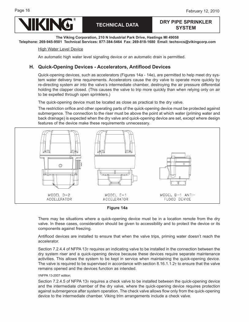
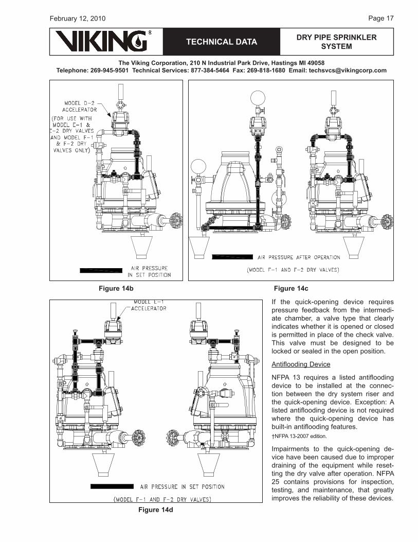
H. quick-Opening Devices - Accelerators, Antiflood Devicesquick-opening devices, such as accelerators (Figures 1�a - 1�e), are permitted to help meet dry sys-tem water delivery time requirements. Accelerators cause the dry valve to operate more quickly by re-directing system air into the valve’s intermediate chamber, destroying the air pressure differential holding the clapper closed. (This causes the valve to trip more quickly than when relying only on air to be expelled through open sprinklers.)
The quick-opening device must be located as close as practical to the dry valve.The restriction orifice and other operating parts of the quick-opening device must be protected against submergence. The connection to the riser must be above the point at which water (priming water and back drainage) is expected when the dry valve and quick-opening device are set, except where design features of the device make these requirements unnecessary.
There may be situations where a quick-opening device must be in a location remote from the dry valve. In these cases, consideration should be given to accessibility and to protect the device or its components against freezing.
Antiflood devices are installed to ensure that when the valve trips, priming water doesn’t reach the accelerator.
Section �.2.�.� of NFPA 1�† requires an indicating valve to be installed in the connection between the dry system riser and a quick-opening device because these devices require separate maintenance activities. This allows the system to be kept in service when maintaining the quick-opening device. The valve is required to be supervised in accordance with section 8.16.1.1.2† to ensure that the valve remains opened and the devices function as intended.†NFPA 1�-200� edition.
Section �.2.�.� of NFPA 1�† requires a check valve to be installed between the quick-opening device and the intermediate chamber of the dry valve, where the quick-opening device requires protection against submergence after system operation. The check valve allows flow only from the quick-opening device to the intermediate chamber. Viking trim arrangements include a check valve.
Figure 14a
TECHNICAL DATA
The Viking Corporation, 210 N Industrial Park Drive, Hastings MI 49058Telephone: 269-945-9501 Technical Services: 877-384-5464 Fax: 269-818-1680 Email: [email protected]
DRY PIPE SPRINkLER SYSTEM
Page 1�February 12, 2010
If the quick-opening device requires pressure feedback from the intermedi-ate chamber, a valve type that clearly indicates whether it is opened or closed is permitted in place of the check valve. This valve must be designed to be locked or sealed in the open position.
Antiflooding Device
NFPA 1� requires a listed antiflooding device to be installed at the connec-tion between the dry system riser and the quick-opening device. exception: A listed antiflooding device is not required where the quick-opening device has built-in antiflooding features.†NFPA 1�-200� edition.
Impairments to the quick-opening de-vice have been caused due to improper draining of the equipment while reset-ting the dry valve after operation. NFPA 2� contains provisions for inspection, testing, and maintenance, that greatly improves the reliability of these devices.
Figure 14b Figure 14c
Figure 14d
Page 18
TECHNICAL DATA
The Viking Corporation, 210 N Industrial Park Drive, Hastings MI 49058Telephone: 269-945-9501 Technical Services: 877-384-5464 Fax: 269-818-1680 Email: [email protected]
February 12, 2010
DRY PIPE SPRINkLER SYSTEM
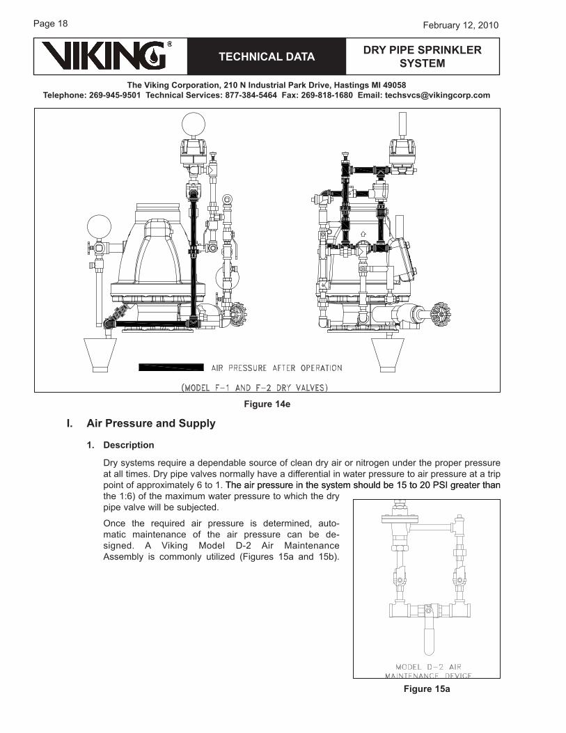
I. Air Pressure and Supply
1. Description
Dry systems require a dependable source of clean dry air or nitrogen under the proper pressure at all times. Dry pipe valves normally have a differential in water pressure to air pressure at a trip point of approximately 6 to 1. The air pressure in the system should be 1� to 20 PSI greater thanThe air pressure in the system should be 1� to 20 PSI greater than the 1:6) of the maximum water pressure to which the dry pipe valve will be subjected.
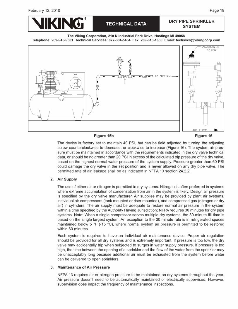
once the required air pressure is determined, auto-matic maintenance of the air pressure can be de-signed. A Viking Model D-2 Air Maintenance Assembly is commonly utilized (Figures 1�a and 1�b).
Figure 15a
Figure 14e
TECHNICAL DATA
The Viking Corporation, 210 N Industrial Park Drive, Hastings MI 49058Telephone: 269-945-9501 Technical Services: 877-384-5464 Fax: 269-818-1680 Email: [email protected]
DRY PIPE SPRINkLER SYSTEM
Page 1�February 12, 2010
The device is factory set to maintain �0 PSI, but can be field adjusted by turning the adjusting screw counterclockwise to decrease, or clockwise to increase (Figure 16). The system air pres-sure must be maintained in accordance with the requirements indicated in the dry valve technical data, or should be no greater than 20 PSI in excess of the calculated trip pressure of the dry valve, based on the highest normal water pressure of the system supply. Pressure greater than 60 PSI could damage the dry valve in the set position and is never allowed on any dry pipe valve. The permitted rate of air leakage shall be as indicated in NFPA 1� section 2�.2.2.
2. Air Supply
The use of either air or nitrogen is permitted in dry systems. Nitrogen is often preferred in systems where extreme accumulation of condensation from air in the system is likely. Design air pressure is specified by the dry valve manufacturer. Air supplies may be provided by plant air systems, individual air compressors (tank mounted or riser mounted), and compressed gas (nitrogen or dry air) in cylinders. The air supply must be adequate to restore normal air pressure in the system within a time specified by the Authority having jurisdiction; NFPA requires �0 minutes for dry pipe systems. Note: when a single compressor serves multiple dry systems, the �0-minute fill time is based on the single largest system. An exception to the �0 minute rule is in refrigerated spaces maintained below � °F (-1� °C), where normal system air pressure is permitted to be restored within 60 minutes.
each system is required to have an individual air maintenance device. Proper air regulation should be provided for all dry systems and is extremely important. If pressure is too low, the dry valve may accidentally trip when subjected to surges in water supply pressure. If pressure is too high, the time between the opening of a sprinkler and the flow of the water from the sprinkler may be unacceptably long because additional air must be exhausted from the system before water can be delivered to open sprinklers.
3. Maintenance of Air Pressure
NFPA 1� requires air or nitrogen pressure to be maintained on dry systems throughout the year. Air pressure doesn’t need to be automatically maintained or electrically supervised. however, supervision does impact the frequency of maintenance inspections.
Figure 16Figure 15b
Page 20
TECHNICAL DATA
The Viking Corporation, 210 N Industrial Park Drive, Hastings MI 49058Telephone: 269-945-9501 Technical Services: 877-384-5464 Fax: 269-818-1680 Email: [email protected]
February 12, 2010
DRY PIPE SPRINkLER SYSTEM
where the plant air system is manually operated and may be shut down over weekends or holi-days, an automatic maintenance air compressor may be used to maintain the required pressure. A maintenance air compressor may be used as a primary source on small dry systems (dry systems of 1�0 gallons capacity or smaller when using the Viking Model F-1 Maintenance Air Compressor).
The compressed air supply must be from a source available at all times. The compressor should draw its air supply from within the operating criteria allowed by the manufacturer of the compres-sor. Air piping should not be attached to the intake of the compressor unless acceptable to the compressor manufacturer and installed in accordance with NFPA 1� section �.�.2.�. Damage, air reduction, or reduced life expectancy can result if guidelines aren’t followed.
It is often desirable to provide a low air pressure alarm activated by an air pressure switch. The switch is set below the lowest design air pressure and above the expected tripping point of the dry valve in order to provide time to take corrective action in the event of low air pressure alarm.
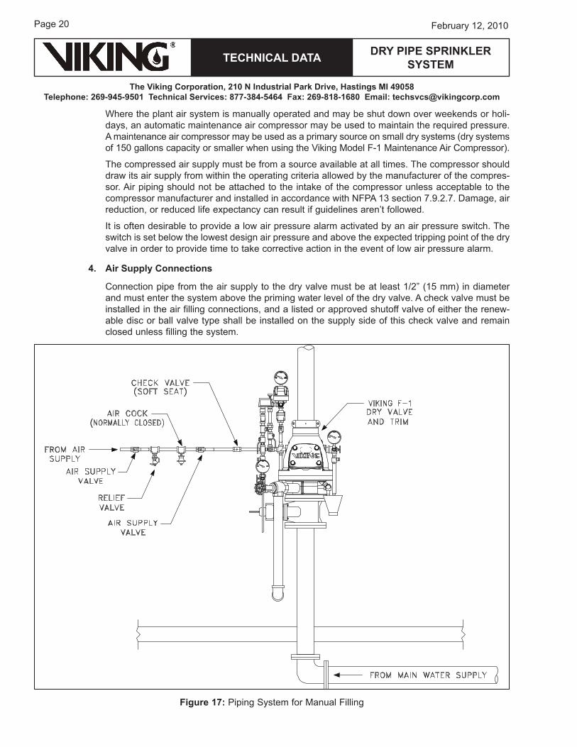
4. Air Supply Connections
Connection pipe from the air supply to the dry valve must be at least 1/2” (1� mm) in diameter and must enter the system above the priming water level of the dry valve. A check valve must be installed in the air filling connections, and a listed or approved shutoff valve of either the renew-able disc or ball valve type shall be installed on the supply side of this check valve and remain closed unless filling the system.
Figure 17: Piping System for Manual Filling
TECHNICAL DATA
The Viking Corporation, 210 N Industrial Park Drive, Hastings MI 49058Telephone: 269-945-9501 Technical Services: 877-384-5464 Fax: 269-818-1680 Email: [email protected]
DRY PIPE SPRINkLER SYSTEM
Page 21February 12, 2010
relief Valve
An approved relief valve must be provided between the air supply and shutoff valve and be set to relieve pressure no less than 10 PSI (0.� bar) in excess of system air pressure provided in NFPA 1� section �.2.6.6.1 and must not exceed the manufacturer’s limitations. Setting the value to 10 PSI (0.� bar) allows for small fluctuations in air pressure without the opening of the relief valve, while also ensuring that the system is not over-pressurized to the point that the dry valve doesn’t open and/or is damaged.
5. Design Considerations
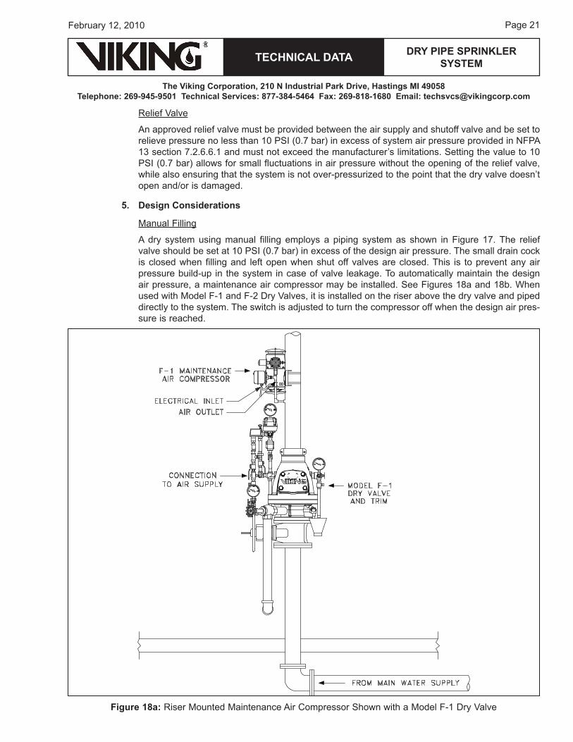
Manual Filling
A dry system using manual filling employs a piping system as shown in Figure 1�. The relief valve should be set at 10 PSI (0.� bar) in excess of the design air pressure. The small drain cock is closed when filling and left open when shut off valves are closed. This is to prevent any air pressure build-up in the system in case of valve leakage. To automatically maintain the design air pressure, a maintenance air compressor may be installed. See Figures 18a and 18b. when used with Model F-1 and F-2 Dry Valves, it is installed on the riser above the dry valve and piped directly to the system. The switch is adjusted to turn the compressor off when the design air pres-sure is reached.
Figure 18a: riser Mounted Maintenance Air Compressor Shown with a Model F-1 Dry Valve
Page 22
TECHNICAL DATA
The Viking Corporation, 210 N Industrial Park Drive, Hastings MI 49058Telephone: 269-945-9501 Technical Services: 877-384-5464 Fax: 269-818-1680 Email: [email protected]
February 12, 2010
DRY PIPE SPRINkLER SYSTEM
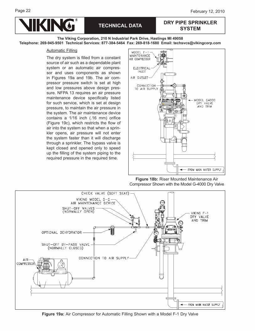
Automatic Filling
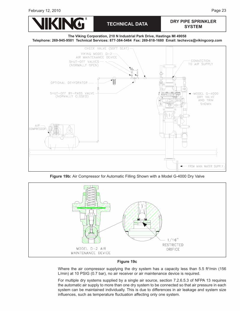
The dry system is filled from a constant source of air such as a dependable plant system or an automatic air compres-sor and uses components as shown in Figures 1�a and 1�b. The air com-pressor pressure switch is set at high and low pressures above design pres-sure. NFPA 1� requires an air pressure maintenance device specifically listed for such service, which is set at design pressure, to maintain the air pressure in the system. The air maintenance device contains a 1/16 inch (.16 mm) orifice (Figure 1�c), which restricts the flow of air into the system so that when a sprin-kler opens, air pressure will not enter the system faster than it will discharge through a sprinkler. The bypass valve is kept closed and opened only to speed up the filling of the system piping to the required pressure in the required time.
Figure 18b: riser Mounted Maintenance Air Compressor Shown with the Model G-�000 Dry Valve
Figure 19a: Air Compressor for Automatic Filling Shown with a Model F-1 Dry Valve
TECHNICAL DATA
The Viking Corporation, 210 N Industrial Park Drive, Hastings MI 49058Telephone: 269-945-9501 Technical Services: 877-384-5464 Fax: 269-818-1680 Email: [email protected]
DRY PIPE SPRINkLER SYSTEM
Page 2�February 12, 2010
where the air compressor supplying the dry system has a capacity less than �.� ft�/min (1�6 L/min) at 10 PSIG (0.� bar), no air receiver or air maintenance device is required.
For multiple dry systems supplied by a single air source, section �.2.6.�.� of NFPA 1� requires the automatic air supply to more than one dry system to be connected so that air pressure in each system can be maintained individually. This is due to differences in air leakage and system size influences, such as temperature fluctuation affecting only one system.
Figure 19b: Air Compressor for Automatic Filling Shown with a Model G-�000 Dry Valve
Figure 19c
Page 2�
TECHNICAL DATA
The Viking Corporation, 210 N Industrial Park Drive, Hastings MI 49058Telephone: 269-945-9501 Technical Services: 877-384-5464 Fax: 269-818-1680 Email: [email protected]
February 12, 2010
DRY PIPE SPRINkLER SYSTEM
A check valve or other positive backflow prevention device must be installed in the air supply to each system to prevent airflow or waterflow from one system to another, or into the air supply system (compressor), in the event of system operation.
Capacity of Air Compressor
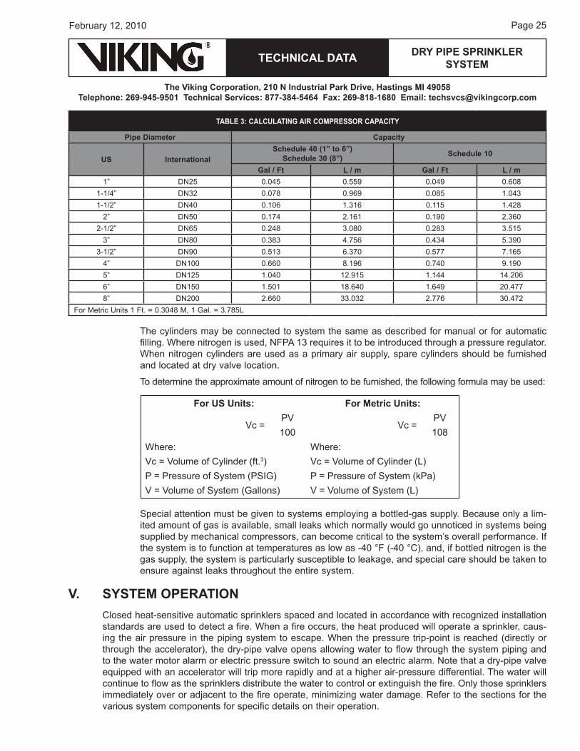
The capacity of the system must be calculated in order to furnish the correct size air compressor. Determine the total length of the different pipe sizes and use Table � to calculate the capacity.
The approximate free air capacity of a compressor suitable for pressurizing a system to �0 PSI (2.8 bar) in �0 minutes can be found by multiplying the system capacity as determined above by 0.012 for CFM (or by 0.08�8 for L/M).
Please see Appendix b for additional information on sizing air compressors, including an alterna-tive method of calculating the required air compressor size.
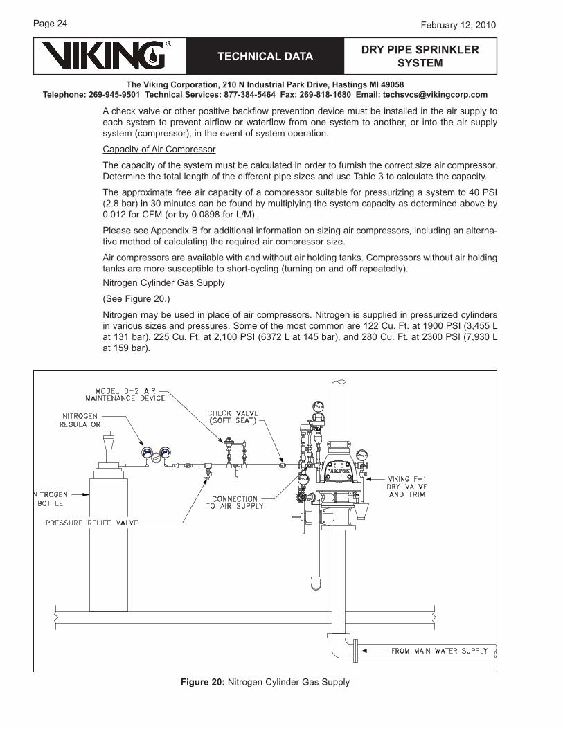
Air compressors are available with and without air holding tanks. Compressors without air holding tanks are more susceptible to short-cycling (turning on and off repeatedly).Nitrogen Cylinder Gas Supply
(See Figure 20.)
Nitrogen may be used in place of air compressors. Nitrogen is supplied in pressurized cylinders in various sizes and pressures. Some of the most common are 122 Cu. Ft. at 1�00 PSI (�,��� L at 1�1 bar), 22� Cu. Ft. at 2,100 PSI (6��2 L at 1�� bar), and 280 Cu. Ft. at 2�00 PSI (�,��0 L at 1�� bar).
Figure 20: Nitrogen Cylinder Gas Supply
TECHNICAL DATA
The Viking Corporation, 210 N Industrial Park Drive, Hastings MI 49058Telephone: 269-945-9501 Technical Services: 877-384-5464 Fax: 269-818-1680 Email: [email protected]
DRY PIPE SPRINkLER SYSTEM
Page 2�February 12, 2010
The cylinders may be connected to system the same as described for manual or for automatic filling. where nitrogen is used, NFPA 1� requires it to be introduced through a pressure regulator.when nitrogen cylinders are used as a primary air supply, spare cylinders should be furnished and located at dry valve location.
To determine the approximate amount of nitrogen to be furnished, the following formula may be used:
Special attention must be given to systems employing a bottled-gas supply. because only a lim-ited amount of gas is available, small leaks which normally would go unnoticed in systems being supplied by mechanical compressors, can become critical to the system’s overall performance. If the system is to function at temperatures as low as -�0 °F (-�0 °C), and, if bottled nitrogen is the gas supply, the system is particularly susceptible to leakage, and special care should be taken to ensure against leaks throughout the entire system.
V. SYSTEM OPERATIONClosed heat-sensitive automatic sprinklers spaced and located in accordance with recognized installation standards are used to detect a fire. when a fire occurs, the heat produced will operate a sprinkler, caus-ing the air pressure in the piping system to escape. when the pressure trip-point is reached (directly or through the accelerator), the dry-pipe valve opens allowing water to flow through the system piping and to the water motor alarm or electric pressure switch to sound an electric alarm. Note that a dry-pipe valve equipped with an accelerator will trip more rapidly and at a higher air-pressure differential. The water will continue to flow as the sprinklers distribute the water to control or extinguish the fire. only those sprinklers immediately over or adjacent to the fire operate, minimizing water damage. refer to the sections for the various system components for specific details on their operation.
For uS units: For Metric units:
Vc =PV
Vc =PV
100 108where: where:Vc = Volume of Cylinder (ft.�) Vc = Volume of Cylinder (L)P = Pressure of System (PSIG) P = Pressure of System (kPa)V = Volume of System (Gallons) V = Volume of System (L)
TABLE 3: CALCuLATING AIR COMPRESSOR CAPACITY
Pipe Diameter Capacity
uS InternationalSchedule 40 (1” to 6”)
Schedule 30 (8”) Schedule 10
Gal / Ft L / m Gal / Ft L / m1” DN2� 0.0�� 0.��� 0.0�� 0.608
1-1/�” DN�2 0.0�8 0.�6� 0.08� 1.0��1-1/2” DN�0 0.106 1.�16 0.11� 1.�28
2” DN�0 0.1�� 2.161 0.1�0 2.�602-1/2” DN6� 0.2�8 �.080 0.28� �.�1�
�” DN80 0.�8� �.��6 0.��� �.��0�-1/2” DN�0 0.�1� 6.��0 0.��� �.16�
�” DN100 0.660 8.1�6 0.��0 �.1�0�” DN12� 1.0�0 12.�1� 1.1�� 1�.2066” DN1�0 1.�01 18.6�0 1.6�� 20.���8” DN200 2.660 ��.0�2 2.��6 �0.��2
For Metric units 1 Ft. = 0.�0�8 M, 1 Gal. = �.�8�L
Page 26
TECHNICAL DATA
The Viking Corporation, 210 N Industrial Park Drive, Hastings MI 49058Telephone: 269-945-9501 Technical Services: 877-384-5464 Fax: 269-818-1680 Email: [email protected]
February 12, 2010
DRY PIPE SPRINkLER SYSTEM
A. DRY VALVE OPERATIONIn Viking dry pipe systems, an approximately 6-1 mechanical ratio allows moderate air pressure to control higher water supply pressure. The recommended pressure for a particular system depends on the water supply itself (refer to Figure �a on page � and �a on page 6). Viking’s technical data sets the minimum required and maximum recommended air pressure. The air pressure provided needs to offset the highest possible water pressure the system will see.
1. Model F-1 and F-2 Dry Valves
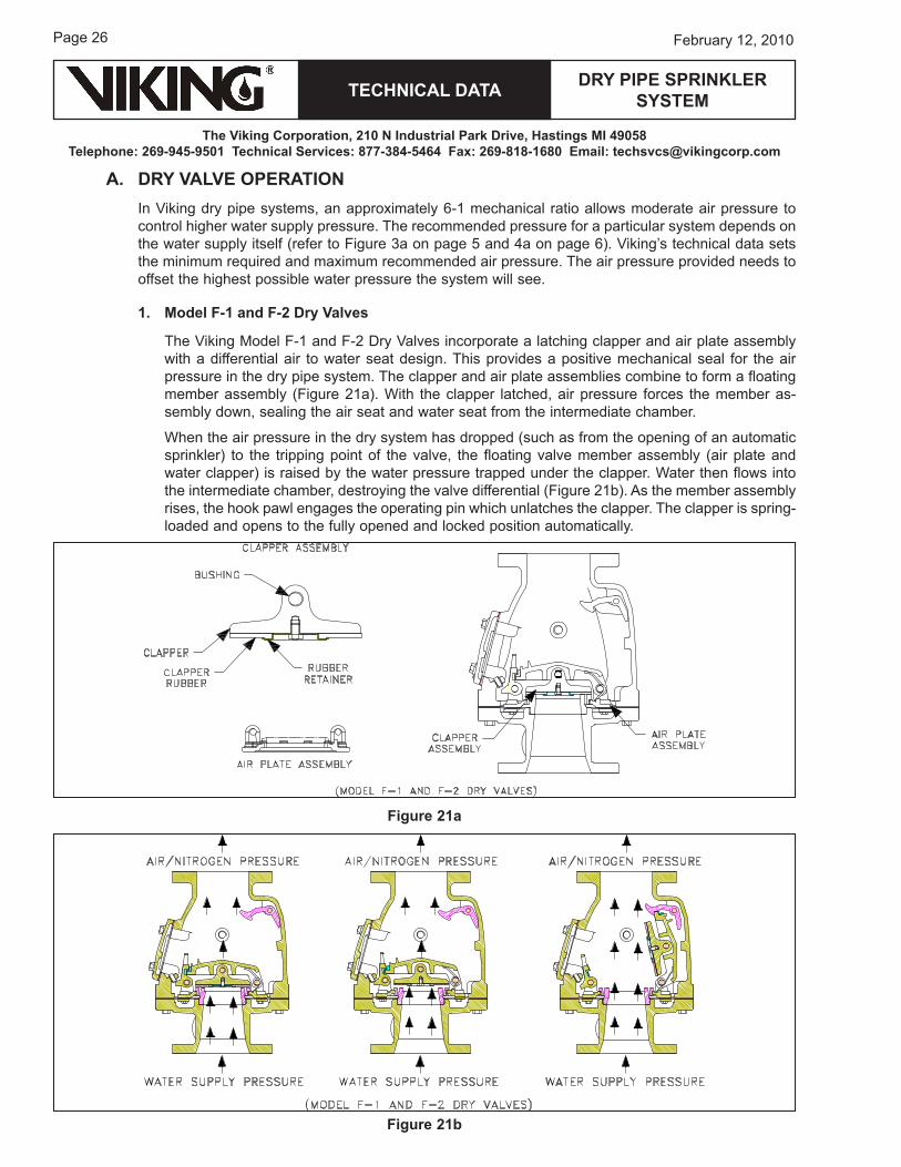
The Viking Model F-1 and F-2 Dry Valves incorporate a latching clapper and air plate assembly with a differential air to water seat design. This provides a positive mechanical seal for the air pressure in the dry pipe system. The clapper and air plate assemblies combine to form a floating member assembly (Figure 21a). with the clapper latched, air pressure forces the member as-sembly down, sealing the air seat and water seat from the intermediate chamber.
when the air pressure in the dry system has dropped (such as from the opening of an automatic sprinkler) to the tripping point of the valve, the floating valve member assembly (air plate and water clapper) is raised by the water pressure trapped under the clapper. water then flows into the intermediate chamber, destroying the valve differential (Figure 21b). As the member assembly rises, the hook pawl engages the operating pin which unlatches the clapper. The clapper is spring-loaded and opens to the fully opened and locked position automatically.
Figure 21a
Figure 21b
TECHNICAL DATA
The Viking Corporation, 210 N Industrial Park Drive, Hastings MI 49058Telephone: 269-945-9501 Technical Services: 877-384-5464 Fax: 269-818-1680 Email: [email protected]
DRY PIPE SPRINkLER SYSTEM
Page 2�February 12, 2010
2. Model G-2000, G-3000, and G-4000 Dry Valves
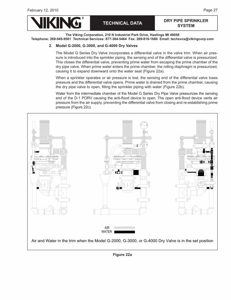
The Model G Series Dry Valve incorporates a differential valve in the valve trim. when air pres-sure is introduced into the sprinkler piping, the sensing end of the differential valve is pressurized. This closes the differential valve, preventing prime water from escaping the prime chamber of the dry pipe valve. when prime water enters the prime chamber, the rolling diaphragm is pressurized, causing it to expand downward onto the water seat (Figure 22a).
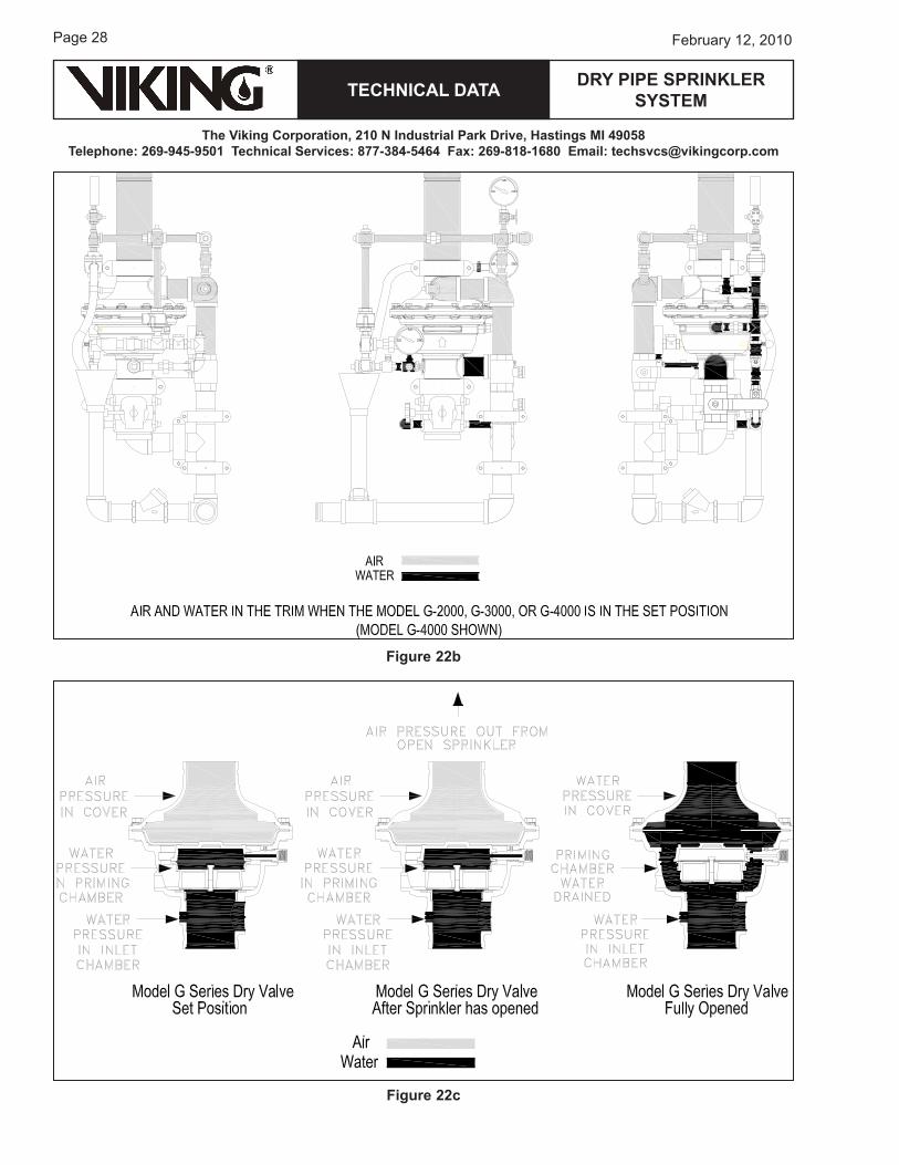
when a sprinkler operates or air pressure is lost, the sensing end of the differential valve loses pressure and the differential valve opens. Prime water is drained from the prime chamber, causing the dry pipe valve to open, filling the sprinkler piping with water (Figure 22b).
water from the intermediate chamber of the Model G Series Dry Pipe Valve pressurizes the sensing end of the D-1 PorV causing the anti-flood device to open. The open anti-flood device vents air pressure from the air supply, preventing the differential valve from closing and re-establishing prime pressure (Figure 22c).
Figure 22a
Page 28
TECHNICAL DATA
The Viking Corporation, 210 N Industrial Park Drive, Hastings MI 49058Telephone: 269-945-9501 Technical Services: 877-384-5464 Fax: 269-818-1680 Email: [email protected]
February 12, 2010
DRY PIPE SPRINkLER SYSTEM
Figure 22b
Figure 22c
TECHNICAL DATA
The Viking Corporation, 210 N Industrial Park Drive, Hastings MI 49058Telephone: 269-945-9501 Technical Services: 877-384-5464 Fax: 269-818-1680 Email: [email protected]
DRY PIPE SPRINkLER SYSTEM
Page 2�February 12, 2010
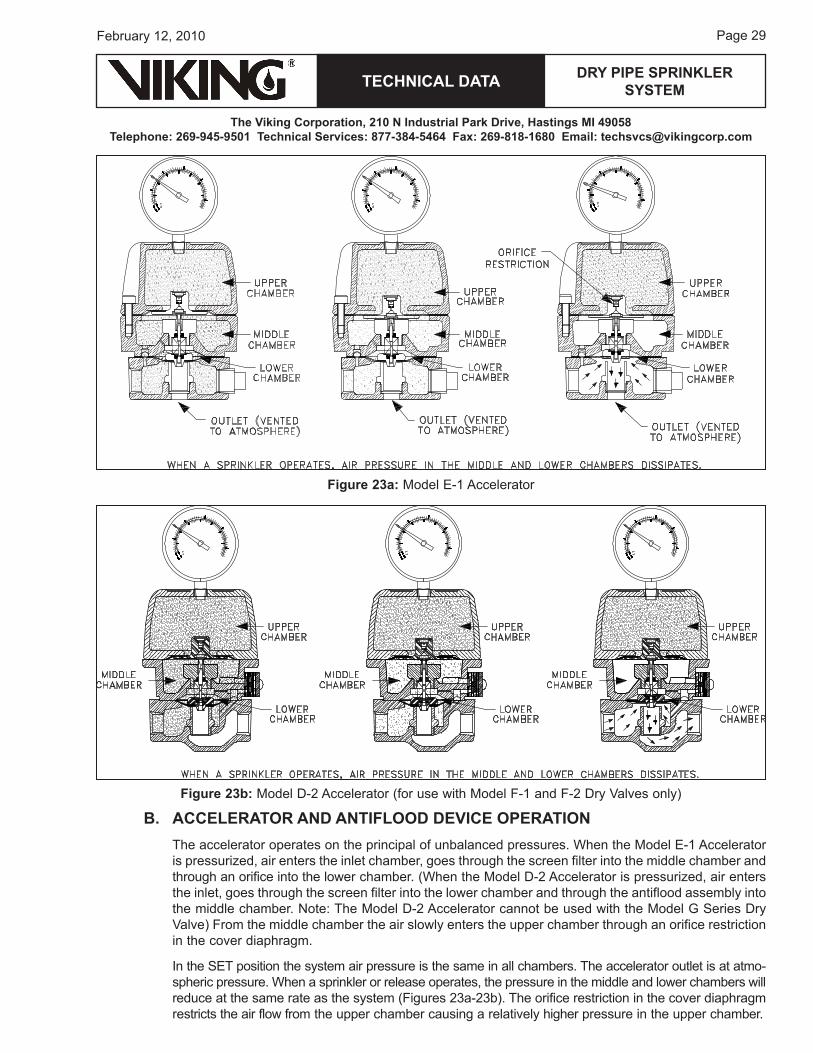
B. ACCELERATOR AND ANTIFLOOD DEVICE OPERATIONThe accelerator operates on the principal of unbalanced pressures. when the Model e-1 Accelerator is pressurized, air enters the inlet chamber, goes through the screen filter into the middle chamber and through an orifice into the lower chamber. (when the Model D-2 Accelerator is pressurized, air enters the inlet, goes through the screen filter into the lower chamber and through the antiflood assembly into the middle chamber. Note: The Model D-2 Accelerator cannot be used with the Model G Series Dry Valve) From the middle chamber the air slowly enters the upper chamber through an orifice restriction in the cover diaphragm.
In the SeT position the system air pressure is the same in all chambers. The accelerator outlet is at atmo-spheric pressure. when a sprinkler or release operates, the pressure in the middle and lower chambers will reduce at the same rate as the system (Figures 2�a-2�b). The orifice restriction in the cover diaphragm restricts the air flow from the upper chamber causing a relatively higher pressure in the upper chamber.
Figure 23a: Model e-1 Accelerator
Figure 23b: Model D-2 Accelerator (for use with Model F-1 and F-2 Dry Valves only)
Page �0
TECHNICAL DATA
The Viking Corporation, 210 N Industrial Park Drive, Hastings MI 49058Telephone: 269-945-9501 Technical Services: 877-384-5464 Fax: 269-818-1680 Email: [email protected]
February 12, 2010
DRY PIPE SPRINkLER SYSTEM
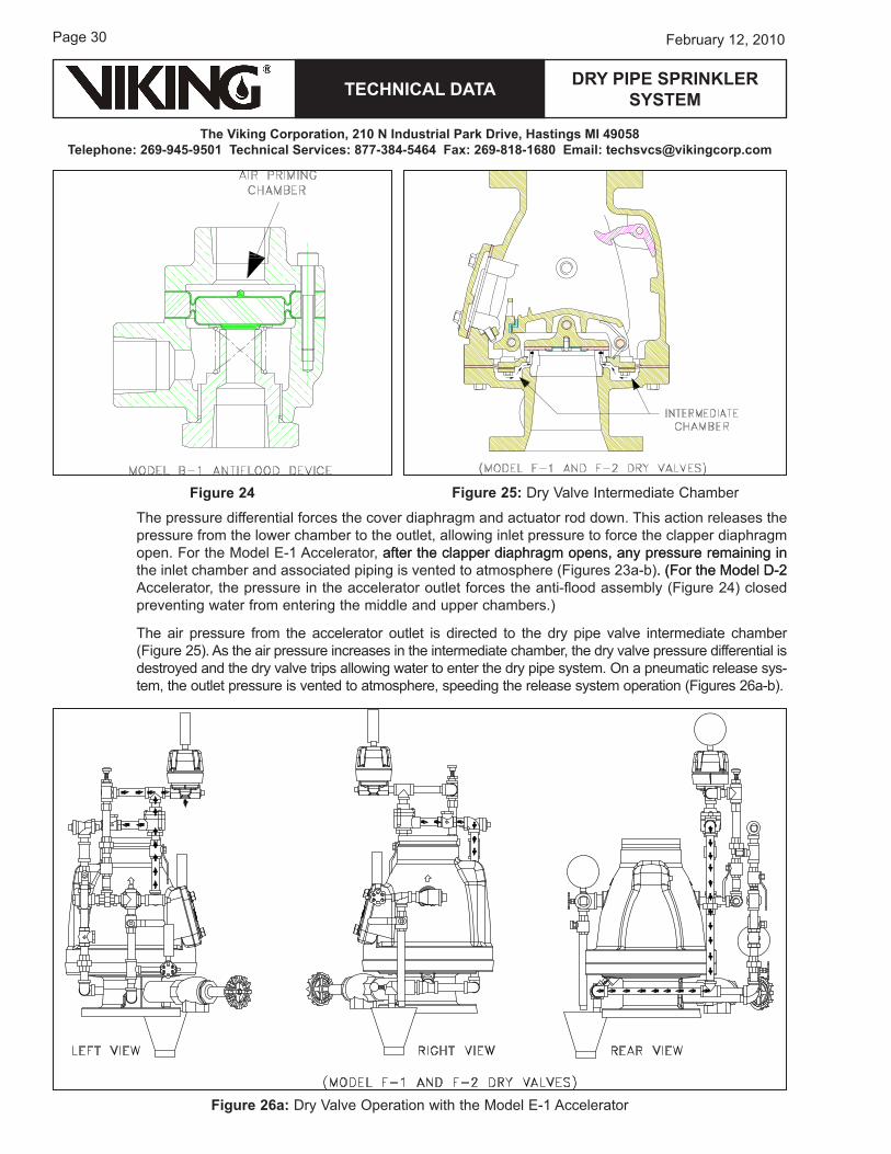
The pressure differential forces the cover diaphragm and actuator rod down. This action releases the pressure from the lower chamber to the outlet, allowing inlet pressure to force the clapper diaphragm open. For the Model e-1 Accelerator, after the clapper diaphragm opens, any pressure remaining inafter the clapper diaphragm opens, any pressure remaining in the inlet chamber and associated piping is vented to atmosphere (Figures 2�a-b). (For the Model D-2. (For the Model D-2 Accelerator, the pressure in the accelerator outlet forces the anti-flood assembly (Figure 2�) closed preventing water from entering the middle and upper chambers.)
The air pressure from the accelerator outlet is directed to the dry pipe valve intermediate chamber (Figure 2�). As the air pressure increases in the intermediate chamber, the dry valve pressure differential is destroyed and the dry valve trips allowing water to enter the dry pipe system. on a pneumatic release sys-tem, the outlet pressure is vented to atmosphere, speeding the release system operation (Figures 26a-b).
Figure 25: Dry Valve Intermediate ChamberFigure 24
Figure 26a: Dry Valve operation with the Model e-1 Accelerator

TECHNICAL DATA
The Viking Corporation, 210 N Industrial Park Drive, Hastings MI 49058Telephone: 269-945-9501 Technical Services: 877-384-5464 Fax: 269-818-1680 Email: [email protected]
DRY PIPE SPRINkLER SYSTEM
Page �1February 12, 2010
Figure 26b: Dry Valve operation with the Model D-2 Accelerator (for use with Model F-1 and F-2 Dry Valves only)
VI. PLACING THE SYSTEM IN SERVICE1. Shut off the water supply control valve (Figure 2�).
Check the entire system to ensure all piping, sprinklers, and piping components are in serv-iceable condition. replace any opened sprin-klers with the same type and temperature rating. For systems with the Model G Series Dry Valve, close the prime valve. Drain all low points of the system, then close all drain valves. (on a drum drip, the upper drain valve remains open and the lower is closed.) For systems with the G Series Dry Valve, open the main drain valve and drain all water from the dry pipe system. If the system has operated or if water has entered the system, allow enough time to completely drain the sys-tem, and then close the main drain valve. For air check system or auxiliary dry systems, drain the dry portion of the system only.
2. If an accelerator is used, with no pressure on the system, observe the air gauge on the accelera-tor. The gauge must read zero. (It may be neces-sary to loosen the air gauge to vent the trapped air pressure in the upper chamber).
�. Set the Model F-1 or F-2 Dry Valve: a. open the test drain valve and remove the hand-hole cover. wipe the valve seats clean
(Figure 28), remove any mineral deposits, and check all moving parts to see that they move freely. remove and replace any damaged or worn parts. Never use lubricants on any of the moving parts inside the valve. Pull the clapper down into the CLoSeD position (hold while inserting wrench handle through hook-pawl assembly hole), slide wrench handle through hole
Figure 27
Page �2
TECHNICAL DATA
The Viking Corporation, 210 N Industrial Park Drive, Hastings MI 49058Telephone: 269-945-9501 Technical Services: 877-384-5464 Fax: 269-818-1680 Email: [email protected]
February 12, 2010
DRY PIPE SPRINkLER SYSTEM
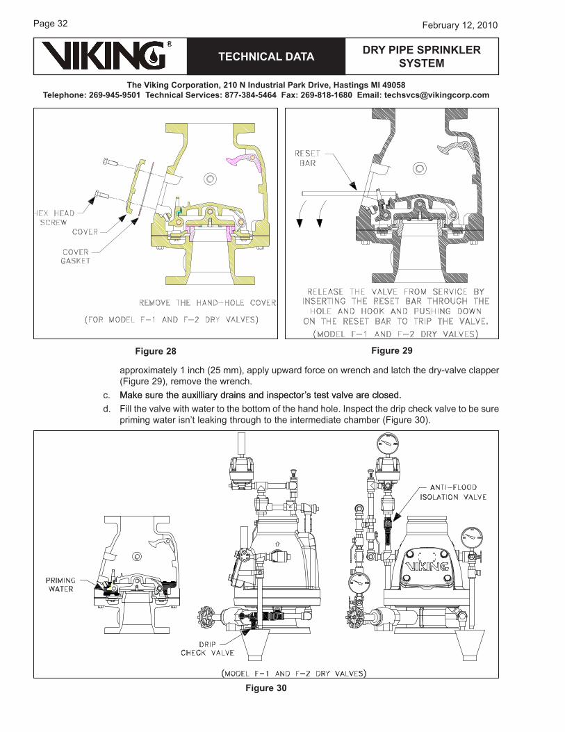
approximately 1 inch (2� mm), apply upward force on wrench and latch the dry-valve clapper (Figure 2�), remove the wrench.
c. Make sure the auxilliary drains and inspector’s test valve are closed.Make sure the auxilliary drains and inspector’s test valve are closed. d. Fill the valve with water to the bottom of the hand hole. Inspect the drip check valve to be sure
priming water isn’t leaking through to the intermediate chamber (Figure �0).
Figure 28 Figure 29
Figure 30
TECHNICAL DATA
The Viking Corporation, 210 N Industrial Park Drive, Hastings MI 49058Telephone: 269-945-9501 Technical Services: 877-384-5464 Fax: 269-818-1680 Email: [email protected]
DRY PIPE SPRINkLER SYSTEM
Page ��February 12, 2010
e. replace the hand-hole cover. f. open the air supply to the system, allowing it to build up the recommended air pressure
setting. Again, depress the drip check valve. Verify that neither air nor water pressure is ac-cumulating in the intermediate chamber. If the dry pipe system includes an anti-flood device and an accelerator assembly, the anti-flood isolation valve must be closed while pressuring the system and open and secure the valve immediately after (Figure �0). (This valve should never be closed, except briefly when pressurizing the system.)
g. wait until the accelerator air-pressure gauge reads the same as the dry pipe valve. h. open water supply control valves slowly.i. Close the dry pipe valve main drain valve slowly.j. Make sure the alarm test shut-off valve is in the ALArM position.OR
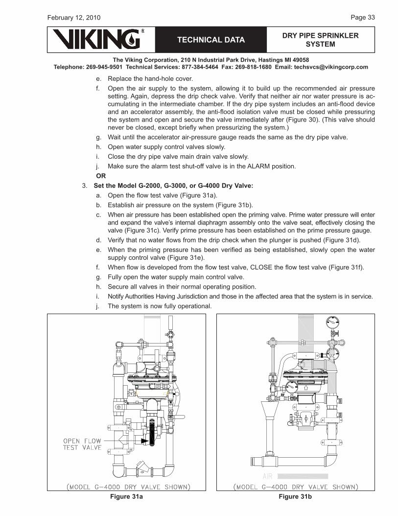
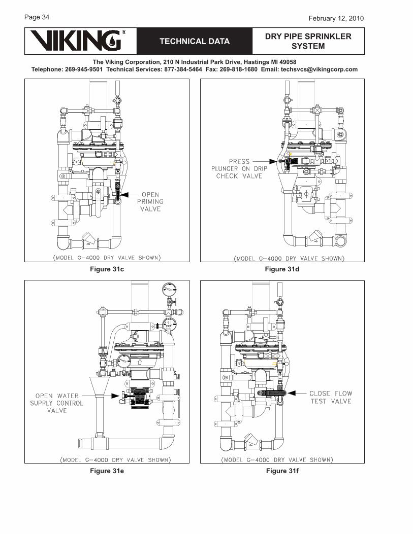
�. Set the Model G-2000, G-3000, or G-4000 Dry Valve: a. open the flow test valve (Figure �1a).b. establish air pressure on the system (Figure �1b).c. when air pressure has been established open the priming valve. Prime water pressure will enter
and expand the valve’s internal diaphragm assembly onto the valve seat, effectively closing the valve (Figure �1c). Verify prime pressure has been established on the prime pressure gauge.
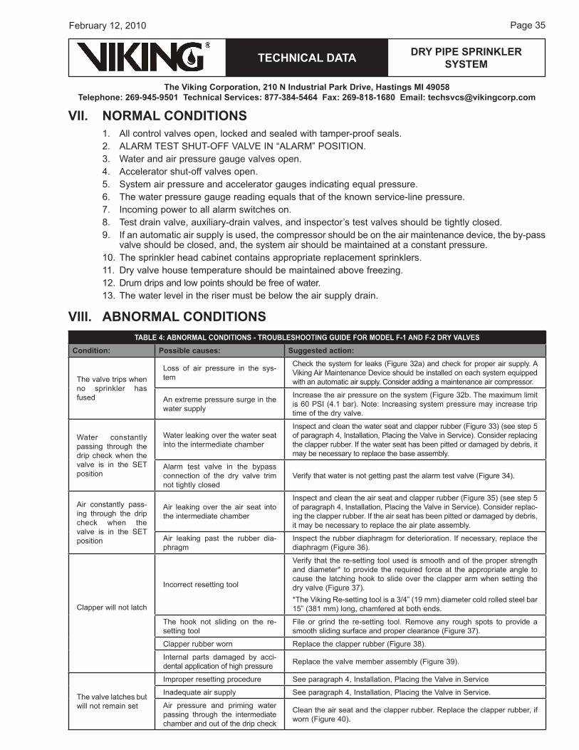
d. Verify that no water flows from the drip check when the plunger is pushed (Figure �1d).e. when the priming pressure has been verified as being established, slowly open the water
supply control valve (Figure �1e).f. when flow is developed from the flow test valve, CLoSe the flow test valve (Figure �1f).g. Fully open the water supply main control valve.h. Secure all valves in their normal operating position.i. Notify Authorities having jurisdiction and those in the affected area that the system is in service.j. The system is now fully operational.
Figure 31a Figure 31b
Page ��
TECHNICAL DATA
The Viking Corporation, 210 N Industrial Park Drive, Hastings MI 49058Telephone: 269-945-9501 Technical Services: 877-384-5464 Fax: 269-818-1680 Email: [email protected]
February 12, 2010
DRY PIPE SPRINkLER SYSTEM
Figure 31c Figure 31d
Figure 31e Figure 31f
TECHNICAL DATA
The Viking Corporation, 210 N Industrial Park Drive, Hastings MI 49058Telephone: 269-945-9501 Technical Services: 877-384-5464 Fax: 269-818-1680 Email: [email protected]
DRY PIPE SPRINkLER SYSTEM
Page ��February 12, 2010
VII. NORMAL CONDITIONS1. All control valves open, locked and sealed with tamper-proof seals.2. ALArM TeST ShuT-oFF VALVe IN “ALArM” PoSITIoN.�. water and air pressure gauge valves open.�. Accelerator shut-off valves open.�. System air pressure and accelerator gauges indicating equal pressure.6. The water pressure gauge reading equals that of the known service-line pressure.�. Incoming power to all alarm switches on.8. Test drain valve, auxiliary-drain valves, and inspector’s test valves should be tightly closed.�. If an automatic air supply is used, the compressor should be on the air maintenance device, the by-pass
valve should be closed, and, the system air should be maintained at a constant pressure.10. The sprinkler head cabinet contains appropriate replacement sprinklers.11. Dry valve house temperature should be maintained above freezing.12. Drum drips and low points should be free of water.1�. The water level in the riser must be below the air supply drain.
VIII. ABNORMAL CONDITIONSTABLE 4: ABNORMAL CONDITIONS - TROuBLESHOOTING GuIDE FOR MODEL F-1 AND F-2 DRY VALVES
Condition: Possible causes: Suggested action:
The valve trips when no sprinkler has fused
Loss of air pressure in the sys-tem
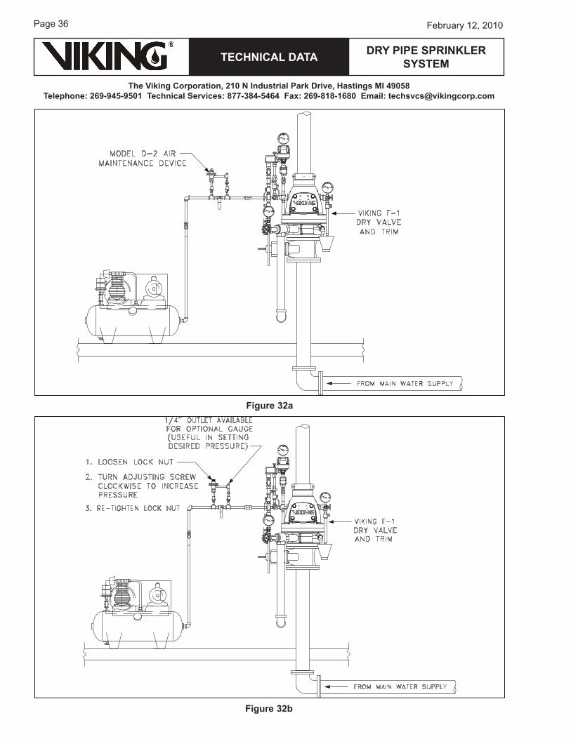
Check the system for leaks (Figure �2a) and check for proper air supply. A Viking Air Maintenance Device should be installed on each system equipped with an automatic air supply. Consider adding a maintenance air compressor.
An extreme pressure surge in the water supply
Increase the air pressure on the system (Figure �2b. The maximum limit is 60 PSI (�.1 bar). Note: Increasing system pressure may increase trip time of the dry valve.
water constantly passing through the drip check when the valve is in the SeT position
water leaking over the water seat into the intermediate chamber
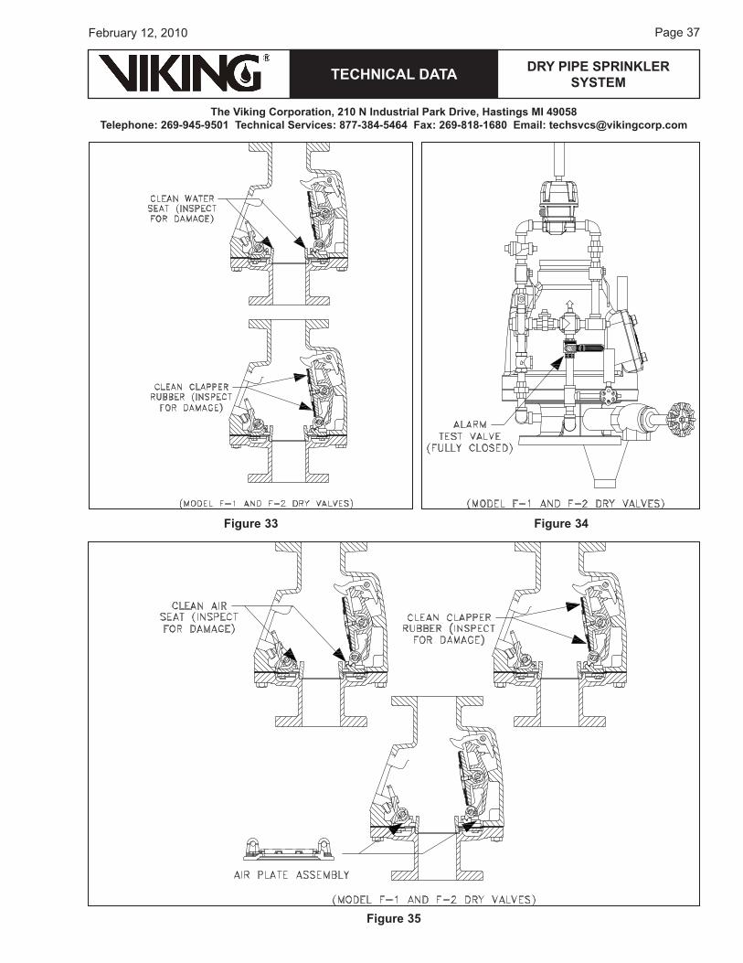
Inspect and clean the water seat and clapper rubber (Figure ��) (see step � of paragraph �, Installation, Placing the Valve in Service). Consider replacing the clapper rubber. If the water seat has been pitted or damaged by debris, it may be necessary to replace the base assembly.
Alarm test valve in the bypass connection of the dry valve trim not tightly closed
Verify that water is not getting past the alarm test valve (Figure ��).
Air constantly pass-ing through the drip check when the valve is in the SeT position
Air leaking over the air seat into the intermediate chamber
Inspect and clean the air seat and clapper rubber (Figure ��) (see step � of paragraph �, Installation, Placing the Valve in Service). Consider replac-ing the clapper rubber. If the air seat has been pitted or damaged by debris, it may be necessary to replace the air plate assembly.
Air leaking past the rubber dia-phragm
Inspect the rubber diaphragm for deterioration. If necessary, replace the diaphragm (Figure �6).
Clapper will not latch
Incorrect resetting tool
Verify that the re-setting tool used is smooth and of the proper strength and diameter* to provide the required force at the appropriate angle to cause the latching hook to slide over the clapper arm when setting the dry valve (Figure ��).*The Viking re-setting tool is a �/�” (1� mm) diameter cold rolled steel bar 1�” (�81 mm) long, chamfered at both ends.
The hook not sliding on the re-setting tool
File or grind the re-setting tool. remove any rough spots to provide a smooth sliding surface and proper clearance (Figure ��).
Clapper rubber worn replace the clapper rubber (Figure �8).
Internal parts damaged by acci-dental application of high pressure replace the valve member assembly (Figure ��).
The valve latches but will not remain set
Improper resetting procedure See paragraph �, Installation, Placing the Valve in Service
Inadequate air supply See paragraph �, Installation, Placing the Valve in Service.
Air pressure and priming water passing through the intermediate chamber and out of the drip check
Clean the air seat and the clapper rubber. replace the clapper rubber, if worn (Figure �0).
Page �6
TECHNICAL DATA
The Viking Corporation, 210 N Industrial Park Drive, Hastings MI 49058Telephone: 269-945-9501 Technical Services: 877-384-5464 Fax: 269-818-1680 Email: [email protected]
February 12, 2010
DRY PIPE SPRINkLER SYSTEM
Figure 32a
Figure 32b
TECHNICAL DATA
The Viking Corporation, 210 N Industrial Park Drive, Hastings MI 49058Telephone: 269-945-9501 Technical Services: 877-384-5464 Fax: 269-818-1680 Email: [email protected]
DRY PIPE SPRINkLER SYSTEM
Page ��February 12, 2010
Figure 33 Figure 34
Figure 35
Page �8
TECHNICAL DATA
The Viking Corporation, 210 N Industrial Park Drive, Hastings MI 49058Telephone: 269-945-9501 Technical Services: 877-384-5464 Fax: 269-818-1680 Email: [email protected]
February 12, 2010
DRY PIPE SPRINkLER SYSTEM
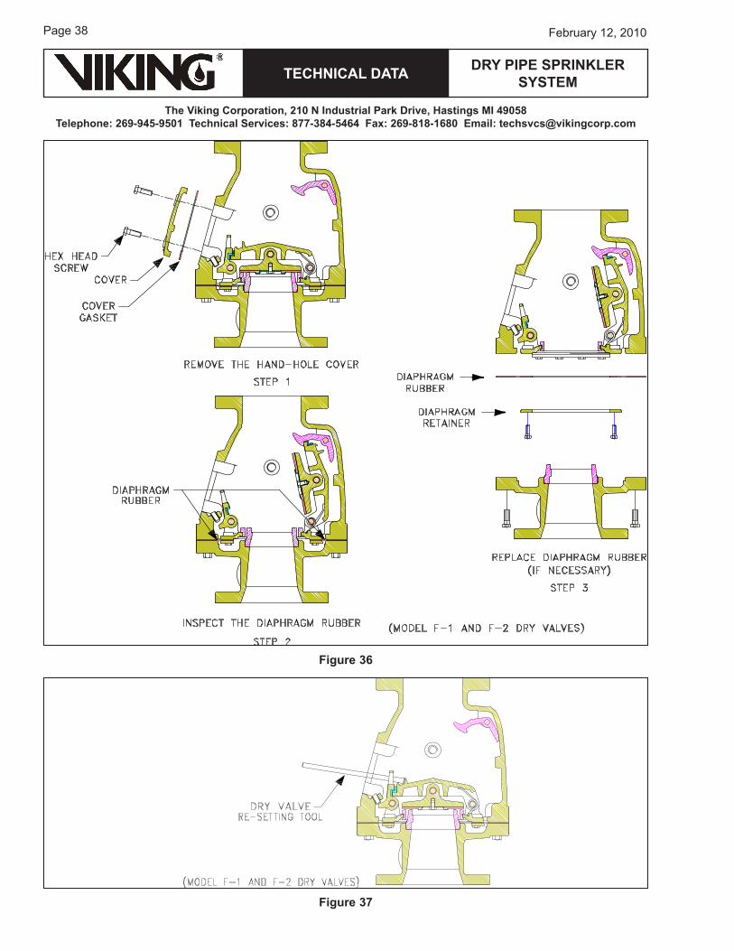
Figure 36
Figure 37
TECHNICAL DATA
The Viking Corporation, 210 N Industrial Park Drive, Hastings MI 49058Telephone: 269-945-9501 Technical Services: 877-384-5464 Fax: 269-818-1680 Email: [email protected]
DRY PIPE SPRINkLER SYSTEM
Page ��February 12, 2010
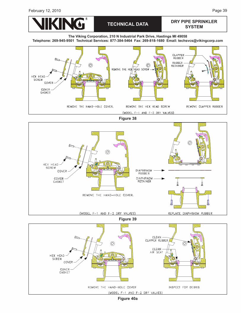
Figure 38
Figure 39
Figure 40a
Page �0
TECHNICAL DATA
The Viking Corporation, 210 N Industrial Park Drive, Hastings MI 49058Telephone: 269-945-9501 Technical Services: 877-384-5464 Fax: 269-818-1680 Email: [email protected]
February 12, 2010
DRY PIPE SPRINkLER SYSTEM
Ix. INSPECTIONS, TESTS, AND MAINTENANCENOTICE: THE OWNER IS RESPONSIBLE FOR MAINTAINING THE FIRE PROTECTION SYSTEM AND DEVICES IN PROPER OPERATING CONDITION.
The Viking Dry Valve and trim must be kept free of foreign matter, freezing conditions, corrosive atmos-pheres, contaminated water supplies, and any condition that could impair its operation or damage the device.
It is imperative that the system be inspected and tested on a regular basis. The frequency of the inspec-tions may vary due to contaminated water supplies, corrosive water supplies, corrosive atmospheres, as well as the condition of the air supply to the system.
For minimum maintenance and inspection requirements, refer to NFPA 2�. In addition, the Authority having jurisdiction may have additional maintenance, testing, and inspection requirements that must be followed.
CAuTION: The Viking dry pipe valve, like any differential type dry valve, must not be subjected to hydro-static test pressure with the clapper in the set position.
WARNING: ANY SYSTEM MAINTENANCE THAT INVOLVES PLACING A CONTROL VALVE OR DETECTION SYSTEM OuT OF SERVICE MAY ELIMINATE THE FIRE PROTECTION CAPABILITIES OF THAT SYS-TEM. PRIOR TO PROCEEDING, NOTIFY ALL AuTHORITIES HAVING JuRISDICTION. CONSIDERATION SHOuLD BE GIVEN TO EMPLOYMENT OF A FIRE PATROL IN THE AFFECTED AREAS.
A. Model F-1 and F-2 Dry Valve Maintenance (refer to Figures 28-�2.)
WARNING: PRIOR TO SERVICING INTERNAL OPERATING PARTS OF THE DRY VALVE, TAkE THE FOLLOWING PRECAuTIONS.
1. Close the water supply main control valve, placing the system out of service.2. open the main drain located in the base of the dry valve.�. Close the air (or nitrogen) supply to the dry system piping.�. relieve all pressure from the dry system piping. If the system has operated, open all auxiliary
drains and the system test valve to allow the system to drain completely.
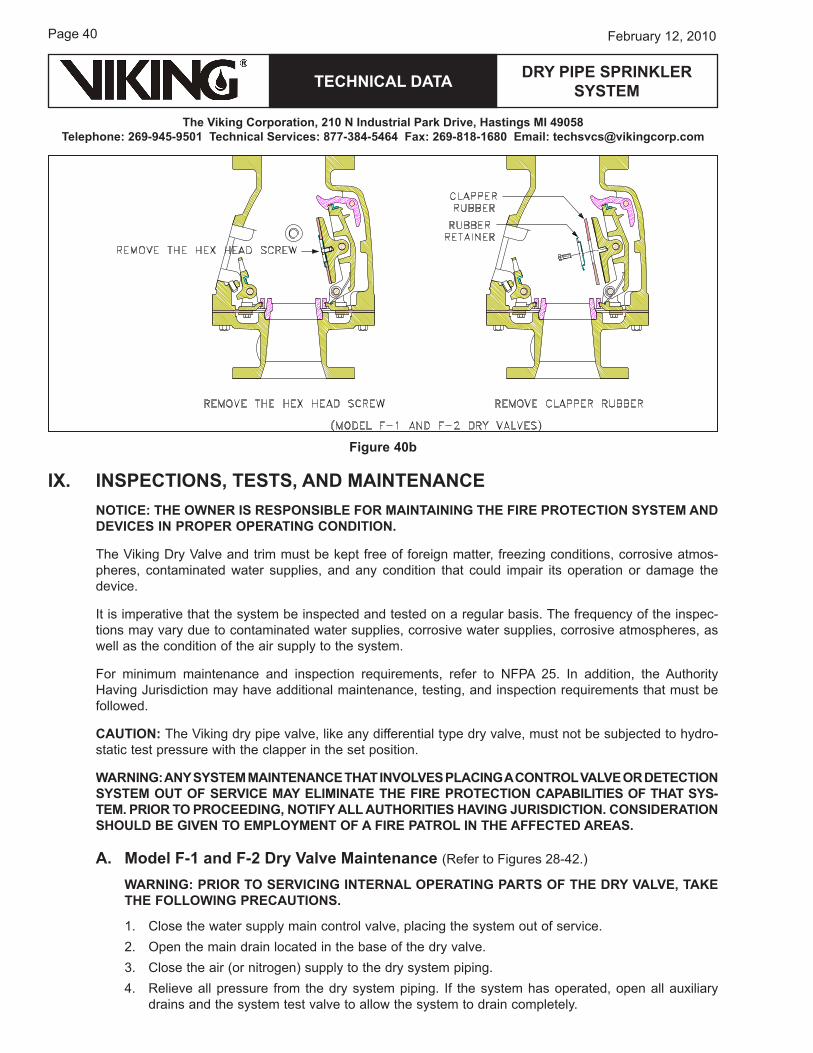
Figure 40b
TECHNICAL DATA
The Viking Corporation, 210 N Industrial Park Drive, Hastings MI 49058Telephone: 269-945-9501 Technical Services: 877-384-5464 Fax: 269-818-1680 Email: [email protected]
DRY PIPE SPRINkLER SYSTEM
Page �1February 12, 2010
�. use a 1�/16” wrench to loosen and remove hand-hole cover bolts and remove hand-hole cover (Figure 28).
CAuTION: CLAPPER ARM ASSEMBLY AND CLAPPER ASSEMBLY IS SPRING LOADED TO OPEN. NEVER PLACE HANDS INSIDE THE DRY VALVE IF THE CLAPPER ASSEMBLY IS LATCHED CLOSED.
NOTE: Do NoT subject the dry valve to hydrostatic test pressure with the clapper in the set position. Always be sure to trip the valve so that it is latched open.
6. release latched (set) clapper assembly for service:a. Insert the re-setting tool through the hole in hook assembly, across the cast fulcrum on top
of clapper arm assembly until the re-setting tool contacts the stopping boss on top of clapper arm assembly.
b. Apply a downward force on the end (outside the valve) of the re-setting tool. hook assembly will slide toward the hand-hole and off clapper arm assembly. The clapper arm assembly and clapper assembly will forcefully open, impact against latch, and be trapped in the open posi-tion (Figure 2�).
CAuTION: NEVER APPLY ANY LuBRICANT TO SEATS, GASkETS, OR ANY INTERNAL OP-ERATING PARTS OF THE DRY VALVE. PETROLEuM-BASED GREASE OR OIL WILL DAMAGE RuBBER COMPONENTS AND MAY PREVENT PROPER OPERATION OF THE DRY VALVE.
recommended practice: when performing maintenance inside the dry valve with the clapper in the open position, cover the opening to prevent tools or parts from dropping onto the seat or into the waterway.
If air or water is leaking into the intermediate chamber and out of the drip check, even after cleaning the seat, the clapper rubber may need to be replaced.
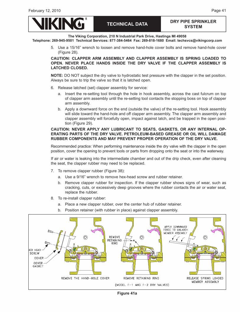
�. To remove clapper rubber (Figure �8):a. use a �/16” wrench to remove hex-head screw and rubber retainer.b. remove clapper rubber for inspection. If the clapper rubber shows signs of wear, such as
cracking, cuts, or excessively deep grooves where the rubber contacts the air or water seat, replace the rubber.
8. To re-install clapper rubber:a. Place a new clapper rubber, over the center hub of rubber retainer.b. Position retainer (with rubber in place) against clapper assembly.
Figure 41a
Page �2
TECHNICAL DATA
The Viking Corporation, 210 N Industrial Park Drive, Hastings MI 49058Telephone: 269-945-9501 Technical Services: 877-384-5464 Fax: 269-818-1680 Email: [email protected]
February 12, 2010
DRY PIPE SPRINkLER SYSTEM
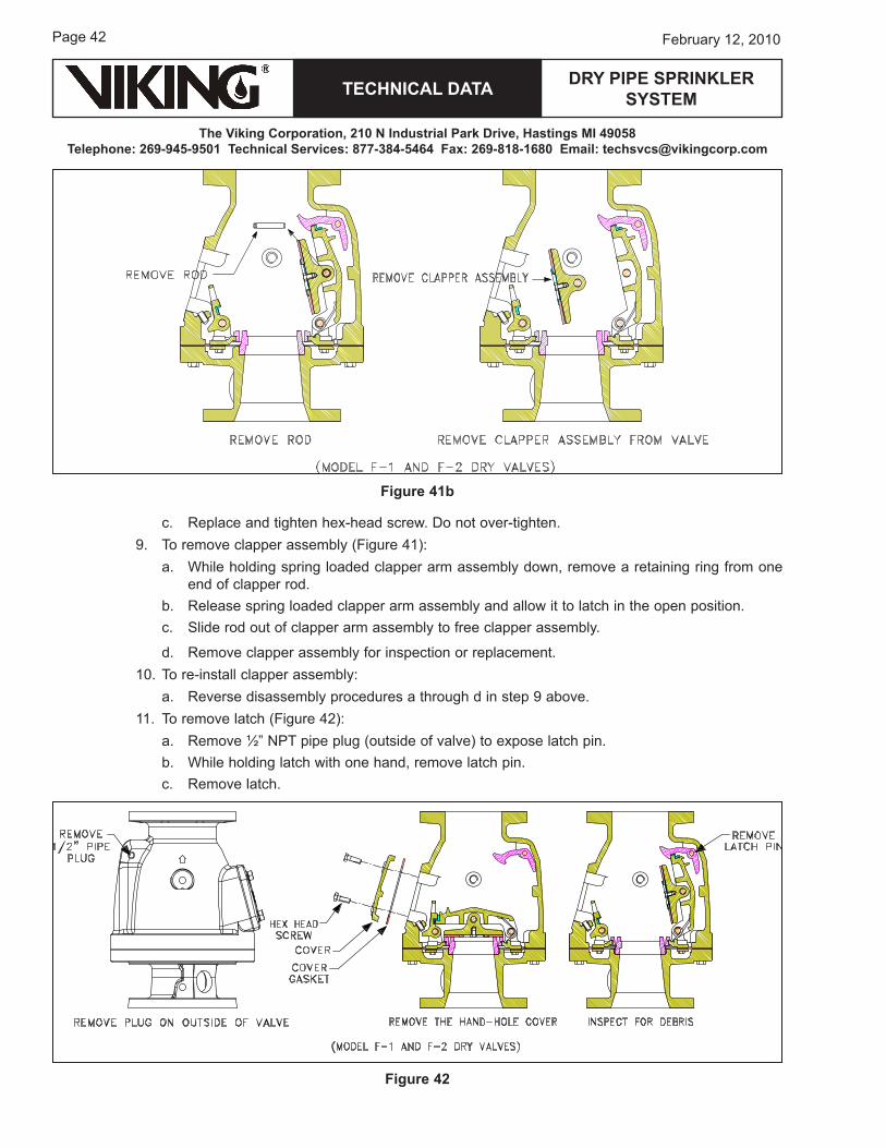
c. replace and tighten hex-head screw. Do not over-tighten. �. To remove clapper assembly (Figure �1):
a. while holding spring loaded clapper arm assembly down, remove a retaining ring from one end of clapper rod.
b. release spring loaded clapper arm assembly and allow it to latch in the open position.c. Slide rod out of clapper arm assembly to free clapper assembly.
d. remove clapper assembly for inspection or replacement.10. To re-install clapper assembly:
a. reverse disassembly procedures a through d in step � above.11. To remove latch (Figure �2):
a. remove ½” NPT pipe plug (outside of valve) to expose latch pin.b. while holding latch with one hand, remove latch pin.c. remove latch.
Figure 42
Figure 41b
TECHNICAL DATA
The Viking Corporation, 210 N Industrial Park Drive, Hastings MI 49058Telephone: 269-945-9501 Technical Services: 877-384-5464 Fax: 269-818-1680 Email: [email protected]
DRY PIPE SPRINkLER SYSTEM
Page ��February 12, 2010
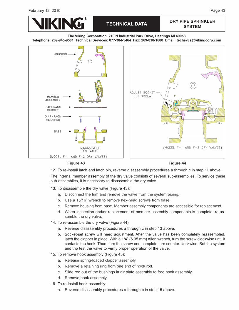
12. To re-install latch and latch pin, reverse disassembly procedures a through c in step 11 above.The internal member assembly of the dry valve consists of several sub-assemblies. To service these sub-assemblies, it is necessary to disassemble the dry valve.
1�. To disassemble the dry valve (Figure ��):a. Disconnect the trim and remove the valve from the system piping.b. use a 1�/16” wrench to remove hex-head screws from base.c. remove housing from base. Member assembly components are accessible for replacement.d. when inspection and/or replacement of member assembly components is complete, re-as-
semble the dry valve.1�. To re-assemble the dry valve (Figure ��):
a. reverse disassembly procedures a through c in step 1� above.b. Socket-set screw will need adjustment. After the valve has been completely reassembled,
latch the clapper in place. with a 1/�” (6.�� mm) Allen wrench, turn the screw clockwise until it contacts the hook. Then, turn the screw one complete turn counter-clockwise. Set the system and trip test the valve to verify proper operation of the valve.
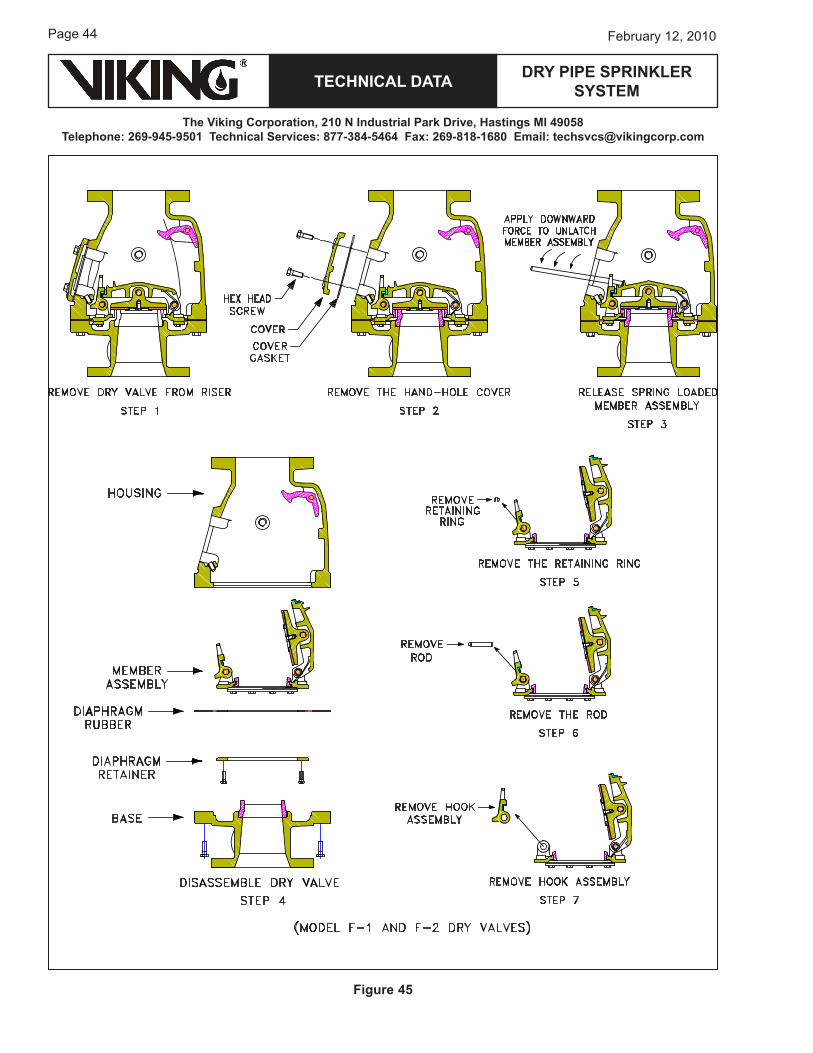
1�. To remove hook assembly (Figure ��):a. release spring-loaded clapper assembly.b. remove a retaining ring from one end of hook rod.c. Slide rod out of the bushings in air plate assembly to free hook assembly.d. remove hook assembly.
16. To re-install hook assembly:a. reverse disassembly procedures a through c in step 1� above.
Figure 44Figure 43
Page ��
TECHNICAL DATA
The Viking Corporation, 210 N Industrial Park Drive, Hastings MI 49058Telephone: 269-945-9501 Technical Services: 877-384-5464 Fax: 269-818-1680 Email: [email protected]
February 12, 2010
DRY PIPE SPRINkLER SYSTEM
Figure 45
TECHNICAL DATA
The Viking Corporation, 210 N Industrial Park Drive, Hastings MI 49058Telephone: 269-945-9501 Technical Services: 877-384-5464 Fax: 269-818-1680 Email: [email protected]
DRY PIPE SPRINkLER SYSTEM
Page ��February 12, 2010
Figure 46a
Page �6
TECHNICAL DATA
The Viking Corporation, 210 N Industrial Park Drive, Hastings MI 49058Telephone: 269-945-9501 Technical Services: 877-384-5464 Fax: 269-818-1680 Email: [email protected]
February 12, 2010
DRY PIPE SPRINkLER SYSTEM
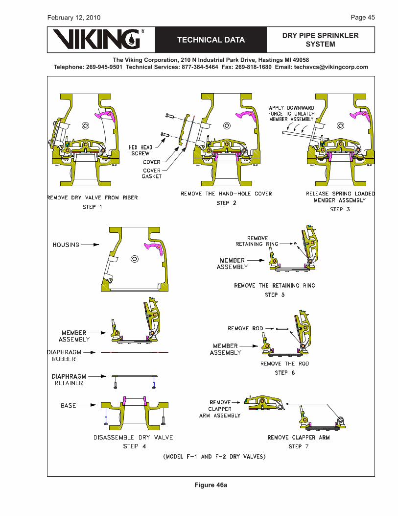
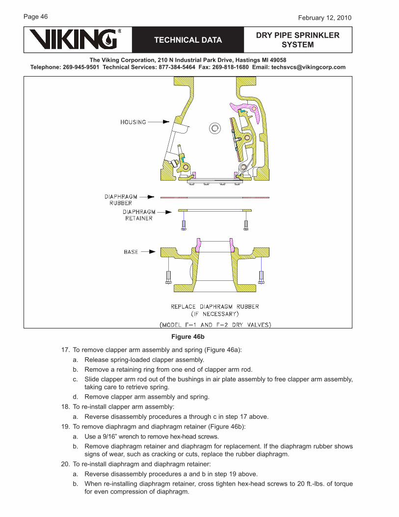
1�. To remove clapper arm assembly and spring (Figure �6a):a. release spring-loaded clapper assembly.b. remove a retaining ring from one end of clapper arm rod.c. Slide clapper arm rod out of the bushings in air plate assembly to free clapper arm assembly,
taking care to retrieve spring.d. remove clapper arm assembly and spring.
18. To re-install clapper arm assembly:a. reverse disassembly procedures a through c in step 1� above.
1�. To remove diaphragm and diaphragm retainer (Figure �6b):a. use a �/16” wrench to remove hex-head screws.b. remove diaphragm retainer and diaphragm for replacement. If the diaphragm rubber shows
signs of wear, such as cracking or cuts, replace the rubber diaphragm.20. To re-install diaphragm and diaphragm retainer:
a. reverse disassembly procedures a and b in step 1� above. b. when re-installing diaphragm retainer, cross tighten hex-head screws to 20 ft.-lbs. of torque
for even compression of diaphragm.
Figure 46b
TECHNICAL DATA
The Viking Corporation, 210 N Industrial Park Drive, Hastings MI 49058Telephone: 269-945-9501 Technical Services: 877-384-5464 Fax: 269-818-1680 Email: [email protected]
DRY PIPE SPRINkLER SYSTEM
Page ��February 12, 2010
c. when assembling base to housing:i. Invert housing on work bench so holes for hex-head screws are facing up.ii. Position complete member sub-assembly with screw holes in diaphragm, aligned with
screw holes in inverted housing. use care to align screw holes so hook assembly properly aligns with set screw.
iii. Position base over inverted housing with member assembly. Align screw holes so ½” (1� mm) NPT trim connection in base aligns with ½” (1� mm) NPT trim connection in housing.
iv. Install hex-head screws finger tight only.v. Cross-tighten all hex-head screws, to evenly compress diaphragm and maintain proper
alignment of member sub-assembly.
B. Model G-2000, G-3000, and G-4000 Dry Valve Maintenance (refer to Figures ��a-��l.)
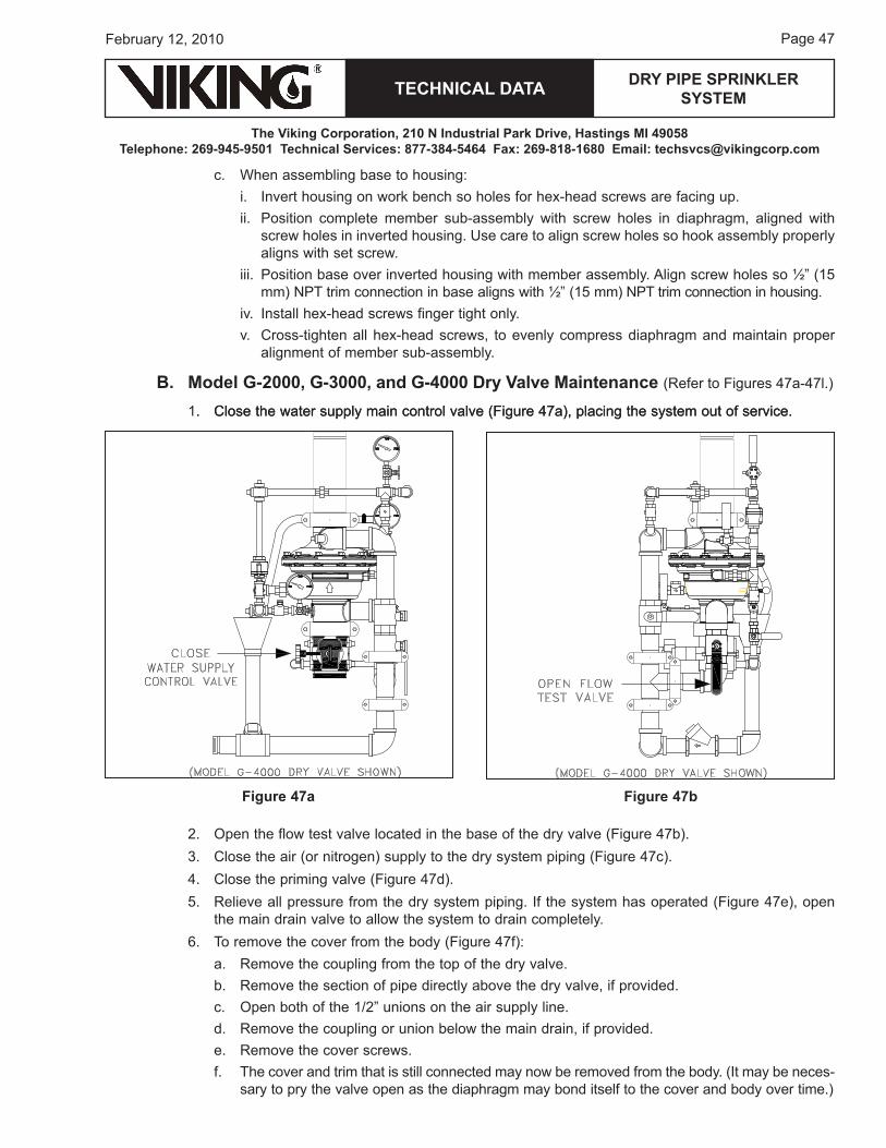
1. Close the water supply main control valve (Figure ��a), placing the system out of service.. Close the water supply main control valve (Figure ��a), placing the system out of service.
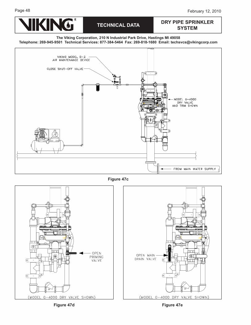
2. open the flow test valve located in the base of the dry valve (Figure ��b).�. Close the air (or nitrogen) supply to the dry system piping (Figure ��c).�. Close the priming valve (Figure ��d).�. relieve all pressure from the dry system piping. If the system has operated (Figure ��e), open
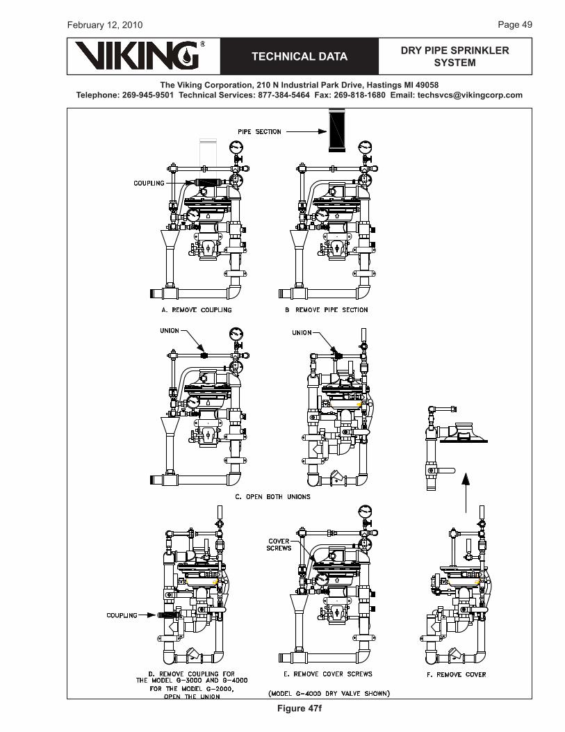
the main drain valve to allow the system to drain completely.6. To remove the cover from the body (Figure ��f):
a. remove the coupling from the top of the dry valve.b. remove the section of pipe directly above the dry valve, if provided.c. open both of the 1/2” unions on the air supply line.d. remove the coupling or union below the main drain, if provided.e. remove the cover screws.f. The cover and trim that is still connected may now be removed from the body. (It may be neces-
sary to pry the valve open as the diaphragm may bond itself to the cover and body over time.)
Figure 47a Figure 47b
Page �8
TECHNICAL DATA
The Viking Corporation, 210 N Industrial Park Drive, Hastings MI 49058Telephone: 269-945-9501 Technical Services: 877-384-5464 Fax: 269-818-1680 Email: [email protected]
February 12, 2010
DRY PIPE SPRINkLER SYSTEM
Figure 47c
Figure 47d Figure 47e
TECHNICAL DATA
The Viking Corporation, 210 N Industrial Park Drive, Hastings MI 49058Telephone: 269-945-9501 Technical Services: 877-384-5464 Fax: 269-818-1680 Email: [email protected]
DRY PIPE SPRINkLER SYSTEM
Page ��February 12, 2010
Figure 47f
Page �0
TECHNICAL DATA
The Viking Corporation, 210 N Industrial Park Drive, Hastings MI 49058Telephone: 269-945-9501 Technical Services: 877-384-5464 Fax: 269-818-1680 Email: [email protected]
February 12, 2010
DRY PIPE SPRINkLER SYSTEM
Figure 47h
Figure 47g
TECHNICAL DATA
The Viking Corporation, 210 N Industrial Park Drive, Hastings MI 49058Telephone: 269-945-9501 Technical Services: 877-384-5464 Fax: 269-818-1680 Email: [email protected]
DRY PIPE SPRINkLER SYSTEM
Page �1February 12, 2010
Figure 47i
Figure 47j
Page �2
TECHNICAL DATA
The Viking Corporation, 210 N Industrial Park Drive, Hastings MI 49058Telephone: 269-945-9501 Technical Services: 877-384-5464 Fax: 269-818-1680 Email: [email protected]
February 12, 2010
DRY PIPE SPRINkLER SYSTEM
Figure 47l
Figure 47k
TECHNICAL DATA
The Viking Corporation, 210 N Industrial Park Drive, Hastings MI 49058Telephone: 269-945-9501 Technical Services: 877-384-5464 Fax: 269-818-1680 Email: [email protected]
DRY PIPE SPRINkLER SYSTEM
Page ��February 12, 2010
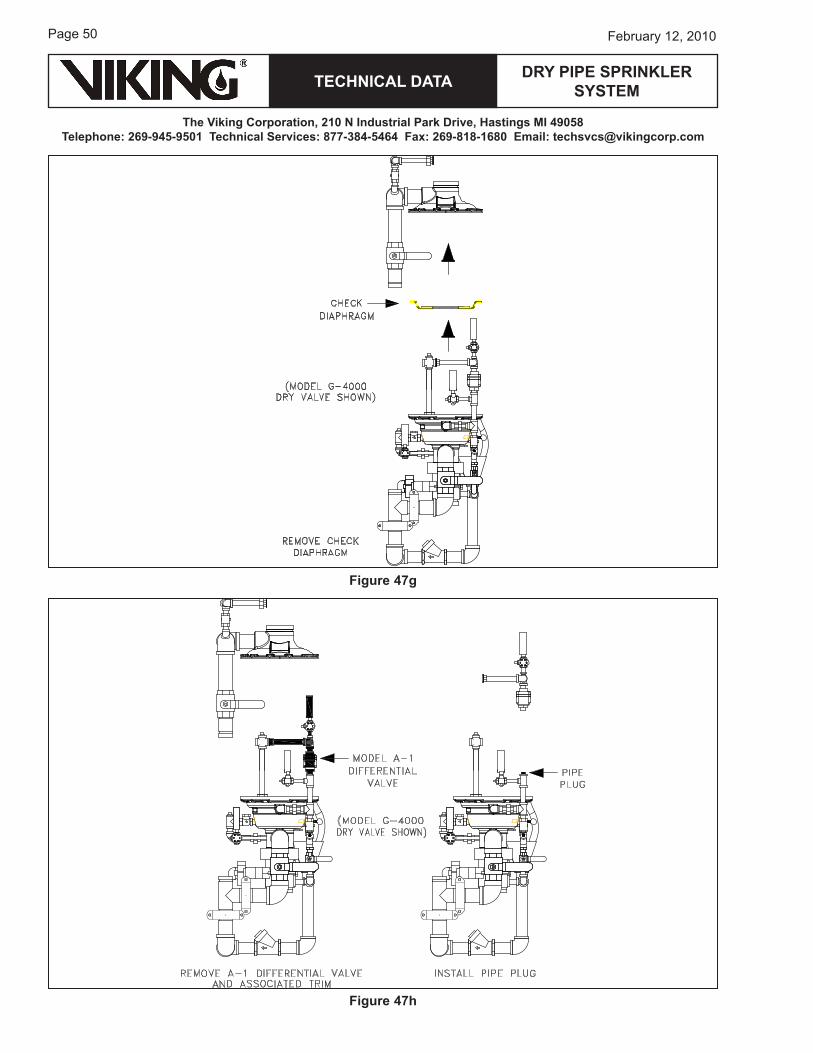
�. To remove / replace the check diaghphragm (Figure ��g):a. The check diaghphragm may be lifted from the valve body.b. If necessary, replace the check diaphragm.
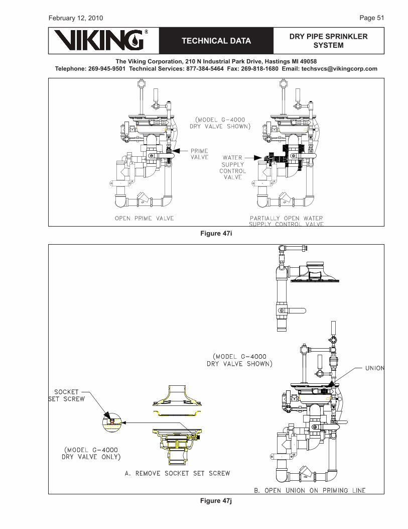
8. To inspect the prime chamber and coupling for leaks (Figure ��h-i):Note: If desired, it is possible to set the G Series Dry Pipe Valve and inspect for leaks with the cover
removed.a. remove the Model A-1 Differential Valve from the prime line and temporarily install a pipe plug. b. Slowly open the prime valve.c. with prime water established, partially open the main water supply control valve.d. Visually inspect the inside of the dry pipe valve for leaks.
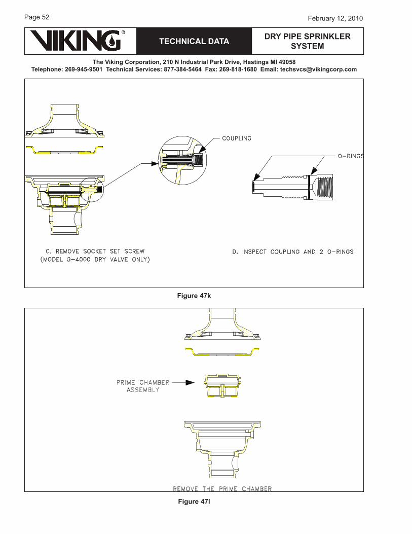
�. To remove / replace the prime coupling (Figure ��j-k):a. For the G-�000 Valve, remove the 1/�” socket set screw.b. open the 1/2” union on the prime line. c. using a wrench on the flats of the coupling, remove the coupling from the valve body.d. Inspect the coupling and 2 o-rings. replace if necessary.
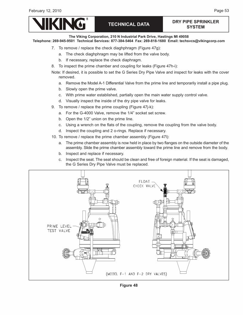
10. To remove / replace the prime chamber assembly (Figure ��l):a. The prime chamber assembly is now held in place by two flanges on the outside diameter of the
assembly. Slide the prime chamber assembly toward the prime line and remove from the body. b. Inspect and replace if necessary. c. Inspect the seat. The seat should be clean and free of foreign material. If the seat is damaged,
the G Series Dry Pipe Valve must be replaced.
Figure 48
Page ��
TECHNICAL DATA
The Viking Corporation, 210 N Industrial Park Drive, Hastings MI 49058Telephone: 269-945-9501 Technical Services: 877-384-5464 Fax: 269-818-1680 Email: [email protected]
February 12, 2010
DRY PIPE SPRINkLER SYSTEM
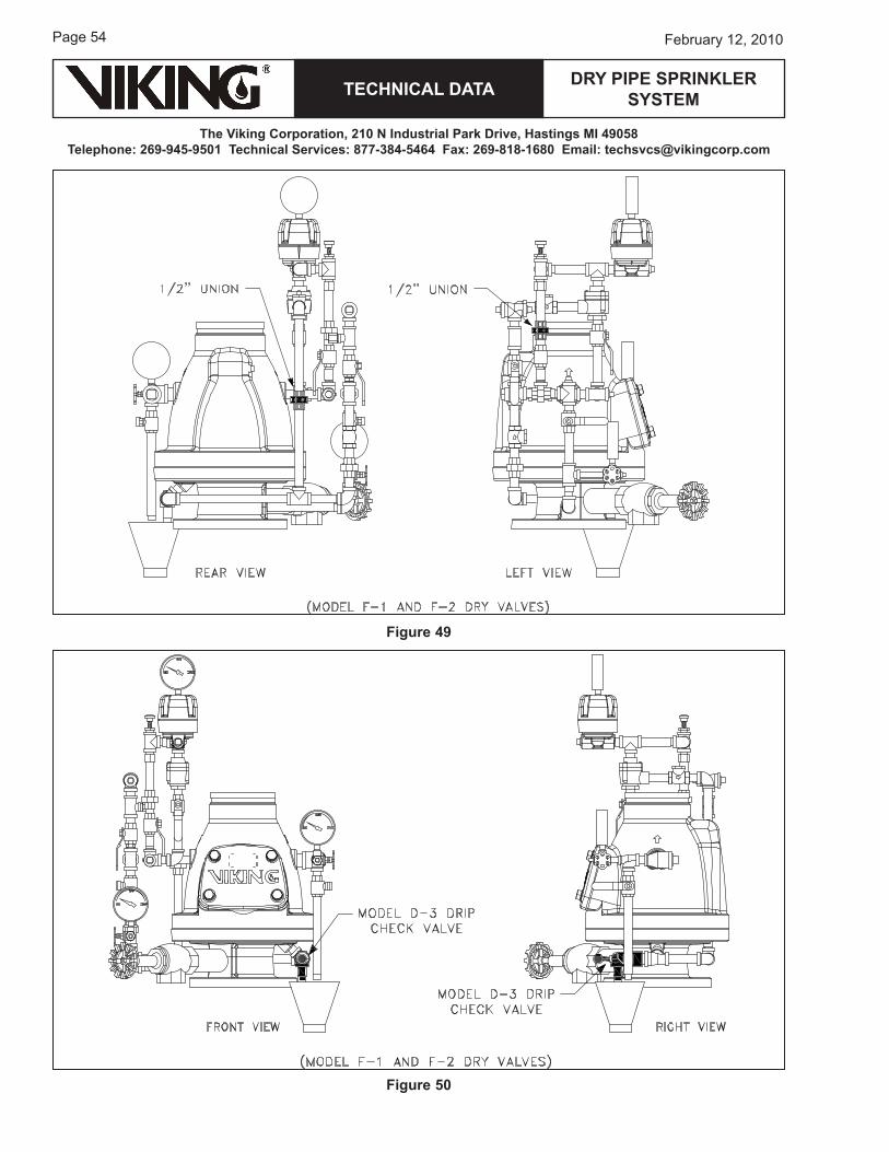
Figure 49
Figure 50
TECHNICAL DATA
The Viking Corporation, 210 N Industrial Park Drive, Hastings MI 49058Telephone: 269-945-9501 Technical Services: 877-384-5464 Fax: 269-818-1680 Email: [email protected]
DRY PIPE SPRINkLER SYSTEM
Page ��February 12, 2010
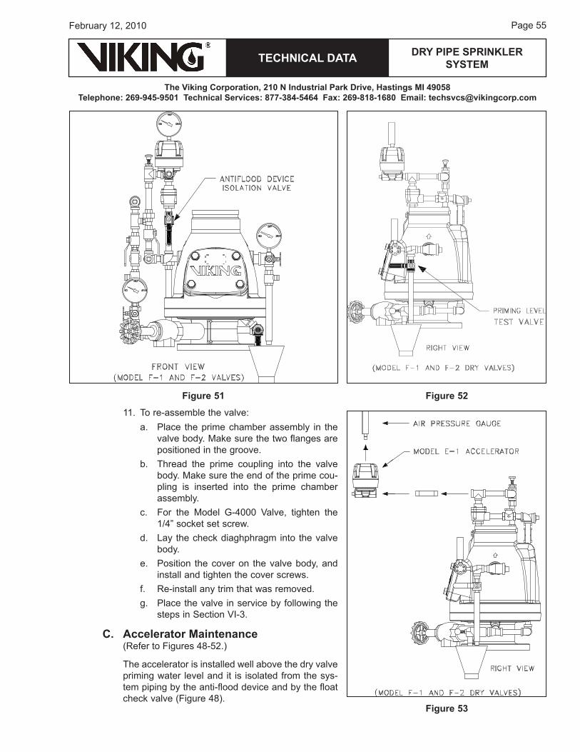
11. To re-assemble the valve:a. Place the prime chamber assembly in the
valve body. Make sure the two flanges are positioned in the groove.
b. Thread the prime coupling into the valve body. Make sure the end of the prime cou-pling is inserted into the prime chamber assembly.
c. For the Model G-�000 Valve, tighten the 1/�” socket set screw.
d. Lay the check diaghphragm into the valve body.
e. Position the cover on the valve body, and install and tighten the cover screws.
f. re-install any trim that was removed.g. Place the valve in service by following the
steps in Section VI-�.
C. Accelerator Maintenance (refer to Figures �8-�2.)
The accelerator is installed well above the dry valve priming water level and it is isolated from the sys-tem piping by the anti-flood device and by the float check valve (Figure �8).
Figure 51 Figure 52
Figure 53
Page �6
TECHNICAL DATA
The Viking Corporation, 210 N Industrial Park Drive, Hastings MI 49058Telephone: 269-945-9501 Technical Services: 877-384-5464 Fax: 269-818-1680 Email: [email protected]
February 12, 2010
DRY PIPE SPRINkLER SYSTEM
The accelerator can easily be removed for service if necessary. unions are included in the antiflood device and accelerator assembly to help facilitate removal of the anti-flood device (Figure ��). before pressurizing the dry pipe system that includes the antiflood device and accelerator assembly, be sure to check the accelerator gauge reads 0. The Viking accelerator is self-setting, but it will only set when no pressure is trapped in the upper chamber. Vent trapped air by loosening the gauge.
open the dry system air supply and establish the necessary system pressure. Verify that the dry valve’s intermediate chamber is free of water (Model F-1 and F-2 Dry Valves). No water should flow from drip check when the plunger is pushed (Figure �0) .
when the pressure on the accelerator pressure gauge equals the system set pressure, be sure that the antiflood isolation is open and secured.
Problems with accelerators are rare with the correct trim arrangement. because the accelerator is isolated from system water by the float check valve and anti-flood device, water can only enter it if one of these devices fails. Due to the simplicity of these devices, such failures are unlikely.
Figure 54
TECHNICAL DATA
The Viking Corporation, 210 N Industrial Park Drive, Hastings MI 49058Telephone: 269-945-9501 Technical Services: 877-384-5464 Fax: 269-818-1680 Email: [email protected]
DRY PIPE SPRINkLER SYSTEM
Page ��February 12, 2010
Figure 55
Figure 56
Page �8
TECHNICAL DATA
The Viking Corporation, 210 N Industrial Park Drive, Hastings MI 49058Telephone: 269-945-9501 Technical Services: 877-384-5464 Fax: 269-818-1680 Email: [email protected]
February 12, 2010
DRY PIPE SPRINkLER SYSTEM
1. To dis-assemble the accelerator:a. Shut off the air supply and close the anti-flood
isolation valve (Figure �1).b. Temporarily open the priming test valve, reliev-
ing pressure in the piping (Figure �2).c. remove the gauge and move the accelerator to
a work bench unless you suspect that the cover diaphragm may be closed (Figure ��). In this case, it is adviseable to service the accelerator in place rather than removing it from the trim. once the accelerator is inverted, any trapped water will plug the cover diaphragm orifice and spring, necessitating replacement.
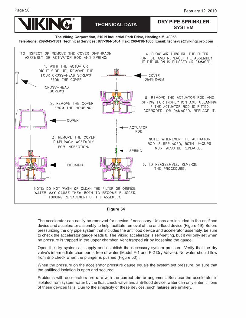
2. To inspect and/or remove cover diaphragm assembly, or actuator rod with spring (Figures ��-��): a. remove the four round-head screws from cover
and lift off cover from housing.b. remove cover diaphragm assembly for inspec-
tion. blow air through filters and orifice. replace the assembly if unit is plugged or damaged. Do not attempt to wash or clean the filters or orifice. water may cause them to become plugged, requiring replacement of the assembly.
c. remove actuator rod with spring for inspection and cleaning. replace the actuator rod if it is pitted, corroded, or damaged.
NOTE: REPLACE BOTH u-CuPS, WHENEVER ACTuATOR ROD IS REPLACED. SEE STEP 3-C.
Figure 57
Figure 58
TECHNICAL DATA
The Viking Corporation, 210 N Industrial Park Drive, Hastings MI 49058Telephone: 269-945-9501 Technical Services: 877-384-5464 Fax: 269-818-1680 Email: [email protected]
DRY PIPE SPRINkLER SYSTEM
Page ��February 12, 2010
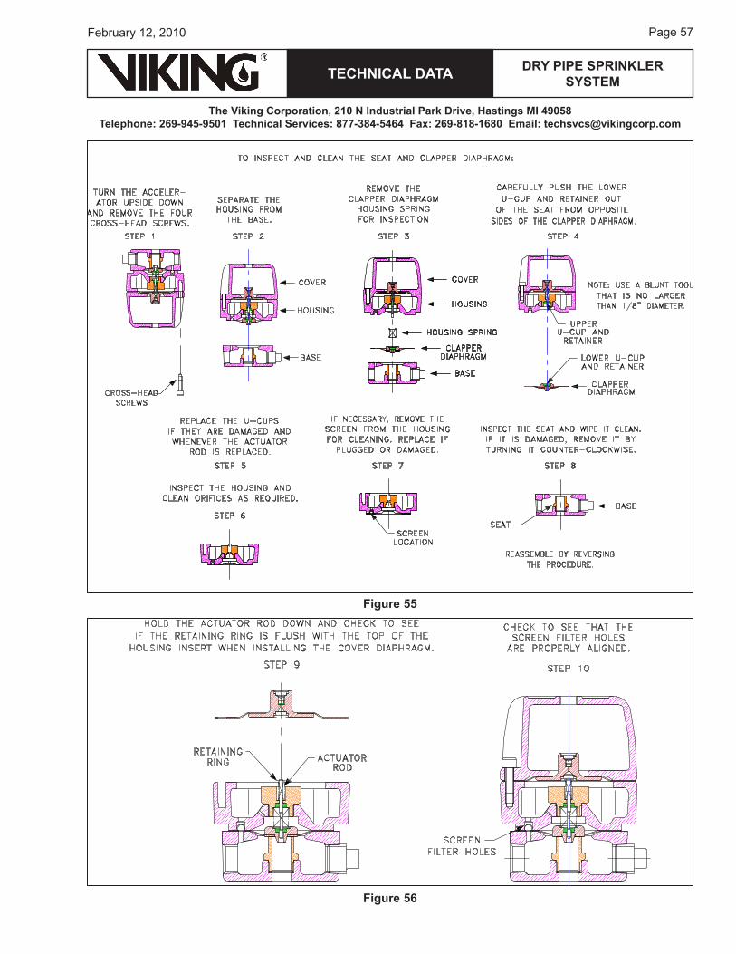
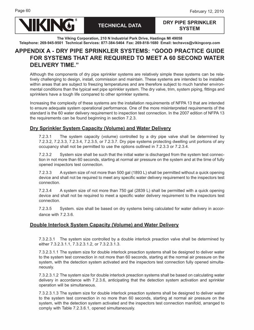
�. To inspect and/or clean seat or inspect and/or remove clapper diaphragm (Figures �6-��):a. remove four round-head screws from base and
separate housing from base.b. remove clapper diaphragm and housing spring for
inspection.c. To remove the lower u-cup retainer, and lower
u-cup for inspection, carefully push them out of their seat from the opposite side of the clapper diaphragm. upper u-cup retainer and u-cup may be removed by pushing them out of their seat from the opposite side of the housing insert.
CAuTION: uSE ONLY A BLuNT TOOL, NOT MORE THAN 1/8” (3.2 mm) DIAMETER, TO PuSH u-CuPS FROM THEIR SEATS. REPLACE u-CuPS IF DAMAGED, AND WHEN-EVER ACTuATOR ROD IS REPLACED.
d. Inspect housing and clean orifices as required. If necessary, remove screen filter from housing for cleaning. replace the screen filter if it is plugged or damaged.
e. Inspect seat. If contamination is detected, wipe clean. If the seat is damaged, remove the damaged seat by turning it counterclockwise, threading it out of base. A �/8” socket wrench is required.
D. Model B-1 Antiflood Device Maintenance (See Figures ��-��.)
The Viking antiflood device does not have the small orifices that other accelerators have, so should be trouble free. To remove the Model b-1 Antiflood Device for inspection and/or maintenance, refer to the trim chart and technical data for the accelerator and dry valve used.
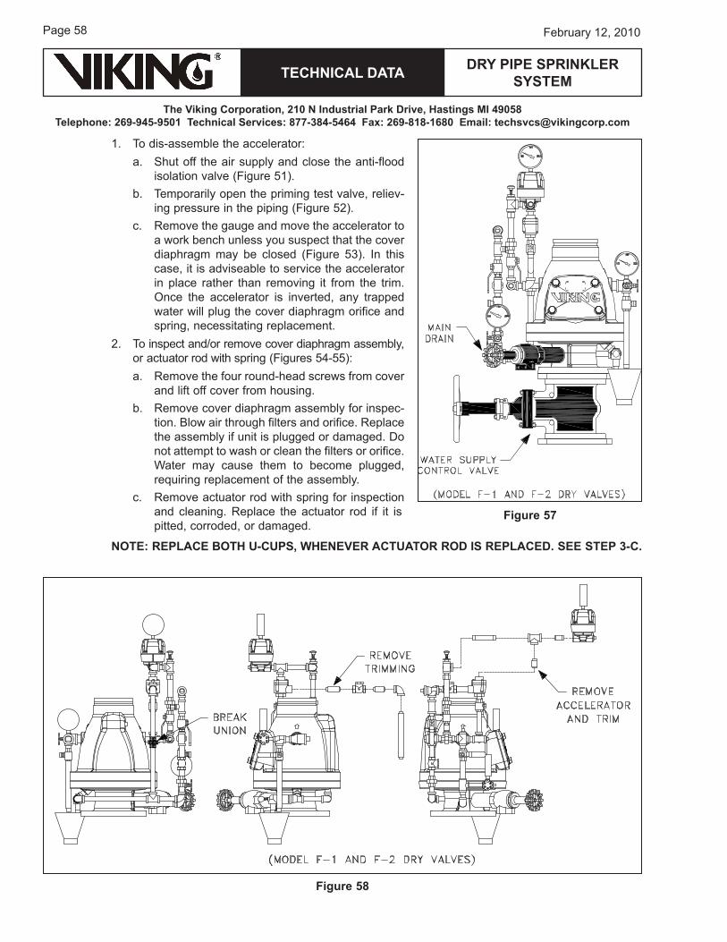
1. Close the water supply main control valve and open the main drain (located on the inlet of the dry valve) (Figure ��), placing the system out of service.
2. Close the ½” antiflood isolation valve (Figure �1).�. Turn off the air supply to the accelerator and
remove the pressure from the piping in which the ac-celerator and antiflood device are installed.
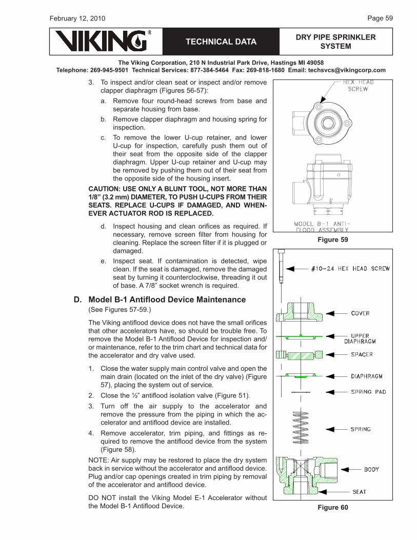
�. remove accelerator, trim piping, and fittings as re-quired to remove the antiflood device from the system (Figure �8).
NoTe: Air supply may be restored to place the dry system back in service without the accelerator and antiflood device. Plug and/or cap openings created in trim piping by removal of the accelerator and antiflood device.
Do NoT install the Viking Model e-1 Accelerator without the Model b-1 Antiflood Device.
Figure 59
Figure 60
Page 60
TECHNICAL DATA
The Viking Corporation, 210 N Industrial Park Drive, Hastings MI 49058Telephone: 269-945-9501 Technical Services: 877-384-5464 Fax: 269-818-1680 Email: [email protected]
February 12, 2010
DRY PIPE SPRINkLER SYSTEM
APPENDIx A - DRY PIPE SPRINkLER SYSTEMS: “GOOD PRACTICE GuIDE FOR SYSTEMS THAT ARE REquIRED TO MEET A 60 SECOND WATER DELIVERY TIME.”Although the components of dry pipe sprinkler systems are relatively simple these systems can be rela-tively challenging to design, install, commission and maintain. These systems are intended to be installed within areas that are subject to freezing temperatures and are therefore subject to much harsher environ-mental conditions than the typical wet pipe sprinkler system. The dry valve, trim, system piping, fittings and sprinklers have a tough life compared to other sprinkler systems.
Increasing the complexity of these systems are the installation requirements of NFPA 1� that are intended to ensure adequate system operational performance. one of the more misinterpreted requirements of the standard is the 60 water delivery requirement to inspection test connection. In the 200� edition of NFPA 1� the requirements can be found beginning in section �.2.�.
Dry Sprinkler System Capacity (Volume) and Water Delivery�.2.�.1 The system capacity (volume) controlled by a dry pipe valve shall be determined by �.2.�.2, �.2.�.�, �.2.�.�, �.2.�.�, or �.2.�.�. Dry pipe systems protecting dwelling unit portions of any occupancy shall not be permitted to use the options outlined in �.2.�.� or �.2.�.�.
�.2.�.2 System size shall be such that the initial water is discharged from the system test connec-tion in not more than 60 seconds, starting at normal air pressure on the system and at the time of fully opened inspectors test connection.
�.2.�.� A system size of not more than �00 gal (18�� L) shall be permitted without a quick opening device and shall not be required to meet any specific water delivery requirement to the inspectors test connection.
�.2.�.� A system size of not more than ��0 gal (28�� L) shall be permitted with a quick opening device and shall not be required to meet a specific water delivery requirement to the inspectors test connection.
�.2.�.� System. size shall be based on dry systems being calculated for water delivery in accor-dance with �.2.�.6.
Double Interlock System Capacity (Volume) and Water Delivery
�.�.2.�.1 The system size controlled by a double interlock preaction valve shall be determined by either �.�.2.�.1.1, �.�.2.�.1.2, or �.�.2.�.1.�.
�.�.2.�.1.1 The system size for double interlock preaction systems shall be designed to deliver water to the system test connection in not more than 60 seconds, starting at the normal air pressure on the system, with the detection system activated and the inspectors test connection fully opened simulta-neously.
�.�.2.�.1.2 The system size for double interlock preaction systems shall be based on calculating water delivery in accordance with �.2.�.6, anticipating that the detection system activation and sprinkler operation will be simultaneous.
�.�.2.�.1.� The system size for double interlock preaction systems shall be designed to deliver water to the system test connection in no more than 60 seconds, starting at normal air pressure on the system, with the detection system activated and the inspectors test connection manifold, arranged to comply with Table �.2.�.6.1, opened simultaneously.
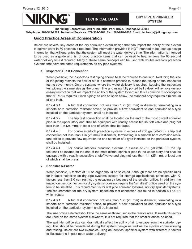
TECHNICAL DATA
The Viking Corporation, 210 N Industrial Park Drive, Hastings MI 49058Telephone: 269-945-9501 Technical Services: 877-384-5464 Fax: 269-818-1680 Email: [email protected]
DRY PIPE SPRINkLER SYSTEM
Page 61February 12, 2010
Good Practice Areas of Consideration
below are several key areas of the dry sprinkler system design that can impact the ability of the system to deliver water in 60 seconds if required. The information provided is NoT intended to be used as design information that will guarantee that the system will meet the water delivery time. The information is intended to be used as a guide and list of good practice items that can be used to help achieve the 60 second water delivery time if required. Many of these same concepts can be used with double interlock preaction systems that have the same requirements as dry pipe systems.
1. Inspector’s Test Connection
when possible, the inspector’s test piping should NoT be reduced to one inch. reducing the size of the piping restricts the flow of air. It is common practice to reduce the piping on the inspectors test to save money. on dry systems where the water delivery is required, keeping the inspectors test piping the same size as the branch line and using fully ported ball valves will remove unnec-essary restriction that will impact the ability of the system to vent air. It is a common misconception that NFPA 1� requires 1 inch piping; as can be seen below, the standard only requires a minimum of one inch.
8.1�.�.�.1 A trip test connection not less than 1 in (2� mm) in diameter, terminating in a smooth bore corrosion resistant orifice, to provide a flow equivalent to one sprinkler of a type installed on the particular system, shall he installed.
8.1�.�.�.2 The trip test connection shall be located on the end of the most distant sprinkler pipe in the upper story and shall be equipped with readily accessible shutoff valve and plug not less than 1 in (2� mm), at least one of which shall be brass.
8.1�.�.�.� For double interlock preaction systems in excess of ��0 gal (28�0 L), a trip test connection not less than 1 in (2� mm) in diameter, terminating in a smooth bore corrosion resis-tant orifice to provide flow equivalent to one sprinkler of a type installed on the particular system, shall be installed.
8.1�.�.�.� Tor double interlock preaction systems in excess of ��0 gal (28�0 L), the trip test shall be located on the end of the most distant sprinkler pipe in the upper story and shall be equipped with a readily accessible shutoff valve and plug not less than 1 in (2� mm), at least one of which shall be brass.
2. Sprinkler k-Factor
when possible, k-factors of 8.0 or larger should be selected. Although there are no specific rules for k-factor selection on dry pipe systems (except for storage applications), sprinklers with k-factors less than 8.0 can restrict the escaping air because of the smaller orifice. In addition, the inspectors test connection for dry systems does not require the “smallest” orifice used on the sys-tem to be installed. This requirement is for wet pipe sprinkler systems, not dry sprinkler systems. The requirements for the dry system inspectors test connection are found in section 8.1�.�.�.1 which reads:
8.1�.�.�.1 A trip test connection not less than 1 in (2� mm) in diameter, terminating in a smooth bore corrosion-resistant orifice, to provide a flow equivalent to one sprinkler of a type installed on the particular system, shall be installed.
The size orifice selected should be the same as those used in the remote area. If smaller k-factors are used on the same system elsewhere, it is not required that the smaller orifice be used.
The sprinkler orifice size can dramatically affect the ability of air to escape from the sprinkler pip-ing. This should be considered during the system design as well as the system commissioning and testing. below are two examples using an identical sprinkler system with different k-factors to illustrate the impact upon water delivery.
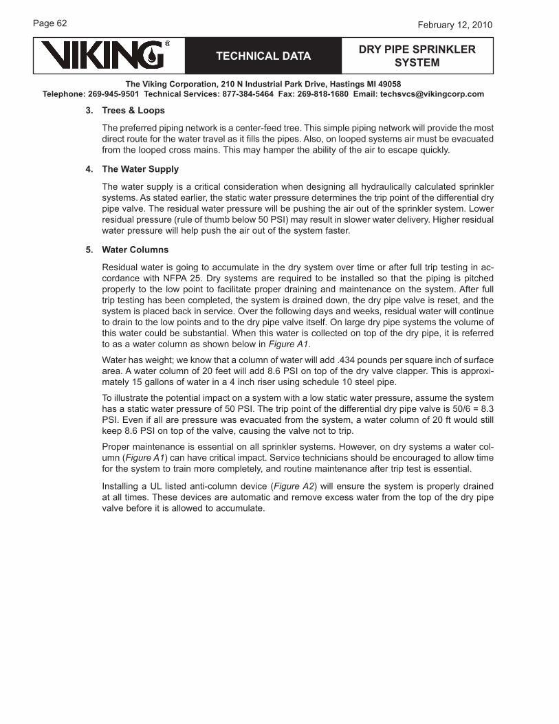
Page 62
TECHNICAL DATA
The Viking Corporation, 210 N Industrial Park Drive, Hastings MI 49058Telephone: 269-945-9501 Technical Services: 877-384-5464 Fax: 269-818-1680 Email: [email protected]
February 12, 2010
DRY PIPE SPRINkLER SYSTEM
3. Trees & Loops
The preferred piping network is a center-feed tree. This simple piping network will provide the most direct route for the water travel as it fills the pipes. Also, on looped systems air must be evacuated from the looped cross mains. This may hamper the ability of the air to escape quickly.
4. The Water Supply
The water supply is a critical consideration when designing all hydraulically calculated sprinkler systems. As stated earlier, the static water pressure determines the trip point of the differential dry pipe valve. The residual water pressure will be pushing the air out of the sprinkler system. Lower residual pressure (rule of thumb below �0 PSI) may result in slower water delivery. higher residual water pressure will help push the air out of the system faster.
5. Water Columns
residual water is going to accumulate in the dry system over time or after full trip testing in ac-cordance with NFPA 2�. Dry systems are required to be installed so that the piping is pitched properly to the low point to facilitate proper draining and maintenance on the system. After full trip testing has been completed, the system is drained down, the dry pipe valve is reset, and the system is placed back in service. over the following days and weeks, residual water will continue to drain to the low points and to the dry pipe valve itself. on large dry pipe systems the volume of this water could be substantial. when this water is collected on top of the dry pipe, it is referred to as a water column as shown below in Figure A1.
water has weight; we know that a column of water will add .��� pounds per square inch of surface area. A water column of 20 feet will add 8.6 PSI on top of the dry valve clapper. This is approxi-mately 1� gallons of water in a � inch riser using schedule 10 steel pipe.
To illustrate the potential impact on a system with a low static water pressure, assume the system has a static water pressure of �0 PSI. The trip point of the differential dry pipe valve is �0/6 = 8.� PSI. even if all are pressure was evacuated from the system, a water column of 20 ft would still keep 8.6 PSI on top of the valve, causing the valve not to trip.
Proper maintenance is essential on all sprinkler systems. however, on dry systems a water col-umn (Figure A1) can have critical impact. Service technicians should be encouraged to allow time for the system to train more completely, and routine maintenance after trip test is essential.
Installing a uL listed anti-column device (Figure A2) will ensure the system is properly drained at all times. These devices are automatic and remove excess water from the top of the dry pipe valve before it is allowed to accumulate.
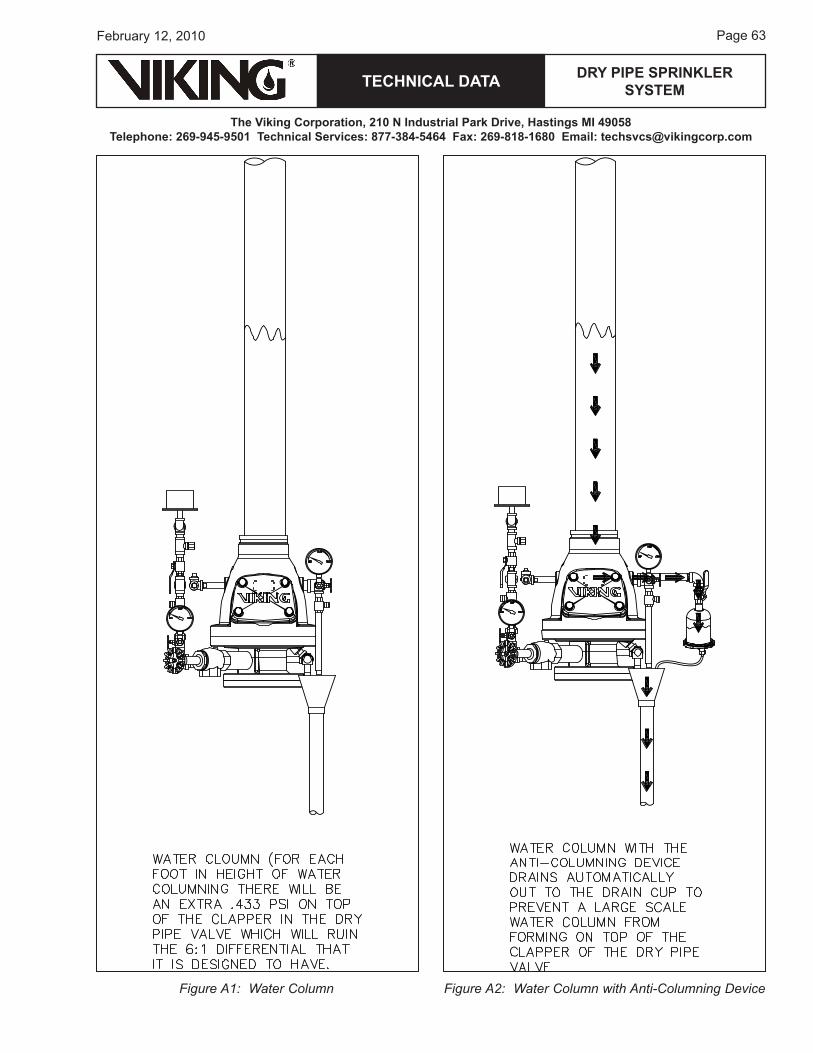
TECHNICAL DATA
The Viking Corporation, 210 N Industrial Park Drive, Hastings MI 49058Telephone: 269-945-9501 Technical Services: 877-384-5464 Fax: 269-818-1680 Email: [email protected]
DRY PIPE SPRINkLER SYSTEM
Page 6�February 12, 2010
Figure A1: Water Column Figure A2: Water Column with Anti-Columning Device
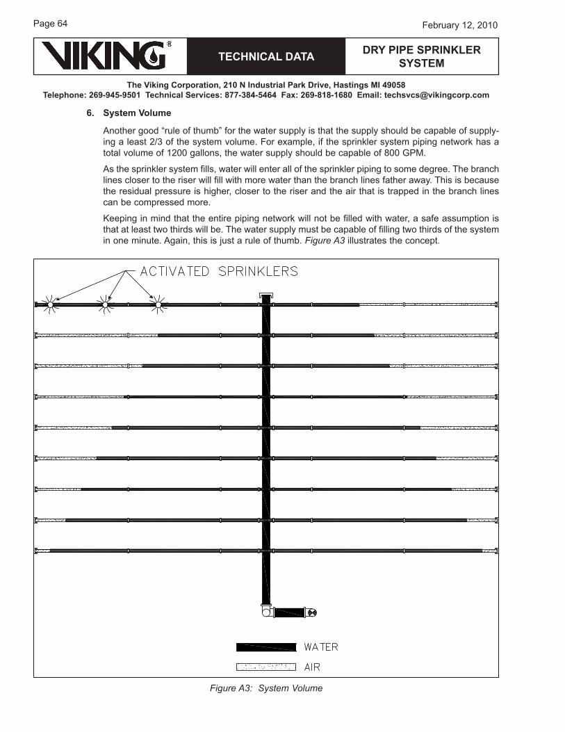
Page 6�
TECHNICAL DATA
The Viking Corporation, 210 N Industrial Park Drive, Hastings MI 49058Telephone: 269-945-9501 Technical Services: 877-384-5464 Fax: 269-818-1680 Email: [email protected]
February 12, 2010
DRY PIPE SPRINkLER SYSTEM
Figure A3: System Volume
6. System Volume
Another good “rule of thumb” for the water supply is that the supply should be capable of supply-ing a least 2/� of the system volume. For example, if the sprinkler system piping network has a total volume of 1200 gallons, the water supply should be capable of 800 GPM.
As the sprinkler system fills, water will enter all of the sprinkler piping to some degree. The branch lines closer to the riser will fill with more water than the branch lines father away. This is because the residual pressure is higher, closer to the riser and the air that is trapped in the branch lines can be compressed more.
keeping in mind that the entire piping network will not be filled with water, a safe assumption is that at least two thirds will be. The water supply must be capable of filling two thirds of the system in one minute. Again, this is just a rule of thumb. Figure A3 illustrates the concept.
TECHNICAL DATA
The Viking Corporation, 210 N Industrial Park Drive, Hastings MI 49058Telephone: 269-945-9501 Technical Services: 877-384-5464 Fax: 269-818-1680 Email: [email protected]
DRY PIPE SPRINkLER SYSTEM
Page 6�February 12, 2010
APPENDIx B - SIzING AIR COMPRESSORS
It is common in the sprinkler industry to size the air compressors to provide �0 psi in �0 minutes. In many cases the formula used to size the compressor is published as .012 x System Volume (gallons), providing the compressor size required in cubic foot (ft�) per minute (CFM).
In many cases �0 PSI is not required for the system.
NFPA 1� 200� Section �.2.6.6.1 states:
“The system air pressure shall be maintained in accordance with the instruction sheet furnished with the dry pipe valve, or 20 PSI (1.� bar) in access of the calculated trip pressure of the dry pipe valve, based on the highest normal pressure of the system supply.”
Sizing the Air Compressor - Manufacture Recommendation Trip Pressure + 15 PSI (Alternative Formula)
The alternative formula for sizing the required Compressor Size in CFM is (V x P) / (�.�8 x 1�.� x T)
where:
V = Volume (determined by using Table � on page 1�)
P = required air pressure [calculated using the highest normal water pressure of the system supply divided by the dry valve differential (6 for Viking dry valves) and then adding 1� psi.]
T = Fill Time (�0 minutes required by NFPA standards)
�.�8 = Gallons per ft�
1�.� = atmospheric pressure
For example, if the system volume (V) is 26� gallons and the required air pressure (P) is �1.� PSI with a required fill time (T) of �0 minutes, (26� x �1.�) / (�.�8 x 1�.� x �0) = 2.���01� CFM. The required com-pressor size is 2.���01� CFM.

Form No. F_010608
THIS PAGEINTENTIONALLY
LEFT BLANk